a study of hydraulic jump in abruptly expanded sloping … horizontal channels. hydraulic jumps in...
TRANSCRIPT
Journal of Civil Engineering (IEB), 36 (2) (2008) 65-77
Experiment on hydraulic jump in sudden expansion in a sloping rectangular channel
M. Abdul Matin1, M. M. Rabiqul Hasan2 and M. Ashraful Islam1
1Department of Water Resources Engineering
Bangladesh University of Engineering and Technology, Dhaka 1000, Bangladesh 2BUET-DUT Project
Bangladesh University of Engineering and Technology, Dhaka 1000, Bangladesh
Received 15 January 2008 _____________________________________________________________________ Abstract Hydraulic jump primarily serves as an energy dissipator to dissipate excess energy of flowing water downstream of hydraulic structures, such as spillways, sluice gates etc. This type of jump is of practical importance in dissipating excess energy downstream of spillways, weirs when tail water depth is inadequate to give a good jump. If this type of jump occurs in a sloping condition the analysis of the phenomenon becomes very complex due to the inclusion of so many parameters related to sudden expansion and channel slope. The sequent depth ratio of a hydraulic jump in an abrupt expansion of a sloping channel is considered in this present study. The results of the present experimental study were used to evaluate a developed prediction equation for computing sequent depth ratio in an expanding channel whose format is similar to the well-known Belanger equation for classical jump with modification of Froude number. This theoretically based equation is easy and simple to apply in design of enlarged stilling basin compared to other approaches. © 2008 Institution of Engineers, Bangladesh. All rights reserved.
Keywords: Experiment, hydraulic jump, expanding sloping channel, sequent depth ratio. 1. Introduction The most important application of the hydraulic jump is in the dissipation of energy below sluiceways, weirs, gates, etc. so that objectionable scour in the downstream channel is prevented. Traditionally, analysis of hydraulic jump is mostly conducted on straight horizontal channels. Hydraulic jumps in such channels are known as classical jump. Overflow weirs with sloping faces and spillways are some examples of situations when the jump occurs on a sloping surface under certain combinations of discharge and tail water conditions. In such basins, there are mainly two problems faced by the field
M.A. Matin et al. / Journal of Civil Engineering (IEB), 36 (2) (2008) 65-77 66
engineers who monitor the performance of the design. One is the determination of sequent depth and the other is the estimation of energy loss (Agarwal 2001). Hydraulic jumps in expanding channels have received considerable attention, although only limited information on successful energy dissipation are available (Nettleton and McCorquodale 1989). Notable efforts have been made by Rajaratnum and Subramanya (1968), Herbrand (1973), Hager (1985), Bremen et. al. (1993,1994). After making several investigations, Herbrand (1973) and Bremen et. al. (1993, 1994), Matin et. al. (1997), Hasan (2001) separately developed equations for sequent depth ratio in channels of abrupt expansion. They studied the characteristics of jump in horizontal channel only. No notable works have been done on hydraulic jump in sloping channel with abrupt expansion. Considering the importance of the topic, the present study has been carried out to evaluate a theoretical model to determine the sequent depth in sloping channel with abrupt expansion. An experimental setup in laboratory has been developed to conduct the study for the analysis of hydraulic jump. Evaluation the necessary parameters of the developed model also done for sequent depth with experimental data. 2. Theoretical expression In the present study, hydraulic jump in an abruptly expanding, rectangular and positive sloping channel will be considered. Particular attention is focused on type of jump of which toe is located at the expansion section. The developed equation for sequent depth ratio is given by:
( )18121 2
1 −+= ED (1)
where D is the sequent depth ratio (h2/h1) of jumps in expanding channel of a sloping floor and E1 is a modified Froude number which incorporates the effect of expansion and slope of the channel. This is expressed as
]sin)[cos1(
)(.
12
11
ddKLD
DBBFE
−−−
−= θγθ
(2)
where,
F1 = Upstream Froude number. B = Expansion ratio, b1/b2
γ = Unit wt of water θ = Channel bottom slope L = Length of the hydraulic jump d2 = Downstream depth d1 = Upstream depth K = Modification factor due to assumption of linear jump profile.
The relationship between E1 and F1 can be rearranged as
θcos)1( 21
212
1 kkFE
−= (3)
M.A. Matin et al. / Journal of Civil Engineering (IEB), 36 (2) (2008) 65-77 67
where k1 is the modifying factor that incorporates the effect of sudden expansion and k2 is the modifying factor that incorporates the effect of channel slope. k1 and k2 can be defined as:
)(1
1 DBBDk−−
= (4)
θγ tan
122 dd
LKk−
= (5)
It is obvious that establishing the relation of sequent depth ratio requires determination of two factors k1 and k2. k1 is a function of expansion ratio and Froude number. k2 is a function of dimensionless jump length, L/(d2-d1) and modifying factor K. These two quantities are again a function of θ. So it is possible to find the factors k1 and k2 from the experimental data and then the sequent depth ratio can be found from the equation (1). 2.1 Calibration of the developed theoretical equation The parameters and of the equation (3) can not be predicted theoretically and hence experimental data are needed to evaluate it. It is necessary to express the parameters and as a function of independent known variables like ,
1k 2k
1k 2k 1F B and θ. For the given values of expansion ratio B and channel slope θ, the sequent depth ratio
have been computed from the present experimental study for different values of inflow Froude number . The observed data are used in equation (4) and (5) to compute
and , respectively. The modified Froude number has been computed from equation (3).
D1F
1k 2k 1E
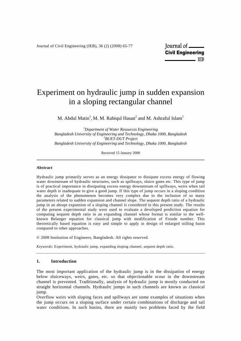
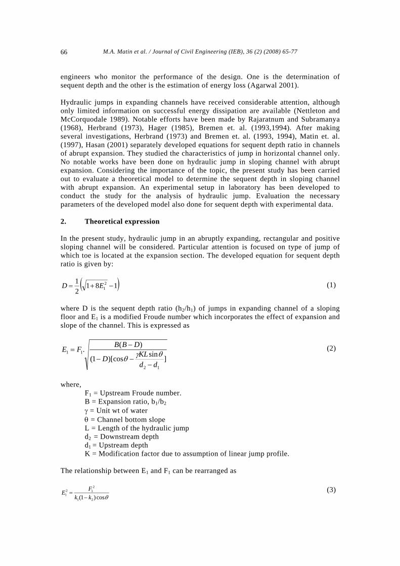
3. Experimental set-up 3.1 General The experiment was conducted in the flume installed at the Hydraulics and River Engineering Laboratory of the Department of Water Resources Engineering, Bangladesh University of Engineering and Technology. The investigations are carried out in a tiltable laboratory flume. The flume has an adjustable tailwater gate located at both upstream and downstream. For the analysis a sluice gate has to be developed to create a hydraulic jump. In addition to the sluice gate, various contraction geometries is inserted in the channel to reduce the width of the supercritical flow upstream of the expansion section. All constriction elements need rounded inlets just upstream from the sluice gate. The downstream width b2 = 3 ft was kept constant and the test was conducted for various expansion ratios. Froude number F1 varied from 2.65 to 10.00. The sketch of the preliminary experimental setup is shown in the following Figure1 and Figure 2.
M.A. Matin et al. / Journal of Civil Engineering (IEB), 36 (2) (2008) 65-77 68
h1
h2
θ
Flow
L
Fig. 1. Definition sketch of the hydr
b1
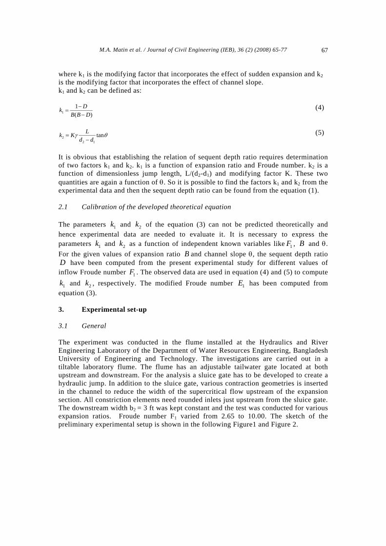
Fig. 2. Expansion geomet 3.2 The flume 21.3m (70 feet) long, 0.76 m (2 feet 6 inches) wiflume was used for wave research (Figure 3). Tilmake it to a sloping channel. It was possible to cchannel (highest possible slope is 1 in 70). To creanecessary to install a sluice gate in the channel. Ain the design, construction and installation of a new
Fig. 3. 21.3 m long laboratory fl
aulic jump in a sloping channel
b2
ry in channel
de and 0.76 m deep glass sided tilting ting facility of the flume was used to reate only mild slopes in this artificial te a hydraulic jump in the channel it is considerable period of time was spent
sluice gate in the flume.
ume for the research
M.A. Matin et al. / Journal of Civil Engineering (IEB), 36 (2) (2008) 65-77 69
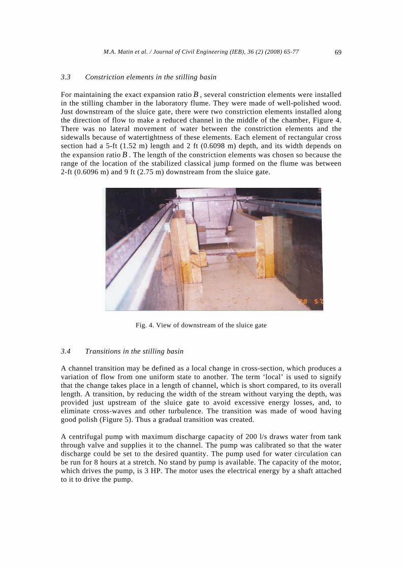
3.3 Constriction elements in the stilling basin For maintaining the exact expansion ratio B , several constriction elements were installed in the stilling chamber in the laboratory flume. They were made of well-polished wood. Just downstream of the sluice gate, there were two constriction elements installed along the direction of flow to make a reduced channel in the middle of the chamber, Figure 4. There was no lateral movement of water between the constriction elements and the sidewalls because of watertightness of these elements. Each element of rectangular cross section had a 5-ft (1.52 m) length and 2 ft (0.6098 m) depth, and its width depends on the expansion ratio B . The length of the constriction elements was chosen so because the range of the location of the stabilized classical jump formed on the flume was between 2-ft (0.6096 m) and 9 ft (2.75 m) downstream from the sluice gate.
Fig. 4. View of downstream of the sluice gate
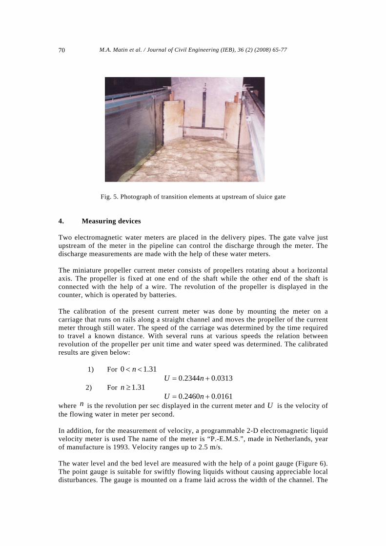
3.4 Transitions in the stilling basin A channel transition may be defined as a local change in cross-section, which produces a variation of flow from one uniform state to another. The term ‘local’ is used to signify that the change takes place in a length of channel, which is short compared, to its overall length. A transition, by reducing the width of the stream without varying the depth, was provided just upstream of the sluice gate to avoid excessive energy losses, and, to eliminate cross-waves and other turbulence. The transition was made of wood having good polish (Figure 5). Thus a gradual transition was created. A centrifugal pump with maximum discharge capacity of 200 l/s draws water from tank through valve and supplies it to the channel. The pump was calibrated so that the water discharge could be set to the desired quantity. The pump used for water circulation can be run for 8 hours at a stretch. No stand by pump is available. The capacity of the motor, which drives the pump, is 3 HP. The motor uses the electrical energy by a shaft attached to it to drive the pump.
M.A. Matin et al. / Journal of Civil Engineering (IEB), 36 (2) (2008) 65-77 70
Fig. 5. Photograph of transition elements at upstream of sluice gate
4. Measuring devices Two electromagnetic water meters are placed in the delivery pipes. The gate valve just upstream of the meter in the pipeline can control the discharge through the meter. The discharge measurements are made with the help of these water meters. The miniature propeller current meter consists of propellers rotating about a horizontal axis. The propeller is fixed at one end of the shaft while the other end of the shaft is connected with the help of a wire. The revolution of the propeller is displayed in the counter, which is operated by batteries. The calibration of the present current meter was done by mounting the meter on a carriage that runs on rails along a straight channel and moves the propeller of the current meter through still water. The speed of the carriage was determined by the time required to travel a known distance. With several runs at various speeds the relation between revolution of the propeller per unit time and water speed was determined. The calibrated results are given below: 1) For 31.10 << n 0313.02344.0 += nU 2) For 31.1≥n 0161.02460.0 += nU where is the revolution per sec displayed in the current meter and U is the velocity of the flowing water in meter per second.
n
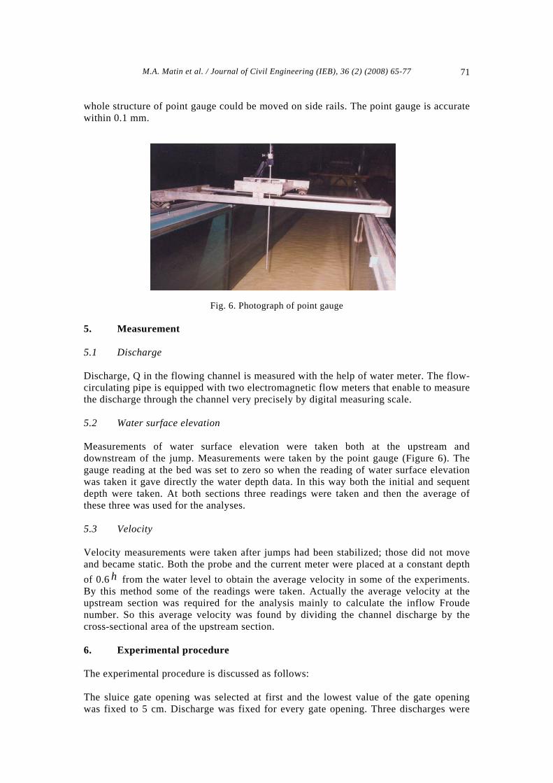
In addition, for the measurement of velocity, a programmable 2-D electromagnetic liquid velocity meter is used The name of the meter is “P.-E.M.S.”, made in Netherlands, year of manufacture is 1993. Velocity ranges up to 2.5 m/s. The water level and the bed level are measured with the help of a point gauge (Figure 6). The point gauge is suitable for swiftly flowing liquids without causing appreciable local disturbances. The gauge is mounted on a frame laid across the width of the channel. The
M.A. Matin et al. / Journal of Civil Engineering (IEB), 36 (2) (2008) 65-77 71
whole structure of point gauge could be moved on side rails. The point gauge is accurate within 0.1 mm.
Fig. 6. Photograph of point gauge 5. Measurement 5.1 Discharge Discharge, Q in the flowing channel is measured with the help of water meter. The flow-circulating pipe is equipped with two electromagnetic flow meters that enable to measure the discharge through the channel very precisely by digital measuring scale. 5.2 Water surface elevation Measurements of water surface elevation were taken both at the upstream and downstream of the jump. Measurements were taken by the point gauge (Figure 6). The gauge reading at the bed was set to zero so when the reading of water surface elevation was taken it gave directly the water depth data. In this way both the initial and sequent depth were taken. At both sections three readings were taken and then the average of these three was used for the analyses. 5.3 Velocity Velocity measurements were taken after jumps had been stabilized; those did not move and became static. Both the probe and the current meter were placed at a constant depth of 0.6 from the water level to obtain the average velocity in some of the experiments. By this method some of the readings were taken. Actually the average velocity at the upstream section was required for the analysis mainly to calculate the inflow Froude number. So this average velocity was found by dividing the channel discharge by the cross-sectional area of the upstream section.
h
6. Experimental procedure The experimental procedure is discussed as follows: The sluice gate opening was selected at first and the lowest value of the gate opening was fixed to 5 cm. Discharge was fixed for every gate opening. Three discharges were
M.A. Matin et al. / Journal of Civil Engineering (IEB), 36 (2) (2008) 65-77 72
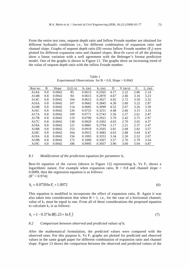
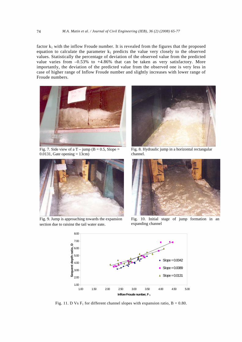
taken to get a range of inflow Froude numbers. By adjusting the tail water gate, location of the hydraulic jump was fixed to the position of abrupt expansion. For the different discharges, the required data for the different jumps with varying Froude numbers were also obtained. The above steps were performed sequentially at the different sluice gate openings in ascending order for different expansion ratios and different channel slopes. In order to carry out the test runs systematically, the experiments are coded. The experimental numbering is chosen in such a way that all the variables (the expansion ratio B , channel slope, the inflow Froude number can be recognized. 1F The first term of the experiment code represents the expansion ratio. In the present study, four different expansion ratios were used. The an expansion ratio B of 0.50 is represented by “A”, an expansion ratio of 0.60 is represented by “B”, an expansion ratio of 0.70 is represented by “C” and an expansion ratio of 0.80 is represented by “D”. The second number in the code represents the channel slope. Test runs were performed for three slopes. The slope 0.0042 is represented by “1”, 0.0089 by “2” and 0.0131 by “3” and “0” represents horizontal channel. The third number in the code represents the gate opening. Data were taken for five gate openings. First reading was taken for gate opening = 5cm. At this time, screw was tightened to 4th hole of the sluice gate. It is represented by “4”, similarly fifth reading was taken for gate opening = 15cm. This is represented by “9” as the screw was tightened to 9th hole. The fourth number in the code represents discharge. For every gate opening, three runs were performed. First run is represented by “A”, second run by “B” and third run is represented by “C”. According to this numbering system, the experiment number B27C means that when the sluice gate size is opening = 11 cm, then a stabilized jump is formed in an expanding channel having an expansion ratio of 0.70 and the channel slope = 0.0089. It also indicates the third reading of this particular gate opening with mentioned expansion ratio and channel slope. 7. Experimental observations For collection of data, four different expansion ratios viz. 0.80, 0.70, 0.60 and 0.50 were chosen. For each expansion ratio, there were three channel slopes – 0.0042, 0.0089 and 0.0131 and five gate openings - 5.0 cm, 9.0 cm, 11.0 cm, 13.0 cm and 15.0 cm where water entered into the expansion section. The data on discharges, sequent depths, and inflow Froude numbers are presented in Table 1. Various features of the hydraulic jump that was analyzed during the course of the study are shown in Figures 7 to 10. 8. Analysis of data The principle objective of this study was to find a mathematical expression for the determination of sequent depth ratio, D from some associated known variables like Inflow Froude number, expansion ratio and channel slope.
M.A. Matin et al. / Journal of Civil Engineering (IEB), 36 (2) (2008) 65-77 73
From the entire test runs, sequent depth ratio and Inflow Froude number are obtained for different hydraulic conditions i.e., for different combination of expansion ratio and channel slope. Graphs of sequent depth ratio (D) versus Inflow Froude number (F1) were plotted for different expansion ratio and channel slopes. Best-fit curve of all the plotting show a linear variation with a well agreement with the Belenger’s format prediction model. One of the graphs is shown in Figure 11. The graphs show an increasing trend of the value of sequent depth ratio with the inflow Froude number.
Table 1 Experimental Observations for B = 0.8, Slope = 0.0042
Run no. B Slope Q (L/s) h1 (m) h2 (m) D V (m/s) F1 Lr (m) A14A 0.8 0.0042 85 0.0615 0.2565 4.17 2.22 2.86 2.14 A14B 0.8 0.0042 94 0.0615 0.2870 4.67 2.46 3.16 3.23 A14C 0.8 0.0042 104 0.0615 0.3027 4.92 2.72 3.50 3.32 A16A 0.8 0.0042 107 0.0662 0.2845 4.30 2.60 3.22 2.87 A16B 0.8 0.0042 114 0.0685 0.3099 4.52 2.67 3.26 3.30 A16C 0.8 0.0042 120 0.0725 0.3251 4.48 2.66 3.15 3.33 A17A 0.8 0.0042 109 0.0771 0.2743 3.56 2.27 2.61 2.47 A17B 0.8 0.0042 119 0.0790 0.2921 3.70 2.42 2.75 2.97 A17C 0.8 0.0042 138 0.0820 0.3302 4.03 2.70 3.02 4.37 A18A 0.8 0.0042 121 0.0881 0.2794 3.17 2.21 2.37 2.47 A18B 0.8 0.0042 153 0.0919 0.3505 3.81 2.68 2.82 3.57 A18C 0.8 0.0042 164 0.0915 0.3683 4.03 2.88 3.04 4.47 A19A 0.8 0.0042 156 0.1003 0.3353 3.34 2.50 2.52 2.67 A19B 0.8 0.0042 172 0.1000 0.3567 3.57 2.76 2.79 3.54 A19C 0.8 0.0042 186 0.0995 0.3937 3.96 3.00 3.04 4.87
8.1 Modification of the prediction equation for parameter k1
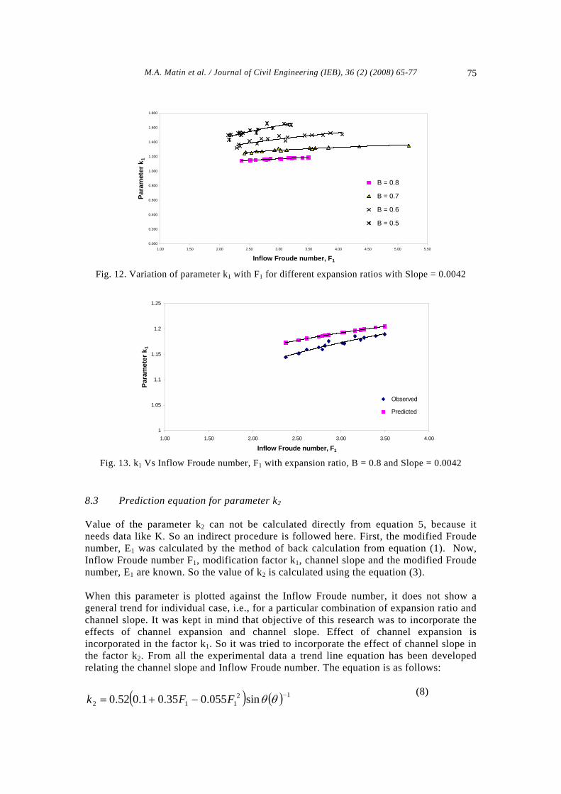
Best-fit equation of the curves (shown in Figure 12) representing k1 Vs F1 shows a logarithmic nature. For example when expansion ratio, B = 0.8 and channel slope = 0.0089, then the regression equation is as follows: (R2 = 0.974):
0972.1ln0759.0 11 += Fk (6) This equation is modified to incorporate the effect of expansion ratio, B. Again it was also taken into consideration that when B = 1, i.e., for the case of a horizontal channel, value of k1 must be equal to one. From all of these considerations the proposed equation to calculate k1 is as follows:
( 11 ln23.1ln37.01 FBk +−= ) (7) 8.2 Comparison between observed and predicted values of k1 After the mathematical formulation, the predicted values were compared with the observed ones. For this purpose k1 Vs F1 graphs are plotted for predicted and observed values in the same graph paper for different combination of expansion ratio and channel slope. Figure 13 shows the comparison between the observed and predicted values of the
M.A. Matin et al. / Journal of Civil Engineering (IEB), 36 (2) (2008) 65-77 74
factor k1 with the inflow Froude number. It is revealed from the figures that the proposed equation to calculate the parameter k1 predicts the value very closely to the observed values. Statistically the percentage of deviation of the observed value from the predicted value varies from –0.53% to +4.86% that can be taken as very satisfactory. More importantly, the deviation of the predicted value from the observed one is very less in case of higher range of Inflow Froude number and slightly increases with lower range of Froude numbers.
Fig. 7. Side view of a T – jump (B = 0.5, Slope = 0.0131, Gate opening = 13cm)
Fig. 8. Hydraulic jump in a horizontal rectangular
channel.
Fig. 9. Jump is approaching towards the expansion section due to raising the tail water gate.
Fig. 10. Initial stage of jump formation in an expanding channel
1.00
2.00
3.00
4.00
5.00
6.00
7.00
8.00
1.00 1.50 2.00 2.50 3.00 3.50 4.00 4.50 5.00
Inflow Froude number, F 1
Sequ
ent d
epth
ratio
, D
Slope = 0.0042
Slope = 0.0089
Slope = 0.0131
Fig. 11. D Vs F1 for different channel slopes with expansion ratio, B = 0.80.
M.A. Matin et al. / Journal of Civil Engineering (IEB), 36 (2) (2008) 65-77 75
0.000
0.200
0.400
0.600
0.800
1.000
1.200
1.400
1.600
1.800
1.00 1.50 2.00 2.50 3.00 3.50 4.00 4.50 5.00 5.50
Inflow Froude number, F1
Para
met
er k
1
B = 0.8
B = 0.7
B = 0.6
B = 0.5
Fig. 12. Variation of parameter k1 with F1 for different expansion ratios with Slope = 0.0042
1
1.05
1.1
1.15
1.2
1.25
1.00 1.50 2.00 2.50 3.00 3.50 4.00
Inflow Froude number, F1
Para
met
er k
1
Observed
Predicted
L
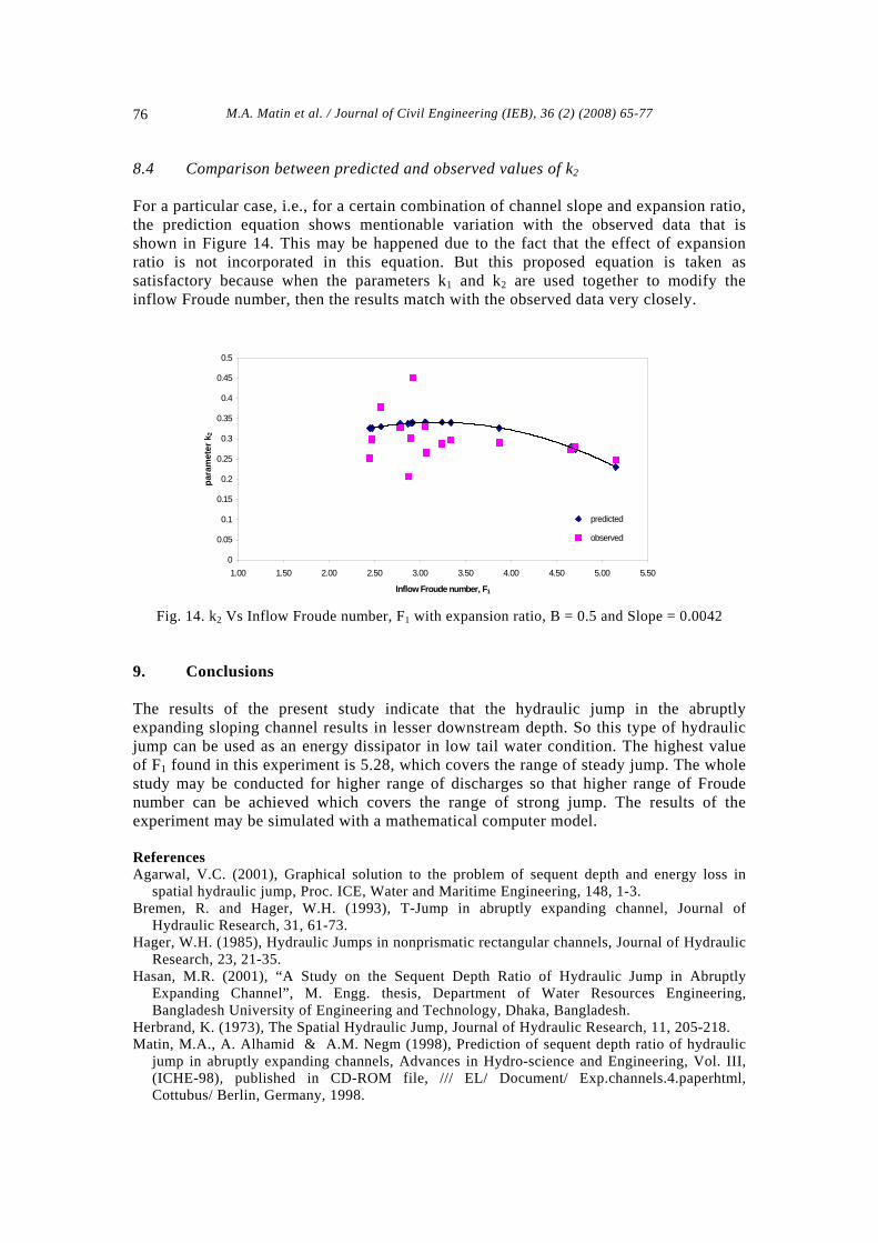
Fig. 13. k1 Vs Inflow Froude number, F1 with expansion ratio, B = 0.8 and Slope = 0.0042 8.3 Prediction equation for parameter k2 Value of the parameter k2 can not be calculated directly from equation 5, because it needs data like K. So an indirect procedure is followed here. First, the modified Froude number, E1 was calculated by the method of back calculation from equation (1). Now, Inflow Froude number F1, modification factor k1, channel slope and the modified Froude number, E1 are known. So the value of k2 is calculated using the equation (3). When this parameter is plotted against the Inflow Froude number, it does not show a general trend for individual case, i.e., for a particular combination of expansion ratio and channel slope. It was kept in mind that objective of this research was to incorporate the effects of channel expansion and channel slope. Effect of channel expansion is incorporated in the factor k1. So it was tried to incorporate the effect of channel slope in the factor k2. From all the experimental data a trend line equation has been developed relating the channel slope and Inflow Froude number. The equation is as follows:
(8) ( ) ( ) 12
112 sin055.035.01.052.0 −−+= θθFFk
M.A. Matin et al. / Journal of Civil Engineering (IEB), 36 (2) (2008) 65-77 76
8.4 Comparison between predicted and observed values of k2 For a particular case, i.e., for a certain combination of channel slope and expansion ratio, the prediction equation shows mentionable variation with the observed data that is shown in Figure 14. This may be happened due to the fact that the effect of expansion ratio is not incorporated in this equation. But this proposed equation is taken as satisfactory because when the parameters k1 and k2 are used together to modify the inflow Froude number, then the results match with the observed data very closely.
0
0.05
0.1
0.15
0.2
0.25
0.3
0.35
0.4
0.45
0.5
1.00 1.50 2.00 2.50 3.00 3.50 4.00 4.50 5.00 5.50
Inflow Froude number, F1
para
met
er k
2
predicted
observed
Fig. 14. k2 Vs Inflow Froude number, F1 with expansion ratio, B = 0.5 and Slope = 0.0042 9. Conclusions The results of the present study indicate that the hydraulic jump in the abruptly expanding sloping channel results in lesser downstream depth. So this type of hydraulic jump can be used as an energy dissipator in low tail water condition. The highest value of F1 found in this experiment is 5.28, which covers the range of steady jump. The whole study may be conducted for higher range of discharges so that higher range of Froude number can be achieved which covers the range of strong jump. The results of the experiment may be simulated with a mathematical computer model.
References Agarwal, V.C. (2001), Graphical solution to the problem of sequent depth and energy loss in
spatial hydraulic jump, Proc. ICE, Water and Maritime Engineering, 148, 1-3. Bremen, R. and Hager, W.H. (1993), T-Jump in abruptly expanding channel, Journal of
Hydraulic Research, 31, 61-73. Hager, W.H. (1985), Hydraulic Jumps in nonprismatic rectangular channels, Journal of Hydraulic
Research, 23, 21-35. Hasan, M.R. (2001), “A Study on the Sequent Depth Ratio of Hydraulic Jump in Abruptly
Expanding Channel”, M. Engg. thesis, Department of Water Resources Engineering, Bangladesh University of Engineering and Technology, Dhaka, Bangladesh.
Herbrand, K. (1973), The Spatial Hydraulic Jump, Journal of Hydraulic Research, 11, 205-218. Matin, M.A., A. Alhamid & A.M. Negm (1998), Prediction of sequent depth ratio of hydraulic
jump in abruptly expanding channels, Advances in Hydro-science and Engineering, Vol. III, (ICHE-98), published in CD-ROM file, /// EL/ Document/ Exp.channels.4.paperhtml, Cottubus/ Berlin, Germany, 1998.

M.A. Matin et al. / Journal of Civil Engineering (IEB), 36 (2) (2008) 65-77 77
Matin, M.A., Negm, A.M., El-Saiad, A.A. and Alhamid, A.A. (1997), Prediction of sequent depth ratio of free hydraulic jump in abruptly enlarged channels, Egyptian Journal for Engineering Sciences & Technology, Vol. 2, No.1, pp. 31-36.
McCorquodale, J.A. (1986), “Hydraulic Jumps and Internal Flows”, Encyclopedia of Fluid Mechanics, Gulf Publishing Company, Houston, Texas, 2, 122-173.
Rajaratnam, N. and Subramanya, K. (1968), “Hydraulic Jumps Below Abrupt Symmetrical Expansions”, Proc. ASCE, Journal of Hydraulics Division, 94, 481-503.