a study of the lines of flow arid the eq,uipotential
TRANSCRIPT

A STUDY OF THE LINES OF FLOW ArID THE EQ,UIPOTENTIAL
LINES IN A PU.TE CmIDUCTOR
By
Willard H. VJhi te t ~\
A Thesis Submitted to the Graduate Committee for
the Degree of
Master of Science
in
Electrical Engineering
Approved:
104A.,~~ Head of Department ~.
~.~ D~neering
Virginia Polytechnic Institute Blacksburg, Virginia
June 1939'

tD 5& v 1C;39u £J5 tfu C.;(

'~fe,440
1
CONTENTS
Page
1. Acknowledgments--------------------------------------------------- 2
2. Introduction------------------------------------------------------ 3
3.
4.
5.
'6 •.
7.
Part I:
Part II:
Part III:
t~pa.rt IV:
Part V:
Lines of Flow Around a Circle---------------------------- 5
Lines of· Flow Around an Oblate Ellipse------------------ll
Lines of Flow Around a Prolate Ellipse-----------------l6
Lines ot Flow Around a Square---------------------------21
The Magnetio Field---------------------------------------23
8. Conclusions-------------------------------------------------------27
9. Bibliography---------------.... --------------------------------------28
1.
2.
3.
4.
5.
6.
7.
8.
9.
10.
Table 1:
Figure 1:
Table 2:
Figure 2:
Table 3:
Figure 3:
Figure 4:
Figure 5:
Figure 6:
Figure 7:
Tables and Illustrations
Calculations for the Cirele~--------------------------- 7
Lines of Flow Around the Circle------------------------10·
Calculations for the Oblate Ellipse--------------------12
Lines of Flaw Around the Oblate Ellipse----------------15
Oalculations for the Prolate Ellipse-------------------17
Lines of: Flow Around the Prolate El1ips&---------------20
One Type of':-;Sehwarz-Christotfel Transformation---------21
Second Type ot SChwarz-Christoffel Transtormation------22
The ~~gnetic Field-------------------------------------25
Conductors in the Magnetic Field-----------------------26

ACRNOWLEOOIvlENTS
The writer takes this opportunity to express his gratitude
to Professors W. A. Murray and B. M. Widener of the Electrical Engi-
neering Department for the many kindnesses shown him both in and out
of the classroom and for their ability to arouse within him a keener
interest in Electrical Engineering.
He desires also to thank Dr. T. W. Hatcher of the Mathematics
Department for presenting to him mathematically many things with which
he had previously been not acquainted.

3
Introduotion
In the field of science Conformal Mapping or Conformal
Representation is a relatively new subject. However. since the
beginning of the twentieth century the application of the mapping
of conjugate or conformal functions to a wide variety of practical
problems has been made. The chief application is to problems of
flow--specifically, to the flow of gases, the flow of liquids,
and the flow of electric currents. Since text books all Complex
Variables and Conjugate Functions deal comprehensively with the
theory of conformal mapping no effort is made herein to outline
the fundamental principles of mapping~.
This treatise will be confined to a discussion of the
flow of electric currents. A thorough study of one particular
type of problem, the flow of an electric current in a plate
conductor around a circular, an elliptic, and a square aperture
will be given with a mathematical analysis of this problem. In
the problem conSidered, a linear source of current is assumed to
be impressed at one end of the plate conductor and a linear sink
is assumed to be at the other end. The current is induced uni
formly from. the source to the Sink.
In the tables of calculations of this paper only the
coordinates of points in the upper right quadrant are shown. In
the graphical representations points in the other three quadrants
were plotted from a knowledge of the symmetry of the problem. and
a study of the symmetry of the function which was used. The symbol
trent used in the tables, represents the base of the natural logarithm.

4
Reference to the Schwarz-Ohristoffel transformation
will be made and an explanation of its failure in one type of
problem will be cited.
So that some comparison might be made between the lines
af flow of an electric current in a plate conductor and the lines
in a magnetic field, a study of a magnetic field is made in
Part v.

5
Part I
TEE LINES OF FLOW AND EQUIPOTENTIAL LINES ARO'U'l\J1) THE CIRCLE
x2/l + y2/1 = 1
In the mapping of the function w = fez) = f(x, jy) there
must be a one-to-one correspondence; that is, for every value of z
in the x, jy plane there is a corresponding value for w in the u, jv
plane and there must be no points of discontinuity.
The continuous function z = w + k \fw2 - 1 is a function
which readily adapts itself to mapping from the w plane to the z plane.
If we consider the constant k ~ 1 then z = w + \/w2 - 1
where both z and Vf are complex. If \"1 :: u + jv then the function z
becomes z = u + jv + \!(u2 - v2 - 1) + 2juv. In computing z for each
value of w there exists the necessity for the evaluation of the square
root of a complex number by either one of two methods. Since the
log z = 1/2(Log t + jQt)~ this method of evaluation introduces unusually
long computations in the solution of a single point only. Hence it is
evident that the radical could be best caloulated by the use of the form
te j9t • In subsequent calculations this is the method used. The
resulting coordinates of each point then are expressed in both polar
and reotangular form.
In the above case k is unity and computations are made for
z corresponding to the straight lines w =, jc parallel to the u axiS,
the lines of flow. Then the resulting lines of flow in the z plane
will be determined for a conductor in which there exists a deleted circle

6
of unit radius. If the lines parallel to the jv axis, W = c, are
mapped in the z plane, these lines will represent the equipotential
lines. It should be observed that in the w plane the eqUipotential
lines are perpendicular to the lines of flow and that in the trans
formation this equality of angles is preserved.
It should be observed further that R ::: m + jn ::: 2"tiT gi ves ~
figure in the R plane similar to that in the w plane but greater in
magnitude. This second translation is necessary for the establishment
of the scale for the proJ)er relationship between the two maps.
The lines of flow in a plate conductor become asymptotic to
the lines of flow arouhd a circular opening. The lines closest to the
opening have the greatest maount of distortion fu~d the lines farther
from the opening flatten out. In a plate v;Those dimensions are large
compared with the size of the opening the lines of flow become practi
cally straight lines at a relatively short distance from the origin.
The necessary calc.ulations for the mapping of the lines of
flovf and the equipotential lines in a plate conductor around a circle
of unit radius are listed in Table 1. Figure 1 shows several of these
lines plotted to scale. The R plane is superimposed on the z plane and
the broken lines represent lines of flow and equipotential lines in the
R plane.

7
Table 1
DATA FOR PLOTTING LINES OF FLOW AROUNJ) THE CIRCLE
x2J1 + y2Jl = 1
Z = W + -\j w2 - 1 = u + jv + \j(u2 - v2 - 1)' + j2uv
1. If v = 0, Z = U + jO + \j(u2 - 1) + jO
v = 0 U = 0 z = 0 + ja.
v = 0 U =, 1 Z = 1.00 + jO
v= 0 u = 2 Z = 3.73 + jO
v= 0 u = 3 Z = 5.83 + jO
v= 0 U= 4 Z = 7.87 + jO
v = 0 u = 5 z = 9.89 + jO
2. If v = :f, Z = U + jl + V(U2 - 1.06) + jO.5u
:t v =.4 U= 0 Z = o + j1.28
v=i u=1 z = 1 + J:t+ 0.29 e j48° 25'
v-1.. - 4; U= 2 Z = 2 + Ji + 1.76 9j100 15'
v-.J.. - 4; u= 3 z = 3+ Ji+ 2.84 e j50 20'
V=; u=4 z=4+ ji + 3.86 e j3° 49'
v=i u= 5 z= 5 + l. j4 + 4.90 9 j20 59'
3. If v = i, Z=U+ j1 2'+ V{U2'- 1.25) + ju
v=t u= 0 z = 0 + j1.61
v-1.. u=l Z = 1 + 3!+ 1.01 ej5~ 01' - 2
V=t- u= 2 z = 2 + Ji + 2.04 e j180 01'
v=! U= 3 Z = 3 + ji + 2.88 e j100 35'
v=i U= 4 Z = 4+ .11+ 3.90 ·7° e J 35'
v=i u=5 Z = 5 + .1!+ 4.92 e j50 57'

u=o
v=i u=l
v=! u = 2
u = 3
v=! u=4
8
z = 0 + j1.99
z = 1 + i! + 1.26 e j55° 14'
z = 2 + J.! + 1.96 e j250 27'
z = 3 + J.! + 2.94 e j150 35'
z = 4- + ~ + 3.93 e j11° 17'
v =: u = 5 z = 5 + J! + 4.96 e j80 52'
5. If v = 1, ~ = u + j1 + V(U2 - 2) + j2u
v=l u = 0 z = 0 + j2.41
v=l U= 1 z = 1 + j1 + 1.50 e j580 17'
v = 1 U= 2 z = 2 + j1 + 2.11 e j310 43'
v = 1 u = 3 z = 3 + j1 + 3.03 e j200 18'
v=l u = 4 z = 4 + j1 + 4.01 e j140 53'
v = 1 n=5 z = 5 + j1 + 5.00 e j110 45'
6. If V = 2t z = u + j2 + V(U2 - 5} + j4u
V= 2 u=o z = 0 + j4.24
v = 2 U= 1 z = 1 + j2 + 2.38 e j670 30'
v = 2 u= 2 z = 2 + j2 + 2.84 e j48° 34'
V= 2 u=3 Z = 3 + j2 + 3.55 e j350 47'
V= 2 u=4- z = 4- + j2 + 4.31 e j270 45'
V= 2 u= 5 z = 5 + j2 + 5.31 e j220 30'

9
7. If v = 3, z = u + j3 + V(u2 - 10} + j6u
V= 3 u = 0 z = 0 + j6.16
V= 3 u = 1 z = 1 + j3 + 3.28 e j730 10'
V= 3 u= 2 z = 2 + j3 + 3.66 e j580 17'
V= 3 u=3 Z = 3 + j3 + 4.24 e j460 35'
v= 3 u=4 z = 4 + j3 + 4.97 ej37° 59'
V= 3 u = 5. Z :: 5 + 13 + 5.79 e j310 43'
8. If v = 4, Z = U + j4 + V(u2 - 17) + j8u
v=4 U== O' z = 0 + j8.12
v=4 u=l z = 1 + j4 + 4.23 e j76° 43'
v=4 U= 2 Z == 2 + j4 + 4.55 e j640 33'
v=4 u=3 Z == 3 + j4 + 5.03 e j54° 13'
v=4 u = 4 Z = 4 + j4 + 5.66 ej450 54'
v=4 u = 5 z = 5 + j4 + 6.39 e j39° 21'
9. If v = 5, Z = U + j5 + \l(u2 - 26) + j10u
V = 5 u= 0 z = 0 + j10.09
v = 5 u = 1 z = 1 + j5 + 5.19 e j79° 06'
V = 5 U= 2 z = 2 + j5 + 5.45 e j680 52'
v == 5 u = 3 z = 3 + j5 + 5.87 e j59° 46'
v=5 u=4 z = 4 + j5 + 6.42 e j5lO 01'
V = 5 U= 5 z = 5 + j5 + 7.07 e j45° 34'
It should be observed that to locate various points on
anyone equipotential line the corresponding values for z in each
of ,the nine sections listed above must be used.

jy
l' I I I I I I
I I 1 I T 1 r I I I I I I I
I I I 1 I
I I I I T - - - - - r- - l"-
I j I I
The z and r planes
r--- - - I - - r--- f- - -Scale 1 n ;: ::3 units
- --,-- - f--
1t .~,= I
~~rt -, r-- L "":-~ , --'I
:x b
- f--I I - - - ~
I I I
I I I
I I I I I I
I I II I
j I I I I I -L I
I I I I
I 1 I I I - r--- I I I I I ' I I I 1 1 1 I _ I 1 1 1 I I I I I ,I
Horizontal Lines: Lines of' Flow
Vertical Lines: Equipotential Lines
Fig. 1

11,
Part II
THE LINES OF FLOW ANDEQ,UIPOTENT!AL LINES AROUND THE ELLIPSE
x2/l + '1'2/4 = 1
In 't'll'orking with the function z = w + k Vw2 - 1 it is
seen that the only change resulting from a change in the oonstant
k is a deorease or inorease, that is a dilation or contraotion,
in the vertical oomponent, the jy component of a number, depending
upon whether the oonstant is less than unity or greater than unity.
In the specific example shown below the value of k was ohosen as
two and the resulting lines of flow were those for a plate conductor
in which there exists a deleted oblate ellipse of the form equated
above.
The data from which these lines of flow and the resulting
equipotential lines are found in Table 2 and the lines, plotted to
scale are ShO\ID in Figure 2. The R plane, R = m + jn = 3w, in this
ease is again superimposed on the z plane.
It should be observed .that the only difference in this
case and the one in Part I is that the lines of flow around this
particular elliptic aperture are "pushed fl farther away from the
origin vertically, that they flatten out and become almost straight
lines as the distance fram the x axis is increased.

12
Table 2
DATA FOR PLOTTmG LINES OF FLOW AROUND THE ELLIPSE
x2/1 + y2/4 == 1
z == w + 2 Vw2 - 1 = u + jv + aV(u2 - v2 - 1) + j2uv
1. If v == 0, z = u + jO + a V(u2 - 1) + jO
V= ° U= 0 Z == 0.00 + j2
v == 0 U= 1 z = 1.00 + jO
v=O u= 2 z = 5:;46 + jO
v=O u=3 Z = 8.66 + jO
v= 0 11=4 z = 11.75 + jO
v=O U= 5 z = 14.79 + jO
2. If v = it z=u+ 3!-'+ 2 V(n2 - 1.06) + jO.5u
v=! u = 0 z = 0 + j2.31
v=i u = 1 z = 1 + .1i- + 0.58 e j480 25 t
v=i u= 2 Z = 2+ ji + 3.52 a j100 15 t
v=i- u=3 z = 3 + It + 5.68 ej50
20t
v=t 11 = 4 z = 4 + it+ 7.72 e j30 49'
v=* u=5 z = 5 +.,.1t + 9.80 e j20 59 t
3 •. If v = i, Z = 11 + jJ-+ 2 V(u2 - 1.25) + ju
v=l 11 = 0 z = 0 + j2.72
v=i 11 == 1 z = 1 + Ji+ 2.02 e j52@ 01'
v=i u= 2 z == 2 + 3i + 4.08 ej180.01 t
v=t u == 3 Z = 3 + ~ + 5.76 &j100
35'
v=t u=4 z = 4 + *+ 7.80 e j7° 35t
v=t 11 == 5 Z == 5 + 3l-+ 9.84 e j50 57'
15
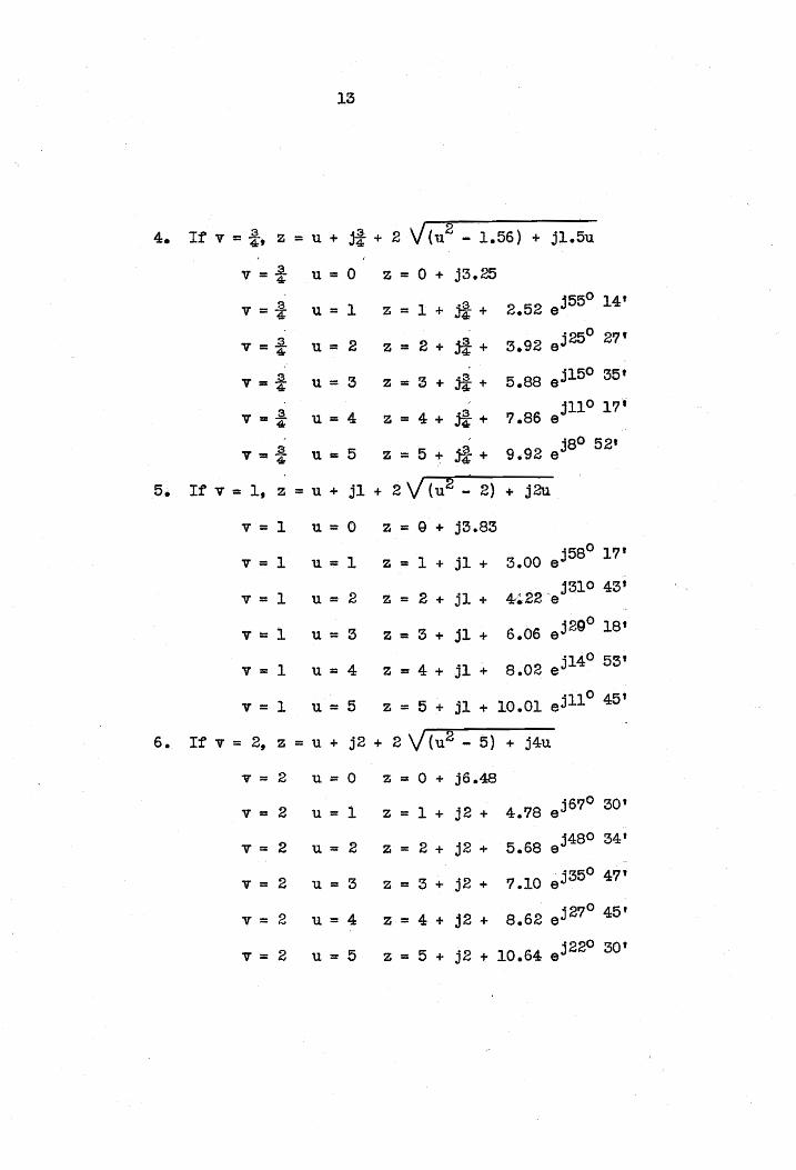
4. If v = !, z = u + 3! + 2 V (u 2
- 1.56) + j1.5u
v=i u=o z = 0 + j3.25
v=! u = 1 z = 1 + j£-+ 2.52 e j550 14t
v=i u= 2 z = 2 + J!+ 3.92 e j250 27'
V=! u=5 z = 3 + j£+ 5.88 e j150 55'
v=! u=4 z=4+ 3!-+ 7.86 e j11° 17'
v=! u=B z = 5 + 3£+ 9.92 e j8() 52'
5. If v = 1, z = u + j1 + 2 V (u2 ~ 2) + j2u
v = 1 u=o z = 9 + j3.83
v=l u=l Z = 1 + j1 + 3.00 e j580 17'
v = 1 2 z = 2 + j1 + 4~·22'e 3310 43'
u=
v=l u= 3 z = 3 + j1 + 5.06 e j29° 18'
v = 1 u=4 z = 4 + j1 + 8.02 e j140 53'
v = 1 u=5 z = 5 + j1 + 10.01 e311° 45'
6. It v = 2, z = u + 32 + 2 V (U2 - 5) + j4u
V= 2 n=O z :: 0 + j6.48
V= 2 U= 1 z = 1 + j2 + 4.78 ej670 30'
V= 2 u= 2 z = 2 + j2 + 5.68 e j480 34t
V= 2 u = 3 z = 3 + 32 + 7.10 e j350 47'
V= 2 11=4 z = 4 + j2 + 8.62 e327° 45 t
V= 2 u=5 z = 5 + 32 + 10.64 e j22° 30'
14
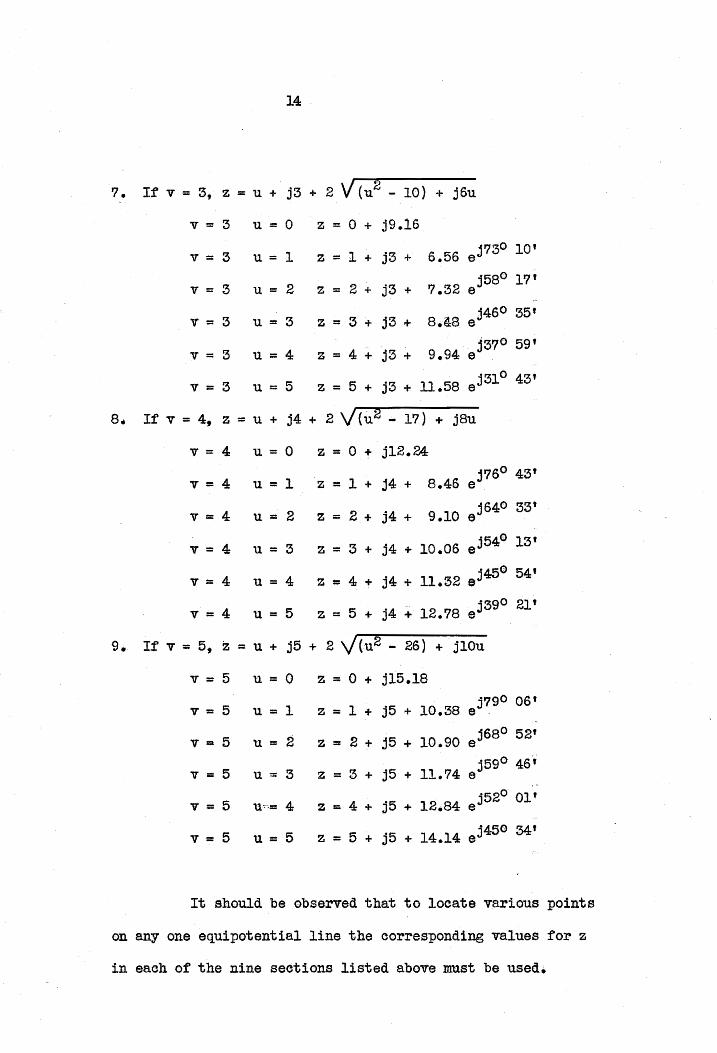
7. If v == 3, Z = U + j3 + 2 V (U2 - 10) + j6u
v== 3 u:: 0 Z == 0 + j9.10
V== 3 U == 1 Z == 1 + j3 + 6.56 e j730 10'
V== 3 u == 2 z :: 2 + j3 + 7.32 e j580 17'
v:: 3 u==3 Z == 3 + j3 + 8.lS e j460 35'
v :: 3 u=4 z :: 4 + j3 + 9.94 e 3370 59'
v == 3 u = 5 z == 5 + j3 + 11.58 e j310 43'
8. If v :: 4, z :: U + j4 + 2 V{u2 ... 17) + j8u
v= 4 u==o Z :: 0 + j12.24
v=4 u=l z = 1 + j4 + 8.46 e j76° 43'
v=4 U== 2 z == 2 .. j4 + 9.10 a j640 33'
v=4 U= 3 z = 3 + j4 + 10.06 e j540 13'
v=4 u==4 z = 4 + j4 + 11.32 ej450 54'
v=4 u=5 z = 5 + j4 + 12.78 ej390 21'
9. If v :: 5, Z = u + j5 + 2 y(u2 - 26) + j10u
v= 5 u== 0 z = 0 + j15.I8
v = 5 u == 1 z = 1 + j5 + 10.38 j790 06'
e '
V= 5 u== 2 z == 2 + j5 + 10.90 e j680 52'
v == 5 U= 3 z = 3 + j5 + 11.74 e j59° 46',
v=5 u',= 4: z = 4 + j5 + 12.84 e j520 01'
v=5 u= 5 Z = 5 + j5 + 14.14 e j450 34'
It should be observed that to locate various points
on anyone equipotential line the corresponding values for z
in each of the nine sections listed above must be used.

--- ~. ---- --t..----T ;
--==Kl11~ ~~0:: ----to- I - ---
- '"-- ---1-'-
I I I , I II
Horizontal Lines: Lines of Flow Vertical Lines: Equipotential Lines
Fig. 2
'mhe
So
z and r planes
ale l~ =2 units
x l-' 01

16:
.PartII!
THE LINES OF FLOW AND Eq,UIPOTENTIAL LINES AROUND TEE ELLIPSE
x2/l + y2/t - 1
It was stated in Part II that a change in the constant k
changed the jy component only in the function z = w + k Vw2 -:- 1
and no contraction or expansion was affected along the x axis. If
the constant is arbitrarily chosen to be one-half, the function
z = w + 0.5 Vw2 - 1 will give the lines of flow and the equipoten-
tiel lines around the prolate ellipse of the form shown above. The
calculations were carried out in the same illaDller as that outlined
in Part I. The effect of the use of the constant k less than unity
is to:mdraw the lines of flow in closer to the origin vertically.
The R plane, R = m + jn = l.5w, in this case is again superimposed ",
on the z plane so that the amount of distortion due to the elliptic
aperture may be clearly seen.
Table 3 lists the data from which the lines of flow and the
eqUipotential lines were plotted to scale and Figure 3 gives a
graphical representation of these lines. In a plate conductor with
a deleted prolate ellipse the lines of flow of an electric current
are not d~~torted to the same degree as in the case of the circle
and these lines of flow flatten out and become almost straight lines
at' an evan shorter distance from the origin.

17
Table 3
DATA FOR PLOTTD\JG LINES OF now AROUND TEE ELLIPSE
~2/1 + y 2/i = 1
_z = W + O.5Y W2 - 1 = u + jv + 0.5 V (u2 - v2 - 1) + j2uv
1. It v == 0, Z = U + jO + 0.5 V ( u 2 - 1) + jO
v = 0 u = 0 z = 0 + jO.5
v = 0 u = 1 z = 1.00 + jO
v = 0 u = 2 z = 2.87 + jO
v = ° u = 3 z = 4.41 + jO
v = 0 u = 4 z = 5.94 + jO
v = 0 u = 5 z = 7.45 • jO
2. If' v = -it Z = U + * + 0.5 Y (u2 - 1.06) + jO.5u
v = t u = 0 z =0 + jO.97
v=j- u=l
vet u=2
vel u=3
va! u=4
z = 1 +
z = 2 +
z=3+
z = 4 +
jt + 0.15 e j48° 25'
.~ 0 88 j100 15 t
~. + • e
~ + 1.42 e j59 20' j30 49 t
~ + 1.93 e j20 59'
v = i u == 5 z = 5 + ji + 2.45 e
3. If v = i, z = U + jl- + 0'.5 V ( u 2 - 1.25) + ju
v=t u=o z = 0 + j1.05
V=i- u = 1 z = 1 + Ji + 0.51 e j52° 01'
vet u= 2 z = :3 + ;Ji+ 1.02 e j180 aI'
vet u=3 z=3+ jj + 1.44 e j100 35t
v=! u=4 z = 4; + -1 195 j'10 35' J2"" • e
vet U = 5 z = 5 + j§-+ 2.46 e j5° 57'

18
4. If v =t;:, Z = U + J!+ 0.5 Y{U2 _ 1.56) + jl.5u
v=! u=o z = 0 + jl.38
v=! u=l z = 1 + .1:i+ 0.63 e j550 14'
v=t 2 2 + 11+ 0.98 ej250 27'
U= z =
v=..§. u=3 3 + 3!+ 1.47 j15° 35'
4: Z = e
v-A - 4- u=4 z = 4 + J!+ 1.97 e j110 17'
. V = A u=5 z = 5 ~+ 2.48 ej80 52'
4- +
5. It v = 1, Z = U + j1 + 0.5 V{U2 - 2): + j2u
v = 1 u = 0 Z = 0 + jl.71
v=l u=l z = 1 + jl + 0.75 e j58° 17'
v=1 U= 2 z = 2 + jl + 1.06 e j31° 43'
v=l U= 3 z = 3 + j1 + 1.52 e j200 18'
v = 1 u=4 Z = 4 + jl + 2.01 e j140 53'
v=1 u = 5 z = 5 + jl + 2.50 e jl1° 45'
6. It v = 2, Z = U + j2 + 0.5 V{U2 - 5) + j4u
V= 2 u = 0 Z = 0 + j3.12
V= 2 u=l Z = 1 + j2 + 1.19 e j67° 30'
v= 2 U = 2 z = 2 + j2 + 1.42 e j480 34'
V= 2 u = 3 Z = 3 + j2 + 1.78 e j350 47'
V= 2 u=4 Z = 4 + j2 + 2.16 e j27° 45'
2 u=5 z = 5 j2 + 2.66 j2~ 30' V= + e

19
7. It v = 3, Z = U + j3 + 0.5 \/(U2 -10) + jou
v=3 u=o z = 0 + j4.58
v=3 u = 1 z = 1 + j3 + 1.64 e j73° 10'
v= 3 U= 2 Z = 2+ j3 + 1.83 e j580 17'
V= 3 u=3 z = 3 + j3 + 2.12 e j46° 35t
V= 3 u=4 z = 4 + j3 + 2.49 e j37° 59'
v = 3 u=5 z :: 5 + j3 + 2.90 e j31° 43'
8. If' v = 4. z=u+ j4 + 0.5 \/(U2 - 17) + jan
v=4 u = 0 z = 0 + j6.06
v=4 u=l z = 1 + j4+ 2.12ej760 43'
v=4 \1= 2 Z = 2 + j4 + 2.28 e j64° 33'
v=4 u= 3 z=3+ j4 + 2.52 e j54° 13'
v=4 u=4 z == 4 + 34 + 2.83 e345° 54'
v=4 u = 5 Z = 5 + j4 + 3.19 e j390 21t
9:. If v = 5. Z=U+ j5 + 0.5 V{u2 - 20) + jlOu
v=5 u=o z == 0 + j7.55
v==5 u=l z = 1 + j5 + 2.60 e j79° 06'
v = 5 u= 2 z = 2 + j5 + 2.73 e j680 52t
v=5 u=3 Z = 3 + j5 + 2.94 e j59° 46'
v=5 u=4 z = 4 + j5 + 3.21 e j52° 01'
v=5 u = 5 Z= 5 + j5 + 3.54 e j45° 34'
It should be observed that to locate various pOints
on· any one equipotential line the corresponding values for z
in each of the nine sections listed above must be used.

jy
The z and r planes -
Scale 1" = 2 units -
~~ -.... .J
~..£, - x ~ 1--1 -
-'. '-
-
"
I I '-
Horizontal Lines: Lines of Flow
Vertical Lines: Equipotential Lines
Fig. 3

21
Part IV
TEE LINES OF FLOW AROUND THE SQ,UARE
The Schwarz- Christoffel transformation of the for.m
where w = u + jv and z = x + jy as derived in most standard text
books on Conjugate Functions gives the transformation of any
polygon of n sides in the z plane to a straight line in the w plane.
The interior angles through which the sides of the polygon must be
rotated to produce a straight line in the w plane are denoted by al ,
a 2, ----, ~ and the distances of the several vertices of the polygon
from the jy axis in the z plane are denoted by Xl' x2' ----, xn. An attempt to find mathematically the lines of flow in a
plate conductor with a deleted unit square in the center of the
conductor (see Fig. 4) was made by the application of the Schwarz-
Christoffel transformation. jv
w plane
o B
D A'
I I u
I I L ____ -'
jy
z plane
D' B' At
Fig. 4
x

22
J.. :t .l.. ~ Equation (A) becomes w = K (z - 2)-2(Z - l)2'(z + 1)2(z + 2)-:2dz
or, W = II: .~ V:~ : ~ dz ----(B). A simple trigonometric subst 1tut ion
shows equation (B) to be an elliptic integral the solution to which
admits of a disoontinuity when z :: jy, that is whenever x = 0 and y = c.
A square of two units, rotated thrQugh forty five degrees,
was studied(see Fig. 5). Equation {AI became w - X \ Jz2 :21 dz.
The solution of this equation likewise runs into an elliptic integral
which is also ~iscontinnous at the origin.
Combinations of several known transformations were attempted,
particularly those for flow around the right angle, but none of these
could be made to satisfy the initial prerequisite e ondit ions which
necessitate that A go into A', B into B'., and C into C'. Experl-
mentally we have found out that the lines of flow do form a smooth,
symmetrical curve but a pure mathematical derivation of lLts~,:equa~iont
by the SChwarz-Christoffel transformation. is not admitted.
jv jy 'W plane z plane
B
C A Of B' A' u x
Fig. 5

Part V
THE :MAGNETIO FIELD
So that there might be some definite basis of comparison
between the lines of flow of an' electric current in a plate conductor
and the lines of a magnetic field two wrought iron p~ates 4" ::x: 5" ::x: ;':'
were wound with 350 turns of No. 20 wire and magnetized by the current
from five Edison cells connected in series. The field between the
two electromagnets was sprinkled with iron filings and a portion of
the field was blocked out first by a right circular cylinder made
frome. nonmagnetic material and the field was photographed.
The field was next disturbed by the insertion of an oblate
and then a. prolate elliptic , cylinder and then by a parallelepiped
with a square cross section. Figures 6a, 6b,6c, and 6d show the
fields in the order named. It is evident from the photographs that
the lines were not disturbed by the insertion c;f a nonmagnetic
obl5J.tacle in the field. Since a magnetic field cannot be insulated,
the magnetic lines do not conform to the theory for the lines of flow
of an electric current in a plate conductor in which certain portions
have been deleted or insulated.
Four plate conductors, 3" x 3", one with a deleted circle,
one with a deleted oblate ellipse, one with a deleted prolate ellipse,
and one with a deleted square were inserted between the magnets. Iron
filings were sprinkled on a zelonite square placed over each conductor
in the order named. When the plates became magnetized the filings
assumed the positions shown in Figures 7a, 7b, 7c, and 7d respectively.
These lines of flow compare favorably with those lines calculated

24
mathematically. The plate conductors were imperfect in consistency
and perfect contact with the magnets could not be accom.plished. In
addition to the, mechanical difficulties which arose, the l'JrOught iron
plate conductors could not be strongly magnetized due to the limitation
in the strength of the magnets and the distance between the poles. The
lines of flow shown in Figures 7a, 7b, 7c, and 7d, do, however, show a
strong tendency to conform to the theoretical lines discussed in the
preceding sections.

-~. --- -
Fig . 6a
Magnetic Field Interrupted by a Circular Cylinder
Fig . 6c
25
Magnetic Field Interrupted by a Prolate Elliptic Cylinder
Fig. 6b
Magnetic Field Interrupted by an Oblate Cylinder{Elliptic)
Fig . 6d
Magmetic Field Interrupted by a Square Parallelepi ped

Fig . 7a
Lines of Flow Around the Circle
Fig . 7c
Lines of Flow Around the Prolate Ellipse
26
Fig . 7b
Lines of Flow Around the Oblate Ellipse
Fig . '1d
Lines of Flow Around the Square

27
Conclusions
1. The function Z= w+ k\fW2 - 1 will represent in the
z plane the lines of flow of an electric current in a plate conductor
around a circle of unit radius if the constant k is unity and around
an ellipse of the form x2/l + y2/k2 = 1 which is oblate if the
constant'k is greater than unity and prolate if the constant k is
less than unity.
2. The lines of flow of an electric current approach
straight lines in the z plane as y increases and the smaller the
vertical axis of the deleted section the smaller will be the dis-~
tortion of the lines of flow.
3. The finding of the lines of flow of an electric current
in a plate conductor around a square section does not admit of a
mathematical solution.
4. The magnetic lines in a field which has been partially
blocked out do not conform to "bending" as do the lines of flow of
an electric current in a plate conductor in which sections of certain
families of geometric figures have been deleted.
5 •. Lines of flow in a plate conductor with certain deleted
geometric sections do conform with the theoretical lines mathematically
calculated and plotted when the conductor is placed in the magnetic
field.

28
Bibliowaphy
Lewent, Leo C 01J70PJIJ.U!J., REPRESENTATION Methuel and Company, Ltd. London, England (1925)
Rothe, R., 011endorff, F., and Pohlausen, K. THEORY OF FUNCTIONS FE APPLIED TO ENGTI\tEERING PROBLEJHS Massachusetts Institute of Technology Press Cambridge, Massachusetts (1933)
Prandtl, Ludwig and Tietjens, Oskar G. APPLIED HYDRO- AND AEROMECIIANIOS :l'vIcGraw Hill Book Company New York City (1934)
Tov\i'11send, E. :r. FUNCTIONS OF THE COMPr:~ ViffiIABLE Henry Holt Book Compe_ny New York City (1915)
Walker, Miles CONJUGATE FlJNCTIOl\[S FOR El'JGniE"8RS Oxford University Press London, England (1933)