a study of wireless telegraphy and wireless telephony
TRANSCRIPT
THE UNIVERSITY
OF ILLINOIS
SiLIBRARY
Els.
3* t£V<
TO

Digitized by the Internet Archive
in 2013
http://archive.org/details/studyofwirelesstOOelea
STUDY OF WIRELESS TELEGRAPHYAND WIRELESS TELEPHONY
BY
ARAM MOVSE8 ELEAZARIAN
THESISFOR THE
DEGREE OF BACHELOR OF SCIENCE
IN
ELECTRICAL ENGINEERING
COLLEGE OF ENGINEERING
UNIVERSITY OF ILLINOIS
1915
UNIVERSITY OF ILLINOIS
«mne i i9i 5
THIS IS TO CERTIFY THAT THE THESIS PREPARED UNDER MY SUPERVISION BY
Aram IJovses jsieazarian
ENTITLED j. Study of tireless Telegraphy
and
Wireless .Telephony
IS APPROVED BY ME AS FULFILLING THIS PART OF THE REQUIREMENTS FOR THE
DEGREE OF Bachelor of Science
in
Ele ctr ic al Engineering
Instructor in Charge
APPROVED:
HEAD OF DEPARTMENT OF.Electrleal Engineering
321505
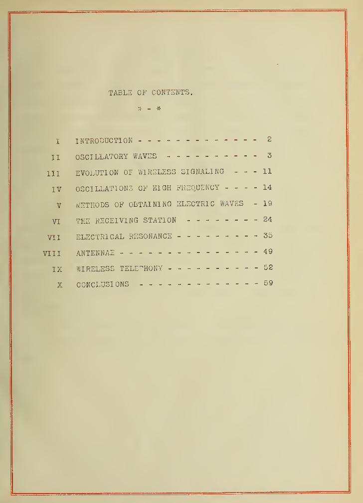
TABLE OF CONTENTS.
I INTRODUCTION ------------- 2
II OSCILLATORY WAVES -- 3
III EVOLUTION OL WIRELESS SIGNALING 11
IV OSCILLATIONS OF HIGH FREQUENCY 14
V METHODS OF OBTAINING ELECTRIC MVES - 19
VI THE RECEIVING STATION -----24
VII ELECTRICAL RESONANCE ---------35
VIII ANTENNAE --- -------49
IX WIRELESS TELEPHONY ----------52X CONCLUSIONS - .---59
2.
I.
INTRODUUTI ON.
The object of the present work was to make a study of the
theory underlying wireless telegraphy and wireless telephony.
' uring the preparation of the thesis the aim has been to briefly
give, in as simple language as possible, a discussion of all of
the principles involved in the science of wireless intercommuni-
cation, together with the devices employed for utilization of
those principles or theorems, due credit being given to the worker
in this field.
To fulfill this object in the short period of time at my
disposal and to enable the reader to get a foothold in this great
and extended science of wireless communication in an easy manner
and in a short period of time, nearly all mathematical treatments
have been avoided. In place of this, a very brief historical
sketch has been prefixed, and the historical aspects of the phen-
omena involved have been tried to make clear without resorting
to mathematics.
It is hoped to have succeeded to make the understanding
of the present work an easy matter to everyone with an elementary
knowledge of electricity.
UIUC
XI.
uSulLLATORY WAVES.
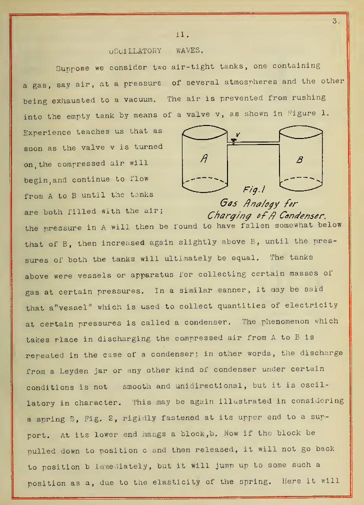
Suppose we consider two air-tight tanks, one containing
a gas, say air, at a pressure of several atmospheres and the other
being exhausted to a vacuum. The air is prevented from rushing
into the empty tank by means of a valve v, as shown in Figure 1.
Experience teaches us that as
soon as the valve v is turned
on, the compressed air will
begin, and continue to flow
from A to B until the tanks
are both filled with the air;
3
Fig. I
Gas Ana/egy for
Chcrrg/ng offt Condenser.
the pressure in A will then be found to have fallen somewhat below
that of B, then increased again slightly above B, until the pres-
sures of both the tanks will ultimately be equal. The tanks
above were vessels or apparatus for collecting certain masses of
gas at certain pressures. In a similar manner, it may be said
that a"vessel" which is used to collect quantities of electricity
at certain pressures is called a condenser. The phenomenon which
takes rlace in discharging the compressed air from A to B is
repeated in the case of a condenser; in other words, the discharge
from a Leyden jar or any other kind of condenser under certain
conditions is not smooth and unidirectional, but it is oscil-
latory in character. This may be again illustrated in considering
a spring S, Fig. 2, rigidly fastened at its upper end to a sup-
port. At its lower end hangs a block, b. Now if the block be
pulled down to position c and then released, it will not go back
to position b immediately, but it will jump up to some such a
position as a, due to the elasticity of the spring. Here it will
4.
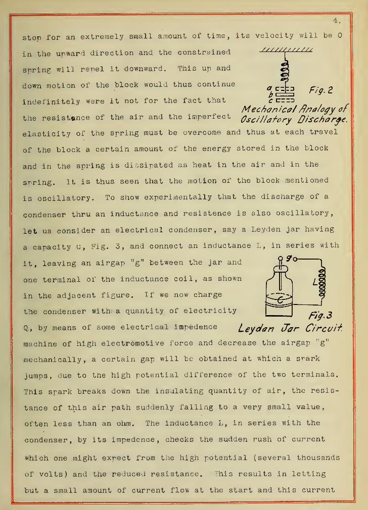
stop for an extremely small amount of time, its velocity will be
in the upward direction and the constrained CL£ZZ^LLL£U
srring will repel it downward. This up and
down motion of the block would thus continue
indefinitely were it not for the fact that c czzzt
Mechanical fl/ia/ogy ofthe resistance of the air and the imperfect Oscillatory Discharge.
elasticity of the spring must be overcome and thus at each travel
of the block a certain amount of the energy stored in the block
and in the spring is dissipated as heat in the air and in the
spring. It is thus seen that the motion of the block mentioned
is oscillatory. To show experimentally that the discharge of a
condenser thru an inductance and resistence is also oscillatory,
let us consider an electrical condenser, say a Leyden jar having
a capacity U, Fig. 3, and connect an inductance L, in series with
it, leaving an airgap "g" between the jar and Jj ^° 1
one terminal of the inductance coil, as shown ^in the adjacent figure. If we now charge
the condenser with a quantity of electricity^
Q, by means of some electrical impedenee Leydan Jar Circuit.
machine of high electromotive force and decrease the airgap ; 'g"
mechanically, a certain gap will be obtained at which a srark
jumps, due to the high potential difference of the two terminals.
This spark breaks down the insulating quantity of air, the resis-
tance of this air path suddenly falling to a very small value,
often less than an ohm. The inductance L, in series with the
condenser, by its irapedence, checks the sudden rush of current
which one might expect from the high potential (several thousands
of volts) and the reduced resistance. This results in letting
but a small amount of current flow at the start and this current
5.
reaches its maximum after a certain short interval. At this
stage, that is, when the current has reached its maximum, the
condenser is nearly discharged, but a large current continues.
This current flows, even though the electromotive force of the
condenser has become zero, since an active electromotive force
is induced in the induction coil by the change in its magnetism
and does not allow the current to come to zero value suddenly.
This process charges the condenser oppositely to its original
charge and when the current in this direction ceases, the back
electromotive force of the condenser starts the current in the
reverse direction. This process then repeats again and again,
until the oscillations reduce to zero, the rapidity of oscilla-
tions depending upon the values of self inductance, capacity
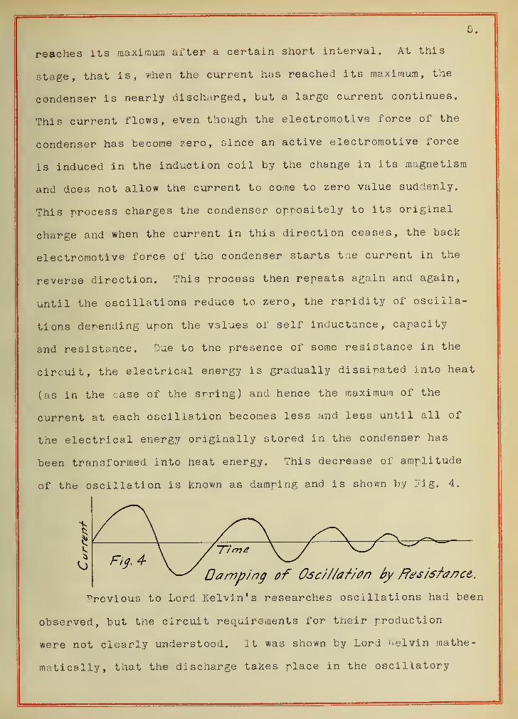
and resistance. Due to tne presence of some resistance in the
circuit, the electrical energy is gradually dissipated into heat
(as in the case of the spring) and hence the maximum of the
current at each oscillation becomes less and less until all of
the electrical energy originally stored in the condenser has
been transformed into heat energy. This decrease of amplitude
of the oscillation is known as damping and is shown by Fig. 4.
Previous to Lord Kelvin's researches oscillations had been
observed, but the circuit requirements for their production
were not clearly understood. it was shown by Lord Kelvin mathe-
matically, that the discharge takes place in the oscillatory
6.
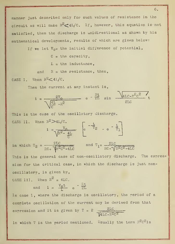
manner just described only for such values of resistance in the
circuit as will make R2<4L/C. If, however, this equation is not
satisfied, then the discharge is unidirectional as shown by his
mathematical developments , results of which are given below:
If we let V = the initial difference of potential,
C = the capacity,
L s the inductance,
and R = the resistance, then,
CASE I. When R2<4L/C.
Then the current at any instant is,
i =2V.
Rt"2~C sin
4LC-R2C2 7
^ -R22LC
This is the case of the oscillatory discharge.
CASE II. When R2>4L/C.
1 =A/r2 - 4LV C
J,T2 - e
t
Tl
in which To =2LC
arid T1=-^gLC^ =
RC+ ~AR2 C 2 -4LC
This is the general case of non-oscillatory discharge. The express
sion for the critical case, in which the discharge is just non-
oscillatory, is given by,
2CASE III. When R = 4LC
.
and i =V t
L
Rt2L
In case I, where the discharge is oscillatory, the period of a
complete oscillation of the current may be derived from that
expression and it is given by T = 22LC
~\/4LC-R2C 2
in which T is the period mentioned. Usually the term R 2 C 2 is
7.
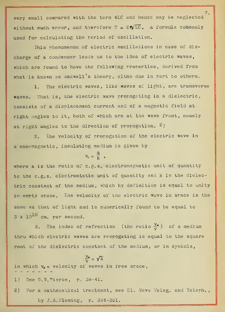
very small compared with the term 4LC and hence may be neglected
without much error, and therefore T = 2r/LC, a formula commonly
used for calculating the period of oscillation.
This phenomenon of electric oscillations in case of dis-
charge of a condenser leads us to the idea of electric waves,
which are found to have the following properties, derived from
what is known as maxwell's theory, altho due in part to others.
1. The electric waves, like waves of light, are transverse
waves. That is, the electric wave prorogating in a dielectric,
consists of a displacement current and of a magnetic field at
right angles to it, both of which are at the wave front, namely
at right angles to the direction of propogation. 2)
2. The velocity of propogation of the electric wave in
a non-magnetic, insulating medium is given by
a
where a is the ratio of c.g.s. electromagnetic unit of quantity
to the c.g.s. electrostatic unit of quantity and k is the dielec-
tric constant of the medium, which by definition is equal to unity
in empty space. The velocity of the electric wave in space is the
same as that of light and is numerically found to be equal to
3 x 10¹⁰
cm. per second.
3. The index of refraction (the ratio —* ) of a medium
thru which electric waves are propogating is equal to the square
root of the dielectric constant of the medium, or in symbols,
/kv r
in which v„ = velocity of waves in free space,
1) See G. W.Pierce, p. 39-41.
2) For a mathematical treatment, see El. Wave Teleg. and Teleph.
,
by J. A. Fleming, p. 344-351.
8.
and v = velocity ox' waves in the dielectric.
4. Good conductors are opaque to electric waves; good
insulators are transparent to electric waves and semiconductors
like wood and stone are serai transparent . Metallic surfaces are
practically perfect reflectors of electric waves. 1
ns a conclusion it must be said that Maxwell's mathematical
researches later proved of great practical value in the under-
standing and rapid development of wireless telegraphy. In order
that the effects of these currents ae appreciable, they must
change frequently in direction, that is, the alternations must
be rapid. The means of producing such high number of alternations
at his disposal were rather limited and the joy of confirming
Maxwell's theory came some twenty years later when iiertz under-
took the proposition and was crowned with success.
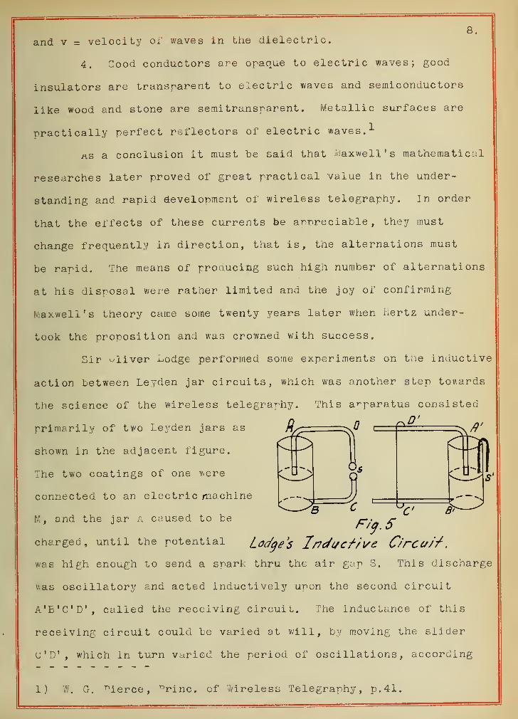
Sir sliver ^odge performed some experiments on the inductive
action between Leyden jar circuits, which was another step towards
the science of the wireless telegraphy. This apparatus consisted
D'primarily of two Leyden jars as
shown in the adjacent figure.
The two coatings of one were
connected to an electric machine
M , and the jar A caused to be
charged, until the potential Lodges 1ffcfl/cfi\/e C/rC(//'f
.
was high enough to send a spark thru the air gap S. This discharge
v.as oscillatory and acted inductively upon the second circuit
A'B'C'D', called the receiving circuit. The inductance of this
receiving circuit could be varied at will, by moving the slider
u'D', which in turn varied the period of oscillations, according
1) Cr. ^ierce, ^rinc. cf tireless Telegraphy, p. 41.
9.
to the relation T=2<j-/LC, in which
T s period of oscillations,
L = inductance,
C = capacity.
It was found by Lodge, that there was a certain position of slider
C'D 1 that gave the maximum effect at the receiving circuit, as
shown by the lively passage of sparks at the gap S'. This meant
that the two circuits had the same reriod of oscillation, namely
that they were in resonance. Lodge, however, was not able to
prove experimentally that the inductive action between two circuits
consisted of electric waves sent out from the discharge circuit
and striking the receiving circuit, as Maxwell's theory shows.
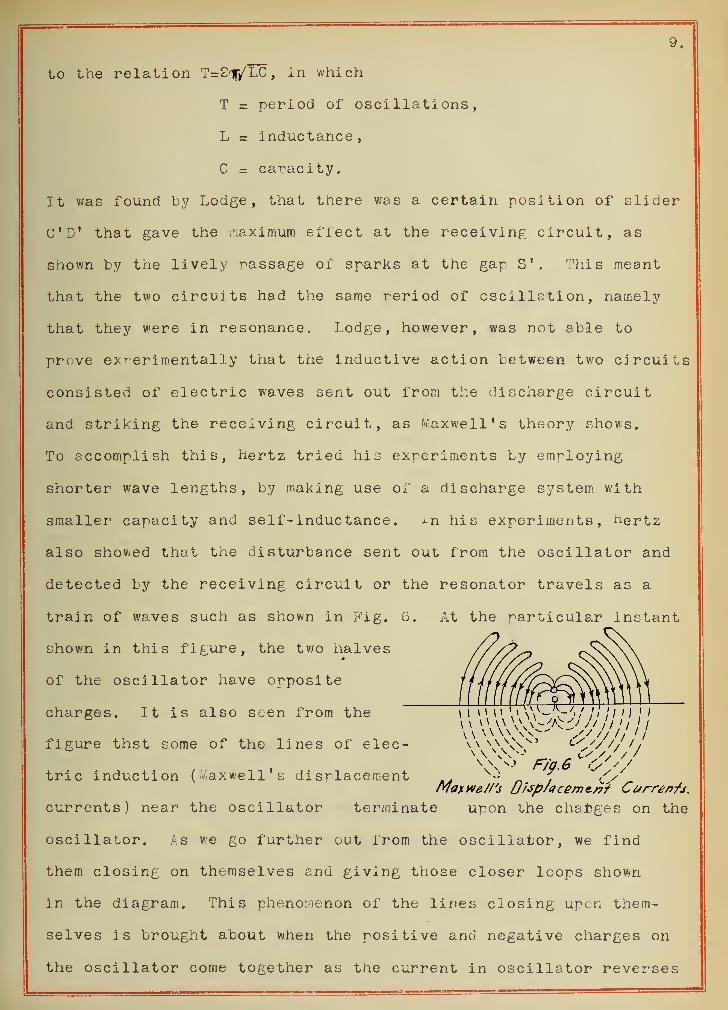
To accomplish this, Hertz tried his experiments by employing
shorter wave lengths, by making use of a discharge system with
smaller capacity and self-inductance . xn his experiments, ne rtz
also showed that the disturbance sent out from the oscillator and
detected by the receiving circuit or the resonator travels as a
train of waves such as shown in Fig. 6. At the particular instant
shown in this figure, the two halves
of the oscillator have opposite
charges. It is also seen from the
figure thst some of the lines of elec-
SnVj F/g.6'O'
trie induction (Maxwell s displacement 4 ;/y7axtve//<s u/sp/tcement Currents.
currents) near the oscillator terminate upon the changes on the
oscillator. is we go further out from the oscillator, we find
them closing on themselves and giving those closer loops shown
in the diagram. This phenomenon of the lines closing upon them-
selves is brought about when the positive and negative charges on
the oscillator come together as the current in oscillator reverses
\\\0> C/ //////
\V-> r/p.6 o//
10.in direction.
For rroving Maxwell's theory by experiments within the
confines of the laboratory, as has been mentioned, it was necessary
to have much shorter wave lengths than those obtained by Maxwell
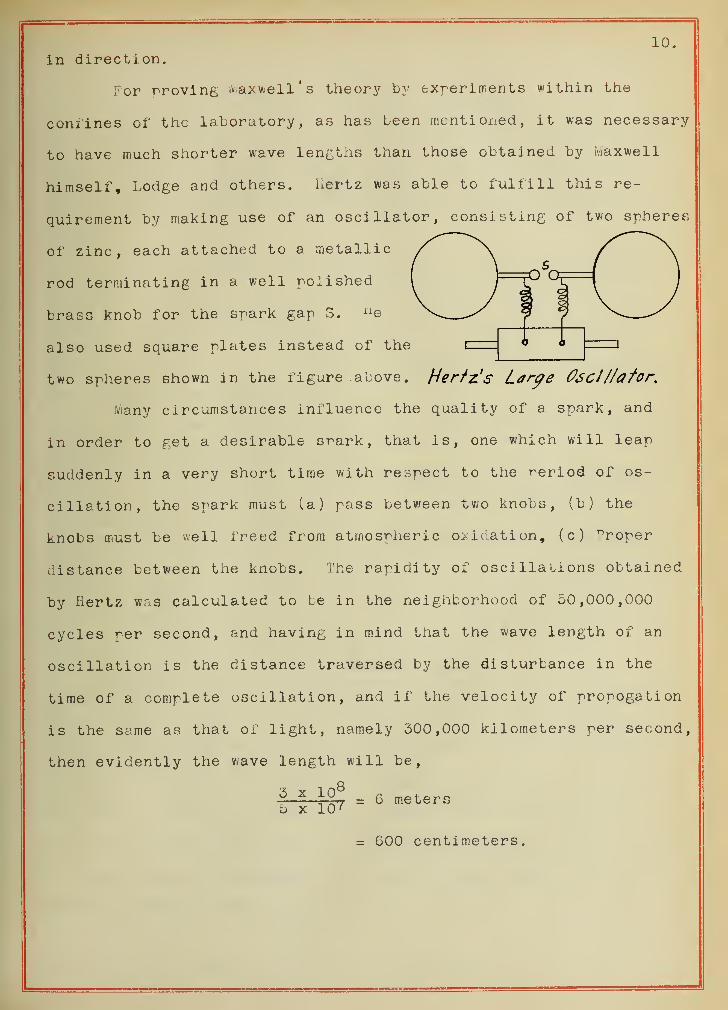
himself, Lodge and others. liertz was able to fulfill this re-
quirement by making use of an oscillator, consisting of two spheres
of zinc, each attached to a metallic
rod terminating in a well polished
brass knob for the spark gap S. ue
also used square plates instead of the
two spheres shown in the figure above. Hertz's Large 06cl//afort
Many circumstances influence the quality of a spark, and
in order to get a desirable srark, that is, one which will leap
suddenly in a very short time with respect to the reriod of os-
cillation, the spark must (a) pass between two knobs, (b) the
knobs must be well freed from atmospheric oxidation, (c) ^roper
distance between the knobs. The rapidity of oscillations obtained
by Hertz was calculated to be in the neighborhood of 50,000,000
cycles per second, and having in mind that the wave length of an
oscillation is the distance traversed by the disturbance in the
time of a complete oscillation, and if the velocity of prorogation
is the same as that of light, namely 300,000 kilometers per second,
then evidently the wave length will be,
3 x j-QS = 6 metersb x 107
=a GOO centimeters.
11.
111.
EVOLUTION OF WIRELESS SIGNALIIG.
Having studied somewhat the nature of the electric waves,
we now proceed to some of the primitive attempts, which gradually
led to the development of the wireless telegraphy as we have it
today.
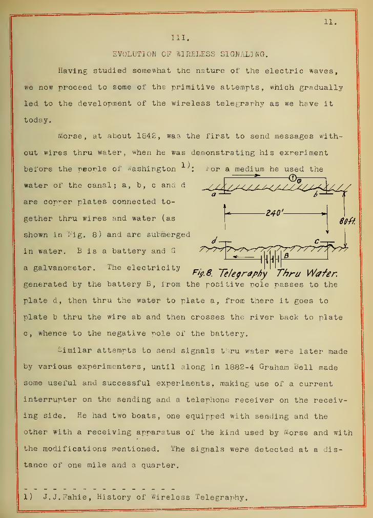
Morse, at about 1842, was the first to send messages with-
out wires thru water, when he was demonstrating his experiment
1). ior a medium he used the%
lift
Fi?.8. Te/egrapfry Thru Wafer.
before the people of Washington
water of the canal; a, b, c and d
are copper plates connected to-
gether thru wires Find water (as
shown in fig. 8) and are submerged
in water. B is a battery and G
a galvanometer. The electricity
generated by the battery B, from the positive pole passes to the
plate d, then thru the water to plate a, from there it goes to
plate b thru the wire ab and then crosses the river back to plate
c, whence to the negative -nole of the battery.
similar attempts to send signals thru water were later made
by various experimenters, until along in 1882-4 Graham Bell made
some useful and successful experiments, making use of a current
interrupter on the sending and a telephone receiver on the receiv-
ing side. He had two boats, one equipped with sending and the
other with a receiving apparatus of the kind used by worse and with
the modifications mentioned. The signals were detected at a dis-
tance of one mile and a quarter.
. 1) J.J.Fahie, History of Wireless Telegraphy.
12.
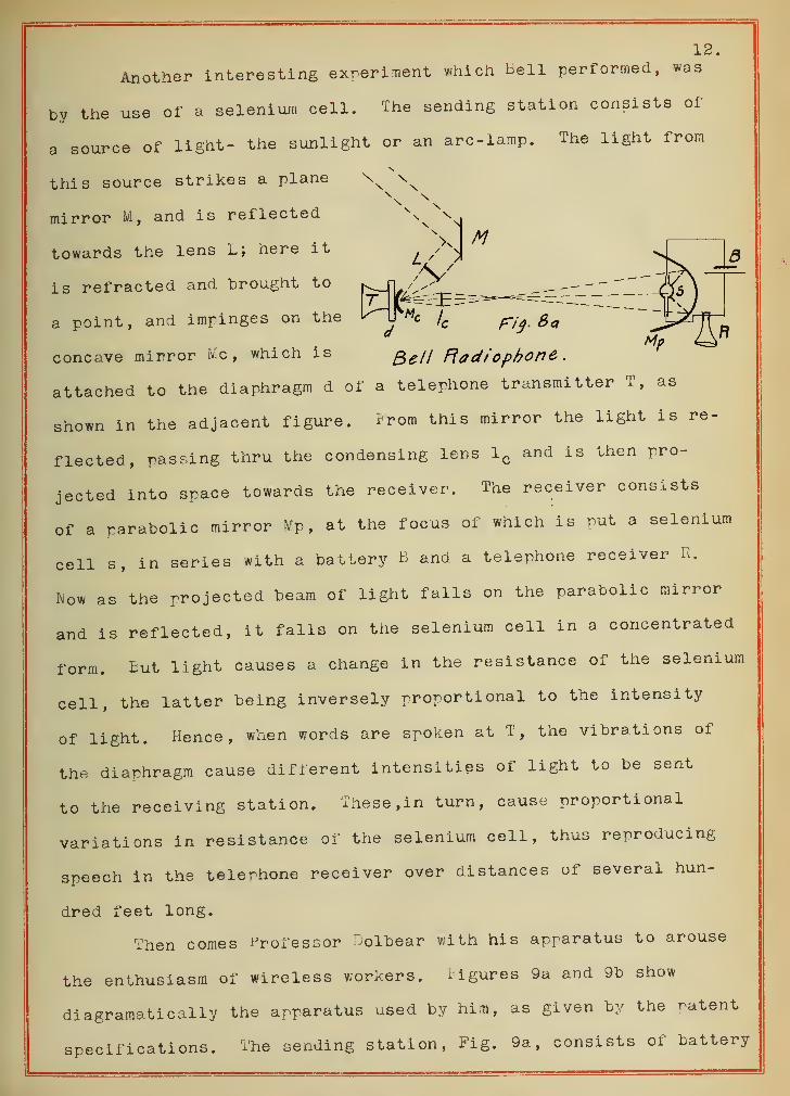
Another interesting experiment which Bell performed, was
by the use of a selenium cell. The sending station consists of
a source of light- the sunlight or an arc-lamp. The light from
this source strikes a plane
mirror M , and is reflectedss
M
Tn ^towards the lens L; here it
is refracted and brought to
a point, and impinges on the
concave mirror He, which is ge /i Radiophone
attached to the diaphragm d of a telephone transmitter T, as
shown in the adjacent figure. From this mirror the light is re-
flected, passing thru the condensing lens 1Q
and is then pro-
jected into space towards the receiver. The receiver consists
of a parabolic mirror Hp, at the focus of which is put a selenium
cell s, in series with a battery B and a telephone receiver R.
ftow as the projected beam of light falls on the parabolic mirror
and is reflected, it falls on the selenium cell in a concentrated
form. But light causes a change in the resistance of the selenium
cell, the latter being inversely proportional to the intensity
of light. Hence, when words are spoken at T, the vibrations of
the diaphragm cause different intensities of light to be sent
to the receiving station. These, in turn, cause proportional
variations in resistance of the selenium cell, thus reproducing
speech in the telephone receiver over distances of several hun-
dred feet long.
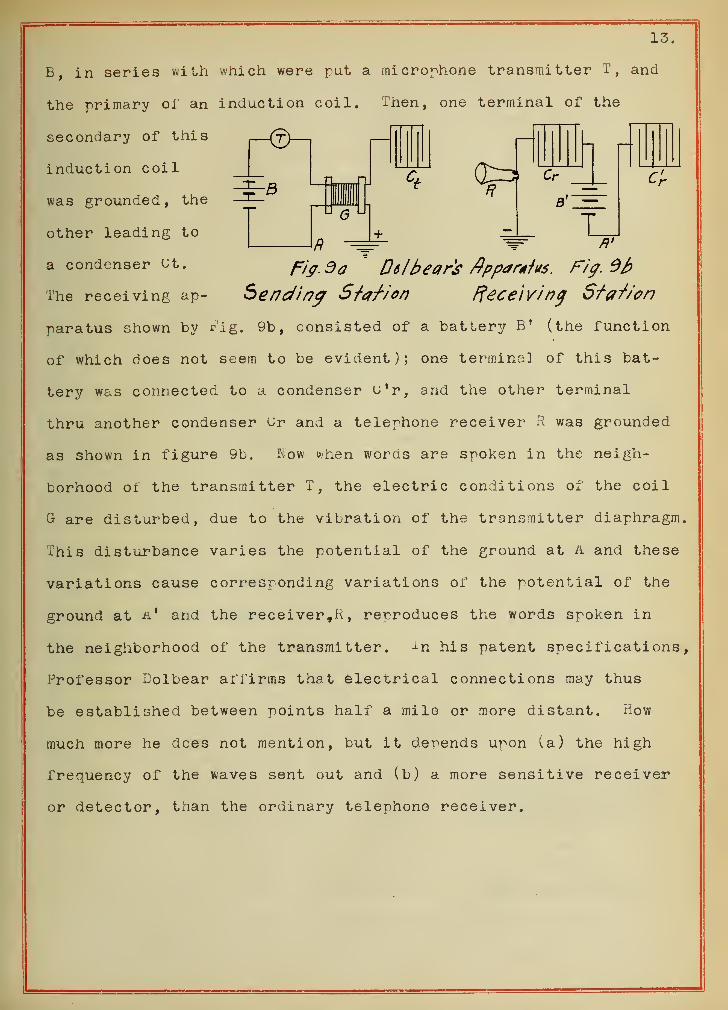
Then comes Professor Dolbear with his apparatus to arouse
the enthusiasm of wireless workers. Figures 9a and 9b show
diagramatically the apparatus used by him, as given by the latent
specifications. The sending station, Fig. 9a, consists of battery
13.
B, in series with which were put a microphone transmitter T, and
the primary of an induction coil. Then, one terminal of the
secondary of this
induction coil
was grounded, the
other leading to
a condenser ^t.
The receiving ap-
0^3 Cr
G
R— +
A'
/v>. 3a Delbears Apparatus. Fig. Ob
Sending Sfaf/on Receiving S-faJ/'on
paratus shown by rig. 9b, consisted of a battery B' (the function
of which does not seem to be evident); one terminal of this bat-
tery was connected to a condenser u'r, and the other terminal
thru another condenser (Jr and a telephone receiver R was grounded
as shown in figure 9b. Sow when words are spoken in the neigh-
borhood of the transmitter T, the electric conditions of the coil
G are disturbed, due to the vibration of the transmitter diaphragm.
This disturbance varies the potential of the ground at a and these
variations cause corresponding variations of the potential of the
ground at &' and the receiver, R, reproduces the words spoken in
the neighborhood of the transmitter. in his patent specifications,
Professor Dolbear affirms that electrical connections may thus
be established between points half a mile or more distant. How
much more he dees not mention, but it depends upon (a) the high
frequency of the waves sent out and (b) a more sensitive receiver
or detector, than the ordinary telephone receiver.
IV.14.
OSCILLATIONS OF HIGH FREQUENCY
.
Tracing rather hurriedly the developments of wireless tele-
graphy in the previous chapter, we came to the roint where signals
could be sent for distances of about a mile or so. New the
question arises as to sending signals or messages for distances
much further than a mile and also to detect waves coming from
such distances.
To do this, there are two principal difficulties to over-
come, namely:
(a) The production of oscillations of a high frequency, and
(b) A more sensitive detector must be provided on the re-
ceiving end. From the results obtained by a large number of
oscillators, we have made the following table:
Name of Oscillator.
Blondlot
Large oscillator by Hertz
Small oscillator by Hertz
Ri ghi
J. C. Bose
Wave lengthin meters.
30.
6.
.6
.10
.006
Vibrations -per
second.
10,000,000
50,000,000
500,000,000
3,000,000,000
50,000,000,000
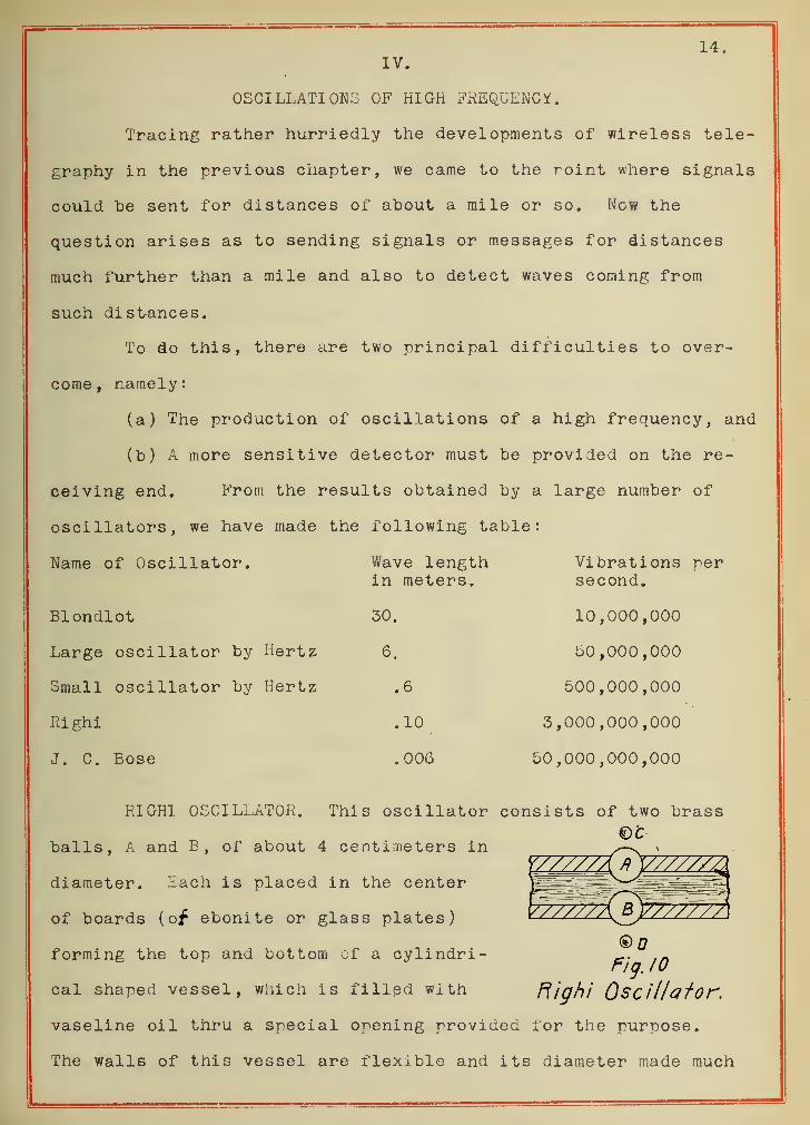
RI GHI OSCILLATOR. This oscillator consists of two brass€>t~
balls, A and B, of about 4 centimeters in
diameter. Xach is placed in the center
of boards (of ebonite or glass plates)
forming the top and bottom of a cylindri-
cal shaped vessel, which is filled with
®0Pig. 10
Right Oscillator.
vaseline oil thru a special opening provided for the purpose.
The walls of this vessel are flexible and its diameter made much
15
greater than its height. For charging these spheres, the two
smaller spheres C and D were connected to the poles of a Uoltz
static machine. There were no conductors between C and A or
between u and B. Having the proper sracings between the four
spheres, three sparks were produced, the one in the middle, be-
tween AB, being oscillatory in character, the two other sparks
being there only for charging the spheres A and B. For inter-
rupting the curvent a Morse key was used.
The receiving station consisted of a local battery circuit,
having an ordinary telegraphic receiver and a tube containing
some conductive grains in its middle part, held there by means
of a metallic plate on each end, which in turn were connected
to conductors leading out from the ends of the tube.
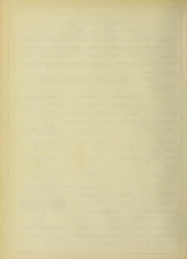
As seen from the table above, Bose has been able to obtain
a frequency of 50,000,000 cycles per second. For this experiment
he used three hollow spheres, A, B and 0., the two outside ones
being connected to the poles of a
Ruhmkorff coil, and the middle
one is insulated. L is a cylindri-
cal lens for concentrating the F/'q.ll. dose's Osci/lafor
radiation. Also instead of operating his coil with a vibrating
interrupter, he uses a handbreak for the sake of economy of the
electrodes. Then his charge thus obtained- in air- is oscillat-
ory. The detector used by him is based on the principle of the
Brady coherer, or radiocoherer , with some modifications.
There are other methods of sending signals besides making
use of the spark discharge of a condenser and for convergence
we shall divide them into the following three groups:
Signals obtained by:
k
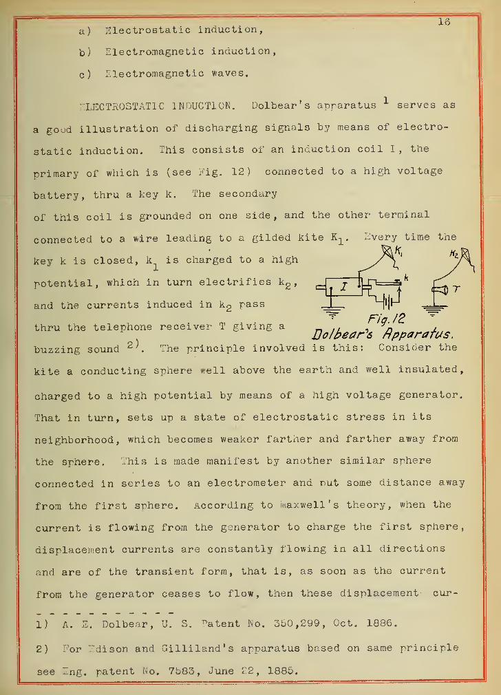
16a) Electrostatic induction,
b) Electromagnetic induction,
c) Electromagnetic waves.
ELECTROSTATIC INDUCTION. Dolbear's apparatus 1 serves as
a good illustration of discharging signals by means of electro-
static induction. This consists of an induction coil I, the
primary of which is (see Fig. 12) connected to a high voltage
battery, thru a key k. The secondary
of this coil is grounded on one side, and the other terminal
connected to a wire leading to a gilded kite K-^ Evej"y time the
key k is closed, k^ is charged to a high
potential, which in turn electrifies kg,
and the currents induced in kg pass
m , <Fig /2
^thru the telephone receiver T giving a
JJo/bear^S Apparatusbuzzing sound 2 K The principle involved is this: Consider the
kite a conducting sphere well above the earth and well insulated,
charged to a high potential by means of a high voltage generator.
That in turn, sets up a state of electrostatic stress in its
neighborhood, which becomes weaker farther and farther away from
the sphere. This is made manifest by another similar sphere
connected in series to an electrometer and nut some distance away
from the first sphere. According to maxwell's theory, when the
current is flowing from the generator to charge the first sphere,
displacement currents are constantly flowing in all directions
and are of the transient form, that is, as soon as the current
from the generator ceases to flow, then these displacement cur-
1) A. E. Dolbear, U. S. ^atent No. 350,299, Oct. 1886.
2) For Edison and Gilliland's apparatus based on same principle
see Eng. patent No. 7583, June 22, 1885.
17rents also cease to flow and we have a state of affairs known as
the electrostatic field, which represents energy and is given
to the receiving station as such.
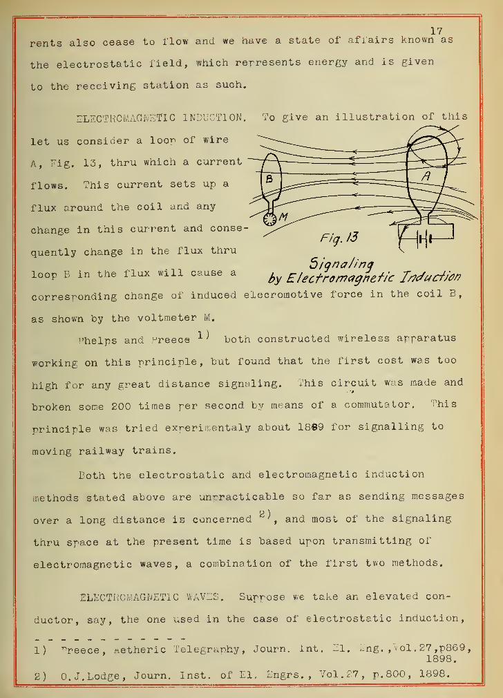
ELECTROMAGNET! C I NDUCTI ON
.
let us consider a loon of wire
A, Tig. 13, thru which a current
flows. This current sets up a
flux around the coil and any
change in this current and conse-
quently change in the flux thru
loop B in the flux will cause a
To give an illustration of this
Signalingby Electromagnetic frtc/ucf/on
corresponding change of induced elecroinoti ve force in the coil B,
as shown by the voltmeter M.
"helps and Greece 1^ both constructed wireless apparatus
working on this principle, but found that the first cost was too
high for any great distance signaling. This circuit was made and
broken some 200 times per second by means of a commutator. This
principle was tried experimentaly about 1889 for signalling to
moving railway trains.
Both the electrostatic and electromagnetic induction
methods stated above are unpracticable so far as sending messages
2 )
over a long distance is concerned ', and most of the signaling
thru space at the present time is based upon transmitting of
electromagnetic waves, a combination of the first two methods.
ELECTROMAGNETIC WAVES. Suppose we take an elevated con-
ductor, say, the one used in the case of electrostatic induction,
1) ^reece, .netheric Telegraphy, Journ. int. El. Lng. ,Vol.27,p869,1898.
2) O.J.Lodge, Journ. Inst, of LI. Engrs.,Vol.27, p. 800, 1898.
18
and pass a current of a very high frequency thru it by means of
an alternator instead of the direct current generator used above.
At the moment when the alternator gives its maximum voltage to
the conductor, we shall have the case of electrostatic condition,
that is, the whole surrounding field will be in a state of elect-
rostatic stress, or electrical displacement as maxwell ts it.
as soon as the voltage of the alternator goes to during the
cycle, the conductor discharges itself thru the wire to the ground.
This results in the displacement currents flowing back to the
elevated conductor. While this is going on, the current flowing
from the conductor to the ground sets up an electromagnetic field
around the conductor. ^hen the latter is completely discharged
at the instant the current in the wire is a maximum, we find that
the electrostatic field in the neighborhood of the oscillator is
replaced by an electromagnetic field. Maxwell's theory 1^ shows
that as a magnetic field is created when a current flows in a
conductor, so it is created when displacement currents flow.
Then whenever the electrostatic field is varying the magnetic
field goes with it, and their magnetic force spreads out larger
and larger in the form of waves, as do the water waves of a pond
when a stone is thrown into it.
1) J. A. Fleming, Principles of El, ^ave Telegr. and Telephony, P339.
19
V.
METHODS OF OBTAINING ELECTRIC WAVES.
Come of the recent methods of exciting electric waves,
*hich are widely used in wireless telegraphy , will now be described.
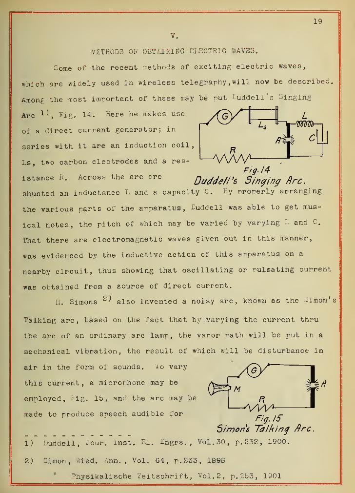
Among the most important of these may be put Duddell's Singing
Arc Fig. 14. Here he makes use
of a direct current generator; in
series with it are an induction coil,
Ls, two carbon electrodes and a res-
istance R. Across the arc are
AAAAAFig. 14
Duddell's Singing fire.
shunted an inductance L and a capacity C. By properly arranging
the various parts of the apparatus, IHiddell was able to get mus-
ical notes, the pitch of which may be varied by varying L and C.
That there are electromagnetic waves given out in this manner,
was evidenced by the inductive action of this apparatus on a
nearby circuit, thus showing that oscillating or pulsating current
was obtained from a source of direct current.
II. Simons 2 ^ also invented a noisy arc, known as the Simon's
Talking arc, based on the fact that by. varying the current thru
the arc of an ordinary arc lamp, the vapor path will be put in a
mechanical vibration, the result of which will be disturbance in
air in the form of sounds. io vary
this current, a microphone may be
employed, I ig. lb, an J the arc may be
made to produce speech audible forF/g. IS
Simon's Talking fire.
1) Duddell, Jour. Inst. El. Engrs. ,Vol.30, p. 232, 1900.
2) Simon, v.ied. Ann., Vol. G4 , p. 233, 1898
" ^hysikalische Zeitschrift, Vol.2, p. £53, 1901
20several meters.
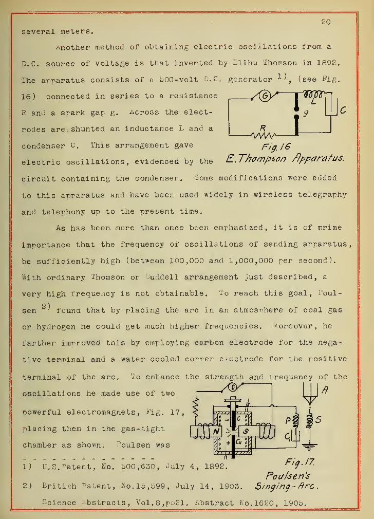
Another method of obtaining electric oscillations from a
D. C. source of voltage is that invented by L.lihu Thomson in 1892.
The apparatus consists of a 500-voit D. G. generator 1^ , (see Fig.
16) connected in series to a resistsnce( /X&y*
R
Twrtnn
R and a srark gap g. across the elect-
rodes are shunted an inductance L and a
condenser 0. This arrangement gave Fig. 16
electric oscillations, evidenced by the E.Thompson Apparatus.
circuit containing the condenser. Some modifications were added
to this apparatus and have been used widely in wireless telegraphy
and telephony up to the present time.
As has been, more than once been emphasized, it is of prime
importance that the frequency of oscillations of sending apparatus,
be sufficiently high (between 100,000 and 1,000,000 per second).
Hith ordinary Thomson or Duddell arrangement just described, a
very high frequency is not obtainable. To reach this goal, Poul-
2 )
sen ; found that by placing the arc in an atmosphere of coal gas
or hydrogen he could get much higher frequencies. Moreover, he
farther improved this by employing carbon electrode for the nega-
tive terminal and a water cooled copper electrode for the positive
terminal of the arc. To enhance the strength and i requency of the
oscillations he made use of two - - —
«
powerful electromagnets, Fig. 17,
placing them in the gas-tight
chamber as shown. ^oulsen was
1) U.S. latent , No. 500,630, July 4, 1892. Big, 17.
Pou/sen's2) British Patent, No. 15,599, July 14, 1903. Singing- fire
.
Science -bstracts, Vol.8,po21. Abstract Ko.1620, 1905.
21
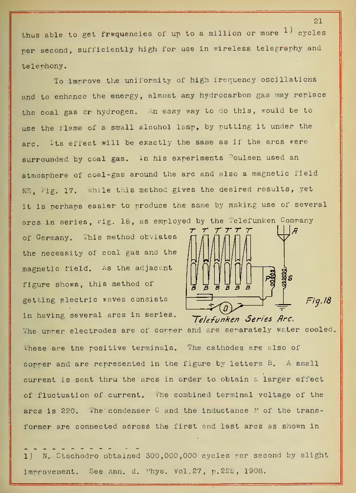
1)thus able to get frwquencies of up to a million or more x
> cycles
per second, sufficiently high for use in wireless telegraphy and
telephony.
To improve the uniformity of high frequency oscillations
and to enhance the energy, almost any hydrocarbon gas may replace
the coal gas cr hydrogen. An easy way to do this, would be to
use the 1 lame of a small alcohol lamp, by putting it under the
arc. its effect will be exactly the same as if the arcs were
surrounded by coal gas. in his experiments noulsen used an
atmosphere of coal-gas around the arc and also a magnetic field
NS, Fig. 17. Shile this method gives the desired results, yet
it is perhaps easier to produce the same by making use of several
arcs in series, f'ig. 18, as employed by the Telefunken Company
T T T TT Tof Germany. This method obviates jj~
the necessity of coal gas and the
magnetic field. As the adjacent
figure shows, this method of
getting electric waves consists
in having several arcs in series.-j-elefanken Series Arc.
The upper electrodes are of comer and are separately water cooled,
ihese are the positive terminals. The cathodes are also of
copper and are represented in the figure by letters B, A small
current is sent thru the arcs in order to obtain a larger effect
of fluctuation of current. fhe combined terminal voltage of the
arcs is 220. The condenser C and the inductance P of the trans-
former are connected across the first and last arcs as shown in
J_ Fig. 18
1) N. Gtschodro obtained 300,000,000 cycles rer second by slight
improvement. See Ann. d. Phys. Vol.27, p. 225, 1908.
22
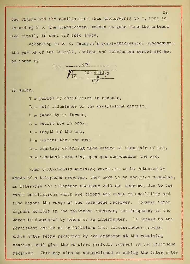
the figure and the oscillations thus transferred to P, then to
secondary S of the transformer, whence it goes thru the antenna
and finally is sent off into space.
According to G. If. Nasmyth's qua si- theoretical discussion,
the period of the Duddell, ?oulsen and Telefunken series arc may
be round bym 2fT
71 (H- c+ld ,gLC _ A
"4L2"
in which,
T = period of oscillation in seconds,
L = self-inductance of the oscillating circuit,
C = capacity in farads,
h = resistance in ohms,
1 - length of the arc,
A = current thru the arc,
c = constant depending upon nature of terminals of arc,
d = constant depending upon gas surrounding the arc.
Ahen continuously arriving waves are to be detected by
means of a telephone receiver, they have to be modified somewhat,
as otherwise the telephone receiver will not resrond, due to the
rapid oscillations which are beyond the limit of audibility and
also beyond the range of the telephone receiver. To make these
signals audible in the telephone receiver, the frequency of the
waves is decreased by means of an interrupter. it breaks up the
persistent series of oscillations into discontinuous groups,
which after being rectified by the detector at the receiving
station, will give the required periodic current in the telephone
receiver. This may also be accomplished by making the interrupter
\
yf(
',n+e.rrupter
1
ft
23
at the sending station throw an inductance in or out of the cir-
cuit. This will produce a periodic strengthening and weakening
of the effects received making them audible.
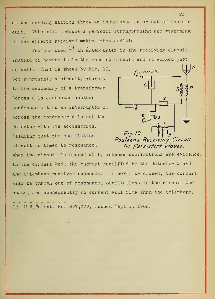
Poulsen used ^ an unterrup ter in the receiving circuit
instead of having it in the sending circuit and it worked just
as well. This is shown by tig. 19,
Scd represents a circuit, where S
is the secondary of a transformer.
Across c is connected another
condenser k thru an interrupter f.
Across the condenser d is rut the
detector with its accessories.
Assuming that the oscillation
circuit is timed to resonance,
when the circuit is opened at f, intense oscillations are evidenced
in the circuit Scd, the current rectified by the detector 3 and
the telephone receiver responds. if now f be closed, the circuit
will be thrown out of resonance, oscillations in the circuit 3cd
cease, and consequently no current will flow thru the telephone.
e
I vJvvvvvvvv
Fig. 19 HH'V.
Poulsen's Receiving Circuii
for Persistent Waves .
1) U.S. Patent, No. 897,779, issued oept 1, 1908.
24.
VI.
THE RECEIVING STATION.
One of the most essential parts of a receiving station is
the detector, by means of which waves sent from the sending station
are detected.
The detectors now in market are of various tyres; they may
(roughly) be classed as follows:
1. Coherers.
2. Thermal detectors.
3. magnetic detectors.
4. Crystal rectifiers.
5. Vacuum detectors.
6. electrolytic detectors.
7. mechanical detectors.
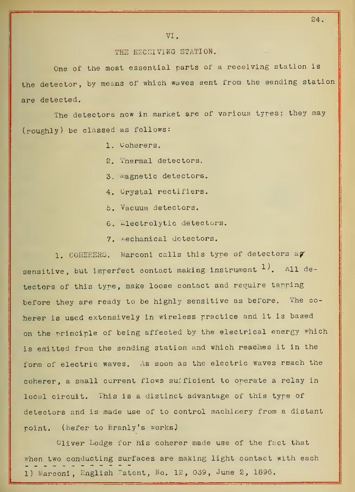
1. COHERERS. Marconi calls this tyre of detectors a§r
sensitive, but imperfect contact making instrument All de-
tectors of this type, make loose contact and require tapping
before they are ready to be highly sensitive as before. The co-
herer is used extensively in wireless practice and it is based
on the principle of being affected by the electrical energy which
is emitted from the sending station and which reaches it in the
form of electric waves. As soon as the electric waves reach the
coherer, a small current flows sufficient to operate a relay in
local circuit. This is a distinct advantage of this type of
detectors and is made use of to control machinery from a distant
point. (Refer to Branly's works )
Oliver Lodge for his coherer made use of the fact that
when two conducting surfaces are making light contact with each
1) Marconi, English Patent, No. 12, 039, June 2, 1896.
25.
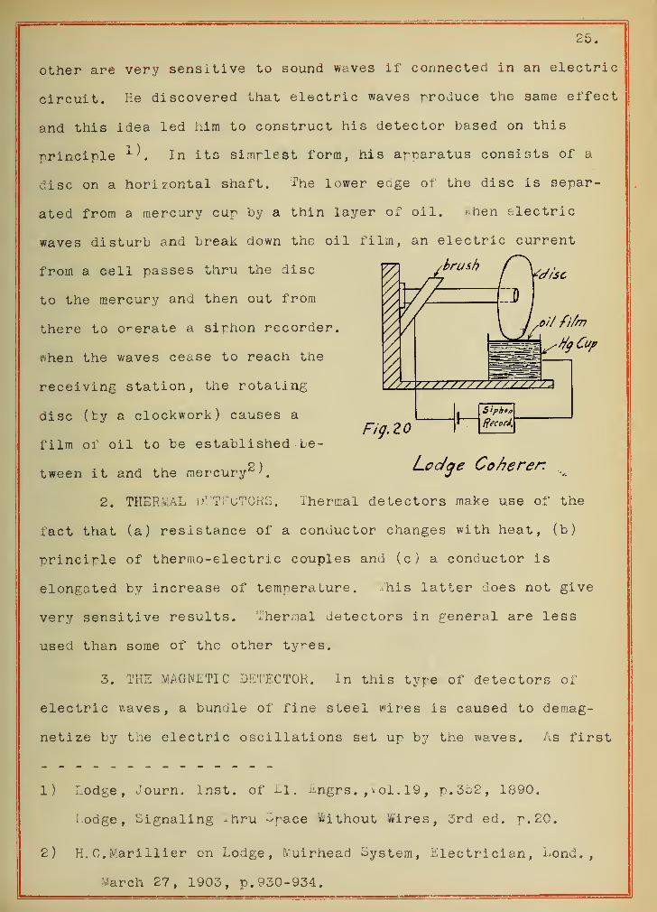
other are very sensitive to sound waves if connected in an electric
circuit. He discovered that electric waves produce the same effect
and this idea led him to construct his detector based on this
principle In its simplest form, his apparatus consists of a
disc on a horizontal shaft. The lower edge of the disc is separ-
ated from a mercury cup by a thin layer of oil. * hen electric
waves disturb and break down the oil film, an electric current
from a cell passes thru the disc
to the mercury and then out from
there to operate a siphon recorder,
when the waves cease to reach the
receiving station, the rotating
disc (by a clockwork) causes a
film of oil to be established te-
tween it and the mercury"''.
2. THER.WhL dETEuTORS. Thermal detectors make use of the
fact that (a) resistance of a conductor changes with heat, (b)
principle of thermo-electric couples and (c) a conductor is
elongated by increase of temperature. i'his latter does not give
very sensitive results. iher<Tial detectors in general are less
used than some of the other tyres.
3. THE MAGNETIC DETECTOR. in this type of detectors of
electric v.aves, a bundle of fine steel wires is caused to demag-
netize by the electric oscillations set up by the waves. As first
1) Lodge, Journ. Inst, of El. Engrs. , vol. 19 , p. 352, 1890.
1 odge,Signaling ~hru ^pace Without Wires, 3rd ed. p. 20.
2) K. 0. iVarillier on Lodge, Muirhead System, Electrician, Lond.,
arch 27, 1903, p. 930-934.
Fig. 20
26.
used by Rutherford 1^ this bundle consisted of some twenty pieces
of wire, each 1 era. long and .007 cm. in diameter and insulated
from each other by shellac. It was magnetized by a magnet, "dien
electric oscillations were passed thru the coil of some eighty
turns, the wires of the bundle placed in the middle of this coil
lost some of their magnetism, shown by a diminished deflection
of a magnetometer. Rutherford found that by connecting the coil
mentioned to a resonator, electric waves from a small hertz os-
cillator could be detected for some half a mile.
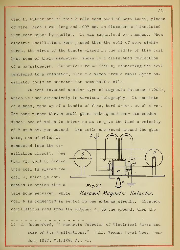
Marconi invented another type of magnetic detector (1902),
which is used extensively in wireless telegraphy. It consists
of a band, made up of a bundle of fine, hard-drawn, steel wires.
The band passes thru a small glass tube g and over two wooden
discs, one of which is driven so as to give the band a velocity
of 7 or 8 cm. per second. Two coils are wound around the glass
tube, one of which is
connected into the os-
cillation circuit. See
Fig. 21, coil b. Around
this coil is placed the
coil C, which is con-
nected in series with a Fig. 2.1
telephone receiver, while Marconi Magnetic Detector,
coil b is connected in series in one antenna circuit. Electric
oscillations pass from the antenna A, to the ground, thru the
1) E. Rutherford, "A Magnetic Detector d Electrical Slaves and
some of its Applications." Phil. Trans. Royal Soc. , Lon-
don, 1897, Vol.189, A., pi.
£7.
coil b, which is sometimes called the oscillation coil. Two mag-
nets are placed above this coil so as to form magnetic roles in
other one (south role in the illustration) within it. Considering
a point on the moving band, it becomes a ft pole outside the coils,
changes to a S pole within the coils and becomes again a N pole
after issuing from the coils. While moving within the coil, this
point is subjected to different degrees of magnetization, so that
magnetic condition is filled with respect to .the magnetizing
magnets. This gives a steady state of magnetization within the
coil and produces no inductive effect in the form of current in
the telephone circuit. If now a train of electric oscillations
rasses thru the oscillation coil b, the magnetic state. within the
coil will be changed, which in turn causes electromotive force
Lo be induced in the coil c and the telephone gives a click. A
series of trains of electric oscillations gives a series of clicks,
producing a musical note with a pitch depending on the frequency
of arrival of the trains, which frequency is also that of the
sparks of the sending station.
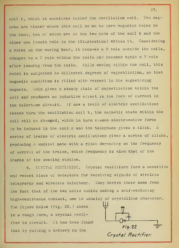
4. CRYSTAL RECTIFIERS. Crystal rectifiers form a sensitive
and recent class of detectors for receiving signals of wireless
telegraphy and wireless telephony. They derive their name from
the fact that of the two solid bodies making a self-restoring
high-resistance contact, one is usually of crystalline character.
The figure below (Fig. 22. ) shows V «=.
the bandI two of which are at the two ends of the coil b and the
in a rough form, a crystal recti-
fier in circuit. it has been found
that by putting a battery in theFig. 22
Crystal Rectifier.
28.
circuit as shown, often highly increases its sensitiveness." These
detectors depend for their action on the rectifying and thermo-
electric qualities of various crystals, such as carborundum
,
galena, silicon, molybdenite, etc.
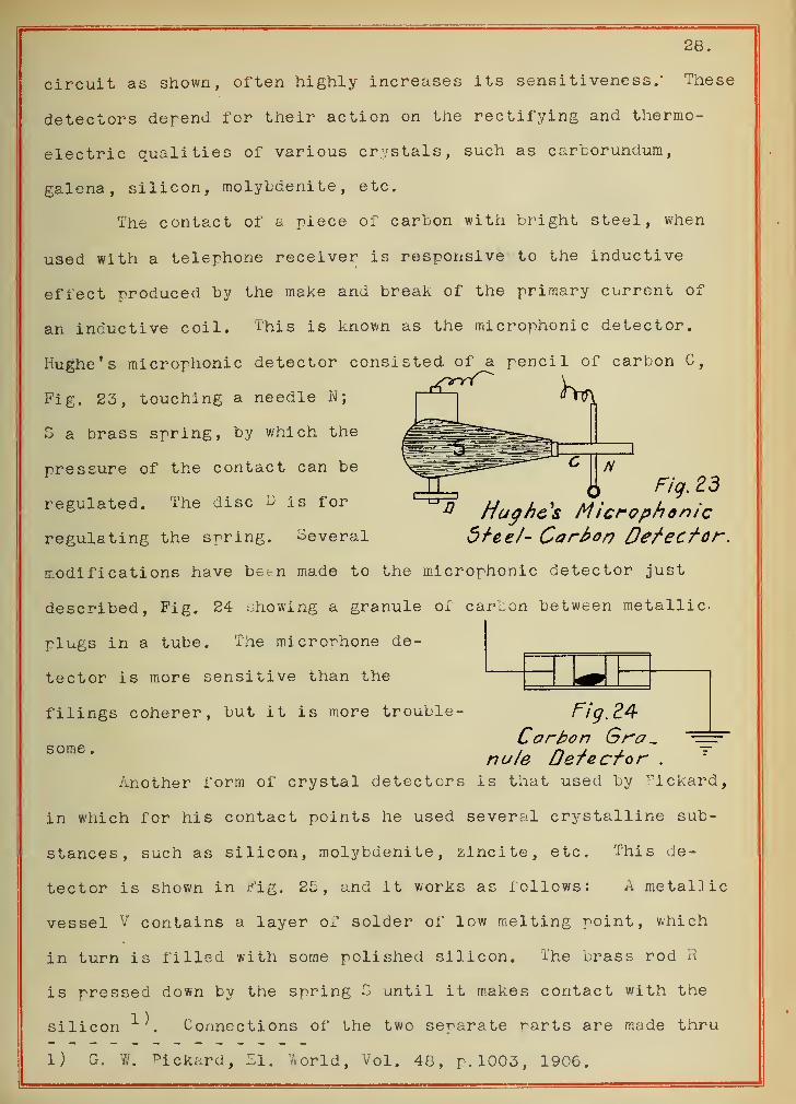
The contact of a piece of carbon with bright steel, when
used with a telephone receiver is responsive to the inductive
effect produced by the make and break of the primary current of
an inductive coil. This is known as the microphonic detector.
Hughe's microphonic detector consisted of a pencil of carbon C,
Fig. 23, touching a needle N;
3 a brass spring, by which the
pressure of the contact can be
regulated. The disc u is for
regulating the spring. Several
Fig. 23n Hughes Microphonic
dree/- Carbon Defector.
modifications have bet-n made to the microphonic detector just
described, Fig. 24 showing a granule of carbon between metallic-
plugs in a tube. The microrhone de-
tector is more sensitive than the
filings coherer, but it is more trouble-
some .
Fig. 24Carbon Gra_
nu/e Defecfor .
another form of crystal detectors is that used by Pickard,
in which for his contact points he used several crystalline sub-
stances, such as silicon, molybdenite, zincite, etc. This de-
tector is shown in Fig. 25, and it works as follows: A metallic
vessel V contains a layer of solder of low melting point, which
in turn is filled with some polished silicon. The brass rod R
is pressed down by the spring S until it makes contact with the
silicon ^. Connections of the two separate rarts are made thru
1) Gr. «(. Pickard, El. World, Vol. 48, p. 1003, 1906.
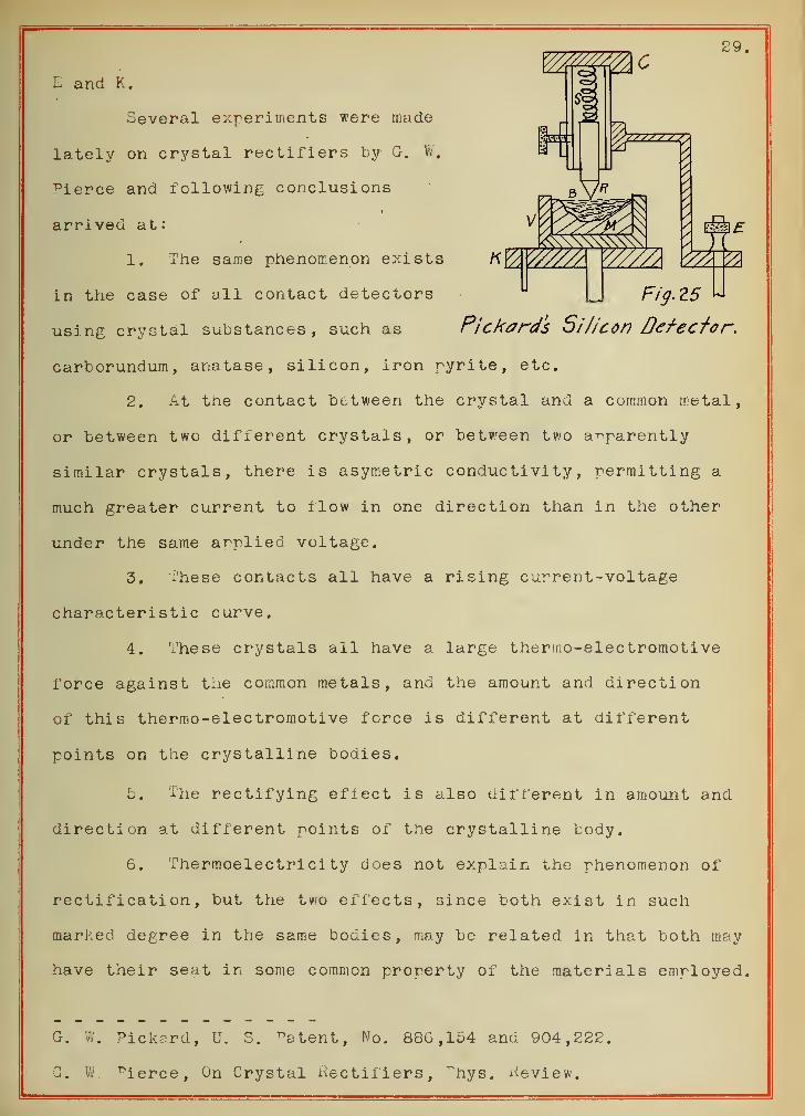
U Fig.Z5 W
Pjckard's Si/icon Defector.
29
L and K.
Several experiments were made
lately on crystal rectifiers by G. W.
pierce and following conclusions
arrived at:
1. The same phenomenon exists
in the case of all contact detectors
using crystal substances, such as
carborundum, anatase , silicon, iron pyrite, etc.
2. At the contact between the crystal and a common metal,
or between two different crystals, or between two apparently
similar crystals, there is asymetric conductivity, permitting a
much greater current to flow in one direction than in the other
under the same arplied voltage.
3. These contacts all have a rising current-voltage
characteristic curve.
4. These crystals all have a large thermo-elec tromotive
force against the common metals, and the amount and direction
of this thermo-elec tromotive force is different at different
points on the crystalline bodies.
5. The rectifying effect is also different in amount and
direction at different points of the crystalline body.
6. Thermoelectricity does not explain the phenomenon of
rectification, but the two effects , since both exist in such
marked degree in the same bodies, may be related in that both may
have their seat in some common property of the materials employed.
G. W. Pickard, U. S. ^atent, No. 886,154 and 904,222.
C. W rierce, On Crystal Rectifiers, Phys. Review.
30
7. i th crystal contact rectif iers the A. G. seems to be
converted into D.C.
n
o /77
i7
/=72 rning's VacuumTube Rectifier.
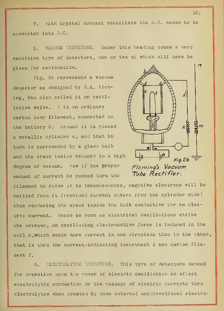
5. VACUUM DETECTORS. Under this heading comes a very
sensitive tyre of detectors, one or two of which will here be
given for explanation.
Fig. 26 represents a vacuum
detector as designed by J. A. Flem-
ing, who also called it an oscil-
lation valve. P is an ordinary
carbon lamp filament, connected to
the battery B. Around it is placed
a metallic cylinder c, and that in
turn is surrounded by a glass bulb
and the space inside reduced to a high
degree of vacuum. how if the proper
amount of current be passed thru the
filament to raise it to incandescence, negative electrons will be
emitted from it (provided current enters from the cylinder side)
thus rendering the space inside the bulb conductive for an elec-
tric current. Hence as soon as electrical oscillations strike
the antenna, an oscillating electromotive force is induced in the
coil k, which sends more current in one direction than in the other,
that is thru the current-indicating instrument 1 and carton fila-
ment f.
6. ELECTROLYTIC DETECTORS. This type of detectors depend
for operation upon the power of electric oscillation to efiect
electrolytic conduction or the passage of electric currents thru
electrolytes when created by some external unidirectional electro-
31.
motive force.
E. Aschkinass 1^ and L. de i 1 crest c
^ were some of the earli-
est investigators of this phenomenon. In 1898 A Neugschwender 3 )
divided a strip of silver placed on a glass plate in two parts,
by a very sharp cut. The two parts were then connected in series
with a galvanometer, telephone receiver and a battery. When the
glass was dry, no current would pass, since the silver plate was
cut in the middle. As soon as some moi stare was placed on the
glass, then a current passed. Thus, if electric waves fall uron
an antenna connected to the two parts of the divided strip of
silver, and set up oscillations across the gap, the current was
suddenly decreased and a sound was heard in the telephone receiver.
Ly the aid of a microscope it was observed that small "bridges"
or "trees" of silver filaments were produced by electrolysis
extending across the narrow gap. The operation of the oscillations
seems to be breaking up these bridges or trees of metal, and thus
suddenly reduce the current flowing across the gap.
There are several other forms of electrolytic detectors
also, which are more or less in use and give good results. Thus,
the Fessenden-Schloemilch4
^ electrolyte detector consists of a
cup filled with some electrolyte, usually 20$ nitric acid, tho
1) E. Aschkinass, Wied. Annalen, Vol.67, p. 842.
2) L. de Forest, "Electrolytic Receivers in wireless Telegraphy"
in the electrician, 1904, Vol. 54, p. 94.
3) A. Neugschwender , "A New Ifave Detector", lied. Annalen der
Physik, 1899, Vol.67, p. 430.
4) Fessenden, U. S. ^atent No. 727,331, filed April 1903.
Schloemilch, ^lektrotechni sche Zeitschrift, 1903 , Vol. 24 , p. 959
32.
almost any electroly ti cally conductive liquid, such as dilute
sulphuric acid, common salt solutions, caustic soda, etc., may
be used. A very fine platinum wire from one side and a platinum
or other metal from the other side serve for the two electrodes.
The latter are connected to the antenna wither directly or in-
ductively and rapidly oscillating electric currents are thus made
to traverse the cup of the detector.
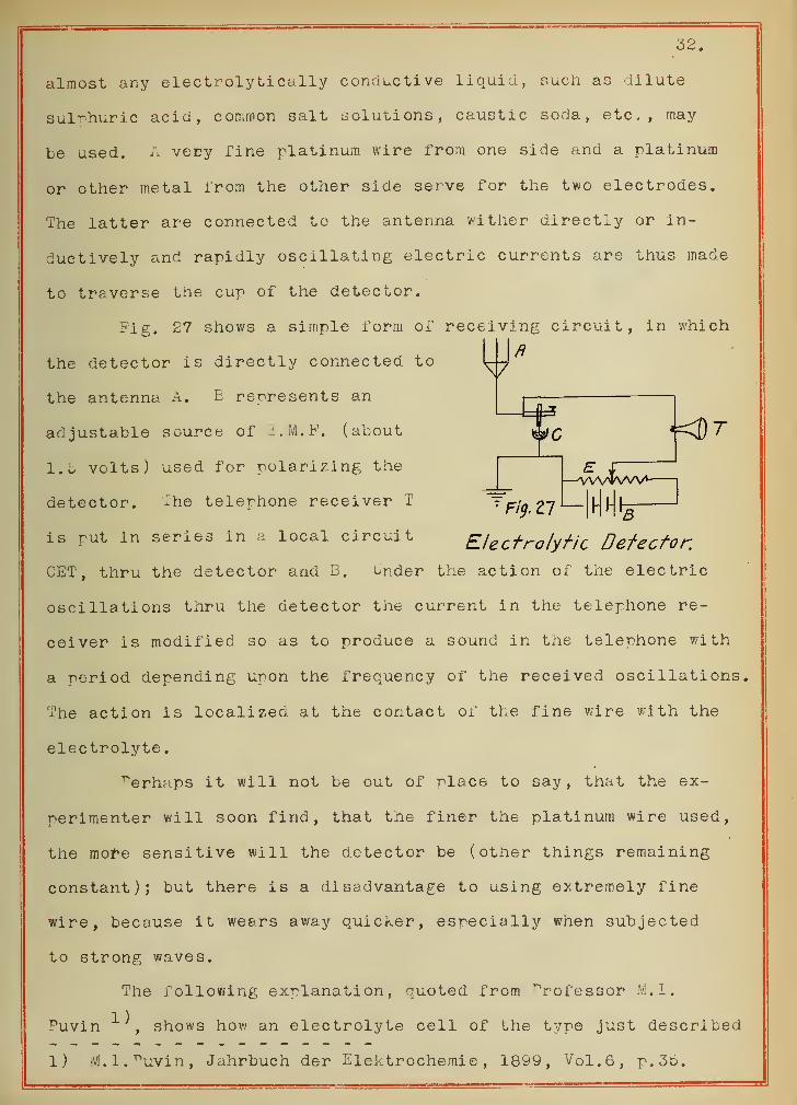
-ig. 27 shows a simple form of receiving circuit, in which
the detector is directly connected to 1
the antenna A. E represents an
adjustable source of S.M.F. (about
1.5 volts) used for polarizing the
detector. xhe telephone receiver T
is rut in series in a local circuit
—vvvtvvv1--
7Fig. 27 3
Electrolytic Detector.
GET, thru the detector and B. under the action of the electric
oscillations thru the detector the current in the telephone re-
ceiver is modified so as to produce a sound in the telephone with
a period depending upon the frequency of the received oscillations.
The action is localized at the contact of the fine wire with the
electrolyte
.
^erhaps it will not be out of place to say, that the ex-
perimenter will soon find, that the finer the platinum wire used,
the more sensitive will the detector be (other things remaining
constant); but there is a disadvantage to using extremely fine
wire, because it wears away quicker, especially when subjected
to strong waves.
The following explanation, quoted from ^rofessor M.I.
Puvin , shows how an electrolyte cell of the type just described
1) M. I. Puvin, Jahrbuch der Elektrochemie, 1899, Vol.6, p. 3b.
33.
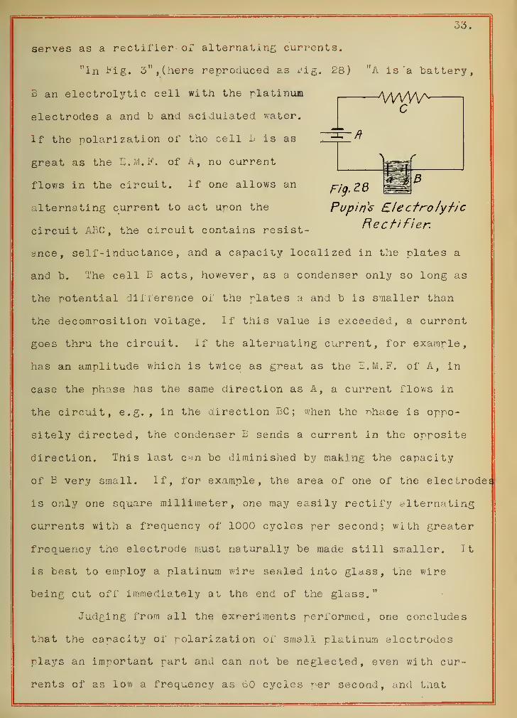
serves as a rectifier of alternating currents.
In Fig. 3", (here reproduced as si g. 28)itA i s 'a battery
,
B an electrolytic cell with the platinum AAAAY-electrodes a and b and acidulated water.
If the polarization of the cell B is as
great as the E . ! B .
flows in the circuit.
of a, no current
If one allows anFig. ?8
alternating current to act upon the Pupins Electro lytic
Rectifier.circuit ABC, the circuit contains resist-
ance, self-inductance , and a capacity localized in the plates a
and b. The cell B acts, however, as a condenser only so long as
the potential dil Terence of the plates a and b is smaller than
the decomposition voltage. If this value is exceeded, a current
goes thru the circuit. If the alternating current, for example,
has an amplitude which is twice as great as the E.M.F. of A, in
case the phase has the same direction as A, a current flows in
the circuit, e.g., in the direction BC ; when the phase is oppo-
sitely directed, the condenser B sends a current in the opposite
direction. This last can be diminished by making the capacity
of E very small. If, for example, the area of one of the electrodes
is only one square millimeter, one may easily rectify alternating
currents with a frequency of 1000 cycles per second; with greater
frequency the electrode must naturally be made still smaller. It
is best to employ a platinum wire sealed ixito glass, the wire
being cut off immediately at the end of the glass."
that the capacity of polarization of small platinum electrodes
plays an important part and can not be neglected, even with cur-
rents of as low a frequency as o0 cycles per second, and that
Judging from all the experiments performed, one concludes
34.
the whole phenomenon of the rectification of small currents by
means of the electrolytic detectors, may be explained on the basis
of the theory of electrolytic polarization.
7. MECHANICAL DETECTORS. These detectors are not of much
importance to warrant a discussion in the present work.
35.
VII.
ELECTRICAL RESONANCE.
In wireless apparatus usually means are provided to easily
adjust the receiving station to the desired wave lengths and to
exclude those from other sending stations. Those circuits which
are capable of being adjusted into resonance are known as syntonic
circuits. This condition is obtained when, in the equation
T?
1 = — ^
VW~+ (2*TL- 1 W2-rTfu )
2 fL = 2fTfC
that is, when the capacity and the inductance are so proportioned
that their reactances are equal.
a second method of greatly avoiding the undesirable effects
of waves coming from other stations than the one we care to com-
municate with, is accomplished by directing the radiation of the
transmitter toward the receiving station, just like the beam of
a search light 1^
.
Still another method employed for the purpose is to vary
the rate of interruption of the spark, thus giving the signals a
distinctive character, aside from their wave frequency.
:.ach of tnese methods has its particular advantages and
disadvantages and is widely used.
In its simplest form, the syntonic circuit includes an
inductance coil, placed between the antenna and the detector or
between the latter and the ground. This inductance or tuning
coil is made of a single layer of wire wound on an insulating
1) See "hysikali sche Zeitschrift, Vol.7, p. 302, 1906.
Also Bellini's and Tosi ' s Directive wireless Works.
36.
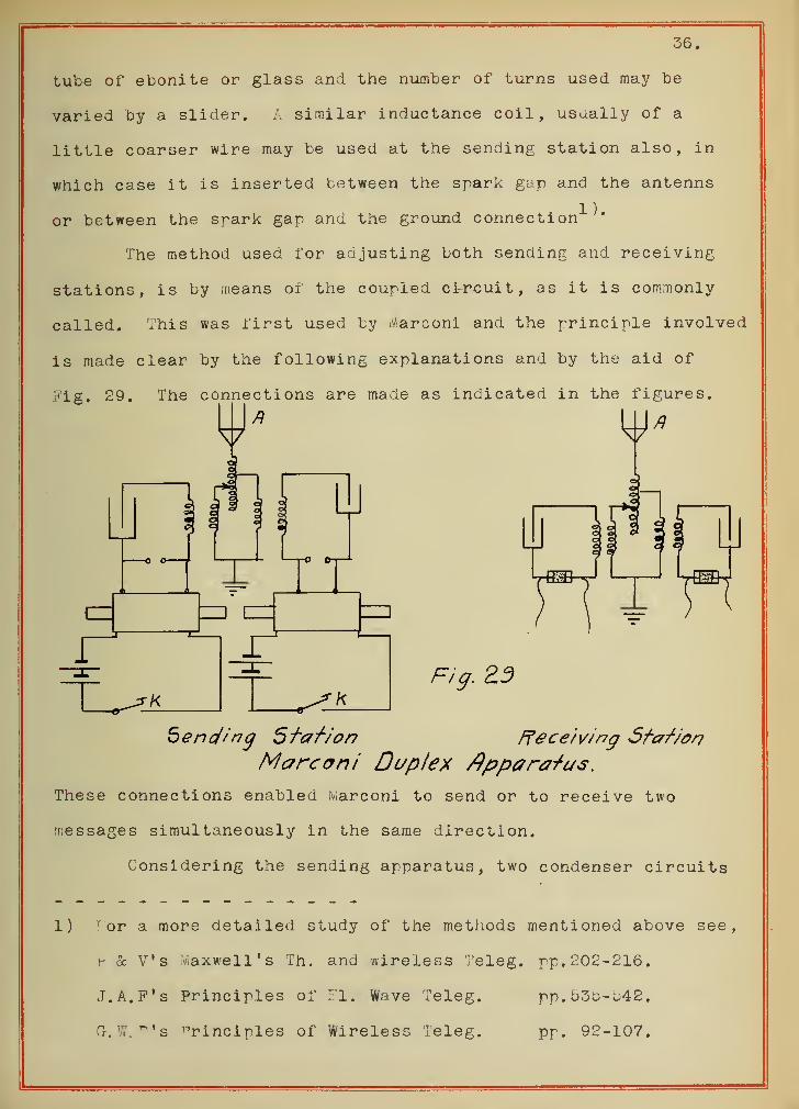
tube of ebonite or glass and the number of turns used may be
varied by a slider. A similar inductance coil, usually of a
little coarser wire may be used at the sending station also, in
which case it is inserted between the spark gap and the antenns
or between the spark gap and the ground connection1 '*
The method used for adjusting both sending and receiving
stations, is by means of the coupled circuit, as it is commonly
called. .his was first used by Marconi and the principle involved
is made clear by the following explanations and by the aid of
Fig. 29. The connections are made as indicated in the figures.
Fig ZD
bend'ng Sfafion ffece'/ving 5fcnf-/on
Marconi Duplex Apparatus.
These connections enabled Marconi to send or to receive two
messages simultaneously in the same direction.
Considering the sending apparatus, two condenser circuits
1) i or a more detailed study of the methods mentioned above see,
r & V's Maxwell's Th. and wireless Teleg. pp. 202-216.
J.A.P's Principles of El, Wave Teleg. pp. 530-542.
a.W.^'s nrincinles of Wireless Teleg. pp. 92-107.
37.
having diiferent values of capacity and self -inductance were in-
dependently charged, and discharged with different periods of
oscillation. ^his duplex wireless telegraphy can be carried on
only when the wave lengths or frequencies of the two sending ap-
paratus are commensurate.
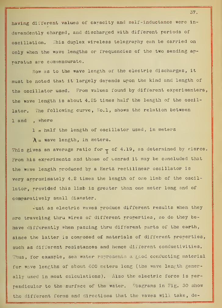
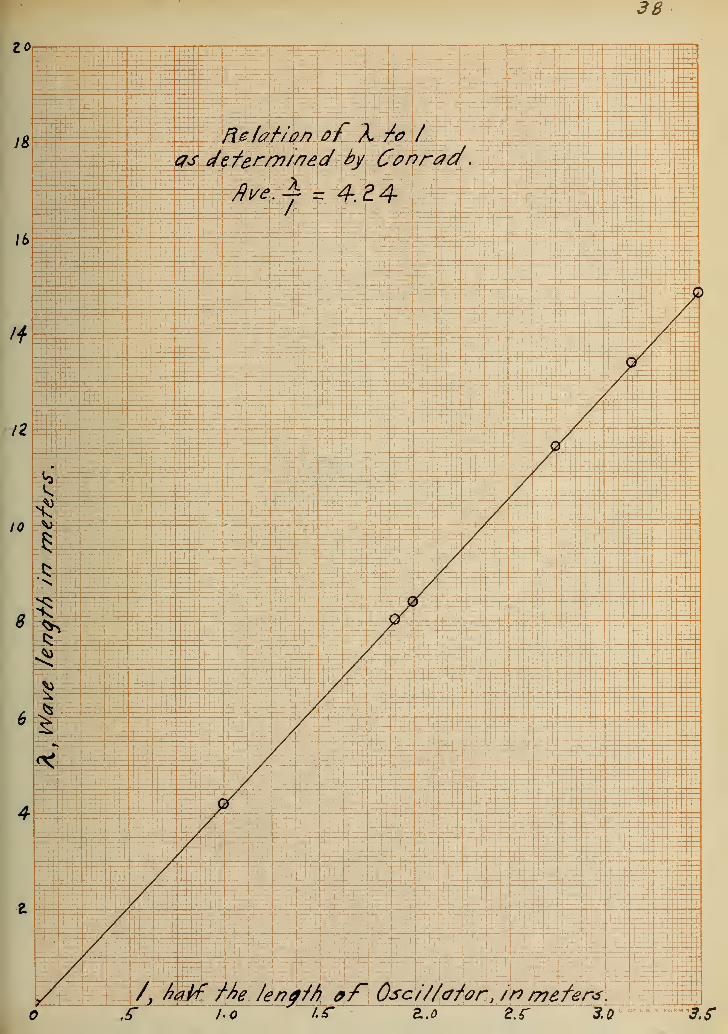
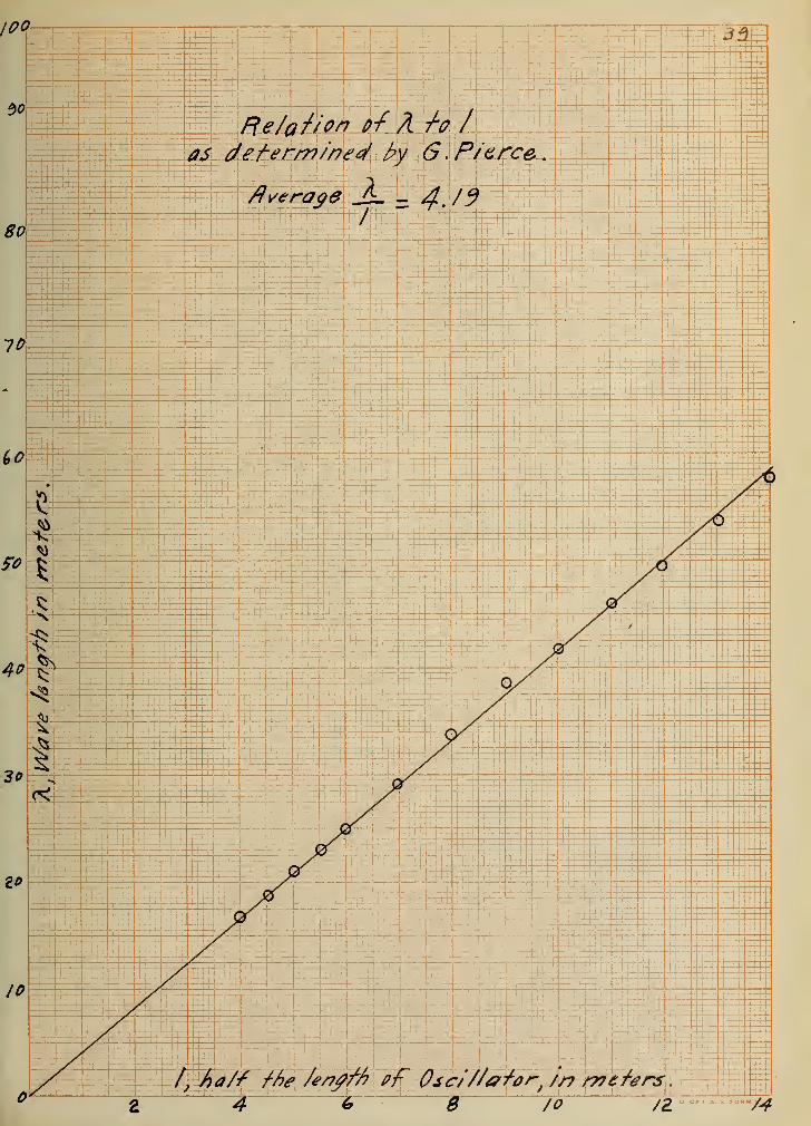
ow as to the wave length of the electric discharges, it
must be noted that it largely depends upon the kind and length of
the oscillator used. From values found by different experimenters,
the wave length is about 4.25 times half the length of the oscil-
lator. The following curve, Ro.l, shows the relation between
1 and , where
1 = half the length of oscillator used, in meters
TV = wave length, in meters.
This gives an average ratio for -j of 4.19, as determined by rierce.
From his experiments and those of oonrad it may be concluded that
the wave length produced by a Hertz rectilinear oscillator is
very approximately 4.2 times the length of one limb of the oscil-
lator, provided this limb is greater than one meter long and of
comparatively small diameter.
-ust as electric waves produce different results when they
are traveling thru wires of different properties, so do they be-
have differently when passing thru different parts of the earth,
since the latter is composed of materials of different properties,
such as different resistances and hence different conductivities.
Thus, for example, sea water represents a gcod conducting material
for wave lengths of about 600 meters long (the wave length gener-
ally used in most calculations). Also the electric force is per-
pendicular to the surface of the water. Oiagrams in Fig. 30 show
the different forms and directions that the waves will take, de-
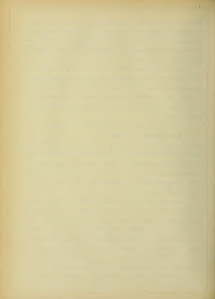
31a
Very Dry ftock
Fig. 30. Forms and Directions pf WavesThru Different Maferia/s .
38
40.
pending upon the medium thru which they are traveling1 ^.
The following curve sheet, p. 41, represents a graphical
form of comparison of transmission distances, data having been
taken from the experiments of Zenneck and ^ierce.
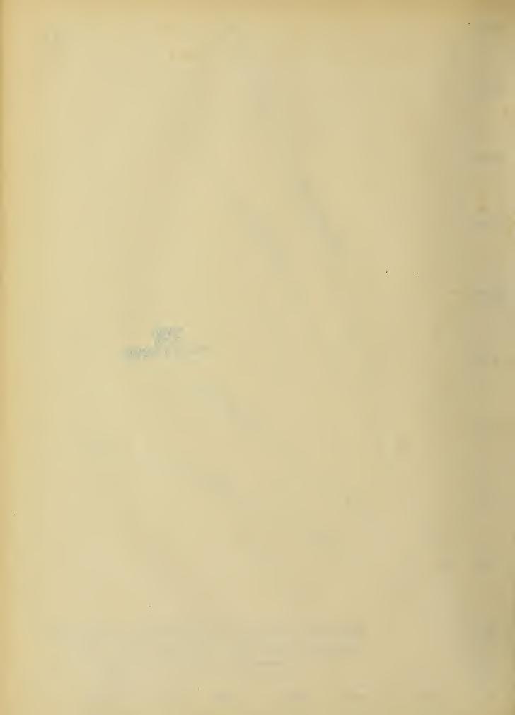
Having shown the effects of different regions of the earth
uron transmission of electric waves, the effect of light or dark-
ness on it should also be noticed. This phenomenon plays an im-
portant part in wireless telegraphy, particularly in distant
transmissions. Thus, for example, apparatus which can send wire-
less messages a certain distance at night, may be able to transmit
only about 44^ of the distance during day, as seen from the ex-
periments of Marconi and G.W. Pickard. The curve on page 42 is
plotted from data given by Pickard and shows the intensity of
transmission of waves during different hours of the day. This
difference is explained as follows: The atmosphere between the
two stations is more conductive in the daytime and hence absorbs
more of the energy of the wave than at night; also, for the same
rower, the leakage by day from the antenna is more and hence the
decrease in the potential results in less oscillatory currents.
To obtain maximum strength of the signals, the different
parts of the sending and receiving circuits must be brought to
resonance as snown at the beginning of this work. This also
largely eliminates the interference resulting from simultaneous
operation of several stations of different frequencies. The main
elements of variation in attuning circuits one to another are
inductance capacity and somewhat resistance. (See Lodge's res-
onant circuit, already discussed) This gives an explanation of
resonance in the simplest circuits. In actual wireless tele-
1) See Zenneck.
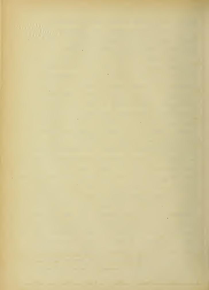
Drd/pafe : Bquiya/rnf d/sfance. over var/ous
terresir/a/mafer/a/s Jn k//orr?efer
See2
ir:-:t~~-:r
O i" i - 5 . S . FORM :
Q| I
KS
ffe/afii/e. /'nftns/Jy received s/g/ia/s. an
-Fr
U- OF I. S. S. FORM !»
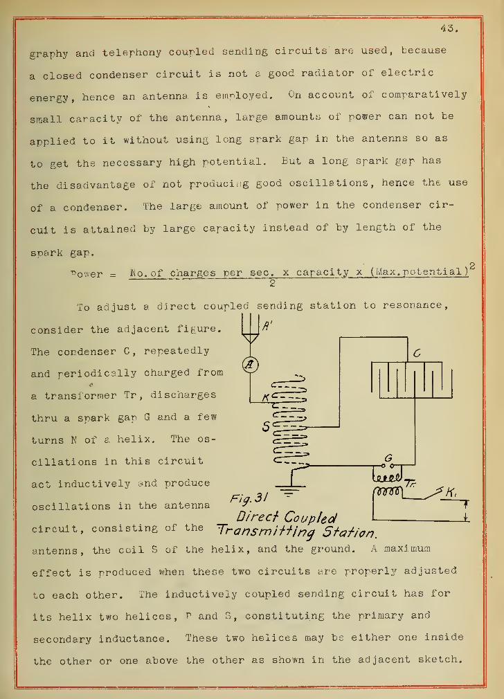
43.
graphy and telephony coupled sending circuits are used, because
a closed condenser circuit is not a good radiator of electric
energy, hence an antenna is employed. On account of comparatively
small capacity of the antenna, large amounts or power can not be
applied to it without using long spark gap in the antenns so as
to get the necessary high potential. But a long spark gap has
the disadvantage of not producing good oscillations, hence the use
of a condenser. The large amount of power in the condenser cir-
cuit is attained by large capacity instead of by length of the
spark gap.
Power = No. of charges per sec , x capaci ty x (Max. potential
)
g
To adjust a direct coupled sending station to resonance,
consider the adjacent figure.
The condenser C, repeatedly
and periodically charged from
a transformer Tr ,discharges
thru a spark gap G and a few
turns N of a helix. The os-
cillations in this circuit
act inductively and produce
oscillations in the antennaFig. 31
Direct Coupledcircuit, consisting of the Transmitting Station.
antenns, the coil S of the helix, and the ground. A maximum
effect is produced when these two circuits are properly adjusted
to each other. The inductively coupled sending circuit has for
its helix two helices, p and 3, constituting the primary and
secondary inductance. These two helices may be either one inside
the other or one above the other as shown in the adjacent sketch.
0.
44.
o o-
'
C
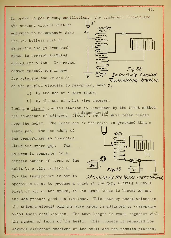
In order to get strong oscillations, the condenser circuit and
I*'the antenna circuit must be \-A
yf Sdcenaanf
adjusted to resonance.** Also
the two helices must be
separated enough from each
other to prevent sparking
during operation. Two rather
common methods are in use
for attuning the Pr and Sc
of the coupled circuits to resonance, namely,
1) By the use of a wave meter,
FigM==" P
He7;7y Inactively Coup/ecf
Transmitting Staf/0/? .
2) By the use of a hot wire ammeter.
Tuning a direct coupled station to resonance by the first method,
isd.iscQii2icct*G(ithe condenser of adjacent figure ^, and the wave meter pieced
near the helix. The lower end of the helix is grounded thru a
srark gap. The secondary of
the transformer is connected
about the spark gap. The
antenna is connected to a
certain number of turns of the
helix by a clip contact K.
Now the transformer is set in
Wm.
operation so as to produce a spark at the gap, blowing a small
blast of air on the spark, if the spark ter:ds to become an arc
and not produce good oscillations. This sets up oscillations in
the antenna circuit and the wave meter is adjusted to (resonance
with) these oscillations. The wave length is read, together with
the number of turns of the helix. This process is repeated for
several different sections of the helix and the results plotted,
45.
turns of helix. as abscissas and wave lengths in meters as ord-
inates. A similar operation is performed with the condenser cir-
cuit, having the antenna and the ground disconnected. Results
are plotted on the same chart and to the same scale. The former
curve is generally known as the "Antenna Circuit" and the latter,
"The Condenser Circuit". From these two curves, for any wave
length we can select the number of turns necessary for the antenna
circuit and for the condenser circuit, in order to bring the two
circuits into resonance.
For adjusting a direct coupled sending station by the hot
wire ammeter, the latter is put in the antenna circuit. The os-
cillations passing thru the fine wire in the ammeter produces
heat, thus causing the wire to expand, which in its expansive
movement acts u^on a pointer passing over a dial, indicating the
current passing thru the sensitive wire. Altho the instrument may
be calibrated in amperes, it is not essential, since the maximum
deflection of the pointer indicates maximum current in the antenna,
which shows that the antenna and condenser circuits are in reson-
ance. To tune up a station, the transformer (see Fig. 31) is set in
action and reading of ammeter taken. Now keeping the apark gap
constant, and leaving the antenna clip k unchanged, the clip k'
of the condenser circuit is moved to a different number of turns
of the helix, and again the current read. This process is repeated
several times to give points for a smooth curve, using turns of
helix as abscissas. From this curve the number of turns corres-
ponding to maximum current may be found.
The wave meter method of attuning the circuits is to be
preferred, because it gives the actual wave lengths that are nec-
essary, if it is desired to set several stations to a particular
predetermined wave length.
46.
The tuning of inductively coupled circuits is about the
same as that described for the direct coupled transmitter.
hen the condenser circuit and the antenna circuit are ad-
justed to resonance, the energy is radiated in waves of two dif-
ferent wave lengths, but only one of these is useful, and the other
one is very easily suppressed. There is a possibility of a third
wave length also, in the case of a tuned transmitter. This is
due to the fact that after a certain number of oscillations the
current in the condenser circuit becomes so small that the flow
of sparks in this circuit ceases. This opens the primary circuit,
and we no longer have a coupled system; so that the secondary
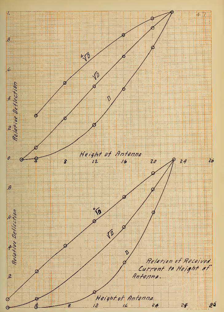
goes on oscillating at its independent frequency. Relation of
current received to height of receiving antenna varies with the
methods of tuning. This relation for the two different methods
of tuning is shown by the graphs on page 47 as experimented by
G. W. 'Pierce. Prom results obtained from these curves it may be
concluded that:
1. The effective current in a vertical receiving antenna,
is proportional to the height of antenna, when this antenna is
brought to resonance with incident waves by an appropriate in-
ductance in series with the antenna.
2. The current in the inductive part of the circuit (the
instrument) shunted with a capacity is proportional to the square
of the height of the vertical receiving antenna, when the circuit
is brought to resonance by appropriate adjustment of the shunt
capacity. .hese laws are only approximate.
It often is the case, that an antenna of not the proper
size causes little current to be received, and gives very dull
resonance. To remedy this, it is best to tune the antenna circuit
48.
as well as the side condenser. This may be accomplished by several
rre thods :
1) Having a variable primary of the receiving transformer.
2) Having a variable inductance in series with the primary.
3) Having a variable condenser shunted around the primary.
4) Having a variable condenser in series with the primary.
;vle thods (1) to (3) inclusive -permit an increase of the wave
length in the antenna and adapt it to longer waves. Method (4)
permits a decrease of the wave length of the antenna and adapts
it to shorter waves. A very desirable arrangement is to have all
these variables combined in one apparatus , so as to be able to
adjust any desirable part for best results.
1) If a wave length arriving at an inductively coupled
receiving station = /I
2) The antenna circuit is adjusted to give wave lengths Aa
3) The condenser circuit is adjusted to wave length = /\c
then theoretically (good for all practical purposes) we have
(1 _ _ 1) = I2
X F% T XT
in which T is tne coefficient of coupling at the receiving station.
It has been found that diminution of the coefficient of
coupling increases the sharpmess of resonance. A far greater in-
fluence has the resistance of detectors upon this. ''-hen a high
resistance is worked in a simple circuit containing an inductance
and capacity renders the resonance dull.
49.
VIII .
ANTENNAE.
From what has been heretofore said, it is evident that the
antenna used in wireless telegraphy is just as important a factor
in successful operation as perhaps any other part of the appara-
tus. The shape, height, quality of material, etc., all enter
into transmitting or receiving electric waves and therefore it is
necessary to give a brief discussion of them.
There have been several types of antennae used, each having
its advantages and disadvantages. Some of the simpler types are:
1) Straight.
2) Flat-top.
3) Fan- shaped.
4) Umbrella.
5) Helical.
6) Zigzag or broken.
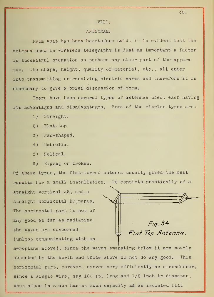
Of these types, the flat-topped antenna usually gives the best
results for a small installation. it consists practically of a
straight vertical aB, and a
Fig. 34*
M Flat Top Antenna
straight horizontal BC , parts.
The horizontal part is not of
any good as far as radiating
the waves are concerned
(unless communicating with an
aeroplane above), since the waves emanating below it are mostly
absorbed by the earth and those above do not do any good. This
horizontal part, however, serves very efficiently as a condenser,
since a single wire, say 100 ft. long and 1/8 inch in diameter,
when alcne in srace has as much capacity as an isolated flat
50.
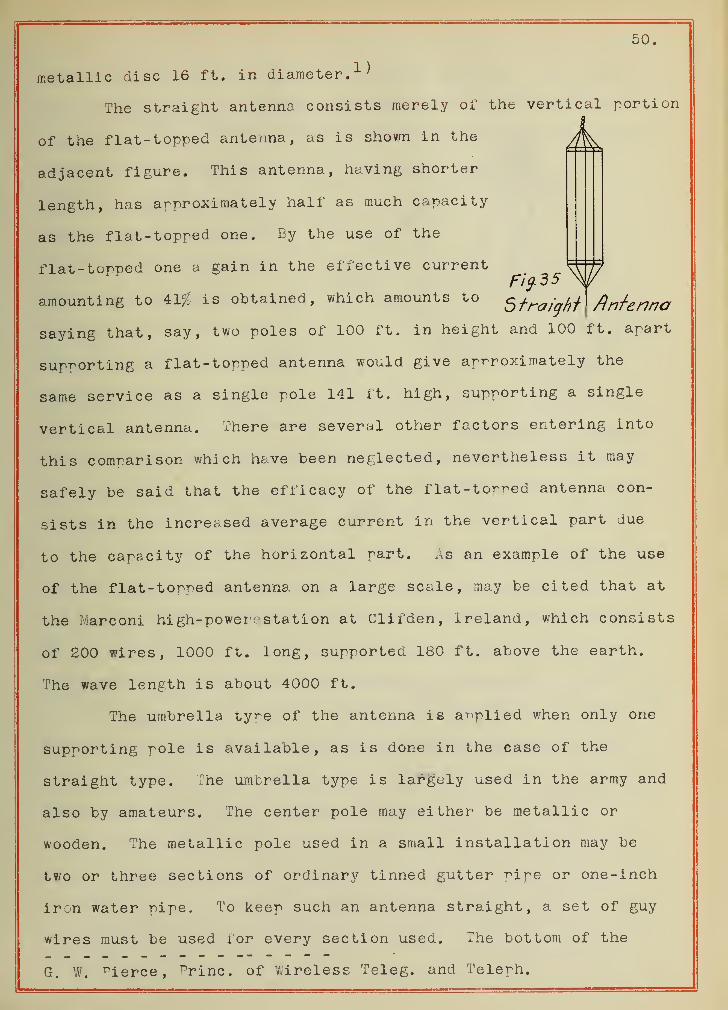
1)metallic disc 16 ft. in diameter.
The straight antenna consists merely of the vertical portion
of the flat- topped antenna, as is shown in the
adjacent figure. This antenna, having shorter
length, has approximately half as much capacity
as the flat- topped one. By the use of the
flat-topped one a gain in the effective current_ VJ/7
amounting to 41$ is obtained, which amounts to §fraf*jrf Antenna
saying that, say, two poles of 100 ft. in height and 100 ft. apart
supporting a flat-topped antenna would give approximately the
same service as a single pole 141 ft. high, supporting a single
vertical antenna. There are several other factors entering into
this comparison which have beer neglected, nevertheless it may
safely be said that the efficacy of the flat-torr^ed antenna con-
sists in the increased average current in the vertical part due
to the capacity of the horizontal part. As an example of the use
of the flat-topped antenna on a large scale, may be cited that at
the Marconi high-power, station at Clifden, Ireland, which consists
of 200 wires, 1000 ft. long, supported 180 ft. above the earth.
The wave length is about 4000 ft.
The umbrella tyre of the antenna is applied when only one
supporting pole is available, as is done in the ease of the
straight type. The umbrella type is largely used in the army and
also by amateurs. The center pole may either be metallic or
wooden. The metallic pole used in a small installation may be
two or three sections of ordinary tinned gutter pipe or one-inch
iron water pipe. To keep such an antenna straight, a set of guy
wires must be used lor every section used. The bottom of the
G. W. ^ierce, princ. of Wireless Teleg. and Telerh.

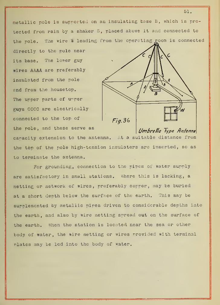
51.
metallic pole is supported on an insulating base B, which is pro-
tected from rain by a. shaker S, placed above it and connected to
the pole. The wire w leading from the operating room is connected
directly to the pole near
its base. The lower guy
wires AAAA are preferably
insulated from the pole
and from the housetop.
The urper parts of upper
guys CCCC are electrically
connected to the top of
the role, and these serve asUmbrella type flnfenno
capacity extension to the antenna. At a suitable distance from
the top of the pole high-tension insulaters are inserted, so as
to terminate the antenna.
For grounding, connection to the pipes of water suprly
are satisfactory in small stations. where this is lacking, a
netting or network of wires, preferably copper, may be buried
at a short depth below the surface of the earth. This may be
supplemented by metallic pipes driven to considerable depths into
the earth, and also by wire netting spread out on the surface of
the earth. when the station is located near the sea or ottter
body of water, the wire netting or wires provided with terminal
rlates may be led into the body of water.
52.
IX.
WIRELESS TELEPHOHY.
Radiotelephony, or wireless telephony as it is commonly
called, consists in transmission of articulate speech over long
distances without wires. Electromagnetic waves briefly discussed
previously are made use of in this connection. The success in
wireless telephony consists in a transmitter, which can produce
unchanged electric radiation and in a receiver which should be
quantitative in action, that is one not merely set in operation
by oscillations like a coherer, but producing effects proportional
to the amplitudes of the incident waves.
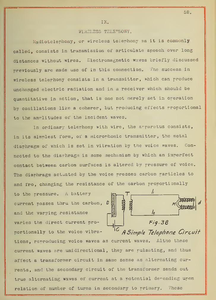
In ordinary telephony with wire, the apparatus consists,
in its simplest form, of a microphonic transmitter, the metal
diaphragm of which is set in vibration by the voice waves. Con-
nected to the diaphragm is some mechanism by which an imperfect
contact between carbon surfaces is altered by pressure of voice.
The diaphragm actuated by the voice presses carbon particles to
and fro, changing the resistance of the carbon proportionally
to the pressure. A battery u-i T, I .
current passes thru the carbon, D % g'§j
m(C I d111 .
and the varying resistancef [
/2
varies the direct current pro- F/j.38
portionaiiy to the voice vibra- ~ A Simple Telephone Circuii-
tions, reproducing voice waves as current waves. Altho these
current waves are unidirectional, they are pulsating, and thus
affect a transformer circuit in same sense as alternating cur-
rents, and the secondary circuit of the transformer sends out
true alternating waves of current at a potential defending upon
relation of number of turns in secondary to primary. These
53.
alternating waves when acting upon the magnetic circuit of the
telephone receiver at the distant end make its diaphragm vibrate
so precisely in imitation of the original voice vibrations as to
reproduce successfully spoken words. The loss of power is con-
siderable, but the wave form is preserved almost perfectly, even
over very long lines, such as that from New York to San Francisco,
recently opened with impressive ceremony.
In wireless telephony, the wires 1-^ and 12 are removed
and unchanged electromagnetic waves employed instead. In brief,
in wireless telephony, we need:
(a) An arrangement for generating the undamaged electric
waves in the transmitter.
(b) Means for modulating the amplitude of these waves
in accordance with the wave form of artificial speech.
(c) An arrangement for receiving these electric waves of
variable amplitude, and causing them to affect a speaking telephone.
To produce the persistent train of waves of high frequency
necessary, several methods are used, such as:
1) The singing arc method (see p /9 )
2) The mercury arc method.
3) The high frequency alternator method, etc.
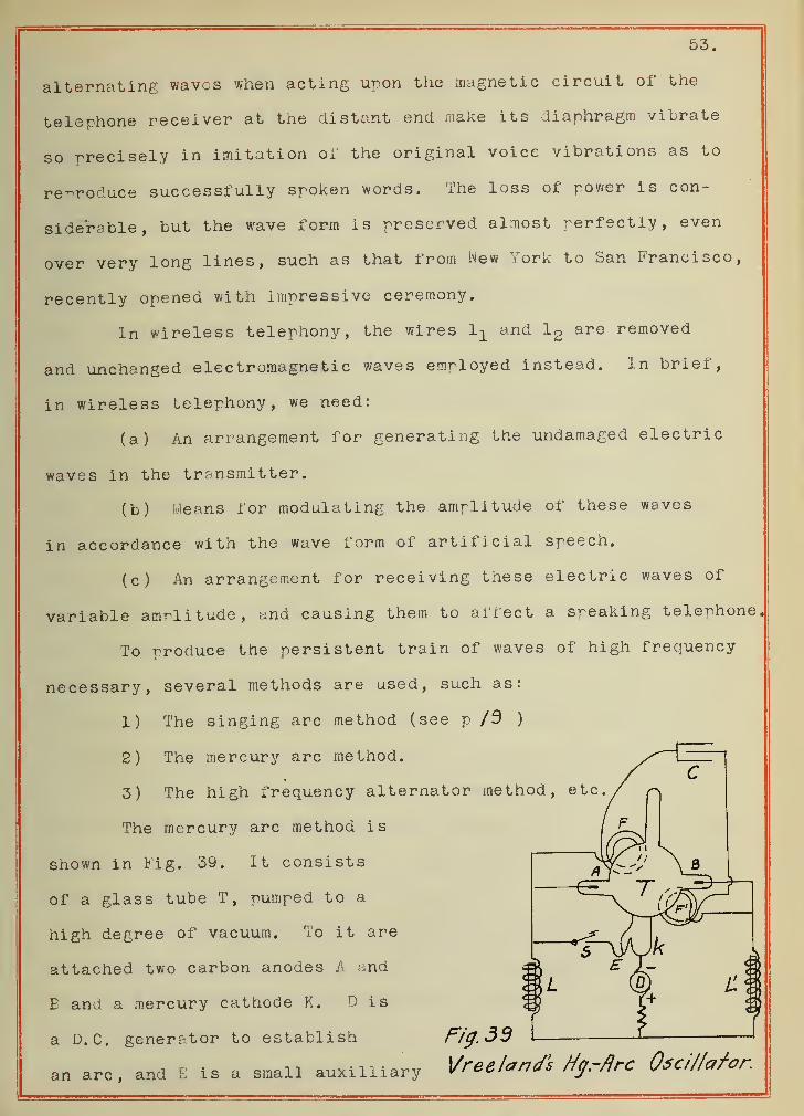
The mercury arc method is
shown in Fig. 39. It consists
of a glass tube T, pumped to a
high degree of vacuum. To it are
attached two carbon anodes A and
E and a mercury cathode K. D is
a D.C. generator to establish
an arc, and E is a small auxilliary
Fig.dd
Vree land's tig.-fire Oscillator.
54.
electrode to help stare this arc in the chamber. '/.'hen this arc
is established, it will be seen to divide into two branches--
one between A and K, the other between B and K. The resistance
R and the choke coils L and are used to steady the two arcs,
between the two anodes A and B is connected an oscillation cir-
cuit, containing a condenser U and two coils FP^ , the function
of the latter by their magnetomotive force being to deflect the
arc inside the vacuum bulb, and to cause the cathode stream of
this arc to oscillate in a plane perpendicular to the axis of the
coils in such a manner that this oscillating cathode stream im-
pinges first on one and then on the other of the anodes A and B.
This deflection of the cathode beam is produced due to the fact
that the two parts can not keep equal conductivities alter the
arc has been established, and this causes irregular fluctuations
which in turn give rise to oscillations, after which they give
place to periodic fluctuations controlled by the alternating field.
Now when the condenser C is charged to a certain point, it dis-
charges, reversing trie field, and causing the arc to be deflected
in the other direction, so as to force the current thru the os-
cillating circuit from A to B, This process is repeated indef-
initely, which amounts to feeding the energy into the oscillating
circuit in synchronism with the oscillations, which are thus main-
tained at constant amplitude and at a frequency determined by the
self-inductance and capacity of the circuit.
The circuits in wireless telephony are very much like those
in wireless telegraphy. In the former, the transmitting apparatus
sends out a persistant train of electric waves of high frequency.
These waves are varied b;y the voice thru the telephone transmitter,
and so moulded that relatively low frequency voice-reproducing

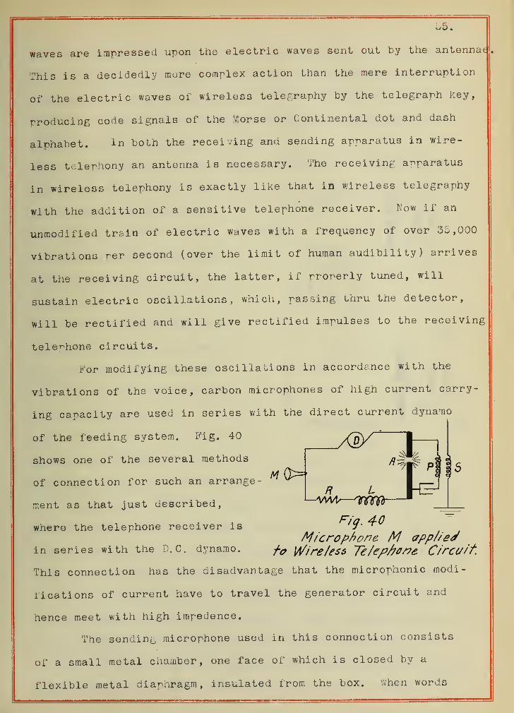
waves are impressed upon the electric waves sent out by the antennae
This is a decidedly more complex action than the mere interruption
of the electric waves of wireless telegraphy by the telegraph key,
producing code signals of the Morse or Continental dot and dash
alphabet. in both the receiving and sending apparatus in wire-
less telephony an antenna is necessary. The receiving apparatus
in wireless telephony is exactly like that in wireless telegraphy
with the addition of a sensitive telephone receiver. Now if an
unmodified trsin of electric waves with a frequency of over 35,000
vibrations rer second (over the limit of human audibility) arrives
at the receiving circuit, the latter, if properly tuned, will
sustain electric oscillations, which, passing thru the detector,
will be rectified and will give rectified impulses to the receiving
telephone circuits.
For modifying these oscillations in accordance with the
vibrations of the voice, carbon microphones of high current carry-
ing capacity are used in series with the direct current dynamo
of the feeding system. Fig. 40 /^/^ |~
shows one of the several methods
of connection for such an arrange- ^R L
ment as that just described, VWV TWtfr
where the telephone receiver is l§' ^0Microphone M applied
in series with the D.C. dynamo. Wire/ess 7e/ep/70/?e C/rcc//f.
This connection has the disadvantage that the microphonic modi-
iications of current have to travel the generator circuit and
hence meet with high impedence.
The sending microphone used in this connection consists
of a small metal chamber, one face of which is closed by a
flexible metal diaphragm, insulated from the box. /.hen words
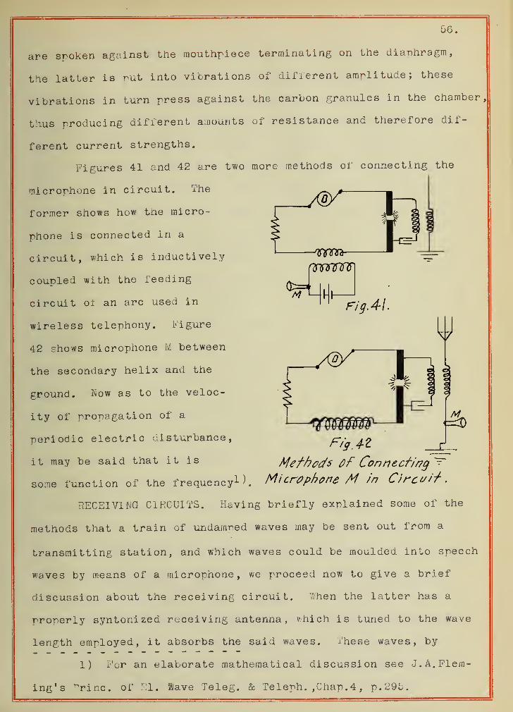
anmnnr
M MM-Fig. 4-1
56.
are spoken against the mouthpiece terminating on the diaphragm,
the latter is put into vibrations of different amplitude; these
vibrations in turn press against the carbon granules in the chamber,
thus producing different amounts of resistance and therefore dif-
ferent current strengths.
Figures 41 and 42 are two more methods of connecting the
microphone in circuit. The
former shows how the micro-
phone is connected in a
circuit, which is inductively
coupled with the feeding
circuit oi an arc used in
wireless telephony. Figure
42 shows microphone M between
the secondary helix and the
ground. Kow as to the veloc-
ity of propagation of a
periodic electric disturbance,
it may be said that it is Mefhods Of Connecting
some function of the frequency1 ). Microphone M in Circuit.
RECEIVING CIRCUITS. Having briefly explained some of the
methods that a train of undamped waves may be sent out from a
transmitting station, and which waves could be moulded into speech
waves by means of a microphone, we proceed now to give a brief
discussion about the receiving circuit. ::.hen the latter has a
properly syntonized receiving antenna, which is tuned to the wave
length employed, it absorbs the said waves. These waves, by
1) For an elaborate mathematical discussion see J.A.Flem-
ing's "rinc. of El. Save Teleg. & Teleph. ,Chap. 4 , p. 29b.
Fig. 4-Z
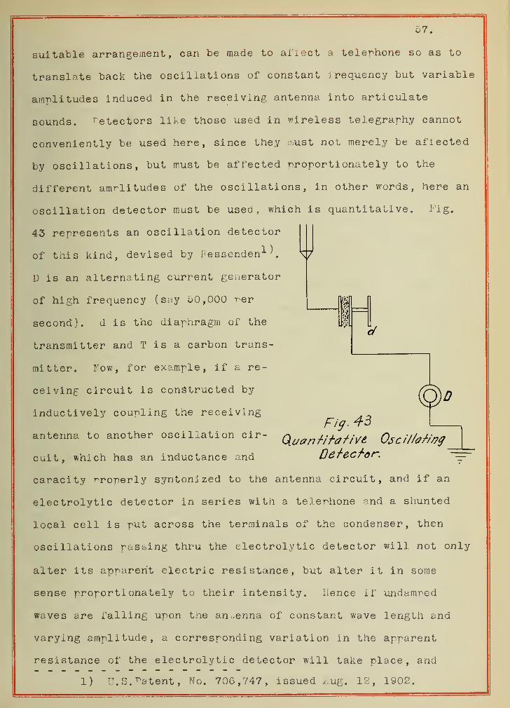
57.
suitable arrangement, can be made to affect a telephone so as to
translate back the oscillations of constant irequency but variable
amplitudes induced in the receiving antenna into articulate
sounds. r etectors like those used in wireless telegraphy cannot
conveniently be used here, since they i.ust not merely be affected
by oscillations, but must be affected proportionately to the
different amplitudes of the oscillations, in other words, here an
oscillation detector must be used, which is quantitative. Fig.
43 represents an oscillation detector
of this kind, devised by Pessenden1 ^.
D is an alternating current generator
of high frequency ( say 50,000 r-er
second). J is the diaphragm of the
transmitter and T is a carbon trans-
mitter. Fow, for example, if a re-
ceiving circuit is constructed by
inductively coupling the receivingFig- 43
antenna to another oscillation cir- QLuanHf.atjVe QscUbHtycult, which has an inductance and Detector.
capacity properly syntonized to the antenna circuit, and if an
electrolytic detector in series with a telephone and a shunted
local cell is put across the terminals of the condenser, then
oscillations pasting thru the electrolytic detector will not only
alter its apparent electric resistance, but alter it in some
sense proportionately to their intensity. Hence if undamped
waves are falling upon the antenna of constant wave length and
varying amplitude, a corresponding variation in the apparent
resistance of the electrolytic detector will take place, and
1) U.S. Patent, No. 706,747, issued Aug. 12, 1902.
58.
therefore a corresponding variation in the currents thru the tele-
phone. It is evident, then, that the telephone diaphragm will
emit a sound which will correspond with the fluctuation in the
am-litude of the incident waves, and it will, therefore, repro-
duce speech made against the diaphragm of the transmitting micro-
rhone. '"here have been various oscillation detectors devised,
each of which has its particular advantages and disadvantages.
Among those most common in this country are Fessenden's electro-
lytic detector, J. A. Fleming's glow-lamp or ionized gas-detector,
the thermo-electric detectors, ^ierce's crystal detectors, etc.
It is of interest to know that rather successful wireless
telephonic communications have been obtained, by various experi-
menters, for distances even as much as 600 miles, both in the
United States and Europe. For example, -rofessor Fessenden was
able to get results mentioned by a high frequency alternator
(75,000 cycles rer second, well above t.ie limit of audibility)
of 2.5 K.W. output, at 22o volts, which when connected to an
antenna (in resonance with it) either directly or inductively,
a wave length of ^XQqq
- = 4000 meters, (suitable for wireless
telephony) was obtained. Heights of antennae used were 440 ft.
and 200 ft. at the two stations.
The high frequency generator is too expensive and the arc
method too uncertain to afford a thoroughly satisfactory basis
for operating commercial radi oteiegraphy at the present time, and
efforts should be made to be able to produce persistent oscil-
lations in a simpler and easier way.
X
CONCLUSIONS.
In conclusion, it may be said that in setting up a wireless
set, in addition to what has been thus far riven, the following-
suggestions will also be found helpful to the experimenter.
The condensers used in the sending apparatus of an induct-
ively courled or direct coupled tyre, must be made strong enough
electrically to permit the storage of large quantities of elec-
tricity used in producing waves. The bank of Leyden jars or of
flat glass plates provided with metallic coatings are very con-
venient. If brush discharges occur in case the flat plate con-
densers are used, the latter may be submerged in castor oil to
prevent any undesirable discharge. In Marconi's high-power
stations at Clifden, Polden and Wellfleet, air condensers, formed
of metallic plates with air Letween as dielectric, are being used
very successfully.
As to the capacity used in a given coupled type sending
. , , . . . ..„ „ 1000 x p
station, it may be lound by the relation C= -p^ ,
in which C = capacity of condenser in farads,
P = power in K.W. supplied to condenser by a transformer,
f s number of cycles of an A.C. source,
V = -potential across the condenser at one discharge.
.hen using the above formula for capacity, 15,000 volts to the
centimeter length of a^ark may be used, since this is about the
value of the potential when the spark gap is heated and ionized
by continuous sending.
Now as to the transformer, it must be designed to be in
resonance with the condenser. This is rather troublesome. The
transformer for this purpose has for its load a condenser which
60.
will attain a maximum charge for a certain resonant relation of
the constants of the transformer to the capacity of the condenser.'
hen a spark forms it is soon extinguished, while the ordinary
lighting transformer is designed to supply more and more power
as the load is made of lower and lower resistance and when a spark
forms it becomes an arc and does not extinguish. This is not, of
course, desirable. if, however, a common closed core transformer
is used, the desired result may be obtained with a proper adjust-
able resistance placed in the primary circuit of the transformer.
The same result can be more economically obtained by the use of
an adjustable coreless inductance in series with the primary.
It can also be attained by an adjustable inductance in series with
the secondary of the closed-core transformer. With an open-core
type of transformer and an adjustable inductance in the primary
circuit, considerably greater flexibility in attaining resonance
with condensers of different capacities is possible, and it is
often preferred by many to use the open-core transformer.
With power not exceeding 5 kw. and a voltage not higher
than 150 volts, the primary circuit can be interrupted with an
ordinary Morse telegraph key provided with heavy platinum or
silver contacts. For larger values of the power, some form of
relay key by which the current is broken between large contacts
under oil is generally employed. The adjacent diagram shows the
connections for a complete station, the sending apparatus being
shown at the right and the receiving apparatus at the left and
a cut-over switch for throwing from sending to receiving is shown
near the center. This switch usually has three blades, mounted
on a hard rubber axle, and sufficiently far apart to avoid spark-
ing between the blades of the switch or from the sending to the
s4
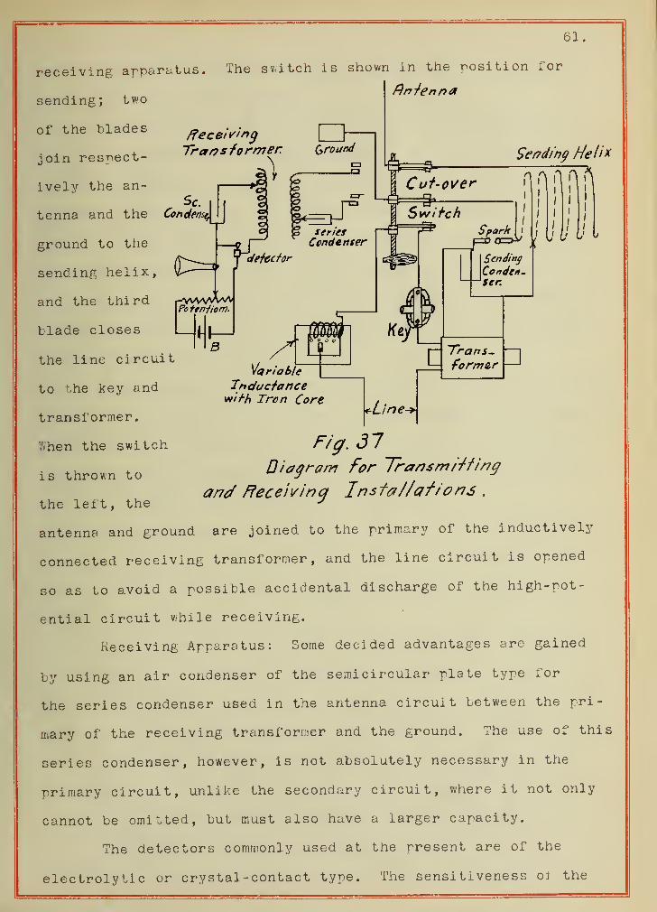
61.
Receiving
Sending Helix
receiving apparatus. The switch is shown in the position for
Antennasending; two
of the blades
join respect-
ively the an-
tenna and the
ground to the
sending helix,
and the third ^wvaAaa-Po feniiom.
blade closes
the line circuit
to the key and
transformer,
i hen the switch
is thrown to
the left, the
Variable
Inductancewirh Tron Core
Fig, 37Diagram for Transmitting
and Receiving 1nstat/crfions .
antenna and ground are joined to the primary of the inductively
connected receiving transformer, and the line circuit is opened
so as to avoid a possible accidental discharge of the high-pot-
ential circuit while receiving.
Receiving Apparatus: Some decided advantages are gained
by using an air condenser of the semicircular plate type for
the series condenser used in the antenna circuit between the pri-
mary of the receiving transformer and the ground. The use of this
series condenser, however, is not absolutely necessary in the
primary circuit, unlike the secondary circuit, where it not only
cannot be omitted, but must also have a larger capacity.
The detectors commonly used at the present are of the
electrolytic or crystal-contact type. The sensitiveness oi the
62.
detector and its readiness to detect signals may be tested by a
buzzer device for that purpose.
vhile various forms of wireless apparatus are being con-
stantly developed and their use increased, it is my belief that
the use of wireless telegraphy and particularly of wireless tele-
phony is, after all, not unlimited. Thus, for example, it hardly
seems to be possible, that people may some day replace the thou-
sands of telephones in a city (not to speak of larger spaces) by
wireless apparatus, on account of the impossibility of obtaining
the enormous number of different frequencies for preventing each
of them from interfering with others.
In conclusion it might be said, that this and other similar
limitations in the use of wireless communications is not, however,
a reason why should not the workers in the field do their best
to develop this science further, for there is much to be done in
the field before these limitations are reached.


4.