a study on bio-insect and arti cial robot interaction · a study on bio-insect and arti cial robot...
TRANSCRIPT

Thesis for Master’s Degree
A Study on Bio-insect and Artificial Robot
Interaction
Ji-Hwan Son
School of Information and Mechatronics
Gwangju Institute of Science and Technology
2010

석사학위논문
바이오 곤충과 로봇의 상호작용에 관한 연구
손 지환
정 보 기 전 공 학 부
광 주 과 학 기 술 원
2010

A Study on Bio-insect and Artificial RobotInteraction
Advisor: Hyo-Sung Ahn
by
Ji-Hwan Son
School of Information and Mechatronics
Gwangju Institute of Science and Technology
A thesis submitted to the faculty of the Gwangju Institute of Science
and Technology in partial fulfillment of the requirements for the degree
of Master of Science in the School of Information and Mechatronics
Gwangju, Republic of Korea
Dec 7, 2009
Approved by
Professor Hyo-Sung Ahn
Thesis Advisor

A Study on Bio-insect and Artificial Robot
Interaction
Ji-Hwan Son
Accepted in partial fulfillment of the requirements for the
degree of Master of Science
Dec 7, 2009
Thesis Advisor
Prof. Hyo-Sung Ahn
Committee Member
Prof. Tae-Sun Choi
Committee Member
Prof. Vladimir l. Shin

Dedicated to my family

MS/IM20081135
Ji-Hwan Son. A Study on Bio-insect and Artificial Robot Interaction.School of Information and Mechatronics. 2010. 73p. Advisor: Prof. Hyo-Sung Ahn.
Abstract
This theresis addresses on-going research called BRIDS(Bio-insect and artificial
Robot Interaction based on Distributed Systems) that is a trial to formulate bio-insect
and artificial robot interaction based on reinforcement learning. This thesis is divided
into three major parts.
First, we briefly review relevant research works in this field. Since a cooperation
among mobile agents is a key technology, we examine cooperative reinforcement learn-
ing. Specifically we will briefly review the concept of area of expertise in cooperative
learning area. In fact bio-insect and artificial robot interaction has been studied in
Leurre[1, 2]. Our research, however, has a key difference from Leurre in that it is to
drive bio-insect by coordination of a group of mobile robots towards a desired point.
In author’s best knowledge, driving bio-insect towards a desired point based on fully
autonomous coordination of multiple mobile agents has not been studied in existing
publications. [3]
Second, this thesis introduces advanced framework and simulation results. When we
did experiments using real bio-insects, their movement showed a little randomness. For
this reason, fuzzy logic is employed to drive the model-free bio-insect towards a desired
point. The framework formulated in this thesis is based on fuzzy logic based reward
system and fuzzy logic based expertise measurement system. Fuzzy logic based reward
system uses three inputs and an output resulting in numerical value within -1 to 1.
Fuzzy logic based expertise measurement system is inspired by area of expertise. In area
of expertise method, it uses expertise measurement equation for finding an expert agent.
– i –

Based on area of expertise method, our method uses three expertise measurements
to calculate score of individual agent. Based on this score, agents can share their
intelligences with weighted scores. Simulation results demonstrate the validity of the
framework established in this research.[4]
Finally, one of the most challenging problems of the BRIDS is that a bio-insect
does not usually react to actuation. When we try to stimulate the bio-insect for our
purpose by our hardware system, its reaction is not that straightforward. From various
trials-and-errors, we finally found actuation mechanism for an interaction between the
bio-insect and the artificial robot. This thesis reports what we have done to actuate a
bio-insect and experimental test results with explanation of the hardware platform.[5, 6]
c©2010
Ji-Hwan Son
ALL RIGHTS RESERVED
– ii –

MS/IM20081135
손지환. 바이오 곤충과 로봇의 상호작용에 관한 연구. 정보기전공학부.2010. 73p. 지도교수: 안효성.
국 문 요 약
이 논문은 현재 진행하고 있는 BRIDS(Bio-insect and artificial Robot Interaction
based on Distributed Systems)로명한연구로서강화학습법을기반으로한바이오-곤
충과 로봇간의 상호작용에 대한 논문이다. 이 논문은 크게 세 부분으로 나누어져 있
다. 우선 이 논문에서는 관련 분야들에서 어떤 연구가 진행되고 있는지 알아볼 것이
다. 모바일 로봇관점에서 로봇간에 협력은 하는 것은 핵심 기술이기 때문에 협동 강
화 학습을 통하여 진행해 나갈 것이다. 또한 협동 강화 학습법 중에서 특히 Area of
Expertise에대해서검토할것이다. 곤충과인공로봇간의상호작용은 Leurre [1, 2]에
의해먼저연구되었다. 하지만이연구와 Leurre와다른점은특정형태를이룬모바
일 로봇들이 바이오-곤충을 목표 위치까지 자동적으로 몰고 갈 수 있게 만드는 것이
다. 이러한 연구는 아직까지 연구되거나 논문으로 발표된 사례를 찾지 못했다. [3]
두 번째로 이 논문에서는 앞서 소개한 연구를 위해 설계한 시스템과 그 시뮬레이션
결과에 대해서 설명할 것이다. 바이오-곤충의 반응 성을 테스트 할 때 그 결과는 약
간 무작위성을 보였다. 이러한 이유로 이 연구에서는 바이오-곤충을 목표 지점까지
몰기 위해서 퍼지 로직을 이용한다. 이 시스템은 퍼지 로직 기반의 보상 시스템과
퍼지 로직 기반의 전문성 판별 시스템으로 구성되어 있다. 퍼지 로직 기반의 보상
값 제작 알고리즘은 세 가지의 입력 값을 통하여 설계되어 있는 퍼지 함수들을 통하
여 -1에서 1사이의 보상 값을 출력으로 나타낼 수 있다. Area of Expertise에서 영감
을 얻은 퍼지 로직 기반의 전문성 판별 시스템은 각 에이전트의 능력을 3가지의 능
력값을체크하여각에이전트의결과를점수로나태내며,이점수들을바탕으로서
로 학습한 정보를 교환하는 시스템이다. 시뮬레이션 결과를 통하여 이 시스템의 나
타내었다. [4]마지막으로이연구를진행해나가면서가장어려운문제는바이오-곤
충이 모바일 로봇의 자극에 반응하지 않는 점이었다. 연구를 위하여 구성한 하드웨
– iii –

어 시스템에서 실험을 진행하였을 때, 바이오-곤충은 일반적인 자극들을 가하였을
때 별다른 반응을 보이지 않았으나, 다양한 시도와 실패를 통하여 마침내 바이오-곤
충과 상호작용할 수 있는 방법을 발견하였다. 이 논문에서는 연구를 위해 설치한 하
드웨어 시스템에 대해서 설명할 것이며, 그리고 바이오-곤충과 마이크로 모바일 로
봇간의 상호작용 실험에 대한 설명과 실험 결과에 대해서 다룰 것이다. [5, 6]
c©2010
손 지환
ALL RIGHTS RESERVED
– iv –

Contents
Abstract (English) i
Abstract (Korean) iii
List of Contents v
List of Tables vii
List of Figures viii
1 Introduction 1
1.1 Bio-insect and artificial Robot Interaction based on Distributed Systems
(BRIDS) . . . . . . . . . . . . . . . . . . . . . . . . . . . . . . . . . . . 1
1.2 Motivation and Goal . . . . . . . . . . . . . . . . . . . . . . . . . . . . 2
1.3 Related Works . . . . . . . . . . . . . . . . . . . . . . . . . . . . . . . . 5
1.3.1 Leurre . . . . . . . . . . . . . . . . . . . . . . . . . . . . . . . . 5
1.3.2 Locomotion control of bio-robotic system via electric stimulation 6
1.3.3 Pheromone-guided mobile robots . . . . . . . . . . . . . . . . . 6
1.3.4 Roach Bot . . . . . . . . . . . . . . . . . . . . . . . . . . . . . . 8
1.3.5 Guiding robot’s behaviors using pheromone communication . . . 8
1.3.6 Behavior of cockroach by pheromone source . . . . . . . . . . . 10
1.3.7 Antennal and locomotor responses to attractive and aversive odor
in the searching cockroach . . . . . . . . . . . . . . . . . . . . . 10
1.4 Organization of the thesis . . . . . . . . . . . . . . . . . . . . . . . . . 11
2 Background Material 13
2.1 Introduction . . . . . . . . . . . . . . . . . . . . . . . . . . . . . . . . . 13
2.2 Reinforcement Learning . . . . . . . . . . . . . . . . . . . . . . . . . . 13
2.2.1 Q-learning . . . . . . . . . . . . . . . . . . . . . . . . . . . . . . 13
2.3 Cooperative Reinforcement Learning . . . . . . . . . . . . . . . . . . . 14
2.4 Area of Expertise . . . . . . . . . . . . . . . . . . . . . . . . . . . . . . 20
2.4.1 Area of Expertise . . . . . . . . . . . . . . . . . . . . . . . . . . 20
2.4.2 Expertise Measure . . . . . . . . . . . . . . . . . . . . . . . . . 21
2.4.3 Weight Strategy Sharing . . . . . . . . . . . . . . . . . . . . . . 21
– v –
2.5 Similar Concept in Neural Network Area . . . . . . . . . . . . . . . . . 23
2.6 Fuzzy Logic . . . . . . . . . . . . . . . . . . . . . . . . . . . . . . . . . 24
2.7 Summary . . . . . . . . . . . . . . . . . . . . . . . . . . . . . . . . . . 25
3 Fuzzy Logic based Reward and Expertise Measurement System for
Cooperative Reinforcement Learning 27
3.1 Introduction . . . . . . . . . . . . . . . . . . . . . . . . . . . . . . . . . 27
3.2 Structure of Fuzzy Logic based Reward and Expertise Measurement Sys-
tem for Cooperative Reinforcement Learning . . . . . . . . . . . . . . . 27
3.3 Definition of State and Actions . . . . . . . . . . . . . . . . . . . . . . 28
3.4 Structure of Fuzzy Logic based Reward System . . . . . . . . . . . . . 29
3.5 Structure of Fuzzy Logic based Expertise Measurement System . . . . . 32
3.6 Simulation Results . . . . . . . . . . . . . . . . . . . . . . . . . . . . . 37
3.7 Summary . . . . . . . . . . . . . . . . . . . . . . . . . . . . . . . . . . 41
4 Experimental Platform and Experiments 44
4.1 Introduction . . . . . . . . . . . . . . . . . . . . . . . . . . . . . . . . . 44
4.2 Hardware Platform Setup . . . . . . . . . . . . . . . . . . . . . . . . . 44
4.3 The bio-insect and artificial robot interaction: Experiment . . . . . . . 50
4.3.1 The Model of Bio-insect and Experiments . . . . . . . . . . . . 50
4.3.2 Artificial Robot: An Agent . . . . . . . . . . . . . . . . . . . . . 53
4.3.3 Experiment Setup . . . . . . . . . . . . . . . . . . . . . . . . . . 56
4.3.4 Experiment Results . . . . . . . . . . . . . . . . . . . . . . . . . 57
4.4 Summary . . . . . . . . . . . . . . . . . . . . . . . . . . . . . . . . . . 58
5 Conclusion and Future Work 65
References 67
– vi –

List of Tables
2.1 Various form of expertise measure [7], [8], [9]. . . . . . . . . . . . . . . 26
3.1 Fuzzy Rules for the Fuzzy Logic based Reward System[4]. . . . . . . . . 31
3.2 Fuzzy Rules for Fuzzy Logic Based Expertise Measurement System[4]. . 35
3.3 Algorithm : The Fuzzy Logic Based Reward and Expertise Measurement
System for Cooperative Reinforcement Learning[4]. . . . . . . . . . . . 36
3.4 Average Results of Arrival Iteration for 5 Episodes [4]. . . . . . . . . . 40
3.5 Average Results of Arrival Distance of the Bio-insect’s Trajectory for 5
Episodes [4]. . . . . . . . . . . . . . . . . . . . . . . . . . . . . . . . . . 40
4.1 The Results from our Designed Experiment[6]. . . . . . . . . . . . . . . 58
– vii –

List of Figures
1.1 Our main goal is to drive a bio-insect towards desired goal point using
a group of micro mobile robots. . . . . . . . . . . . . . . . . . . . . . . 3
1.2 Flowchart of proposed community composed of distributed decision, dis-
tributed control and distributed sensing. Subsystems are connected in
a feedback loop manner[3]. . . . . . . . . . . . . . . . . . . . . . . . . . 3
1.3 Architecture of BRIDS: This figure shows how to relate individual sub-
systems. The first step is to construct distributed sensing, distributed
decision and distributed control systems. Then, we make a closed-system
based on feedback loop for learning and exchange of knowledge for shar-
ing information[3]. . . . . . . . . . . . . . . . . . . . . . . . . . . . . . 5
1.4 Cockroaches and Insbot robot[1]. . . . . . . . . . . . . . . . . . . . . . 6
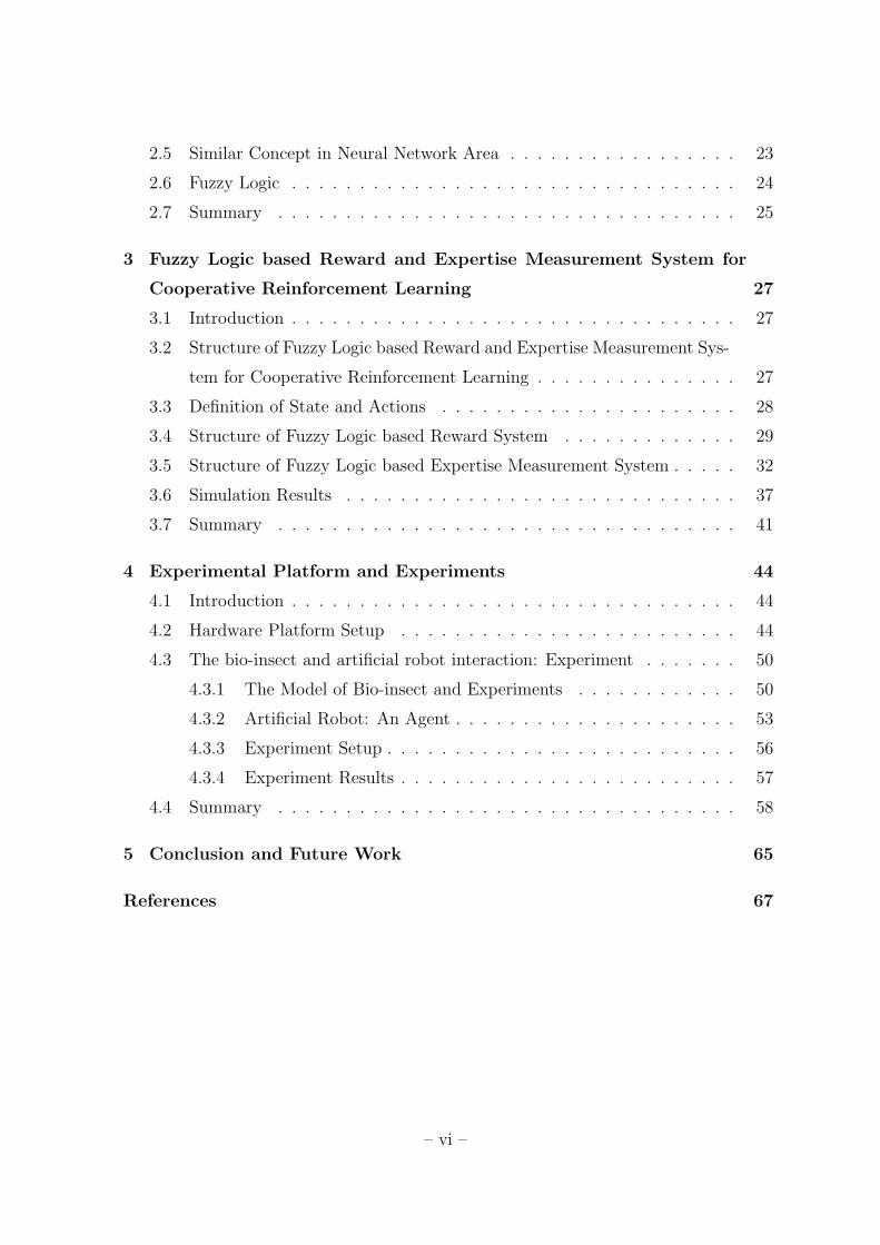
1.5 The trackball-computer interface[10]. . . . . . . . . . . . . . . . . . . . 7
1.6 The third pheromone-guided mobile robot, PheGMot-III, compared to
a 10 yen coin. The wingspan of a silkworm moth is about 4cm, so
PheGMot-III is as small as a silkworm moth[11]. . . . . . . . . . . . . . 7
1.7 Cockroach and Roach Bot[12]. . . . . . . . . . . . . . . . . . . . . . . . 8
1.8 The proposed leader robot which has a pump to spread chemical sources
in containers (up-side) and pheromone release system (down-side)[13]. . 9
– viii –

1.9 Representative pathway of cockroaches exposed to an air current con-
taining sex pheromone in different density. A:10−1, B:10−2, C:10−3,
D:10−4 and E:10−5 (EQ. Horizontal bar = 1m). Vertical arrow shows
direction of air current[14]. . . . . . . . . . . . . . . . . . . . . . . . . . 10
1.10 The proposed system[15]. (a) Experimental setup, (b) Definition of the
antennal position and (c) Definition of the parameters for locomotion . 11
2.1 The agent-environment interaction at discrete, finite world, choosing one
from a finite collection of actions at every time step [16]. . . . . . . . . 14
2.2 Flowchart of action selection in 2LRL-1.2[17]. . . . . . . . . . . . . . . 16
2.3 The Integration Scheme of RL and GA[18]. . . . . . . . . . . . . . . . . 18
2.4 Agent-based Decomposition (left) and Edge-based Decomposition (right)[19]. 18
2.5 A graphical representation of the edge-based and agent-based update
method after the transition from state s to s’[19]. (Edge-based Up-
date(left) and Agent-based Update(right)) . . . . . . . . . . . . . . . . 19
2.6 AliceBL observes all three states the same [9]. . . . . . . . . . . . . . . 22
2.7 A modular Connectionist Architecture[20]. . . . . . . . . . . . . . . . . 24
2.8 The Structure of Fuzzy Logic[4]. . . . . . . . . . . . . . . . . . . . . . . 25
3.1 The Flowchart of Proposed Framework[4]. . . . . . . . . . . . . . . . . 28
3.2 Proposed States and Actions for Bio-insect and Artificial Robot Interaction[4]. 29
3.3 Flowchart of the Fuzzy Logic based Reward System[4]. . . . . . . . . . 30
– ix –

3.4 The fuzzy Membership Functions for Fuzzy Logic based Reward System[4].
Figure (a) is the input membership functions for delta-distance, Figure
(b) is the input membership functions for angle of insect, Figure (c) is
the input membership functions for insect to goal distance and Figure
(d) is the output membership functions, where VB-very bad, BD-bad,
NM-normal, GD-good, VG-very good, CL-close, NR-normal, VF-very
far, FL-front left, LT-left, RR-rear, RT-right and FR-front right. . . . . 32
3.5 Random Movement Area (gray color area) of Insect by Robot Action[4]. 33
3.6 The Structure of Fuzzy Logic based Expertise Measurement System[4]. 33
3.7 The Fuzzy Membership Functions for Fuzzy Logic based Expertise Mea-
surement System[4]. (a) is the input membership functions for average
reward, (b) is the input membership functions for percentage of posi-
tive reward, (c) is the input membership functions for absolute average
reward and (d) is the output membership functions, where BD-bad,
NM-normal and GD-good. . . . . . . . . . . . . . . . . . . . . . . . . . 37
3.8 Results of Moving Trajectory and Distance between the Bio-insect and
the Desired Goal Point using Normal Reward Equation[4]. . . . . . . . 38
3.9 Results of Moving Trajectory and Distance between the Bio-insect and
the Desired Goal Point using Fuzzy Logic based Reward Algorithm[4]. . 39
3.10 Distance Results between the desired goal point and the bio-insect for
5 episodes(500 iteration * 5)[4]. (a)Non sharing, (b)Sharing with same
intensity and (c)Sharing with score weight. . . . . . . . . . . . . . . . . 42
– x –

3.11 Average Results of Arrival Iteration (a) and Average Results of Arrival
Distance of the Bio-insect’s Trajectory for 5 Episodes (b) [4]. . . . . . 43
4.1 E-Puck Robots[3]. . . . . . . . . . . . . . . . . . . . . . . . . . . . . . . 45
4.2 Structure of the E-puck Robot[21]. . . . . . . . . . . . . . . . . . . . . 46
4.3 Diagram of our Hardware Platform[3, 5]. This platform is composed of
bluetooth access point and main computer for control and image pro-
cessing. . . . . . . . . . . . . . . . . . . . . . . . . . . . . . . . . . . . 47
4.4 Bluetooth Access Point (left-side) and Camera (right-side)[5]. These are
installed the ceiling above our platform. . . . . . . . . . . . . . . . . . . 48
4.5 First proposed landmarks, which consisted of two different color mixture
(left-side), and program (right-side) to find heading angle and location
of each e-puck robot. . . . . . . . . . . . . . . . . . . . . . . . . . . . . 48
4.6 10 Proposed Landmarks for 10 e-puck robots to distribute each other
are suggested[5]. . . . . . . . . . . . . . . . . . . . . . . . . . . . . . . . 49
4.7 The GIST Formation Algorithm Software. After pushing ’Serial Con-
nection’ and ’GRAB Thread’ button, this software displays location and
heading angle of each e-puck robot. And then, based on above results,
this software send messages to each robot to make formation of G, I, S
and T continuously. . . . . . . . . . . . . . . . . . . . . . . . . . . . . . 49
4.8 (a) and (b) - The platform for BRIDS[5]. (c), (d), (e) and (f) - Formation
of 10 e-puck robots. Each (c) , (d), (e) and (f) image displays G, I, S
and T formation. . . . . . . . . . . . . . . . . . . . . . . . . . . . . . . 50
– xi –

4.9 The real image(left-side) is captured and detected(right-side) by our
hardware platform. Using same manner, this program can detect head-
ing angle and location of the bio-insect. . . . . . . . . . . . . . . . . . . 51
4.10 Simple Experimental Test using Allomyrina Dichotoma ((a)-female and
(b)-male) . . . . . . . . . . . . . . . . . . . . . . . . . . . . . . . . . . 52
4.11 The Stag Beetles (female (left side) and male (right side)) are used in
our experiment[4, 6]. . . . . . . . . . . . . . . . . . . . . . . . . . . . . 52
4.12 The Bio-insects for Simple Experiment. Actuation Sources : (01 and 02)
- Light and Vibration, (03 and 04) - Obstacle[4, 6], (05) - Wind(using
fans), (06) - Feed for the Bio-insect . . . . . . . . . . . . . . . . . . . . 54
4.13 The Developed E-puck Robot(left-side) and Its Structure(right-side)[6]. 55
4.14 Advanced Experiment[6]. Using Dual Fan Motors-(a), Different Tem-
perature of Air-(b) and Different Odor Sources-(c). . . . . . . . . . . . 60
4.15 The Proposed Structure of Spreading Odor Source Robot[6]. This robot
has two air pump motors to make airflow and one plastic bottle for
containing odor source. . . . . . . . . . . . . . . . . . . . . . . . . . . . 61
4.16 Saw Dust in Plastic Bottle from Habitat of the Bio-insect (left side) and
Habitat of the Bio-insect (right side)[6]. . . . . . . . . . . . . . . . . . 61
4.17 Real Image of Suggested Platform for Experiment[6]. . . . . . . . . . . 62
4.18 The Diagram of our Designed Platform of Experiment[6]. . . . . . . . . 62
– xii –

4.19 The Program of E-puck Robots Controller. Using this program, human
operator can control motion, actuation of each developed e-puck robot
via keyboard interface of main computer system. Also this software
displays heading angle and location of the bio-insect and the developed
e-puck robots in real time. . . . . . . . . . . . . . . . . . . . . . . . . 63
4.20 This is a real image taken from our designed experiment. The bio-insect
follows an artificial robot using its antenna from spreading odor source
provided by the artificial robot. . . . . . . . . . . . . . . . . . . . . . . 64
– xiii –

Chapter 1
Introduction
1.1 Bio-insect and artificial Robot Interaction based on Distributed Sys-
tems (BRIDS)
In machine learning, many researchers want to establish a new intelligent framework
for intelligent architecture, so they have studied robot intelligence based on dynamics.
It is, however, not easy to define intelligence for a particular system as dynamics due
to complexity and uncertainty; thus, there has been no dominant architecture for ar-
tificial intelligence. Indeed, it seems hard to establish a universal research framework
for improving intelligence of artificial robots, and it is challenging to apply robot in-
telligence theories to actual experimental environment. As a result, in this research,
we would like to develop a simple but fundamental intelligent framework for bio-insect
and artificial robot interaction. The task we are seeking in this research is very simple.
Our goal is to drive a bio-insect towards a desired point by a group of micro mobile
robots without any help from human. Bio-insect is an intelligence creature that can
choose their action based on their sensing information and communication methods.
They have their own intelligence to defend them against external threat. They have
a reaction against external driving force; so we can infer their movement pattern by
repetition. However, we cannot define their moving dynamics due to uncertainty and
– 1 –

complexity action results. In this thesis, we will employ machine learning theories for
bio-insect and artificial robot interaction. A representative research activity in this
research field is LEURRE [1, 2] that is a project to make a composite society of insects
and robots. They use cockroaches to understand flock habit and to control its move-
ment using artificial robots. Their research is successful in actuating the movement of
cockroaches using programmed artificial robots which behave as same as cockroaches
in their flock weared by pheromone source. But, we cannot find any intelligence theo-
ries in LEURRE. They just use cockroaches’ own pheromone mechanism; then change
their moving pattern. The research pursued in this work will be more comprehensive
because we attempt to understand, predict and control a real insect or animal using
intelligent theories.
1.2 Motivation and Goal
Our research, BRIDS, seeks a study on bio-insect and artificial robot interaction to
establish a new architectural framework for improving the intelligence of service robot.
One of the main research goals is to drive bio-insect by coordination of a group of
micro mobile robots towards a desired goal point. The research includes establishment
of hardware/software for bio-insect and artificial robot interaction and synthesis of
distributed sensing, distributed decision, and distributed control systems for building
a community composed of bio-insect and artificial robots. Fig. 1.2 explains how to
compose and connect subsystems.
Distributed sensing is for the recognition and detection of mobile bio systems, and
– 2 –

Figure 1.1: Our main goal is to drive a bio-insect towards desired goal point using a
group of micro mobile robots.
Figure 1.2: Flowchart of proposed community composed of distributed decision, dis-
tributed control and distributed sensing. Subsystems are connected in a feedback loop
manner[3].
for the construction of wireless sensor network to locate artificial robots and bio-insect.
Distributed decision contains learning of reactions of bio-insect repetitively for a certain
form of inputs. It aims at finding which command and actuation do drive bio-insect
towards a desired goal point or drive away from the target position. Reinforcement
– 3 –

learning algorithm will be designed to generate penalty or rewards on a set of ac-
tions. Distributed decision stores the state of current action and its outputs, which
are closely associated with the future event, into memory. Then it selects commands
and outcomes of past actions for the current closed-loop learning. Thus the synthesis
of recursive learning algorithm on the basic of storage and selection procedure along
the learning domain will be of main interest in the distributed decision. Distributed
control includes control and deployment of multi-mobile robots via coordination, and
design of optimally distributed-control algorithm based on the coordination. It learns
how bio-insect reacts upon relative speed, position, orientation between multi-mobile
robots and bio-insect. The ultimate goal of this research is thus to establish a new
theoretical framework for robot learning via a recursive sequential procedure of the
distributed sensing, decision and control systems. For convenience our on-going re-
search is called Bio-insect and artificial Robot Interaction on the base of Distributed
Systems (BRIDS). Fig. 1.3 illustrates architecture of our research (BRIDS).
The research on bio-insect and artificial robot interaction will provide a fundamen-
tal theoretical framework for human and robot interaction. The applications include
service robot, cleaning robot, intelligence monitoring systems, intelligent building, and
ITS. This research is for a control of model-free bio-systems; thus it could be used for
a control of complex systems such as metropolitan transportation control and envi-
ronmental monitoring, which cannot be readily modeled in advance. The result can
also be used to attract and expel harmful insects such as cockroach via interaction and
intra-communication.
– 4 –

Figure 1.3: Architecture of BRIDS: This figure shows how to relate individual sub-
systems. The first step is to construct distributed sensing, distributed decision and
distributed control systems. Then, we make a closed-system based on feedback loop
for learning and exchange of knowledge for sharing information[3].
1.3 Related Works
1.3.1 Leurre
Leurre[1, 2] is a project on building and controlling mixed societies composed of
insects and robots. Their main goals are to study of mixed society to develop and
control. As seen in the Fig. 1.4, cockroaches and insbot are together in testbed. To co-
exist with cockroaches, insbot has some known knowledge of behavior and pheromone
[22]. In normal environment, cockroaches run away from insbot when it moves. Insbot
is controlled by wireless network, and it is equipped with small size IR proximity sensor,
– 5 –

light sensor, linear camera, temperature sensor and sensors to detect pheromone [23].
Goal of this robot is to behave like an insect and to be able to influence the society.
Figure 1.4: Cockroaches and Insbot robot[1].
1.3.2 Locomotion control of bio-robotic system via electric stimulation
In [10], they show the direct control of cockroach via electric stimulation. As seen
in Fig. 1.5, they made a trackball-computer interface to find the movement based on
stimulus generator. This stimulus generator is connected in cockroach by portable
stimulation unit that gives some pulse signal. And then they find the movement by
trackball-computer interface. Based on expertise, they made an autonomous electronic
backpack. It uses two photosensors that made a cockroach to follow the black line.
1.3.3 Pheromone-guided mobile robots
In [11], they propose a mobile robot which detects a female silkworm pheromone.
Some insects have pheromone that uses for communication or copulation. When a male
silkworm moth found a pheromone of female silkworm moth, it shows some behavior to
– 6 –
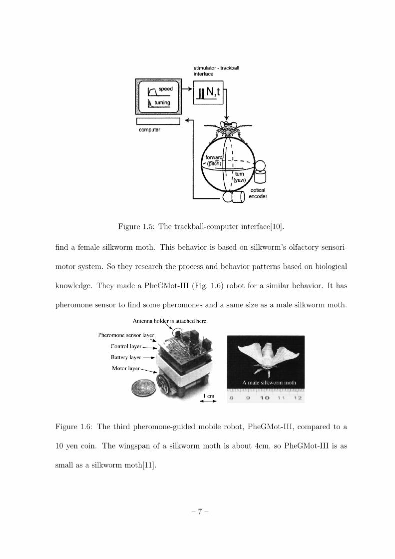
Figure 1.5: The trackball-computer interface[10].
find a female silkworm moth. This behavior is based on silkworm’s olfactory sensori-
motor system. So they research the process and behavior patterns based on biological
knowledge. They made a PheGMot-III (Fig. 1.6) robot for a similar behavior. It has
pheromone sensor to find some pheromones and a same size as a male silkworm moth.
Figure 1.6: The third pheromone-guided mobile robot, PheGMot-III, compared to a
10 yen coin. The wingspan of a silkworm moth is about 4cm, so PheGMot-III is as
small as a silkworm moth[11].
– 7 –

1.3.4 Roach Bot
Roach bot[12](Fig. 1.7 (Left)) is a robot controlled by cockroach. As seen in Fig. 1.7
(Right), cockroach is placed on the top of trackball. When some obstacle is detected by
sensor of roach bot, it gives some stimulus by electric light. Cockroach is a nocturnal
insect that hates the light. Because of this reason, when cockroach is exposed to light,
it runs away to avoid light. These movements are caught by trackball sensor and it
moves by following the movement of cockroach.
Figure 1.7: Cockroach and Roach Bot[12].
1.3.5 Guiding robot’s behaviors using pheromone communication
In [13], they propose on-going project to investigate the usage of pheromones for
communication to each other robots inspired by social insect which compose a society
using pheromone sources. As their society, proposed robots are composed two types
such as leader robot and responding robot. To apply this mechanism, the leader robot
have actuator to spread chemical sources as introduced in Fig. 1.8, and other robots
– 8 –

can detect it by attached gas sensor. Without any electric wireless communication
method, they show two type behaviors; if 1st chemical source spread some area from
the leader robot, other robots follow the leader robot, or if 2st chemical source spread,
they go away from the leader robot. Similarly, localization using odor source is also
studied in robotics area. As a result, survey paper of robot odor localization is already
published [24].
Figure 1.8: The proposed leader robot which has a pump to spread chemical sources
in containers (up-side) and pheromone release system (down-side)[13].
– 9 –

1.3.6 Behavior of cockroach by pheromone source
Cockroach is frequently used to study their behavior or mechanism because of their
strong life force and active behavior. In [25, 26, 14], they introduce movement of
cockroach by sex pheromone sources in air flow. In Fig.1.9, this result shows that the
highest density of sex pheromone in air can influence their movement. As a result of
this papers, we can sure that pheromone source can affect their movement.
Figure 1.9: Representative pathway of cockroaches exposed to an air current containing
sex pheromone in different density. A:10−1, B:10−2, C:10−3, D:10−4 and E:10−5 (EQ.
Horizontal bar = 1m). Vertical arrow shows direction of air current[14].
1.3.7 Antennal and locomotor responses to attractive and aversive odor in
the searching cockroach
In [15], they also research reactions using different odor stimulate that is female-
derived odor and limonene. And then, using their own hardware system as seen in
– 10 –

Fig.1.10, they check movement of cockroach and movement of their antenna proposed
video camera and optical mouse system when cockroach stimulate specific odor sources.
Figure 1.10: The proposed system[15]. (a) Experimental setup, (b) Definition of the
antennal position and (c) Definition of the parameters for locomotion
1.4 Organization of the thesis
This thesis is divided into three major parts. In chapter 2 , this chapter presents
related backgound material of this research. Reinforcement learning, which is a kind
of machine learning algorithm and a key point in our framework, is introduced in
– 11 –
section 2.2 with Q-learning that is a important part in reinforcement learning. In
order to obtain precise and fast results, cooperative reinforcement learning is required
in this research. So, in section 2.3, this topic is simply surveyed including an area of
expertise algorithm which is intoduced in section 2.4. In our survey work, we found
similar concept in neural network area is introduced in 2.5. In section 2.6, fuzzy logic
employed in our fuzzy logic based reward and expertise system introdued in chapter 3
is introduced.
In chapter 3, our framework is proposed which is called fuzzy logic based reward
and expertise system for cooperative reinforcement learning. In order to introduce our
framework, in section 3.2, present structure of fuzzy logic based reward and expertise
measurement system. And then, in section 3.3, 3.4 and 3.5, these sections introduce
definition of state and action, structure of fuzzy logic based reward system, and struc-
ture of fuzzy logic based expertise measurement system respectively. Finally, in section
3.6. simulation results of this framework are given.
In chapter 4, this chapter introduce our hardware system we built in section 4.2.
And then, actuation experiment setup and results are given in section 4.3.
Finally, conclusion and future work are given in chapter 5.
– 12 –

Chapter 2
Background Material
2.1 Introduction
In this chapter, we introduce basic key theories of our research framework which
are reinforcement learning, cooperative reinforcment learing, area of expertise in coop-
erative reinforcement learning, similar concept of area of expertise concept in neural
network and fuzzy logic.
2.2 Reinforcement Learning
Fundamental principle of reinforcement learning [16][27] is a reward signal-based
trial and error iteration process. On the basis of Markov Decision Process (MDP),
which is called action-repeating process, the iteration process makes an attempt to
get a maximum reward. As seen in Fig. 2.1, this iteration process could be defined
as a discrete set of environments, a discrete set of agent actions and a discrete set of
reinforcement learning signals.
2.2.1 Q-learning
Q-learning[28] is a popular method in reinforcement learning area. Using initialized
Q(s, a) table, it updates its immediate reward in each state (s) by selected action (a).
– 13 –
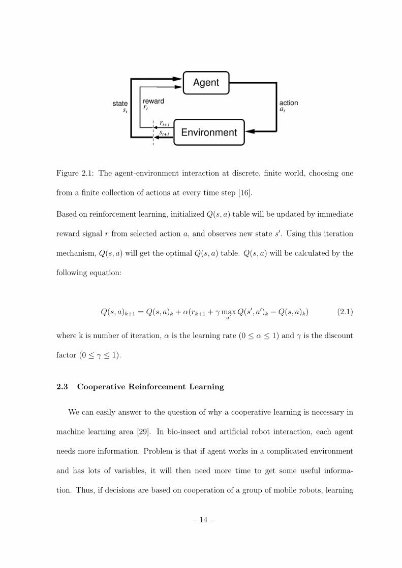
Figure 2.1: The agent-environment interaction at discrete, finite world, choosing one
from a finite collection of actions at every time step [16].
Based on reinforcement learning, initialized Q(s, a) table will be updated by immediate
reward signal r from selected action a, and observes new state s′. Using this iteration
mechanism, Q(s, a) will get the optimal Q(s, a) table. Q(s, a) will be calculated by the
following equation:
Q(s, a)k+1 = Q(s, a)k + α(rk+1 + γmaxa′
Q(s′, a′)k −Q(s, a)k) (2.1)
where k is number of iteration, α is the learning rate (0 ≤ α ≤ 1) and γ is the discount
factor (0 ≤ γ ≤ 1).
2.3 Cooperative Reinforcement Learning
We can easily answer to the question of why a cooperative learning is necessary in
machine learning area [29]. In bio-insect and artificial robot interaction, each agent
needs more information. Problem is that if agent works in a complicated environment
and has lots of variables, it will then need more time to get some useful informa-
tion. Thus, if decisions are based on cooperation of a group of mobile robots, learning
– 14 –

speed will become faster. In cooperative reinforcement learning [29], different types of
learning algorithms exist. Most part of methods are based on game theory using nash
equilibrium and zero-sum game, hierarchical(layer) architecture or mixed up another
learning algorithms. In this section, we focus on cooperative reinforcement learning
methods. In [30], they consider two agents that have diametrically opposed goals.
This method allows us to use a single reward function that one agent tries to maxi-
mize and the other, called the opponent tries to minimize. This method is called a
two-player zero-sum markov game or called minmax-Q learning algorithm, which can
be summarized as follow.
V (s) = maxπ∈PD(A)
mino∈O
∑a∈A
Q(s, a, o)πa (2.2)
Q∗(s, a, o) = R(s, a, o) + γ∑s′T (s, a, o, s′)V (s′) (2.3)
Eq. (2.2) is the value of a state s, and s′ in markov game and (2.3) is the expected
reward for taking action a when another agent chooses opponent action o. In [31], they
use average reward-based learning such as the Monte-Carlo algorithm for task-level
multirobot systems that make two levels. Action-level systems perform missions based
on reactive behavior, whereas task-level systems perform missions at a higher level by
decomposing them into subtasks. In [17], they use two-level reinforcement learning
with communication (2LRL) method. In the first level, agents learn how to select their
target and then they select the action directed to their target in the second level.
This algorithm uses different Q-tables (QFollow, QPrey, QOwnp, QOwnP, QOther)
that have their own purpose and learning mechanism. Of particular interest in this
– 15 –

Figure 2.2: Flowchart of action selection in 2LRL-1.2[17].
research is that standard Q-learning algorithm is extended to multi-agent environments.
This two level decision mechanism uses catching small and big prey in a discrete grid-
world environment. In [32], they propose Team Q-learning algorithm. This learning
method is based on Q-learning and shows how they define the environment, state
action, and reward function more exactly. The reward function is generated by
R = w1 ·Rdistance + w2 ·Rrotation + w3 ·Robstacle (2.4)
where w1 + w2 + w3 = 1. Each reward functions define distance of goal location,
rotation behavior of the box, and obstacle avoidance that is calculated by each weight
result:
(a∗1, · · · , a∗n) ∈ arg max(a∗1,···,an)
Q(s, a1, · · · , an) (2.5)
– 16 –

Q(s, a∗1, · · · , a∗n)k+1 = (1− ε)Q(s, a∗1, · · · , a∗n)k
+ε(rk+1 + β maxa1,···,an
Q[s′, a1, · · · , an]k)
(2.6)
The joint action set is defined by (2.7) and Team Q-learning equation is given by
(2.5). As seen in this equation, the team-Q-learning method is composed of an arrange
of Q-learning. Because of this result, they got bad experiment results that single agent
Q-learning shows more good performance than team-Q-learning. In [18], they show a
integrated sequential Q-learning and genetic algorithm. Sequential Q-learning equation
is given by (2.7). In eq(2.7), ε means learning rate and µ means discount rate. Three
main elements of genetic algorithm operators are selection, crossover and mutation.
For using these elements, gene will be changed and calculated by fitness function. This
fitness function shows which gene will give a good result. Fig. 2.3 shows logical flow
between sequential reinforcement learning and genetic algorithm.
Q(s, a1j , a
2j , · · · , aij)k+1 = (1− ε)Q(s, a1
j , a2j , · · · , aij)k
+ε(rk+1 + µ maxa1,a2,···,ai
Q[s′, a1, a2, · · · , ai]k)
(2.7)
In [19], they propose more developed Sparse Cooperative Q-learning that is com-
posed on agent-base and edge-base based on structure of coordination graph(CG).
As seen in Fig. 2.4, it shows how each neighbor interacts with Qi and Qij. Agent-
– 17 –

Figure 2.3: The Integration Scheme of RL and GA[18].
Figure 2.4: Agent-based Decomposition (left) and Edge-based Decomposition
(right)[19].
based decomposition method will update Qi by equation (2.8) for each agent i individu-
ally. Edge-based decomposition method will update Qij by equation (2.9)for the agent
i and neighbor agents j as an edge-based update method. Based on the edge-based
update method, agent-based update will be updated by equation (2.10).
– 18 –

Figure 2.5: A graphical representation of the edge-based and agent-based update
method after the transition from state s to s’[19]. (Edge-based Update(left) and Agent-
based Update(right))
Qi(si, ai)k+1 = Qi(si, ai)k + α[Ri(s, a)k+1 + γQi(s′
i, a∗i )k −Qi(si, ai)k] (2.8)
Qij(sij, ai, aj)k+1 = Qij(sij, ai, aj)k
+α[Ri(s, a)k+1
|Γ(i)|+Rj(s, a)k+1
|Γ(j)|+ γQij(s
′ij, a
∗i , a∗j)k −Qij(sij, ai, aj)k] (2.9)
Qij(sij, ai, aj)k+1 = Qij(sij, ai, aj)k
+ α∑m∈i,j
Rm(s, a)k+1 + γQm(s′m, a∗m)k −Qm(sm, am)k
|Γ(m)|(2.10)
where s is state, a is action, Γ(m) is neighbor of agent i and k is number of itera-
tion. From the literature search, we can find lots of papers in the field of cooperative
reinforcement learning. In [33], they show lots of methods and problem domains. In
– 19 –
the latest of survey article [34], the paper also shows and classifies many ways of coop-
erative learning algorithm. But we cannot find any survey on area of expertise concept.
So in the next section, we will introduce area of expertise (AOE).
2.4 Area of Expertise
In this section, we introduce area of expertise (AOE) in cooperative reinforcement
learning area. In real world, many people have one more merits on their capability.
In reinforcement learning, AOE has been recently introduced. An expertise concept of
[7] tells why AOE is critical in cooperative reinforcement learning. A similar approach
called advice-exchange was studied in [35]. But a difference between advice-exchange
and area of expertise is that advice-exchange is based on previous experience concept
and area of expertise is learning cooperation at which agent got more expertise. So in
this section, we explain expertise measure, meaning of area of expertise, and weight
strategy sharing (WSS).
2.4.1 Area of Expertise
Area of expertise is to show which agent is more expertise in part of knowledge do-
main. In [7], they explain two different aspects on expertise. In behavioral knowledge-
base, a better and more rational behavior agent is more expertise and in structural
points of view, a better and more reliable knowledge agent in somewhere is more ex-
pertise.
– 20 –

2.4.2 Expertise Measure
In [7], they introduce methods for expertise evaluation. In cooperative reinforce-
ment learning area, we do not know which agent is more expertise or which agent
can find an optimal action. The expertise measure can help to calculate expertise.
Various ways of expertise measure [7], [8], [9] show how to calculate or process re-
ward(reinforcement signal) of each agent. As seen in table 2.1, there are different
methods for measuring expertise. These expertise measuring methods indicate how to
calculate reinforcement signals from [7], [8], [9]. Using this method, each method will
generate different results in different environment. Because of this reason, if we want
to adapt some expertise measure, it should be chosen based on environment.
2.4.3 Weight Strategy Sharing
Weight strategy sharing (WSS) is also a method to find area of expertise from
multiple agents. WSS is to show how to calculate expertise value in weight. Similar
weight concept of reinforcement learning is found in [36]. Reward is updated by taking
account of other agent’s location information such as:
R =w ·Rw +
∑ni=1Ri
w + n(2.11)
where w is the agent’s reward weighting result, Rw is the agent’s reward due to the
agent foraging food, summation of the reward Ri of agents n located in agent’s visual
range. The equation (2.11) shows how much emphasis is placed on the agent’s reward
compared to that of other agents.
– 21 –

Next, we review weight strategy sharing algorithm [7], [8], [9]. For area of expertise,
weight Wipj is calculated by
Wipj =
1− αi, if j = i;
αiepj−epi∑
k∈Epl(epk−epi)
, if j ∈ Epi;
0, otherwise.
(2.12)
where i indicates the learner agent, j is an index on the other agents, p stands for
different local parts of Q-table and epj is the expertness of agent j on portion p of the Q-
table and αi indicates how much each agent relies on the others. Reference [7] explains
a more advanced case when the agent knows AOE. In [9], they do an experiment using
two alice robot. Interesting part of this experiment is that each robot has blinded-
sensor called AliceBL (blinded left sensor) and AliceBR (blinded right sensor). In this
situation, they adapt area of expertise to make a good performance.
Figure 2.6: AliceBL observes all three states the same [9].
In [37], they propose adaptive weight strategy sharing (AdpWSS) (2.13) and regret
measure (2.14). Equation (2.13) is a probability of sharing knowledge to another agent.
This probability is based on weight result of each agent:
– 22 –

Probs =
0, if |Wi −Wj| ≤ Th1,
1, if |Wi −Wj| ≥ Th2,
|Wi−Wj |−Th1
Th2−Th1, otherwise.
(2.13)
where Th1, Th2 are threshold result and wi, wj are weight result of wi, wj. The
regret measure can be used as an alternative of strategy sharing. Eq. (2.14) is based
on uncertain bounds of both actions where each lb() and ub() means lower limit of
estimated state-action value and upper limit of approximated state-action value based
on (2.15).
regret(st+1) = −lb(q(st+1, a1)− ub(Q(st+1, a2))) (2.14)
Bound(Qt(st, a)) = QT (ST , a)± ta2,k−1
s√k
(2.15)
Using this method, expertness will be calculated by the following equation:
expertnessm(st) = 1− 1
1 + exp(−b ∗ regret(st))(2.16)
In [38], they use expertise sharing concept for designing a biding-agent for electricity
markets.
2.5 Similar Concept in Neural Network Area
Weight concept is also found in neural network area. Each neuron is connected by
weight results. So it is also important to choose and get the efficient weight result in
– 23 –

long time. As seen in Fig. 2.7, expert networks are connected by gating network. The
fig. 2.7 from [20], called a modular connectionist architecture, shows how to connect
networks. Each weight is changed by Q-learning based on neural network and each
expert network is seen as similar as area of expertise.
Figure 2.7: A modular Connectionist Architecture[20].
In [39], they explain the method to connect the weights of the gating networks
based on backpropagation algorithm.
2.6 Fuzzy Logic
In control applications, fuzzy logic is popularly used for control architecture. In
human body system, our sensor system does not know the exact sensing quantities.
For example, we just feel the room temperature such as warm, cold or hot. If we want
a warm room temperature, we can turn on or off heater switch based on our feeling.
This linguistic variable is a key point of fuzzy logic. Fuzzy logic is introduced in [40].
– 24 –
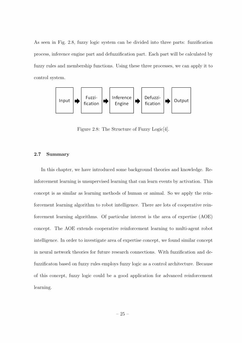
As seen in Fig. 2.8, fuzzy logic system can be divided into three parts: fuzzification
process, inference engine part and defuzzification part. Each part will be calculated by
fuzzy rules and membership functions. Using these three processes, we can apply it to
control system.
Figure 2.8: The Structure of Fuzzy Logic[4].
2.7 Summary
In this chapter, we have introduced some background theories and knowledge. Re-
inforcement learning is unsupervised learning that can learn events by activation. This
concept is as similar as learning methods of human or animal. So we apply the rein-
forcement learning algorithm to robot intelligence. There are lots of cooperative rein-
forcement learning algorithms. Of particular interest is the area of expertise (AOE)
concept. The AOE extends cooperative reinforcement learning to multi-agent robot
intelligence. In order to investigate area of expertise concept, we found similar concept
in neural network theories for future research connections. With fuzzification and de-
fuzzificaton based on fuzzy rules employs fuzzy logic as a control architecture. Because
of this concept, fuzzy logic could be a good application for advanced reinforcement
learning.
– 25 –
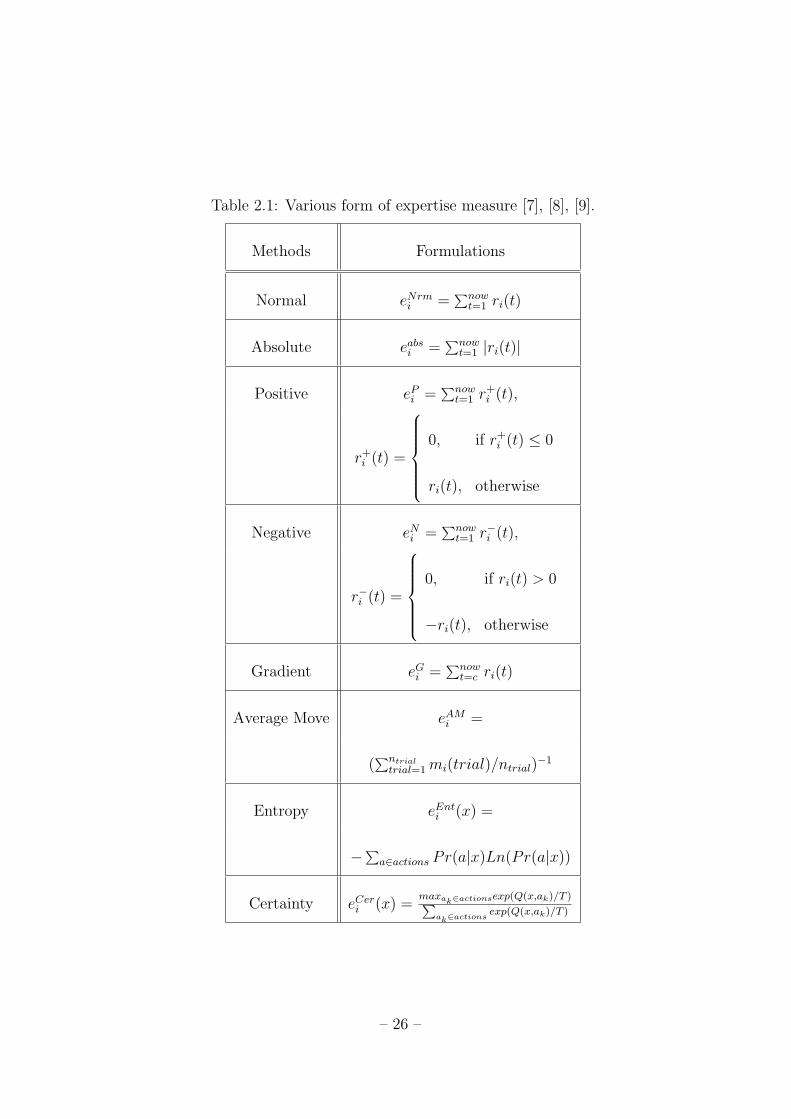
Table 2.1: Various form of expertise measure [7], [8], [9].
Methods Formulations
Normal eNrmi =∑nowt=1 ri(t)
Absolute eabsi =∑nowt=1 |ri(t)|
Positive ePi =∑nowt=1 r
+i (t),
r+i (t) =
0, if r+
i (t) ≤ 0
ri(t), otherwise
Negative eNi =∑nowt=1 r
−i (t),
r−i (t) =
0, if ri(t) > 0
−ri(t), otherwise
Gradient eGi =∑nowt=c ri(t)
Average Move eAMi =
(∑ntrialtrial=1mi(trial)/ntrial)
−1
Entropy eEnti (x) =
−∑a∈actions Pr(a|x)Ln(Pr(a|x))
Certainty eCeri (x) =maxak∈actionsexp(Q(x,ak)/T )∑
ak∈actionsexp(Q(x,ak)/T )
– 26 –

Chapter 3
Fuzzy Logic based Reward and Expertise
Measurement System for Cooperative Re-
inforcement Learning
3.1 Introduction
The research pursued in this work will be more comprehensive because we attempt
to understand, predict and control a real insect or animal using intelligent theories.
This chapter introduces how we can solve this problem using intelligence theories ex-
planed avove chapter. In this chapter, we establish our framework for bio-insect and
artificial robot interaction and address simulation results. And then summary will be
given in final section.
3.2 Structure of Fuzzy Logic based Reward and Expertise Measurement
System for Cooperative Reinforcement Learning
Fig. 3.1 is a flowchart of our fuzzy logic based reward system for cooperative re-
inforcement learning framework. This framework consists of fuzzy logic based reward
for reinforcement learning part and fuzzy logic based expertise measurement part. In
fuzzy logic based reward system part, each agent can learn their knowledge from fuzzy
– 27 –

logic based reinforcement reward process. In fuzzy logic based expertise measurement
part, each agent can share their knowledge using area of expertise concept and fuzzy
logic. More exact information is introduced in following sections.
Figure 3.1: The Flowchart of Proposed Framework[4].
3.3 Definition of State and Actions
Fig. 3.2 shows proposed states and actions for bio-insect and artificial robot interac-
tion. Each robot has a defined set of states according to distances between a bio-insect
to an agent: r(0 to 10, 10 to 30, 30 to 60, 60 to 100 and 100 to infinity), which are
divided by 16 discrete angles (θ) of goal position from insect and eight discrete angles
of robot position φ. On the basis of these states, each agent can learn knowledge from
their reward experience, and then each agent knows which location is better for driving
the bio-insect to the goal point by iteration.
– 28 –

Figure 3.2: Proposed States and Actions for Bio-insect and Artificial Robot
Interaction[4].
3.4 Structure of Fuzzy Logic based Reward System
In reinforcement learning area, how to generate an exact reward signal function is
important when agents do learn. Most of papers use equations to generate a reward
signal due to action results. However, it is hard work to make some equations. In
our research, fuzzy logic is a good application to generate a reward signal function.
If we could make membership functions and fuzzy rules, fuzzy logic would generate
an exact reward for our purpose. So we use fuzzy logic for reward processes. Fig. 3.3
shows how to generate a reward signal due to action (a) in state (s). In this simulation,
input signals (results from an action (a)) are delta-distance (distance variation between
bio-insect to the goal point), angle of insect and distance between bio-insect and the
goal point. Each input signal transforms into crisp values by fuzzification process,
and then this crisp value transforms into a reward signal within (-1 to 1) using the
– 29 –

defined membership functions and fuzzy rules by defuzzification process. Fig. 3.4 is
membership functions, and table 3.1 is 69 fuzzy rules for fuzzy logic based reward
systems. As seen in table 3.1, if delta distance is 10, and angle is 0 or 360, high class
(A or B) output membership function will be chosen. Distance is also used in choosing
output membership function. If distance is in VF, delta distance will be used with a
more probability for choosing high class membership function than angle. If distance is
in CL, angle will be used with a more probability for choosing high class membership
function than delta distance.
Figure 3.3: Flowchart of the Fuzzy Logic based Reward System[4].
As mentioned before, the movement of insect is a kind of random. Therefore, for
simulations, it is supposed that each agent does an action in state (s), then an insect
will move to desire response point; but the reaction has some uncertainties, white
Gaussian noise signal is added to the insect’s movement. We define the movement area
by an action (a) as shown in Fig. 3.5. In this movement, amount of random signals will
be changed by distance state between bio-insect and artificial robot. If robot moves on
to near side insect, insect will move to another point with small randomness. If robot
moves to good actuation point (defined), insect will move to another point with good
direction. If robot moves to far side insect, insect will move to another point with big
– 30 –

Table 3.1: Fuzzy Rules for the Fuzzy Logic based Reward System[4].
1. If (Delta Distance is VB) and (Angle is RR) and (Distance is VF) then (output1 is E)2. If (Delta Distance is VB) and (Angle is RR) and (Distance is NM) then (output1 is E)3. If (Delta Distance is VB) and (Angle is RR) and (Distance is CL) then (output1 is D)4. If (Delta Distance is VB) and (Angle is LT) and (Distance is VF) then (output1 is D)5. If (Delta Distance is VB) and (Angle is LT) and (Distance is NM) then (output1 is D)6. If (Delta Distance is VB) and (Angle is LT) and (Distance is CL) then (output1 is C)7. If (Delta Distance is VB) and (Angle is RT) and (Distance is VF) then (output1 is D)8. If (Delta Distance is VB) and (Angle is RT) and (Distance is NM) then (output1 is D)9. If (Delta Distance is VB) and (Angle is RT) and (Distance is CL) then (output1 is C)10. If (Delta Distance is BD) and (Angle is RR) and (Distance is VF) then (output1 is E)11. If (Delta Distance is BD) and (Angle is RR) and (Distance is NM) then (output1 is E)12. If (Delta Distance is BD) and (Angle is RR) and (Distance is CL) then (output1 is D)13. If (Delta Distance is BD) and (Angle is LT) and (Distance is VF) then (output1 is D)14. If (Delta Distance is BD) and (Angle is LT) and (Distance is NM) then (output1 is D)15. If (Delta Distance is BD) and (Angle is LT) and (Distance is CL) then (output1 is C)16. If (Delta Distance is BD) and (Angle is RT) and (Distance is VF) then (output1 is D)17. If (Delta Distance is BD) and (Angle is RT) and (Distance is NM) then (output1 is D)18. If (Delta Distance is BD) and (Angle is RT) and (Distance is CL) then (output1 is D)19. If (Delta Distance is BD) and (Angle is FL) and (Distance is VF) then (output1 is D)20. If (Delta Distance is BD) and (Angle is FL) and (Distance is NM) then (output1 is D)21. If (Delta Distance is BD) and (Angle is FL) and (Distance is CL) then (output1 is C)22. If (Delta Distance is BD) and (Angle is FR) and (Distance is VF) then (output1 is D)23. If (Delta Distance is BD) and (Angle is FR) and (Distance is NM) then (output1 is D)24. If (Delta Distance is BD) and (Angle is FR) and (Distance is CL) then (output1 is C)25. If (Delta Distance is NM) and (Angle is RR) and (Distance is VF) then (output1 is C)26. If (Delta Distance is NM) and (Angle is RR) and (Distance is NM) then (output1 is D)27. If (Delta Distance is NM) and (Angle is RR) and (Distance is CL) then (output1 is D)28. If (Delta Distance is NM) and (Angle is LT) and (Distance is VF) then (output1 is D)29. If (Delta Distance is NM) and (Angle is LT) and (Distance is NM) then (output1 is D)30. If (Delta Distance is NM) and (Angle is LT) and (Distance is CL) then (output1 is C)31. If (Delta Distance is NM) and (Angle is RT) and (Distance is VF) then (output1 is D)32. If (Delta Distance is NM) and (Angle is RT) and (Distance is NM) then (output1 is D)33. If (Delta Distance is NM) and (Angle is RT) and (Distance is CL) then (output1 is C)34. If (Delta Distance is NM) and (Angle is FL) and (Distance is VF) then (output1 is C)35. If (Delta Distance is NM) and (Angle is FL) and (Distance is NM) then (output1 is C)36. If (Delta Distance is NM) and (Angle is FL) and (Distance is CL) then (output1 is B)37. If (Delta Distance is NM) and (Angle is FR) and (Distance is VF) then (output1 is C)38. If (Delta Distance is NM) and (Angle is FR) and (Distance is NM) then (output1 is C)39. If (Delta Distance is NM) and (Angle is FR) and (Distance is CL) then (output1 is B)40. If (Delta Distance is GD) and (Angle is RR) and (Distance is VF) then (output1 is B)41. If (Delta Distance is GD) and (Angle is RR) and (Distance is NM) then (output1 is C)42. If (Delta Distance is GD) and (Angle is RR) and (Distance is CL) then (output1 is C)43. If (Delta Distance is GD) and (Angle is LT) and (Distance is VF) then (output1 is B)44. If (Delta Distance is GD) and (Angle is LT) and (Distance is NM) then (output1 is B)45. If (Delta Distance is GD) and (Angle is LT) and (Distance is CL) then (output1 is C)46. If (Delta Distance is GD) and (Angle is RT) and (Distance is VF) then (output1 is B)47. If (Delta Distance is GD) and (Angle is RT) and (Distance is NM) then (output1 is B)48. If (Delta Distance is GD) and (Angle is RT) and (Distance is CL) then (output1 is C)49. If (Delta Distance is GD) and (Angle is FL) and (Distance is VF) then (output1 is B)50. If (Delta Distance is GD) and (Angle is FL) and (Distance is NM) then (output1 is B)51. If (Delta Distance is GD) and (Angle is FL) and (Distance is CL) then (output1 is C)52. If (Delta Distance is GD) and (Angle is FR) and (Distance is VF) then (output1 is B)53. If (Delta Distance is GD) and (Angle is FR) and (Distance is NM) then (output1 is B)54. If (Delta Distance is GD) and (Angle is FR) and (Distance is CL) then (output1 is C)55. If (Delta Distance is VG) and (Angle is RR) and (Distance is VF) then (output1 is B)56. If (Delta Distance is VG) and (Angle is RR) and (Distance is NM) then (output1 is B)57. If (Delta Distance is VG) and (Angle is RR) and (Distance is CL) then (output1 is C)58. If (Delta Distance is VG) and (Angle is LT) and (Distance is VF) then (output1 is A)59. If (Delta Distance is VG) and (Angle is LT) and (Distance is NM) then (output1 is A)60. If (Delta Distance is VG) and (Angle is LT) and (Distance is CL) then (output1 is B)61. If (Delta Distance is VG) and (Angle is RT) and (Distance is VF) then (output1 is A)62. If (Delta Distance is VG) and (Angle is RT) and (Distance is NM) then (output1 is A)63. If (Delta Distance is VG) and (Angle is RT) and (Distance is CL) then (output1 is B)64. If (Delta Distance is VG) and (Angle is FL) and (Distance is VF) then (output1 is A)65. If (Delta Distance is VG) and (Angle is FL) and (Distance is NM) then (output1 is A)66. If (Delta Distance is VG) and (Angle is FL) and (Distance is CL) then (output1 is A)67. If (Delta Distance is VG) and (Angle is FR) and (Distance is VF) then (output1 is A)68. If (Delta Distance is VG) and (Angle is FR) and (Distance is NM) then (output1 is A)69. If (Delta Distance is VG) and (Angle is FR) and (Distance is CL) then (output1 is A)
– 31 –

Figure 3.4: The fuzzy Membership Functions for Fuzzy Logic based Reward System[4].
Figure (a) is the input membership functions for delta-distance, Figure (b) is the input
membership functions for angle of insect, Figure (c) is the input membership functions
for insect to goal distance and Figure (d) is the output membership functions, where
VB-very bad, BD-bad, NM-normal, GD-good, VG-very good, CL-close, NR-normal,
VF-very far, FL-front left, LT-left, RR-rear, RT-right and FR-front right.
randomness.
3.5 Structure of Fuzzy Logic based Expertise Measurement System
In this system, we use three agents which have own state and can do sequent serial
action for cooperative reinforcement learning. After one episode (500 iteration), each
agent has their own state and action information. In order to combine their knowledge,
our framework is developed based on area of expertise concept from [41, 42, 43]. In the
– 32 –

Figure 3.5: Random Movement Area (gray color area) of Insect by Robot Action[4].
framework, we need to find which agent is more expert at a certain environment. If
each agent is an expert at a certain environment, each agent can share their knowledge
without any additional experience. For this reason, each agent can learn with a faster
speed and a more reliable information. Each agent can show a better performance
than a single learning method. Fig. 3.6 is a structure of fuzzy logic based expertise
measurement system.
Figure 3.6: The Structure of Fuzzy Logic based Expertise Measurement System[4].
– 33 –

In our system, we use a combined fuzzy logic based expertise measurement system.
The fuzzy logic based expertise measurement system uses three inputs. Each input
signal is average reward, percentage of reward action and absolute average reward.
Each measurement value will be calculated by equations (3.1) to (3.3).
Average reward = (iteration∑i=1
ri)/iteration (3.1)
Percentage of positive reward = (iteration∑i=1
ri)/iteration,
where ri =
1, if ri ≥ 0
0, otherwise
(3.2)
Abs average reward = (iteration∑i=1
|ri|)/iteration (3.3)
After iteration, fuzzy logic based expertise measurement system evaluates an ex-
pertness on the basis of membership functions and fuzzy rules following Fig. 3.6 and
Fig. 3.7, and then it generates output score of each agent within 0 to 1. Based on
this result, knowledge of each agent can combine their knowledge with score weight by
following equation:
Q(s, a) = ( w1
w1+w2+w3)×Q1(s, a)
+ ( w2
w1+w2+w3)×Q2(s, a) + ( w3
w1+w2+w3)×Q3(s, a)
(3.4)
– 34 –

Table 3.2: Fuzzy Rules for Fuzzy Logic Based Expertise Measurement System[4].
1. If (avg reward is GD avg) and (percentage of pos reward action is GD p) then(output1 is A)
2. If (avg reward is GD avg) and (percentage of pos reward action is NM p) then(output1 is B)
3. If (avg reward is NM avg) and (percentage of pos reward action is NM p) then(output1 is C)
4. If (avg reward is BD avg) and (percentage of pos reward action is NM p) and(abs reward is BD abs) then (output1 is C)
5. If (avg reward is BD avg) and (percentage of pos reward action is NM p) and(abs reward is NM abs) then (output1 is C)
6. If (avg reward is BD avg) and (percentage of pos reward action is NM p) and(abs reward is GD abs) then (output1 is D)
7. If (avg reward is GD avg) and (percentage of pos reward action is BD p) and(abs reward is BD abs) then (output1 is C)
8. If (avg reward is GD avg) and (percentage of pos reward action is BD p) and(abs reward is NM abs) then (output1 is C)
9. If (avg reward is GD avg) and (percentage of pos reward action is BD p) and(abs reward is GD abs) then (output1 is D)
10. If (avg reward is NM avg) and (percentage of pos reward action is BD p) and(abs reward is BD abs) then (output1 is E)
11. If (avg reward is NM avg) and (percentage of pos reward action is BD p) and(abs reward is NM abs) then (output1 is E)
12. If (avg reward is NM avg) and (percentage of pos reward action is BD p) and(abs reward is BD abs) then (output1 is D)
13. If (avg reward is BD avg) and (percentage of pos reward action is BD p) and(abs reward is GD abs) then (output1 is F)
14. If (avg reward is BD avg) and (percentage of pos reward action is BD p) and(abs reward is NM abs) then (output1 is F)
15. If (avg reward is BD avg) and (percentage of pos reward action is BD p) and(abs reward is BD abs) then (output1 is E)
– 35 –

Table 3.3: Algorithm : The Fuzzy Logic Based Reward and Expertise Measurement
System for Cooperative Reinforcement Learning[4].
1. Initialize each robot’s Q(s,a), number of episode n=0 and number of iteration k=0.
2. Repeat (for each iteration)
1) Initialize each robot’s location and expertise measurement values.
2) Repeat (for each iteration)
(1). Choose an a(action) by e-greedy method in s(state).
(2). Each robot do an action.
(3). Calculate a reward value using fuzzy logic based reward system
based on each robot’s results.
(4). Update each robot’s Q(s,a) table following equation from eq(2).
Q(s, a)k+1 = Q(s, a)k + α(rk+1 + γmaxa′ Q(s′, a′)k −Q(s, a)k)
(5). k = k + 1, Until iteration=k
3) Calculate the fuzzy logic based expertise measurement result.
(1). Calculate an each robot’s average reward, percentage of positive reward
and absolute reward by following equations from eq(3) to eq(5).
Average reward = (iteration∑
i=1
ri)/iteration
Percentage of positive reward = (iteration∑
i=1
ri)/iteration,
where ri =
1, if ri ≥ 0
0, otherwise
Abs average reward = (iteration∑
i=1
|ri|)/iteration
(2). Calculate the fuzzy logic based expertise measurement score weight
(w1, w2, w3)
(3). Calculate whole Q(s,a) table information by following equation from eq(5).
Q(s, a) = ( w1w1+w2+w3
)×Q1(s, a) + ( w2w1+w2+w3
)×Q2(s, a) + ( w3w1+w2+w3
)×Q3(s, a)
(4). share whole Q(s,a) to (Q1(s, a), Q2(s, a), Q3(s, a))
3. n=n+1, until episode=n
– 36 –

Figure 3.7: The Fuzzy Membership Functions for Fuzzy Logic based Expertise Mea-
surement System[4]. (a) is the input membership functions for average reward, (b)
is the input membership functions for percentage of positive reward, (c) is the input
membership functions for absolute average reward and (d) is the output membership
functions, where BD-bad, NM-normal and GD-good.
3.6 Simulation Results
In Fig. 3.8 and Fig. 3.9, left side of each figure displays moving trajectory and right
side of each figure displays distances between the goal point and the insect. Each robot
does actions to drive bio-insect to the desired goal point (1500, 1000). Compared with
Fig. 3.8 and Fig. 3.9, Fig. 3.9 shows a better performance. It means that the fuzzy
logic based reward system gives an exact reward to one agent.
In Fig. 3.10, (a) is the non cooperative learning, (b) is the cooperative learning
results with same weight from eq (3.5) and (c) is cooperative learning results with
– 37 –

Figure 3.8: Results of Moving Trajectory and Distance between the Bio-insect and the
Desired Goal Point using Normal Reward Equation[4].
fuzzy logic based expertise measurement system. In this simulation, each robot can
share their knowledge after every 500 iteration(after end of a episode).
Q(s, a) = (1
3)× (Q1(s, a) +Q2(s, a) +Q3(s, a)) (3.5)
In Fig. 3.10-(c), knowledge of each agent is the combined score weighted by equation
(3.4). If score is near to 1, it means that this agent has a good knowledge at a certain
environment. If score is near to 0, it means that this agent has a bad knowledge at a
certain environment.
As seen in Fig. 3.10, Fig. 3.10-(c) looks more good result than other figures. In order
– 38 –
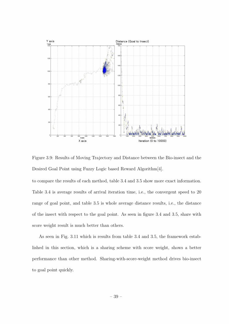
Figure 3.9: Results of Moving Trajectory and Distance between the Bio-insect and the
Desired Goal Point using Fuzzy Logic based Reward Algorithm[4].
to compare the results of each method, table 3.4 and 3.5 show more exact information.
Table 3.4 is average results of arrival iteration time, i.e., the convergent speed to 20
range of goal point, and table 3.5 is whole average distance results, i.e., the distance
of the insect with respect to the goal point. As seen in figure 3.4 and 3.5, share with
score weight result is much better than others.
As seen in Fig. 3.11 which is results from table 3.4 and 3.5, the framework estab-
lished in this section, which is a sharing scheme with score weight, shows a better
performance than other method. Sharing-with-score-weight method drives bio-insect
to goal point quickly.
– 39 –

Table 3.4: Average Results of Arrival Iteration for 5 Episodes [4].
Episode 1 2 3 4 5
Non Sharing 347.6 251.9 268.8 228.5 260.0
Sharing with Same Intensity 349.7 247 270.8 243.7 243.2
Sharing with Score Weight 340.0 271.6 220.7 225.4 208.7
Table 3.5: Average Results of Arrival Distance of the Bio-insect’s Trajectory for 5
Episodes [4].
Episode 1 2 3 4 5
Non Sharing 707.0 447.8 405.9 359.0 448.8
Sharing with Same Intensity 629.0 463.5 450 404.3 398.9
Sharing with Score Weight 632.9 490.8 405.4 426.5 364.2
– 40 –

3.7 Summary
On the basis of fuzzy logic, we developed fuzzy logic based reward and expertise
measurement system. Using this frame work, we could acquire a good performance
result in driving the bio-insect in spite of white Gaussian noise. However, this is just a
simulation result; real result shall be different in real experiment. Already mentioned
before, response of the bio-insect is not same in different time. So, it is not easy
work to drive the bio-insect in real experiment test. In our future research, we will
refine our fuzzy logic based reward and expertise measurement system for cooperative
reinforcement learning framework.
– 41 –

Figure 3.10: Distance Results between the desired goal point and the bio-insect for
5 episodes(500 iteration * 5)[4]. (a)Non sharing, (b)Sharing with same intensity and
(c)Sharing with score weight.
– 42 –

Figure 3.11: Average Results of Arrival Iteration (a) and Average Results of Arrival
Distance of the Bio-insect’s Trajectory for 5 Episodes (b) [4].
– 43 –

Chapter 4
Experimental Platform and Experiments
4.1 Introduction
In this chapter, we would like to announce that it is possible to influence the
movement of the bio-insect using our proposed actuation mechanism. When we try
to find interaction methods for a specific species of bio-insect, the biggest problem is
that we could not come up with any specific actuation method for the bio-insect. It
means that we exactly do not know what they want, think and react from what. After
a lot of experiments, finally, we empirically found an interaction method that uses
odor source from their habitat. In order to confirm our method, we have constructed
an experimental platform. The main goal of this chapter is to introduce the platform
built for the interaction. In section 2, we introduce our platform setup and interaction
method with simple experiment. In section 3, we explain experimental setup, and test
results. In Section 4, summary is given.
4.2 Hardware Platform Setup
For BRIDS, we use e-puck robot[21]. It is developed at swiss federal institute of
technology in Lausanne (EPFL) for education purpose. It has dsPIC 30f6014 microcon-
troller, 8 IR proximity sensor, 3D accelerometer, 3 microphones for finding direction,
– 44 –

VGA color camera, IR receiver for remote control and bluetooth module for wireless
connection. The robot can be programmed by open hardware that everyone can easily
use and develop it. Fig. 4.2 shows how equipment is connected.
Figure 4.1: E-Puck Robots[3].
For control of multiple e-puck robots, we use bluetooth access point that can allow
multiple serial connection. The e-puck robot is equipped with sercom protocol that can
make it easy to control via bluetooth serial connection. To find locations of each e-puck
robot and insect, we use image processing as shown in Fig. 4.3. This method can easily
obtain locations of bio-insect and mobile robots. It is, however, hard to distinguish
each e-puck robot’s location and heading angle. In order to solve this problem, we
propose landmarks composed of different colors and shapes. The landmarks will help
us to find a robot’s location and heading angle.
At first, we use color usb web camera for detecting 10 e-puck robots via landmarks
that are composed of two colors using black, red, yellow, baby blue and blue colors. In
order to detect location and heading angle of 10 landmarks, we use threshold method
– 45 –

Figure 4.2: Structure of the E-puck Robot[21].
and labeling algorithm. Threshold method can generate binary image, and labeling
algorithm can find each color block after threshold method. Using this manner, we can
find center position of each square color in landmark. And then, using two different
colors within defined range, we can find exact location and heading angle of each
landmarks. Following Fig. 4.5. shows first proposed landmarks and proposed program
detected location and heading angle of each e-puck robot.
Applying our hardware system in large space(2.2 meter by 1,8 meter), we use svs204
camera that has a resulution of 1024x768 pixel supplied 50fps and color vision with
– 46 –

Figure 4.3: Diagram of our Hardware Platform[3, 5]. This platform is composed of
bluetooth access point and main computer for control and image processing.
camera link interface. This camera link interface is connected to frame grabber in main
computer. In order to distribute each other, we use geometric model finder module
library in matrox image library(MIL) 9.0. This library help us detect not only each
e-puck robot but also a bio-insect from different shape. However, user should make
different shapes of landmarks to prevent wrong detection from similar shape. So, we
suggests 10 different landmarks shown in Fig. 4.6.
In order to confirm our hardware platform, we made simple autonomous algorithm
to display initials of our institute that are ’G’, ’I’, ’S’ and ’T’ by 10 epuck robots.
Each e-puck robot moves to desired locations for making formation of each initial
– 47 –

Figure 4.4: Bluetooth Access Point (left-side) and Camera (right-side)[5]. These are
installed the ceiling above our platform.
Figure 4.5: First proposed landmarks, which consisted of two different color mixture
(left-side), and program (right-side) to find heading angle and location of each e-puck
robot.
continuously. Following figure shows our real platform picture and formation images of
’G’, ’I’, ’S’ and ’T’. Using same manner, as mentioned before, this program can detect
– 48 –

Figure 4.6: 10 Proposed Landmarks for 10 e-puck robots to distribute each other are
suggested[5].
Figure 4.7: The GIST Formation Algorithm Software. After pushing ’Serial Connec-
tion’ and ’GRAB Thread’ button, this software displays location and heading angle of
each e-puck robot. And then, based on above results, this software send messages to
each robot to make formation of G, I, S and T continuously.
location and heading angle of the bio-insect as seen in fig. 4.9.
– 49 –

Figure 4.8: (a) and (b) - The platform for BRIDS[5]. (c), (d), (e) and (f) - Formation
of 10 e-puck robots. Each (c) , (d), (e) and (f) image displays G, I, S and T formation.
4.3 The bio-insect and artificial robot interaction: Experiment
4.3.1 The Model of Bio-insect and Experiments
Selection of a bio-insect is crucial in our experiment. First of all, the physical size
of the bio-insect should be same as our artificial robot because similar size is the most
important factor to interact each other. Also, we need to select a bio-insect that has a
physical strength, long life and good response from robot’s actuation. For this reason,
in related research, cockroaches are popularly used because of their strong physical
strength and long life in extreme environment. But cockroach is very fast; so, it is
– 50 –

Figure 4.9: The real image(left-side) is captured and detected(right-side) by our hard-
ware platform. Using same manner, this program can detect heading angle and location
of the bio-insect.
not easy to control it by artificial robot. We have tested various species of insects
to empirically select a bio-insect that is appropriate for our purpose. From a numer-
ous tests, we choose two insects. Each scientific name is Allomyrina dichotoma and
Serrognathus platymelus castanicolor Motschulsky. From simple test in our platform,
Allomyrina dichotoma as seen in Fig.4.11 is not good at working on flat place because
their habitat is tree and has short life time.
However, Serrognathus platymelus castanicolor Motschulsky as a scientific name,
normally called stag beetle, shows a good movement on flat space. Also it has two
years for average length of life and strong physical strength. A weak point of this
bio-insect are that it is nocturnal insect and not sensitive compared with cockroach.
Since it is not sensitive, it is hard to actuate it using artificial robots. Fig. 4.11 shows
a real image of our bio-insect chosen for our experiment.
– 51 –

Figure 4.10: Simple Experimental Test using Allomyrina Dichotoma ((a)-female and
(b)-male)
Figure 4.11: The Stag Beetles (female (left side) and male (right side)) are used in our
experiment[4, 6].
In order to find interaction methods between bio-insect and artificial robot, we have
tested various methods such as movement of our artificial robots, light, vibration, wind
and obstacle as see in Fig. 4.12. However, the bio-insect still has a problem of that
it is not active in our actuation normally. Usually, the reactions of the bio-insect are
– 52 –

contrary to our expectation. For example, we have expected that the insect escapes
from the robot when the robot approaches towards the insect. But, in actual cases,
the insect frequently approaches to the robot; even it tries to climb the robot. Thus,
we could not drive the insect towards a desired point. But, after lots of experimental
tests, fortunately, we have found a clue what bio-insect reacts to specific actuation.
As seen in Fig. 4.12, we attach a small piece of paper as an obstacle in working
range of left antenna side of the bio-insect. Thereafter, the bio-insect can feel that an
obstacle exists on the left side continuously, so, its moving trajectory looks like circle
path. In this simple experimental result, we figure it out that the bio-insect relies on
information from its antenna. Therefore, we focus on the antenna part.
4.3.2 Artificial Robot: An Agent
In order to do more advanced experiment, we revise e-puck robots for developing
our desired actuation as an artificial robot in BRIDS. In an e-puck robot part, first
of all, there are not enough ports to control other actuators and not enough voltage
to make strong performance of actuators. So, we add one more micro controller that
composes of 7.4v li-ion battery, voltage regulator for computer chips, micro controller,
max3232 to communicate between e-puck robot and another micro controller. And
then, we revise a program source of e-puck robot and make a new program source for
added micro controller. Fig. 4.13. shows real image of our artificial robot and structure
of the developed e-puck robot.
Applying to installed hardware platform introduced in section4.2, we can do ex-
– 53 –

Figure 4.12: The Bio-insects for Simple Experiment. Actuation Sources : (01 and 02) -
Light and Vibration, (03 and 04) - Obstacle[4, 6], (05) - Wind(using fans), (06) - Feed
for the Bio-insect
perimental test in remote area in order to prevent interference that occurs indirect
influence for movement of the bio-insect. In this advanced experiment, we focus on
how to stimulate the antenna of bio-insect effectively. Therefore, we use dual fan mo-
tors that make wind at different times and different direction respectively and air-pump
motors to spread hot, cold or specific odor sources. Sometimes, we use vibration motor
to get more maximized result when above explained actuators are executed.
As seen in Fig. 4.14, we have done different experimental tests using proposed
actuation methods. In case of 4.14-(a), we use dual fan motors to stimulate the
– 54 –

Figure 4.13: The Developed E-puck Robot(left-side) and Its Structure(right-side)[6].
antenna of bio-insect with different working period respectively. At first time in this
actuation, bio-insect shows reaction to avoid our artificial robot. Also, reactions from
bio-insect show more strongly when we did this actuation with vibration. However,
bio-insect did not keep reacting from continuous actuation. Sometimes, the bio-insect
approaches to the artificial robot after lots of experimental tests. As a result, we could
not bring out any possible result from this actuation.
In case of 4.14- (b), we use air-pump motor to spread hot or cold temperature of
air to the bio-insect using hot and cold water. Unfortunately, the bio-insect reacts hot
wind source at first, and then there are no more reactions. In this result, we can make
sure that temperature is not important factor.
In case of 4.14- (c), as seen in Fig. 4.15, we use air-pump motors to spread specific
odor sources such as jelly(feed) for insect, honey, juice, etc. We can find similar hard-
ware platform in [44] for communication of each artificial robots using pheromone. In
order to spread odor sources, it looks a suitable method. The differences between the
– 55 –

artificial robot(developed e-puck robot) and similar hardware platform in [44] are that
our artificial robot is much smaller than similar hardware robot and our robot spreads
odor source directly without fan for spreading deep odor source at the antenna working
range of the bio-insect. In this experimental result, the bio-insect dose not respond
any specific odor sources. Therefore, we could find any connection in this experimental
tests using the above actuations.
After experiments are finished at all times, the bio-insect tried to enter its habitat
in near area and looks more comfortable in its own habitat. From this phenomenon,
we guess that the bio-insect knows its own habitat odor. In order to confirm that
the bio-insect can detect own habitual odor source, we conduct experimental test in
case of Fig. 4.14-(c) using sawdust from its habitat. And then, finally, we could get
good result. When the artificial robot spreads odor source that consist of water and
sawdust from its habitat, the bio-insect follows the odor source to find location of the
habitat strongly. As a result, we can drag the bio-insect continuously using specific
odor source. As seen in Fig. 4.16, left side image is a real image of sawdust from its
habitat(right side).
Based on this result, finally, we empirically found an interaction method to achieve
our goal.
4.3.3 Experiment Setup
In order to evaluate our designed actuation method, we suggest new experiment
platform as seen in Fig. 4.17 and Fig. 4.18. Fig. 4.17 is a real image of designed platform
– 56 –

for our experiment and Fig. 4.18 is the diagram of our framework. Fig. 4.18 indicates
the size of the platform, initial position of agent, bio-insect and goal point and desired
path(dotted line) to reach goal point.
For a remote control of e-puck robots, we use Bluetooth communication channels as
introduced in [5]. In Fig. 4.3, a main computer transfers captured image from camera
for finding location and heading angle of each agent. Then, using the above information,
the artificial robots receive orders through Bluetooth access point from main computer
for achieving own goals. Here, we use a human operator as a substitution of robot
intelligence to control the artificial robot because this designed experiment only aims
to prove ability of proposed actuation method between the bio-insect and the artificial
robot. In this experiment, we use one artificial robot and two chosen bio-insect. Also,
in every experiment, we use same odor source, and the bio-insect and the artificial
robot start at initial position seen in Fig. 4.18.
4.3.4 Experiment Results
After a number of experiments, we have got 10 results from two candidates of
bio-insect. Each bio-insect has done five times of experiment. In this experiment
results, type of the candidate of bio-insects and lap time when the bio-insect moves
from the initial point to the desired goal point and percentage of completion rete in
every experiment are contained. Table 1 is the results of each experiment.
As seen in table 4.1, we have got 80 percentage of success rate. As a result, we can
make sure that this proposed actuation method is allowable to apply to our project of
– 57 –

Table 4.1: The Results from our Designed Experiment[6].
No. Type of Insect Lap Time Percentage of Completion Rate
01 1 2:08.27 100%
02 1 2:33.22 100%
03 2 3:25.00 100%
04 2 3:34.70 100%
05 2 4:11.53 100%
06 1 3:17.46 100%
07 1 2:55.72 100%
08 1 2:35.80 100%
09 2 − 30%
10 2 − 80%
BRIDS.
4.4 Summary
In this chapter, we have addressed the hardware platform and the dragging mech-
anism for an interaction between the stag beetle and the mobile robots. From our
designed experiment results, we can drag the bio-insect from initial point to goal point
with 80 percentage of success rate with our hardware system. However, our proposed
actuation method still has an uncertainty to drag the bio-insect. In our future work,
the uncertainty will be also learned by reinforcement learning algorithm. Also in a near
– 58 –

future, we would like to report an actual interaction between stag beetle and artificial
robots without any aid from human.
– 59 –

Figure 4.14: Advanced Experiment[6]. Using Dual Fan Motors-(a), Different Temper-
ature of Air-(b) and Different Odor Sources-(c).
– 60 –
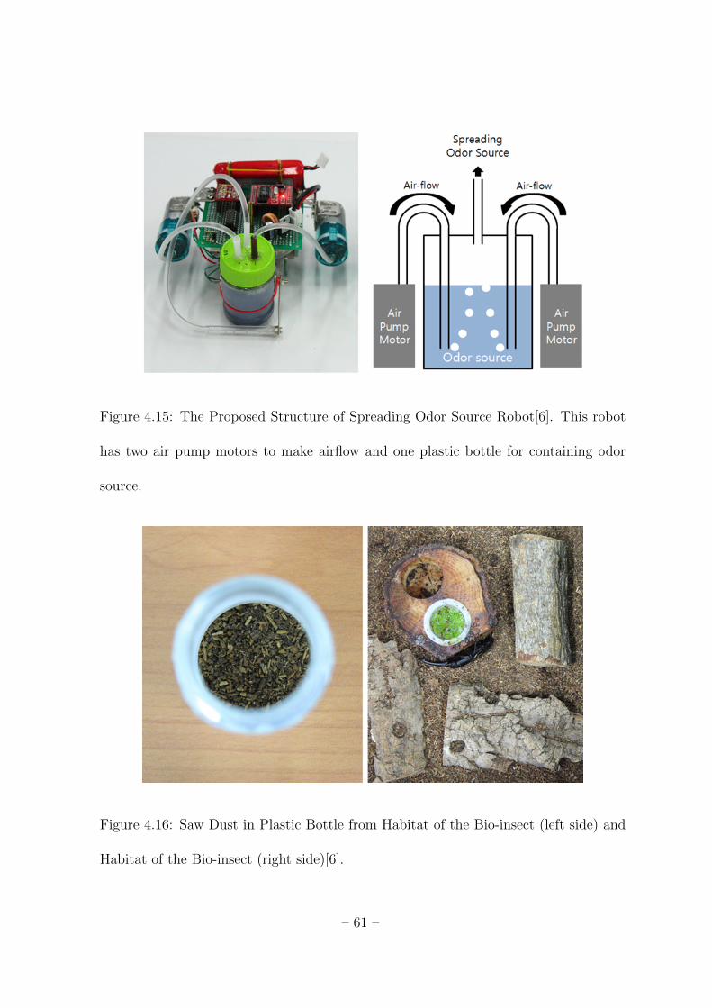
Figure 4.15: The Proposed Structure of Spreading Odor Source Robot[6]. This robot
has two air pump motors to make airflow and one plastic bottle for containing odor
source.
Figure 4.16: Saw Dust in Plastic Bottle from Habitat of the Bio-insect (left side) and
Habitat of the Bio-insect (right side)[6].
– 61 –
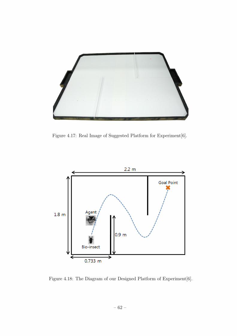
Figure 4.17: Real Image of Suggested Platform for Experiment[6].
Figure 4.18: The Diagram of our Designed Platform of Experiment[6].
– 62 –

Figure 4.19: The Program of E-puck Robots Controller. Using this program, human
operator can control motion, actuation of each developed e-puck robot via keyboard
interface of main computer system. Also this software displays heading angle and
location of the bio-insect and the developed e-puck robots in real time.
– 63 –

Figure 4.20: This is a real image taken from our designed experiment. The bio-insect
follows an artificial robot using its antenna from spreading odor source provided by the
artificial robot.
– 64 –

Chapter 5
Conclusion and Future Work
In this thesis, we have introduced our on-going research called BRIDS with some back-
ground knowledge, fuzzy logic based reward and expertise measurement system, hard-
ware platform and experiment results. Bio-insect and artificial robot interaction will
play an important part for improving the robot intelligence. In order to achieve the goal
of our research, this thesis suggests that the fuzzy logic based reward and expertise mea-
surement system employs fuzzy logic as a reward signal generator and score generator
for cooperative reinforcement learning. As a result, this thesis contribute to propose
new framework using AOE and fuzzy logic in cooperative reinforcement learning to
drive bio-insect towards a desired point based on fully autonomous coordination of
multiple mobile agents with good performance results in driving a bio-insect in spite of
white Gaussian noise. Meanwhile, finding acceptable actuation method was a difficult
problem in our research because they did not react from any stimulations by developed
e-puck robot. From various trial-errors, finally, we found acceptable actuation method
as introduced in section 4.3. Comparing with other researches introduced in related
works, this research topic can be considered as new because other researches did only
focus on the mechanism for finding interaction methods. In order to achieve the main
goal of BRIDS, in our future research, we will make developed actual actuation of a
bio-insect for real experiments and refine our algorithm of fuzzy logic based reward and
– 65 –

expertise measurement system for cooperative reinforcement learning framework, and
then, we would like to report results of real experiment.
– 66 –

References
1. G. Caprari, A. Colot, R. Siegwart, J. Halloy, and J.L. Deneubourg, “Building
mixed societies of animals and robots,” IEEE Robotics & Automation Magazine,
vol. 12, no. 2, pp. 58–65, 2005.
2. J. Halloy, G. Sempo, G. Caprari, C. Rivault, M. Asadpour, F. Tache, I. Said,
V. Durier, S. Canonge, JM Ame, et al., “Social integration of robots into groups
of cockroaches to control self-organized choices,” Science, vol. 318, no. 5853, pp.
1155, 2007.
3. Ji-Hwan Son and Hyo-Sung Ahn, “Cooperative Reinforcement Learning: Brief
Survey and Application to Bio-insect and Artificial Robot Interaction,” in
IEEE/ASME International Conference on Mechtronic and Embedded Systems and
Applications, 2008. MESA 2008, 2008, pp. 71–76.
4. Ji-Hwan Son and Hyo-Sung Ahn, “Fuzzy reward based cooperative reinforcement
learning for bio-insect and artificial robot interaction,” in 2009 IEEE/ASME Int.
Conf. Mechatronics and Embedded Systems and Applications, San diego, Califor-
nia, Aug. 2009.
5. Ji-Hwan Son and Hyo-Sung Ahn, “Design a hardware platform of BRIDS (Bio-
insect and artificial Robot Interaction based on Distributed Systems) for coop-
erative reinforcement learning experiment.,” in 2009 Korea Automatic Control
Conference (KACC), Busan, South Korea, Sep. 2009.
– 67 –

6. Ji-Hwan Son and Hyo-Sung Ahn, “Bio-insect and Artificial Robots Interaction: A
Dragging Mechanism and Experimental Results.,” in Proc. of the 2009 IEEE In-
ternational Symposium on Computational Intelligence in Robotics and Automation
(CIRA2009), Daejeon, Korea, Dec. 2009.
7. B.N. Araabi, S. Mastoureshgh, and M.N. Ahmadabadi, “A Study on Expertise of
Agents and Its Effects on Cooperative Q-Learning,” Systems, Man and Cybernet-
ics, Part B, IEEE Transactions on, vol. 37, no. 2, pp. 398–409, 2007.
8. MN Ahmadabadi and M. Asadpour, “Expertness based cooperative Q-learning,”
Systems, Man and Cybernetics, Part B, IEEE Transactions on, vol. 32, no. 1, pp.
66–76, 2002.
9. MN Ahmadabadi, A. Imanipour, BN Araabi, M. Asadpour, and R. Siegwart,
“Knowledge-based Extraction of Area of Expertise for Cooperation in Learning,”
Intelligent Robots and Systems, 2006 IEEE/RSJ International Conference on, pp.
3700–3705, 2006.
10. R. Holzer and I. Shimoyama, “Locomotion control of a Bio-robotic system via
electric stimulation Holzer Shimoyama,” in Proceedings of the 1997 IEEE/RSJ
International Conference on Intelligent Robots and Systems, IROS ’97, Grenoble,
France, 1997, vol. 3, pp. 1514–1519.
11. Yoshihiko Kuwanaa, Sumito Nagasawab, Isao Shimoyamab, and Ryohei Kanzakic,
“Synthesis of the pheromone - oriented behaviour of silkworm moths by a mobile
– 68 –

robot with moth antennae as pheromone sensors,” Biosensors and Bioelectronics,
vol. 14, pp. 195–202, 1999.
12. “http://www.conceptlab.com/roachbot/,” .
13. A.H. Purnamadjaja and R.A. Russell, “Guiding robots’ behaviors using
pheromone communication,” Autonomous Robots, vol. 23, no. 2, pp. 113–130,
2007.
14. W.J. Bell and E. Kramer, “Sex pheromone-stimulated orientation of the American
cockroach on a servosphere apparatus,” Journal of Chemical Ecology, vol. 6, no.
2, pp. 287–295, 1980.
15. K. Nishiyama, J. Okada, and Y. Toh, “Antennal and locomotor responses to
attractive and aversive odors in the searching cockroach,” Journal of Comparative
Physiology A: Neuroethology, Sensory, Neural, and Behavioral Physiology, vol.
193, no. 9, pp. 963–971, 2007.
16. R.S. Sutton and A.G. Barto, Reinforcement Learning: An Introduction, MIT
Press, 1998.
17. G. Erus and F. Polat, “A layered approach to learning coordination knowledge in
multiagent environments,” Applied Intelligence, vol. 27, no. 3, pp. 249–267, 2007.
18. Y. Wang and C.W. de Silva, “A machine-learning approach to multi-robot coor-
dination,” Engineering Applications of Artificial Intelligence, vol. 21, no. 3, pp.
470–484, 2008.
– 69 –

19. J.R. Kok and N. Vlassis, “Collaborative Multiagent Reinforcement Learning by
Payoff Propagation,” The Journal of Machine Learning Research, vol. 7, pp.
1789–1828, 2006.
20. C.W. Anderson and Z. Hong, “Reinforcement learning with modular neural net-
works for control,” IEEE International Workshop on Neural Networks Application
to Control and Image Processing, 1994.
21. “http://www.e-puck.org,” .
22. Raphael Jeanson, Colette Rivault, Jean-Louis Deneubourg, Stephane Blanco,
Richard Fournier, Christian Jost, and Guy Theraulaz, “Self-organised aggregation
in cockroaches,” Animal Behaviour, vol. 69, pp. 169–180, 2005.
23. G. Caprari, A. Colot, R. Siegwart, J. Halloy, and J.-L. Deneubourg, “Insbot :
Design of an Autonomous Moni Mobile Robot able to Interact with Cockroaches,”
in Proceedings of IEEE International Conference on Robotics and Automation.
ICRA’2004, New Orleans, 2004, pp. 2418–2423.
24. G. Kowadlo and R.A. Russell, “Robot odor localization: A taxonomy and survey,”
The International Journal of Robotics Research, vol. 27, no. 8, pp. 869, 2008.
25. MK Rust, T. Burk, and WJ Bell, “Pheromone-stimulated locomotory and orien-
tation responses in the American cockroach,” Anim. Behav, vol. 24, pp. 52–67,
1976.
– 70 –

26. EF Block et al., “Ethometric analysis of pheromone receptor function in cock-
roaches.,” Journal of insect physiology, vol. 20, no. 6, pp. 993, 1974.
27. LP Kaelbling, ML Littman, and AW Moore, “Reinforcement Learning: A Survey,”
Arxiv preprint cs.AI/9605103, 1996.
28. C.J.C.H. Watkins and P. Dayan, “Q-learning,” Machine Learning, vol. 8, no. 3,
pp. 279–292, 1992.
29. M Tan, “Multi-agent reinforcement learning : Independent vs. cooperative
agents,” in in ‘Proceedings, Tenth International Conference on Machine Learning
’, Amherst, 1993, vol. 1, pp. 330–337.
30. M.L. Littman, “Markov games as a framework for multi-agent reinforcement learn-
ing,” Proceedings of the Eleventh International Conference on Machine Learning,
vol. 157-163, 1994.
31. P. Tangamchit, J. Dolan, and P. Kosla, “The necessity of average rewards in
cooperative multirobot learning,” 2002.
32. Y. Wang and CW de Silva, “Multi-robot Box-pushing: Single-Agent Q-Learning
vs. Team Q-Learning,” Intelligent Robots and Systems, 2006 IEEE/RSJ Interna-
tional Conference on, pp. 3694–3699, 2006.
33. L. Panait and S. Luke, “Cooperative Multi-Agent Learning: The State of the
Art,” Autonomous Agents and Multi-Agent Systems, vol. 11, no. 3, pp. 387–434,
2005.
– 71 –

34. E. Courses and T. Surveys, “A Comprehensive Survey of Multiagent Reinforce-
ment Learning,” Systems, Man, and Cybernetics, Part C: Applications and Re-
views, IEEE Transactions on, vol. 38, no. 2, pp. 156–172, 2008.
35. L. Nunes and E. Oliveira, “Advice-Exchange Amongst Heterogeneous Learn-
ing Agents: Experiments in the Pursuit Domain,” poster abstract) Autonomous
Agents and Multiagent Systems (AAMAS03), 2003.
36. ME El-Telbany, AH Abdel-Wahab, and SI Shaheen, “Learning spatial and exper-
tise distribution coordination inmultiagent systems,” Circuits and Systems, 2001.
MWSCAS 2001. Proceedings of the 44th IEEE 2001 Midwest Symposium on, vol.
2, 2001.
37. P. Ritthipravat, T. Maneewarn, J. Wyatt, and D. Laowattana, “Comparison and
Analysis of Expertness Measure in Knowledge Sharing Among Robots,” LEC-
TURE NOTES IN COMPUTER SCIENCE, vol. 4031, pp. 60, 2006.
38. A. Nouri, A. Fazeli, and A. Rahimi Kian, “Designing a bidding-agent for elec-
tricity markets : a multi agent cooperative learning approach,” Accepted in the
International Federation of Automatic Control (IFAC), 2008.
39. R.A. Jacobs and M.I. Jordan, “A modular connectionist architecture for learning
piecewise control strategies,” Control Conference, American, vol. 28, 1982.
40. L.A. Zadeh, G.J. Klir, and B. Yuan, Fuzzy Sets, Fuzzy Logic, and Fuzzy Systems:
Selected Papers, World Scientific Pub Co Inc, 1996.
– 72 –

41. B.N. Araabi, S. Mastoureshgh, and M.N. Ahmadabadi, “A Study on Expertise of
Agents and Its Effects on Cooperative Q-Learning,” Systems, Man and Cybernet-
ics, Part B, IEEE Transactions on, vol. 37, no. 2, pp. 398–409, 2007.
42. MN Ahmadabadi and M. Asadpour, “Expertness based cooperative Q-learning,”
Systems, Man and Cybernetics, Part B, IEEE Transactions on, vol. 32, no. 1, pp.
66–76, 2002.
43. MN Ahmadabadi, A. Imanipour, BN Araabi, M. Asadpour, and R. Siegwart,
“Knowledge-based Extraction of Area of Expertise for Cooperation in Learning,”
Intelligent Robots and Systems, 2006 IEEE/RSJ International Conference on, pp.
3700–3705, 2006.
44. A. H. Purnamadjaja and R. A. Russell, “Guiding robots’ behaviors using
pheromone communication,” Auton Robot, vol. 23, pp. 113–130, 2007.
– 73 –