a study on bullock carts. part 1. engineering analysis of
TRANSCRIPT

Proc. Indian Acad. Sci., Vol. C 2, Part 4, Decembe~ 1979; pp. 435-449. ~)Printed in India.
A study on bullock carts. Part 1. Engineering analysis of the two-wheel bullock cart design
M R R A G H A V A N and H R N A G E N D R A Department of Mechanical Engineering, Indian Institute of Science, Bangalore 560 012
MS received 20 October 1979
Abstract. An engineering analysis of the design of two-wheel bullock carts has been carried out with the aid of a mathematical model. Non-dimensional expressions for the pull and the neck load have been developed. In the first instance, the cart is assumed to be cruising at constant velocity on a terrain with the effective coefficient of rolling friction varying over a wide range (0.001 to 0.5) and the gradient varying between + 0.2 to -- 0.2. Subsequently, the effect of inertia force due to an accele- ration parallel to the ground is studied. In the light of this analysis, two modifica- tions to the design of the cart have been proposed and the relative merits of the current designs and the proposed designs are discussed.
Keywords. Bullock carts; design; force analysis; performance; terrain; frictional resistance.
1. Introduction
There are over thirteen million animal-drawn carts in India, most o f which are two. wheel carts drawn by one or two bullocks or buffaloes. The design o f the conventional cart with two large steel-rimmed wooden wheels has been evolved empirically by the village artisans over the centuries. These carts ply on unprepared terrains in predominantly rural areas and prepared terrains (metalled/tarred/concrete roads) in and a round urban areas. To overcome the damage caused by these carts to prepared terrains, some of the two-wheeled carts have been fitted with steel axles and pneumatic wheels. The diameter o f the pneumatic wheels is obviously smaller than the diameter o f steel-rimmed wooden wheels o f conventional carts. No data is available on the elTeet o f a smaller wheel on the performance of the cart.
Recently, the basic mechanics of a two-wheel cart drawn by one or more animals has been analysed (Yajnik 1976). This analysis has been eordined to a cart cruising on a level horizontal road. I t has been observed that the opt imum resultant pull* PIJtV L (where PI~=(P2--~-kV~) 1/~) is virtually insensitive to variations of ~ over the range of 0"1 to 0.5 and of h/c over the range of 0.03 to 0.6. What is required, however, is a more comprehensive analysis which also includes the study of the effects o f gradient o f the terrain, variations in the horizontal and vertical disposition of the centroid o f the loaded cart, size of the wheels, etc., on the design and performance o f the cart. A comprehensive engineering analysis o f the two-wheel bullock cart design aimed at highlighting the weak features in the conventional
*A list of symbols appears at the end of the paper.
435
436 M.R Raghavan and H R Nagendra
design and identifying the areas where design improvements are most effective has, therefore, been carried out. The results of this analysis are presented in this part of the paper.*
2. Force analysis
2.1 ;Basic assumptions
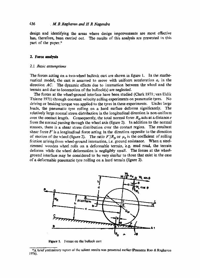
The forces acting on a two-wheel bullock cart are shown in figure 1. In the mathe- matical model, the cart is assumed to move with uniform acceleration ac in the direction AC. The dynamic effects due to interaction between the wheel and the terrain and due to locomotion of the bullock(s) are neglected.
The forces at the wheel-ground interface have been studied (Clark 1971 ; van Eldik Thieme 1971) through constant velocity rolling experiments on pneumatic tyres. No driving or braking torque was applied to the tyres in these experiments. Under large loads, the pneumatic tyre rolling on a hard surface deforms significantly. The relatively large normal stress distribution in the longitudinal direction is non-unifol m over the contact length. Consequently, the total normal force RD acts at a distance e from the normal passing through the wheel axis (figure 2). In addition to the normal stresses, there is a shear stress distribution over the contact region. The resultant shear force F' is a longitudinal force acting in the direction opposite to the direction of motion of the wheel (figure 2). The ratio F']R D or/~g is the eoefficient of rolling friction arising from wheel-ground interaction, i.e. ground resistance. When a steel- rimmed wooden wheel rolls on a deformable terrain, 'e.g. mud road, the terrain deforms while the wheel deformation is negligibly small. The forces at the wheel- ground interface may be considered to be very similar to those that exist in the ease of a deformable pneumatic tyre rolling on a hard terrain (figure 2).
d ~ - -Jt'wt c ~ e--
C L
Figure 1. Forces on the bullock cart
*A brief preliminary report of the salient results was presented earlier (Prasanna Rao & Raghavan 1976).

Engineering attalysis o f the two.wheel bullock cart design 437
Figure 2. Forces on the wheels
The yoke of a bullock cart generally rests on the neck(s) of the bullock(s) over a region just in front of the hump(s) of the bullock(s). The bullock pushes the yoke as it moves forward. The region of contact, i.e. the contact area, between the yoke and the neck of the bullock may be expected to vary as the bullock moves forward pushing the yoke.
In the present analysis, the frictional force between the neck(s) of the bullock(s) and the yoke is ignored. The force exerted by the bullock(s) on the yoke at time t is resolved into components: pull P and neck load WR, parallel and normal to the ground respectively. It is assumed that the location of the point of application of the force exerted by the bullock(s) on the yoke with respect to the ground is a constant, i.e., h and c are constants. The inclination of the platform surface, K H to the ground depends on the height h, the wheel diameter Dw, and the level of the platform surface from the ground. It is assumed that K H makes the same angle to the ground under all conditions of operation, i.e., on all terrains. The cart and the load on the cart are assumed to be symmetrical with respect to a plane normal to the wheel axis and located midway between the wheels. The forces exerted by the bullock(s) are also assumed to be symmetrical with respect to this vertical plane so that in the force analysis only the forces in this plane need be considered.
The coefficient of friction of the wheel bearings is/xb, while the coefficient of friction due to the ground resistance only is/%.
2.2 Effective resisting force
A free body diagram of the wheel assembly is given in figure 2. From this diagram the effective resisting force F is
F' -4- F n : [p, q- I~b (r/0.5 Dw)] RD : I �9 RD, (1)
so the effective coefficient of rolling friction/~ is given by
[g~ + i~v (r/0.5 D~,)]. (2)
2.3 Expressions for pull and neck load
In figure 3 is shown the free body diagram for the yoke-platform-axle assembly. From equilibrium considerations (figures 1 and 3)

438 M R Raghavan and H R Nagendra
WL sin 0 WL a
W L cos O
~ L P~ ~ . . . . .
i- Figure 3. Forces on the yoke-platform-axle assembly
P - - F - - WL sin O--(WL/g ) ac ~ 0 , (3)
Wz. cos 0-- WR--R D =0. (4)
Taking moments of all forces about the centre line of the axle E,
eb--WR c---WL cos O'a--W~ sin 0 (b+a)--(Wdg) ao (b+a) +p~R~,r =0, (5)
F= ~ i% = ~ (wL cos o ~ wR). (6)
Solving these equations for P, R o and W R and expressing all quantities in the non- dimensional form, we get
P / W L ~ i �9 [cos 0 ~ (WR/W~] -]- sin 0 + aJg, (7)
Rd wL =- cos o - - wd wL, (8)
WR/WL = cos 0 ~(b / c ) - - (a[c) + (P,b r/c)] - - (adg) (d/c) ~ (d/c) sin 0. (ga) 1 + (~ b/c) + O~b r/c)
The term (/~b tic) in the denominator can be neglected as it is very small compared to 1. ((Vb r[c) is about 0-003 for Vv of 0"2, axle diameter of 10 em and c of 380 cm). Also as the maximum contribution to the neck load (WR]Wt) due to the bearing friction torque is less than 0.003 the term ~b tic) in the numerator can also be neglected. So the final expression for the neck load is
WR/Wz ----- cos 0 [(/~ b/c) ~ (ale)] ~ (die) [sin 0 + (aJg)] (9) [I + ~ (b/c)]
This equation shows that the neck load can be reduced by designing the cart such that b is quite small. Also, when b is zero, the neck load is independent of/z.
As b ----- h~0"5Dw, (10)

Engineering analysis of the two-wheel bullock cart design 439
b can be quite small only if Dw~-2h. This implies that the wheel diameter should be large and close to twice the height of the neck of the bullock(s).
2.4 Variables and design parameters
The sensitivity of the various variables is studied and the performance of the cart under various operating conditions (terrain and load) is analysed. In the first instance, to simplify analysis, the cart is assumed to cruise at uniform velocity i.e. a c : 0. The expressions for the performance variables t'/WL and WR/W L, for a cart cruising at uniform velocity are from equations (7) and (9).
P/W L : / ~ (cos 0 - - Wn/WL) + sin 0, (ll)
Wn/WL ---- {cos 0 [/~ (b/c)-- (a/c)]-- (d/c) sin 0)][1 + I~ (b/c)], (12)
where 0 is positive if the gradient of the terrain is uphill, negative if the gradient is downhill.
2.4a. Range of variables and parameters In this analysis the diameter of the wheels D,~ is varied over a wide range: 30"5 em (12 in.) to 183 cm (72 in.). The size of the bullocks h enters indirectly into the analysis through b (equation (10)). b is varied over a wide range by keeping h constant at a typical value of 101"5 cm (40 in.) and varying Dw over a wide range. As all dimensions, b, a and d, are non-dimensionalised by dividing them by c, c can be kept constant at a typical value of 380 cm (150 in.). As P and W R are non-dimensionalised by expressing them in terms of W L, this analysis is valid for all loads on the cart.
From equation (2) it is seen that the contribution of the bearing friction to tz is only a small fraction (2r/Dw) of the bearing friction/xa. For example, with an axle of diameter of 50 mm (2 in.) the contribution of bearing friction to/~ is only 3 %, 8 ~o and 16% of/Xa for wheel diameters of 193 cm (72 in.), 61 cm (24 in.) and 30.5 em (12 in.) respectively.
/~ which varies with the type of bearing and the mode of lubrication lies in the range 0.001 to 0.2 (Shigley 1972). The coefficient of friction/% is estimated to be in the range 0"01 to 0"5 (Marks 1951). For a limited analysis of the bearing friction and wheel diameter on the performance of the car t , /~ is assumed to be equal to/% and they are varied over the range 0.001 to 0.2. For all other analysis,/~ is varied over the range 0.001 to 0-5. The horizontal shift a of the centre of gravity (CG) of the laden cart with respect to the vertical MN through the axle centre (figure 1) is varied over the range +30.5 (12 in.) to --30.5 cm (--12 in.). The normal distance d between the CG of the laden cart and the line of action of the pull LG is varied over a wide range: 0 to 91 cm (36 in.).
3. Performance of the two-wheel bullock cart
All computations have been carried out using a digital computer. of this analysis are presented in figures 4 and 5.
Typical results

440 M R Raghavan and H R Nagendra
0.4 i - . . . .
i -30.5r k ' ~ ) ~
0.2 d-O--x I I I 0,4
-0,~ ~ " -30.5 cm 112 in.)
h'101"Scm (40in: )
.o / / / ].., ~ / ' / 0w=30.5 cm_ (12 in.) I I b = 86cm (341in.) I
-Q3 =0.2 -0.1 0 - 0.1 0.2 '03 ton 0
Figure 4a. Effect of the gradient of the tcn'ain on pug P/Wz,. Whec] diameter = 30.5 cm (12 in.)
0.2 t-" d-91cm (36 in.) ~ = d= 91cm'(36 in.)
-0.1 / ' ~cm (2/+ in.) ~ J (12in.)
- 0 . 2 I I I i i -*'0.3 - 0 . 2 -0 .1 0 01 0.2 0.3
tan 0 Figure 4b. Effect of the gradient of the terrain on neck load WR/W L. Wheel diameter = 30.5 cm (12 in.)

Engineering analysis of the two-wheel bullock cart design 441
0.5
0,4
0.3
0.2
~'J 0.1
-0.1
-0.2
-0.3
. . . . ~ t W t ...... P t W L
. . . .
. . . . . . . . . . . 0.1
. . . . . . . . . . 02
/ h, '101.5 cm (40 in.)
/ C=,380 em (150in.) b - - l O cm ( 4 i n . )
a = O d = 9 1 c m ( 3 6 in.)
...... I . , I ,, 0 0.1 0.2 0.3 p
Figure 5. Effect of tL and tan 0 of the terrain on the performance. Wheel diameter = 183 cm (72 in.)
3.1 Effect of gradient on the performance
The effect of the gradient of the terrain on the performance of carts fitted with wheels of diameter 30.5 cm (12 in.), 61 era (24 in.) and 183 cm (72 in.) operating on a terrain with Fg=0.1 has been studied. In this study, t~ is also kept constant at 0.1 i.e., g,b =/% = 0. I. The other operational variables d and a defining the CG of the laden cart are varied to study their effects. Typical results are presented in figure 4 for cart with Dw=30.5 em (12 in.).
3.1a Pull This study shows that the magnitude of pull P/W L is significantly affected by the gradient of the terrain. A change in the gradient of +0-1 results in a change ofP[W L of about 4-0.1 (figure 4a). In a cart with balanced load (a=0) on a down- hill gradient of 0.11, the pull is zero. This means that, at higher downhill gradients, the yoke of the cart loses contact with the hump on the neck of the bullocks and the bullocks have to arch their necks upwards to apply a backward force to keep the cart stable. Or, a brake should be provided and applied to prevent the cart from becoming unstable.
On a ground with constant gradient, P[W L is rather insensitive to changes in the magnitude o f d. For example at tan 0=0.2, P/W L varies only by about 2 ~o, when d varies from 0 to 91 cm (36 in.). It is also seen that the shift (parallel to the ground)

442 M R Raghavan and H R Nagendra
of CG of the laden cart by 4-30.5 cm (4-12 in.) from the balanced position (a=0) causes only an insignificant change in P/WL. For example, on all gradients, a forward shift of a by 30.5 cm decreases P/Wr by only 0.008; a backward shift by 30.5 cm increases P/Wr by only 0.009.
This analysis shows that on any terrain, whatever be the diameter of the wheels, variations in the laden weight of the cart (WL) and in the location of the CG of the cart (defined by d and a) have an insignificant effect on the magnitude of the pull P/W~ to be exerted by the bullocks. If at all loads, i.e. at all d values, the minimum neck load requirement for negotiating the maximum uphill gradient expected is met by a suitable initial variation of a, the pull P/Wz, required for operation on a given terrain with constant/~g and gradient, is independent of the wheel diameter.
3.1b Neck load On a level road the neck load in a cart with balanced load (a=0) is a function of/~ and b/c only. Thus an increase in b, i.e. decrease in wheel diameter, D w with h constant, or increase in bullock neck height, h with Dw constant, increases the neck load almost linearly. For instance on a level ground with balanced load and/~g=/~b=0"l, the neck load is 0.026, 0-020, and 0.003 for carts with wheel diameters of 30.5 cm (12 in.), 61 cm (24 in.) and 183 cm (72 in.) respectively.
The effect of variation of the gradient of the terrain on the neck load is about the same for all wheel diameters. For instance, at d=91 cm (36 in.) the change in the neck load due to a variation of the gradient from --0"2 to +0.2 is about 0"092 for all wheel diameters (note that/~=/~b=0.1). In order to minimise the neck load the cart should be designed to have at full load as small a value of d as possible. This aspect is discussed in w 4.
Under identical conditions of operation--same d, tan 0, /~,/~b and a--the effect of change in a on the neck load, is about the same for all wheel diameters. Also, the neck load is quite sensitive to the horizontal shift of CG of the cart, i.e. change in a from the balanced position (a=O). For example, a rearward shift of CG by 30.5 cm (12 in.) from the balanced position results in a decrease of 0.079 in the neck load.
From this study, it is seen that the neck load can be kept at the minimum value required for effective traction by changing a by an amount dependent on the gradient of the terrain and the magnitude of d. This calls for a cart design by which when the cart is in motion there is a provision to manually shift the position of the CG of paxt of the cargo or the whole cargo to the desired extent. Such an arrangement, however, may decrease the simplicity and increase the cost of the cart.
3.2 Effect of frictional resistance of the terrain on the performance
In the previous section, the effect of gradient of the terrain on the performance was studied at constant ground friction and bearing friction i.e. p,g-----/~=0"l. In this section, the performance of the cart with wheel diameters of 30.5 cm (12 in.), 61 cm (24 in.) and 183 cm (72 in.) is studied when it moves over a terrain with effective coeffi- cient of rolling friction/~ varying over the range of 0.001 to 0.5; this study has been made for level terrain and terrains with gradients of 4-0.1 and 4-0.2. It is assumed that the load on the cart is maximum and balanced i.e. a = 0 and d is say 91 cm. The results of this study are presented in figure 5 for the cart with wheels of diameter of 183 cm (72 in.). A study of this figure and similarly figures for wheel diameters

Engineering analysis of the two-wheel bullock cart design 443
of 30.5 cm (12 in.) and 61 cm (24 in.) shows that in all cases the pull P/W L increases almost linearly with p. Further, under identical conditions of operation, i.e., same terrain gradient and V, the magnitude of the pull is about the same for all wheel diameters.
In the case of carts with large wheels, the effect of variation of/~ on the neck load is not significant on level terrain or sloping ground. For example, for a cart with wheels of diameter 183 cm (72 in.) on level ground, W~/W L is only 0 006 and 0.014 at P of 0.2 and 0.5 respectively. However, the variation of the neck load with V is significant in the case of carts with smaller wheels. For example, on a level ground with V of 0'5, the neck load for a cart with a wheel diameter o f 61 cm (24 in.) is about 550~ higher than that for a cart with 183 cm (72 in.) diameter wheels.
The variation in the neck load for a cart with 183 cm (72 in.) diameter wheels plying on a terrain with gradient varying between +0.2 to --0.2 and with V varying between 0.001 to 0.5 is 0.106. The corresponding value for the variation in the neck load for a cart with 61 cm (24 in.) diameter wheels is 0.174. Thus, from neck load considerations, one should prefer larger diameter wheels for the cart (the maximum diameter of the wheel is limited to 2 h). This is particularly so in the case of carts plying in rural areas where the maximum V is likely to be as high as 0.ft.
4. Design modification for improved performance
The analysis presented in the previous sections show that the diameter of the wheel Dw - - in terms of the design parameters b and the level of platform from the ground, h - - and the variable d, has a profound influence on the neck load of the bullocks. In this analysis, the level of the platform from the ground was taken to be constant for all
p G
/ / / / / / / / / / / / / ~ / / / / / / / / /
ptatform
((z) Ow
wn ow h
/ / / / / / / /~ / / / / / / /
(c) ~ o w (d) p G .
' 'f~f / / / / / / , t l / f f f / / f
Figure 6. v Carts of type A, type B and type C designs. (a) Type A design with large wheel (platform just above the axle). Co) Type B design with small wheel (elevated platform above the axle). (r Type C design with large wheel (platform underslung below the axle). (d)~Type A design with small wheel (platform just above the axle).

444 M R Raghavan and H R Nagendra
wheel diameters and set equal to that provided in 183 cm (72 in.) diameter wheel cart of current design (type A design in figure 6a). As mentioned already, this also re- presents the current practice in the design of a large number of carts with pneumatic smaller wheels (type B design in figure 6b). Two design modifications are proposed ---one for the large wheel cart (type C design in figure 6c) and the other for the small wheel cart (type A design in figure 6d), for reducing the neck load and enhancing the stability of the loaded cart. A comparative study of the performance of these four designs is presented below.
4.1 Smaller wheel cart of type A design
It is proposed to lower the platform of the smaller wheel cart to the same level above the axle as in the cart with large wheels (183 cm diameter wheel) (figure 6d) to effect a significant deercase in the magnitude of d corresponding particularly to full load on the cart. Such a decrease in d enhances the stability and produces a considerable decrease in the neck load. For instance, lowering the platform of a 61 em (24 in.) diameter wheel cart to the same level above the axle as in a 183 cm (72 in.) diameter wheel cart (type A design) brings down the CG of the fully loaded cart from say 91 cm (36 in.) to 30 cm (12 in.). The effect of this change in design on the neck load is shown in figure 7 for terrains with/~ varying from 0 to 0.2 and the gradient varying between 4- 0.2. As a minimum neck load, (WlJWt.)min, is necessary for effective traction particularly on terrains with low friction and high uphill gradient, it is assumed in the present study that this minimum value of neck load is provided in 61 cm (24 in.) diameter wheel carts of both type A and type B designs. The neck load in the cart of modified design (type A design) varies from (W~/Wt)ml ~ to [( WR/WL)~i ~ +0"067] as /a, varies from 0 to 0"2 and tart O varies from -t-0"2 to --0.2. The corresponding variation in the neck load in the cart of type B design, i.e. platform elevated to the same level as in 183 em (72 in.) diameter wheel cart, is 0.128. Thus, in the cart of modified design (type A design), the maximum neck load is consider- ably lower and the neck load variation over the minimum is lowered by 48 70.
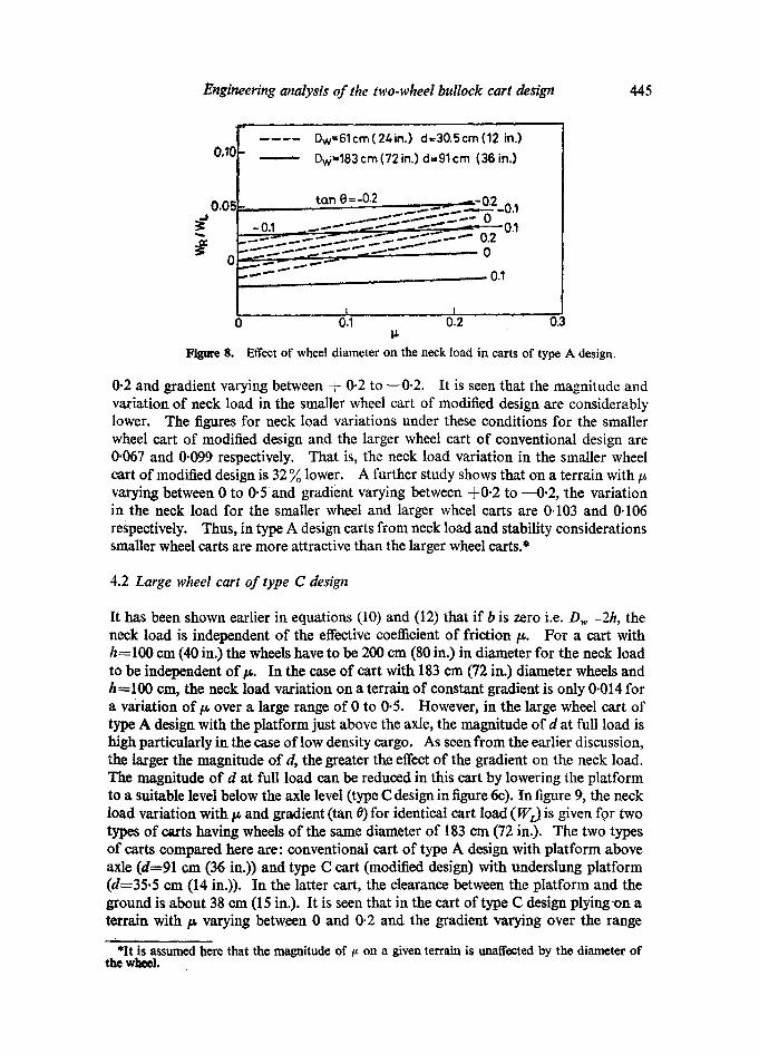
In figure 8 the neck load variation in 183 ern (72 in.) diameter wheel conventional cart (type A design) and 61 cm (24 in.)diameter wheel cart of modified design (type A design) is compared when operated in terrains with/~ varying over the range 0 to
0.10
~0.05
0
0.05
Figure 7.
Dw-61cm (24 in.) d = 91cm (36in.) type B design (figure 6hi d= 30.5cm (12 in.)type A design (figure 6d)
r . - ' - " - I i 0 0.1 0.2 0.3
Neck load in smaller wheel cart of type A andtype B designs.
Engineering analysis of the two-wheel bullock cart design 445
0.10 . . . . . .
o.os
- 0.1.
F i g u r e 8 .
Dw=61cm(24in.) d=30.5cm(12 in.)
Dw=183 cm (72 in.) d=91 cm (36 in.)
tan 0=-0.2 , ~..... ~._~S o 2_o.I
_ . ~ . . . ~ %. . . . - - - " _ s - - - 0.1
- - . . . - " - - ' ~ . . - " " ----.-" ~ 0
7" ! 1 I ..... 0 0.1 0 .2 0.3
tt
Effect of wheel diameter on the neck load in carts of type A design.
0.2 and gradient varying between q- 0.2 to --0.2. It is seen that the magnitude and variation of neck load in the smaller wheel cart of modified design are considerably lower. The figures for neck load variations under these conditions for the smaller wheel cart of modified design and the larger wheel cart of conventional design are 0.067 and 0.099 respectively. That is, the neck load variation in the smaller wheel cart of modified design is 32 ~ lower. A further study shows that on a terrain with/~ varying between 0 to 0.Sand gradient varying between -}-0.2 to ---0.2, the variation in the neck load for the smaller wheel and larger wheel carts are 0.103 and 0.106 respectively. Thus, in type A design carts from neck load and stability considerations smaller wheel carts are more attractive than the larger wheel carts.*
4.2 Large wheel cart of type C design
It has been shown earlier in equations (10) and (12) that if b is zero i.e. D,~ ~2h, the neck load is independent of the effective coefficient of friction/~. For a cart with h=100 cm (40 in.) the wheels have to be 200 cm (80 in.) in diameter for the neck load to be independent o fp . In the ease of cart with 183 cm (72 in.) diameter wheels and h=100 cm, the neck load variation on a terrain of constant gradient is only 0.014 for a variation of/~ over a large range of 0 to 0.5. However, in the large wheel cart of type A design with the platform just above the axle, the magnitude of d at full load is high particularly in the ease of low density cargo. As seen from the earlier discussion, the larger the magnitude of d, the greater the effect of the gradient on the neck load. The magnitude of d at full load can be reduced in this cart by lowering the platform to a suitable level below the axle level (type C design in figure 6e). In figure 9, the neck load variation with/~ and gradient (tan 0) for identical cart load (W z) is given for two types of carts having wheels of the same diameter of 183 em (72 in.). The two types of carts compared here are: conventional cart of type A design with platform above axle (d=91 cm (36 in.)) and type C cart (modified design) with underslung platform (d=35.5 can (14 in.)). In the latter cart, the clearance between the platform and the ground is about 38 em (15 in.). It is seen that in the cart of type C design plyingon a terrain with/~ varying between 0 and 0.2 and the gradient varying over the range
*It is assumed here that the magnitude of/~ on a given terrain is unaffected by the diameter of the wheel.

446 M R Raghavan and H R Nagendra
0.10
~-~ 0.05
-0.0~
Figure 9. designs.
Dw= 183cm (72 in,) - - - - - - - d= 35.5cm (14in.) type C cart . . . . . d - 91 cm ( 36 in.) type A ccirt
tan 0=-0,2
.-0.2 l i ; i H i . |
. . . . . .
, 0"2
w--- - - - -~ . .~ - -~ . - - - - - 1" o.2 '0.3
Necldoad in 183 r (72 in.) diameter wheel cart of tYPe A and typo C
+0.2 to --0"2, the neck load variation is only 0.041 as compared to 0"099 in the cart of type A design. Thus there is about 60 % reduction in the neck load variation in the cart of type C design. Further, the cart of type C design has enhanced stability and lower maximum neck load.
A comparative study of the performance of a 183 cm (72 in.) diameter wheel cart of type C design (d:35.5 cm (14 in.)) and a 61 cm (24 in.) diameter wheel cart of type A design (d=30.5 cm (12 in.)) plying with identical cart load (WL) over a terrain with p varying over a range: 0 to 0.5 and gradient varying between + 0.2 to - - 0.2 shows that the neck load variation under these conditions in the former cart is about 50 % lower. This study shows that from stability and minimum neck load considerations the large wheel cart of type C design is the most attractive.
5. Wheel bearings
It can be seen from equation (2) that the contribution of bearing friction to the effective coefficient of rolling friction,/~ is (r/0.5 Dw) times the coefficient of bearing friction/~b" For example with an axle of 5 cm diameter, the contribution of bearing friction to/~ is only 3 Yo and 8 % of/~b in carts with wheels of diameter 183 cm (72 in.) and 61 cm (24 in.) respectively. Further, as these carts operate at very low speeds, little advantage is gained by the use of costly anti-friction bearings (ball and roller bearings) in these carts. Sleeve bearings lubricated with suitable grease or viscous oil are satisfactory from both cart and performance considerations. However, these bearings should be provided with suitable thrust faces to take up the thrust loads arising from lateral motions of the loaded platform and the wheels.
6. Inertia loads
The analysis presented thus far is for carts cruising at constant velocity on terrains with varying/~ and gradient. Here, the effect of acceleration ac parallel to the ground, on the pull and the neck load is considered. Under all conditions of operation, the
Engineering analysis of the two-wheel bullock cart design 447
inertia force due to acceleration ac (equation (9)) reduces the neck load. As there has to be a minimum neck load for effective traction, the inertia force due to accoleration ac increases the magnitude of variation of the neck load on the bullocks. It also increases the maximum neck load. By decreasing d (equation (9)) under fully loaded conditions, the neck load component due to inertia force can be reduced. Smaller wheel carts of type A design and large wheel carts of type C design have significantly lower values of d at full load. Hence, in these carts the neck load compo- nent due to inertia force is considerably lower than in other cart designs.
From equation (7), it is seen that the component of pull due to inertia force is directly proportional to the acceleration ac.
7. Brakes
From the analysis presented above, it is noted that on downhill gradients greater than 0-1, the pull required is negative for all terrains with/~ less than about 0.1. Under these conditions of operation, some form of brake for the cart is essential to maintain stability of the cart and to avoid discomfort to the bullocks.
8. Conclusions
An engineering analysis of the design of two-wheel bullock carts has been carriod out with the aid of a mathematical model. Non-dimensional expressions for the pull and the neck load have been developed. In the first instance, the cart is assumed to be cruising at constant velocity on a terrain with the effective coefficient , of rolling friction/~ varying over a wide range: 0.001 to 0.5 and the gradient varying between + 0.2 to - - 0.2. Subsequently, the effect of inertia force due to an acceleration ac parallel to the ground, is studied. In the light of this analysis, two modifications to the design of the cart have been proposed and the relative merits of the current designs and the proposed designs are discussed. The broad conclusions of this study are:
(i) The pull P/Wt. is highly sensitive to the gradient of the terrain. Also it is a linear function of/x and a,.
(ii) On any terrain, variations in the laden weight (WL) of the cart and in the location of the CG of the laden cart has only an insignificant effect on the pull.
(iii) Under identical loading (WL, d and a constant), the effect of variation of the gradient of the terrain with constant t~ on the neck load is about the same for all wheel diameters,
(iv) The neck load is quite sensitive to the horizontal (parallel to the terrain) shift a of the CG of the laden cart from the balanced position a = 0. Under identical conditions of operation--the same gradient,/~, d and a--the effect of change in a on the neck load is about the same for all wheel diameters.
(v) For minimum neck load variation due to changes in/~ one should prefer larger diameter wheels for the cart with the maximum diameter of the wheels limited to 2h.
For the neck load variation due to the expected gradient change to be a minimum particularly at full load, d should be as small as possible.
(vi) Two new designs for the cart are proposed--one for the cart with larger wheels

448 M R Raghavan and H R Nagendra
(type C design) and the other for the cart with smaller wheels (type A design). A comparison of neck load variation in these carts with those in the conventional carts i.e., cart with large wheels (type A design) and the smaller wheel cart with elevated platform (type B design) shows that from neck load considerations the proposed type C cart design with relatively large size wheels (e.g. 183 cm (72 in.) diameter wheels) is most attractive. Also in type A design carts the smaller wheel carts (proposed design) are more attractive than the larger wheel conventional carts (in this analysis/~ is assumed to be independent of the wheel diameter).
(vii) For the wheels, sleeve bearings lubricated intermittently with suitable grease or viscous oil are satisfactory from both cost and performance considerations. How- ever these bearings call for a machined axle. Thrust faces should be provided in these bearings to take up thrust loads.
(viii) The inertia loads due to acceleration ac are relatively small in these slow speed vehicles. The neck load companent due to this inertia force is significantly low in the proposed cart designs--smaller wheel cart of type A design and the large wheel cart of type C design.
(ix) Some form of braking should be provided to ensure stability of the cart and to minimise discomfort to the bullocks while plying on terrains with down hill gradient and very low coefficient of rolling friction.
The work described was carried out under a project sponsored by the Tam Energy Research Institute, Bombay. The authors are grateful to Prof. A K N Reddy, Indian Institute of Science, for his inspiring interest in this work. Help given by Mr T S Shankar and Mr P Srikanth, former ME course students of the Department of Mechanical Engineering (I 976-78) in processing the results of this study is gratefully acknowledged.
List of symbols
a shift of centre of gravity of the cart D with respect to the normal to the ground passing through the point of contact Nand wheel centre E; cm (in.)
ac acceleration of cart in the direction of motion; cm/s ~ (in./s ~) b normal distance between the wheel centre and the line of action of pull P;
cm (in.) c normal distance between the wheel centre and the line of action of the neck
load WR; cm (in.) d normal distance between the centre of gravity of the cart D, and the line of
action of pull P; cm (in.) d' b + d Dw wheel diameter; cm (in.) e eccentricity of line of action of reaction Ra; cm (in.) F' frictional force due to ground resistance; kgf (lb) F ~ force at the wheel periphery to overcome bearing friction torque; kgf 0b) F (F' + Fn), effective resisting force; kgf 0b)

Engineering analysis of the two-wheel bullock cart design 449
g acceleration due to gravity; cm/s ~ (in./s s) h height of the point of application G of the resultant force due to the bullocks,
from the ground; cm (in.) P pull or component of the force exerted by the bullock(s) parallel to the
ground; kgf 0b) 2r diameter of wheel axle; cm (in.) R D normal reaction at the ground acting at an ecoentricity e; kgf (lb) W L total weight of the laden bullock cart; kgf(Ib) Ws neck load or component of the force exerted by the bullock(s) normal to the
ground ~0 coefficient of friction of the bearing /~g coefficient of rolling friction due to the ground resistance
effective coefficient of rolling friction 0 inclination of the ground to the true horizontal (degrees) tan 0 gradient.
References
Clark S K 1971 Monograph:of National Bureau of Standards, Washington, No. 122,p 455 Marks L S (ed.) 1951 Mechanical engineers handbook (New York: McGraw Hill), p. 222 Prasanna Rao D L & Raghavan M R 1975-76 Annual Report, Cell for Application of Science and
Technology to Rural Areas (ASTRA), Ilsc. Shigley J E 1972 Mechanical engineering design (Tokyo: McGraw Hill), pp. 386, 456 van Eldik Thieme H C A 1971 Monograph of National Bureau ;of Standards, Washington, No 122
p. 553 Yajnik K S 1976 Indian J. Technol. 14 472
Proc. C--3