a study on linear generator characteristics in free piston
TRANSCRIPT
International Journal of Transportation Engineering and Technology 2021; 7(3): 78-84
http://www.sciencepublishinggroup.com/j/ijtet
doi: 10.11648/j.ijtet.20210703.13
ISSN: 2575-1743 (Print); ISSN: 2575-1751 (Online)
A Study on Linear Generator Characteristics in Free Piston Engine
Ly Vinh Dat1, *
, Nguyen Thai Hoc2
1Faculty of Vehicle and Energy Engineering, Ho Chi Minh City University of Technology and Education, Ho Chi Minh City, Viet Nam 2Faculty of Automotive Engineering, Ho Chi Minh Industry and Trade College, Ho Chi Minh City, Viet Nam
Email address:
*Corresponding author
To cite this article: Ly Vinh Dat, Nguyen Thai Hoc. A Study on Linear Generator Characteristics in Free Piston Engine. International Journal of Transportation
Engineering and Technology. Special Issue: Transportation Engineering Technology and Education. Vol. 7, No. 3, 2021, pp. 78-84.
doi: 10.11648/j.ijtet.20210703.13
Received: August 21, 2021; Accepted: August 25, 2021; Published: August 31, 2021
Abstract: The linear generator (LG) is integrated into a system that called the free piston linear generator (FPLG). In recent
year, free piston engine that is studied by many researchers, has some advantages. Therefore, the application of the line generator
in free piston for converting the chemical energy to electrical energy that can be used for plug-in hybrids to extend the range of
operations as an alternative energy converter. Therefore, the optimizing of linear generator performance be able to significantly
reduce the vehicle's fuel consumption. The parameters in permanent magnet linear electric machine (PMLEM) are designed by
Maxwell software and the optimal parameters is carried out via the flux density. To achieve this goal, a linear generator in free
piston engine with a flat structure and quasi-Halbach array flux structure was proposed. The simulation of linear generator is
performed based on the speed ranges in the New European Driving Cycle (NEDC) for a mid-size car. In the study, a linear
electrical machine (LEM) is designed by Maxwell software with translator that has various diameters. The results show that the
suitable parameters for stator and rotor about 7.7 mm and 14 mm, respectively. Because the flux density for this design’s stator
and rotor yoke avoids saturation state and generates the highest electrical output compared to the other states. Besides, the paper
also examined the power output at different frequencies from 15 Hz to 50 Hz, corresponds to a velocity amplitude of 3.6 m/s to 12
m/s. The simulation result shows that the frequencies from 15Hz to 30 Hz with 4.8 m/s to 7.2 m/s (1200 rpm to 2100 rpm),
respectively meets engine speed operation ranges in hybrid vehicle and these frequencies produce the power output that increases
considerably about 7.5 kW at 30 Hz.
Keywords: Free-piston Linear Generator, Free Piston Engine, Maxwell, Permanent Magnet Generators, NEDC Driving Cycle
1. Introduction
Nowadays, many researchers always concentrate on the
drawbacks of conventional vehicle such as fossil fuel crisis
and global environment problems, their studies focus on the
converting the conventional fuel to alternative fuels that has
low emissions, high engine performance and efficiency.
Hybrid electric vehicle (HEV) that meets about the above
problems, it seems to be the best solution for this crisis in this
period, whereas the electric vehicle need considerably
improvement about battery life and cost. These advances in
battery technology will be solved in future but hybrid vehicle
combine between the conventional engine and electric motor
still the best solution on present transportation. Free piston
engine with linear generator has advantages in improving the
charge method in hybrid vehicle. Hence, the free piston linear
alternator (FPLA) which is regarded as one of the devices to
overcome the battery drawbacks about moving distance [1].
The FPLA, which combines the free piston internal
combustion engine (FPICE) and the linear alternator (LA), is
integrated the advantages of the two parts. This machine has
only one moving part and suffers less from the friction force
in operating. The piston motion is not constrained, therefore
some advance technologies as variable compression ratio
79 Ly Vinh Dat and Nguyen Thai Hoc: A Study on Linear Generator Characteristics in Free Piston Engine
(VCR), homogeneous charge compression ignition (HCCI)
and alternative fuel that are applied in free piston engine
easily. Consequently, free piston engine can improve engine
performance, efficiency and emission. As another main part
of FPLA, the LA is be directly utilized the linear piston force
without any need of the additional mechanical components
that are necessary in a rotary configuration. FPLA is thus an
effectively integrated energy conversion device.
Many institutions such as the German Aerospace Centre
(DLR), Toyota Central R & D Labs Inc. (Toyota), and the
Nanjing University of Science and Technology (NUST), have
carried out many studies on the single-cylinder FPLGs. Kock
et al. at DLR has developed a two-stroke single-cylinder
FPLG with the gas spring functioning as a rebounding device
[2–5]. The results showed that it could produce an electric
power output about 10 kW at 21 Hz. The output power could
be further improved up to 25 kW by increasing the motion
frequency up to 50 Hz.
The dual-piston type FPLG is a common configuration that
has been widely studied by many institutions such as the
Royal Institute of Technology (KTH), West Virginia
University (WVU), Shanghai Jiao Tong University (SJTU),
Newcastle University and the Beijing Institute of Technology
(BIT) [6–7]. Hansson et al. at KTH developed a dual-piston
FPLG prototype. The rated power of the generator was
produced about 29 kW. The system mean efficiency is 23%.
Their work mainly focused on the optimization design of the
linear electric machine specifically that is used in FPLG [8].
Shoukry et al. at WVU established a dual-piston two-stroke
prototype, which could produce a peak output electric power
of 316 W with a frequency of 23.1 Hz [9–11]. Xiao et al. at
SJTU have also studied the dual-piston FPLG. They also
developed a prototype and the motion characteristics of the
prototype were thoroughly investigated [12].
There are also a few studies on the opposed-piston FPLGs.
Van Blarigan et al. at Sandia National Laboratory (SNL)
developed an opposed-piston prototype. Their purpose
proposed to a FPLG design about 30 kW as the fuel cell for a
hybrid electric vehicle (HEV) [1, 13]. The synchronous
control of the opposed-piston FPLG is relatively more
difficult than the single-piston and dual-piston types.
The studies of different connective structures in PMLEM
can generally be classified according to geometrical structure
which includes the two main types: flat type and tubular type.
The main advantage of the tubular type is the net radial force
between the motor and stator is zero, and there is no terminal
winding. However, the magnetic rings and tubular stator are
difficult to produce, furthermore there are limited external
dimensions, the cross-sectional areas of the coil are limited
by the diameter of the magnetic rings in the PMLEM.
Although structure of a flat-type LEM is relatively simple, it
has some disadvantages such as the terminal coil. Nowadays,
the both types are investigated by researchers in the world. A
study conducted by Li et al. Of Shanghai Jiao Tong
University performed a simulation study for both flat and
tubular linear alternating generators [14]. The study used the
finite element models to simulate and compare the maximum
voltage, current density, specific power, and efficiency of two
AC generators. The work concluded that the flat type linear
generator has high efficiency, specific power, output voltage
and current compared with the tube type. Therefore, the flat
type linear generator is the most suitable choice for FPLE in
hybrid electric vehicle.
The magnetic flux structures in the Permanent Magnet
Linear Electric Machine (PMLEM) were proposed by Junnan
Wang, Nick J Baker [15], gave some main types of PMLEMs
under study for applications (Free-Piston Linear Generator,
FPLG). The study shown that the Transverse Flux Permanent
Magnet Linear Electric Machine (TFPMLEM) has the large
flux density, however, the power ratio is small due to the
large flux leakage and its complex structure makes high
production cost. Hence, it needs to be researched and
improved in future. For the Flux Switching Permanent
Magnet Linear Electric Machine (FSPMLEM) type, the study
found that it is not competitive to apply due to the leakage up
to 65% compared with TFPMLEM even it is improved about
tooth structure. Furthermore, the horizontal flux machine has
some advantages such as overall performance, power,
efficiency and small displacement mass. Compared with
SMPMLEM, both undergo a large moving mass which will
result in the low frequency of motion and slowly dynamic
response. Therefore, an SMPMLEM has the smallest moving
mass and high reliability due to their simple motor structure
and robustness and characteristic with high force density and
efficiency. SMPMLEM quasi-Halbach array shows the best
average performance in bearing capacity, moving mass
according to simulation studies, so it can improve the overall
performance of SMPMLEM [15], which is selected. for this
article.
2. Free- Piston Linear Generator System
From the previous studies, the authors find that the
single-cylinder FPLG, which is stable performance control
easily that comparing to the dual-piston and opposed-piston
engine types. Hence, the single-piston FPLG with gas spring
recovery device is considered as a promising design.
However, the long-term stable operation of the
single-cylinder FPLG remains a difficult problem. Besides
the lack of effective control strategies, improper system
design can also lead to unstable operation. To solve the above
difficulties, the German Aerospace Center (DLR) has
researched the design of the flat-type linear generator
coupled with the opposed-piston engine technology on the
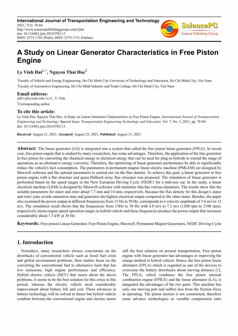
free piston [4]. Thanks to the integration of gas springs at the
rear of the combustion piston, the free-piston engine can
further reduce the length. Because of high efficiency and
reaching many advantages for dual-piston design, DLR is
developing the FPLG system with the central combustion
chamber (Figure 1). In this paper, the arrangement is also the
basis for the design of a linear generator on a free-piston
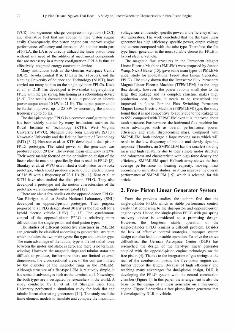
engine. Figure 2 describes a free piston linear generator that
is developed by DLR in vehicle.
International Journal of Transportation Engineering and Technology 2021; 7(3): 78-84 80
Figure 1. The DLR linear generator structure.
Figure 2. The linear generator layout on DLR vehicle.
3. Design of the Linear Electrical
Machine (LEM)
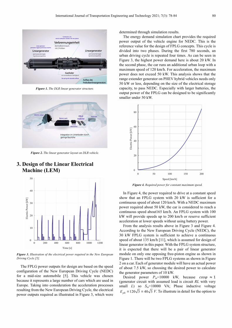
Figure 3. Illustration of the electrical power required in the New European
Driving Cycle [5].
The FPLG power outputs for design are based on the speed
configuration of the New European Driving Cycle (NEDC)
for a mid-size automobile [5]. This vehicle was chosen
because it represents a large number of cars which are used in
Europe. Taking into consideration the acceleration processes
resulting from the New European Driving Cycle, the electrical
power outputs required as illustrated in Figure 3, which were
determined through simulation results.
The energy demand simulation chart provides the required
power output of the vehicle engine for NEDC. This is the
reference value for the design of FPLG concepts. This cycle is
divided into two phases. During the first 780 seconds, an
urban driving cycle is repeated four times. As can be seen in
Figure 3, the highest power demand here is about 20 kW. In
the second phase, the car runs an additional urban loop with a
maximum speed of 120 km/h. For acceleration, the maximum
power does not exceed 50 kW. This analysis shows that the
range extender generator on PHEV hybrid vehicles needs only
50 kW or less, depending on the size of the electrical storage
capacity, to pass NEDC. Especially with larger batteries, the
output power of the FPLG can be designed to be significantly
smaller under 50 kW.
Figure 4. Required power for constant maximum speed.
In Figure 4, the power required to drive at a constant speed
show that an FPLG system with 20 kW is sufficient for a
continuous speed of about 120 km/h. With a NEDC maximum
power required about 50 kW, the car is considered to reach a
continuous speed about165 km/h. An FPLG system with 100
kW will provide speeds up to 200 km/h or reserve sufficient
acceleration at lower speeds without using battery power.
From the analysis results above in Figure 3 and Figure 4.
According to the New European Driving Cycle (NEDC), the
30 kW FPLG system is sufficient to achieve a continuous
speed of about 135 km/h [11], which is assumed for design of
linear generator in this paper. With the FPLG system structure,
it is expected that there will be a pair of linear generator
module on only one opposing free-piston engine as shown in
Figure 1. There will be two FPLG systems as shown in Figure
2 on a car. Each of generator module will have an actual power
of about 7.5 kW, so choosing the desired power to calculate
the generator parameters of 10 kW.
Desired power Pin=10000 kW, because ���� � 1
(generator circuit with assumed load is circuit RL with very
small L) so Sin=10000 VA; Phase inductive voltage
120 3 40 3phE = = V. To illustrate in detail for the option to

81 Ly Vinh Dat and Nguyen Thai Hoc: A Study on Linear Generator Characteristics in Free Piston Engine
set the input parameters for a linear generator, the paper
proposed the design of the 30 kW FPLG with stroke S=120
mm as an example based on the New European Driving Cycle
(NEDC) [5].
Part of the generator is used in 2D space modeling with
FEMM 4.2 software. In order to avoid excessive saturation of
the stationary (stator) and the moving part (rotor) their
permissible flux density has been less than 1.8 T for the stator
wall (due to the stator material Steel_1010) and to rotor is less
than 1.2 T (because the rotor material is Steel_1008). The
LEM structure is designed in Figure 5, Figure 6 and Figure 7
with design parameters are shown in Table 1.
Table 1. Linear Electrical Machine Parameters.
Stator core
Length � 396.002 mm
Width 80 mm
Slot opening � 22 mm
Tooth width �� 10.154 mm
Spring magnet thickness 8 mm
Stator yoke � 7.3 mm
Permissible flux stator yoke �� 1.8 T
Mean diameter of the windings �� 1.628 mm
Tooth high �� 33 mm
Translator core
Pole pitch �� 23 mm
Rotor yoke ��
Permissible flux rotor yoke ��� 1.2 T
Winding
Number of phases m 3
No. of poles p 12 Number of slots/ phase/ pole q 1/3
Turn number/ coil �� 50
Air gap flux density, �� 0.8 T
Airgap, g 2 mm
Slot filling factor ��� 0.6
Permanent Magnet
Magnet length �� 20.7 mm
Magnet thickness � 8 mm
Residual magnetic flux density �� 1.17 mm
Coercive magnetic field intensity �� 868000 A/m
Table 2. Parameter to stator and translator.
Stator 7.3 mm 7.3 mm 7.3 mm Translator 7.7 mm 14 mm 18 mm
�� 1.72 T 1.72 T 1.72 T
��� 2.02 T 1.19 T 0.89T
In the study, the permissible flux densities for stator yoke
are 1.8 T and rotor yoke is 1.2 T. Therefore, the suitable design
is performed with various translator diameters at 7.7 mm, 14
mm and 18 mm respectively. Whereas stator diameter is fixed
at 7.3 mm for all states due to space design limit. The results
are shown in Table 2. The suitable translator diameter is 14
mm, due to the flux density in permissible ranges. While the
flux density of rotor yoke is 2.02 T for 7.7 mm. This is larger
than permissible value (1.8T), hence the stator is saturated at
7.7 mm state. Otherwise, the flux densities for stator and
translator have values at 1.72 T and 0.89 T, respectively. These
flux densities have small value compared to the permissible
values, it leads to generate the small electrical output. Hence,
the stator wall size of 7.7 mm and the rotor wall size of 14 mm
is the best suitable flux density that has values in the
permissible region, this avoids saturation in the stator wall and
rotor with 1.72 1.8syB T T= < and 1.19 1.2
ryB T T= <
Figure 5. Flat projection of linear generator.
Figure 6. Linear Electrical Machine Model.
Figure 7. The vertical section of the linear generator.

International Journal of Transportation Engineering and Technology 2021; 7(3): 78-84 82
4. Simulation Results
The magnetic flux density B (Tesla), electromagnetic
density J (A/m2), magnetic field strength H (A/m) at 15 Hz
have described in a 3D model for stator (stationary part) and
translator (moving part) as Figure 8 and Figure 9.
At 15 Hz, the generator stator flux density has a maximum
value of max 1.7603 1.8SyB T T= < and the minimum value of
min 0.00227986SyB T= . With such flux density value, the
generator stator is not over saturated with flux.
Figure 8. The flux density B for stationary part (stator) of generator at 15 Hz.
At 15 Hz, the generator rotor flux density has a maximum
value of max 1.983 1.2SyB T T= < B, and a minimum value of
min 0.01499SyB T= . With such flux density value, the
generator rotor is not over saturated with flux.
Figure 9. Plot of flux density B for translator of generator at 15 Hz.
Linear generator modeling was performed mainly in Ansys
Maxwell software and used FEMM and Matlab Simulink
software for supporting. Simulation results show that the
generator is not excessively saturated with flux at the core of
the static part (stator) and the dynamic part (rotor). The
simulation results about current, voltage at 15 Hz with 3.6 m/s,
respectively are described in Figure 10, Figure 11 and Figure
12. The result show that the maximum current is Iph=2.3 A,
while the maximum phase voltage magnitude is Eph=26 V and
the maximum polarity voltage is Vout=14.7 V at 15 Hz.
Figure 10. 3-phase current for linear generator at 15 Hz.
Figure 11. 3-phase voltage for linear generator at 15 Hz.

83 Ly Vinh Dat and Nguyen Thai Hoc: A Study on Linear Generator Characteristics in Free Piston Engine
Figure 12. Voltage for linear generator load at 15 Hz.
The other frequencies are practiced similar to these above
processes. The power of the linear generator at the various
frequencies from 15 Hz to 50 Hz, corresponds to a velocity
amplitude of 3.6 m/s to 12 m/s, shown in Table 3.
Table 3. Pin input power and generator Pout output power at frequencies
from 15 Hz to 50 Hz.
Frequencies f (Hz) Power Input Pin (W) Power Output Pout (W)
15 179.4 452.5
20 452.5 227
25 607.1 311.4
30 754 375.4
35 802.3 407
40 835.6 418.7
45 872.3 435.6
50 897.6 448.8
The magnitude of the output power and input power from
15 Hz to 50 Hz of the linear generator is shown in Figure 13.
Figure 13. Generator input and output power chart from 15 Hz to 50 Hz.
The input and output power are proportional to the
frequency and speed of the linear generator. When the motor
frequency is 30 Hz, the speed is 7.2 m/s, the input power and
output power increase slightly.
The generator efficiency varies from 50% to 55%, as the
frequency increases the efficiency of the generator also
increases. However, the value of Pin and Pout have a bigger
difference.
When the engine has speed amplitude Vrm=7.2 m/s (f=30 Hz)
or more, the generator produces Pout≈7.5 kW output power or
more in accordance with the requirements for use in hybrid
vehicles. When the linear generator reaches velocity
amplitude Vrm=7.2 m/s (f=30 Hz) the power of the generator
starts to increase slightly, so increasing the motor speed is too
high. The free-piston engine of FPLG system with speed range
from 4.8 m/s to 7.2 m/s or 1200 rpm to 2100 rpm (or
frequencies from 15 Hz to 30 Hz) is suitable for linear
generators that used on electric hybrid vehicle.
5. Conclusions
In the FPLG, the LEM design is one of the crucial
techniques for achieving high power density and stable
performance. LEM permanent magnets are the most suitable
solution for FPLG. The use of a linear generator with a
Halbach PM array is an effective way to reduce the mass of
motion and improve the efficiency of the dynamic response.
The flat type construction is more suitable for space limited
applications. Motion magnet LEMs are preferred for high
power FPLGs because of their high reliability compared to
motion coils. Both TFPMLEM and FSPMLEM can achieve
high power density but have low power factor and complex
structure, and the combination of both PMLEM may be a
promising option that needs further research.
The mechanical parameters for the linear generator
simulation are based on those of the German Space
Agency-DLR free piston engine with a piston stroke of 120
mm and reaching 50 Hz. The feasibility of the linear generator
in the paper is shown by the numerical simulation results on
Ansys Maxwell software from 15 Hz to 50 Hz with a velocity
range from 3.6 m/s to 12 m/s (1200 rpm to 2100 rpm).
Simulation results show that the generator is not excessively
saturated with flux at the core of the static part (stator) and the
dynamic part (rotor). For free-piston engine frequencies from
15 Hz to 50 Hz, the amperage of linear generators ranges from
2.3 A to 3.4 A; Phase voltage ranges from 26 V to 88 V; Pole
voltage ranges from 14.7 V to 40 V; Input power ranges from
179.4 W to 897.6 W; Output power ranges from 101.4 W to
448.8 W; and the efficiency ranges from 50% to 56.5%.
The input and output power are proportional to the
frequency and speed of the linear generator. When the motor
frequency is 30 Hz at the speed is 7.2 m/s, the input power and
output power increase slightly.
Acknowledgements
The authors would like to acknowledge Ho Chi Minh City

International Journal of Transportation Engineering and Technology 2021; 7(3): 78-84 84
University of Technology and Education' help which has
sponsored this research.
References
[1] P. Van Blarigan, “Free-Piston Engine,” In Proceedings of the 2009 DOE Vehicle Technologies Program Annual Merit Review, Arlington, VA, USA; pp. 1–17, 2009.
[2] F. Rinderknecht and F. A. Kock, “High Efficient Energy Converter for a Hybrid Vehicle Concept-Gas Spring Focused,” In Proceedings of the Symposium EVER12, Monte Carlo, Monaco, 22–24 March 2012.
[3] F. Kock, J. Haag, H. E. Friedrich, “The Free Piston Linear Generator-Development of an Innovative, Compact, Highly Efficient Range-Extender Module,” SAE Tech. Pap, 2013.
[4] C. Ferrari, H. E. Friedrich, “Development of a Free-Piston Linear Generator for use in an Extended-Range Electric Vehicle,” In Proceedings of the EVS26 International Battery, Hybrid and Fuel Cell Electric Vehicle Symposium, Los Angeles, CA, USA, 6–9 May, 2012.
[5] S. Schneider, F. Rinderknecht and H. E. Friedrich, “Design of Future Concepts and Variants of The Free Piston Linear Generator,” In Proceedings of the 2014 Ninth International Conference on Ecological Vehicles and Renewable Energies (EVER), Monte Carlo, Monaco, pp. 1–8, 25–27 March 2014.
[6] P. Zheng, A. Chen, P. Thelin, W. M. Arshad and C. Sadarangani, “Research on a Tubular Longitudinal Flux PM Linear Generator Used for Free-Piston Energy Converter,” IEEE Trans. Magn. Vol 43, pp. 447–449, 2007.
[7] J. Hansson, M. Leksell, “Performance of a Series Hybrid Electric Vehicle with a Free-Piston Energy Converter,” In Proceedings of the Vehicle Power and Propulsion Conference, Windsor, UK, pp. 1–6,.6–8 September 2006.
[8] J. Hansson, M. Leksell, F. Carlsson and C. Sadarangani, “Operational Strategies for a Free Piston Energy Converter”. In Proceedings of the Fifth International Symposium on Linear Drives for Industry Applications, Kobe-Awaji, Japan, 25–28 September 2005.
[9] P. Khayyer, P. Famouri, “Application of Two Fuel Cells in Hybrid Electric Vehicles,” SAE Tech. Pap. 2008.
[10] E. F. Shoukry, “Numerical Simulation for Parametric Study of a Two-Stroke Compression Ignition Direct Injection Linear Engine,” West Virginia University: Morgantown, WV, USA, 2003.
[11] E. Shoukry, S. Taylor, N. Clark and P. Famouri, “Numerical Simulation for Parametric Study of a Two-Stroke Direct Injection Linear Engine,” SAE Tech. Pap. 2002.
[12] J. Xiao, Q. Li, Z. Huang, “Motion Characteristic of a Free Piston Linear Engine,” Appl. Energy, Vol 87, pp. 1288–1294, 2010.
[13] T. Johnson, “Free-Piston Engine,” Sandia National Laboratories: Albuquerque, NM, USA, 2012.
[14] Q. F. Li, J. Xiao, Z. Huang, “Flat-type Permanent Magnet Linear alternator: a suitable device for a free piston linear alternator,” J. Zhejiang Univ.-Sci. A (Appl. Phys. Eng.) Vol 10, pp. 345–352, doi: 10.1631/jzus.a0820224, 2009.
[15] J. Wang, N. J. Baker, “Comparison of Flux Switching and Modulated Pole Linear Machines for use with a Free Piston,” In Proceedings of the IEEE International Electric Machines & Drives Conference (IEMDC), Coeur d’Alene, ID, USA, pp. 642–648, 10–13 May 2015.
Biography
Ly Vinh Dat (Viet Nam). He hold associate
Professor in 2017, and graduated PhD of
Mechanical and Electrical Engineering in
2013, National Taipei University of
Technology, Taipei, Taiwan. Research
interests: Efficiency improvement in SI and
CI engines, Intake and exhaust systems,
Electro-magnetic valve train, improving of
efficiency, fuel consumption and emission in
internal combustion engines, etc. Work
experiences: has taught as a lecturer at Faculty of Vehicle and
Energy Engineering, University of Technology and Education Ho
Chi Minh City, Vietnam, since 2003.
Nguyen Thai Hoc - was born in Vietnam. He
received his master degree in Vehicle
Engineering from Ho Chi Minh City
University of Technical Education
(HCMUTE) in 2021. He is a lecturer at
faculty of Automotive Engineering at Ho Chi
Minh Industry and Trade College. His
research interests include engine advance
technologies, engine management systems,
hybrid and electric vehicle.