a study on the nonmetallic inclusion motions in a swirling … · a study on the nonmetallic...
TRANSCRIPT

A Study on the Nonmetallic Inclusion Motionsin a Swirling Flow Submerged Entry Nozzlein a New Cylindrical Tundish Design
PEIYUAN NI, MIKAEL ERSSON, LAGE TORD INGEMAR JONSSON,and PAR GORAN JONSSON
Different sizes and shapes of nonmetallic inclusions in a swirling flow submerged entry nozzle(SEN) placed in a new tundish design were investigated by using a Lagrangian particle trackingscheme. The results show that inclusions in the current cylindrical tundish have difficultiesremaining in the top tundish region, since a strong rotational steel flow exists in this region. Thishigh rotational flow of 0.7 m/s provides the required momentum for the formation of a strongswirling flow inside the SEN. The results show that inclusions larger than 40 lm were found todeposit to a smaller extent on the SEN wall compared to smaller inclusions. The reason is thatthese large inclusions have Separation number values larger than 1. Thus, the swirling flowcauses these large size inclusions to move toward the SEN center. For the nonsphericalinclusions, large size inclusions were found to be deposited on the SEN wall to a larger extent,compared to spherical inclusions. More specifically, the difference of the deposited inclusionnumber is around 27 pct. Overall, it was found that the swirling flow contains three regions,namely, the isotropic core region, the anisotropic turbulence region and the near-wall region.Therefore, anisotropic turbulent fluctuations should be taken into account when the inclusionmotion was tracked in this complex flow. In addition, many inclusions were found to deposit atthe SEN inlet region. The plotted velocity distribution shows that the inlet flow is very chaotic.A high turbulent kinetic energy value of around 0.08 m2/s2 exists in this region, and arecirculating flow was also found here. These flow characteristics are harmful since they increasethe inclusion transport toward the wall. Therefore, a new design of the SEN inlet should bedeveloped in the future, with the aim to modify the inlet flow so that the inclusion deposition isreduced.
https://doi.org/10.1007/s11663-017-1162-y� The Author(s) 2017. This article is an open access publication
I. INTRODUCTION
NONMETALLIC inclusions are of highest impor-tance during steel production. This is due to the fact thatthey not only can affect the steel product quality in anegative manner but can also cause an interruption ofthe continuous casting process by clogging the tundishsubmerged entry nozzle (SEN). To summarize,
inclusions induce product or production problems,which are closely related to the inclusion transport insteel flows during the continuous casting process.Therefore, the understanding of inclusion behaviors insteel flows is important to optimize the productionprocess and to improve the product quality.In the tundish and mold, steelmakers have the last
chance to remove nonmetallic inclusions in order tomake steel clean. The removal of inclusions in thetundish can reduce the number concentration of inclu-sions in the molten steel, which is expected to reduce theclogging rate in the tundish SEN. In the past, a largenumber of numerical simulation studies have investi-gated the behaviors of inclusions during the steelcontinuous casting process.[1–25] For the inclusionmotion in tundish, studies have been carried out toinvestigate the inclusion removal under the effects ofvarious factors such as flow control devices, tundishgeometries, gas bubbling rates, and inclusion sizes.[1–8]
After inclusions move from the tundish into the SEN,
PEIYUANNI is with the Key Laboratory of Ecological Metallurgyof Multi-metal Intergrown Ores of Education Ministry, School ofMetallurgy, Northeastern University, 110819 Shenyang, China andalso with the Department of Materials Science and Engineering, KTHRoyal Institute of Technology, 100 44 Stockholm, Sweden. Contactemail: [email protected] MIKAEL ERSSON, LAGE TORD INGE-MAR JONSSON, and PAR GORAN JONSSON are with theDepartment of Materials Science and Engineering, KTH RoyalInstitute of Technology.
Manuscript submitted July 21, 2017.Article published online December 29, 2017.
METALLURGICAL AND MATERIALS TRANSACTIONS B VOLUME 49B, APRIL 2018—723
their deposition on the SEN wall can lead to nozzleclogging. In order to understand the deposition locationand mechanism, computational fluid dynamics (CFD)studies have been carried out to investigate the inclusiontransport in turbulent steel flows and its deposition onthe SEN walls.[9–17]
Deposition rates of inclusions on the SEN wall werepredicted by using an Eulerian deposition model, whichconsidered the transport of inclusions in the turbulentflow boundary layer as well as the turbophoresiseffect.[16,17] Finally, inclusions move into the moldaccompanying steel flows, where the solidification ofmolten steel happens. The concerns about inclusions inmolds include its removal to the top mold slag and itscapture by the solidifying front. These concerns havebeen investigated in many CFD studies focusing onSEN port designs, SEN submerged depths, argoninjection, electromagnetic braking, and so on.[18–25]
Among them, the particle-capture model developed byThomas et al.[25] gives a good contribution to describethe particle capture behavior at the solidifying front,since it represents a good physical framework byconsidering the local force balances.
In recent years, the use of a swirling flow or arotational flow during steel castings has received a lot ofattention. Two methods to realize a swirling flow orrotational flow during the steel casting have beenintensively studied, namely, the swirling flow SENmethod[26–34] and the mold-electromagnetic stirring(MEMS) method.[35–38] When using a swirling flowSEN, the penetration depth of the SEN outlet flow inmold was found to decrease.[28] The stability of the steelflow in the mold was enhanced and the defects on theslab surface were effectively reduced.[31] Furthermore,the swirling flow in the SEN was found to effectivelyreduce the clogging tendency of the SEN port.[31] This isdue to the fact that the nozzle port flow becomeshomogenous and stable when a swirling flow exists inthe SEN. In addition, a swirling flow produced by therotary MEMS method in an industry application wasfound to effectively reduce the central cracks, centralporosities, and shrinkages.[36] Therefore, the use of aswirling flow or a rotational flow during metal castingsis becoming an important way to produce high-qualitysteels. However, previous studies[26–38] of swirling flowsduring steel castings mainly focused only on theinfluence on the steel flow itself. Furthermore, previousstudies[1–25] focusing on the inclusion behavior in steelflows have mostly been carried out for conventionalcontinuous casting processes, where no rotational steelflow phenomena exist in the horizontal cross sections ofthe SEN or the mold. In a swirling flow, the motions ofthe light nonmetallic inclusions are expected to bedifferent from those in a conventional casting flow. Thisis due to the centripetal separation effect, which causeslight inclusions, with a density smaller than molten steel,to move toward the swirling flow center. This maychange the transport and deposition behavior of non-metallic inclusions.
As mentioned earlier, the inclusion motion is impor-tant for both the steel quality and the steel productionprocess. Therefore, it is interesting and meaningful to
investigate the influence of a swirling steel flow on theinclusion behaviors during casting operations. Previousstudies on the behaviors of nonmetallic inclusions inswirling steel flows are limited. Yang et al.[32,33] inves-tigated the nonmetallic inclusion motion in a swirlingflow, which was obtained by applying electromagneticstirring outside the SEN. Ni et al.[34] investigated thebehaviors of Al2O3 and Ce2O3 inclusions in a swirlingflow SEN obtained from a new tundish design. It wasfound that large size light nonmetallic inclusions movetoward the swirling flow center, due to the centripetalseparation effect.[34] Hou et al.[39] investigated theinclusion removal in a swirling flow chamber, whichwas installed at the tundish inlet region. It was foundthat this design is suitable to use for the removal of20-lm inclusions but not large size inclusions, com-pared to a conventional tundish.[39] However, thesesimulation studies were carried out using swirling flowfields, which were solved by using the k-e typeturbulence model in combination with a standard wallfunction.[32–34,39] Thereafter, a Lagrangian particletracking scheme was used to describe the inclusionmotion in the solved flow fields. Therefore, theisotropic turbulent fluctuations were assumed and theturbulent boundary layer was not resolved. However,in a swirling flow, a large velocity gradient rangingfrom the swirling flow center to the wall normallyexists in the radial direction. Anisotropic fluctuationsmay exist in such a flow situation. This is especiallytrue in the turbulent boundary layer. Furthermore,turbophoresis has been found to be of importancewhen considering the particle transport in turbulentboundary layer.[16,17] However, these aspects have beenignored in previous studies.[32–34,39] In the absence ofresolving the turbulence boundary layer, inclusionsmay simply fly to the wall once they reach thewall-adjacent grid cell. Therefore, this cannot give agood prediction on the inclusion transport toward awall when particle depositions in turbulent flows occur.This has been confirmed by results in the literature.[40]
In addition, both the flow field and the inclusionmotion have previously not been validated by exper-iments.[32–34] Also, a recent study shows that the k-etype turbulent models sometimes underpredict theswirling flow intensity.[41] Therefore, studies are stillrequired to give a good prediction on the transport ofinclusions, toward the swirling flow center and towardthe wall, in a swirling flow or a rotational steel flow.In this article, the behaviors of nonmetallic inclusions
in the swirling steel flow in a new cylindrical tundishdesign were investigated based on both numericalsimulations and water model experiments. The steelflow field has been solved by using a Reynolds stressturbulent model (RSM), combined with a Stress-Omegasubmodel, to account for the possible anisotropicfluctuations in a swirling flow. Furthermore, the numer-ical model was validated by particle image velocimetrymeasurements in water model experiments.[42] In addi-tion, the turbulent boundary layer was also resolved.Specifically, the y+ value of the first grid layer wassmaller than 1, and 21 layers of grid cells were used atthe near-wall region to account for the turbophoresis
724—VOLUME 49B, APRIL 2018 METALLURGICAL AND MATERIALS TRANSACTIONS B

effect for particle transport in the turbulent boundarylayer. This should improve the accuracy of the predic-tions of the particle transport toward a wall comparedto the previously presented results.[32–34] Differentshapes and sizes of Al2O3 inclusions were tracked usinga Lagrangian scheme that accounted for the inertialforce, drag force, gravity and buoyancy, lift force,pressure gradient force, and virtual mass force acting oneach individual inclusion. Also, a statistical analysis wascarried out to investigate the number of inclusions,released from the location close to the SEN inlet, thattouch the SEN wall in different regions along thevertical direction of the SEN. In addition, the separationphenomena, due to the centripetal effect, of the lightnonmetallic inclusions in the swirling steel flow werestudied. Furthermore, a dimensionless number, theSeparation number, was for the first time proposed inthis article. This number can be used to define thepossibility of different inclusions to be separated in aswirling flow.
II. MODEL DESCRIPTION
The three-dimensional mathematical model of thenew cylindrical tundish is made in a Cartesiancoordinate system. The steel flow field in the newtundish has previously been solved by using theRSM[43–45] combined with the Stress-Omega[45,46] sub-model. Furthermore, the predictions have been vali-dated by water model experiments.[42] The inlet steelflow rate is 5.0 m3/h. The steel density and itsmolecular viscosity are 7000 kg/m3 and 0.0064 kg/(ms), respectively. Molten steel flows into the cylindricaltundish from its tangential inlet. This leads to arotational steel flow inside the cylindrical tundish.After the rotational steel flow moves into the SEN, aswirling flow can be produced due to the rotationalflow potential. In the current article, the previouslysolved steel flow field was used to study the behaviorsof inclusions in the tundish and SEN.
The model geometry, the injection locations ofinclusions, and the divided SEN wall regions are shownin Figure 1. The other model information can be foundin the literature[42] and is not repeated here. Theinclusion tracking was done using the discrete phasemodel, which is available in the commercial softwareANSYS FLUENT 17.0�. The density of the Al2O3
inclusions was assumed to be 3500 kg/m3, based on thedata from Reference 47.
A. Inclusion Tracking Assumption and BoundaryCondition
(1) Inclusions escaped from the domain when they ex-ited from the SEN outlet.
(2) Inclusions were assumed to stick on the SEN wallonce they touched it; a ‘‘reflect’’ boundary conditionwas used for the other tundish walls.
(3) Interactions between inclusions were not considered.
(4) A one-way coupling between steel and inclusionswas used; i.e., the influence that inclusions have onthe steel flow was not considered.
B. Lagrangian Particle Tracking Model
The locations of inclusions were obtained by solvingthe following equation:
up ¼ dxpdt
½1�
where xp is the inclusion position and up is the inclu-sion velocity. The inclusion velocity was obtained bysolving the following momentum equation:
dupdt
¼u� up� �
srþ g 1� qf
qp
!
þ 1
2
qfqp
upru� dupdt
� �
þ qfqp
upruþ 2Kv12qfSij
qpdp SlkSklð Þ14
u� up� �
½2�
where the first term on the right-hand side is the dragforce per unit inclusion mass, the second term on theright-hand side is the force per unit inclusion mass dueto gravity and buoyancy, the third term on the right-hand side is the virtual mass force per unit inclusionmass, and the fourth term on the right-hand side is thepressure gradient force per unit inclusion mass. Thefifth term on the right-hand side is the Saffman’s liftforce.[48,49] Furthermore, sr is the particle relaxation
Inlet flow
Location 1 of Inclusion release
Region 2Region 3Region 4Region 5Region 6Region 7Region 8Region 9Region 10Region 11Region 12Region 13Region 14Region 15Region 16
15 R
egio
ns ×
0.04
m0.
05
Location 2 of Inclusion release
Z=0
Line 1
Loca
tions
for t
he a
vera
geof
m
axim
um ta
ngen
tial v
eloc
ity
0.15
m0.
10.
15m
0.15
m0.
10m
Outlet 0.04m
0.20
0.18
(Unit: m)
Z
XRegion 1
0.20
0.10
0.20
0.40
Square Inlet 0.035×0.035
Fig. 1—Geometry of the new tundish design and the location of dif-ferent SEN wall regions.
METALLURGICAL AND MATERIALS TRANSACTIONS B VOLUME 49B, APRIL 2018—725

time and Red is the relative Reynolds number. Theyare expressed by the following equations:
sr ¼qpd
2p
18l24
CDRed½3�
Red ¼qfdp u� up
�� ��
l½4�
where u is the continuous-phase velocity; l is themolecular viscosity of the fluid; v is the kinematic vis-cosity of the fluid; dp is the diameter of an inclusion;and qf and qp are the densities of the fluid and theinclusion, respectively. Furthermore, Sij and Slk arethe deformation tensor, and K is a constant, which isequal to 2.59.[49]
For spherical particles, the drag coefficient,CD, fromMorsi and Alexander[50] was used.
CD ¼
24:0=Red Red<0:122:73Red
þ 0:0903Re2
d
þ 3:69 0:1<Red � 1:0
29:1667Red
� 3:8889Re2
d
þ 1:222 1:0<Red � 10
46:5Red
� 116:67Re2
d
þ 0:6167 10<Red � 100
98:33Red
� 2778Re2
d
þ 0:3634 100<Red � 1000
148:62Red
� 47500Re2
d
þ 0:357 1000<Red � 5000
� 490:546Red
þ 578700Re2
d
þ 0:46 5000<Red � 10000
� 1662:5Red
þ 5416700Re2
d
þ 0:5191 10000<Red � 50000
8>>>>>>>>>>>>>>>>>><
>>>>>>>>>>>>>>>>>>:
½5�For nonspherical particles, the following relationships
for the drag coefficient suggested by Haider andLevenspiel[51] were used:
CD ¼ 24
Resph1þ b1Re
b2sph
� �þ b3Resphb4 þ Resph
½6�
where
b1 ¼ expð2:3288� 6:4581/þ 2:4486/2Þ
b2 ¼ 0:0964þ 0:5565/
b3 ¼ expð4:905� 13:8944/þ 18:4222/2 � 10:2599/3Þ
b4 ¼ expð1:4681þ 12:2584/� 20:7322/2 þ 15:8855/3Þ
The shape factor, /, is defined as follows:
/ ¼ Ssph
S½7�
where Ssph is the surface area of a sphere having thesame volume as the particle and S is the actual surfacearea of the particle. Resph is the relative Reynoldsnumber based on the diameter of a sphere having thesame volume as the particle, dsph. This dsph value wasused to calculate the particle mass and drag force.In a swirling flow, nonmetallic inclusions, which are
lighter than molten steel, may move toward the swirlingflow center, due to the centripetal effect. In an inertialframe of reference, e.g., the Cartesian coordinate systemused in this model, the centrifugal force does not trulyexist. Calculations can be performed by using Newton’slaws of motion and by considering the real existingforces, e.g., the drag force, lift force, virtual mass force,gravity force, buoyancy force, and pressure gradientforce. The centripetal effect for the separation of lightinclusions should mainly come from the pressure gradi-ent force, which has been included in the particlemomentum equation shown in Eq. [2].
C. Particle Stochastic Turbulence Model
In order to simulate the effect of the turbulentfluctuations on the inclusion motion, a stochasticturbulent model can be used. This approach was basedon the eddy lifetime,[52] which spawned the eddy-inter-action models in which the fluid velocities (eddies) areassumed to be stochastic quantities. These remainconstant for the lifetime of the eddy or, if shorter, thetransit time of the particle through the eddy.[53] There-fore, the continuous-phase velocity can be expressed byusing the following equation:
½8�
where �u and are the continuous-phase averagedvelocity and the fluctuating component, respectively. �uis obtained by solving the Eulerian equations for thecontinuous phase. Moreover, is calculated by thefollowing equation:
½9�
where f is a zero mean with a unit variance and is a
normally distributed random number. is the
root-mean-square local fluctuation velocity in the idirection, which directly can be solved by using theRSM. Therefore, anisotropic turbulent fluctuationswere taken into account in this article.
III. RESULTS
A. Inclusion Motion in the Tundish
In order to know the inclusion motion in the upperpart of the tundish, inclusions of different sizes andshapes were released from location 1 (shown in Fig-ure 1) near the tundish inlet. Figure 2 shows theinclusion trajectories in the cylindrical tundish. Here,
726—VOLUME 49B, APRIL 2018 METALLURGICAL AND MATERIALS TRANSACTIONS B

the stochastic turbulence model was not used to avoidthe uncertainty induced by the turbulent fluctuations.Therefore, only the mean flow velocity was used whentracking the inclusion motion. This will give a generalunderstanding of the motion behaviors of inclusions ofdifferent sizes and shapes in the tundish. It can be seenfrom Figure 2 that all the investigated inclusions, withthe sizes of 1, 10, and 100 lm, are not able to stay at thetop of the cylindrical tundish. This means that thebuoyancy force was not high enough to keep theseinclusions in the upper region. This is due to a large steelflow velocity at the top tundish region, with the value ofaround 0.7 m/s,[42] which also leads to a strong mixing.This strong rotational flow provides the requiredmomentum for an intensive swirling flow later in theSEN. In addition, the residence time of inclusions in thecylindrical tundish increases with an increased inclusionsize. This is because the buoyancy force always causesinclusions to float upward, where larger size inclusionsobtain a larger buoyancy effect. This buoyancy reducestheir velocity moving from the top of the tundish to thetundish bottom and, thus, increases their residence time.For inclusions with different shapes, a similar trajectory
for 1-lm-size inclusions was observed, as shown inFigures 2(a) and (b). This means that the influence ofthe shape factor on their motion is small in the currentinvestigation. However, for large inclusions, it wasfound that nonspherical inclusions have a longer resi-dence time in the tundish compared to the sphericalinclusions. In addition, 100-lm inclusions of bothspherical and nonspherical types were found to stayinside the SEN center after that they entered the SENregion. This is due to the centripetal separation effect,which causes inclusions to move toward the center, anddue to the buoyancy effect, which makes them moveupward.In order to know the inclusion motion in the swirling
flow SEN, glass-bubble particles were released at loca-tion 2 (shown in Figure 1) near the SEN inlet. Theseparticles have a density smaller than the density ofwater, with a value in the range of around 700 to 1000kg/m3. Furthermore, the particle sizes are in the range ofaround 50 to 1000 lm.Figure 3 shows the particle location in the SEN
obtained from the water model experiments and fromthe simulation. It can be seen that the inclusion locations
Diameter 1 µm 10 µm 100 µm
(a) Sphere
(b)
Non-sphere
=0.7
Time, s Time, s Time, s
Time, s Time, s Time, s
Fig. 2—Inclusion motions in the cylindrical tundish: (a) sphere inclusion and (b) nonsphere inclusion.
METALLURGICAL AND MATERIALS TRANSACTIONS B VOLUME 49B, APRIL 2018—727

predicted by the numerical simulations are similar to theobservations from the water model experiments. Specif-ically, Figure 3(a) shows that particles move toward theSEN center in the water flow. Thereafter, they stay inthe center region of the SEN, where they rotate togetherwith the swirling water flow. Figure 3(b) shows that100-lm Al2O3 inclusions move toward the nozzle centerand that they are located at the upper part of the SEN.This is due to the centripetal effect, the buoyancy effect,and the upward steel flow in the center of the swirlingflow SEN, as shown in a previous study.[42] In thesimulations, Al2O3 inclusions have half the density ofmolten steel. However, in reality, it is difficult to findparticles with a density that is just half of water’sdensity. Normally, the density of particles used in watermodel experiments is close to but slightly smaller thanthe density of water, and it is in a range of values ratherthan having a certain value. Also, it is difficult to findparticles with one particular size. They normally onlycan be found in a size range. In addition, it is difficult toobserve very small particles, such as 100-lm inclusionsused in the simulations. According to the inclusiontrajectory similarities between particles in water modelsand particles in simulations, the particle sizes in thewater models and in the simulations should follow therelationship in Eq. [10][54]:
rwrs
¼
ffiffiffiffiffiffiffiffiffiffiffiffiffiffiffiffiffiffiffiffiffi1� qp
ql
� �
s
1� qpql
� �
w
vuuut k�14 ½10�
where rw and rs are the particle radius in the watermodel experiments and in the simulations, respectively.Furthermore, qp and ql are the densities of particles
and the liquid, respectively. The parameter k is thescale factor, which has a value of 1 in this article.
Table I shows the required sizes of different densitiesof glass-bubble particles used in water model experi-ments in order to simulate 100-lm Al2O3 inclusions,
which were tracked in the simulations in Figure 3(b). Itcan be seen that the required particle size in the watermodel to simulate 100-lm inclusions in the steel flows isin the range of particle sizes (50 to 1000 lm) that wereused in the current water model experiments. Thismeans that the current water model can qualitativelyillustrate the behavior of particles in the swirling flowand the results can be used to validate the numericalmodel predictions.
B. Statistical Study on Inclusion Motion in the SEN
In order to understand the inclusion behaviors in theswirling flow SEN, 1200 inclusions were released fromlocation 2 (shown in Figure 1) to investigate theirbehaviors in the SEN. A doubling of the releasedinclusion number did not give an improved statisticalresult. Here, a particle was assumed to deposit on thewall once it touched the wall. The number of inclusionsthat deposited on the SEN wall is shown in Figure 4. Itcan be seen that the number of deposited inclusions ofboth spherical and nonspherical shapes shows initially aslight increase with an increased inclusion size. There-after, the results indicate a sharp decrease for theinclusion sizes ranging from 20 to 40 lm. For inclusionswith sizes smaller than 20 lm, spherical inclusions havea bit larger deposited number compared to nonsphericalinclusions. However, for large inclusions, a greaternumber of nonspherical inclusions were predicted totouch the wall, compared to the spherical inclusions.For example, the deposited number of 40-lm
time (s)
(a) (b)
(Unit: m)
Z
X
Release Location 2
Fig. 3—(a) Particle location in the water model experiment and (b) trajectories of 100-lm inclusion in the numerical simulation.
Table I. Required Size of Different Particle Densities in
Water Models to Simulate 100-lm Inclusions Present in SteelFlows
Density (kg/m3) 0.7 0.8 0.9 0.99Diameter (lm) 129 158 224 707
728—VOLUME 49B, APRIL 2018 METALLURGICAL AND MATERIALS TRANSACTIONS B

nonspherical inclusions was found to be 27 pct higherthan that of spherical inclusions.
Figure 5 shows the number of inclusions thatdeposited on the SEN wall in different regions. Thelocations of the different regions are shown in Figure 1.It can be seen that the numbers of different sizeinclusions, which are smaller than 20 lm, that depositedon the SEN wall show a similar distribution trend alongthe different SEN regions. In addition, for small sizeinclusions, the inclusion shape seems to have almost no,or only a slight, influence on their deposition behavior.In region 16, the largest number of deposited inclusionswas found among all the regions. This region is locatedat the SEN inlet, which is closest to the inclusion releaselocation. When inclusions move downward with thesteel flow from region 16, the number of depositedinclusions shows a slight decrease. This may be due tothe fact that the number concentration of inclusionsclose to the wall in the steel flow decreased, sinceinclusions may have deposited on the wall in the upperflow regions of the SEN. For large inclusions, e.g.,40-lm inclusions, both spherical and nonsphericalinclusions show a large difference with respect to thedeposited number distribution along different SENregions, compared to the small inclusions. From region10 to region 15, a much smaller number of largeinclusions were predicted to touch the wall. More
specifically, approximately one fifth of the number ofdeposited small size inclusions deposited on the wall.However, in the regions close to the SEN outlet, thenumber of large size inclusions that deposited on theSEN wall increased to a similar level as that of small sizeinclusions. Furthermore, a 40 pct larger number of40-lm nonspherical inclusions were found to touch thewall compared to spherical inclusions. However, for100-lm inclusions, both the spherical and nonsphericalinclusions were found not to touch the SEN wall, exceptin region 16. This is due to the centripetal effect, whichcan be seen from the inclusion trajectories inFigure 3(b).In order to understand why large amounts of inclu-
sion are deposited in region 16, the steel flow in this SENregion is plotted in Figure 6. Figure 6(a) shows the steelflow paths from four points. The locations of thesepoints are shown in Figure 6(b). The steel flow has twovelocity components, as shown in Figure 6(a). Onevelocity component is directed toward the SEN center(this is the common situation in a conventional tundish),and another velocity component is directed in thetangential direction due to the rotational steel flow inthe tundish. Due to the tangential flow component, thesteel flow has difficulty reaching the center of the SEN.Instead, it tends to flow toward the SEN wall. After itgets close to the wall, its flow direction changes, due tothe curved SEN wall, to form a swirl flow. In addition,steel flow paths from different points are different. Thisillustrates that a nonuniform SEN inlet flow exists. Thiscan be seen clearly from Figures 6(c) through (f), wherethe tangential velocities of the steel flow in differentcross sections of the SEN in region 16 are plotted. Thesteel flow field is not uniform and the maximum velocityis larger than 5 m/s. A swirling flow is developing in thisregion and it is uneven and chaotic. As the steel flowsdownward in the SEN, the maximum steel flow velocitydecreases and the velocity distribution in the crosssection tends to become a developed flow. This meansthat the swirling flow is under development in region 16(shown in Figure 1).Figure 7 shows the steel flow properties in the middle
XZ plane of the SEN. It can be seen that a recirculating
0100200300400500600700800900
1000
1 µm 10 µm 20 µm 40 µm 100 µm
Dep
osite
d In
clus
ion
Num
ber
Inclusion Diameter, µm
Sphere
Non-Sphere
27 %
Fig. 4—Deposited number of different sizes and shapes of inclusions.
0
20
40
60
80
100
120
140
160
180
200
1 2 3 4 5 6 7 8 9 10 11 12 13 14 15 16
Dep
osite
d In
clus
ion
Num
ber
Wall regions
Sphere 1 micro Sphere 10 microSphere 20 micro Sphere 40 microSphere 100 micro Non-Sphere 1 microNon-Sphere 10 micro Non-Sphere 20 microNon-Sphere 40 micro Non-Sphere 100 micro
40%
SEN Inlet SEN Outlet
Fig. 5—Number of inclusions deposited on the SEN wall at different regions (the regions are shown in Fig. 1).
METALLURGICAL AND MATERIALS TRANSACTIONS B VOLUME 49B, APRIL 2018—729
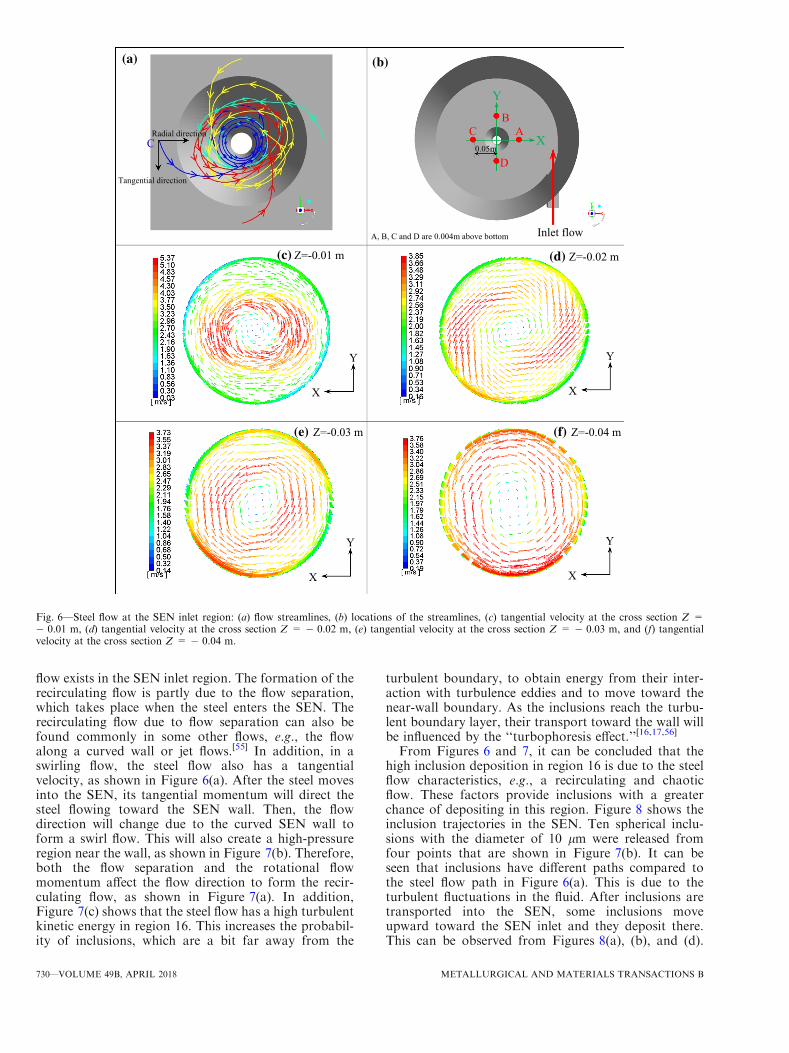
flow exists in the SEN inlet region. The formation of therecirculating flow is partly due to the flow separation,which takes place when the steel enters the SEN. Therecirculating flow due to flow separation can also befound commonly in some other flows, e.g., the flowalong a curved wall or jet flows.[55] In addition, in aswirling flow, the steel flow also has a tangentialvelocity, as shown in Figure 6(a). After the steel movesinto the SEN, its tangential momentum will direct thesteel flowing toward the SEN wall. Then, the flowdirection will change due to the curved SEN wall toform a swirl flow. This will also create a high-pressureregion near the wall, as shown in Figure 7(b). Therefore,both the flow separation and the rotational flowmomentum affect the flow direction to form the recir-culating flow, as shown in Figure 7(a). In addition,Figure 7(c) shows that the steel flow has a high turbulentkinetic energy in region 16. This increases the probabil-ity of inclusions, which are a bit far away from the
turbulent boundary, to obtain energy from their inter-action with turbulence eddies and to move toward thenear-wall boundary. As the inclusions reach the turbu-lent boundary layer, their transport toward the wall willbe influenced by the ‘‘turbophoresis effect.’’[16,17,56]
From Figures 6 and 7, it can be concluded that thehigh inclusion deposition in region 16 is due to the steelflow characteristics, e.g., a recirculating and chaoticflow. These factors provide inclusions with a greaterchance of depositing in this region. Figure 8 shows theinclusion trajectories in the SEN. Ten spherical inclu-sions with the diameter of 10 lm were released fromfour points that are shown in Figure 7(b). It can beseen that inclusions have different paths compared tothe steel flow path in Figure 6(a). This is due to theturbulent fluctuations in the fluid. After inclusions aretransported into the SEN, some inclusions moveupward toward the SEN inlet and they deposit there.This can be observed from Figures 8(a), (b), and (d).
(c) Z=-0.01 m (d) Z=-0.02 m
(e) Z=-0.03 m (f) Z=-0.04 m
Y
X
C
Inlet flow
Y
X A
BC
D
(a) (b)
0.05m
A, B, C and D are 0.004m above bottom
Tangential direction
Radial direction
Y
X
Y
X
Y
X
Fig. 6—Steel flow at the SEN inlet region: (a) flow streamlines, (b) locations of the streamlines, (c) tangential velocity at the cross section Z =� 0.01 m, (d) tangential velocity at the cross section Z = � 0.02 m, (e) tangential velocity at the cross section Z = � 0.03 m, and (f) tangentialvelocity at the cross section Z = � 0.04 m.
730—VOLUME 49B, APRIL 2018 METALLURGICAL AND MATERIALS TRANSACTIONS B
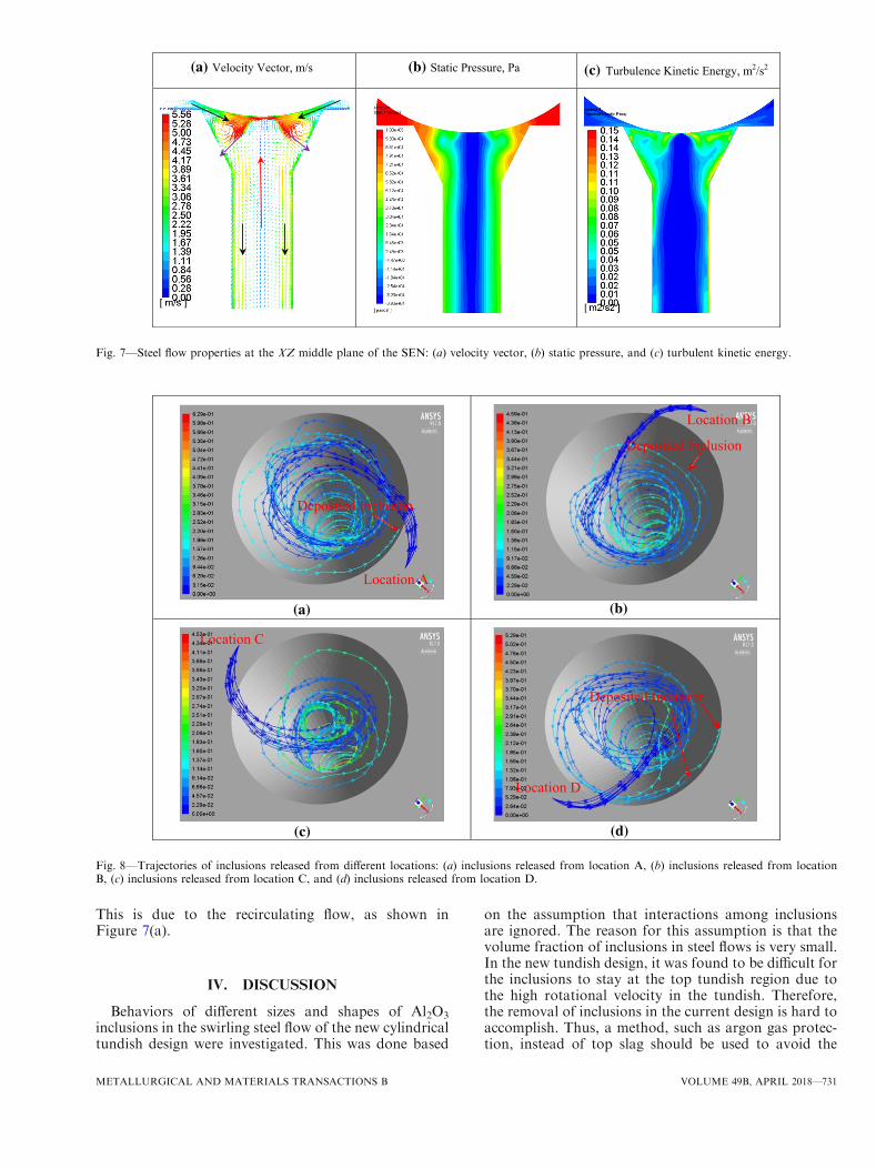
This is due to the recirculating flow, as shown inFigure 7(a).
IV. DISCUSSION
Behaviors of different sizes and shapes of Al2O3
inclusions in the swirling steel flow of the new cylindricaltundish design were investigated. This was done based
on the assumption that interactions among inclusionsare ignored. The reason for this assumption is that thevolume fraction of inclusions in steel flows is very small.In the new tundish design, it was found to be difficult forthe inclusions to stay at the top tundish region due tothe high rotational velocity in the tundish. Therefore,the removal of inclusions in the current design is hard toaccomplish. Thus, a method, such as argon gas protec-tion, instead of top slag should be used to avoid the
(a) Velocity Vector, m/s (b) Static Pressure, Pa (c) Turbulence Kinetic Energy, m2/s2
Fig. 7—Steel flow properties at the XZ middle plane of the SEN: (a) velocity vector, (b) static pressure, and (c) turbulent kinetic energy.
Location A
Location B
Location C
Location D
(c)
(a) (b)
(d)
Deposited Inclusion
Deposited Inclusion
Deposited Inclusion
Fig. 8—Trajectories of inclusions released from different locations: (a) inclusions released from location A, (b) inclusions released from locationB, (c) inclusions released from location C, and (d) inclusions released from location D.
METALLURGICAL AND MATERIALS TRANSACTIONS B VOLUME 49B, APRIL 2018—731

reoxidation of steel by air. In the SEN inlet region,many inclusions were predicted to deposit on the wall.This may be due to the complex steel flow, where both arecirculating flow and an intensive turbulent flowexisted. In addition, the steel flow path in Figure 6(a)and the inclusion trajectories in Figure 8 in the SENinlet region show that the inlet flow is not uniform.Therefore, an improved design is required in the future,which aims not to influence the swirling flow intensity.However, it should reduce the inclusion deposition aswell as the possibility for clogging. For example, asmooth transition with a curved inner wall surface at theconnection region between the SEN and the tundishbottom may be a helpful way to obtain a stable steel
flow, and to reduce the inclusion deposition there. Fordifferent shapes of inclusions, it was found that theinfluence of the shape factor of inclusions is moreimportant for large size inclusions compared to smallsize inclusions. This can be easily seen from the results inFigure 4, where the deposited number of nonsphericalinclusions is around 27 pct higher compared to that ofspherical inclusions. In addition, the interaction betweennonspherical inclusions, such as the faceted inclusions,and the refractory wall seems like a plane-plane typeinteraction. According to the research by Zheng et al.,[57]
this kind of interaction is stronger compared to asphere-plane type interaction, namely, the interactionbetween a spherical inclusion and a refractory wall. This
-2.0
-1.5
-1.0
-0.5
0.0
0.5
1.0
1.5
2.0
2.5
0 0.005 0.01 0.015 0.02
Vel
ocity
, m/s
Tangential velocityVertical Velocity
0.000
0.005
0.010
0.015
0.020
0.025
0.030
0 0.005 0.01 0.015 0.02
Tur
bule
nt F
luct
uatio
n, m
2 /s2
Y, m
Isotropic region Anisotropic region Wall region
R=0.02m
X
0 Y
SEN cross section
Fig. 9—Steel flow velocity and Reynolds stresses in different directions along line 1 in the SEN (u0u0 fluctuation is in rotational direction, v0v0
fluctuation is in radial direction, and w0w0 fluctuation is in downward direction).
Table II. Stokes Number of Different Sized Spherical Inclusions in the Swirling Flow SEN
Diameter (lm)
Stokes Number
Shear Stress, 150 Pa Shear Stress, 200 Pa Shear Stress, 250 Pa
1 7.12 9 10�4 9.49 9 10�4 1.19 9 10�3
10 7.12 9 10�2 9.49 9 10�2 1.19 9 10�1
20 2.85 9 10�1 3.80 9 10�1 4.75 9 10�1
40 1.14 1.52 1.90100 7.12 9.49 11.87
732—VOLUME 49B, APRIL 2018 METALLURGICAL AND MATERIALS TRANSACTIONS B

means that nonspherical inclusions may easily stick tothe wall once they move close to the wall compared tospherical inclusions. Therefore, nonspherical inclusionsmay lead to more serious clogging problems comparedto spherical inclusions. The current investigation aboutthe influence of inclusion shape is simple and is based ona shape factor that is determined by a corrected dragcoefficient. In steel flows, a large number of inclusionsare clusters with an irregular shape. Therefore, effortsare still required to make the inclusion tracking morerealistic.
Simulations of the steel flow in the new tundish havebeen carried out by using the RSM combined with theStress-Omega submodel.[42] The fluid flow and theanisotropy of the turbulent fluctuations in the near-wallboundary layer have been solved, since they have beenfound to be important for the predictions of particledepositions in turbulent flows.[40] Figure 9 shows thepredicted Reynolds stresses in three directions along line1 in the swirling flow SEN. Line 1 presents data from theSEN center to the wall in the Y-axis in the SEN crosssection of 0.55 m below the tundish bottom, as shown inFigure 1. It can be seen that there are three regions inthe swirling flow with different turbulent fluctuationbehaviors. In the SEN core region, the turbulentfluctuations are similar in the different directions, withvalues of the Reynolds stresses approaching zero at theSEN center. This means that isotropic turbulent fluctu-ations exist here and that the steel flow is stable withweak turbulence fluctuations. Outside the isotropicfluctuation region, there is an anisotropic turbulentfluctuation region. Here, the tangential steel flow veloc-ity gradually decreases toward the SEN wall. However,the vertical velocity first increases to its maximum valueat the location near the turbulent boundary layer. Then,it decreases to zero at the wall due to a nonslip boundarycondition. This is due to the centrifugal effect. Therotational steel flow tends to move to the SEN wall dueto its inertia. This creates a high pressure at thenear-wall region and a very small pressure at the SENcenter region.[42] The high pressure at the near-wallregion combined with the downward gravity leads to ahigh downward steel flow velocity. However, themomentum of the inertial tangential steel flow willdecrease after steel reaches close to the wall. This is dueto the high flow shear resulting from the flow directionchange because of the curved wall. This can be seenclearly from the high wall shear stress in a previousstudy, with the values in the range of around 100 to 300Pa on the SEN wall.[42] Therefore, the steel flow in thisregion has a high velocity, a high flow shear, and highanisotropic turbulent fluctuations. These kinds of flowcharacteristics are difficult to accurately resolve by usinga k-e type turbulent model, which is especially true whenthe swirling flow intensity is very high. Thus, theinclusion tracking[32–34] based on a k-e type modelsolution faces some challenges to obtain a good descrip-tion of inclusion motion. In the near-wall region, a highgradient of turbulent fluctuation exists, which leads to astrong turbophoresis effect.[16,17,56] This has been con-sidered in the current study with the RSM to resolve the
turbulent boundary layer, while it was ignored inprevious studies.[32–34]
The effect of a swirl flow on the inclusion separation isan important concern for a swirling flow SEN. This isdue to the fact that light inclusions might be separatedby the swirling flow due to their lower density than steel.The interaction between a particle and a fluid cangenerally be evaluated by the Stokes number, which canbe expressed as follows:
StV ¼ spsf ½11�
sp ¼qpd
2p
18l½12�
where sp is the particle momentum (velocity) responsetime and sf is the characteristic time of the flow fieldsf ¼ m
u2s.[58,59] The parameter us is the friction velocity,
which can be evaluated by using the following expres-
sion: us ¼ffiffiffiffiffiffiffiffiffiffiffiss=qf
p, where ss is the wall shear stress.
The Stokes number is a ratio of the response time ofthe particles to the characteristic time associated withthe flow field.Table II shows the values of the Stokes number of
spherical inclusions of different sizes in the swirling flowSEN. The values of the wall shear stress needed in thecalculations are taken from a previous study,[42] wherethe flow field for the same setup as the current study wascalculated and is, therefore, not repeated in the currentstudy. The values of 150, 200, and 250 Pa were used tocalculate the Stokes number of different size inclusions,since the values of the shear stresses on the SEN wall aremostly in this range.[42] It can be seen that the Stokesnumber of small size inclusions, e.g., 1 lm, is very small.This illustrates that small size inclusions can firmlyfollow the steel flow and that they are difficult toseparate in the current swirling flow SEN. Inclusionswith a diameter of 40 lm have a Stokes number largerthan 1. This illustrates that their response time is largerthan their flow characteristic time. Therefore, theseinclusions will not firmly follow the steel flow path. Thisgives light inclusions the chance or time to respond toother forces, e.g., to be separated in a swirling flow dueto the centripetal effect. As shown in Figure 7(b), a largepressure gradient exists from the SEN wall to the SENcenter. This may cause a separation of light nonmetallicinclusions toward the swirling flow center.The Stokes number only gives the particle response
ability to the flow change. However, it cannot describethe separation ability of light inclusions in a swirlingsteel flow. The separation of light inclusions in a swirlingfluid flow, which results from a centripetal force in theradial direction of the cylindrical coordinates or apressure gradient force in an inertial frame of reference,depends on the relationship between the scale of theparticle residence time and the scale of the centripetalseparation time. Therefore, a dimensionless number wasdefined in this article to describe the separation ability oflight inclusions. This is the Separation number, which
METALLURGICAL AND MATERIALS TRANSACTIONS B VOLUME 49B, APRIL 2018—733

may be expressed as S ¼ sres=sc and which represents the
ratio of the above two timescales. Here, sres representsthe existing time of a particle in a swirling flow and screpresents the time required for the particle to move adistance equal to the pipe radius in the radial directionof a swirling flow. If sres � sc, it means that the particlehas enough existing time in the swirling flow and may beseparated by the centripetal force. However, if sres � sc,it means that the particle passes the swirling flow soquickly that it has no time to respond to the centripetalforce. Therefore, the Separation number represents theability of a particle to be separated to move toward theswirling flow center or outside when it is present in aswirling flow. In a cylindrical coordinate system, thecentripetal separation time scale, sc, can be calculated byusing the following equations by considering the dragforce and the centripetal force in the radial direction:[34]
sc ¼ Rvp;r ½13�
uf;r � vp;r� �
spþ 1
r
qfqp
u2f;h � v2p;h
!
¼ 0 ½14�
sp ¼qpd
2p
18l½15�
where R is the radius of the SEN and uf;h and vp;h arethe tangential velocity of the fluid and particle, respec-tively. Furthermore, vp;r is the particle centripetalvelocity. It can be obtained with the assumption thatthe radial fluid velocity, uf;r, and the tangential particlevelocity, vp;h, are equal to 0 m/s, respectively. The par-ticle residence time in the swirling flow can either beobtained by tracking a particle using a Lagrangiantracking scheme by using commercial software or beevaluated by using Eq. [17] to consider the force bal-ance, including the drag, gravity, and buoyancy forces:
sres ¼ Lvp;a ½16�
uf;a � vp;a� �
spþ g 1� qf
qp
!
¼ 0 ½17�
where L is the length of the swirling flow in the axialdirection with a value of 0.65 m in the current study.The parameters uf;a and vp;a are the fluid and particlevelocity in the axial direction of cylindrical coordi-nates, respectively. The parameter uf;a can simply berepresented by using the average velocity in the axialdirection. It is assumed to have a value of 1.1 m/s inthe current study.
The Separation number for different sizes of sphericalAl2O3 inclusions in the swirling flow SEN is shown inFigure 10. The average maximum tangential velocity,uf;h ¼ 2:625m=s, on four cross sections (shown in
Figure 1) of the SEN and its distance to the SENcenter, r = 0.014 m, were used in the calculation. It canbe seen that small inclusions have a very small separa-tion number, such as a value of 8.7 9 10�4 for a 1-lminclusion. This illustrates that they cannot be separatedin the current swirling flow. At a point when theinclusion size is in the range of 20 to 40 lm, the particleresidence time is equal to the centripetal time. For40-lm inclusions, the separation number is 1.4, whichillustrates that inclusions of this size have the possibilityto be separated in the current swirling flow. This alsoexplains the large performance difference for the differ-ent sizes of Al2O3 inclusions, as shown in Figure 4.More specifically, the deposited number of 40-lminclusions is much smaller than that of 20-lm inclusions,due to their movement toward the SEN center becauseof the centripetal effect. Therefore, the defined Separa-tion number is a useful dimensionless number todescribe the particle separation ability in a swirling flow.The calculated swirl number in the swirling flow SEN
was in the range of around 1.08 to 1.6, which indicates astrong swirling flow.[42] It was found effective in reduc-ing the deposition of large size inclusions. In the currentswirling flow, a high wall shear stress exists. This may bebeneficial to prevent the attachment of inclusions on theSEN wall. At the same time, a high shear stress may alsoproduce new inclusions due to the erosion of therefractory. This issue should be experimentally verifiedin the future. In addition, inclusions were assumed todeposit on the SEN wall once they touch the wall. Thisis due to the fact that the particle-wall interaction is acomplex phenomenon. Thus, a ‘‘stick’’ wall boundarycondition is commonly used. In reality, some inclusionsmay move back to the steel flow rather than stick on theSEN wall after they touch the wall. Therefore, it isnecessary to develop a new model to describe theparticle behavior on the liquid-wall interface.
V. CONCLUSIONS
The behaviors of different sizes and shapes of inclu-sions in a newly designed tundish were investigated byusing a Lagrangian particle tracking method. The mainconclusions for this study are as follows.
0123456789
10
1 10 20 40 100
Sepa
ratio
n N
umbe
r
Inclusion Diameter, m
c = res
Fig. 10—Separation number of different inclusion sizes in the cur-rent study.
734—VOLUME 49B, APRIL 2018 METALLURGICAL AND MATERIALS TRANSACTIONS B

1. Inclusions in the cylindrical tundish are difficult toremove, since a strong rotational flow exists at theregion near the top surface of the tundish. This highrotational flow provides the required momentum fora strong swirling flow later inside the SEN.
2. The inclusion deposition in the swirling flow SENwas studied. It was found that large size inclusionshave a smaller number of deposited inclusions,compared to small size inclusions. This means thatthe swirling flow is effective in separating large sizeinclusions, e.g., 40 and 100 lm. These large inclusionshave a Separation number larger than 1. For non-spherical inclusions, large size inclusions have around27 pct higher number of deposited inclusions com-pared to spherical inclusions.
3. The swirling steel flow shows three regions, namely,the center isotropic turbulent region, the anisotropicturbulent region, and the near-wall region. In orderto have a good description of the inclusion motion inthis complex flow, the anisotropic turbulent fluctua-tions should be taken into account.
4. In the SEN inlet region, some inclusions deposited onthe wall. The plotted velocity distribution shows thatthe SEN inlet flow is not uniform and that the flow isvery chaotic. It has a high turbulent kinetic energy inthis region, and a recirculating flow exists there.These flow phenomena promote the inclusion depo-sition in this region. Therefore, a further improveddesign of the SEN inlet region should be developed inthe future to reduce the probability of an inclusiondeposition.
ACKNOWLEDGMENTS
One of the authors (PN) thanks the National Natu-ral Science Foundation of China (Grant No.51704062) for the support on this work.
OPEN ACCESS
This article is distributed under the terms of theCreative Commons Attribution 4.0 International Li-cense (http://creativecommons.org/licenses/by/4.0/),which permits unrestricted use, distribution, and re-production in any medium, provided you give appro-priate credit to the original author(s) and the source,provide a link to the Creative Commons license, andindicate if changes were made.
REFERENCES
1. K. Chattopadhyay, M. Isac, and R.I.L. Guthrie: ISIJ Int., 2010,vol. 50, pp. 331–48.
2. Y. Sahai: Metall. Mater. Trans. B, 2016, vol. 47B, pp. 2095–2106.3. Y. Miki and B.G. Thomas: Metall. Mater. Trans. B, 1999,
vol. 30B, pp. 639–54.4. H. Ling and L. Zhang: JOM, 2013, vol. 65, pp. 1155–63.5. L. Zhang: Steel Res. Int., 2005, vol. 76, pp. 784–96.
6. C. Chen, P. Ni, L.T.I. Jonsson, A. Tilliander, G. Cheng, and P.G.Jonsson: Metall. Mater. Trans. B, 2016, vol. 47B, pp. 1916–32.
7. L. Zhang, S. Taniguchi, and K. Cai:Metall. Mater. Trans. B, 2000,vol. 31B, pp. 253–66.
8. R. Schwarze, F. Obermeier, J. Hantusch, A. Franke, and D.Janke: Steel Res. Int., 2001, vol. 72, pp. 215–20.
9. Q. Yuan, B.G. Thomas, and S.P. Vanka: Metall. Mater. Trans. B,2004, vol. 35B, pp. 703–14.
10. L. Zhang, Y. Wang, and X. Zuo: Metall. Mater. Trans. B, 2008,vol. 39B, pp. 534–50.
11. M. Mohammadi-Ghaleni, M.A. Zaeem, J.D. Smith, and R.O’Malley: Metall. Mater. Trans. B, 2016, vol. 47B, pp. 3056–65.
12. E. Gutierrez, S. Garcia-Hernandez, and J.J. Barreto: ISIJ Int.,2016, vol. 56, pp. 1394–1403.
13. E. Gutierrez, S. Garcia-Hernandez, and J.J. Barreto: Steel Res.Int., 2016, vol. 87, pp. 1406–16.
14. M. Long, X. Zuo, L. Zhang, and D. Chen: ISIJ Int., 2010, vol. 50,pp. 712–20.
15. P. Ni, L.T.I. Jonsson, M. Ersson, and P.G. Jonsson: Steel Res.Int., 2017, vol. 88, Article No. 1600155.
16. P. Ni, L.T.I. Jonsson, M. Ersson, and P.G. Jonsson: Int. J. Mul-tiphase Flow, 2014, vol. 62, pp. 152–60.
17. P. Ni, L.T.I. Jonsson, M. Ersson, and P.G. Jonsson: Metall.Mater. Trans. B, 2014, vol. 45B, pp. 2414–24.
18. Z. Liu and B. Li: Powder Technol., 2016, vol. 287,pp. 315–29.
19. B. Li and F. Tsukihashi: ISIJ Int., 2003, vol. 43, pp. 923–31.20. Y. Ho and W. Hwang: ISIJ Int., 2003, vol. 43, pp. 1715–23.21. H. Yu and M. Zhu: ISIJ Int., 2008, vol. 48, pp. 584–91.22. S. Lei, J. Zhang, X. Zhao, and K. He: ISIJ Int., 2014, vol. 54,
pp. 94–102.23. Y. Wang, A. Dong, and L. Zhang: Steel Res. Int., 2011, vol. 82,
pp. 428–39.24. L. Zhang, J. Aoki, and B.G. Thomas: Metall. Mater. Trans. B,
2006, vol. 37B, pp. 361–79.25. B.G. Thomas, Q. Yuan, S. Mahmood, R. Liu, and R. Chaudhary:
Metall. Mater. Trans. B, 2014, vol. 45B, pp. 22–35.26. S. Yokoya, Y. Asako, S. Hara, and J. Szekely: ISIJ Int., 1994,
vol. 34, pp. 883–88.27. S. Yokoya, R. Westoff, Y. Asako, S. Hara, and J. Szekely: ISIJ
Int., 1994, vol. 34, pp. 889–95.28. S. Yokoya, S. Takagi, M. Iguchi, Y. Asako, R. Westoff, and S.
Hara: ISIJ Int., 1998, vol. 38, pp. 827–33.29. S. Yokoya, S. Takagi, M. Iguchi, K. Marukawa, and S. Hara: ISIJ
Int., 2000, vol. 40, pp. 578–83.30. Y. Tsukaguchi, O. Nakamura, P. Jonsson, S. Yokoya, T. Tanaka,
and S. Hara: ISIJ Int., 2007, vol. 47, pp. 1436–43.31. Y. Tsukaguchi, H. Hayashi, H. Kurimoto, S. Yokoya, K. Mar-
ukawa, and T. Tanaka: ISIJ Int., 2010, vol. 50, pp. 721–29.32. Y. Yang, P.G. Jonsson, M. Ersson, and K. Nakajima: Steel Res.
Int., 2015, vol. 86, pp. 341–60.33. Y. Yang, P.G. Jonsson, M. Ersson, Z. Su, J. He, and K. Naka-
jima: Steel Res. Int., 2015, vol. 86, pp. 1312–27.34. P. Ni, L. Jonsson, M. Ersson, and P. Jonsson: Steel Res. Int., 2016,
vol. 87, pp. 1356–65.35. H. Sun and J. Zhang: Metall. Mater. Trans. B, 2014, vol. 45B,
pp. 936–46.36. H. Liu, M. Xu, S. Qiu, and H. Zhang: Metall. Mater. Trans. B,
2012, vol. 43B, pp. 1657–75.37. B. Wang, W. Chen, Y. Chen, and Y. Feng: Ironmak. Steelmak.,
2015, vol. 42, pp. 63–69.38. L.B. Trindade, J.E.A. Nadalon, A.C. Contini, and R.C. Barroso:
Steel Res. Int., 2017, vol. 88, Article No. 1600319.39. Q. Hou, Q. Yue, H. Wang, Z. Zou, and A. Yu: ISIJ Int., 2008,
vol. 48, pp. 787–92.40. L. Tian and G. Ahmadi: Aerosol Sci., 2007, vol. 38, pp. 377–97.41. H. Bai, M. Ersson, and P.G. Jonsson: ISIJ Int., 2016, vol. 56,
pp. 1404–12.42. P. Ni, D. Wang, L.T.I. Jonsson, M. Ersson, T. Zhang, and P.G.
Jonsson: Metall. Mater. Trans. B, 2017, vol. 48B, pp. 2695–2706.43. B.E. Launder, G.J. Reece, and W. Rodi: J. Fluid Mech., 1975,
vol. 68, pp. 537–66.44. F.S. Lien and M.A. Leschziner: Comput. Fluids, 1994, vol. 23,
pp. 983–1004.45. ANSYS Fluent Theory Guide: Release, 2016, vol. 17, p. 85.
METALLURGICAL AND MATERIALS TRANSACTIONS B VOLUME 49B, APRIL 2018—735

46. D.C. Wilcox: Turbulence Modeling for CFD, DCW Industries Inc,La Canada, CA, 1998.
47. G.V. Samsonov, C.N. Turton, and T.I. Turton: The OxideHandbook, IFI/Plenum, New York, NY, 1973.
48. A. Li and G. Ahmadi: Aerosol Sci. Technol., 1992, vol. 16,pp. 209–26.
49. P.G. Saffman: J. Fluid Mech., 1965, vol. 22, pp. 385–400.50. S.A. Morsi and A.J. Alexander: J. Fluid Mech., 1972, vol. 55,
pp. 193–208.51. A. Haider and O. Levenspiel: Powder Technol., 1989, vol. 58,
pp. 63–70.52. A.D.Gosman andE. Ioannides: J. Energy, 1983, vol. 7, pp. 482–90.53. D.I. Graham: Int. J. Multiphase Flow, 1998, vol. 24, pp. 335–45.
54. V. Seshadri, C.A. Silva, I.A. Silva, and E.S.A. Junior: Technol.Metall. Mater. Miner., 2012, vol. 9, pp. 22–29.
55. M.A.G. Timmer, J.P. Oosterhuis, S. Buhler, D. Wilcox, and T.H.Meer: J. Acoust. Soc. Am., 2016, vol. 139, pp. 193–203.
56. P. Ni, L. Jonsson, M. Ersson, and P. Jonsson: Int. J. Heat FluidFlow, 2016, vol. 62, pp. 166–73.
57. L. Zheng, A. Malfliet, P. Wollants, B. Blanpain, and M. Guo: ISIJInt., 2016, vol. 56, pp. 926–35.
58. C.T. Crowe, J.D. Schwarzkopf, M. Sommerfeld, and Y. Tsuji:Multiphase Flows with Droplets and Particles, 2nd ed., CRC Press,Taylor & Francis Group, Boca Raton, FL, 2012.
59. F. Zonta, C. Marchioli, and A. Soldati: Int. J. Multiphase Flow,2013, vol. 56, pp. 172–83.
736—VOLUME 49B, APRIL 2018 METALLURGICAL AND MATERIALS TRANSACTIONS B