a survey of subdivision-based tools for surface...
TRANSCRIPT

DIMACS Series in Discrete Mathematicsand Theoretical Computer Science
A Survey of Subdivision-Based Tools for Surface Modeling
Ioana Boier-Martin, Denis Zorin, and Fausto Bernardini
This paper is dedicated to Henning Biermann, in memoriam.
Abstract. Subdivision surfaces have emerged as a powerful representation forsurface modeling and design. They address important limitations of traditionalspline-based methods, such as the ability to handle arbitrary topologies andto support multiscale editing operations. In this paper we survey existingsubdivision-based modeling methods with emphasis on interactive tools forstyling and decoration of 3D models.
1. Introduction
Subdivision surfaces offer several advantages over both irregular meshes andspline patches, two of the most commonly used surface representations today. Sub-division offers a compact way to represent geometry with minimal connectivityinformation. It generalizes the classical spline patch approach to arbitrary topol-ogy, it naturally accommodates multiple levels of detail, and produces meshes withwell-shaped elements arranged in almost regular structures, suitable for digital pro-cessing. When combined with multiresolution analysis, subdivision offers a powerfulmodeling tool, allowing for complex editing operations to be applied efficiently atdifferent resolutions.
In recent years, the set of tools available for manipulating subdivision surfaceshas been growing steadily. Algorithms for direct evaluation [Sta98, ZK02], edit-ing [BKZ01, BMBZ02, BMZB02, BLZ00], texturing [PB00], and conversionto other popular representations [Pet00] have been devised and hardware sup-port for rendering of subdivision surfaces has been proposed [BAD+01, BKS00,PS96].
This survey focuses on the use of subdivision-based representations for stylingand conceptual design. We explore various methods for manipulating subdivisionsurfaces and, whenever possible, we illustrate the evolution of such methods fromrelated representations. We pay particular attention to interactive tools which aresuitable for design as they allow the designer to instantaneously evaluate results.While we are trying to provide a thorough overview of the area and include the mostrelevant methods, we realize that the volume of published work goes well beyond
Key words and phrases. Subdivision surfaces, geometric modeling.
c©0000 (copyright holder)
1

2 IOANA BOIER-MARTIN, DENIS ZORIN, AND FAUSTO BERNARDINI
that covered in this survey which is by no means exhaustive (see also [DL02,Sab02] for additional surveys). Many of the topics presented relate to issues wehave addressed in our own work which we hope will provide some insights to thosepursueing similar interests.
2. Background
The basic idea of using subdivision to produce smooth curves and later, smoothsurfaces, has been around for many years (see [ZSD+00] for a brief incursion intothe history of subdivision). However, it is only recently that powerful design toolsbased on this representation have emerged. This is partly due to the recent advent ofmultiresolution techniques that facilitate capturing of non-trivial shapes and partlydue to even more recent advances in subdivision theory and methods for directand efficient evaluation of subdivision surfaces. For the purpose of this survey, weprovide a brief review of the basic concepts pertaining to subdivision surfaces. Foradditional details we refer the reader to [ZSD+00, WW01].
Subdivision defines a smooth surface recursively as the limit of a sequence ofmeshes (see Figure 1). Each finer mesh is obtained from a coarse mesh by usinga set of refinement rules which define a subdivision scheme. Many schemes havebeen proposed in the literature. Examples include Doo-Sabin [DS78], Catmull-Clark [CC78], Loop [Loo87], Butterfly [DLG90, ZSS96], Kobbelt [Kob96a],Midedge [PR97]. Different schemes lead to limit surfaces with different smoothnesscharacteristics. For design purposes, the Catmull-Clark [CC78], Loop [Loo87]schemes are most often employed as they are closely related to splines (a de-factostandard in modeling today) and generate C2-continuous surfaces over arbitrarymeshes.
Figure 1. Subdivision defines a smooth surface recursively as thelimit of a sequence of meshes.
Multiresolution subdivision extends the concept of subdivision by allowing de-tail vectors to be introduced at each level. Hence, a finer mesh is computed byadding detail offsets to the subdivided coarse mesh. Given a semi-regular mesh, i.e.,a mesh with subdivision connectivity, it can be easily converted to a multiresolutionsurface by defining a smoothing operation to compute a coarse level from a finerlevel. The details are then computed as differences between levels. This representa-tion was introduced by several authors in different forms [LDW97, PL97, ZSS97].Figure 2 illustrates the power of multiresolution in capturing complex shapes.
A close connection exists between multiresolutin subdivision and wavelets [SDS96].In particular, two operations known as Synthesis and Analysis can be defined topropagate data from coarse to fine and in reverse throughout the subdivision hier-archy, similar to wavelet transforms. Analysis computes positions of control points

A SURVEY OF SUBDIVISION-BASED TOOLS FOR SURFACE MODELING 3
Figure 2. Top: multiresolution subdivision extends the conceptof subdivision by introducing detail vectors at each level. Bottom:surfaces obtained by subdivision of the same coarse mesh look verydifferent depending on the amount of detail introduced and thelevel at which it is introduced. From left to right: no details toprogressively more details added on finer levels.
on a coarse level i − 1 by applying a smoothing filter to points on level i. Mul-tiresolution details on level i are computed as differences between the two levels.Conversely, Synthesis reconstructs the data on level i by subdividing the controlmesh of level i − 1 and adding the details [ZSS97].
An important property of subdivision surfaces is that they can be naturallyinterpreted as functions on the domain defined by the base mesh (see Figure 3).This parametric interpretation is useful in many circumstances related to design,from derivation of differential quantities to dealing with constraints along arbitrarycurves as described in section 3. Figure 3 illustrates this natural parameterization.
3. Surface Modeling Tools
3.1. Free-Form Editing. Free-form manipulation of 3D models is a popularmethod for modifying existing shapes which attempts to mimic to a certain extentthe process of modeling or sculpting a physical object by hand. The applications arenumerous, from animated character creation, to virtual restorations, to industrialdesign.
The sculpting metaphor for geometric modeling has its roots in the parametricsurface works of Sabin [Sab71] and Bezier [Bez74] which contain early mentionsof surface deformations. Subsequent work has spanned more than three decadesand continues to be investigated in the context of modern systems and surfacerepresentations (e.g., [Bar84, SP86, Coq90, HKD93, CR94, MJ96, SF98,Kob96b, ZSS97, PL97, QMV98, Tak98, WW98, MQ00, TO02, GS01,BMRB04].
The basic idea of free-form modeling is to introduce a degree of transparencybetween the designer and the mathematical model of the surface being shaped.Instead of controlling the shape through a set of non-intuitive surface parame-ters, free-form deformations allow the shape to be controlled through intuitive

4 IOANA BOIER-MARTIN, DENIS ZORIN, AND FAUSTO BERNARDINI
Figure 3. Natural parameterization of a subdivision surface.Each time we apply the subdivision rules to compute the finercontrol mesh we also apply midpoint subdivision to a copy of theinitial control mesh. A mapping from a denser and denser subsetof the control polyhedron (left) to the control points of a finer andfiner control mesh (right) is obtained through repeated subdivision.In the limit, a map from the control polyhedron to the surface isobtained.
manipulation of the surface itself or the space surrounding it. The main chal-lenge is to perform the manipulation through a limited set of controls and todefine natural deformations of the surface away from the control positions. Dif-ferent variations of this paradigm have been developed, including axial deforma-tions [Bar84, CST94, LCJ94] which alter the axis of a shape to induce its defor-mation, lattice deformations [SP86, Coq90, MJ96] which operate on the cells ofa space lattice to deform the volume inside the lattice, manipulations on scalar fieldembeddings [HQ03], control mesh editing methods which shape parameterically-defined surfaces by imposing constraints on their control meshes [ZSS97], andvariational methods which operate by optimizing an energy functional over thesurface under constraints [Tak98, BMRB04].
We focus our attention on methods that take advantage of subdivision repre-sentations and among these, we emphasize those that support interactive multiscalemodeling. Subdivision representations are particularly suitable for free-form edit-ing due to their hierarchical nature which easily accommodates multiscale edits, aswell as their efficiency in terms of storage and access. For a survey of deformablemodels based on other representations see [GM97].
3.1.1. Control mesh manipulations. Manipulating control meshes offers a straight-forward interface which supports interactive shape deformations. This approach hasbeen extensively employed in spline-based modeling [CRE01] and can be naturallyextended to subdivision surfaces. Collections of control mesh vertices, edges, andfaces are re-positioned so as to induce modifications of the resulting limit surface.In addition, control points can be added and edges and faces can be split to in-crease the complexity of the shape as editing progresses. This type of manipulation
A SURVEY OF SUBDIVISION-BASED TOOLS FOR SURFACE MODELING 5
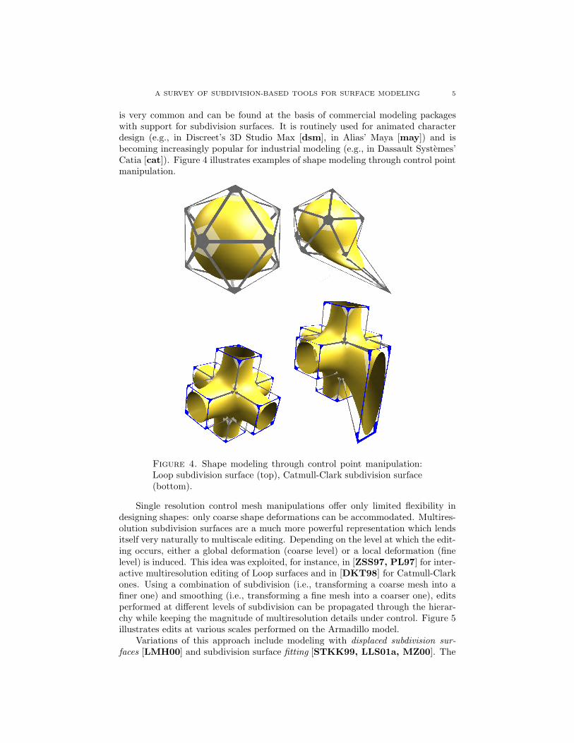
is very common and can be found at the basis of commercial modeling packageswith support for subdivision surfaces. It is routinely used for animated characterdesign (e.g., in Discreet’s 3D Studio Max [dsm], in Alias’ Maya [may]) and isbecoming increasingly popular for industrial modeling (e.g., in Dassault Systemes’Catia [cat]). Figure 4 illustrates examples of shape modeling through control pointmanipulation.
Figure 4. Shape modeling through control point manipulation:Loop subdivision surface (top), Catmull-Clark subdivision surface(bottom).
Single resolution control mesh manipulations offer only limited flexibility indesigning shapes: only coarse shape deformations can be accommodated. Multires-olution subdivision surfaces are a much more powerful representation which lendsitself very naturally to multiscale editing. Depending on the level at which the edit-ing occurs, either a global deformation (coarse level) or a local deformation (finelevel) is induced. This idea was exploited, for instance, in [ZSS97, PL97] for inter-active multiresolution editing of Loop surfaces and in [DKT98] for Catmull-Clarkones. Using a combination of subdivision (i.e., transforming a coarse mesh into afiner one) and smoothing (i.e., transforming a fine mesh into a coarser one), editsperformed at different levels of subdivision can be propagated through the hierar-chy while keeping the magnitude of multiresolution details under control. Figure 5illustrates edits at various scales performed on the Armadillo model.
Variations of this approach include modeling with displaced subdivision sur-faces [LMH00] and subdivision surface fitting [STKK99, LLS01a, MZ00]. The

6 IOANA BOIER-MARTIN, DENIS ZORIN, AND FAUSTO BERNARDINI
Figure 5. Multiresolution editing according to [ZSS97]: left –input model; right – editing result. Note the large-scale edit of thebelly and the fine-scale edit around the chin.
displaced representation can be viewed as a restricted form of multiresolution sub-division consisting of a control mesh and a single level of scalar details. A domainsurface is generated from the control mesh using Loop subdivision [Loo87]. Adisplacement map computed from the scalar displacement is then applied over thedomain to generate the final surface. The displacements can be edited to createfine-level features on the surface, while control mesh edits lead to global shape al-terations. In surface fitting a surface is deformed to conform to the shape of anothergiven data set (e.g., points, curves, another surface). This approach is somewhatdifferent than those discussed so far in that it is less suitable for interactive ma-nipulation. Typically some optimization of the surface being fitted is performed inorder to determine optimal control point positions which lead to a best fit betweenthe surface and the target. The accuracy of the fit is controlled through a thresholdparameter that bounds the error between the target and the fitted surface.
3.1.2. Variational design. Variational surface design operates on the principleof modifying a shape so that its fairness is optimized. Surface fairness is typicallymeasured in terms of its energy and the idea is to find a minimum-energy statewhich, in turn, corresponds to the fairest possible shape. In Computer Graphics,energy-minimizing surfaces became popular in the context of simulating physicalproperties of materials [Bar84, TF88, WW92]. Celniker and Gossard [CG99]and later Welch and Witkin [WW92] pointed out the relationship between fairsurface design and energy minimization.
Most commonly, fairness is expressed as an integral of a physical parameterassociated with a real object bearing the shape of the surface [Hal96]. A widelyused measure of fairness is the combination of stretching and bending energies:
(3.1) Energy(S) = α
∫||I||2dS + β
∫||II||2dS

A SURVEY OF SUBDIVISION-BASED TOOLS FOR SURFACE MODELING 7
Figure 6. Local quadratic interpolant used to approximate firstand second order derivatives [BMRB04].
where I and II denote the first and second fundamental forms of the surface and|| · || is a suitably chosen matrix norm [TPBF87].
For practical purposes, discretized linear forms of equation (3.1) using para-metric derivatives are typically employed:
(3.2) Estretch ≈∫
Ω
(∂S
∂u
)2
+(
∂S
∂v
)2
dudv
(3.3) Ebend ≈∫
Ω
(∂2S
∂u2
)2
+ 2(
∂2S
∂u∂v
)2
+(
∂2S
∂v2
)2
dudv
where Ω denotes the parametric domain of the surface S. Most variational ap-proaches take advantage of these expressions, although alternative approaches havebeen proposed (e.g., [CSA+02]). The main differences are in the types of parame-terizations used to derive the differential quantities. For example, Greiner [Gre94]and later Kobbelt [Kob96a] suggested a discrete exponential map for local param-eterizations (see Figure 6) such that each vertex P0 has coordinates (0, 0) and its1-ring neighbors Pi ∈ R(P0) are assigned coordinates:
(3.4) (ui, vi) = ei
⎛⎝cos
⎛⎝ ∑
j∈R(P0)
αj
⎞⎠ , sin
⎛⎝ ∑
j∈R(P0)
αj
⎞⎠
⎞⎠
where
(3.5) αj =2π∠(P l
jPl0P
lj+1)∑
j∈R(0)
∠(P ljP
l0P
lj+1)
.
In the context of subdivision surfaces, Halstead et al. [HKD93] were amongthe first to describe a method for interpolating a given shape with a Catmull-Clark surface while minimizing surface fairness. Given the lack of a ”natural”parameterization near extraordinary points, they re-formulated the stretch andthin-plate energy definitions in terms of the control meshes at different subdivisionlevels (rather than the limit surface). In their method subdivision is used to isolate

8 IOANA BOIER-MARTIN, DENIS ZORIN, AND FAUSTO BERNARDINI
extraordinary vertices and bi-cubic spline evaluation is used to evaluate the fairnessnorm away from such vertices.
Kobbelt [Kob96b] introduced the concept of variational subdivision to createinterpolatory subdivision rules that place newly inserted vertices so as to minimizea global energy functional. Using a similar idea, Weimer and Warren [WW98]propose two schemes for variational subdivision of thin-plate splines. One schemeprovides an exact solution to the variational problem, but the subdivision matrixhas to be recomputed at every subdivision level. The other scheme is only approx-imate, but has the advantage that rules can be precomputed. Both schemes arerestricted to rectilinear grids. Another method which connects subdivision withfairing and cascading multigrid methods was proposed in [DMR02]. The basicidea in this case is to interpret the evolution of the surface under curvature motionas a filtering proces.
Later on, Friedel et al. [FMS03] proposed using the characteristic map parametriza-tion to construct first order data-dependent energies. This leads to a nonlinearminimization problem which is solved by re-writing the surface energy as a linearcombination of precomputed stiffness matrices.
Constraints play an important role in variational design methods. In theirabsence, the optimization problem has a trivial solution, which usually leads to thecollapse of the surface to a single point (an exception is the method of Boier-Martinet al. [BMRB04] in which the trivial solution corresponds to the input surface).We distinguish between two classes of constraints [WW92]:
• Finite-dimensional: involve point and normal constraints at discrete loca-tions on the surface. These are the most commonly used. Point constraintsare used to enforce spatial interpolation conditions. For subdivision sur-faces such constraints typically correspond to control points and are easyto implement by solving linear systems. Normal constraints are used to en-force surface normals at certain points on a surface. Different approachescan be used to constrain normals: expressing the fact that two tangentvectors must be perpendicular to the prescribed normal, enforcing the po-sitions of the vertices of a given face so that the face normal coincides withthe prescribed one, or constraining tangent vectors rather than normals(the last two tend to over-constrain the problem).
• Transfinite: involve one or two-dimensional surface entities such as embed-ded curves and patches. Curve constraints are among the most common inthis category. Enforcing such constraints involves solving an integral overthe entity. For example, to constrain a surface curve C(t) = S(u(t), v(t))along a given space curve C0(t), the following must be satisfied:
(3.6)∫
(C − C0)2 = 0
Such constraints are usually discretized and enforced either by usinga least-squares approach [WW92] or by reparameterizing the surface toalign control points or edges with constraints [BMRB04] (see also Algo-rithm 1 in section 3.2). An alternative approach is to evaluate the curvesand to incorporate the result of the evaluation into the subdivision rules

A SURVEY OF SUBDIVISION-BASED TOOLS FOR SURFACE MODELING 9
to produce a limit surface that interpolates the curves. This is the ob-ject of combined subdivision schemes [Lev99] (see also [Nas00, NA02,SWZ04]).
Figure 7 illustrates the result of modeling with various types of constraints.
(a) (b)
(c) (d)
Figure 7. Constraint types: (a)-(b) point and discretized curveconstraints; (c)-(d) normal constraints.
Another important consideration in dealing with constraints is the region ofinfluence of a constraint. It is defined as the portion of the surface affected by theconstraint. The region of influence can be explicitly enforced [Kob00] by lettingthe designer encircle an area on the surface. This generates boundary constraintsbetween the surface inside the area of influence and the rest of the surface. Alter-natively, in the case of hierarchical representations such as subdivision hierarchies,the region of influence can be controlled indirectly through the levels at which con-straints are defined. For example, Takahashi et al. [Tak98] impose constraints atvarious scales using a wavelet framework. Constraints are being propagated fromfiner to coarser scales, however, the region of influence of each constraint is notcontrolled in any way. In [BMRB04] the influence of a constraint is explicitly en-forced by the coarse level at which the constraint is propagated. Thus, more global

10 IOANA BOIER-MARTIN, DENIS ZORIN, AND FAUSTO BERNARDINI
or local edits can be performed depending on the level to which the constraint isrestricted: a coarser level will induce a more global deformation, whereas a finerlevel will produce a more local edit (see Figure 8).
A related issue is that of detail preservation. When a global shape changeoccurs, it is often expected that the high frequency details are preserved over themodified surface. The face of Venus in Figure 9 is represented as a multiresolutionsubdivision surface in which non-trivial detail vectors capture the organic shape ofthe model. If a shape deformation is performed by pulling on a single point at thetip of the nose, a naive energy optimization approach leads to a fair shape thatsatisfies the constraints, but all the details of the face are lost (note that boundaryconstraints must also be imposed in this case to avoid the collapse of the surface toa single point). One solution is to separate the high-frequency information beforeoptimization and to ”re-apply” it to the new shape [Kob00]. This introduces anoverhead related to saving and restoring surface details. To avoid this overhead,Boier-Martin et al. [BMRB04] propose to define a vector field of deformationsover the surface and to optimize the energy of this vector field rather than theenergy of the surface itself. Initially all deformation vectors are null. When an editoccurs, the corresponding deformation vector (i.e., at the tip of the nose) becomesnon-null. The optimization procedure tries to smooth the deformation field underthe constraints defined by the non-null vectors. Since the deformations are definedwith respect to the detailed shape, the details are preserved during deformation.Note that, in this case, boundary constraints are not necessary as the rest shape inthe absence of constraints is the input shape.
Figure 8. Region of influence of a multiresolution constraint: left– input model; middle – constraint is propagated to the coarsestsubdivision level, inducing a global deformation of the head bypulling a single point on the nose; right – constraint is propagatedonly two levels coarser inducing a more localized edit.
An added advantage of subdivision hierarchies is that they facilitate the useof multigrid methods [Bri87] to solve the constrained minimization problem. Inthe presence of many constraints, however, even multigrid solvers may be too slowto yield results at interactive rates. A possible solution [BMRB04] is to aim foran approximate solution during interaction and a more accurate (non-interactive)result after the interaction has stopped. Figure 10 illustrates the differences between

A SURVEY OF SUBDIVISION-BASED TOOLS FOR SURFACE MODELING 11
Figure 9. Energy optimization with constraints: left – input mul-tiresolution subdivision surface with details; middle – optimizationwithout detail preservation; right – optimization with detail preser-vation.
a Catmull-Clark approximation obtained at interactive rates and a more accuratemultigrid minimization.
Figure 10. Computing a solution to the energy minimizationproblem with different accuracies: left - input model; middle -Catmull-Clark solution obtained interactively; right - multigrid so-lution.
For completeness, we mention the fact that the evolution of energy over time hasalso been considered to derive dynamic surface models [TQ94, QT96]. Dynamicmodels based on subdivision surfaces have been proposed by Qin et al. [QMV98].Such models are typically too complex to support interactive design operations.
Topology modifications. The free-form modeling methods discussed so far op-erate by deforming the input surface without changing its topology. Some appli-cations, however, may require topological modifications, such as creating handlesand tunnels. An interactive sculpting environment which supports this type ofedits was proposed in [GOP99]. The Localized hierarchy Surface Splines allowadding handles and punching holes, while maintaining C1 continuity across the

12 IOANA BOIER-MARTIN, DENIS ZORIN, AND FAUSTO BERNARDINI
surface which is represented explicitly in piecewise polynomial or spline form. Themain idea behind localized hierarchies is to allow local edits on locally refined meshfragments based solely on coarser level data. Direct manipulation is performed byinteracting directly with the surface rather than with control mesh. The types ofoperations supported include fillets, blends, semi-sharp features, extrusions, holes,and bridges.
Using meshes as an underlying representation, Guskov et al. [GKSS02] proposea user-driven procedure for inducing topological modifications in a semi-regularsetting. The so-called hybrid meshes are multiresolution surface representationswhich enhance subdivision-based refinement operations with irregular operationsthat support changes in topology and approximate detailed features at multiplescales. In [GKSS02], hybrid meshes are defined as quadrilateral meshes on whichregular 1−4 face splits are combined with irregular operations through which groupsof quads are removed and/or replaced.
3.2. Boolean Operations. Boolean operations provide a straightforward ap-proach to creating complex models from simpler ones using intuitive combinations.Addition, subtraction, and intersection can be packaged into editing tools for mod-eling solids bounded by subdivision surfaces.
3.2.1. Mesh-Based Approximations. Traditionally, Boolean operations on bound-ary representations (B-reps) of solids have required intersecting parametric surfaces,removing the unwanted parts, and building new surfaces from the remaining ones.This approach presents a number of challenges, as intersections are difficult toperform for high-order B-reps and often lead to increasingly complex intersectioncurves. Exact matching of surfaces bordering such curves is also problematic, as itis not easy to ensure that curves in different parametric domains coincide in 3D.Consequently, subsequent editing of the resulting models may lead to unwantedartifacts in the surface (e.g., cracks) which require special handling.
A substantially simpler approach, proposed by Linsen [Lin00] is to use thecontrol meshes corresponding to the parametric parts being combined, rather thanthe surfaces themselves. This implies that the intersections between solids are onlyapproximately computed. At the same time, the problem of intersecting arbitrarysurfaces translates into the much simpler one of intersecting arbitrary meshes. Themeshes are first triangulated to avoid difficulties posed by handling of non-planarfaces. Two approaches to building a combined control mesh are discussed: clippingtriangles along the intersection boundaries and connecting intersection points andremoving faces along the intersection curves and remeshing the resulting gaps. Thelatter has the advantage that it produces a more visually pleasing result. The maindrawbacks in both approaches lie in the inefficiency of computing triangle-meshintersections and robustness issues associated with such computations as well asgap filling for arbitrary gap topologies (see also [LFKN03] for variations on thetopic of computing intersection curves for subdivision surfaces).
Using a similar control-mesh based approach, Biermann et al. [BKZ01] pro-pose an approximate scheme for computing Boolean operations which deals withseveral important issues: matching the topology and the geometry of the intersec-tion curve, fitting the resulting surface to the original data, and accurately capturingand representing sharp features in the result. The method uses piecewise-smooth

A SURVEY OF SUBDIVISION-BASED TOOLS FOR SURFACE MODELING 13
multiresolution Loop [Loo87] subdivision surfaces to represent surfaces being com-bined. The algorithm assumes that each part being used in a Boolean operation isbounded by a closed orientable surface. It follows several steps:
(1) Compute intersection curves.(2) Build resulting control mesh and compute an initial parameterization of
the resulting surface over this mesh.(3) Optimize the parameterization from the previous step.(4) Use multiresolution fitting to approximate the input data as closely as
possible.
For the first step, the authors improve on both the efficiency and the robustnessof the naive mesh-mesh intersection approach by using bounding box hierarchies toaccelerate computations and a perturbation scheme [Sei98] to increase robustness.
After determining the topology of the intersection, control meshes are mergedwith special consideration for several issues: preserving the topology of the cut,inserting a minimal number of new vertices, and keeping their valence small. Theinput control meshes are cut along intersection curves and a new control meshis combined from the remaining pieces. The cutting process takes advantage ofthe natural parameterization of subdivision surfaces over their control meshes (seesection 2) to approximate the intersection curve by alternating so-called Snappingand Refinement steps:Algorithm 1 (snapping and refinement):
Given a domain mesh M and an intersection curve c(t) in MRepeat
For each vertex v of a triangle intersected by c do1. Find α ∈ c closest to v2. Snap v to α if possible
Adaptively refine parameterizationuntil (curve adequately approximated)
Snapping is performed between points of the curve and parametric mesh ver-tices, if they are sufficiently close. While optional, this step considerably reducesthe complexity of the resulting domain (fewer faces). The role of the refinementis to increase the accuracy with which intersection curves are approximated. Itis typically performed by midpoint subdivision of triangles which are intersectedby curves multiple times or which fully contain curves. Figure 11 illustrates thisprocess. The output of this step consists of piecewise linear approximations ofthe intersection curves, either along input edges or along newly introduced edgesobtained by splitting triangles.
After cutting, the portions of the control meshes not required in the Booleanoperation are removed and the meshes are joined along their boundaries. This isalso done in two steps: vertices along one boundary are paired to correspondingvertices along the other boundary. When correspondences do not exist, trianglesalong the boundary are refined so as to introduce new vertices. Paired vertices closeto one-another are merged together. During merging, intersection curves are alsotagged with sharp feature tags (see also section 3.3).
By construction, the resulting merged control mesh constitutes a parameter-ization domain with the property that every one of its vertices belongs to one of

14 IOANA BOIER-MARTIN, DENIS ZORIN, AND FAUSTO BERNARDINI
Figure 11. Refinement and snapping: two steps of refinement areshown on the left. The image of the curve in parameter space andvertex snapping are shown on the right (see [BKZ01]).
the original domains. However, the initial parameterizations of the parts of theinput models corresponding to the Boolean operation may not be optimally pa-rameterized over the new domain. An optimization procedure is used to reduce thedistortion of the resulting surface over the new domain.
The last step of this method computes optimal positions of control points giventhe previously computed parameterization. The merged control mesh is subdivideda number of times and the resulting mesh is fitted to the original data in least-squares sense. Results of Boolean operations obtained with this method are shownin Figure 12.
Figure 12. Boolean operations on multireolution subdivision surfaces [BKZ01].
3.2.2. Surface Cut-and-Paste. Surface pasting can be viewed as an instance of aBoolean operation. The basic paradigm implies creating new models by combiningpieces of existing models. In its most basic form, a cut-and-paste operation involvesselecting and transferring a feature of interest from a source surface to a targetsurface. There are several fundamental steps involved such an operation:
(1) Feature selection(2) Separation of surfaces into base and detail parts(3) Transferring the feature onto the target surface
The idea of pasting surfaces was first introduced in the context of hierarchi-cal splines [BBF94, CMB97]. In this case a tensor-product B-spline surface isdesignated as the feature to be attached to another surface. Steps (1), (2) areassumed to have been performed in a pre-processing stage and (3) is achieved byrepresenting tensor-product B-splines as Greville displacement B-splines [BBF94]

A SURVEY OF SUBDIVISION-BASED TOOLS FOR SURFACE MODELING 15
and applying a mapping that takes into account the topology of the target surfaceand the Greville displacement representation of the feature [BBF94]. The mainrestriction is that there are no smoothness guarantees at the boundary between thefeature and the target surface (not even C0 continuity). One solution is to refinethe feature surface so that its boundary better approximates the target. How-ever, this amounts to introducing unnecessary control points over the entire feature(rather than only along boundaries), making subsequent processing of the featurevery inefficient. An alternative solution was proposed by [CM00] and makes useof quasi-interpolation [dF73] to improve the result of pasting. In this case, inte-rior feature control points are pasted using Greville displacements, while boundarypoints are pasted using quasi-interpolation. This leads to a composite surface whichstill exhibits discontinuities along the pasting boundary, however, less severe thanin the original approach. In addition to the lack of continuity, the types of featuresthat can be pasted are also limited by the underlying surface representation. Per-formance is also an issue due to expensive evaluations. An interactive spline-basedinterface was developed in [Ma00]. Due to performance limitations, the feature isnot positioned directly onto the target surface, but rather is floating in its vicinityand the user is presented with a rough outline of the contour of the feature on thetarget. Once a position is decided upon, the actual pasting occurs.
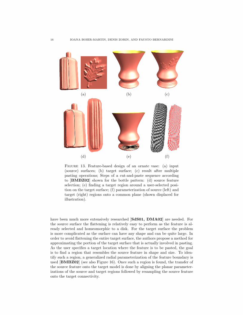
Biermann et al. [BMBZ02] describe a more general procedure for cutting andpasting portions of existing surfaces using an intuitive approach, similar to thosecommonly used for 2D image cut-and-paste. The user initiates a cutting operationby selecting a feature of interest on an existing surface (termed the source surface(see Figure 13 (a)). She also specifies a position on a target surface where thesource feature is to be pasted (see Figure 13 (b)). The actual pasting is performedin a sequence of steps (Figures 13(c)-(g)) which take advantage of the underlyingsemi-regular representation to achieve interactive rates. A discussion of the mainsteps follows.
Feature selection is performed interactively by the user who selects a regionof interest on the source surface. A free-form closed space curve is used to outlinethe selection. The portion of the surface inside the curve constitutes the feature(s)of interest. The curve can have an arbitrary shape and does not have to be alignedwith underlying mesh edges. The portion of the surface inside the curve must havedisk topology, but it does not have to be a height field (see Figure 14).
Base / detail separation must be performed on both the source and targetsurfaces to define what constitutes feature detail as opposed to the larger-scale sur-face shape that should be ignored. Since this is largely dependent on the semanticsof the operation, it is best left to the user. In [BMBZ02], the authors proposea continuum of base surface choices controlled by a flatness parameter. The basesurfaces are obtained by smoothing the original surface to various degrees or bysimple energy minimization within the feature boundary. Figure 15 illustrates thedifferent effects obtained using different base surfaces for the source and targetmodels.
Feature transfer is a complex process as it generally involves finding a map-ping between two arbitrary surfaces. The solution proposed in [BMBZ02] is tobuild the mapping as a composition of maps to an auxiliary plane. The advantageof this approach is that it no longer requires parameterizing an arbitrary (source)surface onto another arbitrary (target) surface. Instead, flattening methods which
16 IOANA BOIER-MARTIN, DENIS ZORIN, AND FAUSTO BERNARDINI
(a) (b) (c)
(d) (e) (f)
Figure 13. Feature-based design of an ornate vase: (a) input(source) surfaces; (b) target surface; (c) result after multiplepasting operations; Steps of a cut-and-paste sequence accordingto [BMBZ02] shown for the bottle pattern: (d) source featureselection; (e) finding a target region around a user-selected posi-tion on the target surface; (f) parameterization of source (left) andtarget (right) regions onto a common plane (shown displaced forillustration).
have been much more extensively researched [SdS01, DMA02] are needed. Forthe source surface the flattening is relatively easy to perform as the feature is al-ready selected and homeomorphic to a disk. For the target surface the problemis more complicated as the surface can have any shape and can be quite large. Inorder to avoid flattening the entire target surface, the authors propose a method forapproximating the portion of the target surface that is actually involved in pasting.As the user specifies a target location where the feature is to be pasted, the goalis to find a region that resembles the source feature in shape and size. To iden-tify such a region, a generalized radial parameterization of the feature boundary isused [BMBZ02] (see also Figure 16). Once such a region is found, the transfer ofthe source feature onto the target model is done by aligning the planar parameter-izations of the source and target regions followed by resampling the source featureonto the target connectivity.

A SURVEY OF SUBDIVISION-BASED TOOLS FOR SURFACE MODELING 17
Figure 14. Pasting and interactively placing a complex feature:a digitized model of a clay ear constitutes the feature to be pastedonto the mannequin head. The ear can be interactively scaled,rotated, and translated on the surface of the head.
The pasting method of Biermann et al. [BMBZ02] provides a robust andefficient pipeline for interactive surface pasting. Its main constraints are relatedto self-intersections that may appear when features are pasted onto highly curvedsurfaces and to topological constraints on the features that can be pasted (i.e.,only features with disk topology are handled). The former can be solved usinga hierarchical pasting approach, in which the feature to be pasted is decomposedinto frequency bands and the pasting is performed progressively, by pasting low-frequency details first, and high-frequency ones on top. The latter problem is morecomplex and requires more careful handling. A possible solution, albeit outside thesubdivision framework, has been recently proposed in [FMMY03]. In this case, avolumetric approach is used to parameterize the feature and B-spline fitting is usedto separate base from details. The advantage lies in the generality of features thatare handled, including higher genus ones and the ability to paste them on highlycurved areas. The main drawbacks are related to B-spline fitting and the need tointroduce a large number of points in order to obtain a good fit. The result is not aseamless representation, but rather a composite one consisting of the original andthe pasted part. In addition, the feature cannot be interactively dragged on thetarget surface.
3.2.3. Surface Trimming. Trimming, i.e., cutting holes in the surface of anobject along specified curves, can also be considered as an instance of a Boolean

18 IOANA BOIER-MARTIN, DENIS ZORIN, AND FAUSTO BERNARDINI
Figure 15. The effects of changing the base surface on the re-sult of pasting: (top) digitized bottle detail appears on the vasedifferently, depending on the choice of base surface; (bottom) thebutterfly feature is pasted on a rock model with and without preser-vation of target detail.
operation. Since this type of operation requires special subdivision rules along thetrim boundary, we classify it as a special case of a non-smooth feature and wediscuss it in section 3.3.
3.3. Non-Smooth Features. Subdivision surfaces can be naturally used tomodel smooth surfaces of arbitrary topological type. Many real objects, however,exhibit non-smooth features, such as sharp edges and boundaries, corners, anddarts. While multiresolution detail vectors may be used to approximate sharpfeatures (see Figure 17), a different setting is required to represent such featuresexactly. It entails altering the subdivision rules to produce limit surfaces that areonly piecewise smooth, i.e., consist of smooth patches joined together along possiblysharp boundaries. To represent piecewise smooth surfaces, control mesh edges andvertices are typically tagged for special handling (see Figure 18). Special subdivisionrules are employed in the vicinity of tagged mesh elements so as to avoid smoothingthem. An edge can be tagged as a crease edge and vertices incident to crease edgesmay be tagged as one of the following (see Figure 18):
• crease vertex: exactly two crease edges join smoothly at this vertex• corner vertex: two or more crease edges join non-smoothly at this vertex• dart vertex: exactly one crease edge is adjacent to this vertex
Early mention of special rules for surfaces with boundaries appeared in thework of Doo [Doo78] and Nasri [Nas91], however accompanied only by partialanalyses of the resulting surfaces. The first rules leading to provably C1-continuous

A SURVEY OF SUBDIVISION-BASED TOOLS FOR SURFACE MODELING 19
Figure 16. Finding a target region through radial parameteriza-tion of the feature outline.
smooth sharp
Figure 17. Multiresolution details are required to approximatesharp features using smooth surface representations (left three im-ages). A piecewise smooth surface representation (right) allowssharp features to be modeled with detail vectors.
surfaces were defined in [HDD+94] as a generalization of the Loop subdivisionrules [Loo87]. The analysis of the resulting surfaces can be found in [Sch96].As pointed out in [BLZ00], the rules introduced in [HDD+94] have two maindrawbacks: they are not suitable for modeling concave corners and the shape ofthe generated surface boundaries depends on the number of interior control pointsadjacent to each boundary point. The latter leads to undesirable gaps betweensurfaces joined along such a boundary. Both problems were handled by Biermann etal. [BLZ00] for the Loop [Loo87] and Catmull-Clark [CC78] subdivision schemes.

20 IOANA BOIER-MARTIN, DENIS ZORIN, AND FAUSTO BERNARDINI
Figure 18. Mesh tags corresponding to (from left to right):crease, dart, and corner sharp features.
Modifications are sometimes applied to subdivision rules to achieve differenteffects. For example, deRose et al. [DKT98] propose an edge sharpness parameters to vary sharpness along an edge and to allow for different degrees of sharpness.The parameter is used to blend between the positions psmooth of a control pointobtained with the smooth subdivision rules and a point psharp obtained with sharpsubdivision rules:
pnew = (1 − s)psmooth + spsharp, s ∈ [0, 1]Biermann et al. [BLZ00] propose a flatness parameter f and a normal mod-
ification. The flatness parameter control the speed at which control points in aneighborhood converge to the tangent plane. The subdivision rules are modified toblend between control point positions obtained without flatness modification andpoints in the tangent plane (p denotes the vector of control points in the neighbor-hood of a point,a0, a1, a2 are the limit position and tangents at that point, and xi
denote the right eigenvectors of the subdivision matrix):pnew = (1 − f)p + f(a0x
0 + a1x1 + a2x
2), f ∈ [0, 1]The normal modification is somewhat similar, in that it interpolates between
the control point position obtained without the modification and positions in aprescribed tangent plane (a normal n is prescribed through a pair of tangent vectorscomputed as a′
i = (ain)n):pnew = p + t((a′
1 − a1)x1 + (a′2 − a2)x2), t ∈ [0, 1]
Examples of sharp features modeled as proposed by Biermann et al. [BLZ00] areillustrated in Figure 19. A software library for piecewise smooth subdivision basedon these rules is freely available from [BZ99].
A generalization of the subdivision concept that accommodates sharp featureswas developed by Sederberg et al. [SZSS98]. By drawing an analogy betweenrecursive subdivision schemes and knot insertion for B-splines, the authors pro-pose non-uniform versions of the Doo-Sabin [Doo78] and Catmull-Clark [CC78]subdivision schemes (under the general denomination of non-uniform recursive sub-division surfaces or NURSS). Each edge in a non-uniform Catmull-Clark controlmesh (each control point in a Doo-Sabin mesh) is assigned a knot spacing. Whenall knot spacings are equal, the standard schemes are obtained. Two types of sub-division rules have to be considered for NURSS: the usual refinement scheme forthe geometric positions of control points and an additional refinement scheme for

A SURVEY OF SUBDIVISION-BASED TOOLS FOR SURFACE MODELING 21
knot spacings. Sharp features can be generated by setting certain knot spacings tozero.
The methods described so far require sharp features to be aligned with controlmesh edges. Moreover, they provide little control over the profile of the resultingfeatures. To address these limitations, Khodakovsky et al. [KS99] propose a curve-based feature editing approach. Feature curves are defined directly on the modelsurface through user interaction and can follow arbitrary paths, unconstrained bythe connectivity of the underlying mesh. Features are obtained by perturbing thesurface in the vicinity of feature curves. The curves can exist on multiple levels ofa subdivision hierarchy. At each level, perturbations are computed with respect tolocal frames, so any coarse level modifications of the surface are carried throughto finer levels. Several parameters are used to control the profile of a feature. Inparticular, sharp features can be obtained by specifying different normal directionsfor the profile on either side of the curve. This method brings forth a number ofsignificant contributions with respect to previous approaches: it takes advantageof the multiresolution setting to define features through detail vectors at differentlevels, it does not impose any restrictions on the location of the feature curveson the surface or on their topology (curves can intersect or self intersect), andvarying profiles allow both smooth and sharp features to be represented. Themain drawback is that it does not preserve the input representation: after editing,the result is no longer a pure multiresolution subdivision surface, but rather acombined representation, consisting of a surface and a curve. This means that othersubdivision-based tools that require as input a pure multireolution representationcannot be directly applied to the result of an editing operation performed with thismethod.
Figure 19. Sharp features generated with the rules proposedin [BLZ00]. From left to right: concave corner, convex corner,and smooth crease.
This problem is solved in [BMZB02] which uses the reparameterization ideadescribed in section 3.2.1 to align the parameterization of the surface with thefeature curves. Subsequently, sharp subdivision rules can be used along such curves.Figure 20 illustrates this process. An arbitrary feature curve is first projectedonto the control mesh at some subdivision level (typically a coarse level whichis subsequently refined). A piecewise linear approximation of the curve image inthe parametric domain is computed by alternating Snapping and Refinement stepssimilar to those of Algorithm 1. The Snapping step moves mesh vertices ontothe curve if they are sufficiently close, while the Refinement step subdivides the

22 IOANA BOIER-MARTIN, DENIS ZORIN, AND FAUSTO BERNARDINI
parameterization linearly. If c : [0, 1] → X denotes the image of a feature curve inthe parameter domain X of the goal is to reparameterize the domain X such thatc passes through the vertices of X . This reduces to finding a one-to-one mappingΠ : X → X which maps vertices of X to curve points: Π(vi) = c(ti), for somevertices v0, v1, . . . and curve parameters t0, t1, . . . . After a finite number ofiterations of snapping and refinement, the resulting curve [v0, v1, . . . ] is guaranteedto have the same topology as c and to follow along mesh edges (and / or diagonalsin the case of the Catmull-Clark scheme). After reparameterization, the inputsurface is resampled according to the new parameterization. Intuitively, this movesthe control mesh on the surface and places mesh vertices on the feature curve.Subsequently, the actual feature can be created by tagging the appropriate meshedges and applying sharp subdivision rules.
Figure 20. Reparameterization for approximating a featurecurve: quads in parameter domain are recursively split and ver-tices are snapped to the curve. After several subdivision steps thecurve is approximated by a sequence of vertices and follows alongquad edges or diagonals.
In the case of Catmull-Clark meshes, there is an additional complication: thefeature curve may pass through mesh diagonals after reparameterization (see Fig-ure 21) and the standard crease rules do not support this situation. Biermann etal. [BMZB02] introduce new subdivision rules to deal with creases along quad di-agonals. Sample results obtained with this method are shown in Figures 22. Notethat the output surface is a multiresolution subdivision surface which can be manip-ulated with other tools designed to operate on such a representation. In addition,the framework is suitable not only for creating interior sharp features with variousprofiles (e.g., engravings, embossings), but also to create boundaries, i.e., to trimthe input surface along the feature curves. An example of a trimmed surface isshown in Figure 22.
For completeness, we also mention the trimming method proposed by Litkeet al. [LLS01b] which is complementary to that of Biermann et al. [BMZB02].In this case quasi-interpolation is used to approximate a trimmed surface with acombined subdivision surface [Lev99].

A SURVEY OF SUBDIVISION-BASED TOOLS FOR SURFACE MODELING 23
Figure 21. Standard sharp rules do not cover cases when thesharp edge (thick line) passes through a quad diagonal. New rulesare necessary for such cases. Dotted lines and circles indicate ver-tices obtained by reflection used to define subdivision rules for suchcases (see [BMZB02] for details).
Figure 22. Surfaces obtained after trimming and embossing withsharp features using the method described in [BMZB02]. Top:input curves are shown on the surface (left) and projected intoparameter space (middle). The surface obtained is shown on theright. Bottom: a self-intersecting feature.
4. Conclusions
In this paper we presented an overview of subdivision-based tools for surface de-sign. We considered three major design categories: free-form deformations, Booleanoperations, and surface decorations with sharp features. Such tools have multiple

24 IOANA BOIER-MARTIN, DENIS ZORIN, AND FAUSTO BERNARDINI
applications to animated character creation, virtual reconstructions and restora-tions, industrial design, shape modeling for medical and scientific simulations, etc.While modeling with subdivision surfaces has received a significant boost in recentyears, there are a number of open issues still to be resolved. Among them arephysical validation and interactive collision detection, guaranteed error bounds forsurface fitting, and better integration between subdivision-based tools and methodsoperating on other representations.
References
[BAD+01] M. Boo, M. Amor, M. Doggett, J. Hirche, and Wolfgang Strasser, Hardware sup-port for adaptive subdivision surface rendering, Proceedings of the ACM SIG-GRAPH/EUROGRAPHICS Workshop on Graphics Hardware, 2001.
[Bar84] A. H. Barr, Global and local deformations of solid primitives, Proc. of SIGGRAPH84 (1984), 21–30.
[BBF94] C. Barghiel, R. Bartels, and D. Forsey, Pasting spline surfaces, Mathematical Methodsfor Curves and Surfaces: Ulvik, Norway, Vanderbilt University Press, 1994, Availableat ftp://cgl.uwaterloo.ca/pub/users/rhbartel/Paste.ps.gz, pp. 31–40.
[Bez74] P. Bezier, Mathematical and practical possibilities of UNISURF, CAD (1974), 127–152.
[BKS00] S. Bischoff, L. P. Kobbelt, and H.-P. Seidel, Towards hardware implementation of loopsubdivision, Proc. of the ACM SIGGRAPH/EUROGRAPHICS workshop on GraphicsHardware, 2000, pp. 41–50.
[BKZ01] H. Biermann, D. Kristjansson, and D. Zorin, Approximate boolean operations on free-form solids, Proceedings of SIGGRAPH 01, August 2001, pp. 185–194.
[BLZ00] H. Biermann, A. Levin, and D. Zorin, Piecewise smooth subdivision surfaces withnormal control, Proceedings of SIGGRAPH 00, 2000, pp. 113–120.
[BMBZ02] H. Biermann, I. Martin, F. Bernardini, and D. Zorin, Cut-and-paste editing of mul-tiresolution surfaces, ACM TOG. Special issue for SIGGRAPH conference 21 (2002),no. 3, 312–321.
[BMRB04] I. Boier-Martin, R. Ronfard, and F. Bernardini, Detail-preserving variational surfacedesign with multiresolution constraints, Proc. Shape Modeling International, SMI’04,2004.
[BMZB02] H. Biermann, I. Martin, D. Zorin, and F. Bernardini, Sharp features on multiresolu-tion subdivision surfaces, Graphical Models 64 (2002), no. 2, 61–77.
[Bri87] W. L. Briggs, Multigrid tutorial, SIAM, 1987.[BZ99] H. Biermann and D. Zorin, Subdivide 2.0 software, 1999.[cat] http://www.catia.ibm.com.[CC78] E. Catmull and J. Clark, Recursively generated B-spline surfaces on arbitrary topo-
logical meshes, CAD 10 (1978), no. 6, 350–355.[CG99] G. Celniker and D. Gossard, Energy-based models for free-form surface shape design,
Proc. ASME Design Automation Conference, 1999.[CM00] B. Conrad and S. Mann, Better pasting via quasi-interpolation, Curve and Surface
Design: Saint-Malo, 1999 (Nashville, TN) (P.-J. Laurent, P. Sablonniere, and L. L.Schumaker, eds.), Vanderbilt University Press, 2000, pp. 27–36.
[CMB97] L. K. Y. Chan, S. Mann, and R. Bartels, World space surface pasting, Proceedings ofGraphics Interface (W. Davis, M. Mantei, and V. Klassen, eds.), May 1997, pp. 146–154.
[Coq90] S. Coquillart, Extended free-form deformation: a sculpturing tool for 3d geometricmodeling, Proc. of SIGGRAPH 90, 1990, pp. 187–196.
[CR94] Y. Chang and A. P. Rockwood, A generalized de casteljau approach to 3D Free-Formdeformation, Proc. of SIGGRAPH 94 (1994), 257–260.
[CRE01] E. Cohen, R. F. Riesenfeld, and G. Elber, Geometric modeling with splines, A K
Peters Ltd, 2001.[CSA+02] F. Cirak, M.J. Scott, E.K. Antonson, M. Ortiz, and P. Schroder, Integrated mod-
eling, finite-element analysis, and engineering design for thin-shell structures usingsubdivision, Computer Aided Design 43 (2002), 137–148.

A SURVEY OF SUBDIVISION-BASED TOOLS FOR SURFACE MODELING 25
[CST94] M. M. Chang, M. I. Sezan, and A. M. Tekalp, Adaptive bayesian segmentation ofcolor images, Journal of Electronic Imaging 3 (1994), 404–414.
[dF73] C. deBoor and G. J. Fix, Spline approximtion by quasiinterpolants, Journal of Ap-proximation Theory 8 (1973), 19–45.
[DKT98] T. DeRose, M. Kass, and T. Truong, Subdivision surfaces in character animation,Proceedings of SIGGRAPH 98, 1998, pp. 85–94.
[DL02] N. Dyn and D. Levin, Subdivision schemes in geometric modelling, Acta Numerica11 (2002).
[DLG90] N. Dyn, D. Levin, and J. A. Gregory, A butterfly subdivision scheme for surfaceinterpolation with tension control, ACM TOG 9 (1990), no. 2, 160–169.
[DMA02] Mathieu Desbrun, Mark Meyer, and Pierre Alliez, Intrinsic parameterizations of sur-face meshes, Eurographics conference proceedings, 2002, pp. 209–218.
[DMR02] U. Diewald, S. Morigi, and M. Rumpf, A cascadic geometric filtering approach tosubdivision, CAGD 19 (2002), no. 9, 675 – 694.
[Doo78] D. Doo, A subdivision algorithm for smoothing down irregularly shaped polyhedrons,Proceedings on Interactive Techniques in Computer Aided Design (Bologna), 1978,pp. 157–165.
[DS78] D. Doo and M. Sabin, Analysis of the behaviour of recursive division surfaces nearextraordinary points, CAD 10 (1978), no. 6, 356–360.
[dsm] http://www.discreet.com.[FMMY03] Y. Furukawa, H. Masuda, K. T. Miura, and H. Yamato, Cut-and-paste editing based
on constrained b-spline volume fitting, Proceedings Computer Graphics International,2003.
[FMS03] I. Friedel, P. Mullen, and P. Schroder, Data-dependent fairing of subdivision surfacesn,Proc. of SM 03, 2003.
[GKSS02] I. Guskov, A. Khodakovsky, P. Schroder, and W. Sweldens, Hybrid meshes: Mul-tiresolution using regular and irregular refinement, Proc. Symp. Comp. Geom., 2002,pp. 264–272.
[GM97] S. F. F. Gibson and B. Mirtich, A survey of deformable modeling in computer graphics,Tech. Report TR-97-19, MERL, Cambridge, MA, 1997.
[GOP99] C. Gonzalez-Ochoa and J. Peters, Localized-hierarchy surface splines (less), Proc.Symp. on Interactive 3D Graphics, 1999, pp. 7–15.
[Gre94] G. Greiner, Surface construction based on variational principles, Wavelets, Imagesand Surface Fitting (P. J. Laurent, A. LeMehaute, and L. Schumaker, eds.), AKPeters, 1994, pp. 277–286.
[GS01] E. Grinspun and P. Schroder, Normal bounds for subdivision-surface interferencedetection, Proc. of IEEE Visualization 01, 2001.
[Hal96] M. A. Halstead, Efficient techniques for surface design using constrained optimiza-tion, Ph.D. thesis, Univ. of California at Berkeley, 1996.
[HDD+94] H. Hoppe, T. DeRose, T. Duchamp, M. Halstead, H. Jin, J. McDonald, J. Schweitzer,and W. Stuetzle, Piecewise smooth surface reconstruction, Computer Graphics Pro-ceedings, Annual Conference Series, ACM Siggraph, 1994, pp. 295–302.
[HKD93] M. Halstead, M. Kass, and T. DeRose, Efficient, fair interpolation using Catmull-Clark surfaces, Proc. SIGGRAPH 1993, 1993, pp. 35–44.
[HQ03] J. Hua and H. Qin, Free-Form deformations via sketching and manipulating scalarfields, Proc. ACM Symp. on Solid Modeling and Applications, 2003, pp. 328 – 333.
[Kob96a] L. Kobbelt, Interpolatory subdivision on openquadrilateral nets with arbitrary topol-ogy, Proc. of Eurographics 96, 1996, pp. 409–420.
[Kob96b] L. Kobbelt, A variational approach to subdivision, Comput. Aided Geom. Design 13(1996), no. 8, 743–761. MR 97j:65029
[Kob00] L. P. Kobbelt, Discrete fairing and variational subdivision for freeform surface design,The Visual Computer 16 (2000), no. 3-4, 142–150.
[KS99] A. Khodakovsky and P. Schroder, Fine level feature editing for subdivision surfaces,Proceedings of ACM Solid Modeling, 1999.
[LCJ94] F. Lazarus, S. Coquillart, and P. Jancene, Axial deformations: an intuitive deforma-tion technique, CAD 26 (1994), no. 8, 607–61.
[LDW97] M. Lounsbery, T. DeRose, and J. Warren, Multiresolution analysis for surfaces ofarbitrary topological type, ACM TOG 16 (1997), no. 1, 34–73.
26 IOANA BOIER-MARTIN, DENIS ZORIN, AND FAUSTO BERNARDINI
[Lev99] A. Levin, Interpolating nets of curves by smooth subdivision surfaces, Proc. of SIG-GRAPH 99 (1999), 57–64.
[LFKN03] S. Lanquetin, S. Foufou, H. Kheddouci, and M. Neveu, Computing subdivision surfaceintersection, Proc. WSCG ’03, 2003.
[Lin00] L. Linsen, Netbased modelling, Proc. SCCG ’00, 2000, pp. 259–266.[LLS01a] N. Litke, A. Levin, and P. Schroder, Fitting subdivision surfaces, Proc. of IEEE
Visualization 2001, October 2001, pp. 319–324.[LLS01b] N. Litke, A. Levin, and P. Schroder, Trimming for subdivision surfaces, Computer
Aided Geometric Design 18 (2001), no. 5, 463–481.[LMH00] A. Lee, H. Moreton, and H. Hoppe, Displaced subdivision surfaces, Proc. of SIG-
GRAPH 00, 2000, pp. 85–94.[Loo87] C. Loop, Smooth subdivision surfaces based on triangles, Master’s thesis, University
of Utah, Department of Mathematics, 1987.[Ma00] M. Ma, The direct manipulation of pasted surfaces, Master’s thesis, University
of Waterloo, Waterloo, Ontario, Canada N2L 3G1, 2000, Available on WWW asftp://cs-archive.uwaterloo.ca/cs-archive/CS-2000-15/.
[may] http://www.alias.com.[MJ96] R. MacCracken and K. I. Joy, Free-Form deformations with lattices of arbitrary topol-
ogy, Proc. of SIGGRAPH 96, 1996, pp. 181–188.
[MQ00] K.T. McDonnell and H. Qin, Dynamic sculpting and animation of Free-Form subdi-vision solids, Proc. of IEEE Computer Animation, 2000.
[MZ00] W. Ma and N. Zhao, Catmull-clark surface fitting for reverse engineering applications,Proceedings of Geometric Modeling and Processing, 2000, pp. 274–282.
[NA02] A. H. Nasri and A. Abbas, Designing Catmull-Clark subdivision surfaces with curveinterpolation constraints, Computers and Graphics (2002).
[Nas91] A. H. Nasri, Surface interpolation on irregular networks with normal conditions,CAGD 8 (1991), 89–96.
[Nas00] A. Nasri, Interpolating meshes of boundary intersecting curves by subdivision surfaces,The Visual Computer 16 (2000).
[PB00] D. Piponi and G. Borshukov, Seamless texture mapping of subdivision surfaces bymodel pelting and texture blending, Proceedings of SIGGRAPH 00, 2000, pp. 471–478.
[Pet00] Jorg Peters, Patching Catmull-Clark meshes, Proceedings of SIGGRAPH 00, 2000,pp. 255–258.
[PL97] K. Pulli and M. Lounsbery, Hierarchical editing and rendering of subdivision surfaces,Tech. Report UW-CSE-97-04-07, Dept. of CS&E, University of Washington, Seattle,WA, 1997.
[PR97] J. Peters and U. Reif, The simplest subdivision scheme for smoothing polyhedra, ACMTOG 16 (1997), no. 4.
[PS96] K. Pulli and M. Segal, Fast rendering of subdivision surfaces, Proc. EurographicsWorkshop on Rendering, 1996, pp. 61–70.
[QMV98] H. Qin, C. Mandal, and B. Vemuri, Dynamic Catmull-Clark subdivision surfaces,IEEE TVCG 4 (1998), no. 3, 215–229.
[QT96] H. Qin and D. Terzopoulos, D-NURBS: A physics based framework for geometricdesign, IEEE TVCG 2 (1996), no. 1, 85–96.
[Sab71] M. Sabin, Interrogation techniques for parametric surfaces, Advanced computergraphics - economics, techniques and applications (R. D. Parslow and R. E. Green,eds.), Plenum Press, 1971, pp. 1095–1118.
[Sab02] M. A. Sabin, Subdivision surfaces tutorial, SMI 02 (2002).[Sch96] J. E. Schweitzer, Analysis and application of subdivision surfaces, Ph.D. thesis, Uni-
versity of Washington, Seattle, 1996.[SDS96] E. J. Stollnitz, T. DeRose, and D. H. Salesin, Wavelets for computer graphics: theory
and applications, Morgan Kaufmann, 1996.[SdS01] A. Sheffer and E. de Sturler, Parameterization of faceted surfaces for meshing using
angle based flattening, Engineering with Computers 17(3) (2001), 326–337.[Sei98] R. Seidel, The nature and meaning of perturbations in geometric computing, Discrete
Computational Geometry 19 (1998), no. 1, 1–17.

A SURVEY OF SUBDIVISION-BASED TOOLS FOR SURFACE MODELING 27
[SF98] K. Singh and E. Fiume, Wires: A geometric deformation technique, Proc. of SIG-GRAPH 98, 1998, pp. 405–414.
[SP86] T. W. Sederberg and S. R. Parry, Free-form deformation of solid geometric models,Proc. of SIGGRAPH 86, 1986, pp. 151–160.
[Sta98] J. Stam, Exact evaluation of catmull-clark subdivision surfaces at arbitrary parametervalues, Proceedings of SIGGRAPH 98, July 1998, pp. 395–404.
[STKK99] H. Suzuki, S. Takeuchi, F. Kimura, and T. Kanai, Subdivision surface fitting to arange of points, Proc. Pacific Graphics, 1999.
[SWZ04] S. Schaeffer, J. Warren, and D. Zorin, Lofting curve networks using subdivision sur-faces, submitted (2004).
[SZSS98] T. W. Sederberg, J. Zheng, D. Sewell, and M. Sabin, Non-uniform recursive subdivi-sion surfaces, Proceedings of SIGGRAPH 98, 1998, pp. 387–394.
[Tak98] S. Takahashi, Variational design of curves and surfaces using multiresolution con-straints, The Visual Computer 14(5/6) (1998), 208–227.
[TF88] D. Terzopoulos and K. Fleischer, Modeling inelastic deformation: Viscoelasticity,plasticity, fracture, Proc. of SIGGRAPH ’88, 1988, pp. 269–278.
[TO02] G. Turk and J. O’Brien, Modelling with implicit surfaces that interpolate, ACM TOG21 (2002), no. 4, 855 – 873.
[TPBF87] D. Terzopoulos, J. Platt, A. Barr, and K. Fleischer, Elastically deformable models,
Proc. of SIGGRAPH 87, 1987, pp. 205–214.[TQ94] D. Terzopoulos and H. Qin, Dynamic NURBS with geometric constraints for inter-
active sculpting, ACM TOG 13 (1994), no. 2, 103–136.[WW92] W. Welch and A. Witkin, Variational surface modeling, Proceedings of SIGGRAPH
’92, vol. 26, 1992, pp. 157–166.[WW98] H. Weimer and J. Warren, Subdivision schemes for thin-plate splines, Proc. EURO-
GRAPHICS ’98 17 (1998), no. 3.[WW01] J. Warren and H. Weimer, Subdivision methods for geometric design: A constructive
approach, Morgan Kaufmann, 2001.[ZK02] D. Zorin and D. Kristjansson, Evaluation of piecewise smooth subdivision surfaces,
The Visual Computer 18 (2002), no. 5–6, 299 – 315.[ZSD+00] D. Zorin, P. Schroder, T. DeRose, L. Kobbelt, A. Levin, and W. Sweldens, Subdivision
for modeling and animation, SIGGRAPH’00 Course Notes, 2000.[ZSS96] D. Zorin, P. Schroder, and W. Sweldens, Interpolating subdivision for meshes with
arbitrary topology, Proc. of SIGGRAPH 96, August 1996, pp. 189–192.[ZSS97] D. Zorin, P. Schroder, and W. Sweldens, Interactive multiresolution mesh editing,
Proc. of SIGGRAPH 97, 1997, pp. 259–268.
Ioana Boier-Martin, IBM T. J. Watson Research Center, Hawthorne, NY 10532
E-mail address: [email protected]
Denis Zorin, Media Research Lab, New York University, New York, NY 10003
E-mail address: [email protected]
Fausto Bernardini, IBM T. J. Watson Research Center, Hawthorne, NY 10532
E-mail address: [email protected]