a. system overview pan-lug compression...
TRANSCRIPT

D2.1For technical assistance in the U.S., call 866-405-6654 (outside the U.S., see inside back cover for directory)
PAN-LUG™ COMPRESSION CONNECTORSPanduit® Pan-Lug ™ Compression Connectors provide permanent terminations for a variety of power and grounding applications, with innovation, highest reliability, and lowest installed cost.Panduit offers the first and only copper compression lugs and splices that meet Network Equipment-Building Systems (NEBS) Level 3 requirements as tested by Telcordia Technologies.NEBS Level 3 assures that product performance is suitable for equipment applications that demand minimal service interruptions over the life span of the equipment.
• Functional product information is marked directly on theconnector, facilitating the identification, ordering, andusage of the compression connector
• Color-coded to facilitate quick identification of the propercrimping die
• Made from high strength, high conductivity electrolyticcopper and aluminum alloy materials to provide optimumconnectivity for power and grounding applications
• UL Listed or Recognized, CSA Certified, ABS Type Approvedand tested by Telcordia – meets NEBS Level 3, as noted
• Terminations using Panduit ® Pan-Lug™ CompressionConnectors are also UL Listed and CSA Certified withspecified competitor tools
• Wide assortment of manual, controlled cycle, batteryoperated hydraulic and pneumatic crimping tools forreliable connections at the lowest installed cost
Panduit® Pan-Lug ™ Compression Connectors are designed for use with many different code and
flex conductor types and are available in a broad range of styles and sizes including copper
one-hole, two-hole, and blank tongue lugs and splices; aluminum one-hole and two-hole lugs and
splices; and copper in-line reducing splices. Panduit offers a wide assortment of Pan-Lug ™ Power
Connectors to meet customer needs and today’s application requirements.
ELECTRICAL SOLUTIONS
B2.Cable
Accessories
C1.Wiring
Duct
C3.Abrasion
Protection
C4.Cable
Management
D1.Terminals
D2.Power
Connectors
E1.LabelingSystems
E2.Labels
E3.Pre-Printed & Write-On
Markers
F.Index
B3.StainlessSteel Ties
C2.Surface
Raceway
E5.Lockout/Tagout
& SafetySolutions
B1.Cable Ties
A.System
Overview
D3.GroundingConnectors
E4.Permanent
Identification
Courtesy of Steven Engineering, Inc. - (800) 258-9200 - [email protected] - www.stevenengineering.com
D2.2
ELECTRICAL SOLUTIONS
B2.Cable
Accessories
C1.Wiring
Duct
C3.Abrasion
Protection
C4.Cable
Management
D1.Terminals
D2.Power
Connectors
E1.LabelingSystems
E2.Labels
E3.Pre-Printed & Write-On
Markers
F.Index
B3.StainlessSteel Ties
C2.Surface
Raceway
E5.Lockout/Tagout
& SafetySolutions
B1.Cable Ties
A.System
Overview
D3.GroundingConnectors
E4.Permanent
Identification
Factory pre-filledwith oxide inhibitorto prevent oxidation
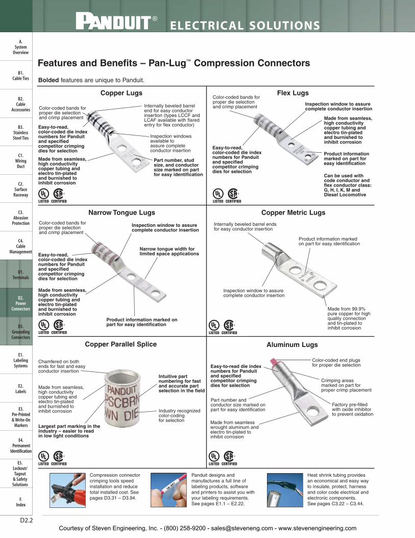
Features and Benefits – Pan-Lug™ Compression Connectors
Copper Lugs
Copper Parallel Splice Aluminum Lugs
Copper Metric Lugs
Part number and conductor size marked onpart for easy identification
Largest part marking in theindustry – easier to read in low light conditions
Easy-to-read die indexnumbers for Panduitand specifiedcompetitor crimpingdies for selection
Color-coded end plugs for proper die selection
Crimping areasmarked on part forproper crimp placement
Made from seamlesswrought aluminum andelectro tin-plated toinhibit corrosion
Can be used withcode conductor andflex conductor class:G, H, I, K, M andDiesel Locomotive
Bolded features are unique to Panduit.
Compression connectorcrimping tools speedinstallation and reducetotal installed cost. Seepages D3.31 – D3.94.
Panduit designs andmanufactures a full line oflabeling products, softwareand printers to assist you withyour labeling requirements.See pages E1.1 – E2.22.
Heat shrink tubing providesan economical and easy wayto insulate, protect, harnessand color code electrical andelectronic components.See pages C3.22 – C3.44.
Chamfered on both ends for fast and easy conductor insertion
Made from seamless,high conductivity copper tubing and electro tin-plated and burnished to inhibit corrosion Industry recognized
color-coding for selection
Intuitive part numbering for fastand accurate partselection in the field
Flex Lugs
Narrow Tongue Lugs
Color-coded bands forproper die selectionand crimp placement
Color-coded bands forproper die selectionand crimp placement
Color-coded bands forproper die selectionand crimp placement
Inspection windowsavailable toassure completeconductor insertion
Part number, studsize, and conductorsize marked on partfor easy identification
Easy-to-read,color-coded die indexnumbers for Panduitand specified competitor crimping dies for selection
Easy-to-read,color-coded die indexnumbers for Panduitand specified competitor crimping dies for selection
Internally beveled barrelend for easy conductorinsertion (types LCCF andLCAF available with flaredentry for flex conductor)
Made from seamless,high conductivity copper tubing andelectro tin-plated and burnished to inhibit corrosion
Easy-to-read,color-coded die indexnumbers for Panduitand specified competitor crimping dies for selection
Made from seamless,high conductivity copper tubing andelectro tin-plated and burnished to inhibit corrosion
Made from seamless,high conductivity copper tubing andelectro tin-plated and burnished to inhibit corrosion
Product information marked on part for easy identification
Inspection window to assurecomplete conductor insertion
Product information marked on part for easy identification
Internally beveled barrel endsfor easy conductor insertion
Made from 99.9%pure copper for highquality connectionand tin-plated toinhibit corrosion
Inspection window to assurecomplete conductor insertion
Inspection window to assurecomplete conductor insertion
Product information marked onpart for easy identification
Narrow tongue width for limited space applications
Courtesy of Steven Engineering, Inc. - (800) 258-9200 - [email protected] - www.stevenengineering.com

D2.3For technical assistance in the U.S., call 866-405-6654 (outside the U.S., see inside back cover for directory)
ELECTRICAL SOLUTIONS
B2.Cable
Accessories
C1.Wiring
Duct
C3.Abrasion
Protection
C4.Cable
Management
D1.Terminals
D2.Power
Connectors
E1.LabelingSystems
E2.Labels
E3.Pre-Printed & Write-On
Markers
F.Index
B3.StainlessSteel Ties
C2.Surface
Raceway
E5.Lockout/Tagout
& SafetySolutions
B1.Cable Ties
A.System
Overview
D3.GroundingConnectors
E4.Permanent
Identification
Selection Guide – Pan-Lug™ Copper Compression Connectors for Copper Code Conductor
Short Barrel
Butt Splices
T Splices
Parallel Splices
SCSS Pg.
LCD D2.31, D2.32LCD-H 45° bent D2.33, D2.34LCD-F 90° bent D2.35, D2.36LCDN narrow tongue D2.37LCDN-H 45° bent narrow tongue D2.38LCDN-F 90° bent narrow tongue D2.39LCD-00 blank tongue D2.40
LCAS D2.7, D2.8LCAS-H 45° bent D2.9, D2.10LCAS-F 90° bent D2.11, D2.12
LCA D2.13, D2.14LCA-H 45° bent D2.15, D2.16LCA-F 90° bent D2.17, D2.18LCAN narrow tongue D2.19, D2.20LCA-00 blank tongue D2.21
LCB D2.22, D2.23LCB-H 45° bent D2.24, D2.25LCB-F 90° bent D2.26, D2.27LCBH with corona relief taper D2.30
LCC D2.41, D2.42LCC-H 45° bent D2.43, D2.44LCC-F 90° bent D2.45, D2.46LCCH with corona relief taper D2.56LCC-00 blank tongue D2.57
LCB-W D2.28LCB-WH 45° bent D2.29LCB-WF 90° bent D2.29
LCC-W D2.47, D2.48, D2.49LCC-WH 45° bent D2.50, D2.51, D2.52LCC-WF 90° bent D2.53, D2.54, D2.55LCCN-W narrow tongue D2.55LCC-00W blank tongue D2.58
SCSS D2.59
SCS D2.60
SCL D2.61SCH with corona relief chamfer D2.62
PSC D2.64
SCT D2.63
Short Barrel withInspection Window
Long Barrel noInspection Window
Long Barrel withInspection Window
Standard Barrel
Long Barrel
Long Barrel noInspection Window
One-Hole Lugs
Two-Hole Lugs
Standard Barrel withInspection Window
Long Barrel withInspection Window
Standard Barrel withInspection Window
Code
Connector Barrel Style Type Page Number
One-Hole Metric Lugs
LCMA D2.107, D2.108
Metric Splices SCMS D2.111
Two-Hole Metric Lugs
LCMD D2.109, D2.110
Courtesy of Steven Engineering, Inc. - (800) 258-9200 - [email protected] - www.stevenengineering.com

D2.4
ELECTRICAL SOLUTIONS
B2.Cable
Accessories
C1.Wiring
Duct
C3.Abrasion
Protection
C4.Cable
Management
D1.Terminals
D2.Power
Connectors
E1.LabelingSystems
E2.Labels
E3.Pre-Printed & Write-On
Markers
F.Index
B3.StainlessSteel Ties
C2.Surface
Raceway
E5.Lockout/Tagout
& SafetySolutions
B1.Cable Ties
A.System
Overview
D3.GroundingConnectors
E4.Permanent
Identification
LCAX D2.66, D2.67LCAX-H 45° bent D2.68, D2.69LCAX-F 90° bent D2.70, D2.71LCAXN narrow tongue D2.72
LCAF D2.73, D2.74LCAF-H 45° bent D2.75, D2.76LCAF-F 90° bent D2.77, D2.78
Two-Hole Lugs
Selection Guide – Pan-Lug™ Copper Compression Connectors for Copper Code and/or Flex Conductor
One-Hole Lugs
Long Barrel withInspection Window
Code and Flex
Standard Barrel withInspection Window
Code and Flex
Standard Barrel with Inspection
Window and Flared Entry Flex
Long Barrel withInspection Window
Code and Flex
Reducing Spliceswith Inspection
Window forCode and Flex
LCDX D2.82, D2.83LCDX-H 45° bent D2.84, D2.85LCDX-F 90° bent D2.86, D2.87LCDXN narrow tongue D2.88LCDXN-H 45° bent narrow tongue D2.89LCDXN-F 90° bent narrow tongue D2.89
LCCF D2.96, D2.97LCCF-H 45° bent D2.98, D2.99LCCF-F 90° bent D2.100, D2.101
LCBX D2.79LCBX-H 45° bent D2.80LCBX-F 90° bent D2.81
LCCX D2.90, D2.91LCCX-H 45° bent D2.92, D2.93LCCX-F 90° bent D2.94, D2.95LCCXN narrow tongue D2.95
RSCK kits with reducing splice and clear heat shrink D2.103, D2.104RSC reducing splices D2.105, D2.106
SCSF D2.102
Long Barrel noInspection WindowFlared Entry Flex
Standard Barrel withInspection Window
Code and Flex
Butt Spliceswith Flared
Entry for Flex
Code Flex
Connector Barrel Style Type Page Number
Courtesy of Steven Engineering, Inc. - (800) 258-9200 - [email protected] - www.stevenengineering.com
D2.5For technical assistance in the U.S., call 866-405-6654 (outside the U.S., see inside back cover for directory)
ELECTRICAL SOLUTIONS
B2.Cable
Accessories
C1.Wiring
Duct
C3.Abrasion
Protection
C4.Cable
Management
D1.Terminals
D2.Power
Connectors
E1.LabelingSystems
E2.Labels
E3.Pre-Printed & Write-On
Markers
F.Index
B3.StainlessSteel Ties
C2.Surface
Raceway
E5.Lockout/Tagout
& SafetySolutions
B1.Cable Ties
A.System
Overview
D3.GroundingConnectors
E4.Permanent
Identification
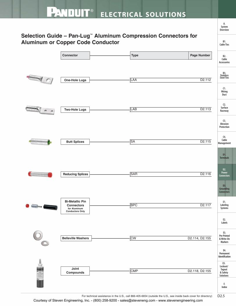
Selection Guide – Pan-Lug™ Aluminum Compression Connectors forAluminum or Copper Code Conductor
One-Hole Lugs
Two-Hole Lugs
Butt Splices
Reducing Splices
Bi-Metallic PinConnectorsfor Aluminum
Conductors Only
JointCompounds
Belleville Washers
LAA D2.112
LAB D2.113
SA D2.115
SAR D2.116
BPC D2.117
CW D2.114, D2.155
CMP D2.118, D2.155
Type Page NumberConnector
Courtesy of Steven Engineering, Inc. - (800) 258-9200 - [email protected] - www.stevenengineering.com

D2.6
ELECTRICAL SOLUTIONS
Prime items appear in BOLD.
B2.Cable
Accessories
C1.Wiring
Duct
C3.Abrasion
Protection
C4.Cable
Management
D1.Terminals
D2.Power
Connectors
E1.LabelingSystems
E2.Labels
E3.Pre-Printed & Write-On
Markers
F.Index
B3.StainlessSteel Ties
C2.Surface
Raceway
E5.Lockout/Tagout
& SafetySolutions
B1.Cable Ties
A.System
Overview
D3.GroundingConnectors
E4.Permanent
Identification
Part Number System for Pan-Lug ™ Compression AWG Lugs
2/0 — —38 D F X
ConductorSize
Stud Hole Size
Two Stud Hole Spacing
Tongue Angle
LCD
Type
10 = #10
14 = 1/4"
56 = 5/16"
38 = 3/8"
12 = 1/2"
58 = 5/8"
34 = 3/4"
78 = 7/8"
00 = Blank Tongue*
1 = 1
2 = 2
3 = 3
5 = 5
6 = 6
X = 10
E = 20
Q = 25
L = 50
A = .625"
B = .750"
C = .875"
D = 1.0"
E = 1.25"
G = 1.5"
J = .5"
K = 2"
M = 1.375"
P = .688"
Q = 1.125"
No Letter = 1.75"
H = 45° Angle
F = 90° Angle
No Letter = Straight
Ex: LCD Lug, Copper Two-Hole Standard Barrel
* LCA, LCCand LCD styles only
Standard Package Size
Courtesy of Steven Engineering, Inc. - (800) 258-9200 - [email protected] - www.stevenengineering.com

D2.7For technical assistance in the U.S., call 866-405-6654 (outside the U.S., see inside back cover for directory)
ELECTRICAL SOLUTIONS
B2.Cable
Accessories
C1.Wiring
Duct
C3.Abrasion
Protection
C4.Cable
Management
D1.Terminals
D2.Power
Connectors
E1.LabelingSystems
E2.Labels
E3.Pre-Printed & Write-On
Markers
F.Index
B3.StainlessSteel Ties
C2.Surface
Raceway
E5.Lockout/Tagout
& SafetySolutions
B1.Cable Ties
A.System
Overview
D3.GroundingConnectors
E4.Permanent
Identification
Code Conductor, One-Hole, Short Barrel with Window Lug
• Short barrel for limited space applications
• Color-coded barrels marked with Panduit and specified competitordie index numbers for proper crimp die selection
• Inspection window to visually assure full conductor insertion
• Tin-plated to inhibit corrosion
• UL Listed and CSA Certified to 35 KV** and temperature rated to90°C when crimped with Panduit and specified competitorcrimping tools and dies
• Tested by Telcordia – meets NEBS Level 3
• American Bureau of Shipping approved
Type LCAS
For Use with Stranded Copper Conductors
W
L
INSPECTIONWINDOW
T
B
‡See pages D3.56, D3.57 for tool and die information.**Consult cable manufacturer for voltage stress relief instructions with applications greater than 2000 V.
Table continues on page D2.8
Part Number
CopperConductor
Size
Stud HoleSize(In.)
Figure Dimensions (In.)
PanduitColorCode
PanduitDie Index
No.‡
Burndy Die Index
No.‡
T&B Die Index
No.‡
Wire StripLength
(In.)
Std.Pkg.Qty.W B T L
LCAS8-10-L
#8 AWG
#10 0.41 0.42 0.08 1.11 Red P21 49 21 1/2 50
LCAS8-14-L 1/4 0.48 0.42 0.07 1.20 Red P21 49 21 1/2 50
LCAS8-56-L 5/16 0.56 0.42 0.05 1.32 Red P21 49 21 1/2 50
LCAS8-38-L 3/8 0.60 0.42 0.05 1.42 Red P21 49 21 1/2 50
LCAS6-10-L
#6 AWG
#10 0.45 0.48 0.09 1.19 Blue P24 7 24 9/16 50
LCAS6-14-L 1/4 0.48 0.48 0.08 1.28 Blue P24 7 24 9/16 50
LCAS6-56-L 5/16 0.56 0.48 0.07 1.40 Blue P24 7 24 9/16 50
LCAS6-38-L 3/8 0.62 0.48 0.06 1.50 Blue P24 7 24 9/16 50
LCAS4-10-L
#4 AWG
#10 0.55 0.53 0.09 1.26 Gray P29 8 29 5/8 50
LCAS4-14-L 1/4 0.55 0.53 0.09 1.35 Gray P29 8 29 5/8 50
LCAS4-56-L 5/16 0.55 0.53 0.09 1.47 Gray P29 8 29 5/8 50
LCAS4-38-L 3/8 0.62 0.53 0.07 1.57 Gray P29 8 29 5/8 50
LCAS2-14-Q
#2 AWG
1/4 0.60 0.57 0.10 1.46 Brown P33 10 33 5/8 25
LCAS2-56-Q 5/16 0.66 0.57 0.10 1.58 Brown P33 10 33 5/8 25
LCAS2-38-Q 3/8 0.66 0.57 0.10 1.66 Brown P33 10 33 5/8 25
LCAS2-12-Q 1/2 0.75 0.57 0.08 1.89 Brown P33 10 33 5/8 25
LCAS1-14-E
#1 AWG
1/4 0.70 0.59 0.11 1.50 Green P37 11 37 11/16 20
LCAS1-56-E 5/16 0.70 0.59 0.11 1.63 Green P37 11 37 11/16 20
LCAS1-38-E 3/8 0.70 0.59 0.11 1.70 Green P37 11 37 11/16 20
LCAS1-12-E 1/2 0.75 0.59 0.09 1.94 Green P37 11 37 11/16 20
LCAS1/0-14-X
1/0 AWG
1/4 0.76 0.66 0.12 1.67 Pink P42 12 42 3/4 10
LCAS1/0-56-X 5/16 0.76 0.66 0.12 1.72 Pink P42 12 42 3/4 10
LCAS1/0-38-X 3/8 0.76 0.66 0.12 1.80 Pink P42 12 42 3/4 10
LCAS1/0-12-X 1/2 0.80 0.66 0.12 2.03 Pink P42 12 42 3/4 10
LCAS2/0-14-X
2/0 AWG
1/4 0.85 0.72 0.13 1.82 Black P45 13 45 3/4 10
LCAS2/0-56-X 5/16 0.85 0.72 0.13 1.82 Black P45 13 45 3/4 10
LCAS2/0-38-X 3/8 0.85 0.72 0.13 1.89 Black P45 13 45 3/4 10
LCAS2/0-12-X 1/2 0.85 0.72 0.13 2.14 Black P45 13 45 3/4 10
Courtesy of Steven Engineering, Inc. - (800) 258-9200 - [email protected] - www.stevenengineering.com

D2.8
ELECTRICAL SOLUTIONS
Prime items appear in BOLD.
B2.Cable
Accessories
C1.Wiring
Duct
C3.Abrasion
Protection
C4.Cable
Management
D1.Terminals
D2.Power
Connectors
E1.LabelingSystems
E2.Labels
E3.Pre-Printed & Write-On
Markers
F.Index
B3.StainlessSteel Ties
C2.Surface
Raceway
E5.Lockout/Tagout
& SafetySolutions
B1.Cable Ties
A.System
Overview
D3.GroundingConnectors
E4.Permanent
Identification
‡See pages D3.56, D3.57 for tool and die information.**Consult cable manufacturer for voltage stress relief instructions with applications greater than 2000 V.
Code Conductor, One-Hole, Short Barrel with Window Lug (continued)
LTBW
Std.Pkg.Qty.
Wire StripLength
(In.)
T&B Die Index
No.‡
Burndy Die Index
No.‡
PanduitDie Index
No.‡
PanduitColorCode
Figure Dimensions (In.)
Stud HoleSize(In.)
CopperConductor
SizePart NumberLCAS3/0-14-X
3/0 AWG
1/4 0.96 0.83 0.13 1.97 Orange P50 14 50 7/8 10
LCAS3/0-56-X 5/16 0.96 0.83 0.13 1.97 Orange P50 14 50 7/8 10
LCAS3/0-38-X 3/8 0.96 0.83 0.13 2.03 Orange P50 14 50 7/8 10
LCAS3/0-12-X 1/2 0.96 0.83 0.13 2.28 Orange P50 14 50 7/8 10
LCAS4/0-14-X
4/0 AWG
1/4 1.06 0.91 0.14 2.08 Purple P54 15 54 1 10
LCAS4/0-56-X 5/16 1.06 0.91 0.14 2.10 Purple P54 15 54 1 10
LCAS4/0-38-X 3/8 1.06 0.91 0.14 2.17 Purple P54 15 54 1 10
LCAS4/0-12-X 1/2 1.06 0.91 0.14 2.40 Purple P54 15 54 1 10
LCAS250-14-X
250 kcmil
1/4 1.17 1.03 0.14 2.25 Yellow P62 16 62 1 1/8 10
LCAS250-56-X 5/16 1.17 1.03 0.14 2.25 Yellow P62 16 62 1 1/8 10
LCAS250-38-X 3/8 1.17 1.03 0.14 2.32 Yellow P62 16 62 1 1/8 10
LCAS250-12-X 1/2 1.17 1.03 0.14 2.56 Yellow P62 16 62 1 1/8 10
Courtesy of Steven Engineering, Inc. - (800) 258-9200 - [email protected] - www.stevenengineering.com

D2.9For technical assistance in the U.S., call 866-405-6654 (outside the U.S., see inside back cover for directory)
ELECTRICAL SOLUTIONS
B2.Cable
Accessories
C1.Wiring
Duct
C3.Abrasion
Protection
C4.Cable
Management
D1.Terminals
D2.Power
Connectors
E1.LabelingSystems
E2.Labels
E3.Pre-Printed & Write-On
Markers
F.Index
B3.StainlessSteel Ties
C2.Surface
Raceway
E5.Lockout/Tagout
& SafetySolutions
B1.Cable Ties
A.System
Overview
D3.GroundingConnectors
E4.Permanent
Identification
Code Conductor, One-Hole, Short Barrel with Window Lug, 45° Angle
• Short barrel for limited space applications
• Color-coded barrels marked with Panduit and specified competitordie index numbers for proper crimp die selection
• Inspection window to visually assure full conductor insertion
• Tin-plated to inhibit corrosion
• UL Listed and CSA Certified to 35 KV** and temperature rated to90°C when crimped with Panduit and specified competitor crimpingtools and dies
• Tested by Telcordia – meets NEBS Level 3
• American Bureau of Shipping approved
For Use with Stranded Copper Conductors
Type LCAS-H
W
T
L
INSPECTIONWINDOW
B
45˚
‡See pages D3.56, D3.57 for tool and die information.**Consult cable manufacturer for voltage stress relief instructions with applications greater than 2000 V.
Table continues on page D2.10
Part Number
CopperConductor
Size
Stud HoleSize(In.)
Figure Dimensions (In.) Panduit
Color Code
Panduit Die Index
No.‡
Burndy Die Index
No.‡
T&B Die Index
No.‡
Wire StripLength
(In.)
Std.Pkg.Qty.W B T L
LCAS8-10H-L
#8 AWG
#10 0.41 0.42 0.08 1.00 Red P21 49 21 1/2 50
LCAS8-14H-L 1/4 0.48 0.42 0.07 1.09 Red P21 49 21 1/2 50
LCAS8-56H-L 5/16 0.56 0.42 0.05 1.20 Red P21 49 21 1/2 50
LCAS8-38H-L 3/8 0.60 0.42 0.05 1.30 Red P21 49 21 1/2 50
LCAS6-10H-L
#6 AWG
#10 0.45 0.48 0.09 1.06 Blue P24 7 24 9/16 50
LCAS6-14H-L 1/4 0.48 0.48 0.08 1.14 Blue P24 7 24 9/16 50
LCAS6-56H-L 5/16 0.56 0.48 0.07 1.26 Blue P24 7 24 9/16 50
LCAS6-38H-L 3/8 0.62 0.48 0.06 1.35 Blue P24 7 24 9/16 50
LCAS4-10H-L
#4 AWG
#10 0.55 0.53 0.09 1.12 Gray P29 8 29 5/8 50
LCAS4-14H-L 1/4 0.55 0.53 0.09 1.21 Gray P29 8 29 5/8 50
LCAS4-56H-L 5/16 0.55 0.53 0.09 1.33 Gray P29 8 29 5/8 50
LCAS4-38H-L 3/8 0.62 0.53 0.07 1.42 Gray P29 8 29 5/8 50
LCAS2-14H-Q
#2 AWG
1/4 0.60 0.57 0.10 1.27 Brown P33 10 33 5/8 25
LCAS2-56H-Q 5/16 0.66 0.57 0.10 1.39 Brown P33 10 33 5/8 25
LCAS2-38H-Q 3/8 0.66 0.57 0.10 1.46 Brown P33 10 33 5/8 25
LCAS2-12H-Q 1/2 0.75 0.57 0.08 1.68 Brown P33 10 33 5/8 25
LCAS1-14H-E
#1 AWG
1/4 0.70 0.59 0.11 1.29 Green P37 11 37 11/16 20
LCAS1-56H-E 5/16 0.70 0.59 0.11 1.42 Green P37 11 37 11/16 20
LCAS1-38H-E 3/8 0.70 0.59 0.11 1.49 Green P37 11 37 11/16 20
LCAS1-12H-E 1/2 0.75 0.59 0.09 1.73 Green P37 11 37 11/16 20
LCAS1/0-14H-X
1/0 AWG
1/4 0.76 0.66 0.12 1.43 Pink P42 12 42 3/4 10
LCAS1/0-56H-X 5/16 0.76 0.66 0.12 1.49 Pink P42 12 42 3/4 10
LCAS1/0-38H-X 3/8 0.76 0.66 0.12 1.56 Pink P42 12 42 3/4 10
LCAS1/0-12H-X 1/2 0.80 0.66 0.12 1.79 Pink P42 12 42 3/4 10
LCAS2/0-14H-X
2/0 AWG
1/4 0.85 0.72 0.13 1.58 Black P45 13 45 3/4 10
LCAS2/0-56H-X 5/16 0.85 0.72 0.13 1.58 Black P45 13 45 3/4 10
LCAS2/0-38H-X 3/8 0.85 0.72 0.13 1.64 Black P45 13 45 3/4 10
LCAS2/0-12H-X 1/2 0.85 0.72 0.13 1.89 Black P45 13 45 3/4 10
Courtesy of Steven Engineering, Inc. - (800) 258-9200 - [email protected] - www.stevenengineering.com

D2.10
ELECTRICAL SOLUTIONS
Prime items appear in BOLD.
B2.Cable
Accessories
C1.Wiring
Duct
C3.Abrasion
Protection
C4.Cable
Management
D1.Terminals
D2.Power
Connectors
E1.LabelingSystems
E2.Labels
E3.Pre-Printed & Write-On
Markers
F.Index
B3.StainlessSteel Ties
C2.Surface
Raceway
E5.Lockout/Tagout
& SafetySolutions
B1.Cable Ties
A.System
Overview
D3.GroundingConnectors
E4.Permanent
Identification
‡See pages D3.56, D3.57 for tool and die information.**Consult cable manufacturer for voltage stress relief instructions with applications greater than 2000 V.
Code Conductor, One-Hole, Short Barrel with Window Lug, 45° Angle(continued)
LTBW
Std.Pkg.Qty.
Wire StripLength
(In.)
T&B Die Index
No.‡
Burndy Die Index
No.‡
Panduit Die Index
No.‡Panduit
Color Code
Figure Dimensions (In.)
Stud HoleSize(In.)
CopperConductor
SizePart NumberLCAS3/0-14H-X
3/0 AWG
1/4 0.96 0.83 0.13 1.68 Orange P50 14 50 7/8 10
LCAS3/0-56H-X 5/16 0.96 0.83 0.13 1.68 Orange P50 14 50 7/8 10
LCAS3/0-38H-X 3/8 0.96 0.83 0.13 1.74 Orange P50 14 50 7/8 10
LCAS3/0-12H-X 1/2 0.96 0.83 0.13 1.99 Orange P50 14 50 7/8 10
LCAS4/0-14H-X
4/0 AWG
1/4 1.06 0.91 0.14 1.77 Purple P54 15 54 1 10
LCAS4/0-56H-X 5/16 1.06 0.91 0.14 1.78 Purple P54 15 54 1 10
LCAS4/0-38H-X 3/8 1.06 0.91 0.14 1.85 Purple P54 15 54 1 10
LCAS4/0-12H-X 1/2 1.06 0.91 0.14 2.08 Purple P54 15 54 1 10
LCAS250-14H-X
250 kcmil
1/4 1.17 1.03 0.14 1.89 Yellow P62 16 62 1 1/8 10
LCAS250-56H-X 5/16 1.17 1.03 0.14 1.90 Yellow P62 16 62 1 1/8 10
LCAS250-38H-X 3/8 1.17 1.03 0.14 1.97 Yellow P62 16 62 1 1/8 10
LCAS250-12H-X 1/2 1.17 1.03 0.14 2.20 Yellow P62 16 62 1 1/8 10
Courtesy of Steven Engineering, Inc. - (800) 258-9200 - [email protected] - www.stevenengineering.com
D2.11For technical assistance in the U.S., call 866-405-6654 (outside the U.S., see inside back cover for directory)
ELECTRICAL SOLUTIONS
B2.Cable
Accessories
C1.Wiring
Duct
C3.Abrasion
Protection
C4.Cable
Management
D1.Terminals
D2.Power
Connectors
E1.LabelingSystems
E2.Labels
E3.Pre-Printed & Write-On
Markers
F.Index
B3.StainlessSteel Ties
C2.Surface
Raceway
E5.Lockout/Tagout
& SafetySolutions
B1.Cable Ties
A.System
Overview
D3.GroundingConnectors
E4.Permanent
Identification
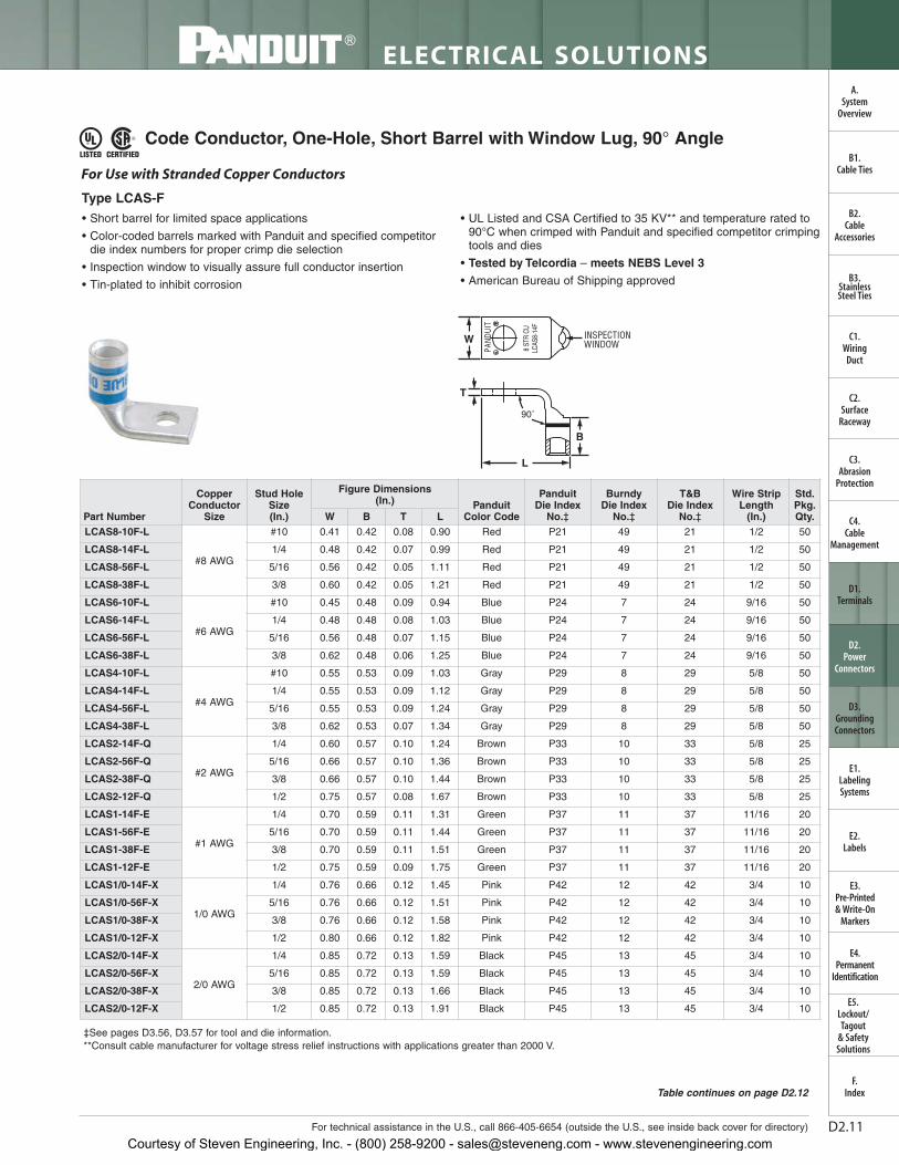
Code Conductor, One-Hole, Short Barrel with Window Lug, 90° Angle
• Short barrel for limited space applications
• Color-coded barrels marked with Panduit and specified competitordie index numbers for proper crimp die selection
• Inspection window to visually assure full conductor insertion
• Tin-plated to inhibit corrosion
• UL Listed and CSA Certified to 35 KV** and temperature rated to90°C when crimped with Panduit and specified competitor crimpingtools and dies
• Tested by Telcordia – meets NEBS Level 3
• American Bureau of Shipping approved
For Use with Stranded Copper Conductors
Type LCAS-F
W INSPECTIONWINDOW
T
L
90˚
B
‡See pages D3.56, D3.57 for tool and die information.**Consult cable manufacturer for voltage stress relief instructions with applications greater than 2000 V.
Table continues on page D2.12
Part Number
CopperConductor
Size
Stud HoleSize(In.)
Figure Dimensions (In.) Panduit
Color Code
Panduit Die Index
No.‡
Burndy Die Index
No.‡
T&B Die Index
No.‡
Wire StripLength
(In.)
Std.Pkg.Qty.W B T L
LCAS8-10F-L
#8 AWG
#10 0.41 0.42 0.08 0.90 Red P21 49 21 1/2 50
LCAS8-14F-L 1/4 0.48 0.42 0.07 0.99 Red P21 49 21 1/2 50
LCAS8-56F-L 5/16 0.56 0.42 0.05 1.11 Red P21 49 21 1/2 50
LCAS8-38F-L 3/8 0.60 0.42 0.05 1.21 Red P21 49 21 1/2 50
LCAS6-10F-L
#6 AWG
#10 0.45 0.48 0.09 0.94 Blue P24 7 24 9/16 50
LCAS6-14F-L 1/4 0.48 0.48 0.08 1.03 Blue P24 7 24 9/16 50
LCAS6-56F-L 5/16 0.56 0.48 0.07 1.15 Blue P24 7 24 9/16 50
LCAS6-38F-L 3/8 0.62 0.48 0.06 1.25 Blue P24 7 24 9/16 50
LCAS4-10F-L
#4 AWG
#10 0.55 0.53 0.09 1.03 Gray P29 8 29 5/8 50
LCAS4-14F-L 1/4 0.55 0.53 0.09 1.12 Gray P29 8 29 5/8 50
LCAS4-56F-L 5/16 0.55 0.53 0.09 1.24 Gray P29 8 29 5/8 50
LCAS4-38F-L 3/8 0.62 0.53 0.07 1.34 Gray P29 8 29 5/8 50
LCAS2-14F-Q
#2 AWG
1/4 0.60 0.57 0.10 1.24 Brown P33 10 33 5/8 25
LCAS2-56F-Q 5/16 0.66 0.57 0.10 1.36 Brown P33 10 33 5/8 25
LCAS2-38F-Q 3/8 0.66 0.57 0.10 1.44 Brown P33 10 33 5/8 25
LCAS2-12F-Q 1/2 0.75 0.57 0.08 1.67 Brown P33 10 33 5/8 25
LCAS1-14F-E
#1 AWG
1/4 0.70 0.59 0.11 1.31 Green P37 11 37 11/16 20
LCAS1-56F-E 5/16 0.70 0.59 0.11 1.44 Green P37 11 37 11/16 20
LCAS1-38F-E 3/8 0.70 0.59 0.11 1.51 Green P37 11 37 11/16 20
LCAS1-12F-E 1/2 0.75 0.59 0.09 1.75 Green P37 11 37 11/16 20
LCAS1/0-14F-X
1/0 AWG
1/4 0.76 0.66 0.12 1.45 Pink P42 12 42 3/4 10
LCAS1/0-56F-X 5/16 0.76 0.66 0.12 1.51 Pink P42 12 42 3/4 10
LCAS1/0-38F-X 3/8 0.76 0.66 0.12 1.58 Pink P42 12 42 3/4 10
LCAS1/0-12F-X 1/2 0.80 0.66 0.12 1.82 Pink P42 12 42 3/4 10
LCAS2/0-14F-X
2/0 AWG
1/4 0.85 0.72 0.13 1.59 Black P45 13 45 3/4 10
LCAS2/0-56F-X 5/16 0.85 0.72 0.13 1.59 Black P45 13 45 3/4 10
LCAS2/0-38F-X 3/8 0.85 0.72 0.13 1.66 Black P45 13 45 3/4 10
LCAS2/0-12F-X 1/2 0.85 0.72 0.13 1.91 Black P45 13 45 3/4 10
Courtesy of Steven Engineering, Inc. - (800) 258-9200 - [email protected] - www.stevenengineering.com

D2.12
ELECTRICAL SOLUTIONS
Prime items appear in BOLD.
B2.Cable
Accessories
C1.Wiring
Duct
C3.Abrasion
Protection
C4.Cable
Management
D1.Terminals
D2.Power
Connectors
E1.LabelingSystems
E2.Labels
E3.Pre-Printed & Write-On
Markers
F.Index
B3.StainlessSteel Ties
C2.Surface
Raceway
E5.Lockout/Tagout
& SafetySolutions
B1.Cable Ties
A.System
Overview
D3.GroundingConnectors
E4.Permanent
Identification
‡See pages D3.56, D3.57 for tool and die information.**Consult cable manufacturer for voltage stress relief instructions with applications greater than 2000 V.
Code Conductor, One-Hole, Short Barrel with Window Lug, 90° Angle(continued)
LTBW
Std.Pkg.Qty.
Wire StripLength
(In.)
T&B Die Index
No.‡
Burndy Die Index
No.‡
Panduit Die Index
No.‡Panduit
Color Code
Figure Dimensions (In.)
Stud HoleSize(In.)
CopperConductor
SizePart NumberLCAS3/0-14F-X
3/0 AWG
1/4 0.96 0.83 0.13 1.67 Orange P50 14 50 7/8 10
LCAS3/0-56F-X 5/16 0.96 0.83 0.13 1.67 Orange P50 14 50 7/8 10
LCAS3/0-38F-X 3/8 0.96 0.83 0.13 1.73 Orange P50 14 50 7/8 10
LCAS3/0-12F-X 1/2 0.96 0.83 0.13 1.98 Orange P50 14 50 7/8 10
LCAS4/0-14F-X
4/0 AWG
1/4 1.06 0.91 0.14 1.75 Purple P54 15 54 1 10
LCAS4/0-56F-X 5/16 1.06 0.91 0.14 1.77 Purple P54 15 54 1 10
LCAS4/0-38F-X 3/8 1.06 0.91 0.14 1.84 Purple P54 15 54 1 10
LCAS4/0-12F-X 1/2 1.06 0.91 0.14 2.07 Purple P54 15 54 1 10
LCAS250-14F-X
250 kcmil
1/4 1.17 1.03 0.14 1.82 Yellow P62 16 62 1 1/8 10
LCAS250-56F-X 5/16 1.17 1.03 0.14 1.83 Yellow P62 16 62 1 1/8 10
LCAS250-38F-X 3/8 1.17 1.03 0.14 1.90 Yellow P62 16 62 1 1/8 10
LCAS250-12F-X 1/2 1.17 1.03 0.14 2.13 Yellow P62 16 62 1 1/8 10
Courtesy of Steven Engineering, Inc. - (800) 258-9200 - [email protected] - www.stevenengineering.com

D2.13For technical assistance in the U.S., call 866-405-6654 (outside the U.S., see inside back cover for directory)
ELECTRICAL SOLUTIONS
B2.Cable
Accessories
C1.Wiring
Duct
C3.Abrasion
Protection
C4.Cable
Management
D1.Terminals
D2.Power
Connectors
E1.LabelingSystems
E2.Labels
E3.Pre-Printed & Write-On
Markers
F.Index
B3.StainlessSteel Ties
C2.Surface
Raceway
E5.Lockout/Tagout
& SafetySolutions
B1.Cable Ties
A.System
Overview
D3.GroundingConnectors
E4.Permanent
Identification
Code Conductor, One-Hole, Standard Barrel with Window Lug
• Color-coded barrels marked with Panduit and specified competitordie index numbers for proper crimp die selection
• Inspection window to visually assure full conductor insertion
• Tin-plated to inhibit corrosion
• UL Listed and CSA Certified to 35 KV** and temperature rated to 90°C when crimped with Panduit and specified competitorcrimping tools and dies
• UL Listed and CSA Certified for wide wire range-taking capabilitywhen crimped with Panduit® Uni-Die ™ Dieless Crimping Tools‡
• Tested by Telcordia – meets NEBS Level 3
• American Bureau of Shipping Approved
For Use with Stranded Copper Conductors
Type LCA
W
T
INSPECTIONWINDOW
L
B
‡See pages D3.58 – D3.61 for tool and die information.*Not tested to NEBS Level 3 requirements.**Consult cable manufacturer for voltage stress relief instructions with applications greater than 2000 V.
Table continues on page D2.14
Part Number
CopperConductor
Size
Stud HoleSize(In.)
Figure Dimensions (In.) Panduit
Color CodePanduit DieIndex No.‡
Burndy Die Index
No.‡
T&B Die Index
No.‡
Wire StripLength
(In.)
Std.Pkg.Qty.W B T L
LCA10-10-L*#14 – #10AWG STR, #12 – #10AWG SOL
#10 0.38 0.38 0.06 1.07 — — — — 7/16 50
LCA10-14-L* 1/4 0.42 0.38 0.05 1.16 — — — — 7/16 50
LCA10-56-L* 5/16 0.54 0.38 0.04 1.28 — — — — 7/16 50
LCA10-38-L* 3/8 0.56 0.38 0.04 1.38 — — — — 7/16 50
LCA8-10-L
#8 AWG
#10 0.41 0.56 0.08 1.25 Red P21 49 21 5/8 50
LCA8-14-L 1/4 0.48 0.56 0.07 1.34 Red P21 49 21 5/8 50
LCA8-56-L 5/16 0.56 0.56 0.05 1.46 Red P21 49 21 5/8 50
LCA8-38-L 3/8 0.60 0.56 0.05 1.56 Red P21 49 21 5/8 50
LCA6-10-L
#6 AWG
#10 0.45 0.81 0.09 1.52 Blue P24 7 24 7/8 50
LCA6-14-L 1/4 0.48 0.81 0.08 1.61 Blue P24 7 24 7/8 50
LCA6-56-L 5/16 0.56 0.81 0.07 1.73 Blue P24 7 24 7/8 50
LCA6-38-L 3/8 0.62 0.81 0.06 1.83 Blue P24 7 24 7/8 50
LCA6-12-L 1/2 0.75 0.81 0.07 2.23 Blue P24 7 24 7/8 50
LCA4-10-L
#4 – #3AWG STR,
#2 AWGSOL
#10 0.55 0.81 0.09 1.54 Gray P29 8 29 7/8 50
LCA4-14-L 1/4 0.55 0.81 0.09 1.63 Gray P29 8 29 7/8 50
LCA4-56-L 5/16 0.55 0.81 0.09 1.75 Gray P29 8 29 7/8 50
LCA4-38-L 3/8 0.62 0.81 0.07 1.85 Gray P29 8 29 7/8 50
LCA4-12-L 1/2 0.75 0.81 0.07 2.23 Gray P29 8 29 7/8 50
LCA2-14-Q
#2 AWG
1/4 0.60 0.88 0.10 1.77 Brown P33 10 33 15/16 25
LCA2-56-Q 5/16 0.66 0.88 0.10 1.90 Brown P33 10 33 15/16 25
LCA2-38-Q 3/8 0.66 0.88 0.10 1.97 Brown P33 10 33 15/16 25
LCA2-12-Q 1/2 0.75 0.88 0.08 2.21 Brown P33 10 33 15/16 25
LCA1-14-E
#1 AWG
1/4 0.70 0.88 0.11 1.79 Green P37 11 37 15/16 20
LCA1-56-E 5/16 0.70 0.88 0.11 1.92 Green P37 11 37 15/16 20
LCA1-38-E 3/8 0.70 0.88 0.11 1.99 Green P37 11 37 15/16 20
LCA1-12-E 1/2 0.75 0.88 0.09 2.23 Green P37 11 37 15/16 20
Courtesy of Steven Engineering, Inc. - (800) 258-9200 - [email protected] - www.stevenengineering.com

D2.14
ELECTRICAL SOLUTIONS
Prime items appear in BOLD.
B2.Cable
Accessories
C1.Wiring
Duct
C3.Abrasion
Protection
C4.Cable
Management
D1.Terminals
D2.Power
Connectors
E1.LabelingSystems
E2.Labels
E3.Pre-Printed & Write-On
Markers
F.Index
B3.StainlessSteel Ties
C2.Surface
Raceway
E5.Lockout/Tagout
& SafetySolutions
B1.Cable Ties
A.System
Overview
D3.GroundingConnectors
E4.Permanent
Identification‡See pages D3.58 – D3.61 for tool and die information.*Not tested to NEBS Level 3 requirements.**Consult cable manufacturer for voltage stress relief instructions with applications greater than 2000 V.
Code Conductor, One-Hole, Standard Barrel with Window Lug (continued)
LTBW
Std.Pkg.Qty.
Wire StripLength
(In.)
T&B Die Index
No.‡
Burndy Die Index
No.‡
Panduit Die Index
No.‡Panduit
Color Code
Figure Dimensions (In.)
Stud HoleSize(In.)
CopperConductor
SizePart NumberLCA1/0-14-X
1/0 AWG
1/4 0.76 0.94 0.12 1.95 Pink P42 12 42 1 10
LCA1/0-56-X 5/16 0.76 0.94 0.12 2.00 Pink P42 12 42 1 10
LCA1/0-38-X 3/8 0.76 0.94 0.12 2.08 Pink P42 12 42 1 10
LCA1/0-12-X 1/2 0.80 0.94 0.12 2.31 Pink P42 12 42 1 10
LCA2/0-14-X
2/0 AWG
1/4 0.85 0.98 0.13 2.09 Black P45 13 45 1 1/16 10
LCA2/0-56-X 5/16 0.85 0.98 0.13 2.09 Black P45 13 45 1 1/16 10
LCA2/0-38-X 3/8 0.85 0.98 0.13 2.15 Black P45 13 45 1 1/16 10
LCA2/0-12-X 1/2 0.85 0.98 0.13 2.40 Black P45 13 45 1 1/16 10
LCA3/0-14-X
3/0 AWG
1/4 0.96 1.14 0.13 2.28 Orange P50 14 50 1 3/16 10
LCA3/0-56-X 5/16 0.96 1.14 0.13 2.28 Orange P50 14 50 1 3/16 10
LCA3/0-38-X 3/8 0.96 1.14 0.13 2.34 Orange P50 14 50 1 3/16 10
LCA3/0-12-X 1/2 0.96 1.14 0.13 2.59 Orange P50 14 50 1 3/16 10
LCA4/0-14-X
4/0 AWG
1/4 1.06 1.19 0.14 2.36 Purple P54 15 54 1 1/4 10
LCA4/0-56-X 5/16 1.06 1.19 0.14 2.38 Purple P54 15 54 1 1/4 10
LCA4/0-38-X 3/8 1.06 1.19 0.14 2.45 Purple P54 15 54 1 1/4 10
LCA4/0-12-X 1/2 1.06 1.19 0.14 2.68 Purple P54 15 54 1 1/4 10
LCA250-14-X
250 kcmil
1/4 1.17 1.25 0.14 2.47 Yellow P62 16 62 1 5/16 10
LCA250-56-X 5/16 1.17 1.25 0.14 2.48 Yellow P62 16 62 1 5/16 10
LCA250-38-X 3/8 1.17 1.25 0.14 2.55 Yellow P62 16 62 1 5/16 10
LCA250-12-X 1/2 1.17 1.25 0.14 2.78 Yellow P62 16 62 1 5/16 10
LCA300-56-X
300 kcmil
5/16 1.19 1.44 0.16 2.94 White P66 17 66 1 1/2 10
LCA300-38-X 3/8 1.19 1.44 0.16 2.94 White P66 17 66 1 1/2 10
LCA300-12-X 1/2 1.19 1.44 0.16 3.05 White P66 17 66 1 1/2 10
LCA300-58-X 5/8 1.19 1.44 0.16 3.26 White P66 17 66 1 1/2 10
LCA300-78-X 7/8 1.19 1.44 0.16 3.70 White P66 17 66 1 1/2 10
LCA350-38-X
350 kcmil
3/8 1.28 1.44 0.17 2.98 Red P71 18 71 1 1/2 10
LCA350-12-X 1/2 1.28 1.44 0.17 3.09 Red P71 18 71 1 1/2 10
LCA350-58-X 5/8 1.28 1.44 0.17 3.30 Red P71 18 71 1 1/2 10
LCA350-78-X 7/8 1.28 1.44 0.17 3.74 Red P71 18 71 1 1/2 10
LCA400-38-6
400 kcmil
3/8 1.39 1.50 0.18 3.22 Blue P76 19 76 1 9/16 6
LCA400-12-6 1/2 1.39 1.50 0.18 3.22 Blue P76 19 76 1 9/16 6
LCA400-58-6 5/8 1.39 1.50 0.18 3.43 Blue P76 19 76 1 9/16 6
LCA400-78-6 7/8 1.39 1.50 0.18 3.82 Blue P76 19 76 1 9/16 6
LCA500-38-6
500 kcmil
3/8 1.54 1.75 0.22 3.39 Brown P87 20 87 1 13/16 6
LCA500-12-6 1/2 1.54 1.75 0.22 3.55 Brown P87 20 87 1 13/16 6
LCA500-58-6 5/8 1.54 1.75 0.22 3.76 Brown P87 20 87 1 13/16 6
LCA500-34-6 3/4 1.54 1.75 0.22 3.90 Brown P87 20 87 1 13/16 6
LCA500-78-6 7/8 1.54 1.75 0.22 4.15 Brown P87 20 87 1 13/16 6
LCA500-1-6 1 1.54 1.75 0.22 4.27 Brown P87 20 87 1 13/16 6
LCA600-12-6
600 kcmil
1/2 1.70 1.75 0.26 4.20 Green P94 22 94 1 13/16 6
LCA600-58-6 5/8 1.70 1.75 0.26 4.20 Green P94 22 94 1 13/16 6
LCA600-78-6 7/8 1.70 1.75 0.26 4.20 Green P94 22 94 1 13/16 6
LCA750-58-6 750 kcmil 5/8 1.89 1.88 0.26 4.59 Black P106 24 106 1 15/16 6
Courtesy of Steven Engineering, Inc. - (800) 258-9200 - [email protected] - www.stevenengineering.com

D2.15For technical assistance in the U.S., call 866-405-6654 (outside the U.S., see inside back cover for directory)
ELECTRICAL SOLUTIONS
B2.Cable
Accessories
C1.Wiring
Duct
C3.Abrasion
Protection
C4.Cable
Management
D1.Terminals
D2.Power
Connectors
E1.LabelingSystems
E2.Labels
E3.Pre-Printed & Write-On
Markers
F.Index
B3.StainlessSteel Ties
C2.Surface
Raceway
E5.Lockout/Tagout
& SafetySolutions
B1.Cable Ties
A.System
Overview
D3.GroundingConnectors
E4.Permanent
Identification
Code Conductor, One-Hole, Standard Barrel with Window Lug, 45° Angle
• Color-coded barrels marked with Panduit and specified competitordie index numbers for proper crimp die selection
• Inspection window to visually assure full conductor insertion
• Tin-plated to inhibit corrosion
• UL Listed and CSA Certified to 35 KV** and temperature rated to90°C when crimped with Panduit and specified competitor crimpingtools and dies
• UL Listed and CSA Certified for wide wire range-taking capabilitywhen crimped with Panduit ® Uni-Die™ Dieless Crimping Tools‡
• Tested by Telcordia – meets NEBS Level 3
• American Bureau of Shipping approved
‡See pages D3.58 – D3.61 for tool and die information.*Not tested to NEBS Level 3 requirements.**Consult cable manufacturer for voltage stress relief instructions with applications greater than 2000 V.
Type LCA-H
For Use with Stranded Copper Conductors
B
W
T
L
45˚
INSPECTIONWINDOW
Table continues on page D2.16
Part Number
CopperConductor
Size
Stud HoleSize (In.)
Figure Dimensions (In.)
Panduit Color Code
PanduitDie Index
No.‡
Burndy Die Index
No.‡
T&B Die Index
No.‡
Wire StripLength
(In.)
Std.Pkg.Qty.W B T L
LCA10-14H-L* #14 – #10AWG STR,#12 – #10AWG SOL
1/4 0.42 0.38 0.05 1.05 — — — — 7/16 50
LCA8-10H-L
#8 AWG
#10 0.41 0.56 0.08 1.10 Red P21 49 21 5/8 50
LCA8-14H-L 1/4 0.48 0.56 0.07 1.19 Red P21 49 21 5/8 50
LCA8-56H-L 5/16 0.56 0.56 0.05 1.30 Red P21 49 21 5/8 50
LCA8-38H-L 3/8 0.60 0.56 0.05 1.40 Red P21 49 21 5/8 50
LCA6-10H-L
#6 AWG
#10 0.45 0.81 0.09 1.29 Blue P24 7 24 7/8 50
LCA6-14H-L 1/4 0.48 0.81 0.08 1.38 Blue P24 7 24 7/8 50
LCA6-56H-L 5/16 0.56 0.81 0.07 1.49 Blue P24 7 24 7/8 50
LCA6-38H-L 3/8 0.62 0.81 0.06 1.59 Blue P24 7 24 7/8 50
LCA4-10H-L#4 – #3
AWG STR,#2 AWG
SOL
#10 0.55 0.81 0.09 1.31 Gray P29 8 29 7/8 50
LCA4-14H-L 1/4 0.55 0.81 0.09 1.40 Gray P29 8 29 7/8 50
LCA4-56H-L 5/16 0.55 0.81 0.09 1.52 Gray P29 8 29 7/8 50
LCA4-38H-L 3/8 0.62 0.81 0.07 1.61 Gray P29 8 29 7/8 50
LCA2-14H-Q
#2 AWG
1/4 0.60 0.88 0.10 1.49 Brown P33 10 33 15/16 25
LCA2-56H-Q 5/16 0.66 0.88 0.10 1.61 Brown P33 10 33 15/16 25
LCA2-38H-Q 3/8 0.66 0.88 0.10 1.68 Brown P33 10 33 15/16 25
LCA2-12H-Q 1/2 0.75 0.88 0.08 1.90 Brown P33 10 33 15/16 25
Courtesy of Steven Engineering, Inc. - (800) 258-9200 - [email protected] - www.stevenengineering.com

D2.16
ELECTRICAL SOLUTIONS
Prime items appear in BOLD.
B2.Cable
Accessories
C1.Wiring
Duct
C3.Abrasion
Protection
C4.Cable
Management
D1.Terminals
D2.Power
Connectors
E1.LabelingSystems
E2.Labels
E3.Pre-Printed & Write-On
Markers
F.Index
B3.StainlessSteel Ties
C2.Surface
Raceway
E5.Lockout/Tagout
& SafetySolutions
B1.Cable Ties
A.System
Overview
D3.GroundingConnectors
E4.Permanent
Identification
‡See pages D3.58 – D3.61 for tool and die information.*Not tested to NEBS Level 3 requirements.**Consult cable manufacturer for voltage stress relief instructions with applications greater than 2000 V.
Code Conductor, One-Hole, Standard Barrel with Window Lug,45° Angle (continued)
LTBW
Std.Pkg.Qty.
Wire StripLength
(In.)
T&B Die Index
No.‡
Burndy Die Index
No.‡
PanduitDie Index
No.‡
Panduit Color Code
Figure Dimensions (In.)
Stud HoleSize (In.)
CopperConductor
SizePart NumberLCA1-14H-E
#1 AWG
1/4 0.70 0.88 0.11 1.50 Green P37 11 37 15/16 20
LCA1-56H-E 5/16 0.70 0.88 0.11 1.62 Green P37 11 37 15/16 20
LCA1-38H-E 3/8 0.70 0.88 0.11 1.70 Green P37 11 37 15/16 20
LCA1-12H-E 1/2 0.75 0.88 0.09 1.93 Green P37 11 37 15/16 20
LCA1/0-14H-X
1/0 AWG
1/4 0.76 0.94 0.12 1.63 Pink P42 12 42 1 10
LCA1/0-56H-X 5/16 0.76 0.94 0.12 1.69 Pink P42 12 42 1 10
LCA1/0-38H-X 3/8 0.76 0.94 0.12 1.76 Pink P42 12 42 1 10
LCA1/0-12H-X 1/2 0.80 0.94 0.12 1.99 Pink P42 12 42 1 10
LCA2/0-14H-X
2/0 AWG
1/4 0.85 0.98 0.13 1.77 Black P45 13 45 1 1/16 10
LCA2/0-56H-X 5/16 0.85 0.98 0.13 1.77 Black P45 13 45 1 1/16 10
LCA2/0-38H-X 3/8 0.85 0.98 0.13 1.83 Black P45 13 45 1 1/16 10
LCA2/0-12H-X 1/2 0.85 0.98 0.13 2.08 Black P45 13 45 1 1/16 10
LCA2/0-34H-X 3/4 1.06 0.98 0.09 2.66 Black P45 13 45 1 1/16 10
LCA3/0-14H-X
3/0 AWG
1/4 0.96 1.14 0.13 1.90 Orange P50 14 50 1 3/16 10
LCA3/0-56H-X 5/16 0.96 1.14 0.13 1.90 Orange P50 14 50 1 3/16 10
LCA3/0-38H-X 3/8 0.96 1.14 0.13 1.96 Orange P50 14 50 1 3/16 10
LCA3/0-12H-X 1/2 0.96 1.14 0.13 2.21 Orange P50 14 50 1 3/16 10
LCA4/0-14H-X
4/0 AWG
1/4 1.06 1.19 0.14 1.97 Purple P54 15 54 1 1/4 10
LCA4/0-56H-X 5/16 1.06 1.19 0.14 1.98 Purple P54 15 54 1 1/4 10
LCA4/0-38H-X 3/8 1.06 1.19 0.14 2.05 Purple P54 15 54 1 1/4 10
LCA4/0-12H-X 1/2 1.06 1.19 0.14 2.28 Purple P54 15 54 1 1/4 10
LCA250-14H-X
250 kcmil
1/4 1.17 1.25 0.14 2.05 Yellow P62 16 62 1 5/16 10
LCA250-56H-X 5/16 1.17 1.25 0.14 2.06 Yellow P62 16 62 1 5/16 10
LCA250-38H-X 3/8 1.17 1.25 0.14 2.13 Yellow P62 16 62 1 5/16 10
LCA250-12H-X 1/2 1.17 1.25 0.14 2.36 Yellow P62 16 62 1 5/16 10
LCA300-56H-X
300 kcmil
5/16 1.19 1.44 0.16 2.55 White P66 17 66 1 1/2 10
LCA300-38H-X 3/8 1.19 1.44 0.16 2.55 White P66 17 66 1 1/2 10
LCA300-12H-X 1/2 1.19 1.44 0.16 2.66 White P66 17 66 1 1/2 10
LCA300-58H-X 5/8 1.19 1.44 0.16 2.87 White P66 17 66 1 1/2 10
LCA300-78H-X 7/8 1.19 1.44 0.16 3.31 White P66 17 66 1 1/2 10
LCA350-38H-X
350 kcmil
3/8 1.28 1.44 0.17 2.59 Red P71 18 71 1 1/2 10
LCA350-12H-X 1/2 1.28 1.44 0.17 2.70 Red P71 18 71 1 1/2 10
LCA350-58H-X 5/8 1.28 1.44 0.17 2.91 Red P71 18 71 1 1/2 10
LCA350-78H-X 7/8 1.28 1.44 0.17 3.35 Red P71 18 71 1 1/2 10
LCA400-38H-6
400 kcmil
3/8 1.39 1.50 0.18 2.85 Blue P76 19 76 1 9/16 6
LCA400-12H-6 1/2 1.39 1.50 0.18 2.85 Blue P76 19 76 1 9/16 6
LCA400-58H-6 5/8 1.39 1.50 0.18 3.06 Blue P76 19 76 1 9/16 6
LCA400-78H-6 7/8 1.39 1.50 0.18 3.45 Blue P76 19 76 1 9/16 6
LCA500-38H-6
500 kcmil
3/8 1.54 1.75 0.22 2.94 Brown P87 20 87 1 13/16 6
LCA500-12H-6 1/2 1.54 1.75 0.22 3.10 Brown P87 20 87 1 13/16 6
LCA500-58H-6 5/8 1.54 1.75 0.22 3.31 Brown P87 20 87 1 13/16 6
LCA500-34H-6 3/4 1.54 1.75 0.22 3.45 Brown P87 20 87 1 13/16 6
LCA500-78H-6 7/8 1.54 1.75 0.22 3.70 Brown P87 20 87 1 13/16 6
LCA500-1H-6 1 1.54 1.75 0.22 3.82 Brown P87 20 87 1 13/16 6
LCA600-12H-6
600 kcmil
1/2 1.70 1.75 0.26 3.76 Green P94 22 94 1 13/16 6
LCA600-58H-6 5/8 1.70 1.75 0.26 3.76 Green P94 22 94 1 13/16 6
LCA600-78H-6 7/8 1.70 1.75 0.26 3.76 Green P94 22 94 1 13/16 6
Courtesy of Steven Engineering, Inc. - (800) 258-9200 - [email protected] - www.stevenengineering.com

D2.17For technical assistance in the U.S., call 866-405-6654 (outside the U.S., see inside back cover for directory)
ELECTRICAL SOLUTIONS
B2.Cable
Accessories
C1.Wiring
Duct
C3.Abrasion
Protection
C4.Cable
Management
D1.Terminals
D2.Power
Connectors
E1.LabelingSystems
E2.Labels
E3.Pre-Printed & Write-On
Markers
F.Index
B3.StainlessSteel Ties
C2.Surface
Raceway
E5.Lockout/Tagout
& SafetySolutions
B1.Cable Ties
A.System
Overview
D3.GroundingConnectors
E4.Permanent
Identification
Code Conductor, One-Hole, Standard Barrel with Window Lug, 90° Angle
• Color-coded barrels marked with Panduit and specified competitordie index numbers for proper crimp die selection
• Inspection window to visually assure full conductor insertion
• Tin-plated to inhibit corrosion
• UL Listed and CSA Certified to 35 KV** and temperature rated to 90°C when crimped with Panduit and specified competitorcrimping tools and dies
• UL Listed and CSA Certified for wide wire range-taking capabilitywhen crimped with Panduit® Uni-Die ™ Dieless Crimping Tools‡
• Tested by Telcordia – meets NEBS Level 3
• American Bureau of Shipping Approved
‡See pages D3.58 – D3.61 for tool and die information.*Not tested to NEBS Level 3 requirements.**Consult cable manufacturer for voltage stress relief instructions with applications greater than 2000 V.
INSPECTIONWINDOWW
T
L
B
90˚
For Use with Stranded Copper Conductors
Type LCA-F
Table continues on page D2.18
Part Number
CopperConductor
Size
Stud HoleSize(In.)
Figure Dimensions (In.)
PanduitColorCode
PanduitDie Index
No.‡
BurndyDie Index
No.‡
T&B Die Index
No.‡
Wire StripLength
(In.)
Std.Pkg.Qty.W B T L
LCA10-14F-L* #14 – #10AWG STR,#12 – #10AWG SOL
1/4 0.42 0.38 0.05 0.94 — — — — 7/16 50
LCA8-10F-L
#8 AWG
#10 0.41 0.56 0.08 0.90 Red P21 49 21 5/8 50
LCA8-14F-L 1/4 0.48 0.56 0.07 0.99 Red P21 49 21 5/8 50
LCA8-56F-L 5/16 0.56 0.56 0.05 1.11 Red P21 49 21 5/8 50
LCA8-38F-L 3/8 0.60 0.56 0.05 1.21 Red P21 49 21 5/8 50
LCA6-10F-L
#6 AWG
#10 0.45 0.81 0.09 0.94 Blue P24 7 24 7/8 50
LCA6-14F-L 1/4 0.48 0.81 0.08 1.03 Blue P24 7 24 7/8 50
LCA6-56F-L 5/16 0.56 0.81 0.07 1.15 Blue P24 7 24 7/8 50
LCA6-38F-L 3/8 0.62 0.81 0.06 1.25 Blue P24 7 24 7/8 50
LCA4-10F-L
#4 – #3AWG STR,
#2 AWGSOL
#10 0.55 0.81 0.09 1.03 Gray P29 8 29 7/8 50
LCA4-14F-L 1/4 0.55 0.81 0.09 1.12 Gray P29 8 29 7/8 50
LCA4-56F-L 5/16 0.55 0.81 0.09 1.24 Gray P29 8 29 7/8 50
LCA4-38F-L 3/8 0.62 0.81 0.07 1.34 Gray P29 8 29 7/8 50
LCA4-12F-L 1/2 0.75 0.81 0.07 1.59 Gray P29 8 29 7/8 50
LCA2-14F-Q
#2 AWG
1/4 0.60 0.88 0.10 1.24 Brown P33 10 33 15/16 25
LCA2-56F-Q 5/16 0.66 0.88 0.10 1.36 Brown P33 10 33 15/16 25
LCA2-38F-Q 3/8 0.66 0.88 0.10 1.44 Brown P33 10 33 15/16 25
LCA2-12F-Q 1/2 0.75 0.88 0.08 1.67 Brown P33 10 33 15/16 25
Courtesy of Steven Engineering, Inc. - (800) 258-9200 - [email protected] - www.stevenengineering.com

D2.18
ELECTRICAL SOLUTIONS
Prime items appear in BOLD.
B2.Cable
Accessories
C1.Wiring
Duct
C3.Abrasion
Protection
C4.Cable
Management
D1.Terminals
D2.Power
Connectors
E1.LabelingSystems
E2.Labels
E3.Pre-Printed & Write-On
Markers
F.Index
B3.StainlessSteel Ties
C2.Surface
Raceway
E5.Lockout/Tagout
& SafetySolutions
B1.Cable Ties
A.System
Overview
D3.GroundingConnectors
E4.Permanent
Identification
‡See pages D3.58 – D3.61 for tool and die information.*Not tested to NEBS Level 3 requirements.**Consult cable manufacturer for voltage stress relief instructions with applications greater than 2000 V.
Code Conductor, One-Hole, Standard Barrel with Window Lug, 90° Angle(continued)
LTBW
Std.Pkg.Qty.
Wire StripLength
(In.)
T&B Die Index
No.‡
BurndyDie Index
No.‡
PanduitDie Index
No.‡
PanduitColorCode
Figure Dimensions (In.)
Stud HoleSize(In.)
CopperConductor
SizePart NumberLCA1-14F-E
#1 AWG
1/4 0.70 0.88 0.11 1.31 Green P37 11 37 15/16 20
LCA1-56F-E 5/16 0.70 0.88 0.11 1.44 Green P37 11 37 15/16 20
LCA1-38F-E 3/8 0.70 0.88 0.11 1.51 Green P37 11 37 15/16 20
LCA1-12F-E 1/2 0.75 0.88 0.09 1.75 Green P37 11 37 15/16 20
LCA1/0-14F-X
1/0 AWG
1/4 0.76 0.94 0.12 1.45 Pink P42 12 42 1 10
LCA1/0-56F-X 5/16 0.76 0.94 0.12 1.51 Pink P42 12 42 1 10
LCA1/0-38F-X 3/8 0.76 0.94 0.12 1.58 Pink P42 12 42 1 10
LCA1/0-12F-X 1/2 0.80 0.94 0.12 1.82 Pink P42 12 42 1 10
LCA2/0-14F-X
2/0 AWG
1/4 0.85 0.98 0.13 1.61 Black P45 13 45 1 1/16 10
LCA2/0-56F-X 5/16 0.85 0.98 0.13 1.59 Black P45 13 45 1 1/16 10
LCA2/0-38F-X 3/8 0.85 0.98 0.13 1.66 Black P45 13 45 1 1/16 10
LCA2/0-12F-X 1/2 0.85 0.98 0.13 1.91 Black P45 13 45 1 1/16 10
LCA3/0-14F-X
3/0 AWG
1/4 0.96 1.14 0.13 1.67 Orange P50 14 50 1 3/16 10
LCA3/0-56F-X 5/16 0.96 1.14 0.13 1.67 Orange P50 14 50 1 3/16 10
LCA3/0-38F-X 3/8 0.96 1.14 0.13 1.73 Orange P50 14 50 1 3/16 10
LCA3/0-12F-X 1/2 0.96 1.14 0.13 1.98 Orange P50 14 50 1 3/16 10
LCA4/0-14F-X
4/0 AWG
1/4 1.06 1.19 0.14 1.75 Purple P54 15 54 1 1/4 10
LCA4/0-56F-X 5/16 1.06 1.19 0.14 1.77 Purple P54 15 54 1 1/4 10
LCA4/0-38F-X 3/8 1.06 1.19 0.14 1.84 Purple P54 15 54 1 1/4 10
LCA4/0-12F-X 1/2 1.06 1.19 0.14 2.07 Purple P54 15 54 1 1/4 10
LCA250-14F-X
250 kcmil
1/4 1.17 1.25 0.14 1.82 Yellow P62 16 62 1 5/16 10
LCA250-56F-X 5/16 1.17 1.25 0.14 1.83 Yellow P62 16 62 1 5/16 10
LCA250-38F-X 3/8 1.17 1.25 0.14 1.90 Yellow P62 16 62 1 5/16 10
LCA250-12F-X 1/2 1.17 1.25 0.14 2.13 Yellow P62 16 62 1 5/16 10
LCA300-56F-X
300 kcmil
5/16 1.19 1.44 0.16 2.07 White P66 17 66 1 1/2 10
LCA300-38F-X 3/8 1.19 1.44 0.16 2.07 White P66 17 66 1 1/2 10
LCA300-12F-X 1/2 1.19 1.44 0.16 2.18 White P66 17 66 1 1/2 10
LCA300-58F-X 5/8 1.19 1.44 0.16 2.39 White P66 17 66 1 1/2 10
LCA300-78F-X 7/8 1.19 1.44 0.16 2.83 White P66 17 66 1 1/2 10
LCA350-38F-X
350 kcmil
3/8 1.28 1.44 0.17 2.13 Red P71 18 71 1 1/2 10
LCA350-12F-X 1/2 1.28 1.44 0.17 2.24 Red P71 18 71 1 1/2 10
LCA350-58F-X 5/8 1.28 1.44 0.17 2.45 Red P71 18 71 1 1/2 10
LCA350-78F-X 7/8 1.28 1.44 0.17 2.89 Red P71 18 71 1 1/2 10
LCA400-38F-6
400 kcmil
3/8 1.39 1.50 0.18 2.37 Blue P76 19 76 1 9/16 6
LCA400-12F-6 1/2 1.39 1.50 0.18 2.37 Blue P76 19 76 1 9/16 6
LCA400-58F-6 5/8 1.39 1.50 0.18 2.58 Blue P76 19 76 1 9/16 6
LCA400-78F-6 7/8 1.39 1.50 0.18 2.97 Blue P76 19 76 1 9/16 6
LCA500-38F-6
500 kcmil
3/8 1.54 1.75 0.22 2.32 Brown P87 20 87 1 13/16 6
LCA500-12F-6 1/2 1.54 1.75 0.22 2.48 Brown P87 20 87 1 13/16 6
LCA500-58F-6 5/8 1.54 1.75 0.22 2.69 Brown P87 20 87 1 13/16 6
LCA500-34F-6 3/4 1.54 1.75 0.22 2.83 Brown P87 20 87 1 13/16 6
LCA500-78F-6 7/8 1.54 1.75 0.22 3.08 Brown P87 20 87 1 13/16 6
LCA500-1F-6 1 1.54 1.75 0.22 3.20 Brown P87 20 87 1 13/16 6
LCA600-12F-6
600 kcmil
1/2 1.70 1.75 0.26 3.21 Green P94 22 94 1 13/16 6
LCA600-58F-6 5/8 1.70 1.75 0.26 3.21 Green P94 22 94 1 13/16 6
LCA600-78F-6 7/8 1.70 1.75 0.26 3.21 Green P94 22 94 1 13/16 6
Courtesy of Steven Engineering, Inc. - (800) 258-9200 - [email protected] - www.stevenengineering.com

D2.19For technical assistance in the U.S., call 866-405-6654 (outside the U.S., see inside back cover for directory)
ELECTRICAL SOLUTIONS
B2.Cable
Accessories
C1.Wiring
Duct
C3.Abrasion
Protection
C4.Cable
Management
D1.Terminals
D2.Power
Connectors
E1.LabelingSystems
E2.Labels
E3.Pre-Printed & Write-On
Markers
F.Index
B3.StainlessSteel Ties
C2.Surface
Raceway
E5.Lockout/Tagout
& SafetySolutions
B1.Cable Ties
A.System
Overview
D3.GroundingConnectors
E4.Permanent
Identification
Code Conductor, One-Hole, Standard Barrel with Window, Narrow Tongue Lug
• Narrow tongue width for limited space applications
• Color-coded barrels marked with Panduit and specified competitordie index numbers for proper crimp die selection
• Inspection window to visually assure full conductor insertion
• Tin-plated to inhibit corrosion
• UL Listed and CSA Certified to 35 KV** and temperature rated to 90°C when crimped with Panduit and specified competitorcrimping tools and dies
• UL Listed and CSA Certified for wide wire range-taking capabilitywhen crimped with Panduit® Uni-Die ™ Dieless Crimping Tools‡
W
T
INSPECTIONWINDOW
L
B
For Use with Stranded Copper Conductors
Type LCAN
‡See pages D3.58 – D3.61 for tool and die information.**Consult cable manufacturer for voltage stress relief instructions with applications greater than 2000 V.
Table continues on page D2.20
Part Number
CopperConductor
Size
Stud HoleSize(In.)
Figure Dimensions (In.) Panduit
Color Code
Panduit Die Index
No.‡
Burndy Die Index
No.‡
T&B Die Index
No.‡
Wire StripLength
(In.)
Std.Pkg.Qty.W B T L
LCAN8-6-L #8 AWG #6 0.27 0.56 0.10 1.24 Red P21 49 21 5/8 50
LCAN6-6-L #6 AWG #6 0.31 0.81 0.10 1.51 Blue P24 7 24 7/8 50
LCAN4-10-L #4 – #3AWG STR,
#2 AWGSOL
#10 0.40 0.81 0.11 1.54 Gray P29 8 29 7/8 50
LCAN4-14-L 1/4 0.40 0.81 0.11 1.63 Gray P29 8 29 7/8 50
LCAN2-10-Q#2 AWG
#10 0.42 0.88 0.12 1.67 Brown P33 10 33 15/16 25
LCAN2-14-Q 1/4 0.42 0.88 0.12 1.77 Brown P33 10 33 15/16 25
LCAN1-10-E#1 AWG
#10 0.47 0.88 0.11 1.69 Green P37 11 37 15/16 20
LCAN1-14-E 1/4 0.47 0.88 0.12 1.79 Green P37 11 37 15/16 20
LCAN1/0-10-X
1/0 AWG
#10 0.52 0.94 0.13 1.78 Pink P42 12 42 1 10
LCAN1/0-14-X 1/4 0.52 0.94 0.13 1.95 Pink P42 12 42 1 10
LCAN1/0-56-X 5/16 0.52 0.94 0.13 2.00 Pink P42 12 42 1 10
LCAN2/0-10-X
2/0 AWG
#10 0.58 0.98 0.13 1.84 Black P45 13 45 1 1/16 10
LCAN2/0-14-X 1/4 0.58 0.98 0.14 2.09 Black P45 13 45 1 1/16 10
LCAN2/0-56-X 5/16 0.58 0.98 0.14 2.09 Black P45 13 45 1 1/16 10
LCAN2/0-38-X 3/8 0.58 0.98 0.13 2.15 Black P45 13 45 1 1/16 10
LCAN3/0-14-X
3/0 AWG
1/4 0.64 1.14 0.14 2.28 Orange P50 14 50 1 3/16 10
LCAN3/0-56-X 5/16 0.64 1.14 0.13 2.28 Orange P50 14 50 1 3/16 10
LCAN3/0-38-X 3/8 0.64 1.14 0.13 2.34 Orange P50 14 50 1 3/16 10
LCAN4/0-14-X
4/0 AWG
1/4 0.71 1.19 0.14 2.36 Purple P54 15 54 1 1/4 10
LCAN4/0-56-X 5/16 0.71 1.19 0.14 2.38 Purple P54 15 54 1 1/4 10
LCAN4/0-38-X 3/8 0.71 1.19 0.15 2.45 Purple P54 15 54 1 1/4 10
Courtesy of Steven Engineering, Inc. - (800) 258-9200 - [email protected] - www.stevenengineering.com

D2.20
ELECTRICAL SOLUTIONS
Prime items appear in BOLD.
B2.Cable
Accessories
C1.Wiring
Duct
C3.Abrasion
Protection
C4.Cable
Management
D1.Terminals
D2.Power
Connectors
E1.LabelingSystems
E2.Labels
E3.Pre-Printed & Write-On
Markers
F.Index
B3.StainlessSteel Ties
C2.Surface
Raceway
E5.Lockout/Tagout
& SafetySolutions
B1.Cable Ties
A.System
Overview
D3.GroundingConnectors
E4.Permanent
Identification
‡See pages D3.58 – D3.61 for tool and die information.**Consult cable manufacturer for voltage stress relief instructions with applications greater than 2000 V.
Code Conductor, One-Hole, Standard Barrel with Window,Narrow Tongue Lug (continued)
LTBW
Std.Pkg.Qty.
Wire StripLength
(In.)
T&B Die Index
No.‡
Burndy Die Index
No.‡
Panduit Die Index
No.‡Panduit
Color Code
Figure Dimensions (In.)
Stud HoleSize(In.)
CopperConductor
SizePart NumberLCAN250-14-X
250 kcmil1/4 0.77 1.25 0.14 2.47 Yellow P62 16 62 1 5/16 10
LCAN250-38-X 3/8 0.77 1.25 0.15 2.55 Yellow P62 16 62 1 5/16 10
LCAN300-14-X300 kcmil
1/4 0.81 1.44 0.16 2.90 White P66 17 66 1 1/2 10
LCAN300-38-X 3/8 0.81 1.44 0.16 2.94 White P66 17 66 1 1/2 10
LCAN350-38-X350 kcmil
3/8 0.88 1.44 0.17 2.98 Red P71 18 71 1 1/2 10
LCAN350-12-X 1/2 0.88 1.44 0.17 3.09 Red P71 18 71 1 1/2 10
LCAN400-38-6400 kcmil
3/8 0.95 1.50 0.18 3.22 Blue P76 19 76 1 9/16 6
LCAN400-12-6 1/2 0.95 1.50 0.18 3.22 Blue P76 19 76 1 9/16 6
LCAN500-38-6500 kcmil
3/8 1.06 1.75 0.23 3.39 Brown P87 20 87 1 13/16 6
LCAN500-12-6 1/2 1.06 1.75 0.22 3.55 Brown P87 20 87 1 13/16 6
LCAN600-38-6600 kcmil
3/8 1.19 1.75 0.27 3.44 Green P94 22 94 1 13/16 6
LCAN600-12-6 1/2 1.19 1.75 0.27 4.20 Green P94 22 94 1 13/16 6
LCAN750-38-6
750 kcmil
3/8 1.30 1.88 0.28 3.84 Black P106 24 106 1 15/16 6
LCAN750-12-6 1/2 1.30 1.88 0.28 4.03 Black P106 24 106 1 15/16 6
LCAN750-58-6 5/8 1.30 1.88 0.28 4.59 Black P106 24 106 1 15/16 6
Courtesy of Steven Engineering, Inc. - (800) 258-9200 - [email protected] - www.stevenengineering.com
D2.21For technical assistance in the U.S., call 866-405-6654 (outside the U.S., see inside back cover for directory)
ELECTRICAL SOLUTIONS
B2.Cable
Accessories
C1.Wiring
Duct
C3.Abrasion
Protection
C4.Cable
Management
D1.Terminals
D2.Power
Connectors
E1.LabelingSystems
E2.Labels
E3.Pre-Printed & Write-On
Markers
F.Index
B3.StainlessSteel Ties
C2.Surface
Raceway
E5.Lockout/Tagout
& SafetySolutions
B1.Cable Ties
A.System
Overview
D3.GroundingConnectors
E4.Permanent
Identification
‡See pages D3.58 – D3.61 for tool and die information.**Consult cable manufacturer for voltage stress relief instructions with applications greater than 2000 V.
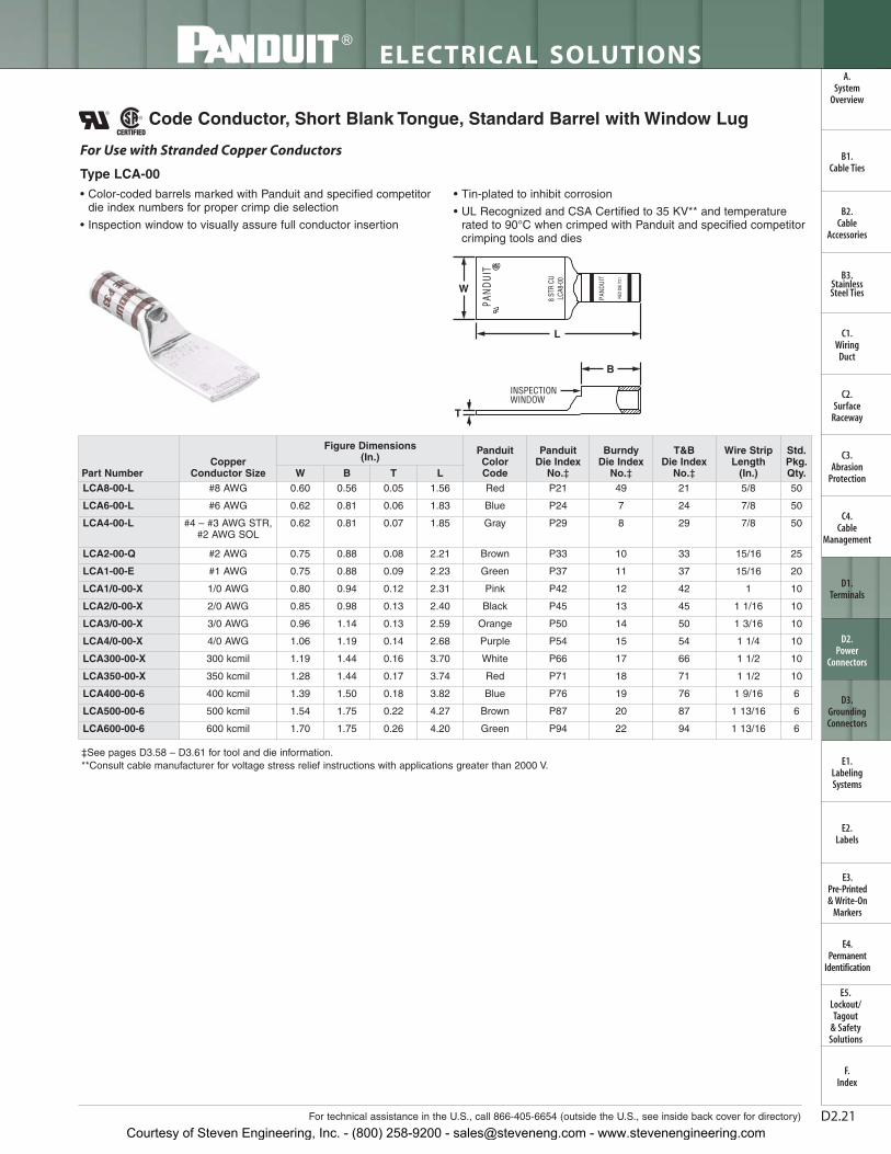
• Color-coded barrels marked with Panduit and specified competitordie index numbers for proper crimp die selection
• Inspection window to visually assure full conductor insertion
• Tin-plated to inhibit corrosion
• UL Recognized and CSA Certified to 35 KV** and temperaturerated to 90°C when crimped with Panduit and specified competitorcrimping tools and dies
W
INSPECTIONWINDOW
L
B
T
For Use with Stranded Copper Conductors
Type LCA-00
Code Conductor, Short Blank Tongue, Standard Barrel with Window Lug
Part NumberCopper
Conductor Size
Figure Dimensions (In.)
PanduitColorCode
PanduitDie Index
No.‡
Burndy Die Index
No.‡
T&B Die Index
No.‡
Wire StripLength
(In.)
Std.Pkg.Qty.W B T L
LCA8-00-L #8 AWG 0.60 0.56 0.05 1.56 Red P21 49 21 5/8 50
LCA6-00-L #6 AWG 0.62 0.81 0.06 1.83 Blue P24 7 24 7/8 50
LCA4-00-L #4 – #3 AWG STR,#2 AWG SOL
0.62 0.81 0.07 1.85 Gray P29 8 29 7/8 50
LCA2-00-Q #2 AWG 0.75 0.88 0.08 2.21 Brown P33 10 33 15/16 25
LCA1-00-E #1 AWG 0.75 0.88 0.09 2.23 Green P37 11 37 15/16 20
LCA1/0-00-X 1/0 AWG 0.80 0.94 0.12 2.31 Pink P42 12 42 1 10
LCA2/0-00-X 2/0 AWG 0.85 0.98 0.13 2.40 Black P45 13 45 1 1/16 10
LCA3/0-00-X 3/0 AWG 0.96 1.14 0.13 2.59 Orange P50 14 50 1 3/16 10
LCA4/0-00-X 4/0 AWG 1.06 1.19 0.14 2.68 Purple P54 15 54 1 1/4 10
LCA300-00-X 300 kcmil 1.19 1.44 0.16 3.70 White P66 17 66 1 1/2 10
LCA350-00-X 350 kcmil 1.28 1.44 0.17 3.74 Red P71 18 71 1 1/2 10
LCA400-00-6 400 kcmil 1.39 1.50 0.18 3.82 Blue P76 19 76 1 9/16 6
LCA500-00-6 500 kcmil 1.54 1.75 0.22 4.27 Brown P87 20 87 1 13/16 6
LCA600-00-6 600 kcmil 1.70 1.75 0.26 4.20 Green P94 22 94 1 13/16 6
Courtesy of Steven Engineering, Inc. - (800) 258-9200 - [email protected] - www.stevenengineering.com

D2.22
ELECTRICAL SOLUTIONS
Order number of pieces required, in multiples of Standard Package Quantity.
B2.Cable
Accessories
C1.Wiring
Duct
C3.Abrasion
Protection
C4.Cable
Management
D1.Terminals
D2.Power
Connectors
E1.LabelingSystems
E2.Labels
E3.Pre-Printed & Write-On
Markers
F.Index
B3.StainlessSteel Ties
C2.Surface
Raceway
E5.Lockout/Tagout
& SafetySolutions
B1.Cable Ties
A.System
Overview
D3.GroundingConnectors
E4.Permanent
Identification
Prime items appear in BOLD.
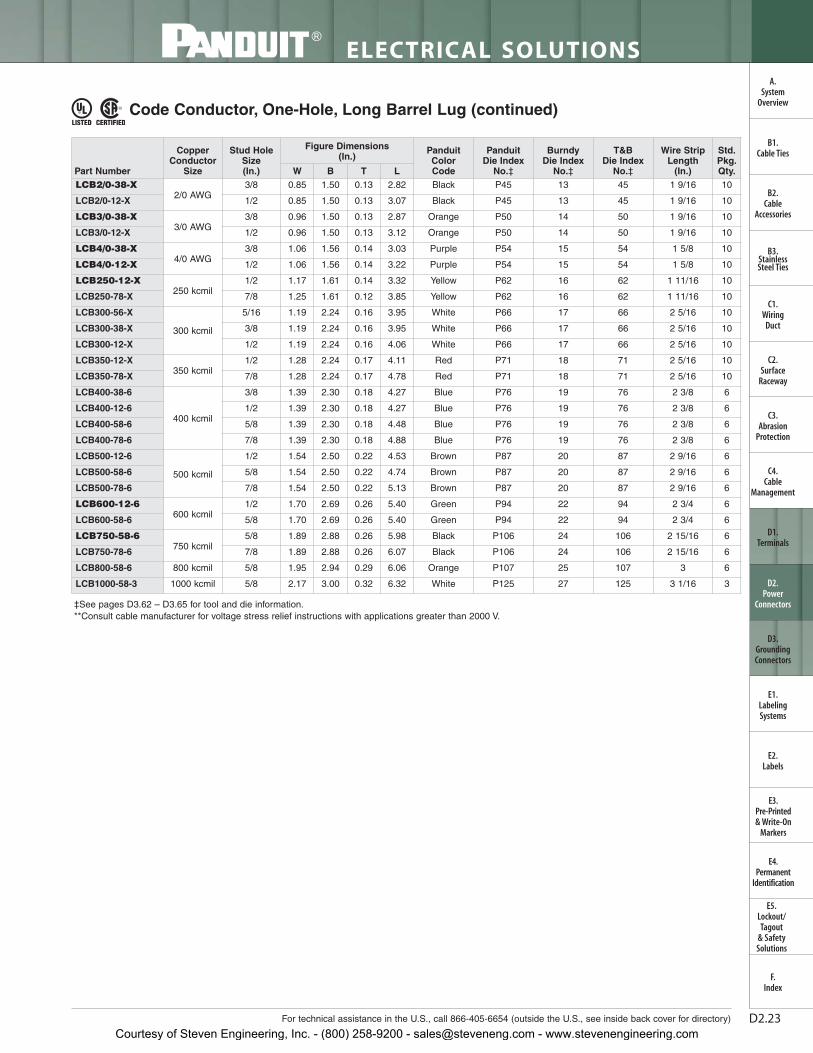
Code Conductor, One-Hole, Long Barrel Lug
• Long barrel maximizes number of crimps and provides premiumwire pull-out strength and electrical performance
• Color-coded barrels marked with Panduit and specified competitordie index numbers for proper crimp die selection
• Enclosed barrel prevents corrosive material from entering barrelwhen used in harsh environments
• Tin-plated to inhibit corrosion
• UL Listed and CSA Certified to 35 KV** and temperature rated to90°C when crimped with Panduit and specified competitorcrimping tools and dies
• UL Listed and CSA Certified for wide wire range-taking capabilitywhen crimped with Panduit ® Uni-Die ™ Dieless Crimping Tools‡
• Tested by Telcordia – meets NEBS Level 3
• American Bureau of Shipping Approved
L
B
W
T
For Use with Stranded Copper Conductors
Type LCB
‡See pages D3.62 – D3.65 for tool and die information.**Consult cable manufacturer for voltage stress relief instructions with applications greater than 2000 V.
Part Number
CopperConductor
Size
Stud HoleSize(In.)
Figure Dimensions (In.)
PanduitColor Code
Panduit Die Index
No.‡
Burndy Die Index
No.‡
T&B Die Index
No.‡
Wire StripLength
(In.)
Std.Pkg.Qty.W B T L
LCB8-10-L
#8 AWG
#10 0.41 0.70 0.08 1.44 Red P21 49 21 3/4 50
LCB8-14-L 1/4 0.48 0.70 0.07 1.53 Red P21 49 21 3/4 50
LCB8-38-L 3/8 0.60 0.70 0.05 1.75 Red P21 49 21 3/4 50
LCB6-10-L
#6 AWG
#10 0.45 1.07 0.09 1.84 Blue P24 7 24 1 1/8 50
LCB6-14-L 1/4 0.48 1.07 0.08 1.93 Blue P24 7 24 1 1/8 50
LCB6-38-L 3/8 0.62 1.07 0.05 2.15 Blue P24 7 24 1 1/8 50
LCB4-10-L#4 – #3
AWG STR,#2 AWG
SOL
#10 0.55 1.05 0.09 1.86 Gray P29 8 29 1 1/8 50
LCB4-14-L 1/4 0.55 1.05 0.09 1.95 Gray P29 8 29 1 1/8 50
LCB4-56-L 5/16 0.62 1.05 0.07 2.13 Gray P29 8 29 1 1/8 50
LCB4-38-L 3/8 0.62 1.05 0.07 2.17 Gray P29 8 29 1 1/8 50
LCB2-10-Q
#2 AWG
#10 0.60 1.16 0.10 2.07 Brown P33 10 33 1 1/4 25
LCB2-14-Q 1/4 0.60 1.16 0.10 2.14 Brown P33 10 33 1 1/4 25
LCB2-56-Q 5/16 0.66 1.16 0.10 2.27 Brown P33 10 33 1 1/4 25
LCB2-38-Q 3/8 0.66 1.16 0.10 2.34 Brown P33 10 33 1 1/4 25
LCB2-12-Q 1/2 0.75 1.16 0.08 2.58 Brown P33 10 33 1 1/4 25
LCB1-10-E
#1 AWG
#10 0.70 1.36 0.11 2.30 Green P37 11 37 1 7/16 20
LCB1-56-E 5/16 0.70 1.36 0.11 2.50 Green P37 11 37 1 7/16 20
LCB1-38-E 3/8 0.70 1.36 0.11 2.57 Green P37 11 37 1 7/16 20
LCB1-12-E 1/2 0.75 1.36 0.09 2.81 Green P37 11 37 1 7/16 20
LCB1/0-10-X
1/0 AWG
#10 0.76 1.44 0.12 2.41 Pink P42 12 42 1 1/2 10
LCB1/0-56-X 5/16 0.76 1.44 0.12 2.61 Pink P42 12 42 1 1/2 10
LCB1/0-38-X 3/8 0.76 1.44 0.12 2.69 Pink P42 12 42 1 1/2 10
LCB1/0-12-X 1/2 0.80 1.44 0.12 2.92 Pink P42 12 42 1 1/2 10
Courtesy of Steven Engineering, Inc. - (800) 258-9200 - [email protected] - www.stevenengineering.com
LTBW
Std.Pkg.Qty.
Wire StripLength
(In.)
T&B Die Index
No.‡
Burndy Die Index
No.‡
Panduit Die Index
No.‡
PanduitColor Code
Figure Dimensions (In.)
Stud HoleSize(In.)
CopperConductor
SizePart Number
D2.23For technical assistance in the U.S., call 866-405-6654 (outside the U.S., see inside back cover for directory)
ELECTRICAL SOLUTIONS
B2.Cable
Accessories
C1.Wiring
Duct
C3.Abrasion
Protection
C4.Cable
Management
D1.Terminals
D2.Power
Connectors
E1.LabelingSystems
E2.Labels
E3.Pre-Printed & Write-On
Markers
F.Index
B3.StainlessSteel Ties
C2.Surface
Raceway
E5.Lockout/Tagout
& SafetySolutions
B1.Cable Ties
A.System
Overview
D3.GroundingConnectors
E4.Permanent
Identification
‡See pages D3.62 – D3.65 for tool and die information.**Consult cable manufacturer for voltage stress relief instructions with applications greater than 2000 V.
Code Conductor, One-Hole, Long Barrel Lug (continued)
LCB2/0-38-X2/0 AWG
3/8 0.85 1.50 0.13 2.82 Black P45 13 45 1 9/16 10
LCB2/0-12-X 1/2 0.85 1.50 0.13 3.07 Black P45 13 45 1 9/16 10
LCB3/0-38-X3/0 AWG
3/8 0.96 1.50 0.13 2.87 Orange P50 14 50 1 9/16 10
LCB3/0-12-X 1/2 0.96 1.50 0.13 3.12 Orange P50 14 50 1 9/16 10
LCB4/0-38-X4/0 AWG
3/8 1.06 1.56 0.14 3.03 Purple P54 15 54 1 5/8 10
LCB4/0-12-X 1/2 1.06 1.56 0.14 3.22 Purple P54 15 54 1 5/8 10
LCB250-12-X250 kcmil
1/2 1.17 1.61 0.14 3.32 Yellow P62 16 62 1 11/16 10
LCB250-78-X 7/8 1.25 1.61 0.12 3.85 Yellow P62 16 62 1 11/16 10
LCB300-56-X
300 kcmil
5/16 1.19 2.24 0.16 3.95 White P66 17 66 2 5/16 10
LCB300-38-X 3/8 1.19 2.24 0.16 3.95 White P66 17 66 2 5/16 10
LCB300-12-X 1/2 1.19 2.24 0.16 4.06 White P66 17 66 2 5/16 10
LCB350-12-X350 kcmil
1/2 1.28 2.24 0.17 4.11 Red P71 18 71 2 5/16 10
LCB350-78-X 7/8 1.28 2.24 0.17 4.78 Red P71 18 71 2 5/16 10
LCB400-38-6
400 kcmil
3/8 1.39 2.30 0.18 4.27 Blue P76 19 76 2 3/8 6
LCB400-12-6 1/2 1.39 2.30 0.18 4.27 Blue P76 19 76 2 3/8 6
LCB400-58-6 5/8 1.39 2.30 0.18 4.48 Blue P76 19 76 2 3/8 6
LCB400-78-6 7/8 1.39 2.30 0.18 4.88 Blue P76 19 76 2 3/8 6
LCB500-12-6
500 kcmil
1/2 1.54 2.50 0.22 4.53 Brown P87 20 87 2 9/16 6
LCB500-58-6 5/8 1.54 2.50 0.22 4.74 Brown P87 20 87 2 9/16 6
LCB500-78-6 7/8 1.54 2.50 0.22 5.13 Brown P87 20 87 2 9/16 6
LCB600-12-6600 kcmil
1/2 1.70 2.69 0.26 5.40 Green P94 22 94 2 3/4 6
LCB600-58-6 5/8 1.70 2.69 0.26 5.40 Green P94 22 94 2 3/4 6
LCB750-58-6750 kcmil
5/8 1.89 2.88 0.26 5.98 Black P106 24 106 2 15/16 6
LCB750-78-6 7/8 1.89 2.88 0.26 6.07 Black P106 24 106 2 15/16 6
LCB800-58-6 800 kcmil 5/8 1.95 2.94 0.29 6.06 Orange P107 25 107 3 6
LCB1000-58-3 1000 kcmil 5/8 2.17 3.00 0.32 6.32 White P125 27 125 3 1/16 3
Courtesy of Steven Engineering, Inc. - (800) 258-9200 - [email protected] - www.stevenengineering.com

D2.24
ELECTRICAL SOLUTIONS
Prime items appear in BOLD.
B2.Cable
Accessories
C1.Wiring
Duct
C3.Abrasion
Protection
C4.Cable
Management
D1.Terminals
D2.Power
Connectors
E1.LabelingSystems
E2.Labels
E3.Pre-Printed & Write-On
Markers
F.Index
B3.StainlessSteel Ties
C2.Surface
Raceway
E5.Lockout/Tagout
& SafetySolutions
B1.Cable Ties
A.System
Overview
D3.GroundingConnectors
E4.Permanent
Identification
Code Conductor, One-Hole, Long Barrel Lug, 45° Angle
‡See pages D3.62 – D3.65 for tool and die information.**Consult cable manufacturer for voltage stress relief instructions with applications greater than 2000 V.
• Long barrel maximizes number of crimps and provides premiumwire pull-out strength and electrical performance
• Color-coded barrels marked with Panduit and specified competitordie index numbers for proper crimp die selection
• Enclosed barrel prevents corrosive material from entering barrel when used in harsh environments
• Tin-plated to inhibit corrosion
• UL Listed and CSA Certified to 35 KV** and temperature rated to 90°C when crimped with Panduit and specified competitorcrimping tools and dies
• UL Listed and CSA Certified for wide wire range-taking capabilitywhen crimped with Panduit® Uni-Die™ Dieless Crimping Tools‡
• Tested by Telcordia – meets NEBS Level 3
• American Bureau of Shipping approved
45˚
L
W
T
B
For Use with Stranded Copper Conductors
Type LCB-H
Part Number
CopperConductor
Size
Stud HoleSize(In.)
Figure Dimensions (In.) Panduit
Color Code
Panduit Die Index
No.‡
Burndy Die Index
No.‡
T&B Die Index
No.‡
Wire StripLength
(In.)
Std.Pkg.Qty.W B T L
LCB8-10H-L#8 AWG
#10 0.41 0.70 0.08 1.23 Red P21 49 21 3/4 50
LCB8-14H-L 1/4 0.48 0.70 0.07 1.31 Red P21 49 21 3/4 50
LCB6-10H-L
#6 AWG
#10 0.45 1.07 0.09 1.52 Blue P24 7 24 1 1/8 50
LCB6-14H-L 1/4 0.48 1.07 0.08 1.60 Blue P24 7 24 1 1/8 50
LCB6-38H-L 3/8 0.62 1.07 0.05 1.81 Blue P24 7 24 1 1/8 50
LCB4-10H-L #4 – #3AWG STR,
#2 AWGSOL
#10 0.55 1.05 0.09 1.54 Gray P29 8 29 1 1/8 50
LCB4-14H-L 1/4 0.55 1.05 0.09 1.63 Gray P29 8 29 1 1/8 50
LCB2-10H-Q#2 AWG
#10 0.60 1.16 0.10 1.68 Brown P33 10 33 1 1/4 25
LCB2-56H-Q 5/16 0.66 1.16 0.10 1.87 Brown P33 10 33 1 1/4 25
LCB1-10H-E#1 AWG
#10 0.70 1.36 0.11 1.83 Green P37 11 37 1 7/16 20
LCB1-56H-E 5/16 0.70 1.36 0.11 2.03 Green P37 11 37 1 7/16 20
LCB1/0-10H-X
1/0 AWG
#10 0.76 1.44 0.12 1.92 Pink P42 12 42 1 1/2 10
LCB1/0-56H-X 5/16 0.76 1.44 0.12 2.12 Pink P42 12 42 1 1/2 10
LCB1/0-38H-X 3/8 0.76 1.44 0.12 2.19 Pink P42 12 42 1 1/2 10
LCB1/0-12H-X 1/2 0.80 1.44 0.11 2.42 Pink P42 12 42 1 1/2 10
LCB2/0-38H-X2/0 AWG
3/8 0.85 1.50 0.13 2.31 Black P45 13 45 1 9/16 10
LCB2/0-12H-X 1/2 0.85 1.50 0.13 2.53 Black P45 13 45 1 9/16 10
LCB3/0-38H-X3/0 AWG
3/8 0.96 1.50 0.13 2.33 Orange P50 14 50 1 9/16 10
LCB3/0-12H-X 1/2 0.96 1.50 0.13 2.58 Orange P50 14 50 1 9/16 10
Courtesy of Steven Engineering, Inc. - (800) 258-9200 - [email protected] - www.stevenengineering.com

LTBW
Std.Pkg.Qty.
Wire StripLength
(In.)
T&B Die Index
No.‡
Burndy Die Index
No.‡
Panduit Die Index
No.‡Panduit
Color Code
Figure Dimensions (In.)
Stud HoleSize(In.)
CopperConductor
SizePart Number
D2.25For technical assistance in the U.S., call 866-405-6654 (outside the U.S., see inside back cover for directory)
ELECTRICAL SOLUTIONS
B2.Cable
Accessories
C1.Wiring
Duct
C3.Abrasion
Protection
C4.Cable
Management
D1.Terminals
D2.Power
Connectors
E1.LabelingSystems
E2.Labels
E3.Pre-Printed & Write-On
Markers
F.Index
B3.StainlessSteel Ties
C2.Surface
Raceway
E5.Lockout/Tagout
& SafetySolutions
B1.Cable Ties
A.System
Overview
D3.GroundingConnectors
E4.Permanent
Identification
‡See pages D3.62 – D3.65 for tool and die information.**Consult cable manufacturer for voltage stress relief instructions with applications greater than 2000 V.
Code Conductor, One-Hole, Long Barrel Lug, 45° Angle (continued)
LCB4/0-38H-X4/0 AWG
3/8 1.06 1.56 0.14 2.48 Purple P54 15 54 1 5/8 10
LCB4/0-12H-X 1/2 1.06 1.56 0.14 2.67 Purple P54 15 54 1 5/8 10
LCB250-12H-X250 kcmil
1/2 1.17 1.61 0.14 2.74 Yellow P62 16 62 1 11/16 10
LCB250-78H-X 7/8 1.25 1.61 0.12 3.27 Yellow P62 16 62 1 11/16 10
LCB300-56H-X
300 kcmil
5/16 1.19 2.24 0.16 3.24 White P66 17 66 2 5/16 10
LCB300-38H-X 3/8 1.19 2.24 0.16 3.24 White P66 17 66 2 5/16 10
LCB300-12H-X 1/2 1.19 2.24 0.16 3.35 White P66 17 66 2 5/16 10
LCB350-12H-X350 kcmil
1/2 1.28 2.24 0.17 3.39 Red P71 18 71 2 5/16 10
LCB350-78H-X 7/8 1.28 2.24 0.17 4.04 Red P71 18 71 2 5/16 10
LCB400-12H-6
400 kcmil
1/2 1.39 2.30 0.18 3.53 Blue P76 19 76 2 3/8 6
LCB400-58H-6 5/8 1.39 2.30 0.18 3.74 Blue P76 19 76 2 3/8 6
LCB400-78H-6 7/8 1.39 2.30 0.18 4.13 Blue P76 19 76 2 3/8 6
LCB500-12H-6
500 kcmil
1/2 1.54 2.50 0.22 3.74 Brown P87 20 87 2 9/16 6
LCB500-58H-6 5/8 1.54 2.50 0.22 3.95 Brown P87 20 87 2 9/16 6
LCB500-78H-6 7/8 1.54 2.50 0.22 4.34 Brown P87 20 87 2 9/16 6
LCB600-12H-6600 kcmil
1/2 1.70 2.69 0.26 4.56 Green P94 22 94 2 3/4 6
LCB600-58H-6 5/8 1.70 2.69 0.26 4.56 Green P94 22 94 2 3/4 6
Courtesy of Steven Engineering, Inc. - (800) 258-9200 - [email protected] - www.stevenengineering.com

D2.26
ELECTRICAL SOLUTIONS
Prime items appear in BOLD.
B2.Cable
Accessories
C1.Wiring
Duct
C3.Abrasion
Protection
C4.Cable
Management
D1.Terminals
D2.Power
Connectors
E1.LabelingSystems
E2.Labels
E3.Pre-Printed & Write-On
Markers
F.Index
B3.StainlessSteel Ties
C2.Surface
Raceway
E5.Lockout/Tagout
& SafetySolutions
B1.Cable Ties
A.System
Overview
D3.GroundingConnectors
E4.Permanent
Identification
Code Conductor, One-Hole, Long Barrel Lug, 90° Angle
• Long barrel maximizes number of crimps and provides premiumwire pull-out strength and electrical performance
• Color-coded barrels marked with Panduit and specified competitordie index numbers for proper crimp die selection
• Enclosed barrel prevents corrosive material from entering barrel when used in harsh environments
• Tin-plated to inhibit corrosion
• UL Listed and CSA Certified to 35 KV** and temperature rated to 90°C when crimped with Panduit and specified competitorcrimping tools and dies
• UL Listed and CSA Certified for wide wire range-taking capabilitywhen crimped with Panduit® Uni-Die™ Dieless Crimping Tools‡
• Tested by Telcordia – meets NEBS Level 3
• American Bureau of Shipping approved
W
T
B
L
90˚
For Use with Stranded Copper Conductors
Type LCB-F
‡See pages D3.62 – D3.65 for tool and die information.**Consult cable manufacturer for voltage stress relief instructions with applications greater than 2000 V.
Part Number
CopperConductor
Size
Stud HoleSize(In.)
Figure Dimensions (In.)
PanduitColorCode
Panduit Die Index
No.‡
Burndy Die Index
No.‡
T&B Die Index
No.‡
Wire StripLength
(In.)
Std.Pkg.Qty.W B T L
LCB8-10F-L#8 AWG
#10 0.41 0.70 0.08 1.08 Red P21 49 21 3/4 50
LCB8-14F-L 1/4 0.48 0.70 0.07 1.07 Red P21 49 21 3/4 50
LCB6-10F-L
#6 AWG
#10 0.45 1.07 0.09 1.49 Blue P24 7 24 1 1/8 50
LCB6-14F-L 1/4 0.48 1.07 0.08 1.48 Blue P24 7 24 1 1/8 50
LCB6-38F-L 3/8 0.62 1.07 0.05 1.45 Blue P24 7 24 1 1/8 50
LCB4-10F-L #4 – #3AWG STR,
#2 AWGSOL
#10 0.55 1.05 0.09 1.53 Gray P29 8 29 1 1/8 50
LCB4-14F-L 1/4 0.55 1.05 0.09 1.53 Gray P29 8 29 1 1/8 50
LCB2-10F-Q#2 AWG
#10 0.60 1.16 0.10 1.75 Brown P33 10 33 1 1/4 25
LCB2-56F-Q 5/16 0.66 1.16 0.10 1.74 Brown P33 10 33 1 1/4 25
LCB1-10F-E#1 AWG
#10 0.70 1.36 0.11 2.00 Green P37 11 37 1 7/16 20
LCB1-56F-E 5/16 0.70 1.36 0.11 2.00 Green P37 11 37 1 7/16 20
LCB1/0-10F-X
1/0 AWG
#10 0.76 1.44 0.12 2.15 Pink P42 12 42 1 1/2 10
LCB1/0-56F-X 5/16 0.76 1.44 0.12 2.15 Pink P42 12 42 1 1/2 10
LCB1/0-38F-X 3/8 0.76 1.44 0.12 2.15 Pink P42 12 42 1 1/2 10
LCB1/0-12F-X 1/2 0.80 1.44 0.12 2.14 Pink P42 12 42 1 1/2 10
LCB2/0-38F-X 2/0 AWG 3/8 0.85 1.50 0.13 2.30 Black P45 13 45 1 9/16 10
LCB3/0-38F-X3/0 AWG
3/8 0.96 1.50 0.13 2.35 Orange P50 14 50 1 9/16 10
LCB3/0-12F-X 1/2 0.96 1.50 0.13 2.35 Orange P50 14 50 1 9/16 10
LCB4/0-38F-X4/0 AWG
3/8 1.06 1.56 0.14 2.48 Purple P54 15 54 1 5/8 10
LCB4/0-12F-X 1/2 1.06 1.56 0.14 2.48 Purple P54 15 54 1 5/8 10
Courtesy of Steven Engineering, Inc. - (800) 258-9200 - [email protected] - www.stevenengineering.com

LTBW
Std.Pkg.Qty.
Wire StripLength
(In.)
T&B Die Index
No.‡
Burndy DieIndexNo.‡
Panduit Die Index
No.‡
PanduitColorCode
Figure Dimensions (In.)
Stud HoleSize(In.)
CopperConductor
SizePart Number
D2.27For technical assistance in the U.S., call 866-405-6654 (outside the U.S., see inside back cover for directory)
ELECTRICAL SOLUTIONS
B2.Cable
Accessories
C1.Wiring
Duct
C3.Abrasion
Protection
C4.Cable
Management
D1.Terminals
D2.Power
Connectors
E1.LabelingSystems
E2.Labels
E3.Pre-Printed & Write-On
Markers
F.Index
B3.StainlessSteel Ties
C2.Surface
Raceway
E5.Lockout/Tagout
& SafetySolutions
B1.Cable Ties
A.System
Overview
D3.GroundingConnectors
E4.Permanent
Identification
‡See pages D3.62 – D3.65 for tool and die information.**Consult cable manufacturer for voltage stress relief instructions with applications greater than 2000 V.
Code Conductor, One-Hole, Long Barrel Lug, 90° Angle (continued)
LCB250-12F-X250 kcmil
1/2 1.17 1.61 0.14 2.57 Yellow P62 16 62 1 11/16 10
LCB250-78F-X 7/8 1.25 1.61 0.12 2.49 Yellow P62 16 62 1 11/16 10
LCB350-12F-X350 kcmil
1/2 1.28 2.24 0.17 3.34 Red P71 18 71 2 5/16 10
LCB350-78F-X 7/8 1.28 2.24 0.17 3.34 Red P71 18 71 2 5/16 10
LCB400-58F-6400 kcmil
5/8 1.39 2.30 0.18 3.47 Blue P76 19 76 2 3/8 6
LCB400-78F-6 7/8 1.39 2.30 0.18 3.47 Blue P76 19 76 2 3/8 6
LCB500-12F-6
500 kcmil
1/2 1.54 2.50 0.22 3.77 Brown P87 20 87 2 9/16 6
LCB500-58F-6 5/8 1.54 2.50 0.22 3.77 Brown P87 20 87 2 9/16 6
LCB500-78F-6 7/8 1.54 2.50 0.22 3.77 Brown P87 20 87 2 9/16 6
LCB600-12F-6600 kcmil
1/2 1.70 2.69 0.26 4.08 Green P94 22 94 2 3/4 6
LCB600-58F-6 5/8 1.70 2.69 0.26 4.08 Green P94 22 94 2 3/4 6
Courtesy of Steven Engineering, Inc. - (800) 258-9200 - [email protected] - www.stevenengineering.com

D2.28
ELECTRICAL SOLUTIONS
Prime items appear in BOLD.
B2.Cable
Accessories
C1.Wiring
Duct
C3.Abrasion
Protection
C4.Cable
Management
D1.Terminals
D2.Power
Connectors
E1.LabelingSystems
E2.Labels
E3.Pre-Printed & Write-On
Markers
F.Index
B3.StainlessSteel Ties
C2.Surface
Raceway
E5.Lockout/Tagout
& SafetySolutions
B1.Cable Ties
A.System
Overview
D3.GroundingConnectors
E4.Permanent
Identification
Code Conductor, One-Hole, Long Barrel with Window Lug
‡See pages D3.62 – D3.65 for tool and die information.*Not tested to NEBS Level 3 requirements.**Consult cable manufacturer for voltage stress relief instructions with applications greater than 2000 V.
T
INSPECTIONWINDOW
W
L
B
For Use with Stranded Copper Conductors
Type LCB-W• Long barrel maximizes number of crimps and provides premium
wire pull-out strength and electrical performance
• Inspection window to visually assure full conductor insertion
• Color-coded barrels marked with Panduit and specified competitordie index numbers for proper crimp die selection
• Tin-plated to inhibit corrosion
• UL Listed and CSA Certified to 35 KV** and temperature rated to 90°C when crimped with Panduit and specified competitorcrimping tools and dies
• UL Listed and CSA Certified for wide wire range-taking capabilitywhen crimped with Panduit ® Uni-Die ™ Dieless Crimping Tools‡
• Tested by Telcordia – meets NEBS Level 3
• Meets J-STD-607-A and TIA-942 requirements for networksystems grounding applications
Part Number
CopperConductor
Size
Stud HoleSize(In.)
Figure Dimensions (In.) Panduit
Color Code
Panduit Die Index
No.‡
Burndy Die Index
No.‡
T&B Die Index
No.‡
Wire StripLength
(In.)
Std.Pkg.Qty.W B T L
LCB10-14W-L* #14 – #10AWG STR,#12 – #10AWG SOL
1/4 0.42 0.53 0.05 1.31 — — — — 9/16 50
LCB750-38W-6
750 kcmil
3/8 1.89 2.88 0.26 4.83 Black P106 24 106 2 15/16 6
LCB750-12W-6 1/2 1.89 2.88 0.26 5.03 Black P106 24 106 2 15/16 6
LCB750-58W-6 5/8 1.89 2.88 0.26 5.58 Black P106 24 106 2 15/16 6
LCB750-78W-6 7/8 1.89 2.88 0.26 5.68 Black P106 24 106 2 15/16 6
LCB800-12W-6800 kcmil
1/2 1.95 2.94 0.30 5.11 Orange P107 25 107 3 6
LCB800-58W-6 5/8 1.95 2.94 0.30 5.68 Orange P107 25 107 3 6
LCB1000-38W-3
1000 kcmil
3/8 2.17 3.00 0.32 5.08 White P125 27 125 3 1/16 3
LCB1000-12W-3 1/2 2.17 3.00 0.32 5.27 White P125 27 125 3 1/16 3
LCB1000-58W-3 5/8 2.17 3.00 0.32 5.92 White P125 27 125 3 1/16 3
Courtesy of Steven Engineering, Inc. - (800) 258-9200 - [email protected] - www.stevenengineering.com

D2.29For technical assistance in the U.S., call 866-405-6654 (outside the U.S., see inside back cover for directory)
ELECTRICAL SOLUTIONS
B2.Cable
Accessories
C1.Wiring
Duct
C3.Abrasion
Protection
C4.Cable
Management
D1.Terminals
D2.Power
Connectors
E1.LabelingSystems
E2.Labels
E3.Pre-Printed & Write-On
Markers
F.Index
B3.StainlessSteel Ties
C2.Surface
Raceway
E5.Lockout/Tagout
& SafetySolutions
B1.Cable Ties
A.System
Overview
D3.GroundingConnectors
E4.Permanent
Identification
Code Conductor, One-Hole, Long Barrel with Window Lug, 45° Angle
‡See pages D3.62 – D3.65 for tool and die information.**Consult cable manufacturer for voltage stress relief instructions with applications greater than 2000 V.
Code Conductor, One-Hole, Long Barrel with Window Lug, 90° Angle
‡See pages D3.62 – D3.65 for tool and die information.**Consult cable manufacturer for voltage stress relief instructions with applications greater than 2000 V.
• Long barrel maximizes number of crimps and provides premiumwire pull-out strength and electrical performance
• Inspection window to visually assure full conductor insertion
• Tin-plated to inhibit corrosion
• UL Listed and CSA Certified to 35 KV** and temperature rated to 90°C when crimped with Panduit crimping tools and dies
• Meets J-STD-607-A and TIA-942 requirements for networksystems grounding applications
W
T
INSPECTIONWINDOW 45˚
L
B
For Use with Stranded Copper Conductors
Type LCB-WH
• Long barrel maximizes number of crimps and provides premiumwire pull-out strength and electrical performance
• Inspection window to visually assure full conductor insertion
• Tin-plated to inhibit corrosion
• UL Listed and CSA Certified to 35 KV** and temperature rated to 90°C when crimped with Panduit crimping tools and dies
• Meets J-STD-607-A and TIA-942 requirements for networksystems grounding applications
W INSPECTIONWINDOW
T
L
B
90˚
For Use with Stranded Copper Conductors
Type LCB-WF
Part Number
CopperConductor
Size
Stud HoleSize(In.)
Figure Dimensions (In.)
PanduitColorCode
PanduitDie Index
No.‡
BurndyDie Index
No.‡
T&BDie Index
No.‡
Wire StripLength
(In.)
Std.Pkg.Qty.W B T L
LCB10-14WH-L #14 – #10AWG STR,#12 – #10AWG SOL
1/4 0.42 0.53 0.05 1.15 — — — — 9/16 50
Part Number
CopperConductor
Size
Stud HoleSize(In.)
Figure Dimensions (In.) Panduit
Color Code
Paduit Die Index
No.‡
BurndyDie Index
No.‡
T&BDie Index
No.‡
Wire StripLength
(In.)
Std.Pkg.Qty.W B T L
LCB10-14WF-L #14 – #10AWG STR,#12 – #10AWG SOL
1/4 0.42 0.53 0.05 0.94 — — — — 9/16 50
Courtesy of Steven Engineering, Inc. - (800) 258-9200 - [email protected] - www.stevenengineering.com

D2.30
ELECTRICAL SOLUTIONS
Prime items appear in BOLD.
B2.Cable
Accessories
C1.Wiring
Duct
C3.Abrasion
Protection
C4.Cable
Management
D1.Terminals
D2.Power
Connectors
E1.LabelingSystems
E2.Labels
E3.Pre-Printed & Write-On
Markers
F.Index
B3.StainlessSteel Ties
C2.Surface
Raceway
E5.Lockout/Tagout
& SafetySolutions
B1.Cable Ties
A.System
Overview
D3.GroundingConnectors
E4.Permanent
Identification
Code Conductor, One-Hole, Long Barrel with Corona Relief Taper Lug
‡See pages D3.66, D3.67 for tool and die information.**Consult cable manufacturer for voltage stress relief instructions with applications greater than 2000 V.
CORONARELIEFTAPER
L
W
B
T
• Externally chamfered barrel end inhibits Corona effect when used in high voltage applications
• Long barrel maximizes number of crimps and provides premiumwire pull-out strength and electrical performance
• Color-coded barrels marked with Panduit and specified competitordie index numbers for proper crimp die selection
• Enclosed barrel prevents corrosive material from entering barrelwhen used in harsh environments
• Tin-plated to inhibit corrosion
• UL Listed and CSA Certified to 35 KV** and temperature rated to 90°C when crimped with Panduit and specified competitorcrimping tools and dies
To Facilitate Use with Stranded Copper Conductors in Applications of 5000 V or More
Type LCBH
Corona Relief Taper
Part Number
CopperConductor
Size
Stud HoleSize (In.)
Figure Dimensions (In.) Panduit
Color Code
Panduit Die Index
No.‡
Burndy Die Index
No.‡
T&B Die Index
No.‡
Wire StripLength
(In.)
Std.Pkg.Qty.W B T L
LCBH4-38-L #4 AWG 3/8 0.62 1.05 0.07 2.16 Gray P29 8 29 1 1/8 50
LCBH2-38-Q #2 AWG 3/8 0.66 1.16 0.10 2.34 Brown P33 10 33 1 1/4 25
LCBH1-38-E #1 AWG 3/8 0.70 1.36 0.10 2.57 Green P37 11 37 1 7/16 20
LCBH1/0-38-X 1/0 AWG 3/8 0.76 1.44 0.12 2.69 Pink P42 12 42 1 1/2 10
LCBH2/0-12-X 2/0 AWG 1/2 0.85 1.50 0.13 3.07 Black P45 13 45 1 9/16 10
LCBH3/0-12-X 3/0 AWG 1/2 0.96 1.50 0.13 3.12 Orange P50 14 50 1 9/16 10
LCBH4/0-12-X 4/0 AWG 1/2 1.06 1.56 0.14 3.22 Purple P54 15 54 1 5/8 10
LCBH250-12-X 250 kcmil 1/2 1.17 1.61 0.14 3.32 Yellow P62 16 62 1 11/16 10
Courtesy of Steven Engineering, Inc. - (800) 258-9200 - [email protected] - www.stevenengineering.com

D2.31For technical assistance in the U.S., call 866-405-6654 (outside the U.S., see inside back cover for directory)
ELECTRICAL SOLUTIONS
B2.Cable
Accessories
C1.Wiring
Duct
C3.Abrasion
Protection
C4.Cable
Management
D1.Terminals
D2.Power
Connectors
E1.LabelingSystems
E2.Labels
E3.Pre-Printed & Write-On
Markers
F.Index
B3.StainlessSteel Ties
C2.Surface
Raceway
E5.Lockout/Tagout
& SafetySolutions
B1.Cable Ties
A.System
Overview
D3.GroundingConnectors
E4.Permanent
Identification
Code Conductor, Two-Hole, Standard Barrel with Window Lug
• Color-coded barrels marked with Panduit and specified competitordie index numbers for proper crimp die selection
• Inspection window to visually assure full conductor insertion
• Tin-plated to inhibit corrosion
• UL Listed and CSA Certified to 35 KV** and temperature rated to 90°C when crimped with Panduit and specified competitorcrimping tools and dies
• UL Listed and CSA Certified for wide wire range-taking capabilitywhen crimped with Panduit® Uni-Die ™ Dieless Crimping Tools‡
• Tested by Telcordia – meets NEBS Level 3
• American Bureau of Shipping approved
• Available with NEMA hole sizes and spacing
W
HOLESPACING
L
T
INSPECTIONWINDOW
B
For Use with Stranded Copper Conductors
Type LCD
‡See pages D3.58 – D3.61 for tool and die information.*Not tested to NEBS Level 3 requirements.**Consult cable manufacturer for voltage stress relief instructions with applications greater than 2000 V.
Table continues on page D2.32
Part Number
CopperConductor
Size
Stud HoleSize(In.)
Stud HoleSpacing
(In.)
Figure Dimensions (In.) Panduit
Color Code
PanduitDie Index
No.‡
BurndyDie Index
No.‡
T&BDie Index
No.‡
Wire StripLength
(In.)
Std.Pkg.Qty.W B T L
LCD10-10A-L*
#14 – #10AWG STR,#12 – #10AWG SOL
#10 0.63 0.38 0.38 0.06 1.69 — — — — 7/16 50
LCD10-14A-L* 1/4 0.63 0.42 0.38 0.05 1.78 — — — — 7/16 50
LCD10-14B-L* 1/4 0.75 0.42 0.38 0.05 1.91 — — — — 7/16 50
LCD10-14D-L* 1/4 1.00 0.42 0.38 0.05 2.16 — — — — 7/16 50
LCD10-38D-L* 3/8 1.00 0.56 0.38 0.04 2.38 — — — — 7/16 50
LCD8-10A-L
#8 AWG
#10 0.63 0.41 0.56 0.08 1.88 Red P21 49 21 5/8 50
LCD8-14A-L 1/4 0.63 0.48 0.56 0.07 1.97 Red P21 49 21 5/8 50
LCD8-14B-L 1/4 0.75 0.48 0.56 0.07 2.09 Red P21 49 21 5/8 50
LCD8-14D-L 1/4 1.00 0.48 0.56 0.07 2.34 Red P21 49 21 5/8 50
LCD8-38D-L 3/8 1.00 0.60 0.56 0.05 2.56 Red P21 49 21 5/8 50
LCD6-10A-L
#6 AWG
#10 0.63 0.46 0.81 0.08 2.15 Blue P24 7 24 7/8 50
LCD6-10B-L #10 0.75 0.46 0.81 0.08 2.27 Blue P24 7 24 7/8 50
LCD6-10D-L #10 1.00 0.46 0.81 0.08 2.52 Blue P24 7 24 7/8 50
LCD6-14A-L 1/4 0.63 0.48 0.81 0.08 2.24 Blue P24 7 24 7/8 50
LCD6-14B-L 1/4 0.75 0.48 0.81 0.08 2.36 Blue P24 7 24 7/8 50
LCD6-14D-L 1/4 1.00 0.48 0.81 0.08 2.61 Blue P24 7 24 7/8 50
LCD6-56D-L 5/16 1.00 0.56 0.81 0.07 2.73 Blue P24 7 24 7/8 50
LCD6-38D-L 3/8 1.00 0.62 0.81 0.06 2.83 Blue P24 7 24 7/8 50
LCD4-10A-L
#4 – #3AWG STR,
#2 AWGSOL
#10 0.63 0.55 0.81 0.09 2.17 Gray P29 8 29 7/8 50
LCD4-10B-L #10 0.75 0.55 0.81 0.09 2.29 Gray P29 8 29 7/8 50
LCD4-14A-L 1/4 0.63 0.55 0.81 0.09 2.26 Gray P29 8 29 7/8 50
LCD4-14B-L 1/4 0.75 0.55 0.81 0.09 2.38 Gray P29 8 29 7/8 50
LCD4-14D-L 1/4 1.00 0.55 0.81 0.09 2.63 Gray P29 8 29 7/8 50
LCD4-38D-L 3/8 1.00 0.62 0.81 0.08 2.85 Gray P29 8 29 7/8 50
LCD2-14A-Q
#2 AWG
1/4 0.63 0.60 0.88 0.10 2.40 Brown P33 10 33 15/16 25
LCD2-14B-Q 1/4 0.75 0.60 0.88 0.10 2.52 Brown P33 10 33 15/16 25
LCD2-14D-Q 1/4 1.00 0.60 0.88 0.10 2.77 Brown P33 10 33 15/16 25
LCD2-56B-Q 5/16 0.75 0.66 0.88 0.10 2.65 Brown P33 10 33 15/16 25
LCD2-38D-Q 3/8 1.00 0.66 0.88 0.10 3.00 Brown P33 10 33 15/16 25
LCD2-12-Q 1/2 1.75 0.75 0.88 0.08 4.14 Brown P33 10 33 15/16 25
Courtesy of Steven Engineering, Inc. - (800) 258-9200 - [email protected] - www.stevenengineering.com

D2.32
ELECTRICAL SOLUTIONS
Prime items appear in BOLD.
B2.Cable
Accessories
C1.Wiring
Duct
C3.Abrasion
Protection
C4.Cable
Management
D1.Terminals
D2.Power
Connectors
E1.LabelingSystems
E2.Labels
E3.Pre-Printed & Write-On
Markers
F.Index
B3.StainlessSteel Ties
C2.Surface
Raceway
E5.Lockout/Tagout
& SafetySolutions
B1.Cable Ties
A.System
Overview
D3.GroundingConnectors
E4.Permanent
Identification‡See pages D3.58 – D3.61 for tool and die information.**Consult cable manufacturer for voltage stress relief instructions with applications greater than 2000 V.◆NEMA hole sizes and spacing.
Code Conductor, Two-Hole, Standard Barrel with Window Lug (continued)
LTBW
Std.Pkg.Qty.
Wire StripLength
(In.)
T&BDie Index
No.‡
BurndyDie Index
No.‡
PanduitDie Index
No.‡
PanduitColor Code
Figure Dimensions (In.)Stud Hole
Spacing(In.)
Stud HoleSize(In.)
CopperConductor
SizePart NumberLCD1-14A-E
#1 AWG
1/4 0.63 0.70 0.88 0.11 2.42 Green P37 11 37 15/16 20
LCD1-14B-E 1/4 0.75 0.70 0.88 0.11 2.54 Green P37 11 37 15/16 20
LCD1-56C-E 5/16 0.88 0.70 0.88 0.11 2.79 Green P37 11 37 15/16 20
LCD1-38D-E 3/8 1.00 0.70 0.88 0.11 2.99 Green P37 11 37 15/16 20
LCD1-12-E 1/2 1.75 0.75 0.88 0.09 4.16 Green P37 11 37 15/16 20
LCD1/0-14A-X
1/0 AWG
1/4 0.63 0.76 0.94 0.12 2.57 Pink P42 12 42 1 10
LCD1/0-14B-X 1/4 0.75 0.76 0.94 0.12 2.70 Pink P42 12 42 1 10
LCD1/0-56C-X 5/16 0.88 0.76 0.94 0.12 2.88 Pink P42 12 42 1 10
LCD1/0-38D-X 3/8 1.00 0.76 0.94 0.12 3.08 Pink P42 12 42 1 10
LCD1/0-12-X 1/2 1.75 0.80 0.94 0.12 4.25 Pink P42 12 42 1 10
LCD2/0-14A-X
2/0 AWG
1/4 0.63 0.85 0.98 0.13 2.70 Black P45 13 45 1 1/16 10
LCD2/0-14B-X 1/4 0.75 0.85 0.98 0.13 2.83 Black P45 13 45 1 1/16 10
LCD2/0-56C-X 5/16 0.88 0.85 0.98 0.13 2.95 Black P45 13 45 1 1/16 10
LCD2/0-38D-X 3/8 1.00 0.85 0.98 0.13 3.14 Black P45 13 45 1 1/16 10
LCD2/0-12-X 1/2 1.75 0.85 0.98 0.13 4.30 Black P45 13 45 1 1/16 10
LCD3/0-14B-X
3/0 AWG
1/4 0.75 0.96 1.14 0.13 3.02 Orange P50 14 50 1 3/16 10
LCD3/0-56D-X 5/16 1.00 0.96 1.14 0.13 3.27 Orange P50 14 50 1 3/16 10
LCD3/0-38D-X 3/8 1.00 0.96 1.14 0.13 3.33 Orange P50 14 50 1 3/16 10
LCD3/0-12-X 1/2 1.75 0.96 1.14 0.13 4.49 Orange P50 14 50 1 3/16 10
LCD4/0-14B-X
4/0 AWG
1/4 0.75 1.06 1.19 0.14 3.10 Purple P54 15 54 1 1/4 10
LCD4/0-38D-X 3/8 1.00 1.06 1.19 0.14 3.44 Purple P54 15 54 1 1/4 10
◆ LCD4/0-12-X 1/2 1.75 1.06 1.19 0.14 4.58 Purple P54 15 54 1 1/4 10
LCD250-38D-X250 kcmil
3/8 1.00 1.17 1.25 0.14 3.54 Yellow P62 16 62 1 5/16 10
◆ LCD250-12-X 1/2 1.75 1.17 1.25 0.14 4.68 Yellow P62 16 62 1 5/16 10
LCD300-38D-X300 kcmil
3/8 1.00 1.19 1.44 0.16 3.74 White P66 17 66 1 1/2 10
◆ LCD300-12-X 1/2 1.75 1.19 1.44 0.16 4.92 White P66 17 66 1 1/2 10
LCD350-14B-X
350 kcmil
1/4 0.75 1.28 1.44 0.17 3.30 Red P71 18 71 1 1/2 10
LCD350-38D-X 3/8 1.00 1.28 1.44 0.17 3.78 Red P71 18 71 1 1/2 10
LCD350-12E-X 1/2 1.25 1.28 1.44 0.17 4.33 Red P71 18 71 1 1/2 10
◆ LCD350-12-X 1/2 1.75 1.28 1.44 0.17 4.96 Red P71 18 71 1 1/2 10
LCD400-38D-6400 kcmil
3/8 1.00 1.39 1.50 0.18 3.86 Blue P76 19 76 1 9/16 6
◆ LCD400-12-6 1/2 1.75 1.39 1.50 0.18 5.04 Blue P76 19 76 1 9/16 6
LCD500-14B-6
500 kcmil
1/4 0.75 1.54 1.75 0.22 3.71 Brown P87 20 87 1 13/16 6
LCD500-38D-6 3/8 1.00 1.54 1.75 0.22 4.19 Brown P87 20 87 1 13/16 6
LCD500-12E-6 1/2 1.25 1.54 1.75 0.22 4.74 Brown P87 20 87 1 13/16 6
◆ LCD500-12-6 1/2 1.75 1.54 1.75 0.22 5.37 Brown P87 20 87 1 13/16 6
LCD600-38D-6600 kcmil
3/8 1.00 1.70 1.75 0.26 4.24 Green P94 22 94 1 13/16 6
◆ LCD600-12-6 1/2 1.75 1.70 1.75 0.26 5.42 Green P94 22 94 1 13/16 6
LCD750-38D-6750 kcmil
3/8 1.00 1.89 1.88 0.26 4.71 Black P106 24 106 1 15/16 6
◆ LCD750-12-6 1/2 1.75 1.89 1.88 0.26 5.65 Black P106 24 106 1 15/16 6
LCD750-58G-6 750 kcmil 5/8 1.50 1.89 1.88 0.26 5.46 Black P106 24 106 1 15/16 6
◆ LCD1000-12-31000 kcmil
1/2 1.75 2.17 1.88 0.32 5.77 White P125 27 125 1 15/16 3
LCD1000-12E-3 1/2 1.25 2.17 1.88 0.32 5.27 White P125 27 125 1 15/16 3
Courtesy of Steven Engineering, Inc. - (800) 258-9200 - [email protected] - www.stevenengineering.com

D2.33For technical assistance in the U.S., call 866-405-6654 (outside the U.S., see inside back cover for directory)
ELECTRICAL SOLUTIONS
B2.Cable
Accessories
C1.Wiring
Duct
C3.Abrasion
Protection
C4.Cable
Management
D1.Terminals
D2.Power
Connectors
E1.LabelingSystems
E2.Labels
E3.Pre-Printed & Write-On
Markers
F.Index
B3.StainlessSteel Ties
C2.Surface
Raceway
E5.Lockout/Tagout
& SafetySolutions
B1.Cable Ties
A.System
Overview
D3.GroundingConnectors
E4.Permanent
Identification
• Color-coded barrels marked with Panduit and specified competitordie index numbers for proper crimp die selection
• Inspection window to visually assure full conductor insertion
• Tin-plated to inhibit corrosion
• UL Listed and CSA Certified to 35 KV** and temperature rated to90°C when crimped with Panduit and specified competitorcrimping tools and dies
• UL Listed and CSA Certified for wide wire range-taking capabilitywhen crimped with Panduit® Uni-Die™ Dieless Crimping Tools‡
• Tested by Telcordia – meets NEBS Level 3
• American Bureau of Shipping approved
• Available with NEMA hole sizes and spacing
45˚
HOLESPACING
W
INSPECTIONWINDOW
T
L
B
For Use with Stranded Copper Conductors
Type LCD-H
Table continues on page D2.34
Code Conductor, Two-Hole, Standard Barrel with Window Lug, 45° Angle
‡See pages D3.58 – D3.61 for tool and die information.*Not tested to NEBS Level 3 requirements.**Consult cable manufacturer for voltage stress relief instructions with applications greater than 2000 V.◆NEMA hole sizes and spacing.
Part Number
CopperConductor
Size
Stud HoleSize(In.)
Stud HoleSpacing
(In.)
Figure Dimensions (In.)
Panduit Color Code
Panduit Die Index
No.‡
Burndy Die Index
No.‡
T&B Die Index
No.‡
Wire Strip Length
(In.)
Std.Pkg.Qty.W B T L
LCD10-10AH-L* #14 – #10AWG STR,#12 – #10AWG SOL
#10 0.63 0.38 0.38 0.06 1.59 — — — — 7/16 50
LCD10-14AH-L* 1/4 0.63 0.42 0.38 0.05 1.67 — — — — 7/16 50
LCD10-38DH-L* 3/8 1.00 0.56 0.38 0.04 2.28 — — — — 7/16 50
LCD8-10AH-L
#8 AWG
#10 0.63 0.41 0.56 0.08 1.73 Red P21 49 21 5/8 50
LCD8-14AH-L 1/4 0.63 0.48 0.56 0.07 1.81 Red P21 49 21 5/8 50
LCD8-14BH-L 1/4 0.75 0.48 0.56 0.07 1.94 Red P21 49 21 5/8 50
LCD8-14DH-L 1/4 1.00 0.48 0.56 0.07 2.19 Red P21 49 21 5/8 50
LCD8-38DH-L 3/8 1.00 0.63 0.56 0.05 2.40 Red P21 49 21 5/8 50
LCD6-10AH-L
#6 AWG
#10 0.63 0.46 0.81 0.08 1.92 Blue P24 7 24 7/8 50
LCD6-10BH-L #10 0.75 0.46 0.81 0.08 2.04 Blue P24 7 24 7/8 50
LCD6-10DH-L #10 1.00 0.46 0.81 0.08 2.29 Blue P24 7 24 7/8 50
LCD6-14AH-L 1/4 0.63 0.48 0.81 0.08 2.00 Blue P24 7 24 7/8 50
LCD6-14BH-L 1/4 0.75 0.48 0.81 0.08 2.13 Blue P24 7 24 7/8 50
LCD6-14DH-L 1/4 1.00 0.48 0.81 0.08 2.38 Blue P24 7 24 7/8 50
LCD6-56DH-L 5/16 1.00 0.56 0.81 0.07 2.49 Blue P24 7 24 7/8 50
LCD6-38DH-L 3/8 1.00 0.62 0.81 0.06 2.59 Blue P24 7 24 7/8 50
LCD4-10AH-L
#4 – #3AWG STR,
#2 AWGSOL
#10 0.63 0.55 0.81 0.09 1.94 Gray P29 8 29 7/8 50
LCD4-10BH-L #10 0.75 0.55 0.81 0.09 2.06 Gray P29 8 29 7/8 50
LCD4-14AH-L 1/4 0.63 0.55 0.81 0.09 2.03 Gray P29 8 29 7/8 50
LCD4-14BH-L 1/4 0.75 0.55 0.81 0.09 2.15 Gray P29 8 29 7/8 50
LCD4-14DH-L 1/4 1.00 0.55 0.81 0.09 2.40 Gray P29 8 29 7/8 50
LCD4-38DH-L 3/8 1.00 0.62 0.81 0.08 2.62 Gray P29 8 29 7/8 50
Courtesy of Steven Engineering, Inc. - (800) 258-9200 - [email protected] - www.stevenengineering.com
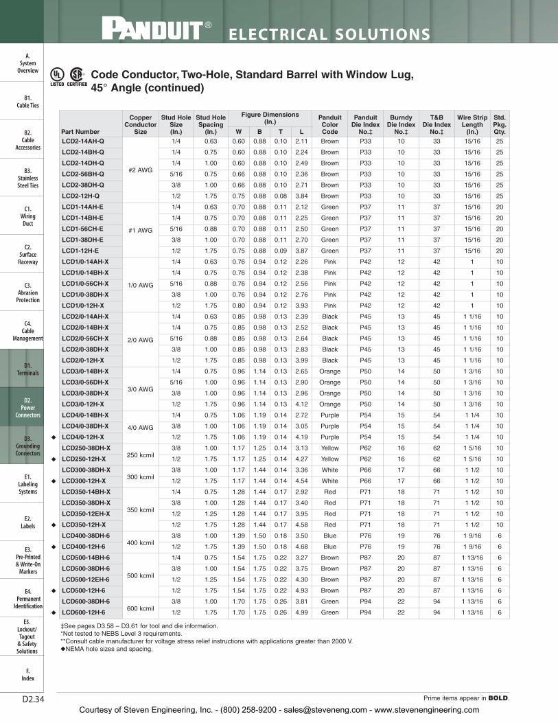
D2.34
ELECTRICAL SOLUTIONS
Prime items appear in BOLD.
B2.Cable
Accessories
C1.Wiring
Duct
C3.Abrasion
Protection
C4.Cable
Management
D1.Terminals
D2.Power
Connectors
E1.LabelingSystems
E2.Labels
E3.Pre-Printed & Write-On
Markers
F.Index
B3.StainlessSteel Ties
C2.Surface
Raceway
E5.Lockout/Tagout
& SafetySolutions
B1.Cable Ties
A.System
Overview
D3.GroundingConnectors
E4.Permanent
Identification
Code Conductor, Two-Hole, Standard Barrel with Window Lug,45° Angle (continued)
‡See pages D3.58 – D3.61 for tool and die information.*Not tested to NEBS Level 3 requirements.**Consult cable manufacturer for voltage stress relief instructions with applications greater than 2000 V.◆NEMA hole sizes and spacing.
LTBW
Std.Pkg.Qty.
Wire Strip Length
(In.)
T&B Die Index
No.‡
Burndy Die Index
No.‡
Panduit Die Index
No.‡
Panduit Color Code
Figure Dimensions (In.)
Stud HoleSpacing
(In.)
Stud HoleSize(In.)
CopperConductor
SizePart NumberLCD2-14AH-Q
#2 AWG
1/4 0.63 0.60 0.88 0.10 2.11 Brown P33 10 33 15/16 25
LCD2-14BH-Q 1/4 0.75 0.60 0.88 0.10 2.24 Brown P33 10 33 15/16 25
LCD2-14DH-Q 1/4 1.00 0.60 0.88 0.10 2.49 Brown P33 10 33 15/16 25
LCD2-56BH-Q 5/16 0.75 0.66 0.88 0.10 2.36 Brown P33 10 33 15/16 25
LCD2-38DH-Q 3/8 1.00 0.66 0.88 0.10 2.71 Brown P33 10 33 15/16 25
LCD2-12H-Q 1/2 1.75 0.75 0.88 0.08 3.84 Brown P33 10 33 15/16 25
LCD1-14AH-E
#1 AWG
1/4 0.63 0.70 0.88 0.11 2.12 Green P37 11 37 15/16 20
LCD1-14BH-E 1/4 0.75 0.70 0.88 0.11 2.25 Green P37 11 37 15/16 20
LCD1-56CH-E 5/16 0.88 0.70 0.88 0.11 2.50 Green P37 11 37 15/16 20
LCD1-38DH-E 3/8 1.00 0.70 0.88 0.11 2.70 Green P37 11 37 15/16 20
LCD1-12H-E 1/2 1.75 0.75 0.88 0.09 3.87 Green P37 11 37 15/16 20
LCD1/0-14AH-X
1/0 AWG
1/4 0.63 0.76 0.94 0.12 2.26 Pink P42 12 42 1 10
LCD1/0-14BH-X 1/4 0.75 0.76 0.94 0.12 2.38 Pink P42 12 42 1 10
LCD1/0-56CH-X 5/16 0.88 0.76 0.94 0.12 2.56 Pink P42 12 42 1 10
LCD1/0-38DH-X 3/8 1.00 0.76 0.94 0.12 2.76 Pink P42 12 42 1 10
LCD1/0-12H-X 1/2 1.75 0.80 0.94 0.12 3.93 Pink P42 12 42 1 10
LCD2/0-14AH-X
2/0 AWG
1/4 0.63 0.85 0.98 0.13 2.39 Black P45 13 45 1 1/16 10
LCD2/0-14BH-X 1/4 0.75 0.85 0.98 0.13 2.52 Black P45 13 45 1 1/16 10
LCD2/0-56CH-X 5/16 0.88 0.85 0.98 0.13 2.64 Black P45 13 45 1 1/16 10
LCD2/0-38DH-X 3/8 1.00 0.85 0.98 0.13 2.83 Black P45 13 45 1 1/16 10
LCD2/0-12H-X 1/2 1.75 0.85 0.98 0.13 3.99 Black P45 13 45 1 1/16 10
LCD3/0-14BH-X
3/0 AWG
1/4 0.75 0.96 1.14 0.13 2.65 Orange P50 14 50 1 3/16 10
LCD3/0-56DH-X 5/16 1.00 0.96 1.14 0.13 2.90 Orange P50 14 50 1 3/16 10
LCD3/0-38DH-X 3/8 1.00 0.96 1.14 0.13 2.96 Orange P50 14 50 1 3/16 10
LCD3/0-12H-X 1/2 1.75 0.96 1.14 0.13 4.12 Orange P50 14 50 1 3/16 10
LCD4/0-14BH-X
4/0 AWG
1/4 0.75 1.06 1.19 0.14 2.72 Purple P54 15 54 1 1/4 10
LCD4/0-38DH-X 3/8 1.00 1.06 1.19 0.14 3.05 Purple P54 15 54 1 1/4 10
◆ LCD4/0-12H-X 1/2 1.75 1.06 1.19 0.14 4.19 Purple P54 15 54 1 1/4 10
LCD250-38DH-X250 kcmil
3/8 1.00 1.17 1.25 0.14 3.13 Yellow P62 16 62 1 5/16 10
◆ LCD250-12H-X 1/2 1.75 1.17 1.25 0.14 4.27 Yellow P62 16 62 1 5/16 10
LCD300-38DH-X300 kcmil
3/8 1.00 1.17 1.44 0.14 3.36 White P66 17 66 1 1/2 10
◆ LCD300-12H-X 1/2 1.75 1.17 1.44 0.14 4.54 White P66 17 66 1 1/2 10
LCD350-14BH-X
350 kcmil
1/4 0.75 1.28 1.44 0.17 2.92 Red P71 18 71 1 1/2 10
LCD350-38DH-X 3/8 1.00 1.28 1.44 0.17 3.40 Red P71 18 71 1 1/2 10
LCD350-12EH-X 1/2 1.25 1.28 1.44 0.17 3.95 Red P71 18 71 1 1/2 10
◆ LCD350-12H-X 1/2 1.75 1.28 1.44 0.17 4.58 Red P71 18 71 1 1/2 10
LCD400-38DH-6400 kcmil
3/8 1.00 1.39 1.50 0.18 3.50 Blue P76 19 76 1 9/16 6
◆ LCD400-12H-6 1/2 1.75 1.39 1.50 0.18 4.68 Blue P76 19 76 1 9/16 6
LCD500-14BH-6
500 kcmil
1/4 0.75 1.54 1.75 0.22 3.27 Brown P87 20 87 1 13/16 6
LCD500-38DH-6 3/8 1.00 1.54 1.75 0.22 3.75 Brown P87 20 87 1 13/16 6
LCD500-12EH-6 1/2 1.25 1.54 1.75 0.22 4.30 Brown P87 20 87 1 13/16 6
◆ LCD500-12H-6 1/2 1.75 1.54 1.75 0.22 4.93 Brown P87 20 87 1 13/16 6
LCD600-38DH-6600 kcmil
3/8 1.00 1.70 1.75 0.26 3.81 Green P94 22 94 1 13/16 6
◆ LCD600-12H-6 1/2 1.75 1.70 1.75 0.26 4.99 Green P94 22 94 1 13/16 6
Courtesy of Steven Engineering, Inc. - (800) 258-9200 - [email protected] - www.stevenengineering.com

D2.35For technical assistance in the U.S., call 866-405-6654 (outside the U.S., see inside back cover for directory)
ELECTRICAL SOLUTIONS
B2.Cable
Accessories
C1.Wiring
Duct
C3.Abrasion
Protection
C4.Cable
Management
D1.Terminals
D2.Power
Connectors
E1.LabelingSystems
E2.Labels
E3.Pre-Printed & Write-On
Markers
F.Index
B3.StainlessSteel Ties
C2.Surface
Raceway
E5.Lockout/Tagout
& SafetySolutions
B1.Cable Ties
A.System
Overview
D3.GroundingConnectors
E4.Permanent
Identification
Code Conductor, Two-Hole, Standard Barrel with Window Lug, 90° Angle
• Color-coded barrels marked with Panduit and specified competitordie index numbers for proper crimp die selection
• Inspection window to visually assure full conductor insertion
• Tin-plated to inhibit corrosion
• UL Listed and CSA Certified to 35 KV** and temperature rated to90°C when crimped with Panduit and specified competitor crimpingtools and dies
• UL Listed and CSA Certified for wide wire range-taking capabilitywhen crimped with Panduit® Uni-Die ™ Dieless Crimping Tools‡
• Tested by Telcordia – meets NEBS Level 3
• American Bureau of Shipping approved
• Available with NEMA hole sizes and spacing
INSPECTIONWINDOW
HOLESPACING
W
T
B
L
90˚
For Use with Stranded Copper Conductors
Type LCD-F
‡See pages D3.58 – D3.61 for tool and die information.*Not tested to NEBS Level 3 requirements.**Consult cable manufacturer for voltage stress relief instructions with applications greater than 2000 V.
Table continues on page D2.36
Part Number
CopperConductor
Size
Stud HoleSize(In.)
Stud HoleSpacing
(In.)
Figure Dimensions (In.)
PanduitColor Code
Panduit Die Index
No.‡
Burndy Die Index
No.‡
T&BDie Index
No.‡
Wire StripLength
(In.)
Std.Pkg.Qty.W B T L
LCD10-10AF-L* #14 – #10AWG STR,#12 – #10AWG SOL
#10 0.63 0.38 0.38 0.06 1.47 — — — — 7/16 50
LCD10-14AF-L* 1/4 0.63 0.42 0.38 0.05 1.56 — — — — 7/16 50
LCD10-38DF-L* 3/8 1.00 0.56 0.38 0.04 2.16 — — — — 7/16 50
LCD8-10AF-L
#8 AWG
#10 0.63 0.41 0.56 0.08 1.53 Red P21 49 21 5/8 50
LCD8-14AF-L 1/4 0.63 0.48 0.56 0.07 1.62 Red P21 49 21 5/8 50
LCD8-14BF-L 1/4 0.75 0.48 0.56 0.07 1.74 Red P21 49 21 5/8 50
LCD8-14DF-L 1/4 1.00 0.48 0.56 0.07 1.99 Red P21 49 21 5/8 50
LCD8-38DF-L 3/8 1.00 0.63 0.56 0.05 2.21 Red P21 49 21 5/8 50
LCD6-10AF-L
#6 AWG
#10 0.63 0.46 0.81 0.08 1.57 Blue P24 7 24 7/8 50
LCD6-10BF-L #10 0.75 0.46 0.81 0.08 1.69 Blue P24 7 24 7/8 50
LCD6-10DF-L #10 1.00 0.46 0.81 0.08 1.94 Blue P24 7 24 7/8 50
LCD6-14AF-L 1/4 0.63 0.48 0.81 0.08 1.66 Blue P24 7 24 7/8 50
LCD6-14BF-L 1/4 0.75 0.48 0.81 0.08 1.78 Blue P24 7 24 7/8 50
LCD6-14DF-L 1/4 1.00 0.48 0.81 0.08 2.03 Blue P24 7 24 7/8 50
LCD6-56DF-L 5/16 1.00 0.56 0.81 0.07 2.15 Blue P24 7 24 7/8 50
LCD6-38DF-L 3/8 1.00 0.62 0.81 0.06 2.25 Blue P24 7 24 7/8 50
LCD4-10AF-L
#4 – #3AWG STR,
#2 AWGSOL
#10 0.63 0.55 0.81 0.09 1.65 Gray P29 8 29 7/8 50
LCD4-10BF-L #10 0.75 0.55 0.81 0.09 1.78 Gray P29 8 29 7/8 50
LCD4-14AF-L 1/4 0.63 0.55 0.81 0.09 1.74 Gray P29 8 29 7/8 50
LCD4-14BF-L 1/4 0.75 0.55 0.81 0.09 1.87 Gray P29 8 29 7/8 50
LCD4-14DF-L 1/4 1.00 0.55 0.81 0.09 2.12 Gray P29 8 29 7/8 50
LCD4-38DF-L 3/8 1.00 0.62 0.81 0.08 2.34 Gray P29 8 29 7/8 50
Courtesy of Steven Engineering, Inc. - (800) 258-9200 - [email protected] - www.stevenengineering.com

D2.36
ELECTRICAL SOLUTIONS
Order number of pieces required, in multiples of Standard Package Quantity. Prime items appear in BOLD.
B2.Cable
Accessories
C1.Wiring
Duct
C3.Abrasion
Protection
C4.Cable
Management
D1.Terminals
D2.Power
Connectors
E1.LabelingSystems
E2.Labels
E3.Pre-Printed & Write-On
Markers
F.Index
B3.StainlessSteel Ties
C2.Surface
Raceway
E5.Lockout/Tagout
& SafetySolutions
B1.Cable Ties
A.System
Overview
D3.GroundingConnectors
E4.Permanent
Identification
‡See pages D3.58 – D3.61 for tool and die information.**Consult cable manufacturer for voltage stress relief instructions with applications greater than 2000 V.◆NEMA hole sizes and spacing.
Code Conductor, Two-Hole, Standard Barrel with Window Lug,90° Angle (continued)
LTBW
Std.Pkg.Qty.
Wire StripLength
(In.)
T&BDie Index
No.‡
Burndy Die Index
No.‡
Panduit Die Index
No.‡
PanduitColor Code
Figure Dimensions (In.)
Stud HoleSpacing
(In.)
Stud HoleSize(In.)
CopperConductor
SizePart NumberLCD2-14AF-Q
#2 AWG
1/4 0.63 0.60 0.88 0.10 1.86 Brown P33 10 33 15/16 25
LCD2-14BF-Q 1/4 0.75 0.60 0.88 0.10 1.99 Brown P33 10 33 15/16 25
LCD2-14DF-Q 1/4 1.00 0.60 0.88 0.10 2.24 Brown P33 10 33 15/16 25
LCD2-56BF-Q 5/16 0.75 0.66 0.88 0.10 2.11 Brown P33 10 33 15/16 25
LCD2-38DF-Q 3/8 1.00 0.66 0.88 0.10 2.47 Brown P33 10 33 15/16 25
LCD2-12F-Q 1/2 1.75 0.75 0.88 0.08 3.61 Brown P33 10 33 15/16 25
LCD1-14AF-E
#1 AWG
1/4 0.63 0.70 0.88 0.11 1.94 Green P37 11 37 15/16 20
LCD1-14BF-E 1/4 0.75 0.70 0.88 0.11 2.06 Green P37 11 37 15/16 20
LCD1-56CF-E 5/16 0.88 0.70 0.88 0.11 2.31 Green P37 11 37 15/16 20
LCD1-38DF-E 3/8 1.00 0.70 0.88 0.11 2.51 Green P37 11 37 15/16 20
LCD1-12F-E 1/2 1.75 0.75 0.88 0.09 3.68 Green P37 11 37 15/16 20
LCD1/0-14AF-X
1/0 AWG
1/4 0.63 0.76 0.94 0.12 2.08 Pink P42 12 42 1 10
LCD1/0-14BF-X 1/4 0.75 0.76 0.94 0.12 2.20 Pink P42 12 42 1 10
LCD1/0-56CF-X 5/16 0.88 0.76 0.94 0.12 2.38 Pink P42 12 42 1 10
LCD1/0-38DF-X 3/8 1.00 0.76 0.94 0.12 2.58 Pink P42 12 42 1 10
LCD1/0-12F-X 1/2 1.75 0.80 0.94 0.12 3.75 Pink P42 12 42 1 10
LCD2/0-14AF-X
2/0 AWG
1/4 0.63 0.85 0.98 0.13 2.22 Black P45 13 45 1 1/16 10
LCD2/0-14BF-X 1/4 0.75 0.85 0.98 0.13 2.34 Black P45 13 45 1 1/16 10
LCD2/0-56CF-X 5/16 0.88 0.85 0.98 0.13 2.47 Black P45 13 45 1 1/16 10
LCD2/0-38DF-X 3/8 1.00 0.85 0.98 0.13 2.66 Black P45 13 45 1 1/16 10
LCD2/0-12F-X 1/2 1.75 0.85 0.98 0.13 3.82 Black P45 13 45 1 1/16 10
LCD3/0-14BF-X
3/0 AWG
1/4 0.75 0.96 1.14 0.13 2.42 Orange P50 14 50 1 3/16 10
LCD3/0-56DF-X 5/16 1.00 0.96 1.14 0.13 2.67 Orange P50 14 50 1 3/16 10
LCD3/0-38DF-X 3/8 1.00 0.96 1.14 0.13 2.73 Orange P50 14 50 1 3/16 10
LCD3/0-12F-X 1/2 1.75 0.96 1.14 0.13 3.89 Orange P50 14 50 1 3/16 10
LCD4/0-14BF-X
4/0 AWG
1/4 0.75 1.06 1.19 0.14 2.50 Purple P54 15 54 1 1/4 10
LCD4/0-38DF-X 3/8 1.00 1.06 1.19 0.14 2.84 Purple P54 15 54 1 1/4 10
◆ LCD4/0-12F-X 1/2 1.75 1.06 1.19 0.14 3.98 Purple P54 15 54 1 1/4 10
LCD250-38DF-X250 kcmil
3/8 1.00 1.17 1.25 0.14 2.90 Yellow P62 16 62 1 5/16 10
◆ LCD250-12F-X 1/2 1.75 1.17 1.25 0.14 4.04 Yellow P62 16 62 1 5/16 10
LCD300-38DF-X300 kcmil
3/8 1.00 1.19 1.44 0.16 2.88 White P66 17 66 1 1/2 10
◆ LCD300-12F-X 1/2 1.75 1.19 1.44 0.16 4.06 White P66 17 66 1 1/2 10
LCD350-14BF-X
350 kcmil
1/4 0.75 1.28 1.44 0.17 2.46 Red P71 18 71 1 1/2 10
LCD350-38DF-X 3/8 1.00 1.28 1.44 0.17 2.94 Red P71 18 71 1 1/2 10
LCD350-12EF-X 1/2 1.25 1.28 1.44 0.17 3.49 Red P71 18 71 1 1/2 10
◆ LCD350-12F-X 1/2 1.75 1.28 1.44 0.17 4.12 Red P71 18 71 1 1/2 10
LCD400-38DF-6400 kcmil
3/8 1.00 1.39 1.50 0.18 3.02 Blue P76 19 76 1 9/16 6
◆ LCD400-12F-6 1/2 1.75 1.39 1.50 0.18 4.20 Blue P76 19 76 1 9/16 6
LCD500-14BF-6
500 kcmil
1/4 0.75 1.54 1.75 0.22 2.65 Brown P87 20 87 1 13/16 6
LCD500-38DF-6 3/8 1.00 1.54 1.75 0.22 3.13 Brown P87 20 87 1 13/16 6
LCD500-12EF-6 1/2 1.25 1.54 1.75 0.22 3.68 Brown P87 20 87 1 13/16 6
◆ LCD500-12F-6 1/2 1.75 1.54 1.75 0.22 4.31 Brown P87 20 87 1 13/16 6
LCD600-38DF-6600 kcmil
3/8 1.00 1.70 1.75 0.26 3.26 Green P94 22 94 1 13/16 6
◆ LCD600-12F-6 1/2 1.75 1.70 1.75 0.26 4.44 Green P94 22 94 1 13/16 6
Courtesy of Steven Engineering, Inc. - (800) 258-9200 - [email protected] - www.stevenengineering.com
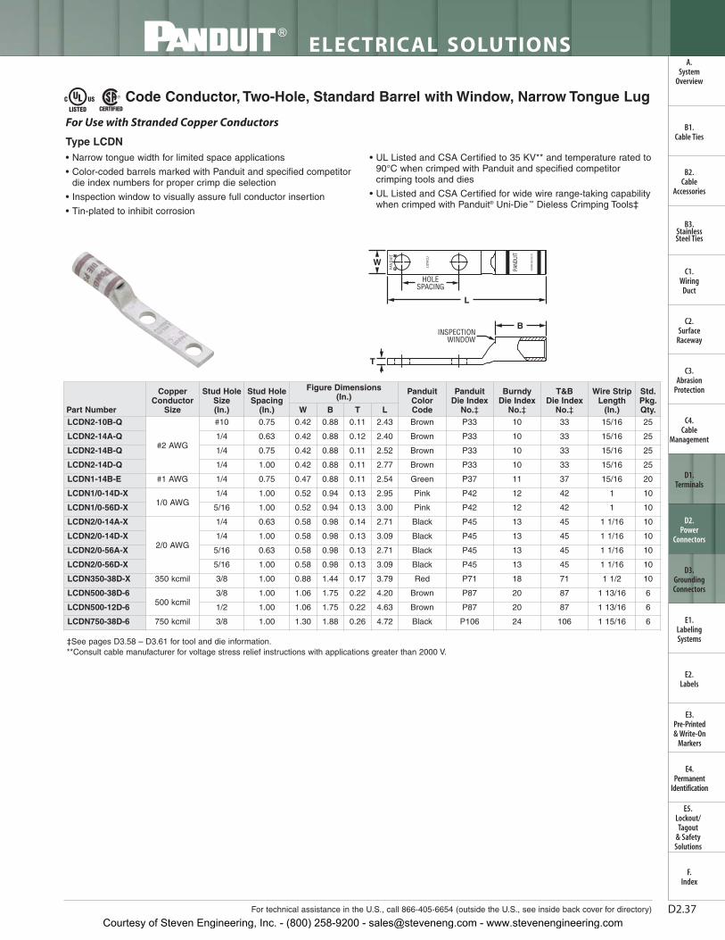
D2.37For technical assistance in the U.S., call 866-405-6654 (outside the U.S., see inside back cover for directory)
ELECTRICAL SOLUTIONS
B2.Cable
Accessories
C1.Wiring
Duct
C3.Abrasion
Protection
C4.Cable
Management
D1.Terminals
D2.Power
Connectors
E1.LabelingSystems
E2.Labels
E3.Pre-Printed & Write-On
Markers
F.Index
B3.StainlessSteel Ties
C2.Surface
Raceway
E5.Lockout/Tagout
& SafetySolutions
B1.Cable Ties
A.System
Overview
D3.GroundingConnectors
E4.Permanent
Identification
Code Conductor, Two-Hole, Standard Barrel with Window, Narrow Tongue Lug
‡See pages D3.58 – D3.61 for tool and die information.**Consult cable manufacturer for voltage stress relief instructions with applications greater than 2000 V.
• Narrow tongue width for limited space applications
• Color-coded barrels marked with Panduit and specified competitordie index numbers for proper crimp die selection
• Inspection window to visually assure full conductor insertion
• Tin-plated to inhibit corrosion
• UL Listed and CSA Certified to 35 KV** and temperature rated to90°C when crimped with Panduit and specified competitorcrimping tools and dies
• UL Listed and CSA Certified for wide wire range-taking capabilitywhen crimped with Panduit® Uni-Die ™ Dieless Crimping Tools‡
For Use with Stranded Copper Conductors
Type LCDN
W
HOLESPACING
L
INSPECTIONWINDOW
B
T
Part Number
CopperConductor
Size
Stud HoleSize(In.)
Stud HoleSpacing
(In.)
Figure Dimensions (In.)
Panduit Color Code
Panduit Die Index
No.‡
Burndy Die Index
No.‡
T&B Die Index
No.‡
Wire StripLength
(In.)
Std.Pkg.Qty.W B T L
LCDN2-10B-Q
#2 AWG
#10 0.75 0.42 0.88 0.11 2.43 Brown P33 10 33 15/16 25
LCDN2-14A-Q 1/4 0.63 0.42 0.88 0.12 2.40 Brown P33 10 33 15/16 25
LCDN2-14B-Q 1/4 0.75 0.42 0.88 0.11 2.52 Brown P33 10 33 15/16 25
LCDN2-14D-Q 1/4 1.00 0.42 0.88 0.11 2.77 Brown P33 10 33 15/16 25
LCDN1-14B-E #1 AWG 1/4 0.75 0.47 0.88 0.11 2.54 Green P37 11 37 15/16 20
LCDN1/0-14D-X1/0 AWG
1/4 1.00 0.52 0.94 0.13 2.95 Pink P42 12 42 1 10
LCDN1/0-56D-X 5/16 1.00 0.52 0.94 0.13 3.00 Pink P42 12 42 1 10
LCDN2/0-14A-X
2/0 AWG
1/4 0.63 0.58 0.98 0.14 2.71 Black P45 13 45 1 1/16 10
LCDN2/0-14D-X 1/4 1.00 0.58 0.98 0.13 3.09 Black P45 13 45 1 1/16 10
LCDN2/0-56A-X 5/16 0.63 0.58 0.98 0.13 2.71 Black P45 13 45 1 1/16 10
LCDN2/0-56D-X 5/16 1.00 0.58 0.98 0.13 3.09 Black P45 13 45 1 1/16 10
LCDN350-38D-X 350 kcmil 3/8 1.00 0.88 1.44 0.17 3.79 Red P71 18 71 1 1/2 10
LCDN500-38D-6500 kcmil
3/8 1.00 1.06 1.75 0.22 4.20 Brown P87 20 87 1 13/16 6
LCDN500-12D-6 1/2 1.00 1.06 1.75 0.22 4.63 Brown P87 20 87 1 13/16 6
LCDN750-38D-6 750 kcmil 3/8 1.00 1.30 1.88 0.26 4.72 Black P106 24 106 1 15/16 6
Courtesy of Steven Engineering, Inc. - (800) 258-9200 - [email protected] - www.stevenengineering.com

D2.38
ELECTRICAL SOLUTIONS
Prime items appear in BOLD.
B2.Cable
Accessories
C1.Wiring
Duct
C3.Abrasion
Protection
C4.Cable
Management
D1.Terminals
D2.Power
Connectors
E1.LabelingSystems
E2.Labels
E3.Pre-Printed & Write-On
Markers
F.Index
B3.StainlessSteel Ties
C2.Surface
Raceway
E5.Lockout/Tagout
& SafetySolutions
B1.Cable Ties
A.System
Overview
D3.GroundingConnectors
E4.Permanent
Identification
Code Conductor, Two-Hole, Standard Barrel with Window, Narrow Tongue Lug, 45°
‡See pages D3.58 – D3.61 for tool and die information.**Consult cable manufacturer for voltage stress relief instructions with applications greater than 2000 V.
HOLESPACING
W
T
L
INSPECTIONWINDOW
45˚
B
• Narrow tongue width for limited space applications
• Color-coded barrels marked with Panduit and specified competitordie index numbers for proper crimp die selection
• Inspection window to visually assure full conductor insertion
• Tin-plated to inhibit corrosion
• UL Listed and CSA Certified to 35 KV** and temperature rated to90°C when crimped with Panduit and specified competitorcrimping tools and dies
• UL Listed and CSA Certified for wide wire range-taking capabilitywhen crimped with Panduit® Uni-Die ™ Dieless Crimping Tools‡
For Use with Stranded Copper Conductors
Type LCDN-H
Part Number
CopperConductor
Size
Stud HoleSize(In.)
Stud HoleSpacing
(In.)
Figure Dimensions (In.) Panduit
Color Code
PanduitDie Index
No.‡
Burndy Die Index
No.‡
T&B Die Index
No.‡
Wire StripLength
(In.)
Std.Pkg.Qty.W B T L
LCDN2-14AH-Q #2 AWG 1/4 0.63 0.42 0.88 0.11 2.12 Brown P33 10 33 15/16 25
LCDN2-14DH-Q #2 AWG 1/4 1.00 0.42 0.88 0.11 2.49 Brown P33 10 33 15/16 25
LCDN1/0-14DH-X 1/0 AWG 1/4 1.00 0.52 0.94 0.13 2.63 Pink P42 12 42 1 10
LCDN1/0-56DH-X 1/0 AWG 5/16 1.00 0.52 0.94 0.13 2.70 Pink P42 12 42 1 10
Courtesy of Steven Engineering, Inc. - (800) 258-9200 - [email protected] - www.stevenengineering.com
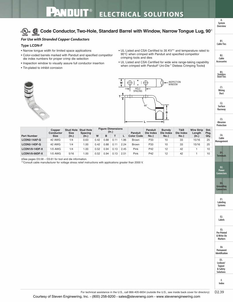
D2.39For technical assistance in the U.S., call 866-405-6654 (outside the U.S., see inside back cover for directory)
ELECTRICAL SOLUTIONS
B2.Cable
Accessories
C1.Wiring
Duct
C3.Abrasion
Protection
C4.Cable
Management
D1.Terminals
D2.Power
Connectors
E1.LabelingSystems
E2.Labels
E3.Pre-Printed & Write-On
Markers
F.Index
B3.StainlessSteel Ties
C2.Surface
Raceway
E5.Lockout/Tagout
& SafetySolutions
B1.Cable Ties
A.System
Overview
D3.GroundingConnectors
E4.Permanent
Identification
Code Conductor,Two-Hole, Standard Barrel with Window, Narrow Tongue Lug, 90°
‡See pages D3.58 – D3.61 for tool and die information.**Consult cable manufacturer for voltage stress relief instructions with applications greater than 2000 V.
• Narrow tongue width for limited space applications
• Color-coded barrels marked with Panduit and specified competitordie index numbers for proper crimp die selection
• Inspection window to visually assure full conductor insertion
• Tin-plated to inhibit corrosion
• UL Listed and CSA Certified to 35 KV** and temperature rated to90°C when crimped with Panduit and specified competitorcrimping tools and dies
• UL Listed and CSA Certified for wide wire range-taking capabilitywhen crimped with Panduit® Uni-Die ™ Dieless Crimping Tools‡
For Use with Stranded Copper Conductors
Type LCDN-F
90˚
INSPECTIONWINDOWW
HOLESPACING
T
B
L
Part Number
CopperConductor
Size
Stud HoleSize(In.)
Stud HoleSpacing
(In.)
Figure Dimensions (In.) Panduit
Color Code
PanduitDie Index
No.‡
Burndy Die Index
No.‡
T&B Die Index
No.‡
Wire StripLength
(In.)
Std.Pkg.Qty.W B T L
LCDN2-14AF-Q #2 AWG 1/4 0.63 0.42 0.88 0.11 1.86 Brown P33 10 33 15/16 25
LCDN2-14DF-Q #2 AWG 1/4 1.00 0.42 0.88 0.11 2.24 Brown P33 10 33 15/16 25
LCDN1/0-14DF-X 1/0 AWG 1/4 1.00 0.52 0.94 0.13 2.45 Pink P42 12 42 1 10
LCDN1/0-56DF-X 1/0 AWG 5/16 1.00 0.52 0.94 0.13 2.51 Pink P42 12 42 1 10
Courtesy of Steven Engineering, Inc. - (800) 258-9200 - [email protected] - www.stevenengineering.com

D2.40
ELECTRICAL SOLUTIONS
Prime items appear in BOLD.
B2.Cable
Accessories
C1.Wiring
Duct
C3.Abrasion
Protection
C4.Cable
Management
D1.Terminals
D2.Power
Connectors
E1.LabelingSystems
E2.Labels
E3.Pre-Printed & Write-On
Markers
F.Index
B3.StainlessSteel Ties
C2.Surface
Raceway
E5.Lockout/Tagout
& SafetySolutions
B1.Cable Ties
A.System
Overview
D3.GroundingConnectors
E4.Permanent
Identification
Code Conductor, Long Blank Tongue, Standard Barrel with Window Lug
‡See pages D3.58 – D3.61 for tool and die information.**Consult cable manufacturer for voltage stress relief instructions with applications greater than 2000 V.
• Color-coded barrels marked with Panduit and specified competitordie index numbers for proper crimp die selection
• Inspection window to visually assure full conductor insertion
• Tin-plated to inhibit corrosion
• UL Recognized and CSA Certified to 35 KV** and temperaturerated to 90°C when crimped with Panduit and specified competitorcrimping tools and dies
L
W
T
INSPECTIONWINDOW
B
For Use with Stranded Copper Conductors
Type LCD-00
Part NumberCopper
Conductor Size
Figure Dimensions (In.)
PanduitColor Code
Panduit Die Index
No.‡
Burndy Die Index
No.‡
T&B Die Index
No.‡
Wire StripLength
(In.)
Std.Pkg.Qty.W B T L
LCD1/0-00-X 1/0 AWG 0.76 0.94 0.12 4.25 Pink P42 12 42 1 10
LCD2/0-00-X 2/0 AWG 0.85 0.98 0.13 4.30 Black P45 13 45 1 1/16 10
LCD3/0-00-X 3/0 AWG 0.96 1.14 0.13 4.50 Orange P50 14 50 1 3/16 10
LCD4/0-00-X 4/0 AWG 1.06 1.19 0.14 4.58 Purple P54 15 54 1 1/4 10
LCD250-00-X 250 kcmil 1.17 1.25 0.14 4.69 Yellow P62 16 62 1 5/16 10
LCD300-00-X 300 kcmil 1.19 1.44 0.16 4.93 White P66 17 66 1 1/2 10
LCD350-00-X 350 kcmil 1.28 1.44 0.17 4.97 Red P71 18 71 1 1/2 10
LCD400-00-6 400 kcmil 1.39 1.50 0.18 5.05 Blue P76 19 76 1 9/16 6
LCD500-00-6 500 kcmil 1.54 1.75 0.22 5.38 Brown P87 20 87 1 13/16 6
LCD600-00-6 600 kcmil 1.70 1.75 0.26 5.43 Green P94 22 94 1 13/16 6
LCD750-00-6 750 kcmil 1.89 1.88 0.26 5.65 Black P106 24 106 1 15/16 6
LCD1000-00-3 1000 kcmil 2.17 1.88 0.32 5.77 White P125 27 125 1 15/16 3
Courtesy of Steven Engineering, Inc. - (800) 258-9200 - [email protected] - www.stevenengineering.com

D2.41For technical assistance in the U.S., call 866-405-6654 (outside the U.S., see inside back cover for directory)
ELECTRICAL SOLUTIONS
B2.Cable
Accessories
C1.Wiring
Duct
C3.Abrasion
Protection
C4.Cable
Management
D1.Terminals
D2.Power
Connectors
E1.LabelingSystems
E2.Labels
E3.Pre-Printed & Write-On
Markers
F.Index
B3.StainlessSteel Ties
C2.Surface
Raceway
E5.Lockout/Tagout
& SafetySolutions
B1.Cable Ties
A.System
Overview
D3.GroundingConnectors
E4.Permanent
Identification
Code Conductor, Two-Hole, Long Barrel Lug
‡See pages D3.62 – D3.65 for tool and die information.**Consult cable manufacturer for voltage stress relief instructions with applications greater than 2000 V.◆NEMA hole sizes and spacing.
• Long barrel maximizes number of crimps and provides premiumwire pull-out strength and electrical performance
• Color-coded barrels marked with Panduit and specified competitordie index numbers for proper crimp die selection
• Enclosed barrel prevents corrosive material from entering barrelwhen used in harsh environments
• Tin-plated to inhibit corrosion
• UL Listed and CSA Certified to 35 KV** and temperature rated to90°C when crimped with Panduit and specified competitorcrimping tools and dies
• UL Listed and CSA Certified for wide wire range-taking capabilitywhen crimped with Panduit® Uni-Die ™ Dieless Crimping Tools‡
• Tested by Telcordia – meets NEBS Level 3
• American Bureau of Shipping approved
• Available with NEMA hole sizes and spacing
For Use with Stranded Copper Conductors
Type LCC
W
HOLESPACING
L
T
B
Table continues on page D2.42
Part Number
CopperConductor
Size
StudHoleSize(In.)
StudHole
Spacing(In.)
Figure Dimensions (In.)
PanduitColorCode
PanduitDie Index
No.‡
BurndyDie Index
No.‡
T&BDie Index
No.‡
Wire StripLength
(In.)
Std.Pkg.Qty.W B T L
LCC8-10A-L
#8 AWG
#10 0.63 0.41 0.70 0.08 2.07 Red P21 49 21 3/4 50
LCC8-14A-L 1/4 0.63 0.48 0.70 0.07 2.16 Red P21 49 21 3/4 50
LCC8-14B-L 1/4 0.75 0.48 0.70 0.07 2.28 Red P21 49 21 3/4 50
LCC8-14D-L 1/4 1.00 0.48 0.70 0.07 2.53 Red P21 49 21 3/4 50
LCC8-38D-L 3/8 1.00 0.60 0.70 0.05 2.75 Red P21 49 21 3/4 50
LCC6-10A-L
#6 AWG
#10 0.63 0.46 1.07 0.08 2.47 Blue P24 7 24 1 1/8 50
LCC6-14A-L 1/4 0.63 0.48 1.07 0.08 2.56 Blue P24 7 24 1 1/8 50
LCC6-14B-L 1/4 0.75 0.48 1.07 0.08 2.68 Blue P24 7 24 1 1/8 50
LCC6-14D-L 1/4 1.00 0.48 1.07 0.08 2.93 Blue P24 7 24 1 1/8 50
LCC6-38D-L 3/8 1.00 0.62 1.07 0.06 3.15 Blue P24 7 24 1 1/8 50
LCC6-12-L 1/2 1.75 0.75 1.07 0.07 4.04 Blue P24 7 24 1 1/8 50
LCC4-14A-L#4 – #3
AWG STR,#2 AWG
SOL
1/4 0.63 0.55 1.05 0.09 2.58 Gray P29 8 29 1 1/8 50
LCC4-14B-L 1/4 0.75 0.55 1.05 0.09 2.70 Gray P29 8 29 1 1/8 50
LCC4-38D-L 3/8 1.00 0.62 1.05 0.08 3.17 Gray P29 8 29 1 1/8 50
LCC4-12-L 1/2 1.75 0.75 1.05 0.07 4.09 Gray P29 8 29 1 1/8 50
LCC2-14A-Q
#2 AWG
1/4 0.63 0.60 1.16 0.10 2.77 Brown P33 10 33 1 1/4 25
LCC2-14B-Q 1/4 0.75 0.60 1.16 0.10 2.89 Brown P33 10 33 1 1/4 25
LCC2-56B-Q 5/16 0.75 0.66 1.16 0.10 3.02 Brown P33 10 33 1 1/4 25
LCC2-56C-Q 5/16 0.88 0.66 1.16 0.10 3.14 Brown P33 10 33 1 1/4 25
LCC2-38D-Q 3/8 1.00 0.66 1.16 0.10 3.34 Brown P33 10 33 1 1/4 25
LCC2-38-Q 3/8 1.75 0.66 1.16 0.10 4.09 Brown P33 10 33 1 1/4 25
LCC2-12-Q 1/2 1.75 0.75 1.16 0.08 4.51 Brown P33 10 33 1 1/4 25
LCC1-14A-E
#1 AWG
1/4 0.63 0.70 1.36 0.11 3.00 Green P37 11 37 1 7/16 20
LCC1-14B-E 1/4 0.75 0.70 1.36 0.11 3.12 Green P37 11 37 1 7/16 20
LCC1-56B-E 5/16 0.75 0.70 1.36 0.11 3.25 Green P37 11 37 1 7/16 20
LCC1-56C-E 5/16 0.88 0.70 1.36 0.11 3.37 Green P37 11 37 1 7/16 20
LCC1-38D-E 3/8 1.00 0.70 1.36 0.11 3.57 Green P37 11 37 1 7/16 20
LCC1-12-E 1/2 1.75 0.75 1.36 0.09 4.74 Green P37 11 37 1 7/16 20
Courtesy of Steven Engineering, Inc. - (800) 258-9200 - [email protected] - www.stevenengineering.com

D2.42
ELECTRICAL SOLUTIONS
Prime items appear in BOLD.
B2.Cable
Accessories
C1.Wiring
Duct
C3.Abrasion
Protection
C4.Cable
Management
D1.Terminals
D2.Power
Connectors
E1.LabelingSystems
E2.Labels
E3.Pre-Printed & Write-On
Markers
F.Index
B3.StainlessSteel Ties
C2.Surface
Raceway
E5.Lockout/Tagout
& SafetySolutions
B1.Cable Ties
A.System
Overview
D3.GroundingConnectors
E4.Permanent
Identification
‡See pages D3.62 – D3.65 for tool and die information.**Consult cable manufacturer for voltage stress relief instructions with applications greater than 2000 V.◆NEMA hole sizes and spacing.
Code Conductor, Two-Hole, Long Barrel Lug (continued)
LTBW
Std.Pkg.Qty.
Wire StripLength
(In.)
T&BDie Index
No.‡
BurndyDie Index
No.‡
PanduitDie Index
No.‡
PanduitColorCode
Figure Dimensions (In.)
StudHole
Spacing(In.)
StudHoleSize(In.)
CopperConductor
SizePart NumberLCC1/0-14A-X
1/0 AWG
1/4 0.63 0.76 1.44 0.12 3.18 Pink P42 12 42 1 1/2 10
LCC1/0-14B-X 1/4 0.75 0.76 1.44 0.12 3.31 Pink P42 12 42 1 1/2 10
LCC1/0-56C-X 5/16 0.88 0.76 1.44 0.12 3.49 Pink P42 12 42 1 1/2 10
LCC1/0-56D-X 5/16 1.00 0.76 1.44 0.12 3.61 Pink P42 12 42 1 1/2 10
LCC1/0-38D-X 3/8 1.00 0.76 1.44 0.12 3.69 Pink P42 12 42 1 1/2 10
LCC1/0-12D-X 1/2 1.00 0.80 1.44 0.12 3.95 Pink P42 12 42 1 1/2 10
LCC1/0-12-X 1/2 1.75 0.80 1.44 0.12 4.86 Pink P42 12 42 1 1/2 10
LCC2/0-14A-X
2/0 AWG
1/4 0.63 0.85 1.50 0.13 3.38 Black P45 13 45 1 9/16 10
LCC2/0-14B-X 1/4 0.75 0.85 1.50 0.13 3.51 Black P45 13 45 1 9/16 10
LCC2/0-56D-X 5/16 1.00 0.85 1.50 0.13 3.76 Black P45 13 45 1 9/16 10
LCC2/0-38D-X 3/8 1.00 0.85 1.50 0.13 3.82 Black P45 13 45 1 9/16 10
LCC2/0-12D-X 1/2 1.00 0.85 1.50 0.13 4.07 Black P45 13 45 1 9/16 10
LCC2/0-12-X 1/2 1.75 0.85 1.50 0.13 4.98 Black P45 13 45 1 9/16 10
LCC3/0-14B-X
3/0 AWG
1/4 0.75 0.96 1.50 0.13 3.56 Orange P50 14 50 1 9/16 10
LCC3/0-38D-X 3/8 1.00 0.96 1.50 0.13 3.87 Orange P50 14 50 1 9/16 10
LCC3/0-12D-X 1/2 1.00 0.96 1.50 0.13 4.12 Orange P50 14 50 1 9/16 10
LCC3/0-12-X 1/2 1.75 0.96 1.50 0.13 5.03 Orange P50 14 50 1 9/16 10
LCC4/0-14B-X
4/0 AWG
1/4 0.75 1.06 1.56 0.14 3.66 Purple P54 15 54 1 5/8 10
LCC4/0-56D-X 5/16 1.00 1.06 1.56 0.14 3.92 Purple P54 15 54 1 5/8 10
LCC4/0-38D-X 3/8 1.00 1.06 1.56 0.14 3.99 Purple P54 15 54 1 5/8 10
LCC4/0-38-X 3/8 1.75 1.06 1.56 0.14 4.74 Purple P54 15 54 1 5/8 10
LCC4/0-12D-X 1/2 1.00 1.06 1.56 0.14 4.22 Purple P54 15 54 1 5/8 10
◆ LCC4/0-12-X 1/2 1.75 1.06 1.56 0.14 5.13 Purple P54 15 54 1 5/8 10
LCC250-38D-X
250 kcmil
3/8 1.00 1.17 1.60 0.14 4.09 Yellow P62 16 62 1 11/16 10
LCC250-12D-X 1/2 1.00 1.17 1.60 0.14 4.32 Yellow P62 16 62 1 11/16 10
◆ LCC250-12-X 1/2 1.75 1.17 1.60 0.14 5.23 Yellow P62 16 62 1 11/16 10
LCC300-38D-X300 kcmil
3/8 1.00 1.19 2.24 0.16 4.76 White P66 17 66 2 5/16 10
◆ LCC300-12-X 1/2 1.75 1.19 2.24 0.16 5.94 White P66 17 66 2 5/16 10
LCC350-14B-X
350 kcmil
1/4 0.75 1.28 2.24 0.17 4.33 Red P71 18 71 2 5/16 10
LCC350-38D-X 3/8 1.00 1.28 2.24 0.17 4.81 Red P71 18 71 2 5/16 10
◆ LCC350-12-X 1/2 1.75 1.28 2.24 0.17 5.99 Red P71 18 71 2 5/16 10
LCC400-14B-6
400 kcmil
1/4 0.75 1.39 2.30 0.18 4.44 Blue P76 19 76 2 3/8 6
LCC400-38D-6 3/8 1.00 1.39 2.30 0.18 4.92 Blue P76 19 76 2 3/8 6
◆ LCC400-12-6 1/2 1.75 1.39 2.30 0.18 6.10 Blue P76 19 76 2 3/8 6
LCC500-14B-6
500 kcmil
1/4 0.75 1.54 2.50 0.22 4.70 Brown P87 20 87 2 9/16 6
LCC500-38D-6 3/8 1.00 1.54 2.50 0.22 5.18 Brown P87 20 87 2 9/16 6
◆ LCC500-12-6 1/2 1.75 1.54 2.50 0.22 6.36 Brown P87 20 87 2 9/16 6
LCC600-38D-6600 kcmil
3/8 1.00 1.70 2.69 0.26 5.45 Green P94 22 94 2 3/4 6
◆ LCC600-12-6 1/2 1.75 1.70 2.69 0.26 6.63 Green P94 22 94 2 3/4 6
LCC750-38D-6750 kcmil
3/8 1.00 1.89 2.87 0.26 6.10 Black P106 24 106 2 15/16 6
◆ LCC750-12-6 1/2 1.75 1.89 2.87 0.26 7.04 Black P106 24 106 2 15/16 6
◆ LCC800-12-6 800 kcmil 1/2 1.75 1.95 2.94 0.29 7.13 Orange P107 25 — 3 6
LCC1000-38D-31000 kcmil
3/8 1.00 2.17 3.00 0.32 6.35 White P125 27 125 3 1/16 3
◆ LCC1000-12-3 1/2 1.75 2.17 3.00 0.32 7.29 White P125 27 125 3 1/16 3
Courtesy of Steven Engineering, Inc. - (800) 258-9200 - [email protected] - www.stevenengineering.com

D2.43For technical assistance in the U.S., call 866-405-6654 (outside the U.S., see inside back cover for directory)
ELECTRICAL SOLUTIONS
B2.Cable
Accessories
C1.Wiring
Duct
C3.Abrasion
Protection
C4.Cable
Management
D1.Terminals
D2.Power
Connectors
E1.LabelingSystems
E2.Labels
E3.Pre-Printed & Write-On
Markers
F.Index
B3.StainlessSteel Ties
C2.Surface
Raceway
E5.Lockout/Tagout
& SafetySolutions
B1.Cable Ties
A.System
Overview
D3.GroundingConnectors
E4.Permanent
Identification
Code Conductor, Two-Hole, Long Barrel Lug, 45° Angle
• Long barrel maximizes number of crimps and provides premiumwire pull-out strength and electrical performance
• Color-coded barrels marked with Panduit and specified competitordie index numbers for proper crimp die selection
• Enclosed barrel prevents corrosive material from entering barrelwhen used in harsh environments
• Tin-plated to inhibit corrosion
• UL Listed and CSA Certified to 35 KV** and temperature rated to90°C when crimped with Panduit and specified competitorcrimping tools and dies
• UL Listed and CSA Certified for wide wire range-taking capabilitywhen crimped with Panduit® Uni-Die ™ Dieless Crimping Tools‡
• Tested by Telcordia – meets NEBS Level 3
• American Bureau of Shipping approved
• Available with NEMA hole sizes and spacing
HOLESPACING
W
T
L
45˚
B
For Use with Stranded Copper Conductors
Type LCC-H
‡See pages D3.62 – D3.65 for tool and die information.**Consult cable manufacturer for voltage stress relief instructions with applications greater than 2000 V.◆NEMA hole sizes and spacing.
Table continues on page D2.44
Part Number
CopperConductor
Size
StudHoleSize(In.)
StudHole
Spacing(In.)
Figure Dimensions (In.)
PanduitColorCode
PanduitDie Index
No.‡
BurndyDie Index
No.‡
T&BDie Index
No.‡
Wire StripLength
(In.)
Std.Pkg.Qty.W B T L
LCC8-10AH-L
#8 AWG
#10 0.63 0.41 0.70 0.08 1.86 Red P21 49 21 3/4 50
LCC8-14AH-L 1/4 0.63 0.48 0.70 0.07 1.94 Red P21 49 21 3/4 50
LCC8-14BH-L 1/4 0.75 0.48 0.70 0.07 2.06 Red P21 49 21 3/4 50
LCC8-14DH-L 1/4 1.00 0.48 0.70 0.07 2.31 Red P21 49 21 3/4 50
LCC8-38DH-L 3/8 1.00 0.60 0.70 0.05 2.52 Red P21 49 21 3/4 50
LCC6-10AH-L
#6 AWG
#10 0.63 0.46 1.07 0.08 2.14 Blue P24 7 24 1 1/8 50
LCC6-14AH-L 1/4 0.63 0.48 1.07 0.08 2.23 Blue P24 7 24 1 1/8 50
LCC6-14BH-L 1/4 0.75 0.48 1.07 0.08 2.35 Blue P24 7 24 1 1/8 50
LCC6-14DH-L 1/4 1.00 0.48 1.07 0.08 2.60 Blue P24 7 24 1 1/8 50
LCC6-38DH-L 3/8 1.00 0.62 1.07 0.06 2.81 Blue P24 7 24 1 1/8 50
LCC4-14AH-L #4 – #3AWG STR,
#2 AWGSOL
1/4 0.63 0.55 1.05 0.09 2.26 Gray P29 8 29 1 1/8 50
LCC4-14BH-L 1/4 0.75 0.55 1.05 0.09 2.38 Gray P29 8 29 1 1/8 50
LCC4-38DH-L 3/8 1.00 0.62 1.05 0.08 2.84 Gray P29 8 29 1 1/8 50
LCC2-14AH-Q
#2 AWG
1/4 0.63 0.60 1.16 0.10 2.38 Brown P33 10 33 1 1/4 25
LCC2-14BH-Q 1/4 0.75 0.60 1.16 0.10 2.50 Brown P33 10 33 1 1/4 25
LCC2-56BH-Q 5/16 0.75 0.66 1.16 0.10 2.62 Brown P33 10 33 1 1/4 25
LCC2-56CH-Q 5/16 0.88 0.66 1.16 0.10 2.75 Brown P33 10 33 1 1/4 25
LCC2-38DH-Q 3/8 1.00 0.66 1.16 0.10 2.95 Brown P33 10 33 1 1/4 25
LCC2-38H-Q 3/8 1.75 0.66 1.16 0.10 3.70 Brown P33 10 33 1 1/4 25
LCC2-12H-Q 1/2 1.75 0.75 1.16 0.08 4.10 Brown P33 10 33 1 1/4 25
Courtesy of Steven Engineering, Inc. - (800) 258-9200 - [email protected] - www.stevenengineering.com

D2.44
ELECTRICAL SOLUTIONS
Prime items appear in BOLD.
B2.Cable
Accessories
C1.Wiring
Duct
C3.Abrasion
Protection
C4.Cable
Management
D1.Terminals
D2.Power
Connectors
E1.LabelingSystems
E2.Labels
E3.Pre-Printed & Write-On
Markers
F.Index
B3.StainlessSteel Ties
C2.Surface
Raceway
E5.Lockout/Tagout
& SafetySolutions
B1.Cable Ties
A.System
Overview
D3.GroundingConnectors
E4.Permanent
Identification
Code Conductor, Two-Hole, Long Barrel Lug, 45° Angle (continued)
‡See pages D3.62 – D3.65 for tool and die information.**Consult cable manufacturer for voltage stress relief instructions with applications greater than 2000 V.◆NEMA hole sizes and spacing.
LTBW
Std.Pkg.Qty.
Wire StripLength
(In.)
T&BDie Index
No.‡
BurndyDie Index
No.‡
PanduitDie Index
No.‡
PanduitColorCode
Figure Dimensions (In.)
StudHole
Spacing(In.)
StudHoleSize(In.)
CopperConductor
SizePart NumberLCC1-14AH-E
#1 AWG
1/4 0.63 0.70 1.36 0.11 2.53 Green P37 11 37 1 7/16 20
LCC1-14BH-E 1/4 0.75 0.70 1.36 0.11 2.66 Green P37 11 37 1 7/16 20
LCC1-56BH-E 5/16 0.75 0.70 1.36 0.11 2.78 Green P37 11 37 1 7/16 20
LCC1-56CH-E 5/16 0.88 0.70 1.36 0.11 2.91 Green P37 11 37 1 7/16 20
LCC1-38DH-E 3/8 1.00 0.70 1.36 0.11 3.11 Green P37 11 37 1 7/16 20
LCC1-12H-E 1/2 1.75 0.75 1.36 0.09 4.27 Green P37 11 37 1 7/16 20
LCC1/0-14AH-X
1/0 AWG
1/4 0.63 0.76 1.44 0.12 2.69 Pink P42 12 42 1 1/2 10
LCC1/0-14BH-X 1/4 0.75 0.76 1.44 0.12 2.81 Pink P42 12 42 1 1/2 10
LCC1/0-56CH-X 5/16 0.88 0.76 1.44 0.12 2.99 Pink P42 12 42 1 1/2 10
LCC1/0-56DH-X 5/16 1.00 0.76 1.44 0.12 3.12 Pink P42 12 42 1 1/2 10
LCC1/0-38DH-X 3/8 1.00 0.76 1.44 0.12 3.19 Pink P42 12 42 1 1/2 10
LCC1/0-12DH-X 1/2 1.00 0.80 1.44 0.12 3.46 Pink P42 12 42 1 1/2 10
LCC1/0-12H-X 1/2 1.75 0.80 1.44 0.12 4.36 Pink P42 12 42 1 1/2 10
LCC2/0-14AH-X
2/0 AWG
1/4 0.63 0.85 1.50 0.13 2.87 Black P45 13 45 1 9/16 10
LCC2/0-14BH-X 1/4 0.75 0.85 1.50 0.13 2.99 Black P45 13 45 1 9/16 10
LCC2/0-56DH-X 5/16 1.00 0.85 1.50 0.13 3.24 Black P45 13 45 1 9/16 10
LCC2/0-38DH-X 3/8 1.00 0.85 1.50 0.13 3.31 Black P45 13 45 1 9/16 10
LCC2/0-12DH-X 1/2 1.00 0.85 1.50 0.13 3.56 Black P45 13 45 1 9/16 10
LCC2/0-12H-X 1/2 1.75 0.85 1.50 0.13 4.47 Black P45 13 45 1 9/16 10
LCC3/0-14BH-X
3/0 AWG
1/4 0.75 0.96 1.50 0.13 3.02 Orange P50 14 50 1 9/16 10
LCC3/0-38DH-X 3/8 1.00 0.96 1.50 0.13 3.33 Orange P50 14 50 1 9/16 10
LCC3/0-12DH-X 1/2 1.00 0.96 1.50 0.13 3.58 Orange P50 14 50 1 9/16 10
LCC3/0-12H-X 1/2 1.75 0.96 1.50 0.13 4.50 Orange P50 14 50 1 9/16 10
LCC4/0-14BH-X
4/0 AWG
1/4 0.75 1.06 1.56 0.14 3.11 Purple P54 15 54 1 5/8 10
LCC4/0-56DH-X 5/16 1.00 1.06 1.56 0.14 3.37 Purple P54 15 54 1 5/8 10
LCC4/0-38DH-X 3/8 1.00 1.06 1.56 0.14 3.44 Purple P54 15 54 1 5/8 10
LCC4/0-38H-X 3/8 1.75 1.06 1.56 0.14 4.19 Purple P54 15 54 1 5/8 10
LCC4/0-12DH-X 1/2 1.00 1.06 1.56 0.14 3.67 Purple P54 15 54 1 5/8 10
◆ LCC4/0-12H-X 1/2 1.75 1.06 1.56 0.14 4.58 Purple P54 15 54 1 5/8 10
LCC250-38DH-X
250 kcmil
3/8 1.00 1.17 1.61 0.14 3.51 Yellow P62 16 62 1 11/16 10
LCC250-12DH-X 1/2 1.00 1.17 1.61 0.14 3.74 Yellow P62 16 62 1 11/16 10
◆ LCC250-12H-X 1/2 1.75 1.17 1.61 0.14 4.65 Yellow P62 16 62 1 11/16 10
LCC300-38DH-X300 kcmil
3/8 1.00 1.19 2.24 0.16 4.05 White P66 17 66 2 5/16 10
◆ LCC300-12H-X 1/2 1.75 1.19 2.24 0.16 5.23 White P66 17 66 2 5/16 10
LCC350-14BH-X
350 kcmil
1/4 0.75 1.28 2.24 0.17 3.61 Red P71 18 71 2 5/16 10
LCC350-38DH-X 3/8 1.00 1.28 2.24 0.17 4.09 Red P71 18 71 2 5/16 10
◆ LCC350-12H-X 1/2 1.75 1.28 2.24 0.17 5.27 Red P71 18 71 2 5/16 10
LCC400-14BH-6
400 kcmil
1/4 0.75 1.39 2.30 0.18 3.70 Blue P76 19 76 2 3/8 6
LCC400-38DH-6 3/8 1.00 1.39 2.30 0.18 4.18 Blue P76 19 76 2 3/8 6
◆ LCC400-12H-6 1/2 1.75 1.39 2.30 0.18 5.36 Blue P76 19 76 2 3/8 6
LCC500-14BH-6
500 kcmil
1/4 0.75 1.54 2.50 0.22 3.91 Brown P87 20 87 2 9/16 6
LCC500-38DH-6 3/8 1.00 1.54 2.50 0.22 4.39 Brown P87 20 87 2 9/16 6
◆ LCC500-12H-6 1/2 1.75 1.54 2.50 0.22 5.57 Brown P87 20 87 2 9/16 6
LCC600-38DH-6600 kcmil
3/8 1.00 1.70 2.69 0.26 4.61 Green P94 22 94 2 3/4 6
◆ LCC600-12H-6 1/2 1.75 1.70 2.69 0.26 5.79 Green P94 22 94 2 3/4 6
Courtesy of Steven Engineering, Inc. - (800) 258-9200 - [email protected] - www.stevenengineering.com
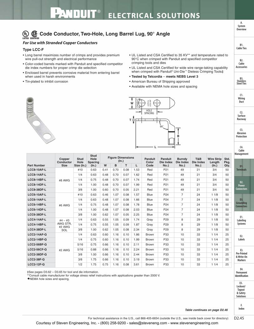
D2.45For technical assistance in the U.S., call 866-405-6654 (outside the U.S., see inside back cover for directory)
ELECTRICAL SOLUTIONS
B2.Cable
Accessories
C1.Wiring
Duct
C3.Abrasion
Protection
C4.Cable
Management
D1.Terminals
D2.Power
Connectors
E1.LabelingSystems
E2.Labels
E3.Pre-Printed & Write-On
Markers
F.Index
B3.StainlessSteel Ties
C2.Surface
Raceway
E5.Lockout/Tagout
& SafetySolutions
B1.Cable Ties
A.System
Overview
D3.GroundingConnectors
E4.Permanent
Identification
Code Conductor, Two-Hole, Long Barrel Lug, 90° Angle
• Long barrel maximizes number of crimps and provides premiumwire pull-out strength and electrical performance
• Color-coded barrels marked with Panduit and specified competitordie index numbers for proper crimp die selection
• Enclosed barrel prevents corrosive material from entering barrelwhen used in harsh environments
• Tin-plated to inhibit corrosion
• UL Listed and CSA Certified to 35 KV** and temperature rated to90°C when crimped with Panduit and specified competitorcrimping tools and dies
• UL Listed and CSA Certified for wide wire range-taking capabilitywhen crimped with Panduit® Uni-Die ™ Dieless Crimping Tools‡
• Tested by Telcordia – meets NEBS Level 3
• American Bureau of Shipping approved
• Available with NEMA hole sizes and spacing
HOLESPACING
W
L
B
T
90˚
For Use with Stranded Copper Conductors
Type LCC-F
‡See pages D3.62 – D3.65 for tool and die information.**Consult cable manufacturer for voltage stress relief instructions with applications greater than 2000 V.◆NEMA hole sizes and spacing.
Table continues on page D2.46
Part Number
CopperConductor
Size
StudHole
Size (In.)
StudHole
Spacing(In.)
Figure Dimensions (In.)
PanduitColorCode
PanduitDie Index
No.‡
BurndyDie Index
No.‡
T&B Die Index
No.‡
Wire StripLength
(In.)
Std.Pkg.Qty.W B T L
LCC8-10AF-L
#8 AWG
#10 0.63 0.41 0.70 0.08 1.53 Red P21 49 21 3/4 50
LCC8-14AF-L 1/4 0.63 0.48 0.70 0.07 1.62 Red P21 49 21 3/4 50
LCC8-14BF-L 1/4 0.75 0.48 0.70 0.07 1.74 Red P21 49 21 3/4 50
LCC8-14DF-L 1/4 1.00 0.48 0.70 0.07 1.99 Red P21 49 21 3/4 50
LCC8-38DF-L 3/8 1.00 0.60 0.70 0.05 2.21 Red P21 49 21 3/4 50
LCC6-10AF-L
#6 AWG
#10 0.63 0.46 1.07 0.08 1.57 Blue P24 7 24 1 1/8 50
LCC6-14AF-L 1/4 0.63 0.48 1.07 0.08 1.66 Blue P24 7 24 1 1/8 50
LCC6-14BF-L 1/4 0.75 0.48 1.07 0.08 1.78 Blue P24 7 24 1 1/8 50
LCC6-14DF-L 1/4 1.00 0.48 1.07 0.08 2.03 Blue P24 7 24 1 1/8 50
LCC6-38DF-L 3/8 1.00 0.62 1.07 0.05 2.25 Blue P24 7 24 1 1/8 50
LCC4-14AF-L #4 – #3AWG STR,
#2 AWGSOL
1/4 0.63 0.55 1.05 0.09 1.74 Gray P29 8 29 1 1/8 50
LCC4-14BF-L 1/4 0.75 0.55 1.05 0.09 1.87 Gray P29 8 29 1 1/8 50
LCC4-38DF-L 3/8 1.00 0.62 1.05 0.08 2.34 Gray P29 8 29 1 1/8 50
LCC2-14AF-Q
#2 AWG
1/4 0.63 0.60 1.16 0.10 1.86 Brown P33 10 33 1 1/4 25
LCC2-14BF-Q 1/4 0.75 0.60 1.16 0.10 1.99 Brown P33 10 33 1 1/4 25
LCC2-56BF-Q 5/16 0.75 0.66 1.16 0.10 2.11 Brown P33 10 33 1 1/4 25
LCC2-56CF-Q 5/16 0.88 0.66 1.16 0.10 2.24 Brown P33 10 33 1 1/4 25
LCC2-38DF-Q 3/8 1.00 0.66 1.16 0.10 2.44 Brown P33 10 33 1 1/4 25
LCC2-38F-Q 3/8 1.75 0.66 1.16 0.10 3.19 Brown P33 10 33 1 1/4 25
LCC2-12F-Q 1/2 1.75 0.75 1.16 0.08 3.61 Brown P33 10 33 1 1/4 25
Courtesy of Steven Engineering, Inc. - (800) 258-9200 - [email protected] - www.stevenengineering.com

D2.46
ELECTRICAL SOLUTIONS
Prime items appear in BOLD.
B2.Cable
Accessories
C1.Wiring
Duct
C3.Abrasion
Protection
C4.Cable
Management
D1.Terminals
D2.Power
Connectors
E1.LabelingSystems
E2.Labels
E3.Pre-Printed & Write-On
Markers
F.Index
B3.StainlessSteel Ties
C2.Surface
Raceway
E5.Lockout/Tagout
& SafetySolutions
B1.Cable Ties
A.System
Overview
D3.GroundingConnectors
E4.Permanent
Identification
Code Conductor, Two-Hole, Long Barrel Lug, 90° Angle (continued)
‡See pages D3.62 – D3.65 for tool and die information.**Consult cable manufacturer for voltage stress relief instructions with applications greater than 2000 V.◆NEMA hole sizes and spacing.
LTBW
Std.Pkg.Qty.
Wire StripLength
(In.)
T&B Die Index
No.‡
BurndyDie Index
No.‡
PanduitDie Index
No.‡
PanduitColorCode
Figure Dimensions (In.)
StudHole
Spacing(In.)
StudHole
Size (In.)
CopperConductor
SizePart NumberLCC1-14AF-E
#1 AWG
1/4 0.63 0.70 1.36 0.11 1.94 Green P37 11 37 1 7/16 20
LCC1-14BF-E 1/4 0.75 0.70 1.36 0.11 2.06 Green P37 11 37 1 7/16 20
LCC1-56BF-E 5/16 0.75 0.70 1.36 0.11 2.19 Green P37 11 37 1 7/16 20
LCC1-56CF-E 5/16 0.88 0.70 1.36 0.11 2.31 Green P37 11 37 1 7/16 20
LCC1-38DF-E 3/8 1.00 0.70 1.36 0.11 2.51 Green P37 11 37 1 7/16 20
LCC1-12F-E 1/2 1.75 0.75 1.36 0.09 3.68 Green P37 11 37 1 7/16 20
LCC1/0-14AF-X
1/0 AWG
1/4 0.63 0.76 1.44 0.12 2.08 Pink P42 12 42 1 1/2 10
LCC1/0-14BF-X 1/4 0.75 0.76 1.44 0.12 2.20 Pink P42 12 42 1 1/2 10
LCC1/0-56CF-X 5/16 0.88 0.76 1.44 0.12 2.38 Pink P42 12 42 1 1/2 10
LCC1/0-56DF-X 5/16 1.00 0.76 1.44 0.12 2.51 Pink P42 12 42 1 1/2 10
LCC1/0-38DF-X 3/8 1.00 0.76 1.44 0.12 2.58 Pink P42 12 42 1 1/2 10
LCC1/0-12DF-X 1/2 1.00 0.80 1.44 0.12 2.85 Pink P42 12 42 1 1/2 10
LCC1/0-12F-X 1/2 1.75 0.80 1.44 0.12 3.75 Pink P42 12 42 1 1/2 10
LCC2/0-14AF-X
2/0 AWG
1/4 0.63 0.85 1.50 0.13 2.22 Black P45 13 45 1 9/16 10
LCC2/0-14BF-X 1/4 0.75 0.85 1.50 0.13 2.34 Black P45 13 45 1 9/16 10
LCC2/0-56DF-X 5/16 1.00 0.85 1.50 0.13 2.59 Black P45 13 45 1 9/16 10
LCC2/0-38DF-X 3/8 1.00 0.85 1.50 0.13 2.66 Black P45 13 45 1 9/16 10
LCC2/0-12DF-X 1/2 1.00 0.85 1.50 0.13 2.85 Black P45 13 45 1 9/16 10
LCC2/0-12F-X 1/2 1.75 0.85 1.50 0.13 3.82 Black P45 13 45 1 9/16 10
LCC3/0-14BF-X
3/0 AWG
1/4 0.75 0.96 1.50 0.13 2.42 Orange P50 14 50 1 9/16 10
LCC3/0-38DF-X 3/8 1.00 0.96 1.50 0.13 2.73 Orange P50 14 50 1 9/16 10
LCC3/0-12DF-X 1/2 1.00 0.96 1.50 0.13 2.98 Orange P50 14 50 1 9/16 10
LCC3/0-12F-X 1/2 1.75 0.96 1.50 0.13 3.89 Orange P50 14 50 1 9/16 10
LCC4/0-14BF-X
4/0 AWG
1/4 0.75 1.06 1.56 0.14 2.50 Purple P54 15 54 1 5/8 10
LCC4/0-56DF-X 5/16 1.00 1.06 1.56 0.14 2.77 Purple P54 15 54 1 5/8 10
LCC4/0-38DF-X 3/8 1.00 1.06 1.56 0.14 2.84 Purple P54 15 54 1 5/8 10
LCC4/0-38F-X 3/8 1.75 1.06 1.56 0.14 3.59 Purple P54 15 54 1 5/8 10
LCC4/0-12DF-X 1/2 1.00 1.06 1.56 0.14 3.07 Purple P54 15 54 1 5/8 10
◆ LCC4/0-12F-X 1/2 1.75 1.06 1.56 0.14 3.98 Purple P54 15 54 1 5/8 10
LCC250-38DF-X
250 kcmil
3/8 1.00 1.17 1.61 0.14 2.90 Yellow P62 16 62 1 11/16 10
LCC250-12DF-X 1/2 1.00 1.17 1.61 0.14 3.13 Yellow P62 16 62 1 11/16 10
◆ LCC250-12F-X 1/2 1.75 1.17 1.61 0.14 4.04 Yellow P62 16 62 1 11/16 10
LCC300-38DF-X300 kcmil
3/8 1.00 1.19 2.24 0.16 2.88 White P66 17 66 2 5/16 10
◆ LCC300-12F-X 1/2 1.75 1.19 2.24 0.16 4.06 White P66 17 66 2 5/16 10
LCC350-14BF-X
350 kcmil
1/4 0.75 1.28 2.24 0.17 2.46 Red P71 18 71 2 5/16 10
LCC350-38DF-X 3/8 1.00 1.28 2.24 0.17 2.94 Red P71 18 71 2 5/16 10
◆ LCC350-12F-X 1/2 1.75 1.28 2.24 0.17 4.12 Red P71 18 71 2 5/16 10
LCC400-14BF-6
400 kcmil
1/4 0.75 1.39 2.30 0.18 2.54 Blue P76 19 76 2 3/8 6
LCC400-38DF-6 3/8 1.00 1.39 2.30 0.18 3.02 Blue P76 19 76 2 3/8 6
◆ LCC400-12F-6 1/2 1.75 1.39 2.30 0.18 4.20 Blue P76 19 76 2 3/8 6
LCC500-14BF-6
500 kcmil
1/4 0.75 1.54 2.50 0.22 2.65 Brown P87 20 87 2 9/16 6
LCC500-38DF-6 3/8 1.00 1.54 2.50 0.22 3.13 Brown P87 20 87 2 9/16 6
◆ LCC500-12F-6 1/2 1.75 1.54 2.50 0.22 4.31 Brown P87 20 87 2 9/16 6
LCC600-38DF-6600 kcmil
3/8 1.00 1.70 2.69 0.26 3.26 Green P94 22 94 2 3/4 6
◆ LCC600-12F-6 1/2 1.75 1.70 2.69 0.26 4.44 Green P94 22 94 2 3/4 6
Courtesy of Steven Engineering, Inc. - (800) 258-9200 - [email protected] - www.stevenengineering.com
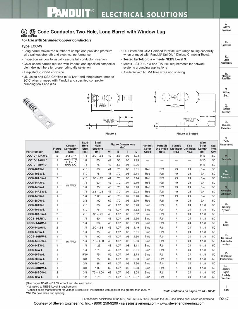
D2.47For technical assistance in the U.S., call 866-405-6654 (outside the U.S., see inside back cover for directory)
ELECTRICAL SOLUTIONS
B2.Cable
Accessories
C1.Wiring
Duct
C3.Abrasion
Protection
C4.Cable
Management
D1.Terminals
D2.Power
Connectors
E1.LabelingSystems
E2.Labels
E3.Pre-Printed & Write-On
Markers
F.Index
B3.StainlessSteel Ties
C2.Surface
Raceway
E5.Lockout/Tagout
& SafetySolutions
B1.Cable Ties
A.System
Overview
D3.GroundingConnectors
E4.Permanent
Identification
Code Conductor, Two-Hole, Long Barrel with Window Lug
Part NumberFigure
No.
CopperConductor
Size
StudHoleSize(In.)
StudHole
Spacing(In.)
Figure Dimensions (In.)
PanduitColorCode
PanduitDie Index
No.‡
BurndyDie Index
No.‡
T&B Die Index
No.‡
WireStrip
Length(In.)
Std.Pkg.Qty.W B T L
LCC10-14JAW-L* 2 #14 – 10AWG STR,#12 – 10
AWG SOL
1/4 .50 – .63 .42 .53 .05 1.93 — — — — 9/16 50
LCC10-14AW-L* 1 1/4 .63 .42 .53 .05 1.93 — — — — 9/16 50
LCC10-14BW-L* 1 1/4 .75 .42 .53 .05 2.06 — — — — 9/16 50
LCC8-10AW-L 1
#8 AWG
#10 .63 .41 .70 .08 2.01 Red P21 49 21 3/4 50
LCC8-10BW-L 1 #10 .75 .41 .70 .08 2.14 Red P21 49 21 3/4 50
LCC8-10ABW-L 2 #10 .63 – .75 .41 .70 .08 2.14 Red P21 49 21 3/4 50
LCC8-14AW-L 1 1/4 .63 .48 .70 .07 2.10 Red P21 49 21 3/4 50
LCC8-14BW-L 1 1/4 .75 .48 .70 .07 2.23 Red P21 49 21 3/4 50
LCC8-14ABW-L 2 1/4 .63 – .75 .48 .70 .07 2.23 Red P21 49 21 3/4 50
LCC8-14DW-L 1 1/4 1.00 .48 .70 .07 2.48 Red P21 49 21 3/4 50
LCC8-38DW-L 1 3/8 1.00 .60 .70 .05 2.70 Red P21 49 21 3/4 50
LCC6-10AW-L 1
#6 AWG
#10 .63 .46 1.07 .08 2.40 Blue P24 7 24 1 1/8 50
LCC6-10BW-L 1 #10 .75 .46 1.07 .08 2.52 Blue P24 7 24 1 1/8 50
LCC6-10ABW-L 2 #10 .63 – .75 .46 1.07 .08 2.52 Blue P24 7 24 1 1/8 50
LCC6-14JW-L 1 1/4 .50 .48 1.07 .08 2.36 Blue P24 7 24 1 1/8 50
LCC6-14AW-L 1 1/4 .63 .48 1.07 .08 2.49 Blue P24 7 24 1 1/8 50
LCC6-14JAW-L 2 1/4 .50 – .63 .48 1.07 .08 2.49 Blue P24 7 24 1 1/8 50
LCC6-14BW-L 1 1/4 .75 .48 1.07 .08 2.61 Blue P24 7 24 1 1/8 50
LCC6-14DW-L 1 1/4 1.00 .48 1.07 .08 2.86 Blue P24 7 24 1 1/8 50
LCC6-14BDW-L 2 1/4 .75 – 1.00 .48 1.07 .08 2.86 Blue P24 7 24 1 1/8 50
LCC6-14EW-L 1 1/4 1.25 .48 1.07 .08 3.11 Blue P24 7 24 1 1/8 50
LCC6-14W-L 1 1/4 1.75 .48 1.07 .08 3.61 Blue P24 7 24 1 1/8 50
LCC6-56BW-L 1 5/16 .75 .56 1.07 .07 2.73 Blue P24 7 24 1 1/8 50
LCC6-38BW-L 1 3/8 .75 .62 1.07 .06 2.83 Blue P24 7 24 1 1/8 50
LCC6-38CW-L 1 3/8 .88 .62 1.07 .06 2.96 Blue P24 7 24 1 1/8 50
LCC6-38DW-L 1 3/8 1.00 .62 1.07 .06 3.08 Blue P24 7 24 1 1/8 50
LCC6-38BDW-L 2 3/8 .75 – 1.00 .62 1.07 .06 3.08 Blue P24 7 24 1 1/8 50
LCC6-12W-L 1 1/2 1.75 .75 1.07 0.07 3.97 Blue P24 7 24 1 1/8 50
• Long barrel maximizes number of crimps and provides premiumwire pull-out strength and electrical performance
• Inspection window to visually assure full conductor insertion
• Color-coded barrels marked with Panduit and specified competitordie index numbers for proper crimp die selection
• Tin-plated to inhibit corrosion
• UL Listed and CSA Certified to 35 KV** and temperature rated to90°C when crimped with Panduit and specified competitorcrimping tools and dies
• UL Listed and CSA Certified for wide wire range-taking capabilitywhen crimped with Panduit® Uni-Die ™ Dieless Crimping Tools‡
• Tested by Telcordia – meets NEBS Level 3
• Meets J-STD-607-A and TIA-942 requirements for networksystems grounding applications
• Available with NEMA hole sizes and spacing
W
HOLESPACING
T
L
INSPECTIONWINDOW
B
For Use with Stranded Copper Conductors
Type LCC-W
‡See pages D3.62 – D3.65 for tool and die information.*Not tested to NEBS Level 3 requirements.**Consult cable manufacturer for voltage stress relief instructions with applications greater than 2000 V.◆NEMA hole sizes and spacing.
W
HOLESPACING
L
BINSPECTION
WINDOW
T
Figure 1 Figure 2: Slotted
Table continues on pages D2.48 – D2.49
Courtesy of Steven Engineering, Inc. - (800) 258-9200 - [email protected] - www.stevenengineering.com

D2.48
ELECTRICAL SOLUTIONS
Prime items appear in BOLD.
B2.Cable
Accessories
C1.Wiring
Duct
C3.Abrasion
Protection
C4.Cable
Management
D1.Terminals
D2.Power
Connectors
E1.LabelingSystems
E2.Labels
E3.Pre-Printed & Write-On
Markers
F.Index
B3.StainlessSteel Ties
C2.Surface
Raceway
E5.Lockout/Tagout
& SafetySolutions
B1.Cable Ties
A.System
Overview
D3.GroundingConnectors
E4.Permanent
Identification
LTBW
Std.Pkg.Qty.
WireStrip
Length(In.)
T&B Die Index
No.‡
BurndyDie Index
No.‡
PanduitDie Index
No.‡
PanduitColorCode
Figure Dimensions (In.)
StudHole
Spacing(In.)
StudHoleSize(In.)
CopperConductor
SizeFigure
No.Part NumberLCC4-10AW-L 1
#4 – 3 AWGSTR, #2
AWG SOL
#10 .63 .55 1.05 .09 2.40 Gray P29 8 29 1 1/8 50
LCC4-10BW-L 1 #10 .75 .55 1.05 .09 2.53 Gray P29 8 29 1 1/8 50
LCC4-14AW-L 1 1/4 .63 .55 1.05 .09 2.50 Gray P29 8 29 1 1/8 50
LCC4-14BW-L 1 1/4 .75 .55 1.05 .09 2.63 Gray P29 8 29 1 1/8 50
LCC4-14DW-L 1 1/4 1.00 .55 1.05 .09 2.63 Gray P29 8 29 1 1/8 50
LCC4-14ADW-L 2 1/4 .63 – 1.00 .55 1.05 .09 2.87 Gray P29 8 29 1 1/8 50
LCC4-38DW-L 1 3/8 1.00 .62 1.05 .08 3.09 Gray P29 8 29 1 1/8 50
LCC4-12W-L 1 1/2 1.75 .75 1.05 0.07 4.01 Gray P29 8 29 1 1/8 50
LCC2-10AW-Q 1
#2 AWG
#10 .63 .60 1.16 .10 2.57 Brown P33 10 33 1 1/4 25
LCC2-10BW-Q 1 #10 .75 .60 1.16 .10 2.69 Brown P33 10 33 1 1/4 25
LCC2-14AW-Q 1 1/4 .63 .60 1.16 .10 2.67 Brown P33 10 33 1 1/4 25
LCC2-14BW-Q 1 1/4 .75 .60 1.16 .10 2.79 Brown P33 10 33 1 1/4 25
LCC2-14DW-Q 1 1/4 1.00 .60 1.16 .10 3.04 Brown P33 10 33 1 1/4 25
LCC2-56BW-Q 1 5/16 .75 .66 1.16 .10 2.92 Brown P33 10 33 1 1/4 25
LCC2-56CW-Q 1 5/16 .88 .66 1.16 .10 3.04 Brown P33 10 33 1 1/4 25
LCC2-38BW-Q 1 3/8 .75 .66 1.16 .10 2.99 Brown P33 10 33 1 1/4 25
LCC2-38CW-Q 1 3/8 .88 .66 1.16 .10 3.12 Brown P33 10 33 1 1/4 25
LCC2-38DW-Q 1 3/8 1.00 .66 1.16 .10 3.24 Brown P33 10 33 1 1/4 25
LCC2-38W-Q 1 3/8 1.75 .66 1.16 .10 3.99 Brown P33 10 33 1 1/4 25
LCC2-12W-Q 1 1/2 1.75 .75 1.16 .08 4.41 Brown P33 10 33 1 1/4 25
LCC1-14AW-E 1
#1 AWG
1/4 .63 .70 1.36 .11 2.89 Green P37 11 37 1 7/16 20
LCC1-14BW-E 1 1/4 .75 .70 1.36 .11 3.01 Green P37 11 37 1 7/16 20
LCC1-56BW-E 1 5/16 .75 .70 1.36 .11 3.14 Green P37 11 37 1 7/16 20
LCC1-56CW-E 1 5/16 .88 .70 1.36 .11 3.26 Green P37 11 37 1 7/16 20
LCC1-38DW-E 1 3/8 1.00 .70 1.36 .11 3.46 Green P37 11 37 1 7/16 20
LCC1-12W-E 1 1/2 1.75 .75 1.36 .09 4.63 Green P37 11 37 1 7/16 20
LCC1/0-14AW-X 1
1/0 AWG
1/4 .63 .76 1.44 .12 3.07 Pink P42 12 42 1 1/2 10
LCC1/0-14BW-X 1 1/4 .75 .76 1.44 .12 3.19 Pink P42 12 42 1 1/2 10
LCC1/0-14DW-X 1 1/4 1.00 .76 1.44 .12 3.44 Pink P42 12 42 1 1/2 10
LCC1/0-38DW-X 1 3/8 1.00 .76 1.44 .12 3.57 Pink P42 12 42 1 1/2 10
LCC1/0-38W-X 1 3/8 1.75 .76 1.44 .12 4.32 Pink P42 12 42 1 1/2 10
LCC1/0-12DW-X 1 1/2 1.00 .80 1.44 .12 3.84 Pink P42 12 42 1 1/2 10
LCC1/0-12W-X 1 1/2 1.75 .80 1.44 .12 4.74 Pink P42 12 42 1 1/2 10
LCC2/0-14AW-X 1
2/0 AWG
1/4 .63 .85 1.50 .13 3.23 Black P45 13 45 1 9/16 10
LCC2/0-14BW-X 1 1/4 .75 .85 1.50 .13 3.36 Black P45 13 45 1 9/16 10
LCC2/0-56DW-X 1 5/16 1.00 .85 1.50 .13 3.61 Black P45 13 45 1 9/16 10
LCC2/0-38DW-X 1 3/8 1.00 .85 1.50 .13 3.67 Black P45 13 45 1 9/16 10
LCC2/0-12DW-X 1 1/2 1.00 .85 1.50 .13 3.92 Black P45 13 45 1 9/16 10
LCC2/0-12W-X 1 1/2 1.75 .85 1.50 .13 4.83 Black P45 13 45 1 9/16 10
Code Conductor, Two-Hole, Long Barrel with Window Lug (continued)
‡See pages D3.62 – D3.65 for tool and die information.*Not tested to NEBS Level 3 requirements.**Consult cable manufacturer for voltage stress relief instructions with applications greater than 2000 V.◆NEMA hole sizes and spacing.
Courtesy of Steven Engineering, Inc. - (800) 258-9200 - [email protected] - www.stevenengineering.com

D2.49For technical assistance in the U.S., call 866-405-6654 (outside the U.S., see inside back cover for directory)
LTBW
Std.Pkg.Qty.
WireStrip
Length(In.)
T&B Die Index
No.‡
BurndyDie Index
No.‡
PanduitDie Index
No.‡
PanduitColorCode
Figure Dimensions (In.)
StudHole
Spacing(In.)
StudHoleSize(In.)
CopperConductor
SizeFigure
No.Part Number
ELECTRICAL SOLUTIONS
B2.Cable
Accessories
C1.Wiring
Duct
C3.Abrasion
Protection
C4.Cable
Management
D1.Terminals
D2.Power
Connectors
E1.LabelingSystems
E2.Labels
E3.Pre-Printed & Write-On
Markers
F.Index
B3.StainlessSteel Ties
C2.Surface
Raceway
E5.Lockout/Tagout
& SafetySolutions
B1.Cable Ties
A.System
Overview
D3.GroundingConnectors
E4.Permanent
Identification
LCC3/0-14BW-X 1
3/0 AWG
1/4 .75 .96 1.50 .13 3.39 Orange P50 14 50 1 9/16 10
LCC3/0-56DW-X 1 5/16 1.00 .96 1.50 .13 3.64 Orange P50 14 50 1 9/16 10
LCC3/0-38DW-X 1 3/8 1.00 .96 1.50 .13 3.70 Orange P50 14 50 1 9/16 10
LCC3/0-12DW-X 1 1/2 1.00 .96 1.50 .13 3.95 Orange P50 14 50 1 9/16 10
LCC3/0-12W-X 1 1/2 1.75 .96 1.50 .13 4.87 Orange P50 14 50 1 9/16 10
LCC4/0-14AW-X 1
4/0 AWG
1/4 .63 1.06 1.56 .14 3.35 Purple P54 15 54 1 5/8 10
LCC4/0-14BW-X 1 1/4 .75 1.06 1.56 .14 3.48 Purple P54 15 54 1 5/8 10
LCC4/0-56DW-X 1 5/16 1.00 1.06 1.56 .14 3.74 Purple P54 15 54 1 5/8 10
LCC4/0-38DW-X 1 3/8 1.00 1.06 1.56 .14 3.81 Purple P54 15 54 1 5/8 10
LCC4/0-38W-X 1 3/8 1.75 1.06 1.56 .14 4.56 Purple P54 15 54 1 5/8 10
LCC4/0-12DW-X 1 1/2 1.00 1.06 1.56 .14 4.04 Purple P54 15 54 1 5/8 10
◆ LCC4/0-12W-X 1 1/2 1.75 1.06 1.56 .14 4.95 Purple P54 15 54 1 5/8 10
LCC250-56DW-X 1
250 kcmil
5/16 1.00 1.17 1.61 .14 3.82 Yellow P62 16 62 1 11/16 10
LCC250-38DW-X 1 3/8 1.00 1.17 1.61 .14 3.89 Yellow P62 16 62 1 11/16 10
LCC250-12DW-X 1 1/2 1.00 1.17 1.61 .14 4.12 Yellow P62 16 62 1 11/16 10
◆ LCC250-12W-X 1 1/2 1.75 1.17 1.61 .14 5.03 Yellow P62 16 62 1 11/16 10
LCC300-38DW-X 1300 kcmil
3/8 1.00 1.19 2.24 .16 4.54 White P66 17 66 2 5/16 10
◆ LCC300-12W-X 1 1/2 1.75 1.19 2.24 .16 5.72 White P66 17 66 2 5/16 10
LCC350-14BW-X 1
350 kcmil
1/4 .75 1.28 2.24 .17 4.10 Red P71 18 71 2 5/16 10
LCC350-38DW-X 1 3/8 1.00 1.28 2.24 .17 4.58 Red P71 18 71 2 5/16 10
◆ LCC350-12W-X 1 1/2 1.75 1.28 2.24 .17 5.76 Red P71 18 71 2 5/16 10
LCC400-14BW-6 1
400 kcmil
1/4 .75 1.39 2.30 .18 4.18 Blue P76 19 76 2 3/8 6
LCC400-38DW-6 1 3/8 1.00 1.39 2.30 .18 4.66 Blue P76 19 76 2 3/8 6
◆ LCC400-12W-6 1 1/2 1.75 1.28 2.30 .17 5.84 Blue P76 19 76 2 3/8 6
LCC500-14BW-6 1
500 kcmil
1/4 .75 1.54 2.50 .22 4.46 Brown P87 20 87 2 9/16 6
LCC500-38DW-6 1 3/8 1.00 1.54 2.50 .22 4.94 Brown P87 20 87 2 9/16 6
◆ LCC500-12W-6 1 1/2 1.75 1.54 2.50 .22 6.12 Brown P87 20 87 2 9/16 6
LCC600-38DW-6 1600 kcmil
3/8 1.00 1.70 2.69 .26 5.18 Green P94 22 94 2 3/4 6
◆ LCC600-12W-6 1 1/2 1.75 1.70 2.69 .26 6.36 Green P94 22 94 2 3/4 6
LCC750-38DW-6 1750 kcmil
3/8 1.00 1.89 2.88 .26 5.71 Black P106 24 106 2 15/16 6
◆ LCC750-12W-6 1 1/2 1.75 1.89 2.88 .26 6.65 Black P106 24 106 2 15/16 6
◆ LCC800-12W-6 1 800 kcmil 1/2 1.75 1.95 2.94 .30 6.74 Orange P107 25 107 3 6
LCC1000-38DW-3 11000 kcmil
3/8 1.00 2.17 3.00 .32 5.95 White P125 27 125 3 1/16 3
◆ LCC1000-12W-3 1 1/2 1.75 2.17 3.00 .32 6.89 White P125 27 125 3 1/16 3
‡See pages D3.62 – D3.65 for tool and die information.*Not tested to NEBS Level 3 requirements.**Consult cable manufacturer for voltage stress relief instructions with applications greater than 2000 V.◆NEMA hole sizes and spacing.
Code Conductor, Two-Hole, Long Barrel with Window Lug (continued)
Courtesy of Steven Engineering, Inc. - (800) 258-9200 - [email protected] - www.stevenengineering.com
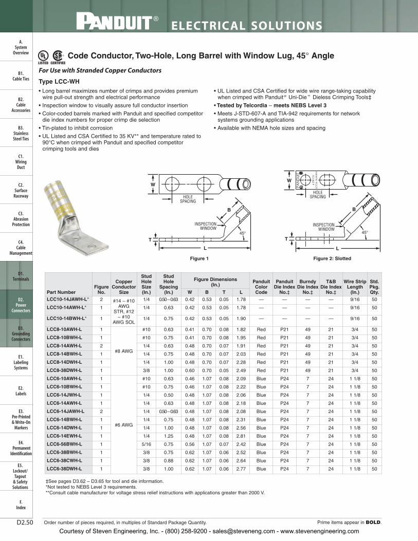
ELECTRICAL SOLUTIONS
Order number of pieces required, in multiples of Standard Package Quantity. Prime items appear in BOLD.D2.50
B2.Cable
Accessories
C1.Wiring
Duct
C3.Abrasion
Protection
C4.Cable
Management
D1.Terminals
D2.Power
Connectors
E1.LabelingSystems
E2.Labels
E3.Pre-Printed & Write-On
Markers
F.Index
B3.StainlessSteel Ties
C2.Surface
Raceway
E5.Lockout/Tagout
& SafetySolutions
B1.Cable Ties
A.System
Overview
D3.GroundingConnectors
E4.Permanent
Identification
Code Conductor, Two-Hole, Long Barrel with Window Lug, 45° Angle
• Long barrel maximizes number of crimps and provides premiumwire pull-out strength and electrical performance
• Inspection window to visually assure full conductor insertion
• Color-coded barrels marked with Panduit and specified competitordie index numbers for proper crimp die selection
• Tin-plated to inhibit corrosion
• UL Listed and CSA Certified to 35 KV** and temperature rated to90°C when crimped with Panduit and specified competitorcrimping tools and dies
• UL Listed and CSA Certified for wide wire range-taking capabilitywhen crimped with Panduit ® Uni-Die ™ Dieless Crimping Tools‡
• Tested by Telcordia – meets NEBS Level 3
• Meets J-STD-607-A and TIA-942 requirements for networksystems grounding applications
• Available with NEMA hole sizes and spacing
W
HOLESPACING
INSPECTIONWINDOW
L
B
45°
T
For Use with Stranded Copper Conductors
Type LCC-WH
‡See pages D3.62 – D3.65 for tool and die information.*Not tested to NEBS Level 3 requirements.**Consult cable manufacturer for voltage stress relief instructions with applications greater than 2000 V.
B
INSPECTIONWINDOW
W
HOLESPACING
L
45°
T
Figure 1 Figure 2: Slotted
Part NumberFigure
No.
CopperConductor
Size
StudHoleSize(In.)
StudHole
Spacing (In.)
Figure Dimensions (In.)
PanduitColorCode
Panduit Die Index
No.‡
BurndyDie Index
No.‡
T&BDie Index
No.‡
Wire Strip Length
(In.)
Std.Pkg.Qty.W B T L
LCC10-14JAWH-L* 2 #14 – #10AWG
STR, #12– #10
AWG SOL
1/4 0.50 –0.63 0.42 0.53 0.05 1.78 — — — — 9/16 50
LCC10-14AWH-L* 1 1/4 0.63 0.42 0.53 0.05 1.78 — — — — 9/16 50
LCC10-14BWH-L* 1 1/4 0.75 0.42 0.53 0.05 1.90 — — — — 9/16 50
LCC8-10AWH-L 1
#8 AWG
#10 0.63 0.41 0.70 0.08 1.82 Red P21 49 21 3/4 50
LCC8-10BWH-L 1 #10 0.75 0.41 0.70 0.08 1.95 Red P21 49 21 3/4 50
LCC8-14AWH-L 2 1/4 0.63 0.48 0.70 0.07 1.91 Red P21 49 21 3/4 50
LCC8-14BWH-L 1 1/4 0.75 0.48 0.70 0.07 2.03 Red P21 49 21 3/4 50
LCC8-14DWH-L 1 1/4 1.00 0.48 0.70 0.07 2.28 Red P21 49 21 3/4 50
LCC8-38DWH-L 1 3/8 1.00 0.60 0.70 0.05 2.49 Red P21 49 21 3/4 50
LCC6-10AWH-L 1
#6 AWG
#10 0.63 0.46 1.07 0.08 2.09 Blue P24 7 24 1 1/8 50
LCC6-10BWH-L 1 #10 0.75 0.46 1.07 0.08 2.22 Blue P24 7 24 1 1/8 50
LCC6-14JWH-L 1 1/4 0.50 0.48 1.07 0.08 2.06 Blue P24 7 24 1 1/8 50
LCC6-14AWH-L 1 1/4 0.63 0.48 1.07 0.08 2.18 Blue P24 7 24 1 1/8 50
LCC6-14JAWH-L 2 1/4 0.50 –0.63 0.48 1.07 0.08 2.08 Blue P24 7 24 1 1/8 50
LCC6-14BWH-L 1 1/4 0.75 0.48 1.07 0.08 2.31 Blue P24 7 24 1 1/8 50
LCC6-14DWH-L 1 1/4 1.00 0.48 1.07 0.08 2.56 Blue P24 7 24 1 1/8 50
LCC6-14EWH-L 1 1/4 1.25 0.48 1.07 0.08 2.81 Blue P24 7 24 1 1/8 50
LCC6-56BWH-L 1 5/16 0.75 0.56 1.07 0.07 2.42 Blue P24 7 24 1 1/8 50
LCC6-38BWH-L 1 3/8 0.75 0.62 1.07 0.06 2.52 Blue P24 7 24 1 1/8 50
LCC6-38CWH-L 1 3/8 0.88 0.62 1.07 0.06 2.64 Blue P24 7 24 1 1/8 50
LCC6-38DWH-L 1 3/8 1.00 0.62 1.07 0.06 2.77 Blue P24 7 24 1 1/8 50
Courtesy of Steven Engineering, Inc. - (800) 258-9200 - [email protected] - www.stevenengineering.com

LTBW
Std.Pkg.Qty.
Wire Strip Length
(In.)
T&BDie Index
No.‡
BurndyDie Index
No.‡
Panduit Die Index
No.‡
PanduitColorCode
Figure Dimensions (In.)
StudHole
Spacing (In.)
StudHoleSize(In.)
CopperConductor
SizeFigure
No.Part Number
For technical assistance in the U.S., call 866-405-6654 (outside the U.S., see inside back cover for directory)
ELECTRICAL SOLUTIONS
D2.51
B2.Cable
Accessories
C1.Wiring
Duct
C3.Abrasion
Protection
C4.Cable
Management
D1.Terminals
D2.Power
Connectors
E1.LabelingSystems
E2.Labels
E3.Pre-Printed & Write-On
Markers
F.Index
B3.StainlessSteel Ties
C2.Surface
Raceway
E5.Lockout/Tagout
& SafetySolutions
B1.Cable Ties
D3.GroundingConnectors
E4.Permanent
Identification
Code Conductor, Two-Hole, Long Barrel with Window Lug, 45° Angle (continued)
‡See pages D3.62 – D3.65 for tool and die information.**Consult cable manufacturer for voltage stress relief instructions with applications greater than 2000 V.◆NEMA hole sizes and spacing. Table continues on page D2.52
A.System
Overview
LCC4-10AWH-L 1
#4 – #3AWG
STR, #2AWG SOL
#10 0.63 0.55 1.05 0.09 2.11 Gray P29 8 29 1 1/8 50
LCC4-10BWH-L 1 #10 0.75 0.55 1.05 0.09 2.23 Gray P29 8 29 1 1/8 50
LCC4-14AWH-L 1 1/4 0.63 0.55 1.05 0.09 2.20 Gray P29 8 29 1 1/8 50
LCC4-14BWH-L 1 1/4 0.75 0.55 1.05 0.09 2.32 Gray P29 8 29 1 1/8 50
LCC4-38DWH-L 1 3/8 1.00 0.62 1.05 0.08 2.79 Gray P29 8 29 1 1/8 50
LCC2-10AWH-Q 1
#2 AWG
#10 0.63 0.60 1.16 0.10 2.21 Brown P33 10 33 1 1/4 25
LCC2-10BWH-Q 1 #10 0.75 0.60 1.16 0.10 2.33 Brown P33 10 33 1 1/4 25
LCC2-14AWH-Q 1 1/4 0.63 0.60 1.16 0.10 2.31 Brown P33 10 33 1 1/4 25
LCC2-14BWH-Q 1 1/4 0.75 0.60 1.16 0.10 2.43 Brown P33 10 33 1 1/4 25
LCC2-14DWH-Q 1 1/4 1.00 0.60 1.16 0.10 2.68 Brown P33 10 33 1 1/4 25
LCC2-56BWH-Q 1 5/16 0.75 0.66 1.16 0.10 2.55 Brown P33 10 33 1 1/4 25
LCC2-56CWH-Q 1 5/16 0.88 0.66 1.16 0.10 2.68 Brown P33 10 33 1 1/4 25
LCC2-38BWH-Q 1 3/8 0.75 0.66 1.16 0.10 2.63 Brown P33 10 33 1 1/4 25
LCC2-38CWH-Q 1 3/8 0.88 0.66 1.16 0.10 2.75 Brown P33 10 33 1 1/4 25
LCC2-38DWH-Q 1 3/8 1.00 0.66 1.16 0.10 2.88 Brown P33 10 33 1 1/4 25
LCC2-38WH-Q 1 3/8 1.75 0.66 1.16 0.10 3.63 Brown P33 10 33 1 1/4 25
LCC2-12WH-Q 1 1/2 1.75 0.75 1.16 0.08 4.03 Brown P33 10 33 1 1/4 25
LCC1-14AWH-E 1
#1 AWG
1/4 0.63 0.70 1.36 0.11 2.46 Green P37 11 37 1 7/16 20
LCC1-14BWH-E 1 1/4 0.75 0.70 1.36 0.11 2.58 Green P37 11 37 1 7/16 20
LCC1-56BWH-E 1 5/16 0.75 0.70 1.36 0.11 2.71 Green P37 11 37 1 7/16 20
LCC1-56CWH-E 1 5/16 0.88 0.70 1.36 0.11 2.83 Green P37 11 37 1 7/16 20
LCC1-38DWH-E 1 3/8 1.00 0.70 1.36 0.11 3.04 Green P37 11 37 1 7/16 20
LCC1-12WH-E 1 1/2 1.75 0.75 1.36 0.09 4.20 Green P37 11 37 1 7/16 20
LCC1/0-14AWH-X 1
1/0 AWG
1/4 0.63 0.76 1.44 0.12 2.61 Pink P42 12 42 1 1/2 10
LCC1/0-14BWH-X 1 1/4 0.75 0.76 1.44 0.12 2.73 Pink P42 12 42 1 1/2 10
LCC1/0-14DWH-X 1 1/4 1.00 0.76 1.44 0.12 2.98 Pink P42 12 42 1 1/2 10
LCC1/0-38DWH-X 1 3/8 1.00 0.76 1.44 0.12 3.11 Pink P42 12 42 1 1/2 10
LCC1/0-38WH-X 1 3/8 1.75 0.76 1.44 0.12 3.86 Pink P42 12 42 1 1/2 10
LCC1/0-12DWH-X 1 1/2 1.00 0.80 1.44 0.12 3.37 Pink P42 12 42 1 1/2 10
LCC1/0-12WH-X 1 1/2 1.75 0.80 1.44 0.12 4.28 Pink P42 12 42 1 1/2 10
LCC2/0-14AWH-X 1
2/0 AWG
1/4 0.63 0.85 1.50 0.13 2.76 Black P45 13 45 1 9/16 10
LCC2/0-14BWH-X 1 1/4 0.75 0.85 1.50 0.13 2.88 Black P45 13 45 1 9/16 10
LCC2/0-56DWH-X 1 5/16 1.00 0.85 1.50 0.13 3.13 Black P45 13 45 1 9/16 10
LCC2/0-38DWH-X 1 3/8 1.00 0.85 1.50 0.13 3.20 Black P45 13 45 1 9/16 10
LCC2/0-12DWH-X 1 1/2 1.00 0.85 1.50 0.13 3.45 Black P45 13 45 1 9/16 10
LCC2/0-12WH-X 1 1/2 1.75 0.85 1.50 0.13 4.36 Black P45 13 45 1 9/16 10
LCC3/0-14BWH-X 1
3/0 AWG
1/4 0.75 0.96 1.50 0.13 2.91 Orange P50 14 50 1 9/16 10
LCC3/0-56DWH-X 1 5/16 1.00 0.96 1.50 0.13 3.16 Orange P50 14 50 1 9/16 10
LCC3/0-38DWH-X 1 3/8 1.00 0.96 1.50 0.13 3.22 Orange P50 14 50 1 9/16 10
LCC3/0-12DWH-X 1 1/2 1.00 0.96 1.50 0.13 3.47 Orange P50 14 50 1 9/16 10
LCC3/0-12WH-X 1 1/2 1.75 0.96 1.50 0.13 4.38 Orange P50 14 50 1 9/16 10
LCC4/0-14AWH-X 1
4/0 AWG
1/4 0.63 1.06 1.56 0.14 2.85 Purple P54 15 54 1 5/8 10
LCC4/0-14BWH-X 1 1/4 0.75 1.06 1.56 0.14 2.98 Purple P54 15 54 1 5/8 10
LCC4/0-56DWH-X 1 5/16 1.00 1.06 1.56 0.14 3.24 Purple P54 15 54 1 5/8 10
LCC4/0-38DWH-X 1 3/8 1.00 1.06 1.56 0.14 3.31 Purple P54 15 54 1 5/8 10
LCC4/0-38WH-X 1 3/8 1.75 1.06 1.56 0.14 4.06 Purple P54 15 54 1 5/8 10
LCC4/0-12DWH-X 1 1/2 1.00 1.06 1.56 0.14 3.54 Purple P54 15 54 1 5/8 10
◆ LCC4/0-12WH-X 1 1/2 1.75 1.06 1.56 0.14 4.45 Purple P54 15 54 1 5/8 10
Courtesy of Steven Engineering, Inc. - (800) 258-9200 - [email protected] - www.stevenengineering.com

ELECTRICAL SOLUTIONS
Prime items appear in BOLD.D2.52
B2.Cable
Accessories
C1.Wiring
Duct
C3.Abrasion
Protection
C4.Cable
Management
D1.Terminals
D2.Power
Connectors
E1.LabelingSystems
E2.Labels
E3.Pre-Printed & Write-On
Markers
F.Index
B3.StainlessSteel Ties
C2.Surface
Raceway
E5.Lockout/Tagout
& SafetySolutions
B1.Cable Ties
A.System
Overview
D3.GroundingConnectors
E4.Permanent
Identification
Code Conductor, Two-Hole, Long Barrel with Window Lug, 45° Angle (continued)
‡See pages D3.62 – D3.65 for tool and die information.**Consult cable manufacturer for voltage stress relief instructions with applications greater than 2000 V.◆NEMA hole sizes and spacing.
LTBW
Std.Pkg.Qty.
Wire Strip Length
(In.)
T&BDie Index
No.‡
BurndyDie Index
No.‡
Panduit Die Index
No.‡
PanduitColorCode
Figure Dimensions (In.)
StudHole
Spacing (In.)
StudHoleSize(In.)
CopperConductor
SizeFigure
No.Part NumberLCC250-56DWH-X 1
250 kcmil
5/16 1.00 1.17 1.61 0.14 3.31 Yellow P62 16 62 1 11/16 10
LCC250-38DWH-X 1 3/8 1.00 1.17 1.61 0.14 3.38 Yellow P62 16 62 1 11/16 10
LCC250-12DWH-X 1 1/2 1.00 1.17 1.61 0.14 3.61 Yellow P62 16 62 1 11/16 10
◆ LCC250-12WH-X 1 1/2 1.75 1.17 1.61 0.14 4.52 Yellow P62 16 62 1 11/16 10
LCC300-38DWH-X 1300 kcmil
3/8 1.00 1.19 2.24 0.16 3.93 White P66 17 66 2 5/16 10
◆ LCC300-12WH-X 1 1/2 1.75 1.19 2.24 0.16 5.11 White P66 17 66 2 5/16 10
LCC350-14BWH-X 1
350 kcmil
1/4 0.75 1.28 2.24 0.17 3.48 Red P71 18 71 2 5/16 10
LCC350-38DWH-X 1 3/8 1.00 1.28 2.24 0.17 3.96 Red P71 18 71 2 5/16 10
◆ LCC350-12WH-X 1 1/2 1.75 1.28 2.24 0.17 5.14 Red P71 18 71 2 5/16 10
LCC400-14BWH-6 1
400 kcmil
1/4 0.75 1.39 2.30 0.18 3.59 Blue P76 19 76 2 3/8 6
LCC400-38DWH-6 1 3/8 1.00 1.39 2.30 0.18 4.07 Blue P76 19 76 2 3/8 6
◆ LCC400-12WH-6 1 1/2 1.75 1.28 2.30 0.17 5.24 Blue P76 19 76 2 3/8 6
LCC500-14BWH-6 1
500 kcmil
1/4 0.75 1.54 2.50 0.22 3.80 Brown P87 20 87 2 9/16 6
LCC500-38DWH-6 1 3/8 1.00 1.54 2.50 0.22 4.29 Brown P87 20 87 2 9/16 6
◆ LCC500-12WH-6 1 1/2 1.75 1.54 2.50 0.22 5.46 Brown P87 20 87 2 9/16 6
LCC600-38DWH-6 1600 kcmil
3/8 1.00 1.70 2.69 0.26 4.47 Green P94 22 94 2 3/4 6
◆ LCC600-12WH-6 1 1/2 1.75 1.70 2.69 0.26 5.65 Green P94 22 94 2 3/4 6
Courtesy of Steven Engineering, Inc. - (800) 258-9200 - [email protected] - www.stevenengineering.com

For technical assistance in the U.S., call 866-405-6654 (outside the U.S., see inside back cover for directory)
ELECTRICAL SOLUTIONS
D2.53
B2.Cable
Accessories
C1.Wiring
Duct
C3.Abrasion
Protection
C4.Cable
Management
D1.Terminals
D2.Power
Connectors
E1.LabelingSystems
E2.Labels
E3.Pre-Printed & Write-On
Markers
F.Index
B3.StainlessSteel Ties
C2.Surface
Raceway
E5.Lockout/Tagout
& SafetySolutions
B1.Cable Ties
A.System
Overview
D3.GroundingConnectors
E4.Permanent
Identification
Code Conductor, Two-Hole, Long Barrel with Window Lug, 90° Angle
• Long barrel maximizes number of crimps and provides premiumwire pull-out strength and electrical performance
• Inspection window to visually assure full conductor insertion
• Color-coded barrels marked with Panduit and specified competitordie index numbers for proper crimp die selection
• Tin-plated to inhibit corrosion
• UL Listed and CSA Certified to 35 KV** and temperature rated to 90°C when crimped with Panduit and specified competitorcrimping tools and dies
• UL Listed and CSA Certified for wide wire range-taking capabilitywhen crimped with Panduit® Uni-Die ™ Dieless Crimping Tools‡
• Tested by Telcordia – meets NEBS Level 3
• Meets J-STD-607-A and TIA-942 requirements for networksystems grounding applications
• Available with NEMA hole sizes and spacing
INSPECTIONWINDOWW
HOLESPACING
B
L
90°
T
For Use with Stranded Copper Conductors
Type LCC-WF
B
INSPECTIONWINDOW
HOLESPACING
W
L
90°
T
Figure 1 Figure 2: Slotted
‡See pages D3.62 – D3.65 for tool and die information.*Not tested to NEBS Level 3 requirements.**Consult cable manufacturer for voltage stress relief instructions with applications greater than 2000 V.
Table continues on pages D2.54 — D2.55
Part NumberFigure
No.
Copper Conductor
Size
Stud Hole Size (In.)
StudHole
Spacing (In.)
Figure Dimensions (In.)
Panduit Color Code
Panduit Die Index
No.‡
Burndy Die Index
No.‡
T&BDie Index
No.‡
Wire Strip Length
(In.)
Std.Pkg.Qty.W B T L
LCC10-14JAWF-L* 2 #14 – #10AWG
STR, #12– #10
AWG SOL
1/4 0.50 – 0.63 0.42 0.53 0.05 1.56 — — — — 9/16 50
LCC10-14AWF-L* 1 1/4 0.63 0.42 0.53 0.05 1.56 — — — — 9/16 50
LCC10-14BWF-L* 1 1/4 0.75 0.42 0.53 0.05 1.69 — — — — 9/16 50
LCC8-10AWF-L 1
#8 AWG
#10 0.63 0.41 0.70 0.08 1.53 Red P21 49 21 3/4 50
LCC8-10BWF-L 1 #10 0.75 0.41 0.70 0.08 1.65 Red P21 49 21 3/4 50
LCC8-14AWF-L 1 1/4 0.63 0.48 0.70 0.07 1.61 Red P21 49 21 3/4 50
LCC8-14BWF-L 1 1/4 0.75 0.48 0.70 0.07 1.74 Red P21 49 21 3/4 50
LCC8-14DWF-L 1 1/4 1.00 0.48 0.70 0.07 1.99 Red P21 49 21 3/4 50
LCC8-38DWF-L 1 3/8 1.00 0.60 0.70 0.05 2.21 Red P21 49 21 3/4 50
LCC6-10AWF-L 1
#6 AWG
#10 0.63 0.46 1.07 0.08 1.57 Blue P24 7 24 1 1/8 50
LCC6-10BWF-L 1 #10 0.75 0.46 1.07 0.08 1.69 Blue P24 7 24 1 1/8 50
LCC6-14JWF-L 1 1/4 0.50 0.48 1.07 0.08 1.53 Blue P24 7 24 1 1/8 50
LCC6-14AWF-L 1 1/4 0.63 0.48 1.07 0.08 1.66 Blue P24 7 24 1 1/8 50
LCC6-14JAWF-L 2 1/4 0.50 – 0.63 0.48 1.07 0.08 1.66 Blue P24 7 24 1 1/8 50
LCC6-14BWF-L 1 1/4 0.75 0.48 1.07 0.08 1.78 Blue P24 7 24 1 1/8 50
LCC6-14DWF-L 1 1/4 1.00 0.48 1.07 0.08 2.03 Blue P24 7 24 1 1/8 50
LCC6-14EWF-L 1 1/4 1.25 0.48 1.07 0.08 2.28 Blue P24 7 24 1 1/8 50
LCC6-56BWF-L 1 5/16 0.75 0.56 1.07 0.07 1.90 Blue P24 7 24 1 1/8 50
LCC6-38BWF-L 1 3/8 0.75 0.62 1.07 0.06 2.00 Blue P24 7 24 1 1/8 50
LCC6-38CWF-L 1 3/8 0.88 0.62 1.07 0.06 2.13 Blue P24 7 24 1 1/8 50
LCC6-38DWF-L 1 3/8 1.00 0.62 1.07 0.06 2.25 Blue P24 7 24 1 1/8 50
Courtesy of Steven Engineering, Inc. - (800) 258-9200 - [email protected] - www.stevenengineering.com

ELECTRICAL SOLUTIONS
Order number of pieces required, in multiples of Standard Package Quantity. Prime items appear in BOLD.D2.54
B2.Cable
Accessories
C1.Wiring
Duct
C3.Abrasion
Protection
C4.Cable
Management
D1.Terminals
D2.Power
Connectors
E1.LabelingSystems
E2.Labels
E3.Pre-Printed & Write-On
Markers
F.Index
B3.StainlessSteel Ties
C2.Surface
Raceway
E5.Lockout/Tagout
& SafetySolutions
B1.Cable Ties
A.System
Overview
D3.GroundingConnectors
E4.Permanent
Identification
Code Conductor, Two-Hole, Long Barrel with Window Lug, 90° Angle (continued)
‡See pages D3.62 – D3.65 for tool and die information.**Consult cable manufacturer for voltage stress relief instructions with applications greater than 2000 V.◆NEMA hole sizes and spacing.
LTBW
Std.Pkg.Qty.
Wire Strip Length
(In.)
T&BDie Index
No.‡
Burndy Die Index
No.‡
Panduit Die Index
No.‡
Panduit Color Code
Figure Dimensions (In.)
StudHole
Spacing (In.)
Stud Hole Size (In.)
Copper Conductor
SizeFigure
No.Part NumberLCC4-10AWF-L 1
#4 – #3AWG
STR, #2AWG SOL
#10 0.63 0.55 1.05 0.09 1.65 Gray P29 8 29 1 1/8 50
LCC4-10BWF-L 1 #10 0.75 0.55 1.05 0.09 1.78 Gray P29 8 29 1 1/8 50
LCC4-14AWF-L 1 1/4 0.63 0.55 1.05 0.09 1.74 Gray P29 8 29 1 1/8 50
LCC4-14BWF-L 1 1/4 0.75 0.55 1.05 0.09 1.87 Gray P29 8 29 1 1/8 50
LCC4-38DWF-L 1 3/8 1.00 0.62 1.05 0.08 2.34 Gray P29 8 29 1 1/8 50
LCC2-10AWF-Q 1
#2 AWG
#10 0.63 0.60 1.16 0.10 1.76 Brown P33 10 33 1 1/4 25
LCC2-10BWF-Q 1 #10 0.75 0.60 1.16 0.10 1.89 Brown P33 10 33 1 1/4 25
LCC2-14AWF-Q 1 1/4 0.63 0.60 1.16 0.10 1.86 Brown P33 10 33 1 1/4 25
LCC2-14BWF-Q 1 1/4 0.75 0.60 1.16 0.10 1.99 Brown P33 10 33 1 1/4 25
LCC2-14DWF-Q 1 1/4 1.00 0.60 1.16 0.10 2.24 Brown P33 10 33 1 1/4 25
LCC2-56BWF-Q 1 5/16 0.75 0.66 1.16 0.10 2.11 Brown P33 10 33 1 1/4 25
LCC2-56CWF-Q 1 5/16 0.88 0.66 1.16 0.10 2.24 Brown P33 10 33 1 1/4 25
LCC2-38BWF-Q 1 3/8 0.75 0.66 1.16 0.10 2.19 Brown P33 10 33 1 1/4 25
LCC2-38CWF-Q 1 3/8 0.88 0.66 1.16 0.10 2.31 Brown P33 10 33 1 1/4 25
LCC2-38DWF-Q 1 3/8 1.00 0.66 1.16 0.10 2.44 Brown P33 10 33 1 1/4 25
LCC2-38WF-Q 1 3/8 1.75 0.66 1.16 0.10 3.19 Brown P33 10 33 1 1/4 25
LCC2-12WF-Q 1 1/2 1.75 0.75 1.16 0.08 3.61 Brown P33 10 33 1 1/4 25
LCC1-14AWF-E 1
#1 AWG
1/4 0.63 0.70 1.36 0.11 1.94 Green P37 11 37 1 7/16 20
LCC1-14BWF-E 1 1/4 0.75 0.70 1.36 0.11 2.06 Green P37 11 37 1 7/16 20
LCC1-56BWF-E 1 5/16 0.75 0.70 1.36 0.11 2.19 Green P37 11 37 1 7/16 20
LCC1-56CWF-E 1 5/16 0.88 0.70 1.36 0.11 2.31 Green P37 11 37 1 7/16 20
LCC1-38DWF-E 1 3/8 1.00 0.70 1.36 0.11 2.51 Green P37 11 37 1 7/16 20
LCC1-12WF-E 1 1/2 1.75 0.75 1.36 0.09 3.68 Green P37 11 37 1 7/16 20
LCC1/0-14AWF-X 1
1/0 AWG
1/4 0.63 0.76 1.44 0.12 2.08 Pink P42 12 42 1 1/2 10
LCC1/0-14BWF-X 1 1/4 0.75 0.76 1.44 0.12 2.20 Pink P42 12 42 1 1/2 10
LCC1/0-14DWF-X 1 1/4 1.00 0.76 1.44 0.12 2.45 Pink P42 12 42 1 1/2 10
LCC1/0-38DWF-X 1 3/8 1.00 0.76 1.44 0.12 2.58 Pink P42 12 42 1 1/2 10
LCC1/0-38WF-X 1 3/8 1.75 0.76 1.44 0.12 3.33 Pink P42 12 42 1 1/2 10
LCC1/0-12DWF-X 1 1/2 1.00 0.80 1.44 0.12 2.85 Pink P42 12 42 1 1/2 10
LCC1/0-12WF-X 1 1/2 1.75 0.80 1.44 0.12 3.75 Pink P42 12 42 1 1/2 10
LCC2/0-14AWF-X 1
2/0 AWG
1/4 0.63 0.85 1.50 0.13 2.22 Black P45 13 45 1 9/16 10
LCC2/0-14BWF-X 1 1/4 0.75 0.85 1.50 0.13 2.34 Black P45 13 45 1 9/16 10
LCC2/0-56DWF-X 1 5/16 1.00 0.85 1.50 0.13 2.59 Black P45 13 45 1 9/16 10
LCC2/0-38DWF-X 1 3/8 1.00 0.85 1.50 0.13 2.66 Black P45 13 45 1 9/16 10
LCC2/0-12DWF-X 1 1/2 1.00 0.85 1.50 0.13 2.91 Black P45 13 45 1 9/16 10
LCC2/0-12WF-X 1 1/2 1.75 0.85 1.50 0.13 3.82 Black P45 13 45 1 9/16 10
LCC3/0-14BWF-X 1
3/0 AWG
1/4 0.75 0.96 1.50 0.13 2.42 Orange P50 14 50 1 9/16 10
LCC3/0-56DWF-X 1 5/16 1.00 0.96 1.50 0.13 2.67 Orange P50 14 50 1 9/16 10
LCC3/0-38DWF-X 1 3/8 1.00 0.96 1.50 0.13 2.73 Orange P50 14 50 1 9/16 10
LCC3/0-12DWF-X 1 1/2 1.00 0.96 1.50 0.13 2.98 Orange P50 14 50 1 9/16 10
LCC3/0-12WF-X 1 1/2 1.75 0.96 1.50 0.13 3.89 Orange P50 14 50 1 9/16 10
LCC4/0-14AWF-X 1
4/0 AWG
1/4 0.63 1.06 1.56 0.14 2.38 Purple P54 15 54 1 5/8 10
LCC4/0-14BWF-X 1 1/4 0.75 1.06 1.56 0.14 2.50 Purple P54 15 54 1 5/8 10
LCC4/0-56DWF-X 1 5/16 1.00 1.06 1.56 0.14 2.77 Purple P54 15 54 1 5/8 10
LCC4/0-38DWF-X 1 3/8 1.00 1.06 1.56 0.14 2.84 Purple P54 15 54 1 5/8 10
LCC4/0-38WF-X 1 3/8 1.75 1.06 1.56 0.14 3.59 Purple P54 15 54 1 5/8 10
LCC4/0-12DWF-X 1 1/2 1.00 1.06 1.56 0.14 3.07 Purple P54 15 54 1 5/8 10
◆ LCC4/0-12WF-X 1 1/2 1.75 1.06 1.56 0.14 3.98 Purple P54 15 54 1 5/8 10
Courtesy of Steven Engineering, Inc. - (800) 258-9200 - [email protected] - www.stevenengineering.com

LTBW
Std.Pkg.Qty.
Wire Strip Length
(In.)
T&BDie Index
No.‡
Burndy Die Index
No.‡
Panduit Die Index
No.‡
Panduit Color Code
Figure Dimensions (In.)
StudHole
Spacing (In.)
Stud Hole Size (In.)
Copper Conductor
SizeFigure
No.Part Number
For technical assistance in the U.S., call 866-405-6654 (outside the U.S., see inside back cover for directory)
ELECTRICAL SOLUTIONS
D2.55
B2.Cable
Accessories
C1.Wiring
Duct
C3.Abrasion
Protection
C4.Cable
Management
D1.Terminals
D2.Power
Connectors
E1.LabelingSystems
E2.Labels
E3.Pre-Printed & Write-On
Markers
F.Index
B3.StainlessSteel Ties
C2.Surface
Raceway
E5.Lockout/Tagout
& SafetySolutions
B1.Cable Ties
A.System
Overview
D3.GroundingConnectors
E4.Permanent
Identification
Code Conductor, Two-Hole, Long Barrel with Window, Narrow Tongue Lug
Code Conductor, Two-Hole, Long Barrel with Window Lug, 90° Angle (continued)
‡See pages D3.62 – D3.65 for tool and die information.**Consult cable manufacturer for voltage stress relief instructions with applications greater than 2000 V.◆NEMA hole sizes and spacing.
• Narrow tongue width for limited space applications
• Long barrel maximizes number of crimps and provides premiumwire pull-out strength and electrical performance
• Inspection window to visually assure full conductor insertion
• Color-coded barrels marked with Panduit and specified competitordie index numbers for proper crimp die selection
• Tin-plated to inhibit corrosion
• UL Listed and CSA Certified to 35 KV** and temperature rated to 90°C when crimped with Panduit and specified competitorcrimping tools and dies
• UL Listed and CSA Certified for wide wire range-taking capabilitywhen crimped with Panduit® Uni-Die ™ Dieless Crimping Tools‡
• Tested by Telcordia – meets NEBS Level 3
• Meets J-STD-607-A and TIA-942 requirements for networksystems grounding applications
• Available with NEMA hole sizes and spacing
For Use with Stranded Copper Conductors
Type LCCN-W
HOLESPACING
L
W
INSPECTIONWINDOW
B
T
‡See pages D3.62 – D3.65 for tool and die information.**Consult cable manufacturer for voltage stress relief instructions with applications greater than 2000 V.◆NEMA hole sizes and spacing.
Part Number
CopperConductor
Size
StudHole
Size (In.)
StudHole
Spacing(In.)
Figure Dimensions (In.) Panduit
Color Code
PanduitDie Index
No.‡
Burndy Die Index
No.‡
T&B Die Index
No.‡
Wire StripLength
(In.)
Std.Pkg.Qty.W B T L
LCCN750-38DW-6 750 kcmil 3/8 1.00 1.30 2.88 0.28 5.72 Black P106 24 106 2 15/16 6
◆ LCCN750-12W-6 750 kcmil 1/2 1.75 1.30 2.88 0.28 6.66 Black P106 24 106 2 15/16 6
LCC250-56DWF-X 1
250 kcmil
5/16 1.00 1.17 1.61 0.14 2.83 Yellow P62 16 62 1 11/16 10
LCC250-38DWF-X 1 3/8 1.00 1.17 1.61 0.14 2.90 Yellow P62 16 62 1 11/16 10
LCC250-12DWF-X 1 1/2 1.00 1.17 1.61 0.14 3.13 Yellow P62 16 62 1 11/16 10
◆ LCC250-12WF-X 1 1/2 1.75 1.17 1.61 0.14 4.04 Yellow P62 16 62 1 11/16 10
LCC300-38DWF-X 1300 kcmil
3/8 1.00 1.19 2.24 0.16 2.88 White P66 17 66 2 5/16 10
◆ LCC300-12WF-X 1 1/2 1.75 1.19 2.24 0.16 4.06 White P66 17 66 2 5/16 10
LCC350-14BWF-X 1
350 kcmil
1/4 0.75 1.28 2.24 0.17 2.46 Red P71 18 71 2 5/16 10
LCC350-38DWF-X 1 3/8 1.00 1.28 2.24 0.17 2.94 Red P71 18 71 2 5/16 10
◆ LCC350-12WF-X 1 1/2 1.75 1.28 2.24 0.17 4.12 Red P71 18 71 2 5/16 10
LCC400-14BWF-6 1
400 kcmil
1/4 0.75 1.39 2.30 0.18 2.54 Blue P76 19 76 2 3/8 6
LCC400-38DWF-6 1 3/8 1.00 1.39 2.30 0.18 3.02 Blue P76 19 76 2 3/8 6
◆ LCC400-12WF-6 1 1/2 1.75 1.39 2.30 0.18 4.20 Blue P76 19 76 2 3/8 6
LCC500-14BWF-6 1
500 kcmil
1/4 0.75 1.54 2.50 0.22 2.65 Brown P87 20 87 2 9/16 6
LCC500-38DWF-6 1 3/8 1.00 1.54 2.50 0.22 3.13 Brown P87 20 87 2 9/16 6
◆ LCC500-12WF-6 1 1/2 1.75 1.54 2.50 0.22 4.31 Brown P87 20 87 2 9/16 6
LCC600-38DWF-6 1600 kcmil
3/8 1.00 1.70 2.69 0.26 3.26 Green P94 22 94 2 3/4 6
◆ LCC600-12WF-6 1 1/2 1.75 1.70 2.69 0.26 4.44 Green P94 22 94 2 3/4 6
Courtesy of Steven Engineering, Inc. - (800) 258-9200 - [email protected] - www.stevenengineering.com

ELECTRICAL SOLUTIONS
Prime items appear in BOLD.D2.56
B2.Cable
Accessories
C1.Wiring
Duct
C3.Abrasion
Protection
C4.Cable
Management
D1.Terminals
D2.Power
Connectors
E1.LabelingSystems
E2.Labels
E3.Pre-Printed & Write-On
Markers
F.Index
B3.StainlessSteel Ties
C2.Surface
Raceway
E5.Lockout/Tagout
& SafetySolutions
B1.Cable Ties
A.System
Overview
D3.GroundingConnectors
E4.Permanent
Identification
Code Conductor, Two-Hole, Long Barrel with Corona Relief Taper Lug
• Externally chamfered barrel end inhibits Corona effect when usedin high voltage applications
• Long barrel maximizes number of crimps and provides premiumwire pull-out strength and electrical performance
• Color-coded barrels marked with Panduit and specified competitordie index numbers for proper crimp die selection
• Enclosed barrel prevents corrosive material from entering barrelwhen used in harsh environments
• Tin-plated to inhibit corrosion
• UL Listed and CSA Certified to 35 KV** and temperature rated to 90°C when crimped with Panduit and specified competitorcrimping tools and dies
• Available with NEMA hole sizes and spacing
CORONARELIEFTAPER
W
HOLESPACING
L
T
B
To Facilitate Use with Stranded Copper Conductors in Applications of 5000 V or More
Type LCCH
‡See pages D3.66, D3.67 for tool and die information.**Consult cable manufacturer for voltage stress relief instructions with applications greater than 2000 V.◆NEMA hole sizes and spacing.
Corona Relief Taper
Part Number
Copper Conductor
Size
Stud Hole Size(In.)
Stud Hole
Spacing (In.)
Figure Dimensions(In.)
Panduit Color Code
Panduit Die Index
No.‡
Burndy Die Index
No.‡
T&B Die Index
No.‡
Wire Strip Length
(In.)
Std.Pkg.Qty.W B T L
LCCH1/0-12-X 1/0 AWG 1/2 1.75 0.80 1.44 0.12 4.86 Pink P42 12 42 1 1/2 10
LCCH2/0-12-X 2/0 AWG 1/2 1.75 0.85 1.50 0.13 4.98 Black P45 13 45 1 9/16 10
LCCH3/0-12-X 3/0 AWG 1/2 1.75 0.96 1.50 0.13 5.03 Orange P50 14 50 1 9/16 10
◆ LCCH4/0-12-X 4/0 AWG 1/2 1.75 1.06 1.56 0.14 5.13 Purple P54 15 54 1 5/8 10
◆ LCCH250-12-X 250 kcmil 1/2 1.75 1.17 1.61 0.14 5.23 Yellow P62 16 62 1 1/16 10
◆ LCCH300-12-X 300 kcmil 1/2 1.75 1.19 2.24 0.16 5.94 White P66 17 66 2 5/16 10
◆ LCCH350-12-X 350 kcmil 1/2 1.75 1.28 2.24 0.17 5.99 Red P71 18 71 2 5/16 10
◆ LCCH400-12-6 400 kcmil 1/2 1.75 1.39 2.30 0.18 6.10 Blue P76 19 76 2 3/8 6
◆ LCCH500-12-6 500 kcmil 1/2 1.75 1.54 2.50 0.22 6.36 Brown P87 20 87 2 9/16 6
◆ LCCH600-12-6 600 kcmil 1/2 1.75 1.70 2.69 0.26 6.63 Green P94 22 94 2 3/4 6
◆ LCCH750-12-6 750 kcmil 1/2 1.75 1.89 2.88 0.26 7.04 Black P106 24 106 2 15/16 6
◆ LCCH1000-12-3 1000 kcmil 1/2 1.75 2.17 3.00 0.32 7.29 White P125 27 125 3 1/16 3
Courtesy of Steven Engineering, Inc. - (800) 258-9200 - [email protected] - www.stevenengineering.com

For technical assistance in the U.S., call 866-405-6654 (outside the U.S., see inside back cover for directory)
ELECTRICAL SOLUTIONS
D2.57
B2.Cable
Accessories
C1.Wiring
Duct
C3.Abrasion
Protection
C4.Cable
Management
D1.Terminals
D2.Power
Connectors
E1.LabelingSystems
E2.Labels
E3.Pre-Printed & Write-On
Markers
F.Index
B3.StainlessSteel Ties
C2.Surface
Raceway
E5.Lockout/Tagout
& SafetySolutions
B1.Cable Ties
A.System
Overview
D3.GroundingConnectors
E4.Permanent
Identification
Code Conductor, Blank Tongue, Long Barrel Lug
• Long barrel maximizes number of crimps and provides premiumwire pull-out strength and electrical performance
• Color-coded barrels marked with Panduit and specified competitordie index numbers for proper crimp die selection
• Enclosed barrel prevents corrosive material from entering barrelwhen used in harsh environments
• Tin-plated to inhibit corrosion
• UL Recognized and CSA Certified to 35 KV** and temperaturerated to 90°C when crimped with Panduit and specified competitorcrimping tools and dies
W
L
T
B
For Use with Stranded Copper Conductors
Type LCC-00
L
W
T
B
Figure 1 Figure 2: Two-Piece Brazed TongueConstruction
‡See pages D3.62 – D3.65 for tool and die information.**Consult cable manufacturer for voltage stress relief instructions with applications greater than 2000 V.
Part NumberFigure
No.Copper
Conductor Size
Figure Dimensions (In.)
PanduitColor Code
Panduit Die Index
No.
BurndyDie Index
No.‡
T&BDie Index
No.‡
Wire StripLength
(In.)
Std.Pkg.Qty.W B T L
LCC8-00-L 1 #8 AWG 0.60 0.70 0.05 2.75 Red P21 49 21 3/4 50
LCC6-00-L 2 #6 AWG 0.75 1.13 0.16 5.00 Blue P24 7 24 1 1/8 50
LCC4-00-L 2 #4 – #3 AWGSTR, #2 AWG
SOL
0.75 1.13 0.16 5.06 Gray P29 8 29 1 1/8 50
LCC2-00-Q 1 #2 AWG 0.75 1.16 0.08 4.51 Brown P33 10 33 1 1/4 25
LCC1-00-E 1 #1 AWG 0.75 1.36 0.09 4.74 Green P37 11 37 1 7/16 20
LCC1/0-00-X 1 1/0 AWG 0.80 1.44 0.12 4.86 Pink P42 12 42 1 1/2 10
LCC2/0-00-X 1 2/0 AWG 0.85 1.50 0.13 4.98 Black P45 13 45 1 9/16 10
LCC3/0-00-X 1 3/0 AWG 0.96 1.50 0.13 5.03 Orange P50 14 50 1 9/16 10
LCC4/0-00-X 1 4/0 AWG 1.06 1.56 0.14 5.13 Purple P54 15 54 1 5/8 10
LCC250-00-X 1 250 kcmil 1.17 1.60 0.14 5.23 Yellow P62 16 62 1 11/16 10
LCC300-00-X 1 300 kcmil 1.19 2.23 0.16 5.94 White P66 17 66 2 5/16 10
LCC350-00-X 1 350 kcmil 1.28 2.23 0.17 5.99 Red P71 18 71 2 5/16 10
LCC400-00-6 1 400 kcmil 1.39 2.29 0.18 6.10 Blue P76 19 76 2 3/8 6
LCC500-00-6 1 500 kcmil 1.54 2.49 0.22 6.36 Brown P87 20 87 2 9/16 6
LCC600-00-6 1 600 kcmil 1.70 2.68 0.26 6.63 Green P94 22 94 2 3/4 6
LCC750-00-6 1 750 kcmil 1.89 2.87 0.26 7.04 Black P106 24 106 2 15/16 6
LCC1000-00-3 1 1000 kcmil 2.17 2.99 0.32 7.29 White P125 27 125 3 1/16 3
Courtesy of Steven Engineering, Inc. - (800) 258-9200 - [email protected] - www.stevenengineering.com

ELECTRICAL SOLUTIONS
Prime items appear in BOLD.D2.58
B2.Cable
Accessories
C1.Wiring
Duct
C3.Abrasion
Protection
C4.Cable
Management
D1.Terminals
D2.Power
Connectors
E1.LabelingSystems
E2.Labels
E3.Pre-Printed & Write-On
Markers
F.Index
B3.StainlessSteel Ties
C2.Surface
Raceway
E5.Lockout/Tagout
& SafetySolutions
B1.Cable Ties
A.System
Overview
D3.GroundingConnectors
E4.Permanent
Identification
Code Conductor, Blank Tongue, Long Barrel with Window Lug
• Long barrel maximizes number of crimps and provides premium wire pull-out strength and electrical performance
• Inspection window to visually assure full conductor insertion
• Color-coded barrels marked with Panduit and specified competitordie index numbers for proper crimp die selection
• Enclosed barrel prevents corrosive material from entering barrel when used in harsh environments
• Tin-plated to inhibit corrosion
• UL Recognized and CSA Certified to 35 KV** and temperaturerated to 90°C when crimped with Panduit and specified competitorcrimping tools and dies
L
W
BINSPECTION
WINDOW
T
For Use with Stranded Copper ConductorsType LCC-00W
‡See pages D3.62 – D3.65 for tool and die information.**Consult cable manufacturer for voltage stress relief instructions with applications greater than 2000 V.
Part Number
CopperConductor
Size
Figure Dimensions (In.) Panduit
ColorCode
PanduitDie Index
No.‡
BurndyDie Index
No.‡
T&BDie Index
No.‡
Wire StripLength
(In.)
Std.Pkg.Qty.W B T L
LCC8-00W-L #8 AWG 0.60 0.70 0.05 2.70 Red P21 49 21 3/4 50
LCC6-00W-L #6 AWG 0.62 1.07 0.06 3.08 Blue P24 7 24 1 1/8 50
LCC4-00W-L #4 AWG 0.62 1.05 0.08 3.09 Gray P29 8 29 1 1/8 50
LCC2-00W-Q #2 AWG 0.75 1.16 0.08 4.41 Brown P33 10 33 1 1/4 25
LCC1-00W-E #1 AWG 0.75 1.36 0.09 4.63 Green P37 11 37 1 7/16 20
LCC1/0-00W-X 1/0 AWG 0.80 1.44 0.12 4.74 Pink P42 12 42 1 1/2 10
LCC2/0-00W-X 2/0 AWG 0.85 1.50 0.13 4.83 Black P45 13 45 1 9/16 10
LCC3/0-00W-X 3/0 AWG 0.96 1.50 0.13 4.87 Orange P50 14 50 1 9/16 10
LCC4/0-00W-X 4/0 AWG 1.06 1.56 0.14 4.95 Purple P54 15 54 1 5/8 10
LCC250-00W-X 250 kcmil 1.17 1.61 0.14 5.04 Yellow P62 16 62 1 11/16 10
LCC300-00W-X 300 kcmil 1.19 2.24 0.16 5.73 White P66 17 66 2 5/16 10
LCC350-00W-X 350 kcmil 1.28 2.24 0.17 5.77 Red P71 18 71 2 5/16 10
LCC400-00W-6 400 kcmil 1.28 2.30 0.17 5.85 Blue P76 19 76 2 3/8 6
LCC500-00W-6 500 kcmil 1.54 2.50 0.22 6.13 Brown P87 20 87 2 9/16 6
LCC600-00W-6 600 kcmil 1.70 2.69 0.26 6.37 Green P94 22 94 2 3/4 6
Courtesy of Steven Engineering, Inc. - (800) 258-9200 - [email protected] - www.stevenengineering.com

For technical assistance in the U.S., call 866-405-6654 (outside the U.S., see inside back cover for directory)
ELECTRICAL SOLUTIONS
D2.59
B2.Cable
Accessories
C1.Wiring
Duct
C3.Abrasion
Protection
C4.Cable
Management
D1.Terminals
D2.Power
Connectors
E1.LabelingSystems
E2.Labels
E3.Pre-Printed & Write-On
Markers
F.Index
B3.StainlessSteel Ties
C2.Surface
Raceway
E5.Lockout/Tagout
& SafetySolutions
B1.Cable Ties
A.System
Overview
D3.GroundingConnectors
E4.Permanent
Identification
Code Conductor, Short Barrel, Butt Splice
• Short barrel for limited space applications
• Color-coded barrels marked with Panduit and specified competitordie index numbers for proper crimp die selection
• Internal wire stops to prevent over-insertion of conductor
• Tin-plated to inhibit corrosion
• UL Listed and CSA Certified to 35 KV** and temperature rated to 90°C when crimped with Panduit and specified competitorcrimping tools and dies
• Tested by Telcordia – meets NEBS Level 3
O.D.
L
For Use with Stranded Copper Conductors
Type SCSS
‡See pages D3.56, D3.57 for tool and die information.**Consult cable manufacturer for voltage stress relief instructions with applications greater than 2000 V.
Part Number Copper Conductor Size
Figure Dimensions (In.) Panduit
ColorCode
PanduitDie Index
No.‡
BurndyDie Index
No.‡
T&BDie Index
No.‡
Wire StripLength
(In.)
Std.Pkg.Qty.Barrel O.D. L
SCSS8-L #8 AWG 0.27 1.00 Red P21 49 21 7/16 50
SCSS6-L #6 AWG 0.31 1.00 Blue P24 7 24 7/16 50
SCSS4-L #4 AWG 0.38 1.00 Gray P29 8 29 7/16 50
SCSS2-Q #2 AWG 0.42 1.25 Brown P33 10 33 9/16 25
SCSS1-Q #1 AWG 0.46 1.44 Green P37 11 37 11/16 25
SCSS1/0-X 1/0 AWG 0.52 1.44 Pink P42 12 42 11/16 10
SCSS2/0-X 2/0 AWG 0.58 1.56 Black P45 13 45 3/4 10
SCSS3/0-X 3/0 AWG 0.64 1.69 Orange P50 14 50 3/4 10
SCSS4/0-X 4/0 AWG 0.71 1.81 Purple P54 15 54 13/16 10
SCSS250-X 250 kcmil 0.77 2.19 Yellow P62 16 62 1 1/16 10
Courtesy of Steven Engineering, Inc. - (800) 258-9200 - [email protected] - www.stevenengineering.com

ELECTRICAL SOLUTIONS
Prime items appear in BOLD.D2.60
B2.Cable
Accessories
C1.Wiring
Duct
C3.Abrasion
Protection
C4.Cable
Management
D1.Terminals
D2.Power
Connectors
E1.LabelingSystems
E2.Labels
E3.Pre-Printed & Write-On
Markers
F.Index
B3.StainlessSteel Ties
C2.Surface
Raceway
E5.Lockout/Tagout
& SafetySolutions
B1.Cable Ties
A.System
Overview
D3.GroundingConnectors
E4.Permanent
Identification
Code Conductor, Standard Barrel, Butt Splice
• Color-coded barrels marked with Panduit and specified competitordie index numbers for proper crimp die selection
• Internal wire stops to prevent over-insertion of conductor
• Tin-plated to inhibit corrosion
• UL Listed and CSA Certified to 35 KV** and temperature rated to 90°C when crimped with Panduit and specified competitorcrimping tools and dies
• UL Listed and CSA Certified for wide wire range-taking capabilitywhen crimped with Panduit® Uni-Die ™ Dieless Crimping Tools‡
• Tested by Telcordia – meets NEBS Level 3
• American Bureau of Shipping approved
For Use with Stranded Copper Conductors
Type SCS
O.D.
L
‡See pages D3.58 – D3.61 for tool and die information.**Consult cable manufacturer for voltage stress relief instructions with applications greater than 2000 V.
Part NumberCopper Conductor
Size
Figure Dimensions (In.) Panduit
ColorCode
PanduitDie Index
No.‡
BurndyDie Index
No.‡
T&BDie Index
No.‡
Wire StripLength
(In.)
Std.Pkg.Qty.Barrel O.D. L
SCS8-L #8 AWG 0.27 1.50 Red P21 49 21 11/16 50
SCS6-L #6 AWG 0.31 1.75 Blue P24 7 24 13/16 50
SCS4-L #4 – #3 AWG STR, #2 AWG SOL
0.38 1.75 Gray P29 8 29 13/16 50
SCS2-Q #2 AWG 0.42 1.87 Brown P33 10 33 7/8 25
SCS1-E #1 AWG 0.47 1.87 Green P37 11 37 7/8 20
SCS1/0-X 1/0 AWG 0.52 1.87 Pink P42 12 42 7/8 10
SCS2/0-X 2/0 AWG 0.58 2.00 Black P45 13 45 15/16 10
SCS3/0-X 3/0 AWG 0.64 2.12 Orange P50 14 50 1 10
SCS4/0-X 4/0 AWG 0.71 2.12 Purple P54 15 54 1 10
SCS250-X 250 kcmil 0.77 2.25 Yellow P62 16 62 1 1/16 10
SCS300-X 300 kcmil 0.81 2.25 White P66 17 66 1 1/16 10
SCS350-X 350 kcmil 0.87 2.37 Red P71 18 71 1 1/8 10
SCS400-6 400 kcmil 0.95 2.50 Blue P76 19 76 1 3/16 6
SCS500-6 500 kcmil 1.05 2.87 Brown P87 20 87 1 3/8 6
SCS600-6 600 kcmil 1.18 2.87 Green P94 22 94 1 3/8 6
SCS750-6 750 kcmil 1.29 3.37 Black P106 24 106 1 5/8 6
SCS1000-3 1000 kcmil 1.50 3.87 White P125 27 125 1 7/8 3
Courtesy of Steven Engineering, Inc. - (800) 258-9200 - [email protected] - www.stevenengineering.com

For technical assistance in the U.S., call 866-405-6654 (outside the U.S., see inside back cover for directory)
ELECTRICAL SOLUTIONS
D2.61
B2.Cable
Accessories
C1.Wiring
Duct
C3.Abrasion
Protection
C4.Cable
Management
D1.Terminals
D2.Power
Connectors
E1.LabelingSystems
E2.Labels
E3.Pre-Printed & Write-On
Markers
F.Index
B3.StainlessSteel Ties
C2.Surface
Raceway
E5.Lockout/Tagout
& SafetySolutions
B1.Cable Ties
A.System
Overview
D3.GroundingConnectors
E4.Permanent
Identification
Code Conductor, Long Barrel, Butt Splice
• Long barrel maximizes the number of crimps and providespremium wire pull-out strength and electrical performance
• Color-coded barrels marked with Panduit and specified competitordie index numbers for proper crimp die selection
• Internal wire stops to prevent over-insertion of conductor
• Tin-plated to inhibit corrosion
• UL Listed and CSA Certified to 35 KV** and temperature rated to 90°C when crimped with Panduit and specified competitorcrimping tools and dies
• UL Listed and CSA Certified for wide wire range-taking capabilitywhen crimped with Panduit® Uni-Die ™ Dieless Crimping Tools‡
• Tested by Telcordia – meets NEBS Level 3
For Use with Stranded Copper Conductors
Type SCL
O.D.
L
‡See pages D3.62 – D3.65 for tool and die information.**Consult cable manufacturer for voltage stress relief instructions with applications greater than 2000 V.
Part NumberCopper
Conductor Size
Figure Dimensions (In.) Panduit
ColorCode
Panduit Die Index
No.‡
BurndyDie Index
No.‡
T&BDie Index
No.‡
Wire Strip Length
(In.)
Std.Pkg.Qty.Barrel O.D. L
SCL8-L #8 AWG 0.27 2.25 Red P21 49 21 1 1/16 50
SCL6-L #6 AWG 0.31 2.38 Blue P24 7 24 1 1/8 50
SCL4-L #4 – #3 AWG STR, #2 AWG SOL
0.38 2.38 Gray P29 8 29 1 1/8 50
SCL2-Q #2 AWG 0.42 2.62 Brown P33 10 33 1 1/4 25
SCL1-E #1 AWG 0.47 2.87 Green P37 11 37 1 3/8 20
SCL1/0-X 1/0 AWG 0.52 2.87 Pink P42 12 42 1 3/8 10
SCL2/0-X 2/0 AWG 0.58 3.13 Black P45 13 45 1 1/2 10
SCL3/0-X 3/0 AWG 0.64 3.12 Orange P50 14 54 1 1/2 10
SCL4/0-X 4/0 AWG 0.71 3.37 Purple P54 15 54 1 5/8 10
SCL250-X 250 kcmil 0.77 3.38 Yellow P62 16 62 1 5/8 10
SCL300-X 300 kcmil 0.81 4.12 White P66 17 66 2 10
SCL350-X 350 kcmil 0.88 4.12 Red P71 18 71 2 10
SCL400-6 400 kcmil 0.95 4.37 Blue P76 19 76 2 1/8 6
SCL500-6 500 kcmil 1.06 4.62 Brown P87 20 87 2 1/4 6
SCL600-6 600 kcmil 1.19 5.50 Green P94 22 94 2 11/16 6
SCL750-6 750 kcmil 1.30 5.87 Black P106 24 106 2 7/8 6
SCL1000-3 1000 kcmil 1.50 6.12 White P125 27 125 3 3
Courtesy of Steven Engineering, Inc. - (800) 258-9200 - [email protected] - www.stevenengineering.com

ELECTRICAL SOLUTIONS
Prime items appear in BOLD.D2.62
B2.Cable
Accessories
C1.Wiring
Duct
C3.Abrasion
Protection
C4.Cable
Management
D1.Terminals
D2.Power
Connectors
E1.LabelingSystems
E2.Labels
E3.Pre-Printed & Write-On
Markers
F.Index
B3.StainlessSteel Ties
C2.Surface
Raceway
E5.Lockout/Tagout
& SafetySolutions
B1.Cable Ties
A.System
Overview
D3.GroundingConnectors
E4.Permanent
Identification
Code Conductor, Long Barrel with Corona Relief Taper Splice
• Externally chamfered barrel end inhibits Corona effect when used in high voltage applications
• Color-coded barrels marked with Panduit and specified competitordie index numbers for proper crimp die selection
• Internal wire stops to prevent over-insertion of conductor
• Tin-plated to inhibit corrosion
• UL Listed and CSA Certified to 35 KV** and temperature rated to 90°C when crimped with Panduit and specified competitorcrimping tools and dies
To Facilitate Use with Stranded Copper Conductors in Applications of 5000 V or More
Type SCH
O.D.
L
‡See pages D3.66, D3.67 for tool and die information.**Consult cable manufacturer for voltage stress relief instructions with applications greater than 2000 V.
Part NumberCopper Conductor
Size
Figure Dimensions (In.) Panduit
ColorCode
PanduitDie Index
No.‡
BurndyDie Index
No.‡
T&BDie Index
No.‡
Wire StripLength
(In.)
Std.Pkg.Qty.Barrel O.D. L
SCH6-L #6 AWG 0.31 1.97 Blue P24 7 24 15/16 50
SCH4-L #4 AWG 0.38 1.97 Gray P29 8 29 15/16 50
SCH2-Q #2 AWG 0.42 2.13 Brown P33 10 33 1 25
SCH1-E #1 AWG 0.47 2.13 Green P37 11 37 1 20
SCH1/0-X 1/0 AWG 0.52 2.13 Pink P42 12 42 1 10
SCH2/0-X 2/0 AWG 0.58 2.28 Black P45 13 45 1 1/16 10
SCH3/0-X 3/0 AWG 0.64 2.47 Orange P50 14 50 1 3/16 10
SCH4/0-X 4/0 AWG 0.71 2.54 Purple P54 15 54 1 3/16 10
SCH250-X 250 kcmil 0.77 2.63 Yellow P62 16 62 1 1/4 10
SCH300-X 300 kcmil 0.82 2.69 White P66 17 66 2 10
SCH350-X 350 kcmil 0.88 2.84 Red P71 18 71 2 10
SCH500-6 500 kcmil 1.06 3.53 Brown P87 20 87 2 1/4 6
SCH750-6 750 kcmil 1.30 4.28 Black P106 24 106 2 7/8 6
SCH1000-3 1000 kcmil 1.50 5.06 White P125 27 125 3 3
Courtesy of Steven Engineering, Inc. - (800) 258-9200 - [email protected] - www.stevenengineering.com

For technical assistance in the U.S., call 866-405-6654 (outside the U.S., see inside back cover for directory)
ELECTRICAL SOLUTIONS
D2.63
B2.Cable
Accessories
C1.Wiring
Duct
C3.Abrasion
Protection
C4.Cable
Management
D1.Terminals
D2.Power
Connectors
E1.LabelingSystems
E2.Labels
E3.Pre-Printed & Write-On
Markers
F.Index
B3.StainlessSteel Ties
C2.Surface
Raceway
E5.Lockout/Tagout
& SafetySolutions
B1.Cable Ties
A.System
Overview
D3.GroundingConnectors
E4.Permanent
Identification
Code Conductor, Long Barrel, T Splice
‡See pages D3.68, D3.69 for Panduit, Burndy and Thomas and Betts tool and die information.
• Provides a means of connecting the run conductor and taking off a perpendicular tap
• Long barrel maximizes number of crimps and provides premiumwire pull-out strength and electrical performance
• Run conductor size and tap conductor size marked on each barrel
• 90°C temperature rated and for use up to 600 V when crimpedwith Panduit and specified competitor crimping tools and dies
O.D.
L
RUN
TAP
H
O.D.
For Copper-to-Copper Stranded Conductors
Type SCT
Part Number
Copper ConductorSize
RunO.D.
TapO.D.
Figure Dimensions(In.)
Panduit Color Codeand Die Index No.‡
Wire Strip Length
(In.) Std.Pkg.Qty.Run Tap H L Run Tap Run Tap
SCT2-2 #2 AWG #2 AWG 0.42 0.42 1.50 3.88 Brown P33 Brown P33 2 1 9/16 1
SCT1/0-1/0 1/0 AWG 1/0 AWG 0.51 0.51 1.50 4.00 Pink P42 Pink P42 2 1/16 1 9/16 1
SCT2/0-2/0 2/0 AWG 2/0 AWG 0.56 0.56 1.50 4.00 Black P45 Black P45 2 1/16 1 9/16 1
SCT4/0-1/0 4/0 AWG 1/0 AWG 0.69 0.51 1.50 4.00 Purple P54 Pink P42 2 1/16 1 9/16 1
SCT4/0-4/0 4/0 AWG 4/0 AWG 0.69 0.69 1.63 4.19 Purple P54 Purple P54 2 1/8 1 11/16 1
SCT250-250 250 kcmil 250 kcmil 0.75 0.75 1.63 4.25 Yellow P62 Yellow P62 2 3/16 1 11/16 1
SCT300-300 300 kcmil 300 kcmil 0.81 0.81 2.00 5.44 White P66 White P66 2 13/16 2 1/16 1
SCT350-350 350 kcmil 350 kcmil 0.88 0.88 2.00 5.50 Red P71 Red P71 2 13/16 2 1/16 1
SCT500-4/0 500 kcmil 4/0 AWG 1.06 0.69 2.25 5.81 Brown P87 Purple P54 2 15/16 2 5/16 1
SCT500-500 500 kcmil 500 kcmil 1.06 1.06 2.50 6.06 Brown P87 Brown P87 3 1/8 2 9/16 1
Courtesy of Steven Engineering, Inc. - (800) 258-9200 - [email protected] - www.stevenengineering.com

ELECTRICAL SOLUTIONS
Prime items appear in BOLD.D2.64
B2.Cable
Accessories
C1.Wiring
Duct
C3.Abrasion
Protection
C4.Cable
Management
D1.Terminals
D2.Power
Connectors
E1.LabelingSystems
E2.Labels
E3.Pre-Printed & Write-On
Markers
F.Index
B3.StainlessSteel Ties
C2.Surface
Raceway
E5.Lockout/Tagout
& SafetySolutions
B1.Cable Ties
A.System
Overview
D3.GroundingConnectors
E4.Permanent
Identification
• Industry recognized color-coding allows proper part selection and quick identification of crimping dies to speed installation
• Large easy-to-read part numbering for verification in demanding low light conditions
• Tin-plated to inhibit corrosion
• UL Listed and CSA Certified to 35 KV** and temperature rated to 90°C when crimped with Panduit dieless and die type crimping tools
• Single crimp design speeds installation and reduces labor costs• Chamfered on both ends to facilitate fast and easy conductor
insertion to speed installation
For Use with Stranded Copper Conductors
Type PSC
L
O.D.
‡See page D3.82 for tool and die information. For smaller wires sizes, see pages D1.65 – D1.69.For heat shrink end caps and tubing see pages C3.35 – C3.42.For thermal transfer labeling solutions see pages E1.1 – E2.22.**Consult cable manufacturer for voltage stress relief instructions with applications greater than 2000 V.
Code Conductor, Color-Coded Parallel Splice
Part Number
Figure Dimensions (In.)
Panduit Color Code
Panduit Die Index
No.‡
Wire Strip Length
(In.)
Std.Pkg.Qty.Barrel O.D. L
PSCRED-L 0.27 0.50 Red P21 7/16 50
PSCBLU-L 0.31 0.50 Blue P24 7/16 50
PSCGRY-L 0.38 0.50 Gray P29 7/16 50
PSCBRN-L 0.47 0.62 Brown P33 11/16 50
PSCGRN-L 0.52 0.62 Green P37 11/16 50
PSCPNK-L 0.58 0.62 Pink P42 11/16 50
PSCBLK-Q 0.64 0.81 Black P45 7/8 25
PSCORG-Q 0.71 0.81 Orange P50 7/8 25
PSCPUR-Q 0.77 0.88 Purple P54 1 25
PSCYEL-Q 0.81 1.05 Yellow P62 1 1/16 25
Courtesy of Steven Engineering, Inc. - (800) 258-9200 - [email protected] - www.stevenengineering.com

For technical assistance in the U.S., call 866-405-6654 (outside the U.S., see inside back cover for directory)
ELECTRICAL SOLUTIONS
D2.65
B2.Cable
Accessories
C1.Wiring
Duct
C3.Abrasion
Protection
C4.Cable
Management
D1.Terminals
D2.Power
Connectors
E1.LabelingSystems
E2.Labels
E3.Pre-Printed & Write-On
Markers
F.Index
B3.StainlessSteel Ties
C2.Surface
Raceway
E5.Lockout/Tagout
& SafetySolutions
B1.Cable Ties
A.System
Overview
D3.GroundingConnectors
E4.Permanent
Identification
Copper Compression Parallel Splice
AWG AWG #14 #12 #10 #8 #6 #4 #2 #1 1/0 2/0 3/0# of
Wires 1 2 3 1 2 3 1 2 3 1 2 3 1 2 3 1 2 3 1 2 3 1 2 3 1 2 3 1 2 3 1 2 3
#141 – – – – – – – – – – – – – – – – – – – – –2 – – – – – – – – – – – – – – – – – – – –3 – – – – – – – – – – – – – – – – – – – – –
#121 – – – – – –2 – – – – – –3 – – – – – –
#101 – – – – – –2 – – – – – –3 – – – – – –
#81 – – – – – –2 – – – – – –3 – – – – – – – – – –
#61 – – – – – –2 – – – – – – – – – –3 – – – – – – – – – – –
#41 – – – – – – – –2 – – – – – – – – – – – –3 – – – – – – – – – – – – – – – –
#21 – – – – – – – – – – – – –2 – – – – – – – – – – – – – – – –3 – – – – – – – – – – – – – – – – – – – – – – –
#11 – – – – – – – – – – – – – –2 – – – – – – – – – – – – – – – – – – – –3 – – – – – – – – – – – – – – – – – – – – – – – – – – – – – – – – –
1/01 – – – – – – – – – – – – – –2 – – – – – – – – – – – – – – – – – – – – – –3 – – – – – – – – – – – – – – – – – – – – – – – – – – – – – – – – –
2/01 – – – – – – – – – – – – – – – – – –2 – – – – – – – – – – – – – – – – – – – – – – – – – – – – – – – – –3 – – – – – – – – – – – – – – – – – – – – – – – – – – – – – – – – –
3/01 – – – – – – – – – – – – – – – – – – –2 – – – – – – – – – – – – – – – – – – – – – – – – – – – – – – – – –3 – – – – – – – – – – – – – – – – – – – – – – – – – – – – – – – – –
How to Use This GuideExample: (3) #14 AWG wires
(2) #12 AWG wires
1 In Table 1 find #14 AWG wire size and # of wires on vertical axis.
2 Find #12 AWG wire size and # of wires on horizontal axis.
3 Find the intersection of 1 and 2 to identify the correct color coded splice, which corresponds to the part number in Table 2. blue = PSCBLU-L
4 See tool chart on page D3.78 for proper die indexnumber, wire strip length, and number of crimps.
Table 2
Table 1
2
31
3
Sample
Part Number
Barrel O.D.(In.)
Length(In.)
PanduitColor Code
Panduit Die Index
No.
Std.Pkg.Qty.
PSCRED-L 0.27 0.50 Red P21 50
PSCBLU-L 0.31 0.50 Blue P24 50
PSCGRY-L 0.38 0.50 Gray P29 50
PSCBRN-L 0.47 0.62 Brown P33 50
PSCGRN-L 0.52 0.62 Green P37 50
PSCPNK-L 0.58 0.62 Pink P42 50
PSCBLK-Q 0.64 0.81 Black P45 25
PSCORG-Q 0.71 0.81 Orange P50 25
PSCPUR-Q 0.77 0.88 Purple P54 25
PSCYEL-Q 0.81 1.05 Yellow P62 25
Courtesy of Steven Engineering, Inc. - (800) 258-9200 - [email protected] - www.stevenengineering.com

ELECTRICAL SOLUTIONS
Order number of pieces required, in multiples of Standard Package Quantity. Prime items appear in BOLD.D2.66
B2.Cable
Accessories
C1.Wiring
Duct
C3.Abrasion
Protection
C4.Cable
Management
D1.Terminals
D2.Power
Connectors
E1.LabelingSystems
E2.Labels
E3.Pre-Printed & Write-On
Markers
F.Index
B3.StainlessSteel Ties
C2.Surface
Raceway
E5.Lockout/Tagout
& SafetySolutions
B1.Cable Ties
A.System
Overview
D3.GroundingConnectors
E4.Permanent
Identification
Flex Conductor, One-Hole, Standard Barrel with Window Lug
• Can be used with code conductor and flex conductor class: G, H, I,K, M and Diesel Locomotive
• Generously beveled wire entry prevents bent back strands wheninserting conductor into barrel
• Color-coded barrels marked with Panduit and specified competitordie index numbers for proper crimp die selection
• Inspection window to visually assure full conductor insertion
• Tin-plated to inhibit corrosion
• UL Listed and CSA Certified to 35 KV** and temperature rated to90°C when crimped with Panduit and specified competitorcrimping tools and dies
• American Bureau of Shipping approved
For Use with Flexible, Extra-Flexible, and Code Stranded Copper Conductors
Type LCAX
W
L
T
BINSPECTION
WINDOW
‡See pages D3.70 – D3.73 for tool and die information.*Not UL Listed or CSA Certified with Class K flex conductor when crimped with Burndy tools.**Consult cable manufacturer for voltage stress relief instructions with applications greater than 2000 V.
Part Number
Flex Conductor Size CodeConductor
Size
Stud Hole Size (In.)
Figure Dimensions (In.) Panduit
ColorCode
PanduitDie Index
No.‡
BurndyDie
IndexNo.‡
T&BDie
IndexNo.‡
Wire StripLength
(In.)
Std.Pkg.Qty.
ClassG, H, I, K, M
DieselLocomotive W B T L
LCAX8-10-L
#8 AWG #8 AWG #8 AWG
#10 0.41 0.42 0.08 1.11 Red P21 49 21 1/2 50
LCAX8-14-L 1/4 0.48 0.42 0.07 1.20 Red P21 49 21 1/2 50
LCAX8-56-L 5/16 0.56 0.42 0.05 1.32 Red P21 49 21 1/2 50
LCAX8-38-L 3/8 0.60 0.42 0.05 1.42 Red P21 49 21 1/2 50
LCAX6-10-L
#6 AWG #6 AWG #6 AWG
#10 0.45 0.48 0.09 1.19 Blue P24 7 24 9/16 50
LCAX6-14-L 1/4 0.48 0.48 0.08 1.28 Blue P24 7 24 9/16 50
LCAX6-56-L 5/16 0.56 0.48 0.07 1.40 Blue P24 7 24 9/16 50
LCAX6-38-L 3/8 0.62 0.48 0.06 1.50 Blue P24 7 24 9/16 50
LCAX4-10-L
#4 AWG #5, #4, #3AWG #4 AWG
#10 0.55 0.53 0.09 1.26 Gray P29 8 29 5/8 50
LCAX4-14-L 1/4 0.55 0.53 0.09 1.35 Gray P29 8 29 5/8 50
LCAX4-56-L 5/16 0.55 0.53 0.09 1.47 Gray P29 8 29 5/8 50
LCAX4-38-L 3/8 0.62 0.53 0.07 1.57 Gray P29 8 29 5/8 50
LCAX2-10-E*
#2 AWG #2 AWG #2 AWG
#10 0.70 0.59 0.11 1.40 Brown P33 10 33 11/16 20
LCAX2-14-E* 1/4 0.70 0.59 0.11 1.50 Brown P33 10 33 11/16 20
LCAX2-56-E* 5/16 0.70 0.59 0.11 1.63 Brown P33 10 33 11/16 20
LCAX2-38-E* 3/8 0.70 0.59 0.11 1.70 Brown P33 10 33 11/16 20
LCAX2-12-E* 1/2 0.75 0.59 0.09 1.94 Brown P33 10 33 11/16 20
LCAX1-10-X
#1 AWG #1 AWG #1 AWG
#10 0.76 0.66 0.12 1.50 Green P37 11 37 3/4 10
LCAX1-14-X 1/4 0.76 0.66 0.12 1.67 Green P37 11 37 3/4 10
LCAX1-56-X 5/16 0.76 0.66 0.12 1.72 Green P37 11 37 3/4 10
LCAX1-38-X 3/8 0.76 0.66 0.12 1.80 Green P37 11 37 3/4 10
LCAX1-12-X 1/2 0.80 0.66 0.12 2.03 Green P37 11 37 3/4 10
Courtesy of Steven Engineering, Inc. - (800) 258-9200 - [email protected] - www.stevenengineering.com

LTBWDiesel
LocomotiveClass
G, H, I, K, M
Std.Pkg.Qty.
Wire StripLength
(In.)
T&BDie
IndexNo.‡
BurndyDie
IndexNo.‡
PanduitDie Index
No.‡
PanduitColorCode
Figure Dimensions (In.)
Stud Hole Size (In.)
CodeConductor
Size
Flex Conductor Size
Part Number
For technical assistance in the U.S., call 866-405-6654 (outside the U.S., see inside back cover for directory)
ELECTRICAL SOLUTIONS
D2.67
B2.Cable
Accessories
C1.Wiring
Duct
C3.Abrasion
Protection
C4.Cable
Management
D1.Terminals
D2.Power
Connectors
E1.LabelingSystems
E2.Labels
E3.Pre-Printed & Write-On
Markers
F.Index
B3.StainlessSteel Ties
C2.Surface
Raceway
E5.Lockout/Tagout
& SafetySolutions
B1.Cable Ties
A.System
Overview
D3.GroundingConnectors
E4.Permanent
Identification
‡See pages D3.70 – D3.73 for tool and die information.*Not UL Listed or CSA Certified with Class K flex conductor when crimped with Burndy tools.**Consult cable manufacturer for voltage stress relief instructions with applications greater than 2000 V.
Flex Conductor, One-Hole, Standard Barrel with Window Lug (continued)
LCAX1/0-14-X
1/0 AWG 1/0 AWG 1/0 AWG
1/4 0.85 0.72 0.13 1.82 Pink P42 12 42 3/4 10
LCAX1/0-56-X 5/16 0.85 0.72 0.13 1.82 Pink P42 12 42 3/4 10
LCAX1/0-38-X 3/8 0.85 0.72 0.13 1.89 Pink P42 12 42 3/4 10
LCAX1/0-12-X 1/2 0.85 0.72 0.13 2.14 Pink P42 12 42 3/4 10
LCAX1/0-58-X 5/8 0.96 0.72 0.11 2.38 Pink P42 12 42 3/4 10
LCAX2/0-10-X
2/0 AWG 2/0 AWG 2/0 AWG
#10 0.96 0.83 0.13 1.72 Black P45 13 45 7/8 10
LCAX2/0-14-X 1/4 0.96 0.83 0.13 1.97 Black P45 13 45 7/8 10
LCAX2/0-56-X 5/16 0.96 0.83 0.13 1.97 Black P45 13 45 7/8 10
LCAX2/0-38-X 3/8 0.96 0.83 0.13 2.03 Black P45 13 45 7/8 10
LCAX2/0-12-X 1/2 0.96 0.83 0.13 2.28 Black P45 13 45 7/8 10
LCAX2/0-58-X 5/8 0.96 0.83 0.13 2.52 Black P45 13 45 7/8 10
LCAX3/0-10-X
3/0 AWG 3/0 AWG 3/0 AWG
#10 1.06 0.91 0.14 1.84 Orange P50 14 50 1 10
LCAX3/0-14-X 1/4 1.06 0.91 0.14 2.08 Orange P50 14 50 1 10
LCAX3/0-56-X 5/16 1.06 0.91 0.14 2.10 Orange P50 14 50 1 10
LCAX3/0-38-X 3/8 1.06 0.91 0.14 2.17 Orange P50 14 50 1 10
LCAX3/0-12-X 1/2 1.06 0.91 0.14 2.40 Orange P50 14 50 1 10
LCAX3/0-58-X 5/8 1.06 0.91 0.14 2.64 Orange P50 14 50 1 10
LCAX4/0-14-X
4/0 AWG 4/0 AWG 4/0 AWG
1/4 1.19 1.03 0.16 2.30 Purple P54 15 54 1 1/16 10
LCAX4/0-56-X 5/16 1.19 1.03 0.16 2.53 Purple P54 15 54 1 1/16 10
LCAX4/0-38-X 3/8 1.19 1.03 0.16 2.53 Purple P54 15 54 1 1/16 10
LCAX4/0-12-X 1/2 1.19 1.03 0.16 2.64 Purple P54 15 54 1 1/16 10
LCAX4/0-58-X 5/8 1.19 1.03 0.16 2.85 Purple P54 15 54 1 1/16 10
LCAX4/0-34-X 3/4 1.19 1.03 0.16 3.04 Purple P54 15 54 1 1/16 10
LCAX250-14-X
250 kcmil 262.6 kcmil —
1/4 1.28 1.03 0.17 2.34 Yellow P62 16 62 1 1/16 10
LCAX250-56-X 5/16 1.28 1.03 0.17 2.57 Yellow P62 16 62 1 1/16 10
LCAX250-38-X 3/8 1.28 1.03 0.17 2.57 Yellow P62 16 62 1 1/16 10
LCAX250-12-X 1/2 1.28 1.03 0.17 2.68 Yellow P62 16 62 1 1/16 10
LCAX250-58-X 5/8 1.28 1.03 0.17 2.89 Yellow P62 16 62 1 1/16 10
LCAX250-34-X 3/4 1.28 1.03 0.17 3.08 Yellow P62 16 62 1 1/16 10
LCAX300-38-6
300 kcmil 313.1 kcmil —
3/8 1.39 1.19 0.18 2.91 Red P71 18 71H 1 1/4 6
LCAX300-12-6 1/2 1.39 1.19 0.18 2.91 Red P71 18 71H 1 1/4 6
LCAX300-58-6 5/8 1.39 1.19 0.18 3.12 Red P71 18 71H 1 1/4 6
LCAX350-56-6
350 kcmil 373.7 kcmil —
5/16 1.54 1.29 0.22 2.93 Blue P76 19 76H 1 3/8 6
LCAX350-38-6 3/8 1.54 1.29 0.22 2.93 Blue P76 19 76H 1 3/8 6
LCAX350-12-6 1/2 1.54 1.29 0.22 3.09 Blue P76 19 76H 1 3/8 6
LCAX350-58-6 5/8 1.54 1.29 0.22 3.30 Blue P76 19 76H 1 3/8 6
LCAX450-12-6450 kcmil 444.4 kcmil —
1/2 1.70 1.40 0.26 3.60 Brown P87 20 87H 1 7/16 6
LCAX450-58-6 5/8 1.70 1.40 0.26 3.73 Brown P87 20 87H 1 7/16 6
LCAX500-56-6
500 kcmil 535.3 kcmil —
5/16 1.89 1.48 0.26 3.27 Pink P99 L99 99H 1 9/16 6
LCAX500-38-6 3/8 1.89 1.48 0.26 3.27 Pink P99 L99 99H 1 9/16 6
LCAX500-12-6 1/2 1.89 1.48 0.26 3.64 Pink P99 L99 99H 1 9/16 6
LCAX500-58-6 5/8 1.89 1.48 0.26 4.20 Pink P99 L99 99H 1 9/16 6
LCAX650-56-6
— 646.4 kcmil —
5/16 1.95 1.45 0.30 3.27 Black P106 24 106H 1 1/2 6
LCAX650-38-6 3/8 1.95 1.45 0.30 3.27 Black P106 24 106H 1 1/2 6
LCAX650-12-6 1/2 1.95 1.45 0.30 3.64 Black P106 24 106H 1 1/2 6
LCAX650-58-6 5/8 1.95 1.45 0.30 4.20 Black P106 24 106H 1 1/2 6
LCAX750-12-3— 777.7 kcmil —
1/2 2.17 1.66 0.32 3.94 Yellow P115 L115 115H 1 3/4 3
LCAX750-58-3 5/8 2.17 1.66 0.32 4.59 Yellow P115 L115 115H 1 3/4 3
Courtesy of Steven Engineering, Inc. - (800) 258-9200 - [email protected] - www.stevenengineering.com

ELECTRICAL SOLUTIONS
Order number of pieces required, in multiples of Standard Package Quantity. Prime items appear in BOLD.D2.68
B2.Cable
Accessories
C1.Wiring
Duct
C3.Abrasion
Protection
C4.Cable
Management
D1.Terminals
D2.Power
Connectors
E1.LabelingSystems
E2.Labels
E3.Pre-Printed & Write-On
Markers
F.Index
B3.StainlessSteel Ties
C2.Surface
Raceway
E5.Lockout/Tagout
& SafetySolutions
B1.Cable Ties
A.System
Overview
D3.GroundingConnectors
E4.Permanent
Identification
Flex Conductor, One-Hole, Standard Barrel with Window Lug, 45° Angle
• Can be used with code conductor and flex conductor class: G, H, I,K, M and Diesel Locomotive
• Generously beveled wire entry prevents bent back strands wheninserting conductor into barrel
• Color-coded barrels marked with Panduit and specified competitordie index numbers for proper crimp die selection
• Inspection window to visually assure full conductor insertion
• Tin-plated to inhibit corrosion
• UL Listed and CSA Certified to 35 KV** and temperature rated to90°C when crimped with Panduit and specified competitorcrimping tools and dies
• American Bureau of Shipping Approved
T
L
INSPECTIONWINDOW
B
45˚
W
For Use with Flexible, Extra-Flexible, and Code Stranded Copper Conductors
Type LCAX-H
‡See pages D3.70 – D3.73 for tool and die information.*Not UL Listed or CSA Certified with Class K flex conductor when crimped with Burndy tools.**Consult cable manufacturer for voltage stress relief instructions with applications greater than 2000 V.
Part Number
Flex Conductor Size CodeConductor
Size
Stud Hole Size
(In.)
Figure Dimensions(In.) Panduit
ColorCode
PanduitDie Index
No.‡
BurndyDie
IndexNo.‡
T&BDie
IndexNo.‡
Wire StripLength
(In.)
Std.Pkg.Qty.
Class G, H, I, K, M
DieselLocomotive W B T L
LCAX8-10H-L
#8 AWG #8 AWG #8 AWG
#10 0.41 0.42 0.08 1.00 Red P21 49 21 1/2 50
LCAX8-14H-L 1/4 0.48 0.42 0.07 1.09 Red P21 49 21 1/2 50
LCAX8-56H-L 5/16 0.56 0.42 0.05 1.20 Red P21 49 21 1/2 50
LCAX8-38H-L 3/8 0.60 0.42 0.05 1.30 Red P21 49 21 1/2 50
LCAX6-10H-L
#6 AWG #6 AWG #6 AWG
#10 0.45 0.48 0.09 1.06 Blue P24 7 24 9/16 50
LCAX6-14H-L 1/4 0.48 0.48 0.08 1.14 Blue P24 7 24 9/16 50
LCAX6-56H-L 5/16 0.56 0.48 0.07 1.26 Blue P24 7 24 9/16 50
LCAX6-38H-L 3/8 0.62 0.48 0.06 1.35 Blue P24 7 24 9/16 50
LCAX4-10H-L
#4 AWG #5, #4, #3AWG #4 AWG
#10 0.55 0.53 0.09 1.12 Gray P29 8 29 5/8 50
LCAX4-14H-L 1/4 0.55 0.53 0.09 1.21 Gray P29 8 29 5/8 50
LCAX4-56H-L 5/16 0.55 0.53 0.09 1.33 Gray P29 8 29 5/8 50
LCAX4-38H-L 3/8 0.62 0.53 0.07 1.42 Gray P29 8 29 5/8 50
LCAX2-10H-E
#2 AWG #2 AWG #2 AWG
#10 0.70 0.59 0.11 1.22 Brown P33 10 33 11/16 20
LCAX2-14H-E 1/4 0.70 0.59 0.11 1.29 Brown P33 10 33 11/16 20
LCAX2-56H-E 5/16 0.70 0.59 0.11 1.42 Brown P33 10 33 11/16 20
LCAX2-38H-E 3/8 0.70 0.59 0.11 1.49 Brown P33 10 33 11/16 20
LCAX2-12H-E 1/2 0.75 0.59 0.09 1.73 Brown P33 10 33 11/16 20
LCAX1-10H-X
#1 AWG #1 AWG #1 AWG
#10 0.76 0.66 0.12 1.43 Green P37 11 37 3/4 10
LCAX1-14H-X 1/4 0.76 0.66 0.12 1.43 Green P37 11 37 3/4 10
LCAX1-56H-X 5/16 0.76 0.66 0.12 1.49 Green P37 11 37 3/4 10
LCAX1-38H-X 3/8 0.76 0.66 0.12 1.56 Green P37 11 37 3/4 10
LCAX1-12H-X 1/2 0.80 0.66 0.12 1.80 Green P37 11 37 3/4 10
LCAX1/0-14H-X
1/0 AWG 1/0 AWG 1/0 AWG
1/4 0.85 0.72 0.13 1.58 Pink P42 12 42 3/4 10
LCAX1/0-56H-X 5/16 0.85 0.72 0.13 1.58 Pink P42 12 42 3/4 10
LCAX1/0-38H-X 3/8 0.85 0.72 0.13 1.64 Pink P42 12 42 3/4 10
LCAX1/0-12H-X 1/2 0.85 0.72 0.13 1.89 Pink P42 12 42 3/4 10
Courtesy of Steven Engineering, Inc. - (800) 258-9200 - [email protected] - www.stevenengineering.com

LTBWDiesel
LocomotiveClass
G, H, I, K, M
Std.Pkg.Qty.
Wire StripLength
(In.)
T&BDie
IndexNo.‡
BurndyDie
IndexNo.‡
PanduitDie Index
No.‡
PanduitColorCode
Figure Dimensions(In.)Stud
Hole Size (In.)
CodeConductor
Size
Flex Conductor Size
Part Number
For technical assistance in the U.S., call 866-405-6654 (outside the U.S., see inside back cover for directory)
ELECTRICAL SOLUTIONS
D2.69
B2.Cable
Accessories
C1.Wiring
Duct
C3.Abrasion
Protection
C4.Cable
Management
D1.Terminals
D2.Power
Connectors
E1.LabelingSystems
E2.Labels
E3.Pre-Printed & Write-On
Markers
F.Index
B3.StainlessSteel Ties
C2.Surface
Raceway
E5.Lockout/Tagout
& SafetySolutions
B1.Cable Ties
A.System
Overview
D3.GroundingConnectors
E4.Permanent
Identification
‡See pages D3.70 – D3.73 for tool and die information.*Not UL Listed or CSA Certified with Class K flex conductor when crimped with Burndy tools.**Consult cable manufacturer for voltage stress relief instructions with applications greater than 2000 V.
Flex Conductor, One-Hole, Standard Barrel with Window Lug,45° Angle (continued)
LCAX2/0-10H-X
2/0 AWG 2/0 AWG 2/0 AWG
#10 0.96 0.83 0.13 1.56 Black P45 13 45 7/8 10
LCAX2/0-14H-X 1/4 0.96 0.83 0.13 1.68 Black P45 13 45 7/8 10
LCAX2/0-56H-X 5/16 0.96 0.83 0.13 1.68 Black P45 13 45 7/8 10
LCAX2/0-38H-X 3/8 0.96 0.83 0.13 1.74 Black P45 13 45 7/8 10
LCAX2/0-12H-X 1/2 0.96 0.83 0.13 1.99 Black P45 13 45 7/8 10
LCAX2/0-58H-X 5/8 0.96 0.83 0.13 2.28 Black P45 13 45 7/8 10
LCAX3/0-10H-X
3/0 AWG 3/0 AWG 3/0 AWG
#10 1.06 0.91 0.14 1.77 Orange P50 14 50 1 10
LCAX3/0-14H-X 1/4 1.06 0.91 0.14 1.77 Orange P50 14 50 1 10
LCAX3/0-56H-X 5/16 1.06 0.91 0.14 1.78 Orange P50 14 50 1 10
LCAX3/0-38H-X 3/8 1.06 0.91 0.14 1.85 Orange P50 14 50 1 10
LCAX3/0-12H-X 1/2 1.06 0.91 0.14 2.08 Orange P50 14 50 1 10
LCAX4/0-14H-X
4/0 AWG 4/0 AWG 4/0 AWG
1/4 1.19 1.03 0.16 2.03 Purple P54 15 54 1 1/16 10
LCAX4/0-56H-X 5/16 1.19 1.03 0.16 2.26 Purple P54 15 54 1 1/16 10
LCAX4/0-38H-X 3/8 1.19 1.03 0.16 2.26 Purple P54 15 54 1 1/16 10
LCAX4/0-12H-X 1/2 1.19 1.03 0.16 2.37 Purple P54 15 54 1 1/16 10
LCAX4/0-58H-X 5/8 1.19 1.03 0.16 2.58 Purple P54 15 54 1 1/16 10
LCAX4/0-34H-X 3/4 1.19 1.03 0.16 2.58 Purple P54 15 54 1 1/16 10
LCAX250-14H-X
250 kcmil 262.6 kcmil —
1/4 1.28 1.03 0.17 2.30 Yellow P62 16 62 1 1/16 10
LCAX250-56H-X 5/16 1.28 1.03 0.17 2.30 Yellow P62 16 62 1 1/16 10
LCAX250-38H-X 3/8 1.28 1.03 0.17 2.30 Yellow P62 16 62 1 1/16 10
LCAX250-12H-X 1/2 1.28 1.03 0.17 2.41 Yellow P62 16 62 1 1/16 10
LCAX250-58H-X 5/8 1.28 1.03 0.17 2.62 Yellow P62 16 62 1 1/16 10
LCAX250-34H-X 3/4 1.28 1.03 0.17 2.62 Yellow P62 16 62 1 1/16 10
LCAX300-38H-6
300 kcmil 313.1 kcmil —
3/8 1.39 1.19 0.18 2.64 Red P71 18 71H 1 1/4 6
LCAX300-12H-6 1/2 1.39 1.19 0.18 2.64 Red P71 18 71H 1 1/4 6
LCAX300-58H-6 5/8 1.39 1.19 0.18 2.85 Red P71 18 71H 1 1/4 6
LCAX350-56H-6
350 kcmil 373.7 kcmil —
5/16 1.54 1.29 0.22 2.62 Blue P76 19 76H 1 3/8 6
LCAX350-38H-6 3/8 1.54 1.29 0.22 2.62 Blue P76 19 76H 1 3/8 6
LCAX350-12H-6 1/2 1.54 1.29 0.22 2.78 Blue P76 19 76H 1 3/8 6
LCAX350-58H-6 5/8 1.54 1.29 0.22 2.99 Blue P76 19 76H 1 3/8 6
LCAX450-12H-6450 kcmil 444.4 kcmil —
1/2 1.70 1.40 0.26 3.26 Brown P87 20 87H 1 7/16 6
LCAX450-58H-6 5/8 1.70 1.40 0.26 3.39 Brown P87 20 87H 1 7/16 6
LCAX500-56H-6
500 kcmil 535.3 kcmil —
5/16 1.89 1.48 0.26 2.87 Pink P99 L99 99H 1 9/16 6
LCAX500-38H-6 3/8 1.89 1.48 0.26 2.87 Pink P99 L99 99H 1 9/16 6
LCAX500-12H-6 1/2 1.89 1.48 0.26 3.24 Pink P99 L99 99H 1 9/16 6
LCAX500-58H-6 5/8 1.89 1.48 0.26 3.80 Pink P99 L99 99H 1 9/16 6
LCAX650-56H-6
— 646.4 kcmil —
5/16 1.95 1.45 0.30 2.89 Black P106 24 106H 1 1/2 6
LCAX650-38H-6 3/8 1.95 1.45 0.30 2.89 Black P106 24 106H 1 1/2 6
LCAX650-12H-6 1/2 1.95 1.45 0.30 3.26 Black P106 24 106H 1 1/2 6
LCAX650-58H-6 5/8 1.95 1.45 0.30 3.82 Black P106 24 106H 1 1/2 6
LCAX750-12H-3— 777.7 kcmil —
1/2 2.17 1.66 0.32 3.52 Yellow P115 L115 115H 1 3/4 3
LCAX750-58H-3 5/8 2.17 1.66 0.32 4.18 Yellow P115 L115 115H 1 3/4 3
Courtesy of Steven Engineering, Inc. - (800) 258-9200 - [email protected] - www.stevenengineering.com

ELECTRICAL SOLUTIONS
Order number of pieces required, in multiples of Standard Package Quantity. Prime items appear in BOLD.D2.70
B2.Cable
Accessories
C1.Wiring
Duct
C3.Abrasion
Protection
C4.Cable
Management
D1.Terminals
D2.Power
Connectors
E1.LabelingSystems
E2.Labels
E3.Pre-Printed & Write-On
Markers
F.Index
B3.StainlessSteel Ties
C2.Surface
Raceway
E5.Lockout/Tagout
& SafetySolutions
B1.Cable Ties
A.System
Overview
D3.GroundingConnectors
E4.Permanent
Identification
Flex Conductor, One-Hole, Standard Barrel with Window Lug, 90° Angle
• Can be used with code conductor and flex conductor class: G, H, I,K, M and Diesel Locomotive
• Generously beveled wire entry prevents bent back strands wheninserting conductor into barrel
• Color-coded barrels marked with Panduit and specified competitordie index numbers for proper crimp die selection
• Inspection window to visually assure full conductor insertion
• Tin-plated to inhibit corrosion
• UL Listed and CSA Certified to 35 KV** and temperature rated to90°C when crimped with Panduit and specified competitor crimpingtools and dies
• American Bureau of Shipping approved
INSPECTIONWINDOWW
T
90˚
B
L
For Use with Flexible, Extra-Flexible, and Code Stranded Copper Conductors
Type LCAX-F
‡See pages D3.70 – D3.73 for tool and die information.*Not UL Listed or CSA Certified with Class K flex conductor when crimped with Burndy tools.**Consult cable manufacturer for voltage stress relief instructions with applications greater than 2000 V.
Part Number
Flex Conductor Size CodeConductor
SizeStud HoleSize (In.)
Figure Dimensions(In.) Panduit
ColorCode
PanduitDie Index
No.‡
BurndyDie
IndexNo.‡
T&BDie
IndexNo.‡
WireStrip
Length(In.)
Std.Pkg.Qty.
ClassG, H, I, K, M
DieselLocomotive W B T L
LCAX8-10F-L
#8 AWG #8 AWG #8 AWG
#10 0.41 0.42 0.08 0.90 Red P21 49 21 1/2 50
LCAX8-14F-L 1/4 0.48 0.42 0.07 0.99 Red P21 49 21 1/2 50
LCAX8-56F-L 5/16 0.56 0.42 0.05 1.11 Red P21 49 21 1/2 50
LCAX8-38F-L 3/8 0.60 0.42 0.05 1.21 Red P21 49 21 1/2 50
LCAX6-10F-L
#6 AWG #6 AWG #6 AWG
#10 0.45 0.48 0.09 0.99 Blue P24 7 24 9/16 50
LCAX6-14F-L 1/4 0.48 0.48 0.08 1.03 Blue P24 7 24 9/16 50
LCAX6-56F-L 5/16 0.56 0.48 0.07 1.15 Blue P24 7 24 9/16 50
LCAX6-38F-L 3/8 0.62 0.48 0.06 1.25 Blue P24 7 24 9/16 50
LCAX4-10F-L
#4 AWG #5, #4, #3AWG #4 AWG
#10 0.55 0.53 0.09 1.03 Gray P29 8 29 5/8 50
LCAX4-14F-L 1/4 0.55 0.53 0.09 1.12 Gray P29 8 29 5/8 50
LCAX4-56F-L 5/16 0.55 0.53 0.09 1.24 Gray P29 8 29 5/8 50
LCAX4-38F-L 3/8 0.62 0.53 0.07 1.34 Gray P29 8 29 5/8 50
LCAX2-10F-E*
#2 AWG #2 AWG #2 AWG
#10 0.70 0.59 0.11 1.21 Brown P33 10 33 11/16 20
LCAX2-14F-E* 1/4 0.70 0.59 0.11 1.31 Brown P33 10 33 11/16 20
LCAX2-56F-E* 5/16 0.70 0.59 0.11 1.44 Brown P33 10 33 11/16 20
LCAX2-38F-E* 3/8 0.70 0.59 0.11 1.51 Brown P33 10 33 11/16 20
LCAX2-12F-E* 1/2 0.75 0.59 0.09 1.75 Brown P33 10 33 11/16 20
LCAX1-10F-X
#1 AWG #1 AWG #1 AWG
#10 0.76 0.66 0.12 1.28 Green P37 11 37 3/4 10
LCAX1-14F-X 1/4 0.76 0.66 0.12 1.45 Green P37 11 37 3/4 10
LCAX1-56F-X 5/16 0.76 0.66 0.12 1.51 Green P37 11 37 3/4 10
LCAX1-38F-X 3/8 0.76 0.66 0.12 1.58 Green P37 11 37 3/4 10
LCAX1-12F-X 1/2 0.80 0.66 0.12 1.82 Green P37 11 37 3/4 10
LCAX1/0-14F-X
1/0 AWG 1/0 AWG 1/0 AWG
1/4 0.85 0.72 0.13 1.59 Pink P42 12 42 3/4 10
LCAX1/0-56F-X 5/16 0.85 0.72 0.13 1.59 Pink P42 12 42 3/4 10
LCAX1/0-38F-X 3/8 0.85 0.72 0.13 1.66 Pink P42 12 42 3/4 10
LCAX1/0-12F-X 1/2 0.85 0.72 0.13 1.91 Pink P42 12 42 3/4 10
Courtesy of Steven Engineering, Inc. - (800) 258-9200 - [email protected] - www.stevenengineering.com

LTBWDiesel
LocomotiveClass
G, H, I, K, M
Std.Pkg.Qty.
WireStrip
Length(In.)
T&BDie
IndexNo.‡
BurndyDie
IndexNo.‡
PanduitDie Index
No.‡
PanduitColorCode
Figure Dimensions(In.)
Stud HoleSize (In.)
CodeConductor
Size
Flex Conductor Size
Part Number
For technical assistance in the U.S., call 866-405-6654 (outside the U.S., see inside back cover for directory)
ELECTRICAL SOLUTIONS
D2.71
B2.Cable
Accessories
C1.Wiring
Duct
C3.Abrasion
Protection
C4.Cable
Management
D1.Terminals
D2.Power
Connectors
E1.LabelingSystems
E2.Labels
E3.Pre-Printed & Write-On
Markers
F.Index
B3.StainlessSteel Ties
C2.Surface
Raceway
E5.Lockout/Tagout
& SafetySolutions
B1.Cable Ties
A.System
Overview
D3.GroundingConnectors
E4.Permanent
Identification
‡See pages D3.70 – D3.73 for tool and die information.*Not UL Listed or CSA Certified with Class K flex conductor when crimped with Burndy tools.**Consult cable manufacturer for voltage stress relief instructions with applications greater than 2000 V.
Flex Conductor, One-Hole, Standard Barrel with Window Lug,90° Angle (continued)
LCAX2/0-10F-X
2/0 AWG 2/0 AWG 2/0 AWG
#10 0.96 0.83 0.13 1.42 Black P45 13 45 7/8 10
LCAX2/0-14F-X 1/4 0.96 0.83 0.13 1.67 Black P45 13 45 7/8 10
LCAX2/0-56F-X 5/16 0.96 0.83 0.13 1.67 Black P45 13 45 7/8 10
LCAX2/0-38F-X 3/8 0.96 0.83 0.13 1.73 Black P45 13 45 7/8 10
LCAX2/0-12F-X 1/2 0.96 0.83 0.13 1.98 Black P45 13 45 7/8 10
LCAX2/0-58F-X 5/8 0.96 0.83 0.13 2.27 Black P45 13 45 7/8 10
LCAX3/0-10F-X
3/0 AWG 3/0 AWG 3/0 AWG
#10 1.06 0.91 0.14 1.51 Orange P50 14 50 1 10
LCAX3/0-14F-X 1/4 1.06 0.91 0.14 1.75 Orange P50 14 50 1 10
LCAX3/0-56F-X 5/16 1.06 0.91 0.14 1.77 Orange P50 14 50 1 10
LCAX3/0-38F-X 3/8 1.06 0.91 0.14 1.84 Orange P50 14 50 1 10
LCAX3/0-12F-X 1/2 1.06 0.91 0.14 2.07 Orange P50 14 50 1 10
LCAX4/0-14F-X
4/0 AWG 4/0 AWG 4/0 AWG
1/4 1.19 1.03 0.16 1.84 Purple P54 15 54 1 1/16 10
LCAX4/0-56F-X 5/16 1.19 1.03 0.16 2.07 Purple P54 15 54 1 1/16 10
LCAX4/0-38F-X 3/8 1.19 1.03 0.16 2.07 Purple P54 15 54 1 1/16 10
LCAX4/0-12F-X 1/2 1.19 1.03 0.16 2.18 Purple P54 15 54 1 1/16 10
LCAX4/0-58F-X 5/8 1.19 1.03 0.16 2.39 Purple P54 15 54 1 1/16 10
LCAX4/0-34F-X 3/4 1.19 1.03 0.16 2.58 Purple P54 15 54 1 1/16 10
LCAX250-14F-X
250 kcmil 262.6 kcmil —
1/4 1.28 1.03 0.17 1.90 Yellow P62 16 62 1 1/16 10
LCAX250-56F-X 5/16 1.28 1.03 0.17 2.13 Yellow P62 16 62 1 1/16 10
LCAX250-38F-X 3/8 1.28 1.03 0.17 2.13 Yellow P62 16 62 1 1/16 10
LCAX250-12F-X 1/2 1.28 1.03 0.17 2.24 Yellow P62 16 62 1 1/16 10
LCAX250-58F-X 5/8 1.28 1.03 0.17 2.45 Yellow P62 16 62 1 1/16 10
LCAX250-34F-X 3/4 1.28 1.03 0.17 2.64 Yellow P62 16 62 1 1/16 10
LCAX300-38F-6
300 kcmil 313.1 kcmil —
3/8 1.39 1.19 0.18 2.37 Red P71 18 71H 1 1/4 6
LCAX300-12F-6 1/2 1.39 1.19 0.18 2.37 Red P71 18 71H 1 1/4 6
LCAX300-58F-6 5/8 1.39 1.19 0.18 2.58 Red P71 18 71H 1 1/4 6
LCAX350-56F-6
350 kcmil 373.7 kcmil —
5/16 1.54 1.29 0.22 2.32 Blue P76 19 76H 1 3/8 6
LCAX350-38F-6 3/8 1.54 1.29 0.22 2.32 Blue P76 19 76H 1 3/8 6
LCAX350-12F-6 1/2 1.54 1.29 0.22 2.48 Blue P76 19 76H 1 3/8 6
LCAX350-58F-6 5/8 1.54 1.29 0.22 2.69 Blue P76 19 76H 1 3/8 6
LCAX450-12F-6450 kcmil 444.4 kcmil —
1/2 1.70 1.40 0.26 2.95 Brown P87 20 87H 1 7/16 6
LCAX450-58F-6 5/8 1.70 1.40 0.26 3.08 Brown P87 20 87H 1 7/16 6
LCAX500-56F-6
500 kcmil 535.3 kcmil —
5/16 1.89 1.48 0.26 2.44 Pink P99 L99 99H 1 9/16 6
LCAX500-38F-6 3/8 1.89 1.48 0.26 2.69 Pink P99 L99 99H 1 9/16 6
LCAX500-12F-6 1/2 1.89 1.48 0.26 2.81 Pink P99 L99 99H 1 9/16 6
LCAX500-58F-6 5/8 1.89 1.48 0.26 3.37 Pink P99 L99 99H 1 9/16 6
LCAX650-56F-6
— 646.4 kcmil —
5/16 1.95 1.45 0.30 2.50 Black P106 24 106H 1 1/2 6
LCAX650-38F-6 3/8 1.95 1.45 0.30 2.50 Black P106 24 106H 1 1/2 6
LCAX650-12F-6 1/2 1.95 1.45 0.30 2.86 Black P106 24 106H 1 1/2 6
LCAX650-58F-6 5/8 1.95 1.45 0.30 3.42 Black P106 24 106H 1 1/2 6
LCAX750-12F-3— 777.7 kcmil —
1/2 2.17 1.66 0.32 2.86 Yellow P115 L115 115H 1 3/4 3
LCAX750-58F-3 5/8 2.17 1.66 0.32 3.67 Yellow P115 L115 115H 1 3/4 3
Courtesy of Steven Engineering, Inc. - (800) 258-9200 - [email protected] - www.stevenengineering.com

ELECTRICAL SOLUTIONS
Order number of pieces required, in multiples of Standard Package Quantity. Prime items appear in BOLD.D2.72
B2.Cable
Accessories
C1.Wiring
Duct
C3.Abrasion
Protection
C4.Cable
Management
D1.Terminals
D2.Power
Connectors
E1.LabelingSystems
E2.Labels
E3.Pre-Printed & Write-On
Markers
F.Index
B3.StainlessSteel Ties
C2.Surface
Raceway
E5.Lockout/Tagout
& SafetySolutions
B1.Cable Ties
A.System
Overview
D3.GroundingConnectors
E4.Permanent
Identification
Flex Conductor, One-Hole, Standard Barrel with Window, Narrow Tongue Lug
• Narrow tongue width for limited space applications
• Can be used with flex conductor class: Diesel Locomotive
• Generously beveled wire entry prevents bent back strands wheninserting conductor into barrel
• Color-coded barrels marked with Panduit and specified competitordie index numbers for proper crimp die selection
• Inspection window to visually assure full conductor insertion
• Tin-plated to inhibit corrosion
• UL Listed and CSA Certified to 35 KV** and temperature rated to90°C when crimped with Panduit and specified competitorcrimping tools and dies
W
L
INSPECTIONWINDOW
B
T
For Use with Flexible Copper Conductors
Type LCAXN
‡See pages D3.70 – D3.73 for tool and die information.**Consult cable manufacturer for voltage stress relief instructions with applications greater than 2000 V.
Part Number
Flex Conductor Size
Stud Hole Size (In.)
Figure Dimensions (In.) Panduit
Color Code
Panduit Die Index
No.‡
Burndy Die Index
No.‡
T&B Die Index
No.‡
Wire Strip Length
(In.)
Std.Pkg.Qty.
Diesel Locomotive W B T L
LCAXN750-12-3 777.7 kcmil 1/2 1.50 1.66 0.33 3.94 Yellow P115 L115 115H 1 3/4 3
Courtesy of Steven Engineering, Inc. - (800) 258-9200 - [email protected] - www.stevenengineering.com

For technical assistance in the U.S., call 866-405-6654 (outside the U.S., see inside back cover for directory)
ELECTRICAL SOLUTIONS
D2.73
B2.Cable
Accessories
C1.Wiring
Duct
C3.Abrasion
Protection
C4.Cable
Management
D1.Terminals
D2.Power
Connectors
E1.LabelingSystems
E2.Labels
E3.Pre-Printed & Write-On
Markers
F.Index
B3.StainlessSteel Ties
C2.Surface
Raceway
E5.Lockout/Tagout
& SafetySolutions
B1.Cable Ties
A.System
Overview
D3.GroundingConnectors
E4.Permanent
Identification
Flex Conductor, One-Hole, Standard Barrel with Window, Flared NEBS Lug
• Can be used with flex conductor class: K, M, and Diesel Locomotive
• Flared entry prevents bent back strands when inserting fine strandconductor into barrel
• Color-coded barrels marked with Panduit die index numbers forproper crimp die selection
• Inspection window to visually assure full conductor insertion
• Tin-plated to inhibit corrosion
• UL Listed and CSA Certified to 35 KV** and temperature rated to90°C when crimped with Panduit crimping tools and dies
• Tested by Telcordia – meets NEBS Level 3
• American Bureau of Shipping approved
For Use with Flexible and Extra-Flexible Copper Conductors
Type LCAF
‡See pages D3.74, D3.75 for tool and die information.**Consult cable manufacturer for voltage stress relief instructions with applications greater than 2000 V.
T
W
INSPECTIONWINDOW
B
L
FLAREDENTRY
Table continues on page D2.74
Part Number
Flex Conductor Size Stud Hole Size
(In.)
Figure Dimensions (In.) PanduitColorCode
PanduitDie Index
No.‡
Wire StripLength
(In.)
Std.Pkg.Qty.Class K and M
Diesel Locomotive W B T L
LCAF8-10-L
— #8 AWG
#10 0.41 0.76 0.08 1.45 Red P21 13/16 50
LCAF8-14-L 1/4 0.48 0.76 0.07 1.54 Red P21 13/16 50
LCAF8-56-L 5/16 0.56 0.76 0.05 1.66 Red P21 13/16 50
LCAF8-38-L 3/8 0.60 0.76 0.05 1.76 Red P21 13/16 50
LCAF6-10-L
#6 AWG #6 AWG
#10 0.45 0.81 0.09 1.52 Blue P24 7/8 50
LCAF6-14-L 1/4 0.48 0.81 0.08 1.61 Blue P24 7/8 50
LCAF6-56-L 5/16 0.56 0.81 0.07 1.73 Blue P24 7/8 50
LCAF6-38-L 3/8 0.62 0.81 0.06 1.83 Blue P24 7/8 50
LCAF4-10-L
#4 AWG #4 AWG
#10 0.55 0.81 0.09 1.54 Gray P29 7/8 50
LCAF4-14-L 1/4 0.55 0.81 0.09 1.63 Gray P29 7/8 50
LCAF4-56-L 5/16 0.55 0.81 0.09 1.75 Gray P29 7/8 50
LCAF4-38-L 3/8 0.62 0.81 0.07 1.85 Gray P29 7/8 50
LCAF2-14-E
#2 AWG #2 AWG
1/4 0.70 0.88 0.11 1.79 Brown P33 15/16 20
LCAF2-56-E 5/16 0.70 0.88 0.11 1.92 Brown P33 15/16 20
LCAF2-38-E 3/8 0.70 0.88 0.11 1.99 Brown P33 15/16 20
LCAF2-12-E 1/2 0.79 0.88 0.09 2.23 Brown P33 15/16 20
LCAF1-14-X
#1 AWG #1 AWG
1/4 0.76 0.94 0.12 1.95 Pink P42 1 10
LCAF1-56-X 5/16 0.76 0.94 0.12 2.00 Pink P42 1 10
LCAF1-38-X 3/8 0.76 0.94 0.12 2.08 Pink P42 1 10
LCAF1-12-X 1/2 0.80 0.94 0.12 2.31 Pink P42 1 10
LCAF1/0-14-X
1/0 AWG 1/0 AWG
1/4 0.85 1.35 0.13 2.46 Black P45 1 7/16 10
LCAF1/0-56-X 5/16 0.85 1.35 0.13 2.46 Black P45 1 7/16 10
LCAF1/0-38-X 3/8 0.85 1.35 0.13 2.52 Black P45 1 7/16 10
LCAF1/0-12-X 1/2 0.85 1.35 0.13 2.77 Black P45 1 7/16 10
Courtesy of Steven Engineering, Inc. - (800) 258-9200 - [email protected] - www.stevenengineering.com

ELECTRICAL SOLUTIONS
Order number of pieces required, in multiples of Standard Package Quantity. Prime items appear in BOLD.D2.74
B2.Cable
Accessories
C1.Wiring
Duct
C3.Abrasion
Protection
C4.Cable
Management
D1.Terminals
D2.Power
Connectors
E1.LabelingSystems
E2.Labels
E3.Pre-Printed & Write-On
Markers
F.Index
B3.StainlessSteel Ties
C2.Surface
Raceway
E5.Lockout/Tagout
& SafetySolutions
B1.Cable Ties
A.System
Overview
D3.GroundingConnectors
E4.Permanent
Identification
‡See pages D3.74, D3.75 for tool and die information.**Consult cable manufacturer for voltage stress relief instructions with applications greater than 2000 V.
Flex Conductor, One-Hole, Standard Barrel with Window,Flared NEBS Lug (continued)
LTBWDiesel
LocomotiveClass K and M
Std.Pkg.Qty.
Wire StripLength
(In.)
PanduitDie Index
No.‡
PanduitColorCode
Figure Dimensions (In.)Stud Hole Size
(In.)
Flex Conductor Size
Part NumberLCAF2/0-14-X
2/0 AWG 2/0 AWG
1/4 0.96 1.35 0.13 2.49 Orange P50 1 7/16 10
LCAF2/0-56-X 5/16 0.96 1.35 0.13 2.49 Orange P50 1 7/16 10
LCAF2/0-38-X 3/8 0.96 1.35 0.13 2.55 Orange P50 1 7/16 10
LCAF2/0-12-X 1/2 0.96 1.35 0.13 2.80 Orange P50 1 7/16 10
LCAF3/0-14-X
3/0 AWG 3/0 AWG
1/4 1.06 1.35 0.14 2.52 Purple P54 1 7/16 10
LCAF3/0-56-X 5/16 1.06 1.35 0.14 2.53 Purple P54 1 7/16 10
LCAF3/0-38-X 3/8 1.06 1.35 0.14 2.60 Purple P54 1 7/16 10
LCAF3/0-12-X 1/2 1.06 1.35 0.14 2.83 Purple P54 1 7/16 10
LCAF4/0-14-X
4/0 AWG 4/0 AWG
1/4 1.17 1.35 0.14 2.56 Yellow P62 1 7/16 10
LCAF4/0-56-X 5/16 1.17 1.35 0.14 2.58 Yellow P62 1 7/16 10
LCAF4/0-38-X 3/8 1.17 1.35 0.14 2.65 Yellow P62 1 7/16 10
LCAF4/0-12-X 1/2 1.17 1.35 0.14 2.88 Yellow P62 1 7/16 10
LCAF250-38-X
250 kcmil 262.6 kcmil
3/8 1.28 1.65 0.17 3.19 White P66 1 3/4 10
LCAF250-12-X 1/2 1.28 1.65 0.17 3.30 White P66 1 3/4 10
LCAF250-58-X 5/8 1.28 1.65 0.17 3.51 White P66 1 3/4 10
LCAF250-78-X 7/8 1.28 1.65 0.17 3.95 White P66 1 3/4 10
LCAF300-38-6
300 kcmil 313.1 kcmil
3/8 1.39 1.65 0.18 3.37 Red P71 1 3/4 6
LCAF300-12-6 1/2 1.39 1.65 0.18 3.37 Red P71 1 3/4 6
LCAF300-58-6 5/8 1.39 1.65 0.18 3.58 Red P71 1 3/4 6
LCAF300-78-6 7/8 1.39 1.65 0.18 3.97 Red P71 1 3/4 6
LCAF350-38-6
350 kcmil 373.7 kcmil
3/8 1.54 1.85 0.22 3.49 Blue P76 1 15/16 6
LCAF350-12-6 1/2 1.54 1.85 0.22 3.65 Blue P76 1 15/16 6
LCAF350-58-6 5/8 1.54 1.85 0.22 3.86 Blue P76 1 15/16 6
LCAF350-34-6 3/4 1.54 1.85 0.22 4.00 Blue P76 1 15/16 6
LCAF350-78-6 7/8 1.54 1.85 0.22 4.25 Blue P76 1 15/16 6
LCAF350-1-6 1 1.54 1.85 0.22 4.37 Blue P76 1 15/16 6
LCAF400-12-6
400 kcmil 444.4 kcmil
1/2 1.70 2.20 0.26 4.65 Brown P87 2 1/4 6
LCAF400-58-6 5/8 1.70 2.20 0.26 4.65 Brown P87 2 1/4 6
LCAF400-78-6 7/8 1.70 2.20 0.26 4.65 Brown P87 2 1/4 6
LCAF500-12-6500 kcmil 535.3 kcmil
1/2 1.89 2.28 0.26 4.99 Pink P99 2 5/16 6
LCAF500-58-6 5/8 1.89 2.28 0.26 5.18 Pink P99 2 5/16 6
LCAF600-12-6— 646.4 kcmil
1/2 1.95 2.33 0.30 5.07 Black P106 2 3/8 6
LCAF600-58-6 5/8 1.95 2.33 0.30 5.26 Black P106 2 3/8 6
LCAF750-12-3— 777.7 kcmil
1/2 2.17 2.38 0.32 5.21 Orange P107 2 7/16 3
LCAF750-58-3 5/8 2.17 2.38 0.32 5.40 Orange P107 2 7/16 3
Courtesy of Steven Engineering, Inc. - (800) 258-9200 - [email protected] - www.stevenengineering.com

For technical assistance in the U.S., call 866-405-6654 (outside the U.S., see inside back cover for directory)
ELECTRICAL SOLUTIONS
D2.75
B2.Cable
Accessories
C1.Wiring
Duct
C3.Abrasion
Protection
C4.Cable
Management
D1.Terminals
D2.Power
Connectors
E1.LabelingSystems
E2.Labels
E3.Pre-Printed & Write-On
Markers
F.Index
B3.StainlessSteel Ties
C2.Surface
Raceway
E5.Lockout/Tagout
& SafetySolutions
B1.Cable Ties
A.System
Overview
D3.GroundingConnectors
E4.Permanent
Identification
Flex Conductor, One-Hole, Standard Barrel with Window, Flared NEBS Lug,45° Angle
• Can be used with flex conductor class: K, M, and Diesel Locomotive
• Flared entry prevents bent back strands when inserting fine strandconductor into barrel
• Color-coded barrels marked with Panduit die index numbers forproper crimp die selection
• Inspection window to visually assure full conductor insertion
• Tin-plated to inhibit corrosion
• UL Listed and CSA Certified to 35 KV** and temperature rated to90°C when crimped with Panduit crimping tools and dies
• Tested by Telcordia – meets NEBS Level 3
• American Bureau of Shipping approved
PAN
DU
IT
B
W
T
INSPECTIONWINDOW 45˚
L
FLAREDENTRY
For Use with Flexible and Extra-Flexible Copper Conductors
Type LCAF-H
‡See pages D3.74, D3.75 for tool and die information.**Consult cable manufacturer for voltage stress relief instructions with applications greater than 2000 V.
Table continues on page D2.76
Part Number
Flex Conductor Size Stud HoleSize (In.)
Figure Dimensions (In.) PanduitColor Code
PanduitDie Index
No.‡
Wire StripLength
(In.)
Std.Pkg.Qty.Class K and M
DieselLocomotive W B T L
LCAF8-10H-L
— #8 AWG
#10 0.41 0.76 0.08 1.26 Red P21 13/16 50
LCAF8-14H-L 1/4 0.48 0.76 0.07 1.35 Red P21 13/16 50
LCAF8-56H-L 5/16 0.56 0.76 0.05 1.46 Red P21 13/16 50
LCAF8-38H-L 3/8 0.60 0.76 0.05 1.55 Red P21 13/16 50
LCAF6-10H-L
#6 AWG #6 AWG
#10 0.45 0.81 0.09 1.31 Blue P24 7/8 50
LCAF6-14H-L 1/4 0.48 0.81 0.08 1.40 Blue P24 7/8 50
LCAF6-56H-L 5/16 0.56 0.81 0.07 1.51 Blue P24 7/8 50
LCAF6-38H-L 3/8 0.62 0.81 0.06 1.61 Blue P24 7/8 50
LCAF4-10H-L
#4 AWG #4 AWG
#10 0.55 0.81 0.09 1.34 Gray P29 7/8 50
LCAF4-14H-L 1/4 0.55 0.81 0.09 1.43 Gray P29 7/8 50
LCAF4-56H-L 5/16 0.55 0.81 0.09 1.55 Gray P29 7/8 50
LCAF4-38H-L 3/8 0.62 0.81 0.07 1.64 Gray P29 7/8 50
LCAF2-14H-E
#2 AWG #2 AWG
1/4 0.70 0.88 0.11 1.52 Brown P33 15/16 20
LCAF2-56H-E 5/16 0.70 0.88 0.11 1.65 Brown P33 15/16 20
LCAF2-38H-E 3/8 0.70 0.88 0.11 1.72 Brown P33 15/16 20
LCAF2-12H-E 1/2 0.79 0.88 0.09 1.95 Brown P33 15/16 20
LCAF1-14H-X
#1 AWG #1 AWG
1/4 0.76 0.94 0.12 1.65 Pink P42 1 10
LCAF1-56H-X 5/16 0.76 0.94 0.12 1.71 Pink P42 1 10
LCAF1-38H-X 3/8 0.76 0.94 0.12 1.78 Pink P42 1 10
LCAF1-12H-X 1/2 0.80 0.94 0.12 2.01 Pink P42 1 10
LCAF1/0-14H-X
1/0 AWG 1/0 AWG
1/4 0.85 1.35 0.13 2.06 Black P45 1 7/16 10
LCAF1/0-56H-X 5/16 0.85 1.35 0.13 2.06 Black P45 1 7/16 10
LCAF1/0-38H-X 3/8 0.85 1.35 0.13 2.12 Black P45 1 7/16 10
LCAF1/0-12H-X 1/2 0.85 1.35 0.13 2.37 Black P45 1 7/16 10
LCAF2/0-14H-X
2/0 AWG 2/0 AWG
1/4 0.96 1.35 0.13 2.08 Orange P50 1 7/16 10
LCAF2/0-56H-X 5/16 0.96 1.35 0.13 2.08 Orange P50 1 7/16 10
LCAF2/0-38H-X 3/8 0.96 1.35 0.13 2.14 Orange P50 1 7/16 10
LCAF2/0-12H-X 1/2 0.96 1.35 0.13 2.39 Orange P50 1 7/16 10
Courtesy of Steven Engineering, Inc. - (800) 258-9200 - [email protected] - www.stevenengineering.com

ELECTRICAL SOLUTIONS
Order number of pieces required, in multiples of Standard Package Quantity. Prime items appear in BOLD.D2.76
B2.Cable
Accessories
C1.Wiring
Duct
C3.Abrasion
Protection
C4.Cable
Management
D1.Terminals
D2.Power
Connectors
E1.LabelingSystems
E2.Labels
E3.Pre-Printed & Write-On
Markers
F.Index
B3.StainlessSteel Ties
C2.Surface
Raceway
E5.Lockout/Tagout
& SafetySolutions
B1.Cable Ties
A.System
Overview
D3.GroundingConnectors
E4.Permanent
Identification
‡See pages D3.74, D3.75 for tool and die information.**Consult cable manufacturer for voltage stress relief instructions with applications greater than 2000 V.
Flex Conductor, One-Hole, Standard Barrel with Window, Flared NEBS Lug,45° Angle (continued)
LTBWDiesel
LocomotiveClass K and M
Std.Pkg.Qty.
Wire StripLength
(In.)
PanduitDie Index
No.‡
PanduitColor Code
Figure Dimensions (In.)Stud HoleSize (In.)
Flex Conductor Size
Part NumberLCAF3/0-14H-X
3/0 AWG 3/0 AWG
1/4 1.06 1.35 0.14 2.11 Purple P54 1 7/16 10
LCAF3/0-56H-X 5/16 1.06 1.35 0.14 2.13 Purple P54 1 7/16 10
LCAF3/0-38H-X 3/8 1.06 1.35 0.14 2.20 Purple P54 1 7/16 10
LCAF3/0-12H-X 1/2 1.06 1.35 0.14 2.43 Purple P54 1 7/16 10
LCAF4/0-14H-X
4/0 AWG 4/0 AWG
1/4 1.17 1.35 0.14 2.16 Yellow P62 1 7/16 10
LCAF4/0-56H-X 5/16 1.17 1.35 0.14 2.17 Yellow P62 1 7/16 10
LCAF4/0-38H-X 3/8 1.17 1.35 0.14 2.24 Yellow P62 1 7/16 10
LCAF4/0-12H-X 1/2 1.17 1.35 0.14 2.47 Yellow P62 1 7/16 10
LCAF250-38H-X
250 kcmil 262.6 kcmil
3/8 1.28 1.65 0.17 3.19 White P66 1 3/4 10
LCAF250-12H-X 1/2 1.28 1.65 0.17 2.89 White P66 1 3/4 10
LCAF250-58H-X 5/8 1.28 1.65 0.17 3.10 White P66 1 3/4 10
LCAF250-78H-X 7/8 1.28 1.65 0.17 3.54 White P66 1 3/4 10
LCAF300-38H-6
300 kcmil 313.1 kcmil
3/8 1.39 1.64 0.18 3.00 Red P71 1 3/4 6
LCAF300-12H-6 1/2 1.39 1.64 0.18 3.00 Red P71 1 3/4 6
LCAF300-58H-6 5/8 1.39 1.64 0.18 3.21 Red P71 1 3/4 6
LCAF300-78H-6 7/8 1.39 1.64 0.18 3.60 Red P71 1 3/4 6
LCAF350-38H-6
350 kcmil 373.7 kcmil
3/8 1.54 1.84 0.22 3.06 Blue P76 1 15/16 6
LCAF350-12H-6 1/2 1.54 1.84 0.22 3.22 Blue P76 1 15/16 6
LCAF350-58H-6 5/8 1.54 1.84 0.22 3.43 Blue P76 1 15/16 6
LCAF350-34H-6 3/4 1.54 1.84 0.22 3.57 Blue P76 1 15/16 6
LCAF350-78H-6 7/8 1.54 1.84 0.22 3.82 Blue P76 1 15/16 6
LCAF350-1H-6 1 1.54 1.84 0.22 3.94 Blue P76 1 15/16 6
LCAF400-12H-6
400 kcmil 444.4 kcmil
1/2 1.70 2.19 0.26 4.12 Brown P87 2 1/4 6
LCAF400-58H-6 5/8 1.70 2.19 0.26 4.12 Brown P87 2 1/4 6
LCAF400-78H-6 7/8 1.70 2.19 0.26 4.12 Brown P87 2 1/4 6
Courtesy of Steven Engineering, Inc. - (800) 258-9200 - [email protected] - www.stevenengineering.com

For technical assistance in the U.S., call 866-405-6654 (outside the U.S., see inside back cover for directory)
ELECTRICAL SOLUTIONS
D2.77
B2.Cable
Accessories
C1.Wiring
Duct
C3.Abrasion
Protection
C4.Cable
Management
D1.Terminals
D2.Power
Connectors
E1.LabelingSystems
E2.Labels
E3.Pre-Printed & Write-On
Markers
F.Index
B3.StainlessSteel Ties
C2.Surface
Raceway
E5.Lockout/Tagout
& SafetySolutions
B1.Cable Ties
A.System
Overview
D3.GroundingConnectors
E4.Permanent
Identification
Flex Conductor, One-Hole, Standard Barrel with Window, Flared NEBS Lug,90° Angle
• Can be used with flex conductor class: K, M, and Diesel Locomotive
• Flared entry prevents bent back strands when inserting fine strandconductor into barrel
• Color-coded barrels marked with Panduit die index numbers forproper crimp die selection
• Inspection window to visually assure full conductor insertion
• Tin-plated to inhibit corrosion
• UL Listed and CSA Certified to 35 KV** and temperature rated to90°C when crimped with Panduit crimping tools and dies
• Tested by Telcordia – meets NEBS Level 3
• American Bureau of Shipping Approved
INSPECTIONWINDOW
90˚
B
W
T
LFLAREDENTRY
For Use with Flexible and Extra-Flexible Copper Conductors
Type LCAF-F
‡See pages D3.74, D3.75 for tool and die information.**Consult cable manufacturer for voltage stress relief instructions with applications greater than 2000 V.
Table continues on page D2.78
Part Number
Flex Conductor Size
Stud HoleSize (In.)
Figure Dimensions (In.)
PanduitColor Code
PanduitDie Index
No.‡Wire Strip
Length (In.)
Std.Pkg.Qty.Class K and M
DieselLocomotive W B T L
LCAF8-10F-L
— #8 AWG
#10 0.41 0.76 0.08 0.93 Red P21 13/16 50
LCAF8-14F-L 1/4 0.48 0.76 0.07 1.02 Red P21 13/16 50
LCAF8-56F-L 5/16 0.56 0.76 0.05 1.14 Red P21 13/16 50
LCAF8-38F-L 3/8 0.60 0.76 0.05 1.24 Red P21 13/16 50
LCAF6-10F-L
#6 AWG #6 AWG
#10 0.45 0.81 0.09 1.52 Blue P24 7/8 50
LCAF6-14F-L 1/4 0.48 0.81 0.08 1.06 Blue P24 7/8 50
LCAF6-56F-L 5/16 0.56 0.81 0.07 1.18 Blue P24 7/8 50
LCAF6-38F-L 3/8 0.62 0.81 0.06 1.28 Blue P24 7/8 50
LCAF4-10F-L
#4 AWG #4 AWG
#10 0.55 0.81 0.09 1.07 Gray P29 7/8 50
LCAF4-14F-L 1/4 0.55 0.81 0.09 1.16 Gray P29 7/8 50
LCAF4-56F-L 5/16 0.55 0.81 0.09 1.28 Gray P29 7/8 50
LCAF4-38F-L 3/8 0.62 0.81 0.07 1.38 Gray P29 7/8 50
LCAF2-14F-E
#2 AWG #2 AWG
1/4 0.70 0.88 0.11 1.35 Brown P33 15/16 20
LCAF2-56F-E 5/16 0.70 0.88 0.11 1.48 Brown P33 15/16 20
LCAF2-38F-E 3/8 0.70 0.88 0.11 1.55 Brown P33 15/16 20
LCAF2-12F-E 1/2 0.79 0.88 0.09 1.79 Brown P33 15/16 20
LCAF1-14F-X
#1 AWG #1 AWG
1/4 0.76 0.94 0.12 1.49 Pink P42 1 10
LCAF1-56F-X 5/16 0.76 0.94 0.12 1.54 Pink P42 1 10
LCAF1-38F-X 3/8 0.76 0.94 0.12 1.62 Pink P42 1 10
LCAF1-12F-X 1/2 0.80 0.94 0.12 1.85 Pink P42 1 10
LCAF1/0-14F-X
1/0 AWG 1/0 AWG
1/4 0.85 1.35 0.13 1.64 Black P45 1 7/16 10
LCAF1/0-56F-X 5/16 0.85 1.35 0.13 1.70 Black P45 1 7/16 10
LCAF1/0-38F-X 3/8 0.85 1.35 0.13 1.70 Black P45 1 7/16 10
LCAF1/0-12F-X 1/2 0.85 1.35 0.13 1.95 Black P45 1 7/16 10
Courtesy of Steven Engineering, Inc. - (800) 258-9200 - [email protected] - www.stevenengineering.com

ELECTRICAL SOLUTIONS
Order number of pieces required, in multiples of Standard Package Quantity. Prime items appear in BOLD.D2.78
B2.Cable
Accessories
C1.Wiring
Duct
C3.Abrasion
Protection
C4.Cable
Management
D1.Terminals
D2.Power
Connectors
E1.LabelingSystems
E2.Labels
E3.Pre-Printed & Write-On
Markers
F.Index
B3.StainlessSteel Ties
C2.Surface
Raceway
E5.Lockout/Tagout
& SafetySolutions
B1.Cable Ties
A.System
Overview
D3.GroundingConnectors
E4.Permanent
Identification
‡See pages D3.74, D3.75 for tool and die information.**Consult cable manufacturer for voltage stress relief instructions with applications greater than 2000 V.
Flex Conductor, One-Hole, Standard Barrel with Window, Flared NEBS Lug,90° Angle (continued)
LTBWDiesel
LocomotiveClass K and M
Std.Pkg.Qty.
Wire StripLength (In.)
PanduitDie Index
No.‡
PanduitColor Code
Figure Dimensions (In.)
Stud HoleSize (In.)
Flex Conductor Size
Part NumberLCAF2/0-14F-X
2/0 AWG 2/0 AWG
1/4 0.96 1.35 0.13 1.71 Orange P50 1 7/16 10
LCAF2/0-56F-X 5/16 0.96 1.35 0.13 1.71 Orange P50 1 7/16 10
LCAF2/0-38F-X 3/8 0.96 1.35 0.13 1.77 Orange P50 1 7/16 10
LCAF2/0-12F-X 1/2 0.96 1.35 0.13 2.02 Orange P50 1 7/16 10
LCAF3/0-14F-X
3/0 AWG 3/0 AWG
1/4 1.06 1.35 0.14 1.81 Purple P54 1 7/16 10
LCAF3/0-56F-X 5/16 1.06 1.35 0.14 1.82 Purple P54 1 7/16 10
LCAF3/0-38F-X 3/8 1.06 1.35 0.14 1.89 Purple P54 1 7/16 10
LCAF3/0-12F-X 1/2 1.06 1.35 0.14 2.12 Purple P54 1 7/16 10
LCAF4/0-14F-X
4/0 AWG 4/0 AWG
1/4 1.17 1.35 0.14 1.88 Yellow P62 1 7/16 10
LCAF4/0-56F-X 5/16 1.17 1.35 0.14 1.90 Yellow P62 1 7/16 10
LCAF4/0-38F-X 3/8 1.17 1.35 0.14 1.97 Yellow P62 1 7/16 10
LCAF4/0-12F-X 1/2 1.17 1.35 0.14 2.20 Yellow P62 1 7/16 10
LCAF250-38F-X
250 kcmil 262.6 kcmil
3/8 1.28 1.65 0.17 2.21 White P66 1 3/4 10
LCAF250-12F-X 1/2 1.28 1.65 0.17 2.32 White P66 1 3/4 10
LCAF250-58F-X 5/8 1.28 1.65 0.17 2.53 White P66 1 3/4 10
LCAF250-78F-X 7/8 1.28 1.65 0.17 2.97 White P66 1 3/4 10
LCAF300-38F-6
300 kcmil 313.1 kcmil
3/8 1.39 1.65 0.18 2.44 Red P71 1 3/4 6
LCAF300-12F-6 1/2 1.39 1.65 0.18 2.44 Red P71 1 3/4 6
LCAF300-58F-6 5/8 1.39 1.65 0.18 2.65 Red P71 1 3/4 6
LCAF300-78F-6 7/8 1.39 1.65 0.18 3.04 Red P71 1 3/4 6
LCAF350-38F-6
350 kcmil 373.7 kcmil
3/8 1.54 1.85 0.22 2.40 Blue P76 1 15/16 6
LCAF350-12F-6 1/2 1.54 1.85 0.22 2.40 Blue P76 1 15/16 6
LCAF350-58F-6 5/8 1.54 1.85 0.22 2.77 Blue P76 1 15/16 6
LCAF350-34F-6 3/4 1.54 1.85 0.22 2.91 Blue P76 1 15/16 6
LCAF350-78F-6 7/8 1.54 1.85 0.22 3.16 Blue P76 1 15/16 6
LCAF350-1F-6 1 1.54 1.85 0.22 3.28 Blue P76 1 15/16 6
LCAF400-12F-6
400 kcmil 444.4 kcmil
1/2 1.70 2.20 0.26 3.28 Brown P87 2 1/4 6
LCAF400-58F-6 5/8 1.70 2.20 0.26 3.28 Brown P87 2 1/4 6
LCAF400-78F-6 7/8 1.70 2.20 0.26 3.28 Brown P87 2 1/4 6
Courtesy of Steven Engineering, Inc. - (800) 258-9200 - [email protected] - www.stevenengineering.com

For technical assistance in the U.S., call 866-405-6654 (outside the U.S., see inside back cover for directory)
ELECTRICAL SOLUTIONS
D2.79
B2.Cable
Accessories
C1.Wiring
Duct
C3.Abrasion
Protection
C4.Cable
Management
D1.Terminals
D2.Power
Connectors
E1.LabelingSystems
E2.Labels
E3.Pre-Printed & Write-On
Markers
F.Index
B3.StainlessSteel Ties
C2.Surface
Raceway
E5.Lockout/Tagout
& SafetySolutions
B1.Cable Ties
A.System
Overview
D3.GroundingConnectors
E4.Permanent
Identification
ELECTRICAL SOLUTIONS
Flex Conductor, One-Hole, Long Barrel with Window Lug
‡See pages D3.70 – D3.73 for tool and die information.*Not UL Listed or CSA Certified with Class K flex conductor when crimped with Burndy tools.**Consult cable manufacturer for voltage stress relief instructions with applications greater than 2000 V.
• Can be used with code conductor and flex conductor class: G, H, I,K, M and Diesel Locomotive
• Long barrel maximizes number of crimps and provides premiumwire pull-out strength and electrical performance
• Generously beveled wire entry prevents bent back strands wheninserting conductor into barrel
• Color-coded barrels marked with Panduit and specified competitordie index numbers for proper crimp die selection
• Inspection window to visually assure full conductor insertion
• Tin-plated to inhibit corrosion
• UL Listed and CSA Certified to 35 KV** and temperature rated to90°C when crimped with Panduit and specified competitorcrimping tools and dies
• Meets J-STD-607-A and TIA-942 requirements for networksystems grounding applications
W
L
INSPECTIONWINDOW
B
T
For Use with Flexible, Extra-Flexible, and Code Stranded Copper Conductors
Type LCBX
Part Number
Flex Conductor Size CodeConductor
Size
StudHoleSize(In.)
Figure Dimensions (In.) Panduit
ColorCode
PanduitDie Index
No.‡
BurndyDie
IndexNo.‡
T&BDie
IndexNo.‡
WireStrip
Length(In.)
Std.Pkg.Qty.
ClassG, H, I, K, M
DieselLocomotive W B T L
LCBX8-10-L
#8 AWG #8 AWG #8 AWG
#10 0.41 0.70 0.08 1.39 Red P21 49 21 3/4 50
LCBX8-14-L 1/4 0.48 0.70 0.07 1.48 Red P21 49 21 3/4 50
LCBX8-38-L 3/8 0.60 0.70 0.05 1.70 Red P21 49 21 3/4 50
LCBX6-14-L#6 AWG #6 AWG #6 AWG
1/4 0.48 1.07 0.08 1.86 Blue P24 7 24 1 1/8 50
LCBX6-38-L 3/8 0.62 1.07 0.06 2.08 Blue P24 7 24 1 1/8 50
LCBX4-14-L
#4 AWG #5, #4, #3AWG #4 AWG
1/4 0.55 1.05 0.09 1.87 Gray P29 8 29 1 1/8 50
LCBX4-38-L 3/8 0.62 1.05 0.07 2.09 Gray P29 8 29 1 1/8 50
LCBX2-14-E*
#2 AWG #2 AWG #2 AWG
1/4 0.70 1.36 0.11 2.26 Brown P33 10 33 1 7/16 20
LCBX2-38-E* 3/8 0.70 1.36 0.11 2.46 Brown P33 10 33 1 7/16 20
LCBX2-12-E* 1/2 0.75 1.36 0.09 2.70 Brown P33 10 33 1 7/16 20
LCBX1-14-X
#1 AWG #1 AWG #1 AWG
1/4 0.76 1.44 0.12 2.44 Green P37 11 37 1 1/2 10
LCBX1-56-X 5/16 0.76 1.44 0.12 2.50 Green P37 11 37 1 1/2 10
LCBX1-38-X 3/8 0.76 1.44 0.12 2.57 Green P37 11 37 1 1/2 10
LCBX1/0-14-X
1/0 AWG 1/0 AWG 1/0 AWG
1/4 0.85 1.50 0.13 2.61 Pink P42 12 42 1 9/16 10
LCBX1/0-38-X 3/8 0.85 1.50 0.13 2.67 Pink P42 12 42 1 9/16 10
LCBX1/0-12-X 1/2 0.85 1.50 0.13 2.92 Pink P42 12 42 1 9/16 10
LCBX2/0-14-X
2/0 AWG 2/0 AWG 2/0 AWG
1/4 0.96 1.50 0.13 2.64 Black P45 13 45 1 9/16 10
LCBX2/0-38-X 3/8 0.96 1.50 0.13 2.70 Black P45 13 45 1 9/16 10
LCBX2/0-12-X 1/2 0.96 1.50 0.13 2.96 Black P45 13 45 1 9/16 10
LCBX3/0-38-X 3/0 AWG 3/0 AWG 3/0 AWG 3/8 1.06 1.56 0.14 2.81 Orange P50 14 50 1 5/8 10
LCBX4/0-38-X4/0 AWG 4/0 AWG 4/0 AWG
3/8 1.19 2.24 0.16 3.74 Purple P54 15 54 2 5/16 10
LCBX4/0-12-X 1/2 1.19 2.24 0.16 3.85 Purple P54 15 54 2 5/16 10
LCBX250-38-X
250 kcmil 262.6 kcmil
— 3/8 1.28 2.24 0.17 3.78 Yellow P62 16 62 2 5/16 10
LCBX250-12-X — 1/2 1.28 2.24 0.17 3.89 Yellow P62 16 62 2 5/16 10
LCBX250-58-X — 5/8 1.28 2.24 0.17 4.10 Yellow P62 16 62 2 5/16 10
LCBX300-38-6 300 kcmil 313.1 kcmil — 3/8 1.39 2.30 0.18 4.02 Red P71 18 71H 2 3/8 6
LCBX350-38-6350 kcmil 373.7 kcmil —
3/8 1.54 2.50 0.22 4.14 Blue P76 19 76H 2 9/16 6
LCBX350-12-6 1/2 1.54 2.50 0.22 4.30 Blue P76 19 76H 2 9/16 6
LCBX450-38-6 450 kcmil 444.4 kcmil — 3/8 1.70 2.69 0.26 5.14 Brown P87 20 87H 2 3/4 6
LCBX500-38-6500 kcmil 535.3 kcmil —
3/8 1.89 2.88 0.26 4.84 Pink P99 L99 99H 2 15/16 6
LCBX500-12-6 1/2 1.89 2.88 0.26 5.03 Pink P99 L99 99H 2 15/16 6
Courtesy of Steven Engineering, Inc. - (800) 258-9200 - [email protected] - www.stevenengineering.com

ELECTRICAL SOLUTIONS
Order number of pieces required, in multiples of Standard Package Quantity. Prime items appear in BOLD.D2.80
B2.Cable
Accessories
C1.Wiring
Duct
C3.Abrasion
Protection
C4.Cable
Management
D1.Terminals
D2.Power
Connectors
E1.LabelingSystems
E2.Labels
E3.Pre-Printed & Write-On
Markers
F.Index
B3.StainlessSteel Ties
C2.Surface
Raceway
E5.Lockout/Tagout
& SafetySolutions
B1.Cable Ties
A.System
Overview
D3.GroundingConnectors
E4.Permanent
Identification
‡See pages D3.70 – D3.73 for tool and die information.*Not UL Listed or CSA Certified with Class K flex conductor when crimped with Burndy tools.**Consult cable manufacturer for voltage stress relief instructions with applications greater than 2000 V.
• Can be used with code conductor and flex conductor class: G, H, I,K, M and Diesel Locomotive
• Long barrel maximizes number of crimps and provides premiumwire pull-out strength and electrical performance
• Generously beveled wire entry prevents bent back strands wheninserting conductor into barrel
• Color-coded barrels marked with Panduit and specified competitordie index numbers for proper crimp die selection
• Inspection window to visually assure full conductor insertion
• Tin-plated to inhibit corrosion
• UL Listed and CSA Certified to 35 KV** and temperature rated to90°C when crimped with Panduit and specified competitorcrimping tools and dies
• Meets J-STD-607-A and TIA-942 requirements for networksystems grounding applications
W
INSPECTIONWINDOW
T45˚
L
B
For Use with Flexible, Extra-Flexible, and Code Stranded Copper Conductors
Type LCBX-H
Flex Conductor, One-Hole, Long Barrel with Window Lug, 45° Angle
Part Number
Flex Conductor Size CodeConductor
Size
Stud Hole Size
(In.)
Figure Dimensions (In.) Panduit
ColorCode
PanduitDie Index
No.‡
BurndyDie Index
No.‡
T&BDie Index
No.‡
Wire StripLength
(In.)
Std.Pkg.Qty.
Class G, H, I, K, M
DieselLocomotive W B T L
LCBX8-10H-L
#8 AWG #8 AWG #8 AWG
#10 0.41 0.70 0.08 1.20 Red P21 49 21 3/4 50
LCBX8-14H-L 1/4 0.48 0.70 0.07 1.28 Red P21 49 21 3/4 50
LCBX8-38H-L 3/8 0.60 0.70 0.05 1.49 Red P21 49 21 3/4 50
LCBX6-14H-L#6 AWG #6 AWG #6 AWG
1/4 0.48 1.07 0.08 1.56 Blue P24 7 24 1 1/8 50
LCBX6-38H-L 3/8 0.62 1.07 0.06 1.77 Blue P24 7 24 1 1/8 50
LCBX4-14H-L#4 AWG #5, #4, #3
AWG #4 AWG1/4 0.55 1.05 0.09 1.57 Gray P29 8 29 1 1/8 50
LCBX4-38H-L 3/8 0.62 1.05 0.07 1.78 Gray P29 8 29 1 1/8 50
LCBX2-14H-E*
#2 AWG #2 AWG #2 AWG
1/4 0.70 1.36 0.11 1.83 Brown P33 10 33 1 7/16 20
LCBX2-38H-E* 3/8 0.70 1.36 0.11 2.03 Brown P33 10 33 1 7/16 20
LCBX2-12H-E* 1/2 0.75 1.36 0.09 2.26 Brown P33 10 33 1 7/16 20
LCBX1-14H-X
#1 AWG #1 AWG #1 AWG
1/4 0.76 1.44 0.12 1.98 Green P37 11 37 1 1/2 10
LCBX1-56H-X 5/16 0.76 1.44 0.12 2.04 Green P37 11 37 1 1/2 10
LCBX1-38H-X 3/8 0.76 1.44 0.12 2.11 Green P37 11 37 1 1/2 10
LCBX1/0-14H-X
1/0 AWG 1/0 AWG 1/0 AWG
1/4 0.85 1.50 0.13 2.13 Pink P42 12 42 1 9/16 10
LCBX1/0-38H-X 3/8 0.85 1.50 0.13 2.20 Pink P42 12 42 1 9/16 10
LCBX1/0-12H-X 1/2 0.85 1.50 0.13 2.45 Pink P42 12 42 1 9/16 10
LCBX2/0-14H-X
2/0 AWG 2/0 AWG 2/0 AWG
1/4 0.96 1.50 0.13 2.16 Black P45 13 45 1 9/16 10
LCBX2/0-38H-X 3/8 0.96 1.50 0.13 2.22 Black P45 13 45 1 9/16 10
LCBX2/0-12H-X 1/2 0.96 1.50 0.13 2.47 Black P45 13 45 1 9/16 10
LCBX3/0-38H-X 3/0 AWG 3/0 AWG 3/0 AWG 3/8 1.06 1.56 0.14 2.31 Orange P50 14 50 1 5/8 10
LCBX4/0-38H-X4/0 AWG 4/0 AWG 4/0 AWG
3/8 1.19 2.24 0.16 3.12 Purple P54 15 54 2 5/16 10
LCBX4/0-12H-X 1/2 1.19 2.24 0.16 3.23 Purple P54 15 54 2 5/16 10
LCBX250-38H-X 250 kcmil 262.6 kcmil — 3/8 1.28 2.24 0.17 3.15 Yellow P62 16 62 2 5/16 10
LCBX300-38H-6300 kcmil 313.1 kcmil —
3/8 1.39 2.30 0.18 3.42 Red P71 18 71H 2 3/8 6
LCBX300-12H-6 1/2 1.39 2.30 0.18 3.69 Red P71 18 71H 2 3/8 6
LCBX350-38H-6350 kcmil 373.7 kcmil —
3/8 1.54 2.50 0.22 3.48 Blue P76 19 76H 2 9/16 6
LCBX350-12H-6 1/2 1.54 2.50 0.22 3.64 Blue P76 19 76H 2 9/16 6
LCBX450-38H-6 450 kcmil 444.4 kcmil — 3/8 1.70 2.69 0.26 4.42 Brown P87 20 87H 2 3/4 6
LCBX500-38H-6500 kcmil 535.3 kcmil —
3/8 1.89 2.88 0.26 4.08 Pink P99 L99 99H 2 15/16 6
LCBX500-12H-6 1/2 1.89 2.88 0.26 4.27 Pink P99 L99 99H 2 15/16 6
Courtesy of Steven Engineering, Inc. - (800) 258-9200 - [email protected] - www.stevenengineering.com

For technical assistance in the U.S., call 866-405-6654 (outside the U.S., see inside back cover for directory)
ELECTRICAL SOLUTIONS
D2.81
B2.Cable
Accessories
C1.Wiring
Duct
C3.Abrasion
Protection
C4.Cable
Management
D1.Terminals
D2.Power
Connectors
E1.LabelingSystems
E2.Labels
E3.Pre-Printed & Write-On
Markers
F.Index
B3.StainlessSteel Ties
C2.Surface
Raceway
E5.Lockout/Tagout
& SafetySolutions
B1.Cable Ties
A.System
Overview
D3.GroundingConnectors
E4.Permanent
Identification
Flex Conductor, One-Hole, Long Barrel with Window Lug, 90° Angle
‡See pages D3.70 – D3.73 for tool and die information.*Not UL Listed or CSA Certified with Class K flex conductor when crimped with Burndy tools.**Consult cable manufacturer for voltage stress relief instructions with applications greater than 2000 V.
• Can be used with code conductor and flex conductor class: G, H, I,K, M and Diesel Locomotive
• Long barrel maximizes number of crimps and provides premiumwire pull-out strength and electrical performance
• Generously beveled wire entry prevents bent back strands wheninserting conductor into barrel
• Color-coded barrels marked with Panduit and specified competitordie index numbers for proper crimp die selection
• Inspection window to visually assure full conductor insertion
• Tin-plated to inhibit corrosion
• UL Listed and CSA Certified to 35 KV** and temperature rated to90°C when crimped with Panduit and specified competitorcrimping tools and dies
• Meets J-STD-607-A and TIA-942 requirements for networksystems grounding applications
W INSPECTIONWINDOW
T
90˚
L
B
For Use with Flexible, Extra-Flexible, and Code Stranded Copper Conductors
Type LCBX-F
Part Number
Flex Conductor Size CodeConductor
Size
StudHole Size
(In.)
Figure Dimensions (In.) Panduit
ColorCode
PanduitDie Index
No.‡
BurndyDie
IndexNo.‡
T&BDie
IndexNo.‡
Wire StripLength
(In.)
Std.Pkg.Qty.
ClassG, H, I, K, M
DieselLocomotive W B T L
LCBX8-10F-L
#8 AWG #8 AWG #8 AWG
#10 0.41 0.70 0.08 0.90 Red P21 49 21 3/4 50
LCBX8-14F-L 1/4 0.48 0.70 0.07 0.99 Red P21 49 21 3/4 50
LCBX8-38F-L 3/8 0.60 0.70 0.05 1.21 Red P21 49 21 3/4 50
LCBX6-14F-L#6 AWG #6 AWG #6 AWG
1/4 0.48 1.07 0.08 1.03 Blue P24 7 24 1 1/8 50
LCBX6-38F-L 3/8 0.62 1.07 0.06 1.25 Blue P24 7 24 1 1/8 50
LCBX4-14F-L#4 AWG #5, #4, #3
AWG #4 AWG1/4 0.55 1.05 0.09 1.12 Gray P29 8 29 1 1/8 50
LCBX4-38F-L 3/8 0.62 1.05 0.07 1.34 Gray P29 8 29 1 1/8 50
LCBX2-14F-E*
#2 AWG #2 AWG #2 AWG
1/4 0.70 1.36 0.11 1.31 Brown P33 10 33 1 7/16 20
LCBX2-38F-E* 3/8 0.70 1.36 0.11 1.51 Brown P33 10 33 1 7/16 20
LCBX2-12F-E* 1/2 0.75 1.36 0.09 1.75 Brown P33 10 33 1 7/16 20
LCBX1-14F-X
#1 AWG #1 AWG #1 AWG
1/4 0.76 1.44 0.12 1.45 Green P37 11 37 1 1/2 10
LCBX1-56F-X 5/16 0.76 1.44 0.12 1.51 Green P37 11 37 1 1/2 10
LCBX1-38F-X 3/8 0.76 1.44 0.12 1.58 Green P37 11 37 1 1/2 10
LCBX1/0-14F-X
1/0 AWG 1/0 AWG 1/0 AWG
1/4 0.85 1.50 0.13 1.61 Pink P42 12 42 1 9/16 10
LCBX1/0-38F-X 3/8 0.85 1.50 0.13 1.66 Pink P42 12 42 1 9/16 10
LCBX1/0-12F-X 1/2 0.85 1.50 0.13 1.91 Pink P42 12 42 1 9/16 10
LCBX2/0-14F-X
2/0 AWG 2/0 AWG 2/0 AWG
1/4 0.96 1.50 0.13 1.67 Black P45 13 45 1 9/16 10
LCBX2/0-38F-X 3/8 0.96 1.50 0.13 1.73 Black P45 13 45 1 9/16 10
LCBX2/0-12F-X 1/2 0.96 1.50 0.13 1.98 Black P45 13 45 1 9/16 10
LCBX3/0-38F-X 3/0 AWG 3/0 AWG 3/0 AWG 3/8 1.06 1.56 0.14 1.84 Orange P50 14 50 1 5/8 10
LCBX4/0-38F-X4/0 AWG 4/0 AWG 4/0 AWG
3/8 1.19 2.24 0.16 2.07 Purple P54 15 54 2 5/16 10
LCBX4/0-12F-X 1/2 1.19 2.24 0.16 2.18 Purple P54 15 54 2 5/16 10
LCBX250-38F-X 250 kcmil 262.6 kcmil — 3/8 1.28 2.24 0.17 2.13 Yellow P62 16 62 2 5/16 10
LCBX300-38F-6300 kcmil 313.1 kcmil —
3/8 1.39 2.30 0.18 2.37 Red P71 18 71H 2 3/8 6
LCBX300-12F-6 1/2 1.39 2.30 0.18 2.37 Red P71 18 71H 2 3/8 6
LCBX350-38F-6350 kcmil 373.7 kcmil —
3/8 1.54 2.50 0.22 2.32 Blue P76 19 76H 2 9/16 6
LCBX350-12F-6 1/2 1.54 2.50 0.22 2.48 Blue P76 19 76H 2 9/16 6
LCBX450-38F-6 450 kcmil 444.4 kcmil — 3/8 1.70 2.69 0.26 3.14 Brown P87 20 87H 2 3/4 6
LCBX500-38F-6500 kcmil 535.3 kcmil —
3/8 1.89 2.88 0.26 2.62 Pink P99 L99 99H 2 15/16 6
LCBX500-12F-6 1/2 1.89 2.88 0.26 2.81 Pink P99 L99 99H 2 15/16 6
Courtesy of Steven Engineering, Inc. - (800) 258-9200 - [email protected] - www.stevenengineering.com

ELECTRICAL SOLUTIONS
Order number of pieces required, in multiples of Standard Package Quantity. Prime items appear in BOLD.D2.82
B2.Cable
Accessories
C1.Wiring
Duct
C3.Abrasion
Protection
C4.Cable
Management
D1.Terminals
D2.Power
Connectors
E1.LabelingSystems
E2.Labels
E3.Pre-Printed & Write-On
Markers
F.Index
B3.StainlessSteel Ties
C2.Surface
Raceway
E5.Lockout/Tagout
& SafetySolutions
B1.Cable Ties
A.System
Overview
D3.GroundingConnectors
E4.Permanent
Identification
Part Number
Flex Conductor Size CodeConductor
Size
StudHoleSize(In.)
StudHole
Spacing(In.)
Figure Dimensions (In.) Panduit
ColorCode
PanduitDie
IndexNo.‡
BurndyDie
IndexNo.‡
T&BDie
IndexNo.‡
WireStrip
Length(In.)
Std.Pkg.Qty.
Class G, H, I, K, M
DieselLocomotive W B T L
LCDX8-10A-L
#8 AWG #8 AWG #8 AWG
#10 .63 .41 .42 .08 1.74 Red P21 49 21 1/2 50
LCDX8-14A-L 1/4 .63 .48 .42 .07 1.83 Red P21 49 21 1/2 50
LCDX8-14B-L 1/4 .75 .48 .42 .07 1.95 Red P21 49 21 1/2 50
LCDX8-14D-L 1/4 1.00 .48 .42 .07 2.20 Red P21 49 21 1/2 50
LCDX8-38D-L 3/8 1.00 .60 .42 .05 2.42 Red P21 49 21 1/2 50
LCDX6-10A-L
#6 AWG #6 AWG #6 AWG
#10 .63 .46 .48 .08 1.82 Blue P24 7 24 9/16 50
LCDX6-10B-L #10 .75 .46 .48 .08 1.94 Blue P24 7 24 9/16 50
LCDX6-10G-L #10 1.50 .46 .48 .08 2.69 Blue P24 7 24 9/16 50
LCDX6-10P-L #10 .69 .46 .48 .08 1.88 Blue P24 7 24 9/16 50
LCDX6-14A-L 1/4 .63 .48 .48 .08 1.91 Blue P24 7 24 9/16 50
LCDX6-14B-L 1/4 .75 .48 .48 .08 2.03 Blue P24 7 24 9/16 50
LCDX6-14D-L 1/4 1.00 .48 .48 .08 2.28 Blue P24 7 24 9/16 50
LCDX6-56D-L 5/16 1.00 .56 .48 .07 2.40 Blue P24 7 24 9/16 50
LCDX6-38D-L 3/8 1.00 .62 .48 .06 2.50 Blue P24 7 24 9/16 50
LCDX4-14A-L
#4 AWG #5, #4, #3AWG #4 AWG
1/4 .63 .55 .53 .09 1.98 Gray P29 8 29 5/8 50
LCDX4-14B-L 1/4 .75 .55 .53 .09 2.10 Gray P29 8 29 5/8 50
LCDX4-14D-L 1/4 1.00 .55 .53 .09 2.35 Gray P29 8 29 5/8 50
LCDX4-56D-L 5/16 1.00 .55 .53 .09 2.47 Gray P29 8 29 5/8 50
LCDX4-38D-L 3/8 1.00 .62 .53 .08 2.57 Gray P29 8 29 5/8 50
LCDX2-14A-E*
#2 AWG #2 AWG #2 AWG
1/4 .63 .70 .59 .11 2.13 Brown P33 10 33 11/16 20
LCDX2-14B-E* 1/4 .75 .70 .59 .11 2.25 Brown P33 10 33 11/16 20
LCDX2-14D-E* 1/4 1.00 .70 .59 .11 2.50 Brown P33 10 33 11/16 20
LCDX2-56D-E* 5/16 1.00 .70 .59 .11 2.63 Brown P33 10 33 11/16 20
LCDX2-38D-E* 3/8 1.00 .70 .59 .11 2.70 Brown P33 10 33 11/16 20
LCDX2-12-E* 1/2 1.75 .75 .59 .09 3.87 Brown P33 10 33 11/16 20
LCDX1-14A-X
#1 AWG #1 AWG #1 AWG
1/4 .63 .76 .66 .12 2.29 Green P37 11 37 3/4 10
LCDX1-14B-X 1/4 .75 .76 .66 .12 2.42 Green P37 11 37 3/4 10
LCDX1-14D-X 1/4 1.00 .76 .66 .12 2.67 Green P37 11 37 3/4 10
LCDX1-56D-X 5/16 1.00 .76 .66 .12 2.72 Green P37 11 37 3/4 10
LCDX1-38D-X 3/8 1.00 .76 .66 .12 2.80 Green P37 11 37 3/4 10
LCDX1-12-X 1/2 1.75 .80 .66 .12 3.97 Green P37 11 37 3/4 10
Flex Conductor, Two-Hole, Standard Barrel with Window Lug
• Can be used with code conductor and flex conductor class: G, H, I,K, M and Diesel Locomotive
• Generously beveled wire entry prevents bent back strands wheninserting conductor into barrel
• Color-coded barrels marked with Panduit and specified competitordie index numbers for proper crimp die selection
• Inspection window to visually assure full conductor insertion
• Tin-plated to inhibit corrosion
• UL Listed and CSA Certified to 35 KV** and temperature rated to90°C when crimped with Panduit and specified competitorcrimping tools and dies
• American Bureau of Shipping approved
• Available with NEMA hole sizes and spacing
HOLESPACING
L
W
T
INSPECTIONWINDOW
B
For Use with Flexible, Extra-Flexible, and Code Stranded Copper Conductors
Type LCDX
‡See pages D3.70 – D3.73 for tool and die information.*Not UL Listed or CSA Certified with Class K flex conductor when crimped with Burndy tools.**Consult cable manufacturer for voltage stress relief instructions with applications greater than 2000 V.◆NEMA hole sizes and spacing.
Courtesy of Steven Engineering, Inc. - (800) 258-9200 - [email protected] - www.stevenengineering.com

For technical assistance in the U.S., call 866-405-6654 (outside the U.S., see inside back cover for directory)
ELECTRICAL SOLUTIONS
D2.83
B2.Cable
Accessories
C1.Wiring
Duct
C3.Abrasion
Protection
C4.Cable
Management
D1.Terminals
D2.Power
Connectors
E1.LabelingSystems
E2.Labels
E3.Pre-Printed & Write-On
Markers
F.Index
B3.StainlessSteel Ties
C2.Surface
Raceway
E5.Lockout/Tagout
& SafetySolutions
B1.Cable Ties
A.System
Overview
D3.GroundingConnectors
E4.Permanent
Identification
LTBWDiesel
LocomotiveClass
G, H, I, K, M
Std.Pkg.Qty.
WireStrip
Length(In.)
T&BDie
IndexNo.‡
BurndyDie
IndexNo.‡
PanduitDie
IndexNo.‡
PanduitColorCode
Figure Dimensions (In.)
StudHole
Spacing(In.)
StudHoleSize(In.)
CodeConductor
Size
Flex Conductor Size
Part Number
‡See pages D3.70 – D3.73 for tool and die information.*Not UL Listed or CSA Certified with Class K flex conductor when crimped with Burndy tools.**Consult cable manufacturer for voltage stress relief instructions with applications greater than 2000 V.◆NEMA hole sizes and spacing.
LCDX1/0-14A-X
1/0 AWG 1/0 AWG 1/0 AWG
1/4 .63 .85 .72 .13 2.45 Pink P42 12 42 3/4 10
LCDX1/0-14B-X 1/4 .75 .85 .72 .13 2.57 Pink P42 12 42 3/4 10
LCDX1/0-56B-X 5/16 .75 .85 .72 .13 2.57 Pink P42 12 42 3/4 10
LCDX1/0-56D-X 5/16 1.00 .85 .72 .13 2.82 Pink P42 12 42 3/4 10
LCDX1/0-38D-X 3/8 1.00 .85 .72 .13 2.89 Pink P42 12 42 3/4 10
LCDX1/0-12D-X 1/2 1.00 .85 .72 .13 3.14 Pink P42 12 42 3/4 10
LCDX1/0-12-X 1/2 1.75 .85 .72 .13 4.05 Pink P42 12 42 3/4 10
LCDX2/0-14A-X
2/0 AWG 2/0 AWG 2/0 AWG
1/4 .63 .96 .83 .13 2.59 Black P45 13 45 7/8 10
LCDX2/0-14B-X 1/4 .75 .96 .83 .13 2.72 Black P45 13 45 7/8 10
LCDX2/0-56D-X 5/16 1.00 .96 .83 .13 2.97 Black P45 13 45 7/8 10
LCDX2/0-38D-X 3/8 1.00 .96 .83 .13 3.03 Black P45 13 45 7/8 10
LCDX2/0-12D-X 1/2 1.00 .96 .83 .13 3.28 Black P45 13 45 7/8 10
LCDX2/0-12-X 1/2 1.75 .96 .83 .13 4.19 Black P45 13 45 7/8 10
LCDX3/0-14A-X
3/0 AWG 3/0 AWG 3/0 AWG
1/4 .63 1.06 .91 .14 2.71 Orange P50 14 50 1 10
LCDX3/0-56D-X 5/16 1.00 1.06 .91 .14 3.10 Orange P50 14 50 1 10
LCDX3/0-38D-X 3/8 1.00 1.06 .91 .14 3.17 Orange P50 14 50 1 10
◆ LCDX3/0-12-X 1/2 1.75 1.06 .91 .14 4.31 Orange P50 14 50 1 10
LCDX4/0-14A-X
4/0 AWG 4/0 AWG 4/0 AWG
1/4 .63 1.19 1.03 .16 2.74 Purple P54 15 54 1 1/16 10
LCDX4/0-14B-X 1/4 .75 1.19 1.03 .16 2.96 Purple P54 15 54 1 1/16 10
LCDX4/0-56D-X 5/16 1.00 1.19 1.03 .16 3.31 Purple P54 15 54 1 1/16 10
LCDX4/0-38D-X 3/8 1.00 1.19 1.03 .16 3.34 Purple P54 15 54 1 1/16 10
LCDX4/0-12D-X 1/2 1.00 1.19 1.03 .16 3.61 Purple P54 15 54 1 1/16 10
LCDX4/0-12E-X 1/2 1.25 1.19 1.03 .16 3.89 Purple P54 15 54 1 1/16 10
◆ LCDX4/0-12-X 1/2 1.75 1.19 1.03 .16 4.52 Purple P54 15 54 1 1/16 10
LCDX250-38D-X
250 kcmil 262.6 kcmil —
3/8 1.00 1.28 1.03 .17 3.38 Yellow P62 16 62 1 1/16 10
LCDX250-38-X 3/8 1.75 1.28 1.03 .17 4.13 Yellow P62 16 62 1 1/16 10
LCDX250-12E-X 1/2 1.25 1.28 1.03 .17 3.93 Yellow P62 16 62 1 1/16 10
◆ LCDX250-12-X 1/2 1.75 1.28 1.03 .17 4.56 Yellow P62 16 62 1 1/16 10
LCDX300-38D-6300 kcmil 313.1 kcmil —
3/8 1.00 1.39 1.19 .18 3.56 Red P71 18 71H 1 1/4 6
◆ LCDX300-12-6 1/2 1.75 1.39 1.19 .18 4.74 Red P71 18 71H 1 1/4 6
LCDX350-56D-6
350 kcmil 373.7 kcmil —
5/16 1.00 1.54 1.29 .22 3.71 Blue P76 19 76H 1 3/8 6
LCDX350-38D-6 3/8 1.00 1.54 1.29 .22 3.74 Blue P76 19 76H 1 3/8 6
LCDX350-38-6 3/8 1.75 1.54 1.29 .22 4.49 Blue P76 19 76H 1 3/8 6
LCDX350-12E-6 1/2 1.25 1.54 1.29 .22 4.29 Blue P76 19 76H 1 3/8 6
◆ LCDX350-12-6 1/2 1.75 1.54 1.29 .22 4.92 Blue P76 19 76H 1 3/8 6
LCDX450-38D-6450 kcmil 444.4 kcmil —
3/8 1.00 1.70 1.40 .26 3.90 Brown P87 20 87H 1 7/16 6
◆ LCDX450-12-6 1/2 1.75 1.70 1.40 .26 5.08 Brown P87 20 87H 1 7/16 6
LCDX500-56D-6
500 kcmil 535.3 kcmil —
5/16 1.00 1.89 1.48 .26 4.05 Pink P99 L99 99H 1 9/16 6
LCDX500-38D-6 3/8 1.00 1.89 1.48 .26 4.08 Pink P99 L99 99H 1 9/16 6
LCDX500-12E-6 1/2 1.25 1.89 1.48 .26 4.76 Pink P99 L99 99H 1 9/16 6
◆ LCDX500-12-6 1/2 1.75 1.89 1.48 .26 5.26 Pink P99 L99 99H 1 9/16 6
◆ LCDX600-12-6 600 kcmilClass G, H,
I only
— — 1/2 1.75 1.89 1.48 .26 5.26 Pink P99 400 99H 1 9/16 6
LCDX650-38D-6— 646.4 kcmil —
3/8 1.00 1.95 1.45 .30 4.08 Black P106 24 106H 1 1/2 6
◆ LCDX650-12-6 1/2 1.75 1.95 1.45 .30 5.26 Black P106 24 106H 1 1/2 6
LCDX750-38D-3
— 777.7 kcmil —
3/8 1.00 2.17 1.66 .32 4.62 Yellow P115 L115 115H 1 3/4 3
LCDX750-12E-3 1/2 1.25 2.17 1.66 .32 5.06 Yellow P115 L115 115H 1 3/4 3
LCDX750-12G-3 1/2 1.50 2.17 1.66 .32 5.31 Yellow P115 L115 115H 1 3/4 3
◆ LCDX750-12-3 1/2 1.75 2.17 1.66 .32 5.56 Yellow P115 L115 115H 1 3/4 3
LCDX750-58G-3 5/8 1.50 2.17 1.66 .32 5.37 Yellow P115 L115 115H 1 3/4 3
Flex Conductor, Two-Hole, Standard Barrel with Window Lug (continued)
Courtesy of Steven Engineering, Inc. - (800) 258-9200 - [email protected] - www.stevenengineering.com

ELECTRICAL SOLUTIONS
Order number of pieces required, in multiples of Standard Package Quantity. Prime items appear in BOLD.D2.84
B2.Cable
Accessories
C1.Wiring
Duct
C3.Abrasion
Protection
C4.Cable
Management
D1.Terminals
D2.Power
Connectors
E1.LabelingSystems
E2.Labels
E3.Pre-Printed & Write-On
Markers
F.Index
B3.StainlessSteel Ties
C2.Surface
Raceway
E5.Lockout/Tagout
& SafetySolutions
B1.Cable Ties
A.System
Overview
D3.GroundingConnectors
E4.Permanent
Identification
Flex Conductor, Two-Hole, Standard Barrel with Window Lug, 45° Angle
Part Number
Flex Conductor Size CodeConductor
Size
StudHoleSize (In.)
StudHole
Spacing(In.)
Figure Dimensions(In.) Panduit
ColorCode
PanduitDie
IndexNo.‡
BurndyDie
IndexNo.‡
T&BDie
IndexNo.‡
WireStrip
Length(In.)
Std.Pkg.Qty.
Class G, H, I, K, M
DieselLocomotive W B T L
LCDX8-10AH-L
#8 AWG #8 AWG #8 AWG
#10 .63 .41 .42 .08 1.63 Red P21 49 21 1/2 50
LCDX8-14AH-L 1/4 .63 .48 .42 .07 1.71 Red P21 49 21 1/2 50
LCDX8-14BH-L 1/4 .75 .48 .42 .07 1.84 Red P21 49 21 1/2 50
LCDX8-14DH-L 1/4 1.00 .48 .42 .07 2.09 Red P21 49 21 1/2 50
LCDX8-38DH-L 3/8 1.00 .60 .42 .05 2.30 Red P21 49 21 1/2 50
LCDX6-10AH-L
#6 AWG #6 AWG #6 AWG
#10 .63 .46 .48 .08 1.68 Blue P24 7 24 9/16 50
LCDX6-10BH-L #10 .75 .46 .48 .08 1.81 Blue P24 7 24 9/16 50
LCDX6-10GH-L #10 1.50 .46 .48 .08 2.56 Blue P24 7 24 9/16 50
LCDX6-10PH-L #10 .69 .46 .48 .08 1.74 Blue P24 7 24 9/16 50
LCDX6-14AH-L 1/4 .63 .48 .48 .08 1.77 Blue P24 7 24 9/16 50
LCDX6-14BH-L 1/4 .75 .48 .48 .08 1.89 Blue P24 7 24 9/16 50
LCDX6-14DH-L 1/4 1.00 .48 .48 .08 2.14 Blue P24 7 24 9/16 50
LCDX6-56DH-L 5/16 1.00 .56 .48 .07 2.26 Blue P24 7 24 9/16 50
LCDX6-38DH-L 3/8 1.00 .62 .48 .06 2.35 Blue P24 7 24 9/16 50
LCDX4-14AH-L
#4 AWG #5, #4, #3AWG #4 AWG
1/4 .63 .55 .53 .09 1.83 Gray P29 8 29 5/8 50
LCDX4-14BH-L 1/4 .75 .55 .53 .09 1.96 Gray P29 8 29 5/8 50
LCDX4-14DH-L 1/4 1.00 .55 .53 .09 2.21 Gray P29 8 29 5/8 50
LCDX4-56DH-L 5/16 1.00 .55 .53 .09 2.33 Gray P29 8 29 5/8 50
LCDX4-38DH-L 3/8 1.00 .62 .53 .08 2.42 Gray P29 8 29 5/8 50
LCDX2-14AH-E*
#2 AWG #2 AWG #2 AWG
1/4 .63 .70 .59 .11 1.92 Brown P33 10 33 11/16 20
LCDX2-14BH-E* 1/4 .75 .70 .59 .11 2.04 Brown P33 10 33 11/16 20
LCDX2-14DH-E* 1/4 1.00 .70 .59 .11 2.29 Brown P33 10 33 11/16 20
LCDX2-56DH-E* 5/16 1.00 .70 .59 .11 2.42 Brown P33 10 33 11/16 20
LCDX2-38DH-E* 3/8 1.00 .70 .59 .11 2.49 Brown P33 10 33 11/16 20
LCDX2-12H-E* 1/2 1.75 .75 .59 .09 3.66 Brown P33 10 33 11/16 20
LCDX1-14AH-X
#1 AWG #1 AWG #1 AWG
1/4 .63 .76 .66 .12 2.06 Green P37 11 37 3/4 10
LCDX1-14BH-X 1/4 .75 .76 .66 .12 2.18 Green P37 11 37 3/4 10
LCDX1-14DH-X 1/4 1.00 .76 .66 .12 2.43 Green P37 11 37 3/4 10
LCDX1-56DH-X 5/16 1.00 .76 .66 .12 2.49 Green P37 11 37 3/4 10
LCDX1-38DH-X 3/8 1.00 .76 .66 .12 2.56 Green P37 11 37 3/4 10
LCDX1-12H-X 1/2 1.75 .80 .66 .12 3.73 Green P37 11 37 3/4 10
• Can be used with code conductor and flex conductor class: G, H, I,K, M and Diesel Locomotive
• Generously beveled wire entry prevents bent back strands wheninserting conductor into barrel
• Color-coded barrels marked with Panduit and specified competitordie index numbers for proper crimp die selection
• Inspection window to visually assure full conductor insertion
• Tin-plated to inhibit corrosion
• UL Listed and CSA Certified to 35 KV** and temperature rated to90°C when crimped with Panduit and specified competitorcrimping tools and dies
• American Bureau of Shipping approved
• Available with NEMA hole sizes and spacing
W
HOLESPACING
INSPECTIONWINDOW
T
L
45˚
B
For Use with Flexible, Extra-Flexible, and Code Stranded Copper Conductors
Type LCDX-H
‡See pages D3.70 – D3.73 for tool and die information.*Not UL Listed or CSA Certified with Class K flex conductor when crimped with Burndy tools.**Consult cable manufacturer for voltage stress relief instructions with applications greater than 2000 V.◆NEMA hole sizes and spacing.
Courtesy of Steven Engineering, Inc. - (800) 258-9200 - [email protected] - www.stevenengineering.com

For technical assistance in the U.S., call 866-405-6654 (outside the U.S., see inside back cover for directory)
ELECTRICAL SOLUTIONS
D2.85
B2.Cable
Accessories
C1.Wiring
Duct
C3.Abrasion
Protection
C4.Cable
Management
D1.Terminals
D2.Power
Connectors
E1.LabelingSystems
E2.Labels
E3.Pre-Printed & Write-On
Markers
F.Index
B3.StainlessSteel Ties
C2.Surface
Raceway
E5.Lockout/Tagout
& SafetySolutions
B1.Cable Ties
A.System
Overview
D3.GroundingConnectors
E4.Permanent
Identification
LTBWDiesel
LocomotiveClass
G, H, I, K, M
Std.Pkg.Qty.
WireStrip
Length(In.)
T&BDie
IndexNo.‡
BurndyDie
IndexNo.‡
PanduitDie
IndexNo.‡
PanduitColorCode
Figure Dimensions(In.)
StudHole
Spacing(In.)
StudHoleSize (In.)
CodeConductor
Size
Flex Conductor Size
Part Number
‡See pages D3.70 – D3.73 for tool and die information.*Not UL Listed or CSA Certified with Class K flex conductor when crimped with Burndy tools.**Consult cable manufacturer for voltage stress relief instructions with applications greater than 2000 V.◆NEMA hole sizes and spacing.
LCDX1/0-14AH-X
1/0 AWG 1/0 AWG 1/0 AWG
1/4 .63 .85 .72 .13 2.21 Pink P42 12 42 3/4 10
LCDX1/0-14BH-X 1/4 .75 .85 .72 .13 2.33 Pink P42 12 42 3/4 10
LCDX1/0-56BH-X 5/16 .75 .85 .72 .13 2.33 Pink P42 12 42 3/4 10
LCDX1/0-56DH-X 5/16 1.00 .85 .72 .13 2.58 Pink P42 12 42 3/4 10
LCDX1/0-38DH-X 3/8 1.00 .85 .72 .13 2.64 Pink P42 12 42 3/4 10
LCDX1/0-12DH-X 1/2 1.00 .85 .72 .13 2.89 Pink P42 12 42 3/4 10
LCDX1/0-12H-X 1/2 1.75 .85 .72 .13 3.81 Pink P42 12 42 3/4 10
LCDX2/0-14AH-X
2/0 AWG 2/0 AWG 2/0 AWG
1/4 .63 .96 .83 .13 2.30 Black P45 13 45 7/8 10
LCDX2/0-14BH-X 1/4 .75 .96 .83 .13 2.43 Black P45 13 45 7/8 10
LCDX2/0-56DH-X 5/16 1.00 .96 .83 .13 2.68 Black P45 13 45 7/8 10
LCDX2/0-38DH-X 3/8 1.00 .96 .83 .13 2.74 Black P45 13 45 7/8 10
LCDX2/0-12DH-X 1/2 1.00 .96 .83 .13 3.03 Black P45 13 45 7/8 10
LCDX2/0-12H-X 1/2 1.75 .96 .83 .13 3.90 Black P45 13 45 7/8 10
LCDX3/0-14AH-X
3/0 AWG 3/0 AWG 3/0 AWG
1/4 .63 1.06 .91 .14 2.39 Orange P50 14 50 1 10
LCDX3/0-56DH-X 5/16 1.00 1.06 .91 .14 2.78 Orange P50 14 50 1 10
LCDX3/0-38DH-X 3/8 1.00 1.06 .91 .14 2.85 Orange P50 14 50 1 10
◆ LCDX3/0-12H-X 1/2 1.75 1.06 .91 .14 3.99 Orange P50 14 50 1 10
LCDX4/0-14AH-X
4/0 AWG 4/0 AWG 4/0 AWG
1/4 .63 1.19 1.03 .16 2.67 Purple P54 15 54 1 1/16 10
LCDX4/0-14BH-X 1/4 .75 1.19 1.03 .16 2.79 Purple P54 15 54 1 1/16 10
LCDX4/0-56DH-X 5/16 1.00 1.19 1.03 .16 3.04 Purple P54 15 54 1 1/16 10
LCDX4/0-38DH-X 3/8 1.00 1.19 1.03 .16 3.07 Purple P54 15 54 1 1/16 10
LCDX4/0-12DH-X 1/2 1.00 1.19 1.03 .16 3.36 Purple P54 15 54 1 1/16 10
LCDX4/0-12EH-X 1/2 1.25 1.19 1.03 .16 3.62 Purple P54 15 54 1 1/16 10
◆ LCDX4/0-12H-X 1/2 1.75 1.19 1.03 .16 4.25 Purple P54 15 54 1 1/16 10
LCDX250-38DH-X
250 kcmil 262.6 kcmil —
3/8 1.00 1.28 1.03 .17 3.11 Yellow P62 16 62 1 1/16 10
LCDX250-38H-X 3/8 1.75 1.28 1.03 .17 3.86 Yellow P62 16 62 1 1/16 10
LCDX250-12EH-X 1/2 1.25 1.28 1.03 .17 3.66 Yellow P62 16 62 1 1/16 10
◆ LCDX250-12H-X 1/2 1.75 1.28 1.03 .17 4.29 Yellow P62 16 62 1 1/16 10
LCDX300-38DH-6300 kcmil 313.1 kcmil —
3/8 1.00 1.39 1.19 .18 3.29 Red P71 18 71H 1 1/4 6
LCDX300-12H-6 1/2 1.75 1.39 1.19 .18 4.47 Red P71 18 71H 1 1/4 6
LCDX350-56DH-6
350 kcmil 373.7 kcmil —
5/16 1.00 1.54 1.29 .22 3.40 Blue P76 19 76H 1 3/8 6
LCDX350-38DH-6 3/8 1.00 1.54 1.29 .22 3.43 Blue P76 19 76H 1 3/8 6
LCDX350-38H-6 3/8 1.75 1.54 1.29 .22 4.18 Blue P76 19 76H 1 3/8 6
LCDX350-12EH-6 1/2 1.25 1.54 1.29 .22 3.98 Blue P76 19 76H 1 3/8 6
◆ LCDX350-12H-6 1/2 1.75 1.54 1.29 .22 4.61 Blue P76 19 76H 1 3/8 6
LCDX450-38DH-6450 kcmil 444.4 kcmil —
3/8 1.00 1.70 1.40 .26 3.75 Brown P87 20 87H 1 7/16 6
◆ LCDX450-12H-6 1/2 1.75 1.70 1.40 .26 4.74 Brown P87 20 87H 1 7/16 6
LCDX500-56DH-6
500 kcmil 535.3 kcmil —
5/16 1.00 1.89 1.48 .26 3.70 Pink P99 L99 99H 1 9/16 6
LCDX500-38DH-6 3/8 1.00 1.89 1.48 .26 3.73 Pink P99 L99 99H 1 9/16 6
LCDX500-12EH-6 1/2 1.25 1.89 1.48 .26 4.41 Pink P99 L99 99H 1 9/16 6
◆ LCDX500-12H-6 1/2 1.75 1.89 1.48 .26 4.91 Pink P99 L99 99H 1 9/16 6
◆ LCDX600-12H-6 600 kcmilClass G,H, I only
——
1/2 1.75 1.89 1.48 .26 4.91 Pink P99 400 99H 1 9/16 6
LCDX650-38DH-6— 646.4 kcmil —
3/8 1.00 1.95 1.45 .30 3.74 Black P106 24 106H 1 1/2 6
◆ LCDX650-12H-6 1/2 1.75 1.95 1.45 .30 4.92 Black P106 24 106H 1 1/2 6
LCDX750-38DH-3
— 777.7 kcmil —
3/8 1.00 2.17 1.66 .32 4.21 Yellow P115 L115 115H 1 3/4 3
LCDX750-12EH-3 1/2 1.25 2.17 1.66 .32 4.65 Yellow P115 L115 115H 1 3/4 3
LCDX750-12GH-3 1/2 1.50 2.17 1.66 .32 4.90 Yellow P115 L115 115H 1 3/4 3
◆ LCDX750-12H-3 1/2 1.75 2.17 1.66 .32 5.15 Yellow P115 L115 115H 1 3/4 3
LCDX750-58GH-3 5/8 1.50 2.17 1.66 .32 4.90 Yellow P115 L115 115H 1 3/4 3
Flex Conductor, Two-Hole, Standard Barrel with Window Lug,45° Angle (continued)
Courtesy of Steven Engineering, Inc. - (800) 258-9200 - [email protected] - www.stevenengineering.com

ELECTRICAL SOLUTIONS
Order number of pieces required, in multiples of Standard Package Quantity. Prime items appear in BOLD.D2.86
B2.Cable
Accessories
C1.Wiring
Duct
C3.Abrasion
Protection
C4.Cable
Management
D1.Terminals
D2.Power
Connectors
E1.LabelingSystems
E2.Labels
E3.Pre-Printed & Write-On
Markers
F.Index
B3.StainlessSteel Ties
C2.Surface
Raceway
E5.Lockout/Tagout
& SafetySolutions
B1.Cable Ties
A.System
Overview
D3.GroundingConnectors
E4.Permanent
Identification
Flex Conductor, Two-Hole, Standard Barrel with Window Lug, 90° Angle
Part Number
Flex Conductor Size CodeConductor
Size
StudHoleSize(In.)
StudHole
Spacing(In.)
Figure Dimensions(In.) Panduit
ColorCode
PanduitDie
IndexNo.‡
BurndyDie
IndexNo.‡
T&BDie
IndexNo.‡
WireStrip
Length(In.)
Std.Pkg.Qty.
Class G, H, I, K, M
DieselLocomotive W B T L
LCDX8-10AF-L
#8 AWG #8 AWG #8 AWG
#10 .63 .41 .42 .08 1.53 Red P21 49 21 1/2 50
LCDX8-14AF-L 1/4 .63 .48 .42 .07 1.62 Red P21 49 21 1/2 50
LCDX8-14BF-L 1/4 .75 .48 .42 .07 1.74 Red P21 49 21 1/2 50
LCDX8-14DF-L 1/4 1.00 .48 .42 .07 1.99 Red P21 49 21 1/2 50
LCDX8-38DF-L 3/8 1.00 .63 .42 .05 2.21 Red P21 49 21 1/2 50
LCDX6-10AF-L
#6 AWG #6 AWG #6 AWG
#10 .63 .46 .48 .08 1.57 Blue P24 7 24 9/16 50
LCDX6-10BF-L #10 .75 .46 .48 .08 1.69 Blue P24 7 24 9/16 50
LCDX6-10GF-L #10 1.50 .46 .48 .08 2.44 Blue P24 7 24 9/16 50
LCDX6-10PF-L #10 .69 .46 .48 .08 1.63 Blue P24 7 24 9/16 50
LCDX6-14AF-L 1/4 .63 .48 .48 .08 1.66 Blue P24 7 24 9/16 50
LCDX6-14BF-L 1/4 .75 .48 .48 .08 1.78 Blue P24 7 24 9/16 50
LCDX6-14DF-L 1/4 1.00 .48 .48 .08 2.03 Blue P24 7 24 9/16 50
LCDX6-56DF-L 5/16 1.00 .56 .48 .07 2.15 Blue P24 7 24 9/16 50
LCDX6-38DF-L 3/8 1.00 .62 .48 .06 2.25 Blue P24 7 24 9/16 50
LCDX4-14AF-L
#4 AWG #5, #4, #3AWG #4 AWG
1/4 .63 .55 .53 .09 1.74 Gray P29 8 29 5/8 50
LCDX4-14BF-L 1/4 .75 .55 .53 .09 1.87 Gray P29 8 29 5/8 50
LCDX4-14DF-L 1/4 1.00 .55 .53 .09 2.12 Gray P29 8 29 5/8 50
LCDX4-56DF-L 5/16 1.00 .55 .53 .09 2.24 Gray P29 8 29 5/8 50
LCDX4-38DF-L 3/8 1.00 .62 .53 .08 2.34 Gray P29 8 29 5/8 50
LCDX2-14AF-E*
#2 AWG #2 AWG #2 AWG
1/4 .63 .70 .59 .11 1.94 Brown P33 10 33 11/16 20
LCDX2-14BF-E* 1/4 .75 .70 .59 .11 2.06 Brown P33 10 33 11/16 20
LCDX2-14DF-E* 1/4 1.00 .70 .59 .11 2.31 Brown P33 10 33 11/16 20
LCDX2-56DF-E* 5/16 1.00 .70 .59 .11 2.44 Brown P33 10 33 11/16 20
LCDX2-38DF-E* 3/8 1.00 .70 .59 .11 2.51 Brown P33 10 33 11/16 20
LCDX2-12F-E* 1/2 1.75 .75 .59 .09 3.68 Brown P33 10 33 11/16 20
LCDX1-14AF-X
#1 AWG #1 AWG #1 AWG
1/4 .63 .76 .66 .12 2.08 Green P37 11 37 3/4 10
LCDX1-14BF-X 1/4 .75 .76 .66 .12 2.20 Green P37 11 37 3/4 10
LCDX1-14DF-X 1/4 1.00 .76 .66 .12 2.45 Green P37 11 37 3/4 10
LCDX1-56DF-X 5/16 1.00 .76 .66 .12 2.51 Green P37 11 37 3/4 10
LCDX1-38DF-X 3/8 1.00 .76 .66 .12 2.58 Green P37 11 37 3/4 10
LCDX1-12F-X 1/2 1.75 .80 .66 .12 3.75 Green P37 11 37 3/4 10
• Can be used with code conductor and flex conductor class: G, H, I,K, M and Diesel Locomotive
• Generously beveled wire entry prevents bent back strands wheninserting conductor into barrel
• Color-coded barrels marked with Panduit and specified competitordie index numbers for proper crimp die selection
• Inspection window to visually assure full conductor insertion
• Tin-plated to inhibit corrosion
• UL Listed and CSA Certified to 35 KV** and temperature rated to90°C when crimped with Panduit and specified competitorcrimping tools and dies
• American Bureau of Shipping approved
• Available with NEMA hole sizes and spacing
90˚
INSPECTIONWINDOWW
HOLESPACING
T
L
B
For Use with Flexible, Extra-Flexible, and Code Stranded Copper Conductors
Type LCDX-F
‡See pages D3.70 – D3.73 for tool and die information.*Not UL Listed or CSA Certified with Class K flex conductor when crimped with Burndy tools.**Consult cable manufacturer for voltage stress relief instructions with applications greater than 2000 V.◆NEMA hole sizes and spacing.
Courtesy of Steven Engineering, Inc. - (800) 258-9200 - [email protected] - www.stevenengineering.com

For technical assistance in the U.S., call 866-405-6654 (outside the U.S., see inside back cover for directory)
ELECTRICAL SOLUTIONS
D2.87
B2.Cable
Accessories
C1.Wiring
Duct
C3.Abrasion
Protection
C4.Cable
Management
D1.Terminals
D2.Power
Connectors
E1.LabelingSystems
E2.Labels
E3.Pre-Printed & Write-On
Markers
F.Index
B3.StainlessSteel Ties
C2.Surface
Raceway
E5.Lockout/Tagout
& SafetySolutions
B1.Cable Ties
A.System
Overview
D3.GroundingConnectors
E4.Permanent
Identification
LTBWDiesel
LocomotiveClass
G, H, I, K, M
Std.Pkg.Qty.
WireStrip
Length(In.)
T&BDie
IndexNo.‡
BurndyDie
IndexNo.‡
PanduitDie
IndexNo.‡
PanduitColorCode
Figure Dimensions(In.)
StudHole
Spacing(In.)
StudHoleSize(In.)
CodeConductor
Size
Flex Conductor Size
Part Number
‡See pages D3.70 – D3.73 for tool and die information.*Not UL Listed or CSA Certified with Class K flex conductor when crimped with Burndy tools.**Consult cable manufacturer for voltage stress relief instructions with applications greater than 2000 V.◆NEMA hole sizes and spacing.
LCDX1/0-14AF-X
1/0 AWG 1/0 AWG 1/0 AWG
1/4 .63 .85 .72 .13 2.22 Pink P42 12 42 3/4 10
LCDX1/0-14BF-X 1/4 .75 .85 .72 .13 2.34 Pink P42 12 42 3/4 10
LCDX1/0-56BF-X 5/16 .75 .85 .72 .13 2.34 Pink P42 12 42 3/4 10
LCDX1/0-56DF-X 5/16 1.00 .85 .72 .13 2.59 Pink P42 12 42 3/4 10
LCDX1/0-38DF-X 3/8 1.00 .85 .72 .13 2.66 Pink P42 12 42 3/4 10
LCDX1/0-12DF-X 1/2 1.00 .85 .72 .13 2.91 Pink P42 12 42 3/4 10
LCDX1/0-12F-X 1/2 1.75 .85 .72 .13 3.82 Pink P42 12 42 3/4 10
LCDX2/0-14AF-X
2/0 AWG 2/0 AWG 2/0 AWG
1/4 .63 .96 .83 .13 2.29 Black P45 13 45 7/8 10
LCDX2/0-14BF-X 1/4 .75 .96 .83 .13 2.42 Black P45 13 45 7/8 10
LCDX2/0-56DF-X 5/16 1.00 .96 .83 .13 2.67 Black P45 13 45 7/8 10
LCDX2/0-38DF-X 3/8 1.00 .96 .83 .13 2.73 Black P45 13 45 7/8 10
LCDX2/0-12DF-X 1/2 1.00 .96 .83 .13 2.98 Black P45 13 45 7/8 10
LCDX2/0-12F-X 1/2 1.75 .96 .83 .13 3.89 Black P45 13 45 7/8 10
LCDX3/0-14AF-X
3/0 AWG 3/0 AWG 3/0 AWG
1/4 .63 1.06 .91 .14 2.38 Orange P50 14 50 1 10
LCDX3/0-56DF-X 5/16 1.00 1.06 .91 .14 2.77 Orange P50 14 50 1 10
LCDX3/0-38DF-X 3/8 1.00 1.06 .91 .14 2.84 Orange P50 14 50 1 10◆ LCDX3/0-12F-X 1/2 1.75 1.06 .91 .14 3.98 Orange P50 14 50 1 10
LCDX4/0-14AF-X
4/0 AWG 4/0 AWG 4/0 AWG
1/4 .63 1.19 1.03 .16 2.28 Purple P54 15 54 1 1/16 10
LCDX4/0-14BF-X 1/4 .75 1.19 1.03 .16 2.40 Purple P54 15 54 1 1/16 10
LCDX4/0-56DF-X 5/16 1.00 1.19 1.03 .16 2.85 Purple P54 15 54 1 1/16 10
LCDX4/0-38DF-X 3/8 1.00 1.19 1.03 .16 2.88 Purple P54 15 54 1 1/16 10◆ LCDX4/0-12DF-X 1/2 1.00 1.19 1.03 .16 3.15 Purple P54 15 54 1 1/16 10
LCDX4/0-12EF-X 1/2 1.25 1.19 1.03 .16 3.43 Purple P54 15 54 1 1/16 10
LCDX4/0-12F-X 1/2 1.75 1.19 1.03 .16 4.06 Purple P54 15 54 1 1/16 10
LCDX250-38DF-X
250 kcmil 262.6 kcmil —
3/8 1.00 1.28 1.03 .17 2.94 Yellow P62 16 62 1 1/16 10
LCDX250-38F-X 3/8 1.75 1.28 1.03 .17 3.69 Yellow P62 16 62 1 1/16 10
LCDX250-12EF-X 1/2 1.25 1.28 1.03 .17 3.49 Yellow P62 16 62 1 1/16 10◆ LCDX250-12F-X 1/2 1.75 1.28 1.03 .17 4.12 Yellow P62 16 62 1 1/16 10
LCDX300-38DF-6300 kcmil 313.1 kcmil —
3/8 1.00 1.39 1.19 .18 3.02 Red P71 18 71H 1 1/4 6◆ LCDX300-12F-6 1/2 1.75 1.39 1.19 .18 4.20 Red P71 18 71H 1 1/4 6
LCDX350-56DF-6
350 kcmil 373.7 kcmil —
5/16 1.00 1.54 1.29 .22 3.10 Blue P76 19 76H 1 3/8 6
LCDX350-38DF-6 3/8 1.00 1.54 1.29 .22 3.13 Blue P76 19 76H 1 3/8 6
LCDX350-38F-6 3/8 1.75 1.54 1.29 .22 3.88 Blue P76 19 76H 1 3/8 6
LCDX350-12EF-6 1/2 1.25 1.54 1.29 .22 3.68 Blue P76 19 76H 1 3/8 6◆ LCDX350-12F-6 1/2 1.75 1.54 1.29 .22 4.31 Blue P76 19 76H 1 3/8 6
LCDX450-38DF-6450 kcmil 444.4 kcmil —
3/8 1.00 1.70 1.40 .26 3.26 Brown P87 20 87H 1 7/16 6◆ LCDX450-12F-6 1/2 1.75 1.70 1.40 .26 4.44 Brown P87 20 87H 1 7/16 6
LCDX500-56DF-6
500 kcmil 535.3 kcmil —
5/16 1.00 1.89 1.48 .26 3.29 Pink P99 L99 99H 1 9/16 6
LCDX500-38DF-6 3/8 1.00 1.89 1.48 .26 3.32 Pink P99 L99 99H 1 9/16 6
LCDX500-12EF-6 1/2 1.25 1.89 1.48 .26 4.00 Pink P99 L99 99H 1 9/16 6◆ LCDX500-12F-6 1/2 1.75 1.89 1.48 .26 4.50 Pink P99 L99 99H 1 9/16 6◆ LCDX600-12F-6 600 kcmil
Class G, H,I only
— — 1/2 1.75 1.89 1.48 .26 4.50 Pink P99 400 99H 1 9/16 6
LCDX650-38DF-6— 646.4 kcmil —
3/8 1.00 1.95 1.45 .30 3.37 Black P106 24 106H 1 1/2 6◆ LCDX650-12F-6 1/2 1.75 1.95 1.45 .30 4.55 Black P106 24 106H 1 1/2 6
LCDX750-38DF-3
— 777.7 kcmil —
3/8 1.00 2.17 1.66 .32 3.76 Yellow P115 L115 115H 1 3/4 3
LCDX750-12EF-3 1/2 1.25 2.17 1.66 .32 4.20 Yellow P115 L115 115H 1 3/4 3
LCDX750-12GF-3 1/2 1.50 2.17 1.66 .32 4.45 Yellow P115 L115 115H 1 3/4 3◆ LCDX750-12F-3 1/2 1.75 2.17 1.66 .32 4.70 Yellow P115 L115 115H 1 3/4 3
LCDX750-58GF-3 5/8 1.50 2.17 1.66 .32 4.45 Yellow P115 L115 115H 1 3/4 3
Flex Conductor, Two-Hole, Standard Barrel with Window Lug, 90° Angle(continued)
Courtesy of Steven Engineering, Inc. - (800) 258-9200 - [email protected] - www.stevenengineering.com

ELECTRICAL SOLUTIONS
Order number of pieces required, in multiples of Standard Package Quantity. Prime items appear in BOLD.D2.88
B2.Cable
Accessories
C1.Wiring
Duct
C3.Abrasion
Protection
C4.Cable
Management
D1.Terminals
D2.Power
Connectors
E1.LabelingSystems
E2.Labels
E3.Pre-Printed & Write-On
Markers
F.Index
B3.StainlessSteel Ties
C2.Surface
Raceway
E5.Lockout/Tagout
& SafetySolutions
B1.Cable Ties
A.System
Overview
D3.GroundingConnectors
E4.Permanent
Identification
Flex Conductor, Two-Hole, Standard Barrel with Window, Narrow Tongue Lug
‡See pages D3.70 – D3.73 for tool and die information.*Not UL Listed or CSA Certified with Class K flex conductor when crimped with Burndy tools.**Consult cable manufacturer for voltage stress relief instructions with applications greater than 2000 V.◆NEMA hole sizes and spacing.
Part Number
Flex Conductor SizeCode
ConductorSize
StudHoleSize (In.)
StudHole
Spacing(In.)
Figure Dimensions (In.)PanduitColorCode
PanduitDie Index
No.‡
BurndyDie
IndexNo.‡
T&BDie
IndexNo.‡
WireStrip
Length(In.)
Std.Pkg.Qty.
Class G, H, I, K, M
DieselLocomotive W B T L
LCDXN2-14A-E* #2 AWG #2 AWG #2 AWG 1/4 .63 .47 .59 .11 2.13 Brown P33 10 33 11/16 20
LCDXN4/0-38D-X 4/0 AWG 4/0 AWG 4/0 AWG 3/8 1.00 .81 1.03 .16 3.34 Purple P54 15 54 1 1/16 10
LCDXN350-38D-6 350 kcmil 373.7 kcmil — 3/8 1.00 1.06 1.29 .22 3.74 Blue P76 19 76H 1 3/8 6
LCDXN500-38D-6 500 kcmil 535.3 kcmil — 3/8 1.00 1.30 1.48 .28 4.32 Pink P99 L99 99H 1 9/16 6
LCDXN750-38D-3 — 777.7 kcmil — 3/8 1.00 1.50 1.66 .34 4.62 Yellow P115 L115 115H 1 3/4 3◆ LCDXN750-12-3 — 777.7 kcmil — 1/2 1.75 1.50 1.66 .35 5.55 Yellow P115 L115 115H 1 3/4 3
• Narrow tongue width for limited space applications
• Can be used with code conductor and flex conductor class: G, H, I,K, M and Diesel Locomotive
• Generously beveled wire entry prevents bent back strands wheninserting conductor into barrel
• Color-coded barrels marked with Panduit and specified competitordie index numbers for proper crimp die selection
• Inspection window to visually assure full conductor insertion
• Tin-plated to inhibit corrosion
• UL Listed and CSA Certified to 35 KV** and temperature rated to90°C when crimped with Panduit and specified competitorcrimping tools and dies
• Available with NEMA hole sizes and spacing
HOLESPACING
L
W
INSPECTIONWINDOW
B
T
For Use with Flexible, Extra-Flexible, and Code Stranded Copper Conductors
Type LCDXN
Courtesy of Steven Engineering, Inc. - (800) 258-9200 - [email protected] - www.stevenengineering.com
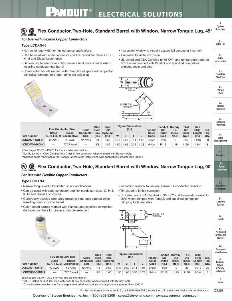
For technical assistance in the U.S., call 866-405-6654 (outside the U.S., see inside back cover for directory)
ELECTRICAL SOLUTIONS
D2.89
B2.Cable
Accessories
C1.Wiring
Duct
C3.Abrasion
Protection
C4.Cable
Management
D1.Terminals
D2.Power
Connectors
E1.LabelingSystems
E2.Labels
E3.Pre-Printed & Write-On
Markers
F.Index
B3.StainlessSteel Ties
C2.Surface
Raceway
E5.Lockout/Tagout
& SafetySolutions
B1.Cable Ties
A.System
Overview
D3.GroundingConnectors
E4.Permanent
Identification
Flex Conductor, Two-Hole, Standard Barrel with Window, Narrow Tongue Lug, 45°
‡See pages D3.70 – D3.73 for tool and die information.*Not UL Listed or CSA Certified with Class K flex conductor when crimped with Burndy tools.**Consult cable manufacturer for voltage stress relief instructions with applications greater than 2000 V.
Flex Conductor, Two-Hole, Standard Barrel with Window, Narrow Tongue Lug, 90°
‡See pages D3.70 – D3.73 for tool and die information.*Not UL Listed or CSA Certified with class K flex conductor when crimped with Burndy tools.**Consult cable manufacturer for voltage stress relief instructions with applications greater than 2000 V.
• Narrow tongue width for limited space applications
• Can be used with code conductor and flex conductor class: G, H, I,K, M and Diesel Locomotive
• Generously beveled wire entry prevents bent back strands wheninserting conductor into barrel
• Color-coded barrels marked with Panduit and specified competitordie index numbers for proper crimp die selection
• Inspection window to visually assure full conductor insertion
• Tin-plated to inhibit corrosion
• UL Listed and CSA Certified to 35 KV** and temperature rated to90°C when crimped with Panduit and specified competitorcrimping tools and dies
TL
INSPECTIONWINDOW
45˚
B
HOLESPACING
W
For Use with Flexible Copper Conductors
Type LCDXN-H
• Narrow tongue width for limited space applications
• Can be used with code conductor and flex conductor class: G, H, I,K, M and Diesel Locomotive
• Generously beveled wire entry prevents bent back strands wheninserting conductor into barrel
• Color-coded barrels marked with Panduit and specified competitordie index numbers for proper crimp die selection
• Inspection window to visually assure full conductor insertion
• Tin-plated to inhibit corrosion
• UL Listed and CSA Certified to 35 KV** and temperature rated to90°C when crimped with Panduit and specified competitorcrimping tools and dies
90˚
INSPECTIONWINDOWW
HOLESPACING
T
L
B
For Use with Flexible Copper Conductors
Type LCDXN-F
Part Number
Flex Conductor Size CodeConductor
Size
Stud Hole Size (In.)
Stud Hole
Spacing (In.)
Figure Dimensions (In.) Panduit
Color Code
Panduit Die
Index No.‡
Burndy Die
Index No.‡
T&B Die
Index No.‡
WireStrip
Length (In.)
Std.Pkg.Qty.
Class G, H, I, K, M
DieselLocomotive W B T L
LCDXN2-14AH-E* #2 AWG #2 AWG #2 AWG 1/4 0.63 0.47 0.59 0.11 1.92 Brown P33 10 33 11/16 20
LCDXN750-38DH-3 — 777.7 kcmil — 3/8 1.00 1.50 1.66 0.35 4.22 Yellow P115 L115 115H 1 3/4 3
Part Number
Flex Conductor Size Code Conductor
Size
Stud Hole Size (In.)
Stud Hole
Spacing (In.)
Figure Dimensions (In.) Panduit
Color Code
Panduit Die
Index No.‡
Burndy Die
Index No.‡
T&B Die
Index No.‡
WireStrip
Length (In.)
Std.Pkg.Qty.
Class G, H, I, K, M
DieselLocomotive W B T L
LCDXN2-14AF-E* #2 AWG #2 AWG #2 AWG 1/4 0.63 0.47 0.59 0.11 1.94 Brown P33 10 33 11/16 20
LCDXN750-38DF-3 — 777.7 kcmil — 3/8 1.00 1.50 1.66 0.35 3.76 Yellow P115 L115 115H 1 3/4 3
Courtesy of Steven Engineering, Inc. - (800) 258-9200 - [email protected] - www.stevenengineering.com

ELECTRICAL SOLUTIONS
Order number of pieces required, in multiples of Standard Package Quantity. Prime items appear in BOLD.D2.90
B2.Cable
Accessories
C1.Wiring
Duct
C3.Abrasion
Protection
C4.Cable
Management
D1.Terminals
D2.Power
Connectors
E1.LabelingSystems
E2.Labels
E3.Pre-Printed & Write-On
Markers
F.Index
B3.StainlessSteel Ties
C2.Surface
Raceway
E5.Lockout/Tagout
& SafetySolutions
B1.Cable Ties
A.System
Overview
D3.GroundingConnectors
E4.Permanent
Identification
Flex Conductor, Two-Hole, Long Barrel with Window Lug
• Can be used with code conductor and flex conductor class: G, H, I,K, M and Diesel Locomotive
• Long barrel maximizes number of crimps and provides premiumwire pull-out strength and electrical performance
• Generously beveled wire entry prevents bent back strands wheninserting conductor into barrel
• Color-coded barrels marked with Panduit and specified competitordie index numbers for proper crimp die selection
• Inspection window to visually assure full conductor insertion
• Tin-plated to inhibit corrosion
• UL Listed and CSA Certified to 35 KV** and temperature rated to90°C when crimped with Panduit and specified competitorcrimping tools and dies
• Meets J-STD-607-A and TIA-942 requirements for networksystems grounding applications
• Available with NEMA hole sizes and spacing
For Use with Flexible, Extra-Flexible, and Code Stranded Copper Conductors
Type LCCX
‡See pages D3.70 – D3.73 for tool and die information.*Not UL Listed or CSA Certified with Class K flex conductor when crimped with Burndy tools.**Consult cable manufacturer for voltage stress relief instructions with applications greater than 2000 V.^Slotted lug, refer to Figure 2.◆NEMA hole sizes and spacing.
W
HOLESPACING
L
INSPECTIONWINDOW
T
B
W
HOLESPACING
T
L
INSPECTIONWINDOW
B
Figure 1 Figure 2: Slotted
Part Number
Flex Conductor Size Code Conductor
Size
StudHoleSize(In.)
StudHole
Spacing(In.)
Figure Dimensions (In.) Panduit
Color Code
Panduit Die
Index No.‡
Burndy Die
Index No.‡
T&B Die
Index No.‡
WireStrip
Length (In.)
Std.Pkg.Qty.
Class G, H, I, K, M
DieselLocomotive W B T L
LCCX8-10A-L
#8 AWG #8 AWG #8 AWG
#10 0.63 0.41 0.70 0.08 2.01 Red P21 49 21 3/4 50
LCCX8-10B-L #10 0.75 0.41 0.70 0.08 2.14 Red P21 49 21 3/4 50
LCCX8-10AB-L^ #10 0.63 – 0.75 0.41 0.70 0.08 2.14 Red P21 49 21 3/4 50
LCCX8-14A-L 1/4 0.63 0.48 0.70 0.07 2.10 Red P21 49 21 3/4 50
LCCX8-14B-L 1/4 0.75 0.48 0.70 0.07 2.23 Red P21 49 21 3/4 50
LCCX8-14AB-L^ 1/4 0.63 – 0.75 0.48 0.70 0.07 2.23 Red P21 49 21 3/4 50
LCCX8-14D-L 1/4 1.00 0.48 0.70 0.07 2.48 Red P21 49 21 3/4 50
LCCX8-38D-L 3/8 1.00 0.60 0.70 0.05 2.70 Red P21 49 21 3/4 50
LCCX6-10B-L
#6 AWG #6 AWG #6 AWG
#10 0.75 0.46 1.07 0.08 2.52 Blue P24 7 24 1 1/8 50
LCCX6-14A-L 1/4 0.63 0.48 1.07 0.08 2.49 Blue P24 7 24 1 1/8 50
LCCX6-14B-L 1/4 0.75 0.48 1.07 0.08 2.61 Blue P24 7 24 1 1/8 50
LCCX6-14AB-L^ 1/4 0.63 – 0.75 0.48 1.07 0.08 2.61 Blue P24 7 24 1 1/8 50
LCCX6-14D-L 1/4 1.00 0.48 1.07 0.08 2.86 Blue P24 7 24 1 1/8 50
LCCX6-38A-L 3/8 0.63 0.62 1.07 0.06 2.71 Blue P24 7 24 1 1/8 50
LCCX6-38C-L 3/8 0.88 0.62 1.07 0.06 2.96 Blue P24 7 24 1 1/8 50
LCCX6-38AC-L^ 3/8 0.63 – 0.88 0.62 1.07 0.06 2.96 Blue P24 7 24 1 1/8 50
LCCX6-38D-L 3/8 1.00 0.62 1.07 0.06 3.08 Blue P24 7 24 1 1/8 50
LCCX4-14A-L
#4 AWG #5, #4, #3AWG #4 AWG
1/4 0.63 0.55 1.05 0.09 2.49 Gray P29 8 29 1 1/8 50
LCCX4-14B-L 1/4 0.75 0.55 1.05 0.09 2.63 Gray P29 8 29 1 1/8 50
LCCX4-14AB-L^ 1/4 0.63 – 0.75 0.55 1.05 0.09 2.63 Gray P29 8 29 1 1/8 50
LCCX4-14CE-L^ 1/4 0.88 – 1.25 0.55 1.05 0.09 3.12 Gray P29 8 29 1 1/8 50
LCCX4-38B-L 3/8 0.75 0.62 1.05 0.08 2.84 Gray P29 8 29 1 1/8 50
LCCX4-38D-L 3/8 1.00 0.62 1.05 0.08 3.09 Gray P29 8 29 1 1/8 50
LCCX4-38BD-L^ 3/8 0.75 – 1.00 0.62 1.05 0.08 3.09 Gray P29 8 29 1 1/8 50
Courtesy of Steven Engineering, Inc. - (800) 258-9200 - [email protected] - www.stevenengineering.com

LTBWDiesel
LocomotiveClass
G, H, I, K, M
Std.Pkg.Qty.
WireStrip
Length (In.)
T&B Die
Index No.‡
Burndy Die
Index No.‡
Panduit Die
Index No.‡
Panduit Color Code
Figure Dimensions (In.)
StudHole
Spacing(In.)
StudHoleSize(In.)
Code Conductor
Size
Flex Conductor Size
Part Number
For technical assistance in the U.S., call 866-405-6654 (outside the U.S., see inside back cover for directory)
ELECTRICAL SOLUTIONS
D2.91
B2.Cable
Accessories
C1.Wiring
Duct
C3.Abrasion
Protection
C4.Cable
Management
D1.Terminals
D2.Power
Connectors
E1.LabelingSystems
E2.Labels
E3.Pre-Printed & Write-On
Markers
F.Index
B3.StainlessSteel Ties
C2.Surface
Raceway
E5.Lockout/Tagout
& SafetySolutions
B1.Cable Ties
A.System
Overview
D3.GroundingConnectors
E4.Permanent
Identification
‡See pages D3.70 – D3.73 for tool and die information.*Not UL Listed or CSA Certified with Class K flex conductor when crimped with Burndy tools.**Consult cable manufacturer for voltage stress relief instructions with applications greater than 2000 V.^Slotted lug, refer to Figure 2.◆NEMA hole sizes and spacing.
Flex Conductor, Two-Hole, Long Barrel with Window Lug (continued)
LCCX2-14A-E*
#2 AWG #2 AWG #2 AWG
1/4 0.63 0.70 1.36 0.11 2.89 Brown P33 10 33 1 7/16 20
LCCX2-14B-E* 1/4 0.75 0.70 1.36 0.11 3.01 Brown P33 10 33 1 7/16 20
LCCX2-38D-E* 3/8 1.00 0.70 1.36 0.11 3.46 Brown P33 10 33 1 7/16 20
LCCX2-12-E* 1/2 1.75 0.75 1.36 0.09 4.63 Brown P33 10 33 1 7/16 20
LCCX1-14A-X
#1 AWG #1 AWG #1 AWG
1/4 0.63 0.76 1.44 0.12 3.07 Green P37 11 37 1 1/2 10
LCCX1-14B-X 1/4 0.75 0.76 1.44 0.12 3.19 Green P37 11 37 1 1/2 10
LCCX1-14D-X 1/4 1.00 0.76 1.44 0.12 3.44 Green P37 11 37 1 1/2 10
LCCX1-56C-X 5/16 0.88 0.76 1.44 0.12 3.37 Green P37 11 37 1 1/2 10
LCCX1-56D-X 5/16 1.00 0.76 1.44 0.12 3.50 Green P37 11 37 1 1/2 10
LCCX1-38D-X 3/8 1.00 0.76 1.44 0.12 3.57 Green P37 11 37 1 1/2 10
LCCX1/0-14A-X
1/0 AWG 1/0 AWG 1/0 AWG
1/4 0.63 0.85 1.50 0.13 3.23 Pink P42 12 42 1 9/16 10
LCCX1/0-14B-X 1/4 0.75 0.85 1.50 0.13 3.36 Pink P42 12 42 1 9/16 10
LCCX1/0-38D-X 3/8 1.00 0.85 1.50 0.13 3.67 Pink P42 12 42 1 9/16 10
LCCX1/0-12-X 1/2 1.75 0.85 1.50 0.13 4.83 Pink P42 12 42 1 9/16 10
LCCX2/0-14A-X
2/0 AWG 2/0 AWG 2/0 AWG
1/4 0.63 0.96 1.50 0.13 3.27 Black P45 13 45 1 9/16 10
LCCX2/0-14B-X 1/4 0.75 0.96 1.50 0.13 3.39 Black P45 13 45 1 9/16 10
LCCX2/0-38D-X 3/8 1.00 0.96 1.50 0.13 3.70 Black P45 13 45 1 9/16 10
LCCX2/0-12-X 1/2 1.75 0.96 1.50 0.13 4.87 Black P45 13 45 1 9/16 10
LCCX3/0-14B-X3/0 AWG 3/0 AWG 3/0 AWG
1/4 0.75 1.06 1.56 0.14 3.48 Orange P50 14 50 1 5/8 10
LCCX3/0-38D-X 3/8 1.00 1.06 1.56 0.14 3.81 Orange P50 14 50 1 5/8 10
LCCX4/0-14B-X
4/0 AWG 4/0 AWG 4/0 AWG
1/4 0.75 1.19 2.24 0.16 4.07 Purple P54 15 54 2 5/16 10
LCCX4/0-38D-X 3/8 1.00 1.19 2.24 0.16 4.55 Purple P54 15 54 2 5/16 10
◆ LCCX4/0-12-X 1/2 1.75 1.19 2.24 0.16 5.73 Purple P54 15 54 2 5/16 10
LCCX250-14B-X
250 kcmil 262.6 kcmil —
1/4 0.75 1.28 2.24 0.17 4.11 Yellow P62 16 62 2 5/16 10
LCCX250-38D-X 3/8 1.00 1.28 2.24 0.17 4.59 Yellow P62 16 62 2 5/16 10
◆ LCCX250-12-X 1/2 1.75 1.28 2.24 0.17 5.77 Yellow P62 16 62 2 5/16 10
LCCX300-38D-6 300 kcmil 313.1 kcmil — 3/8 1.00 1.39 2.30 0.18 4.67 Red P71 18 71H 2 3/8 6
LCCX300-12-6 300 kcmil 313.1 kcmil — 1/2 1.75 1.39 2.30 0.18 5.85 Red P71 18 71H 2 3/8 6
LCCX350-14B-6
350 kcmil 373.7 kcmil —
1/4 0.75 1.54 2.50 0.22 4.47 Blue P76 19 76H 2 9/16 6
LCCX350-38D-6 3/8 1.00 1.54 2.50 0.22 4.95 Blue P76 19 76H 2 9/16 6
◆ LCCX350-12-6 1/2 1.75 1.54 2.50 0.22 6.13 Blue P76 19 76H 2 9/16 6
◆ LCCX450-12-6 450 kcmil 444.4 kcmil — 1/2 1.75 1.70 2.69 0.26 6.37 Brown P87 20 87 2 3/4 6
LCCX500-38D-6500 kcmil 535.3 kcmil —
3/8 1.00 1.89 2.88 0.26 5.72 Pink P99 L99 99H 2 15/16 6
◆ LCCX500-12-6 1/2 1.75 1.89 2.88 0.26 6.66 Pink P99 L99 99H 2 15/16 6
◆ LCCX650-12-6 — 646.4 kcmil — 1/2 1.75 1.95 2.94 0.30 6.75 Black P106 24 106H 3.00 6
Courtesy of Steven Engineering, Inc. - (800) 258-9200 - [email protected] - www.stevenengineering.com

ELECTRICAL SOLUTIONS
Order number of pieces required, in multiples of Standard Package Quantity. Prime items appear in BOLD.D2.92
B2.Cable
Accessories
C1.Wiring
Duct
C3.Abrasion
Protection
C4.Cable
Management
D1.Terminals
D2.Power
Connectors
E1.LabelingSystems
E2.Labels
E3.Pre-Printed & Write-On
Markers
F.Index
B3.StainlessSteel Ties
C2.Surface
Raceway
E5.Lockout/Tagout
& SafetySolutions
B1.Cable Ties
A.System
Overview
D3.GroundingConnectors
E4.Permanent
Identification
Flex Conductor, Two-Hole, Long Barrel with Window Lug, 45° Angle
• Can be used with code conductor and flex conductor class: G, H, I,K, M and Diesel Locomotive
• Long barrel maximizes number of crimps and provides premiumwire pull-out strength and electrical performance
• Generously beveled wire entry prevents bent back strands wheninserting conductor into barrel
• Color-coded barrels marked with Panduit and specified competitordie index numbers for proper crimp die selection
• Inspection window to visually assure full conductor insertion
• Tin-plated to inhibit corrosion
• UL Listed and CSA Certified to 35 KV** and temperature rated to90°C when crimped with Panduit and specified competitorcrimping tools and dies
• Meets J-STD-607-A and TIA-942 requirements for networksystems grounding applications
• Available with NEMA hole sizes and spacing
45˚
HOLESPACING
W
T
INSPECTIONWINDOW
B
L
For Use with Flexible, Extra-Flexible, and Code Stranded Copper Conductors
Type LCCX-H
‡See pages D3.70 – D3.73 for tool and die information.*Not UL Listed or CSA Certified with Class K flex conductor when crimped with Burndy tools.**Consult cable manufacturer for voltage stress relief instructions with applications greater than 2000 V.◆NEMA hole sizes and spacing.
Part Number
Flex Conductor Size CodeConductor
Size
StudHoleSize(In.)
StudHole
Spacing(In.)
Figure Dimensions(In.) Panduit
ColorCode
PanduitDie Index
No.‡
BurndyDie
IndexNo.‡
T&BDie
IndexNo.‡
WireStrip
Length(In.)
Std.Pkg.Qty.
Class G,H, I, K, M
DieselLocomotive W B T L
LCCX8-10AH-L
#8 AWG #8 AWG #8 AWG
#10 0.63 0.41 0.70 0.08 1.82 Red P21 49 21 3/4 50
LCCX8-10BH-L #10 0.75 0.41 0.70 0.08 1.95 Red P21 49 21 3/4 50
LCCX8-14AH-L 1/4 0.63 0.48 0.70 0.07 1.91 Red P21 49 21 3/4 50
LCCX8-14BH-L 1/4 0.75 0.48 0.70 0.07 2.03 Red P21 49 21 3/4 50
LCCX8-14DH-L 1/4 1.00 0.48 0.70 0.07 2.28 Red P21 49 21 3/4 50
LCCX8-38DH-L 3/8 1.00 0.60 0.70 0.05 2.49 Red P21 49 21 3/4 50
LCCX6-10BH-L
#6 AWG #6 AWG #6 AWG
#10 0.75 0.46 1.07 0.08 2.22 Blue P24 7 24 1 1/8 50
LCCX6-14AH-L 1/4 0.63 0.48 1.07 0.08 2.18 Blue P24 7 24 1 1/8 50
LCCX6-14BH-L 1/4 0.75 0.48 1.07 0.08 2.31 Blue P24 7 24 1 1/8 50
LCCX6-14DH-L 1/4 1.00 0.48 1.07 0.08 2.56 Blue P24 7 24 1 1/8 50
LCCX6-38AH-L 3/8 0.63 0.62 1.07 0.06 2.39 Blue P24 7 24 1 1/8 50
LCCX6-38CH-L 3/8 0.88 0.62 1.07 0.06 2.64 Blue P24 7 24 1 1/8 50
LCCX6-38DH-L 3/8 1.00 0.62 1.07 0.06 2.77 Blue P24 7 24 1 1/8 50
LCCX4-14AH-L
#4 AWG #5, #4, #3AWG #4 AWG
1/4 0.63 0.55 1.05 0.09 2.20 Gray P29 8 29 1 1/8 50
LCCX4-14BH-L 1/4 0.75 0.55 1.05 0.09 2.32 Gray P29 8 29 1 1/8 50
LCCX4-38BH-L 3/8 0.75 0.62 1.05 0.08 2.54 Gray P29 8 29 1 1/8 50
LCCX4-38DH-L 3/8 1.00 0.62 1.05 0.08 2.79 Gray P29 8 29 1 1/8 20
LCCX2-14AH-E
#2 AWG #2 AWG #2 AWG
1/4 0.63 0.70 1.36 0.11 2.46 Brown P33 10 33 1 7/16 20
LCCX2-14BH-E 1/4 0.75 0.70 1.36 0.11 2.58 Brown P33 10 33 1 7/16 20
LCCX2-38DH-E 3/8 1.00 0.70 1.36 0.11 3.04 Brown P33 10 33 1 7/16 20
LCCX2-12H-E 1/2 1.75 0.75 1.36 0.09 4.20 Brown P33 10 33 1 7/16 10
LCCX1-14AH-X
#1 AWG #1 AWG #1 AWG
1/4 0.63 0.76 1.44 0.12 2.61 Green P37 11 37 1 1/2 10
LCCX1-14BH-X 1/4 0.75 0.76 1.44 0.12 2.73 Green P37 11 37 1 1/2 10
LCCX1-14DH-X 1/4 1.00 0.76 1.44 0.12 2.98 Green P37 11 37 1 1/2 10
LCCX1-56CH-X 5/16 0.88 0.76 1.44 0.12 2.91 Green P37 11 37 1 1/2 10
LCCX1-56DH-X 5/16 1.00 0.76 1.44 0.12 3.04 Green P37 11 37 1 1/2 10
LCCX1-38DH-X 3/8 1.00 0.76 1.44 0.12 3.11 Green P37 11 37 1 1/2 10
Courtesy of Steven Engineering, Inc. - (800) 258-9200 - [email protected] - www.stevenengineering.com

For technical assistance in the U.S., call 866-405-6654 (outside the U.S., see inside back cover for directory)
ELECTRICAL SOLUTIONS
D2.93
B2.Cable
Accessories
C1.Wiring
Duct
C3.Abrasion
Protection
C4.Cable
Management
D1.Terminals
D2.Power
Connectors
E1.LabelingSystems
E2.Labels
E3.Pre-Printed & Write-On
Markers
F.Index
B3.StainlessSteel Ties
C2.Surface
Raceway
E5.Lockout/Tagout
& SafetySolutions
B1.Cable Ties
A.System
Overview
D3.GroundingConnectors
E4.Permanent
Identification
‡See pages D3.70 – D3.73 for tool and die information.*Not UL Listed or CSA Certified with Class K flex conductor when crimped with Burndy tools.**Consult cable manufacturer for voltage stress relief instructions with applications greater than 2000 V.◆NEMA hole sizes and spacing.
Flex Conductor, Two-Hole, Long Barrel with Window Lug, 45° Angle (continued)
Part Number
Flex Conductor Size CodeConductor
Size
StudHoleSize(In.)
StudHole
Spacing(In.)
Figure Dimensions(In.) Panduit
ColorCode
PanduitDie Index
No.‡
BurndyDie
IndexNo.‡
T&BDie
IndexNo.‡
WireStrip
Length(In.)
Std.Pkg.Qty.
Class G,H, I, K, M
DieselLocomotive W B T L
LCCX1/0-14AH-X
1/0 AWG 1/0 AWG 1/0 AWG
1/4 0.63 0.85 1.50 0.13 2.76 Pink P42 12 42 1 9/16 10
LCCX1/0-14BH-X 1/4 0.75 0.85 1.50 0.13 2.88 Pink P42 12 42 1 9/16 10
LCCX1/0-38DH-X 3/8 1.00 0.85 1.50 0.13 3.20 Pink P42 12 42 1 9/16 10
LCCX1/0-12H-X 1/2 1.75 0.85 1.50 0.13 4.36 Pink P42 12 42 1 9/16 10
LCCX2/0-14AH-X
2/0 AWG 2/0 AWG 2/0 AWG
1/4 0.63 0.96 1.50 0.13 2.78 Black P45 13 45 1 9/16 10
LCCX2/0-14BH-X 1/4 0.75 0.96 1.50 0.13 2.91 Black P45 13 45 1 9/16 10
LCCX2/0-38DH-X 3/8 1.00 0.96 1.50 0.13 3.22 Black P45 13 45 1 9/16 10
LCCX2/0-12H-X 1/2 1.75 0.96 1.50 0.13 4.38 Black P45 13 45 1 9/16 10
LCCX3/0-14BH-X3/0 AWG 3/0 AWG 3/0 AWG
1/4 0.75 1.06 1.56 0.14 2.98 Orange P50 14 50 1 5/8 10
LCCX3/0-38DH-X 3/8 1.00 1.06 1.56 0.14 3.31 Orange P50 14 50 1 5/8 10
LCCX4/0-14BH-X
4/0 AWG 4/0 AWG 4/0 AWG
1/4 0.75 1.19 2.24 0.16 3.45 Purple P54 15 54 2 5/16 10
LCCX4/0-38DH-X 3/8 1.00 1.19 2.24 0.16 3.93 Purple P54 15 54 2 5/16 10
◆ LCCX4/0-12H-X 1/2 1.75 1.19 2.24 0.16 5.11 Purple P54 15 54 2 5/16 10
LCCX250-14BH-X250 kcmil 262.6 kcmil —
1/4 0.75 1.28 2.24 0.17 3.48 Yellow P62 16 62 2 5/16 10
LCCX250-38DH-X 3/8 1.00 1.28 2.24 0.17 3.96 Yellow P62 16 62 2 5/16 6
LCCX300-38DH-6 300 kcmil 313.1 kcmil — 3/8 1.00 1.39 2.30 0.18 4.07 Red P71 18 71H 2 3/8 6
LCCX300-12H-6 300 kcmil 313.1 kcmil — 1/2 1.75 1.39 2.30 0.18 3.81 Red P71 18 71H 2 3/8 6
LCCX350-14BH-6
350 kcmil 373.7 kcmil —
1/4 0.75 1.54 2.50 0.22 3.81 Blue P76 19 76H 2 9/16 6
LCCX350-38DH-6 3/8 1.00 1.54 2.50 0.22 4.29 Blue P76 19 76H 2 9/16 6
◆ LCCX350-12H-6 1/2 1.75 1.54 2.50 0.22 5.47 Blue P76 19 76H 2 9/16 6
Courtesy of Steven Engineering, Inc. - (800) 258-9200 - [email protected] - www.stevenengineering.com

ELECTRICAL SOLUTIONS
Order number of pieces required, in multiples of Standard Package Quantity. Prime items appear in BOLD.D2.94
B2.Cable
Accessories
C1.Wiring
Duct
C3.Abrasion
Protection
C4.Cable
Management
D1.Terminals
D2.Power
Connectors
E1.LabelingSystems
E2.Labels
E3.Pre-Printed & Write-On
Markers
F.Index
B3.StainlessSteel Ties
C2.Surface
Raceway
E5.Lockout/Tagout
& SafetySolutions
B1.Cable Ties
A.System
Overview
D3.GroundingConnectors
E4.Permanent
Identification
Flex Conductor, Two-Hole, Long Barrel with Window Lug, 90° Angle
• Can be used with code conductor and flex conductor class: G, H, I,K, M and Diesel Locomotive
• Long barrel maximizes number of crimps and provides premiumwire pull-out strength and electrical performance
• Generously beveled wire entry prevents bent back strands wheninserting conductor into barrel
• Color-coded barrels marked with Panduit and specified competitordie index numbers for proper crimp die selection
• Inspection window to visually assure full conductor insertion
• Tin-plated to inhibit corrosion
• UL Listed and CSA Certified to 35 KV** and temperature rated to90°C when crimped with Panduit and specified competitorcrimping tools and dies
• Meets J-STD-607-A and TIA-942 requirements for networksystems grounding applications
• Available with NEMA hole sizes and spacing
90˚
W INSPECTIONWINDOW
HOLESPACING
T
B
L
For Use with Flexible, Extra-Flexible, and Code Stranded Copper Conductors
Type LCCX-F
‡See pages D3.70 – D3.73 for tool and die information.*Not UL Listed or CSA Certified with Class K flex conductor when crimped with Burndy tools.**Consult cable manufacturer for voltage stress relief instructions with applications greater than 2000 V.
Part Number
Flex Conductor Size CodeConductor
Size
StudHoleSize (In.)
StudHole
Spacing(In.)
Figure Dimensions(In.) Panduit
ColorCode
PanduitDie Index
No.‡
BurndyDie
IndexNo.
T&BDie
IndexNo.
WireStrip
Length(In.)
Std.Pkg.Qty.
Class G,H, I, K, M
DieselLocomotive W B T L
LCCX8-10AF-L
#8 AWG #8 AWG #8 AWG
#10 0.63 0.41 0.70 0.08 1.53 Red P21 49 21 3/4 50
LCCX8-10BF-L #10 0.75 0.41 0.70 0.08 1.65 Red P21 49 21 3/4 50
LCCX8-14AF-L 1/4 0.63 0.48 0.70 0.07 1.62 Red P21 49 21 3/4 50
LCCX8-14BF-L 1/4 0.75 0.48 0.70 0.07 1.74 Red P21 49 21 3/4 50
LCCX8-14DF-L 1/4 1.00 0.48 0.70 0.07 1.99 Red P21 49 21 3/4 50
LCCX8-38DF-L 3/8 1.00 0.60 0.70 0.05 2.21 Red P21 49 21 3/4 50
LCCX6-10BF-L
#6 AWG #6 AWG #6 AWG
#10 0.75 0.46 1.07 0.08 1.69 Blue P24 7 24 1 1/8 50
LCCX6-14AF-L 1/4 0.63 0.48 1.07 0.08 1.66 Blue P24 7 24 1 1/8 50
LCCX6-14BF-L 1/4 0.75 0.48 1.07 0.08 1.78 Blue P24 7 24 1 1/8 50
LCCX6-14DF-L 1/4 1.00 0.48 1.07 0.08 2.03 Blue P24 7 24 1 1/8 50
LCCX6-38AF-L 3/8 0.63 0.62 1.07 0.06 1.88 Blue P24 7 24 1 1/8 50
LCCX6-38CF-L 3/8 0.88 0.62 1.07 0.06 2.13 Blue P24 7 24 1 1/8 50
LCCX6-38DF-L 3/8 1.00 0.62 1.07 0.06 2.25 Blue P24 7 24 1 1/8 50
LCCX4-14AF-L
#4 AWG #5, #4, #3AWG #4 AWG
1/4 0.63 0.55 1.05 0.09 1.74 Gray P29 8 29 1 1/8 50
LCCX4-14BF-L 1/4 0.75 0.55 1.05 0.09 1.87 Gray P29 8 29 1 1/8 50
LCCX4-38BF-L 3/8 0.75 0.62 1.05 0.08 2.09 Gray P29 8 29 1 1/8 50
LCCX4-38DF-L 3/8 1.00 0.62 1.05 0.08 2.34 Gray P29 8 29 1 1/8 50
LCCX2-14AF-E
#2 AWG #2 AWG #2 AWG
1/4 0.63 0.70 1.36 0.11 1.94 Brown P33 10 33 1 7/16 20
LCCX2-14BF-E 1/4 0.75 0.70 1.36 0.11 2.06 Brown P33 10 33 1 7/16 20
LCCX2-38DF-E 3/8 1.00 0.70 1.36 0.11 2.51 Brown P33 10 33 1 7/16 20
LCCX2-12F-E 1/2 1.75 0.75 1.36 0.09 3.68 Brown P33 10 33 1 7/16 20
LCCX1-14AF-X
#1 AWG #1 AWG #1 AWG
1/4 0.63 0.76 1.44 0.12 2.08 Green P37 11 37 1 1/2 10
LCCX1-14BF-X 1/4 0.75 0.76 1.44 0.12 2.20 Green P37 11 37 1 1/2 10
LCCX1-14DF-X 1/4 1.00 0.76 1.44 0.12 2.45 Green P37 11 37 1 1/2 10
LCCX1-56CF-X 5/16 0.88 0.76 1.44 0.12 2.38 Green P37 11 37 1 1/2 10
LCCX1-56DF-X 5/16 1.00 0.76 1.44 0.12 2.51 Green P37 11 37 1 1/2 10
LCCX1-38DF-X 3/8 1.00 0.76 1.44 0.12 2.58 Green P37 11 37 1 1/2 10
LCCX1/0-14AF-X
1/0 AWG 1/0 AWG 1/0 AWG
1/4 0.63 0.85 1.50 0.13 2.22 Pink P42 12 42 1 9/16 10
LCCX1/0-14BF-X 1/4 0.75 0.85 1.50 0.13 2.34 Pink P42 12 42 1 9/16 10
LCCX1/0-38DF-X 3/8 1.00 0.85 1.50 0.13 2.66 Pink P42 12 42 1 9/16 10
LCCX1/0-12F-X 1/2 1.75 0.85 1.50 0.13 3.82 Pink P42 12 42 1 9/16 10
Courtesy of Steven Engineering, Inc. - (800) 258-9200 - [email protected] - www.stevenengineering.com

For technical assistance in the U.S., call 866-405-6654 (outside the U.S., see inside back cover for directory)
ELECTRICAL SOLUTIONS
D2.95
B2.Cable
Accessories
C1.Wiring
Duct
C3.Abrasion
Protection
C4.Cable
Management
D1.Terminals
D2.Power
Connectors
E1.LabelingSystems
E2.Labels
E3.Pre-Printed & Write-On
Markers
F.Index
B3.StainlessSteel Ties
C2.Surface
Raceway
E5.Lockout/Tagout
& SafetySolutions
B1.Cable Ties
A.System
Overview
D3.GroundingConnectors
E4.Permanent
Identification
• Narrow tongue width for limited space applications
• Can be used with flex conductor class: G, H, I, K, M and DieselLocomotive
• Long barrel maximizes number of crimps and provides premiumwire pull-out strength and electrical performance
• Generously beveled wire entry prevents bent back strands wheninserting conductor into barrel
• Color-coded barrels marked with Panduit and specified competitordie index numbers for proper crimp die selection
• Inspection window to visually assure full conductor insertion
• Tin-plated to inhibit corrosion
• UL Listed and CSA Certified to 35 KV** and temperature rated to90°C when crimped with Panduit and specified competitorcrimping tools and dies
• Meets J-STD-607-A and TIA-942 requirements for networksystems grounding applications
• Available with NEMA hole sizes and spacing
BINSPECTION
WINDOW
T
W
L
HOLESPACING
‡See pages D3.70 – D3.73 for tool and die information.*Not UL Listed or CSA Certified with Class K flex conductor when crimped with Burndy tools.**Consult cable manufacturer for voltage stress relief instructions with applications greater than 2000 V.◆NEMA hole sizes and spacing.
Flex Conductor, Two-Hole, Long Barrel with Window Lug, 90° Angle (continued)
Flex Conductor, Two-Hole, Long Barrel with Window, NarrowTongue Lug
‡See pages D3.70 – D3.73 for tool and die information.**Consult cable manufacturer for voltage stress relief instructions with applications greater than 2000 V.◆NEMA hole sizes and spacing.
For use with Flexible and Extra-Flexible Stranded Copper Copper Conductors
Part Number
Flex Conductor Size Stud Hole Size (In.)
Stud Hole
Spacing (In.)
Figure Dimensions (In.)
Panduit Color Code
Panduit Die Index
No.‡
Burndy Die
Index No.‡
T&B Die
Index No.‡
WireStrip
Length (In.)
Std.Pkg.Qty.
Class G,H, I, K, M
Diesel Locomotive W B T L
◆ LCCXN450-12-6 450 kcmil 444.4 kcmil 1/2 1.75 1.19 2.69 0.33 6.41 Brown P87 20 87H 2 3/4 6
◆ LCCXN500-12-6 500 kcmil 535.3 kcmil 1/2 1.75 1.30 2.88 0.32 6.71 Pink P99 L99 99H 2 15/16 6
◆ LCCXN650-12-6 — 646.4 kcmil 1/2 1.75 1.35 2.94 0.36 6.78 Black P106 24 106 3 6
Part Number
Flex Conductor Size CodeConductor
Size
StudHoleSize (In.)
StudHole
Spacing(In.)
Figure Dimensions(In.) Panduit
ColorCode
PanduitDie Index
No.‡
BurndyDie
IndexNo.
T&BDie
IndexNo.
WireStrip
Length(In.)
Std.Pkg.Qty.
Class G,H, I, K, M
DieselLocomotive W B T L
LCCX2/0-14AF-X
2/0 AWG 2/0 AWG 2/0 AWG
1/4 0.63 0.96 1.50 0.13 2.29 Black P45 13 45 1 9/16 10
LCCX2/0-14BF-X 1/4 0.75 0.96 1.50 0.13 2.42 Black P45 13 45 1 9/16 10
LCCX2/0-38DF-X 3/8 1.00 0.96 1.50 0.13 2.73 Black P45 13 45 1 9/16 10
LCCX2/0-12F-X 1/2 1.75 0.96 1.50 0.13 3.89 Black P45 13 45 1 9/16 10
LCCX3/0-14BF-X3/0 AWG 3/0 AWG 3/0 AWG
1/4 0.75 1.06 1.56 0.14 2.50 Orange P50 14 50 1 5/8 10
LCCX3/0-38DF-X 3/8 1.00 1.06 1.56 0.14 2.84 Orange P50 14 50 1 5/8 10
LCCX4/0-14BF-X
4/0 AWG 4/0 AWG 4/0 AWG
1/4 0.75 1.19 2.24 0.16 2.69 Purple P54 15 54 2 5/16 10
LCCX4/0-38DF-X 3/8 1.00 1.19 2.24 0.16 2.88 Purple P54 15 54 2 5/16 10◆ LCCX4/0-12F-X 1/2 1.75 1.19 2.24 0.16 4.06 Purple P54 15 54 2 5/16 10
LCCX250-14BF-X250 kcmil 262.6 kcmil —
1/4 0.75 1.28 2.24 0.17 2.46 Yellow P62 16 62 2 5/16 10
LCCX250-38DF-X 3/8 1.00 1.28 2.24 0.17 2.94 Yellow P62 16 62 2 5/16 10
LCCX300-38DF-6300 kcmil 313.1 kcmil —
3/8 1.00 1.39 2.30 0.18 3.02 Red P71 18 71H 2 3/8 6
LCCX300-12F-6 1/2 1.75 1.39 2.30 0.18 3.95 Red P71 18 71H 2 3/8 6
LCCX350-14BF-6
350 kcmil 373.7 kcmil —
1/4 0.75 1.54 2.50 0.22 2.65 Blue P76 19 76H 2 9/16 6
LCCX350-38DF-6 3/8 1.00 1.54 2.50 0.22 3.13 Blue P76 19 76H 2 9/16 6◆ LCCX350-12F-6 1/2 1.75 1.54 2.50 0.22 4.31 Blue P76 19 76H 2 9/16 6
Courtesy of Steven Engineering, Inc. - (800) 258-9200 - [email protected] - www.stevenengineering.com

ELECTRICAL SOLUTIONS
Order number of pieces required, in multiples of Standard Package Quantity. Prime items appear in BOLD.D2.96
B2.Cable
Accessories
C1.Wiring
Duct
C3.Abrasion
Protection
C4.Cable
Management
D1.Terminals
D2.Power
Connectors
E1.LabelingSystems
E2.Labels
E3.Pre-Printed & Write-On
Markers
F.Index
B3.StainlessSteel Ties
C2.Surface
Raceway
E5.Lockout/Tagout
& SafetySolutions
B1.Cable Ties
A.System
Overview
D3.GroundingConnectors
E4.Permanent
Identification
Flex Conductor, Two-Hole, Long Barrel, Flared NEBS Lug
• Can be used with flex conductor class: K, M, and Diesel Locomotive
• Long barrel maximizes the number of crimps and providespremium wire pull-out strength and electrical performance
• Flared entry prevents bent back strands when inserting fine strandconductor into barrel
• Color-coded barrels marked with Panduit die index numbers forproper crimp die selection
• Enclosed barrel prevents corrosive material from entering barrelwhen used in harsh environments
• Tin-plated to inhibit corrosion
• UL Listed and CSA Certified to 35 KV** and temperature rated to90°C when crimped with Panduit crimping tools and dies
• Tested by Telcordia – meets NEBS Level 3
• Available with NEMA hole sizes and spacing
W
HOLESPACING
L
B
TFLAREDENTRY
For Use with Flexible and Extra-Flexible Copper Conductors
Type LCCF
‡See pages D3.74, D3.75 for tool and die information.**Consult cable manufacturer for voltage stress relief instructions with applications greater than 2000 V.◆NEMA hole sizes and spacing.
Part Number
Flex Conductor Size Stud HoleSize (In.)
Stud HoleSpacing
(In.)
Figure Dimensions (In.) PanduitColor Code
Panduit Die Index
No.‡
Wire StripLength
(In.)
Std.Pkg.Qty.
Class K and M
DieselLocomotive W B T L
LCCF8-14A-L
— #8 AWG
1/4 .63 .48 .76 .07 2.22 Red P21 13/16 50
LCCF8-14B-L 1/4 .75 .48 .76 .07 2.34 Red P21 13/16 50
LCCF8-38D-L 3/8 1.00 .60 .76 .05 2.81 Red P21 13/16 50
LCCF6-14A-L
#6 AWG #6 AWG
1/4 .63 .48 1.22 .08 2.71 Blue P24 1 5/16 50
LCCF6-14B-L 1/4 .75 .48 1.22 .08 2.83 Blue P24 1 5/16 50
LCCF6-38D-L 3/8 1.00 .62 1.22 .06 3.30 Blue P24 1 5/16 50
LCCF4-14A-L
#4 AWG #4 AWG
1/4 .63 .55 1.23 .09 2.75 Gray P29 1 5/16 50
LCCF4-14B-L 1/4 .75 .55 1.23 .09 2.88 Gray P29 1 5/16 50
LCCF4-38D-L 3/8 1.00 .62 1.23 .08 3.35 Gray P29 1 5/16 50
LCCF2-14A-E
#2 AWG #2 AWG
1/4 .63 .70 1.36 .11 3.00 Brown P33 1 7/16 20
LCCF2-14B-E 1/4 .75 .70 1.36 .11 3.12 Brown P33 1 7/16 20
LCCF2-56B-E 5/16 .75 .70 1.36 .11 3.25 Brown P33 1 7/16 20
LCCF2-38D-E 3/8 1.00 .70 1.36 .11 3.57 Brown P33 1 7/16 20
LCCF2-12-E 1/2 1.75 .75 1.36 .09 4.74 Brown P33 1 7/16 20
LCCF1-14A-X
#1 AWG #1 AWG
1/4 .63 .76 1.44 .12 3.18 Pink P42 1 1/2 10
LCCF1-14B-X 1/4 .75 .76 1.44 .12 3.31 Pink P42 1 1/2 10
LCCF1-56C-X 5/16 .88 .76 1.44 .12 3.49 Pink P42 1 1/2 10
LCCF1-38D-X 3/8 1.00 .76 1.44 .12 3.69 Pink P42 1 1/2 10
LCCF1-12-X 1/2 1.75 .80 1.44 .12 4.86 Pink P42 1 1/2 10
Courtesy of Steven Engineering, Inc. - (800) 258-9200 - [email protected] - www.stevenengineering.com

For technical assistance in the U.S., call 866-405-6654 (outside the U.S., see inside back cover for directory)
ELECTRICAL SOLUTIONS
D2.97
B2.Cable
Accessories
C1.Wiring
Duct
C3.Abrasion
Protection
C4.Cable
Management
D1.Terminals
D2.Power
Connectors
E1.LabelingSystems
E2.Labels
E3.Pre-Printed & Write-On
Markers
F.Index
B3.StainlessSteel Ties
C2.Surface
Raceway
E5.Lockout/Tagout
& SafetySolutions
B1.Cable Ties
A.System
Overview
D3.GroundingConnectors
E4.Permanent
Identification
LTBWDiesel
LocomotiveClass
K and M
Std.Pkg.Qty.
Wire StripLength
(In.)
Panduit Die Index
No.‡
PanduitColor Code
Figure Dimensions (In.)Stud HoleSpacing
(In.)
Stud HoleSize (In.)
Flex Conductor Size
Part Number
‡See pages D3.74, D3.75 for tool and die information.**Consult cable manufacturer for voltage stress relief instructions with applications greater than 2000 V.◆NEMA hole sizes and spacing.
Flex Conductor, Two-Hole, Long Barrel, Flared NEBS Lug (continued)
LCCF1/0-14A-X
1/0 AWG 1/0 AWG
1/4 .63 .85 1.50 .13 3.38 Black P45 1 9/16 10
LCCF1/0-14B-X 1/4 .75 .85 1.50 .13 3.51 Black P45 1 9/16 10
LCCF1/0-56C-X 5/16 .88 .85 1.50 .13 3.63 Black P45 1 9/16 10
LCCF1/0-38D-X 3/8 1.00 .85 1.50 .13 3.82 Black P45 1 9/16 10
LCCF1/0-12-X 1/2 1.75 .85 1.50 .13 4.98 Black P45 1 9/16 10
LCCF2/0-14A-X
2/0 AWG 2/0 AWG
1/4 .63 .96 1.50 .13 3.43 Orange P50 1 9/16 10
LCCF2/0-14B-X 1/4 .75 .96 1.50 .13 3.56 Orange P50 1 9/16 10
LCCF2/0-38D-X 3/8 1.00 .96 1.50 .13 3.87 Orange P50 1 9/16 10
LCCF2/0-12-X 1/2 1.75 .96 1.50 .13 5.03 Orange P50 1 9/16 10
LCCF3/0-14B-X
3/0 AWG 3/0 AWG
1/4 .75 1.06 1.56 .14 3.66 Purple P54 1 5/8 10
LCCF3/0-38D-X 3/8 1.00 1.06 1.56 .14 3.99 Purple P54 1 5/8 10
◆ LCCF3/0-12-X 1/2 1.75 1.06 1.56 .14 5.13 Purple P54 1 5/8 10
LCCF4/0-14B-X
4/0 AWG 4/0 AWG
1/4 .75 1.17 1.61 .14 3.60 Yellow P62 1 11/16 10
LCCF4/0-38D-X 3/8 1.00 1.17 1.61 .14 4.09 Yellow P62 1 11/16 10
LCCF4/0-38-X 3/8 1.75 1.17 1.61 .14 4.84 Yellow P62 1 11/16 10
◆ LCCF4/0-12-X 1/2 1.75 1.17 1.61 .14 5.23 Yellow P62 1 11/16 10
LCCF250-14B-X
250 kcmil 262.6 kcmil
1/4 .75 1.28 2.24 .17 4.33 White P66 2 5/16 10
LCCF250-38D-X 3/8 1.00 1.28 2.24 .17 4.81 White P66 2 5/16 10
LCCF250-12E-X 1/2 1.25 1.28 2.24 .17 5.49 White P66 2 5/16 10
◆ LCCF250-12-X 1/2 1.75 1.28 2.24 .17 5.99 White P66 2 5/16 10
LCCF300-14B-6
300 kcmil 313.1 kcmil
1/4 .75 1.38 2.30 .18 4.44 Red P71 2 3/8 6
LCCF300-38D-6 3/8 1.00 1.38 2.30 .18 4.92 Red P71 2 3/8 6
◆ LCCF300-12-6 1/2 1.75 1.38 2.30 .18 6.10 Red P71 2 3/8 6
LCCF350-14B-6
350 kcmil 373.7 kcmil
1/4 .75 1.53 2.50 .22 4.70 Blue P76 2 9/16 6
LCCF350-38D-6 3/8 1.00 1.53 2.50 .22 5.18 Blue P76 2 9/16 6
LCCF350-12E-6 1/2 1.25 1.53 2.50 .22 5.86 Blue P76 2 9/16 6
◆ LCCF350-12-6 1/2 1.75 1.53 2.50 .22 6.36 Blue P76 2 9/16 6
LCCF400-38D-6400 kcmil 444.4 kcmil
3/8 1.00 1.70 2.69 .26 5.45 Brown P87 2 3/4 6
◆ LCCF400-12-6 1/2 1.75 1.70 2.69 .26 6.63 Brown P87 2 3/4 6
◆ LCCF500-12-6 500 kcmil 535.3 kcmil 1/2 1.75 1.89 2.88 .26 7.04 Pink P99 2 15/16 6
◆ LCCF600-12-6 — 646.4 kcmil 1/2 1.75 1.95 2.94 .29 7.13 Black P106 3 6
LCCF750-38D-3— 777.7 kcmil
3/8 1.00 2.17 3.00 .32 6.35 Orange P107 3 1/16 3
◆ LCCF750-12-3 1/2 1.75 2.17 3.00 .32 7.29 Orange P107 3 1/16 3
Courtesy of Steven Engineering, Inc. - (800) 258-9200 - [email protected] - www.stevenengineering.com

ELECTRICAL SOLUTIONS
Order number of pieces required, in multiples of Standard Package Quantity. Prime items appear in BOLD.D2.98
B2.Cable
Accessories
C1.Wiring
Duct
C3.Abrasion
Protection
C4.Cable
Management
D1.Terminals
D2.Power
Connectors
E1.LabelingSystems
E2.Labels
E3.Pre-Printed & Write-On
Markers
F.Index
B3.StainlessSteel Ties
C2.Surface
Raceway
E5.Lockout/Tagout
& SafetySolutions
B1.Cable Ties
A.System
Overview
D3.GroundingConnectors
E4.Permanent
Identification
Flex Conductor, Two-Hole, Long Barrel, Flared NEBS Lug, 45° Angle
• Can be used with flex conductor class: K, M, and Diesel Locomotive
• Long barrel maximizes the number of crimps and providespremium wire pull-out strength and electrical performance
• Flared entry prevents bent back strands when inserting fine strandconductor into barrel
• Color-coded barrels marked with Panduit die index numbers forproper crimp die selection
• Enclosed barrel prevents corrosive material from entering barrelwhen used in harsh environments
• Tin-plated to inhibit corrosion
• UL Listed and CSA Certified to 35 KV** and temperature rated to90°C when crimped with Panduit crimping tools and dies
• Tested by Telcordia – meets NEBS Level 3
• Available with NEMA hole sizes and spacing
HOLESPACING
W
T
L
45˚
BFLAREDENTRY
For Use with Flexible and Extra-Flexible Copper Conductors
Type LCCF-H
‡See pages D3.74, D3.75 for tool and die information.**Consult cable manufacturer for voltage stress relief instructions with applications greater than 2000 V.◆NEMA hole sizes and spacing.
Part Number
Flex Conductor Size Stud Hole
Size (In.)
Stud HoleSpacing
(In.)
Figure Dimensions (In.) Panduit
Color Code
PanduitDie Index
No.‡
Wire StripLength
(In.)
Std.Pkg.Qty.
Class K and M
DieselLocomotive W B T L
LCCF8-14AH-L
— #8 AWG
1/4 .63 .48 .76 .07 2.00 Red P21 13/16 50
LCCF8-14BH-L 1/4 .75 .48 .76 .07 2.12 Red P21 13/16 50
LCCF8-38DH-L 3/8 1.00 .60 .76 .05 2.58 Red P21 13/16 50
LCCF6-14AH-L
#6 AWG #6 AWG
1/4 .63 .48 1.22 .08 2.36 Blue P24 1 5/16 50
LCCF6-14BH-L 1/4 .75 .48 1.22 .08 2.48 Blue P24 1 5/16 50
LCCF6-38DH-L 3/8 1.00 .62 1.22 .06 2.94 Blue P24 1 5/16 50
LCCF4-14AH-L
#4 AWG #4 AWG
1/4 .63 .55 1.23 .09 2.41 Gray P29 1 5/16 50
LCCF4-14BH-L 1/4 .75 .55 1.23 .09 2.54 Gray P29 1 5/16 50
LCCF4-38DH-L 3/8 1.00 .62 1.23 .08 3.00 Gray P29 1 5/16 50
LCCF2-14AH-E
#2 AWG #2 AWG
1/4 .63 .70 1.36 .11 2.56 Brown P33 1 7/16 20
LCCF2-14BH-E 1/4 .75 .70 1.36 .11 2.68 Brown P33 1 7/16 20
LCCF2-56BH-E 5/16 .75 .70 1.36 .11 2.81 Brown P33 1 7/16 20
LCCF2-38DH-E 3/8 1.00 .70 1.36 .11 3.13 Brown P33 1 7/16 20
LCCF2-12H-E 1/2 1.75 .75 1.36 .09 4.30 Brown P33 1 7/16 20
LCCF1-14AH-X
#1 AWG #1 AWG
1/4 .63 .76 1.44 .12 2.71 Pink P42 1 1/2 10
LCCF1-14BH-X 1/4 .75 .76 1.44 .12 2.84 Pink P42 1 1/2 10
LCCF1-56CH-X 5/16 .88 .76 1.44 .12 3.02 Pink P42 1 1/2 10
LCCF1-38DH-X 3/8 1.00 .76 1.44 .12 3.22 Pink P42 1 1/2 10
LCCF1-12H-X 1/2 1.75 .80 1.44 .12 4.38 Pink P42 1 1/2 10
LCCF1/0-14AH-X
1/0 AWG 1/0 AWG
1/4 .63 .85 1.50 .13 2.90 Black P45 1 9/16 10
LCCF1/0-14BH-X 1/4 .75 .85 1.50 .13 3.02 Black P45 1 9/16 10
LCCF1/0-56CH-X 5/16 .88 .85 1.50 .13 3.15 Black P45 1 9/16 10
LCCF1/0-38DH-X 3/8 1.00 .85 1.50 .13 3.34 Black P45 1 9/16 10
LCCF1/0-12H-X 1/2 1.75 .85 1.50 .13 4.50 Black P45 1 9/16 10
LCCF2/0-14AH-X
2/0 AWG 2/0 AWG
1/4 .63 .96 1.50 .13 2.92 Orange P50 1 9/16 10
LCCF2/0-14BH-X 1/4 .75 .96 1.50 .13 3.05 Orange P50 1 9/16 10
LCCF2/0-38DH-X 3/8 1.00 .96 1.50 .13 3.36 Orange P50 1 9/16 10
LCCF2/0-12H-X 1/2 1.75 .96 1.50 .13 4.52 Orange P50 1 9/16 10
LCCF3/0-14BH-X
3/0 AWG 3/0 AWG
1/4 .75 1.06 1.56 .14 3.14 Purple P54 1 5/8 10
LCCF3/0-38DH-X 3/8 1.00 1.06 1.56 .14 3.47 Purple P54 1 5/8 10◆ LCCF3/0-12H-X 1/2 1.75 1.06 1.56 .14 4.61 Purple P54 1 5/8 10
Courtesy of Steven Engineering, Inc. - (800) 258-9200 - [email protected] - www.stevenengineering.com

For technical assistance in the U.S., call 866-405-6654 (outside the U.S., see inside back cover for directory)
ELECTRICAL SOLUTIONS
D2.99
B2.Cable
Accessories
C1.Wiring
Duct
C3.Abrasion
Protection
C4.Cable
Management
D1.Terminals
D2.Power
Connectors
E1.LabelingSystems
E2.Labels
E3.Pre-Printed & Write-On
Markers
F.Index
B3.StainlessSteel Ties
C2.Surface
Raceway
E5.Lockout/Tagout
& SafetySolutions
B1.Cable Ties
A.System
Overview
D3.GroundingConnectors
E4.Permanent
Identification
LTBWDiesel
LocomotiveClass
K and M
Std.Pkg.Qty.
Wire StripLength
(In.)
PanduitDie Index
No.‡
PanduitColor Code
Figure Dimensions (In.)Stud Hole
Spacing(In.)
Stud HoleSize (In.)
Flex Conductor Size
Part Number
‡See pages D3.74, D3.75 for tool and die information.**Consult cable manufacturer for voltage stress relief instructions with applications greater than 2000 V.◆NEMA hole sizes and spacing.
Flex Conductor, Two-Hole, Long Barrel, Flared NEBS Lug, 45° Angle (continued)
LCCF4/0-14BH-X
4/0 AWG 4/0 AWG
1/4 .75 1.17 1.61 .14 3.06 Yellow P62 1 11/16 10
LCCF4/0-38DH-X 3/8 1.00 1.17 1.61 .14 3.55 Yellow P62 1 11/16 10
LCCF4/0-38H-X 3/8 1.75 1.17 1.61 .14 4.30 Yellow P62 1 11/16 10
◆ LCCF4/0-12H-X 1/2 1.75 1.17 1.61 .14 4.69 Yellow P62 1 11/16 10
LCCF250-14BH-X
250 kcmil 262.6 kcmil
1/4 .75 1.28 2.24 .17 3.66 White P66 2 5/16 10
LCCF250-38DH-X 3/8 1.00 1.28 2.24 .17 4.14 White P66 2 5/16 10
LCCF250-12EH-X 1/2 1.25 1.28 2.24 .17 4.82 White P66 2 5/16 10
◆ LCCF250-12H-X 1/2 1.75 1.28 2.24 .17 5.32 White P66 2 5/16 10
LCCF300-14BH-6
300 kcmil 313.1 kcmil
1/4 .75 1.38 2.30 .18 3.77 Red P71 2 3/8 6
LCCF300-38DH-6 3/8 1.00 1.38 2.30 .18 4.25 Red P71 2 3/8 6
◆ LCCF300-12H-6 1/2 1.75 1.38 2.30 .18 5.43 Red P71 2 3/8 6
LCCF350-14BH-6
350 kcmil 373.7 kcmil
1/4 .75 1.53 2.50 .22 3.98 Blue P76 2 9/16 6
LCCF350-38DH-6 3/8 1.00 1.53 2.50 .22 4.46 Blue P76 2 9/16 6
LCCF350-12EH-6 1/2 1.25 1.53 2.50 .22 5.14 Blue P76 2 9/16 6
◆ LCCF350-12H-6 1/2 1.75 1.53 2.50 .22 5.64 Blue P76 2 9/16 6
LCCF400-38DH-6400 kcmil 444.4 kcmil
3/8 1.00 1.70 2.69 .26 4.66 Brown P87 2 3/4 6
◆ LCCF400-12H-6 1/2 1.75 1.70 2.69 .26 5.84 Brown P87 2 3/4 6
◆ LCCF500-12H-6 500 kcmil 535.3 kcmil 1/2 1.75 1.89 2.88 .26 6.18 Pink P99 2 15/16 6
◆ LCCF600-12H-6 — 646.4 kcmil 1/2 1.75 1.95 2.94 .29 6.25 Black P106 3 6
LCCF750-38DH-3— 777.7 kcmil
3/8 1.00 2.17 3.00 .32 5.45 Orange P107 3 1/16 3
◆ LCCF750-12H-3 1/2 1.75 2.17 3.00 .32 6.39 Orange P107 3 1/16 3
Courtesy of Steven Engineering, Inc. - (800) 258-9200 - [email protected] - www.stevenengineering.com

ELECTRICAL SOLUTIONS
Order number of pieces required, in multiples of Standard Package Quantity. Prime items appear in BOLD.D2.100
B2.Cable
Accessories
C1.Wiring
Duct
C3.Abrasion
Protection
C4.Cable
Management
D1.Terminals
D2.Power
Connectors
E1.LabelingSystems
E2.Labels
E3.Pre-Printed & Write-On
Markers
F.Index
B3.StainlessSteel Ties
C2.Surface
Raceway
E5.Lockout/Tagout
& SafetySolutions
B1.Cable Ties
A.System
Overview
D3.GroundingConnectors
E4.Permanent
Identification
Flex Conductor, Two-Hole, Long Barrel, Flared NEBS Lug, 90° Angle
• Can be used with flex conductor class: K, M, and Diesel Locomotive
• Long barrel maximizes the number of crimps and providespremium wire pull-out strength and electrical performance
• Flared entry prevents bent back strands when inserting fine strandconductor into barrel
• Color-coded barrels marked with Panduit die index numbers forproper crimp die selection
• Enclosed barrel prevents corrosive material from entering barrelwhen used in harsh environments
• Tin-plated to inhibit corrosion
• UL Listed and CSA Certified to 35 KV** and temperature rated to90°C when crimped with Panduit crimping tools and dies
• Tested by Telcordia – meets NEBS Level 3
• Available with NEMA hole sizes and spacing
For Use with Flexible and Extra-Flexible Copper Conductors
Type LCCF-F
W
HOLESPACING
T
B
90˚
LFLAREDENTRY
‡See pages D3.74, D3.75 for tool and die information.**Consult cable manufacturer for voltage stress relief instructions with applications greater than 2000 V.
Part Number
Flex Conductor Size Stud Hole
Size (In.)
Stud HoleSpacing
(In.)
Figure Dimensions (In.) Panduit
Color Code
PanduitDie Index
No.‡
Wire StripLength
(In.)
Std.Pkg.Qty.
Class K and M
DieselLocomotive W B T L
LCCF8-14AF-L
— #8 AWG
1/4 .63 .48 .76 .07 1.64 Red P21 13/16 50
LCCF8-14BF-L 1/4 .75 .48 .76 .07 1.77 Red P21 13/16 50
LCCF8-38DF-L 3/8 1.00 .60 .76 .05 2.24 Red P21 13/16 50
LCCF6-14AF-L
#6 AWG #6 AWG
1/4 .63 .48 1.22 .08 1.69 Blue P24 1 5/16 50
LCCF6-14BF-L 1/4 .75 .48 1.22 .08 1.81 Blue P24 1 5/16 50
LCCF6-38DF-L 3/8 1.00 .62 1.22 .06 2.28 Blue P24 1 5/16 50
LCCF4-14AF-L#4 AWG #4 AWG
1/4 .63 .55 1.23 .09 1.78 Gray P29 1 5/16 50
LCCF4-14BF-L 1/4 .75 .55 1.23 .09 1.91 Gray P29 1 5/16 50
LCCF2-14BF-E
#2 AWG #2 AWG
1/4 .75 .70 1.36 .11 2.10 Brown P33 1 7/16 20
LCCF2-56BF-E 5/16 .75 .70 1.36 .11 2.23 Brown P33 1 7/16 20
LCCF2-38DF-E 3/8 1.00 .70 1.36 .11 2.55 Brown P33 1 7/16 20
LCCF2-12F-E 1/2 1.75 .79 1.36 .09 3.72 Brown P33 1 7/16 20
LCCF1-14AF-X
#1 AWG #1 AWG
1/4 .63 .76 1.44 .12 2.11 Pink P42 1 1/2 10
LCCF1-14BF-X 1/4 .75 .76 1.44 .12 2.24 Pink P42 1 1/2 10
LCCF1-56CF-X 5/16 .88 .76 1.44 .12 2.42 Pink P42 1 1/2 10
LCCF1-38DF-X 3/8 1.00 .76 1.44 .12 2.62 Pink P42 1 1/2 10
LCCF1-12F-X 1/2 1.75 .80 1.44 .11 3.79 Pink P42 1 1/2 10
LCCF1/0-14AF-X
1/0 AWG 1/0 AWG
1/4 .63 .85 1.50 .13 2.27 Black P45 1 9/16 10
LCCF1/0-14BF-X 1/4 .75 .85 1.50 .13 2.39 Black P45 1 9/16 10
LCCF1/0-56CF-X 5/16 .88 .85 1.50 .13 2.52 Black P45 1 9/16 10
LCCF1/0-38DF-X 3/8 1.00 .85 1.50 .13 2.70 Black P45 1 9/16 10
LCCF1/0-12F-X 1/2 1.75 .85 1.50 .13 3.87 Black P45 1 9/16 10
LCCF2/0-14AF-X
2/0 AWG 2/0 AWG
1/4 .63 .96 1.50 .13 2.33 Orange P50 1 9/16 10
LCCF2/0-14BF-X 1/4 .75 .96 1.50 .13 2.46 Orange P50 1 9/16 10
LCCF2/0-38DF-X 3/8 1.00 .96 1.50 .13 2.77 Orange P50 1 9/16 10
LCCF2/0-12F-X 1/2 1.75 .96 1.50 .13 3.93 Orange P50 1 9/16 10
LCCF3/0-14BF-X
3/0 AWG 3/0 AWG
1/4 .75 1.06 1.56 .14 2.56 Purple P54 1 5/8 10
LCCF3/0-38DF-X 3/8 1.00 1.06 1.56 .14 2.89 Purple P54 1 5/8 10
LCCF3/0-12F-X 1/2 1.75 1.06 1.56 .14 4.03 Purple P54 1 5/8 10
Courtesy of Steven Engineering, Inc. - (800) 258-9200 - [email protected] - www.stevenengineering.com

For technical assistance in the U.S., call 866-405-6654 (outside the U.S., see inside back cover for directory)
ELECTRICAL SOLUTIONS
D2.101
B2.Cable
Accessories
C1.Wiring
Duct
C3.Abrasion
Protection
C4.Cable
Management
D1.Terminals
D2.Power
Connectors
E1.LabelingSystems
E2.Labels
E3.Pre-Printed & Write-On
Markers
F.Index
B3.StainlessSteel Ties
C2.Surface
Raceway
E5.Lockout/Tagout
& SafetySolutions
B1.Cable Ties
A.System
Overview
D3.GroundingConnectors
E4.Permanent
Identification
LTBWDiesel
LocomotiveClass
K and M
Std.Pkg.Qty.
Wire StripLength
(In.)
PanduitColor Code
Figure Dimensions (In.)Stud Hole
Spacing(In.)
Stud HoleSize (In.)
Flex Conductor Size
Part Number
‡See pages D3.74, D3.75 for tool and die information.**Consult cable manufacturer for voltage stress relief instructions with applications greater than 2000 V.◆NEMA hole sizes and spacing.
Flex Conductor, Two-Hole, Long Barrel, Flared NEBS Lug, 90° Angle (continued)
LCCF4/0-14BF-X
4/0 AWG 4/0 AWG
1/4 .75 1.17 1.61 .14 2.48 Yellow P62 1 11/16 10
LCCF4/0-38DF-X 3/8 1.00 1.17 1.61 .14 2.97 Yellow P62 1 11/16 10
LCCF4/0-38F-X 3/8 1.75 1.17 1.61 .14 3.72 Yellow P62 1 11/16 10
◆ LCCF4/0-12F-X 1/2 1.75 1.17 1.61 .14 4.11 Yellow P62 1 11/16 10
LCCF250-14BF-X
250 kcmil 262.6 kcmil
1/4 .75 1.28 2.24 .17 2.54 White P66 2 5/16 10
LCCF250-38DF-X 3/8 1.00 1.28 2.24 .17 3.02 White P66 2 5/16 10
LCCF250-12EF-X 1/2 1.25 1.28 2.24 .17 3.70 White P66 2 5/16 10
◆ LCCF250-12F-X 1/2 1.75 1.28 2.24 .17 4.20 White P66 2 5/16 10
LCCF300-14BF-6
300 kcmil 313.1 kcmil
1/4 .75 1.38 2.30 .18 2.61 Red P71 2 3/8 6
LCCF300-38DF-6 3/8 1.00 1.38 2.30 .18 3.09 Red P71 2 3/8 6
◆ LCCF300-12F-6 1/2 1.75 1.38 2.30 .18 4.27 Red P71 2 3/8 6
LCCF350-14BF-6
350 kcmil 373.7 kcmil
1/4 .75 1.53 2.50 .22 2.73 Blue P76 2 9/16 6
LCCF350-38DF-6 3/8 1.00 1.53 2.50 .22 3.21 Blue P76 2 9/16 6
LCCF350-12EF-6 1/2 1.25 1.53 2.50 .22 3.89 Blue P76 2 9/16 6
◆ LCCF350-12F-6 1/2 1.75 1.53 2.50 .22 4.39 Blue P76 2 9/16 6
LCCF400-38DF-6400 kcmil 444.4 kcmil
3/8 1.00 1.70 2.69 .26 3.33 Brown P87 2 3/4 6
◆ LCCF400-12F-6 1/2 1.75 1.70 2.69 .26 4.51 Brown P87 2 3/4 6
◆ LCCF500-12F-6 500 kcmil 535.3 kcmil 1/2 1.75 1.89 2.88 .26 4.67 Pink P99 2 15/16 6
◆ LCCF600-12F-6 — 646.4 kcmil 1/2 1.75 1.95 2.88 .29 4.73 Black P106 3 6
LCCF750-38DF-3— 777.7 kcmil
3/8 1.00 2.17 3.00 .32 3.96 Orange P107 3 1/16 3
◆ LCCF750-12F-3 1/2 1.75 2.17 3.00 .32 4.90 Orange P107 3 1/16 3
PanduitDie Index
No.‡
Courtesy of Steven Engineering, Inc. - (800) 258-9200 - [email protected] - www.stevenengineering.com

ELECTRICAL SOLUTIONS
Prime items appear in BOLD.D2.102
B2.Cable
Accessories
C1.Wiring
Duct
C3.Abrasion
Protection
C4.Cable
Management
D1.Terminals
D2.Power
Connectors
E1.LabelingSystems
E2.Labels
E3.Pre-Printed & Write-On
Markers
F.Index
B3.StainlessSteel Ties
C2.Surface
Raceway
E5.Lockout/Tagout
& SafetySolutions
B1.Cable Ties
A.System
Overview
D3.GroundingConnectors
E4.Permanent
Identification
Flex Conductor, Standard Barrel, Flared, NEBS Butt Splice
‡See pages D3.74, D3.75 for tool and die information.**Consult cable manufacturer for voltage stress relief instructions with applications greater than 2000 V.
• Can be used with flex conductor class: K, M, and Diesel Locomotive
• Flared entry prevents bent back strands when inserting fine strandconductor into barrel
• Color-coded barrels marked with Panduit die index numbers forproper crimp die selection
• Internal wire stops to prevent over-insertion of conductor
• Tin-plated to inhibit corrosion
• UL Listed and CSA Certified to 35 KV** and temperature rated to90°C when crimped with Panduit crimping tools and dies
• Tested by Telcordia – meets NEBS Level 3
• American Bureau of Shipping approved
O.D.
L FLAREDENTRY
For Use with Flexible and Extra-Flexible Copper Conductors
Type SCSF
Part Number
Flex ConductorSize
Figure Dimensions (In.) Panduit
Color Code
PanduitDie Index
No.‡
Wire StripLength
(In.)
Std.Pkg.Qty.Class K and M
DieselLocomotive Barrel O.D. L
SCSF8-L — #8 AWG 0.27 1.50 Red P21 11/16 50
SCSF6-L #6 AWG #6 AWG 0.31 1.75 Blue P24 13/16 50
SCSF4-L #4 AWG #4 AWG 0.38 1.75 Gray P29 13/16 50
SCSF2-E #2 AWG #2 AWG 0.47 1.87 Brown P33 7/8 20
SCSF1-X #1 AWG #1 AWG 0.52 1.87 Pink P42 7/8 10
SCSF1/0-X 1/0 AWG 1/0 AWG 0.58 2.50 Black P45 1 3/16 10
SCSF2/0-X 2/0 AWG 2/0 AWG 0.64 2.50 Orange P50 1 3/16 10
SCSF3/0-X 3/0 AWG 3/0 AWG 0.71 2.50 Purple P54 1 3/16 10
SCSF4/0-X 4/0 AWG 4/0 AWG 0.77 2.50 Yellow P62 1 3/16 10
SCSF250-X 250 kcmil 262.6 kcmil 0.88 2.50 White P66 1 3/16 10
SCSF300-6 300 kcmil 313.1 kcmil 0.95 2.56 Red P71 1 1/4 6
SCSF350-6 350 kcmil 373.7 kcmil 1.06 2.94 Blue P76 1 1/2 6
Courtesy of Steven Engineering, Inc. - (800) 258-9200 - [email protected] - www.stevenengineering.com

For technical assistance in the U.S., call 866-405-6654 (outside the U.S., see inside back cover for directory)
ELECTRICAL SOLUTIONS
D2.103
B2.Cable
Accessories
C1.Wiring
Duct
C3.Abrasion
Protection
C4.Cable
Management
D1.Terminals
D2.Power
Connectors
E1.LabelingSystems
E2.Labels
E3.Pre-Printed & Write-On
Markers
F.Index
B3.StainlessSteel Ties
C2.Surface
Raceway
E5.Lockout/Tagout
& SafetySolutions
B1.Cable Ties
A.System
Overview
D3.GroundingConnectors
E4.Permanent
Identification
Code/Flex Conductor, with Window, In-Line Reducing Splice Kit
• Includes all components in one package for making a completeelectrical connection: Panduit copper compression RSC in-linereducing splice (see pages D2.105 – D2.106) and crystal clear PVCheat shrink sleeves pre-cut to length to insulate reducing splice
• Panduit RSC in-line reducing splice is UL Listed and temperaturerated to 90°C when crimped with Panduit crimping tools and dies
• Panduit crystal clear PVC heat shrink has a UL 224 VW-1flammability rating and passes Telcordia GR-347-CORECompression and Cut-Through Penetration Test and AbrasionResistance Test
• Panduit crystal clear PVC heat shrink is UL Recognized with atemperature rating of 150°C, high temperature insulating property
• Rated for 600 V applications when Panduit crystal clear PVC heatshrink is applied
Part Number Part Description
Std.Pkg.Qty.
RSCK4-6-1 Kit contains:1 pc. RSC4-6-L copper compression in-line reducing splice.1 pc. HSTTPN50-713-Q crystal clear PVC heat shrink 1/2" dia. x 7.125" long.
1
RSCK2-6-1 Kit contains:1 pc. RSC2-6-Q copper compression in-line reducing splice.1 pc. HSTTPN62-750-Q crystal clear PVC heat shrink 5/8" dia. x 7.500" long.
1
RSCK2-4-1 Kit contains:1 pc. RSC2-4-Q copper compression in-line reducing splice.1 pc. HSTTPN62-750-Q crystal clear PVC heat shrink 5/8" dia. x 7.500" long.
1
RSCK1/0-6-1 Kit contains:1 pc. RSC1/0-6-X copper compression in-line reducing splice.1 pc. HSTTPN75-775-Q crystal clear PVC heat shrink 3/4" dia. x 7.750" long.1 pc. HSTTPN50-438-L crystal clear PVC heat shrink 1/2" dia. x 4.375" long.
1
RSCK1/0-4-1 Kit contains:1 pc. RSC1/0-4-X copper compression in-line reducing splice.1 pc. HSTTPN75-775-Q crystal clear PVC heat shrink 3/4" dia. x 7.750" long.1 pc. HSTTPN50-438-L crystal clear PVC heat shrink 1/2" dia. x 4.375" long.
1
RSCK2/0-6-1 Kit contains:1 pc. RSC2/0-6-X copper compression in-line reducing splice.1 pc. HSTTPN75-775-Q crystal clear PVC heat shrink 3/4" dia. x 7.750" long.1 pc. HSTTPN50-438-L crystal clear PVC heat shrink 1/2" dia. x 4.375" long.
1
RSCK2/0-4-1 Kit contains:1 pc. RSC2/0-4-X copper compression in-line reducing splice.1 pc. HSTTPN75-775-Q crystal clear PVC heat shrink 3/4" dia. x 7.750" long.1 pc. HSTTPN50-438-L crystal clear PVC heat shrink 1/2" dia. x 4.375" long.
1
RSCK4/0-6-1 Kit contains:1 pc. RSC4/0-6-X copper compression in-line reducing splice.1 pc. HSTTPN100-775-Q crystal clear PVC heat shrink 1" dia. x 7.750" long.1 pc. HSTTPN50-438-L crystal clear PVC heat shrink 1/2" dia. x 4.375" long.
1
RSCK4/0-4-1 Kit contains:1 pc. RSC4/0-4-X copper compression in-line reducing splice.1 pc. HSTTPN100-775-Q crystal clear PVC heat shrink 1" dia. x 7.750" long.1 pc. HSTTPN50-438-L crystal clear PVC heat shrink 1/2" dia. x 4.375" long.
1
Type RSCK
Table continues on page D2.104
Courtesy of Steven Engineering, Inc. - (800) 258-9200 - [email protected] - www.stevenengineering.com
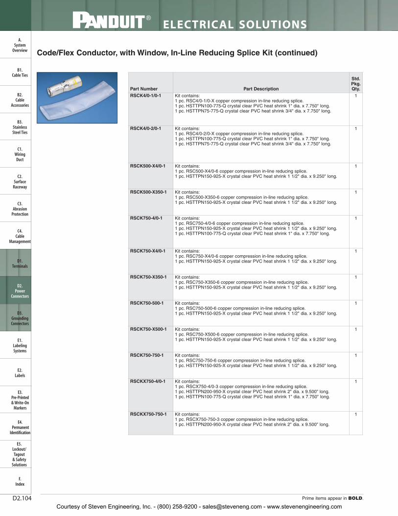
ELECTRICAL SOLUTIONS
Prime items appear in BOLD.D2.104
B2.Cable
Accessories
C1.Wiring
Duct
C3.Abrasion
Protection
C4.Cable
Management
D1.Terminals
D2.Power
Connectors
E1.LabelingSystems
E2.Labels
E3.Pre-Printed & Write-On
Markers
F.Index
B3.StainlessSteel Ties
C2.Surface
Raceway
E5.Lockout/Tagout
& SafetySolutions
B1.Cable Ties
A.System
Overview
D3.GroundingConnectors
E4.Permanent
Identification
Std.Pkg.Qty.Part DescriptionPart Number
RSCK4/0-1/0-1 Kit contains:1 pc. RSC4/0-1/0-X copper compression in-line reducing splice.1 pc. HSTTPN100-775-Q crystal clear PVC heat shrink 1" dia. x 7.750" long.1 pc. HSTTPN75-775-Q crystal clear PVC heat shrink 3/4" dia. x 7.750" long.
1
RSCK4/0-2/0-1 Kit contains:1 pc. RSC4/0-2/0-X copper compression in-line reducing splice.1 pc. HSTTPN100-775-Q crystal clear PVC heat shrink 1" dia. x 7.750" long.1 pc. HSTTPN75-775-Q crystal clear PVC heat shrink 3/4" dia. x 7.750" long.
1
RSCK500-X4/0-1 Kit contains:1 pc. RSC500-X4/0-6 copper compression in-line reducing splice.1 pc. HSTTPN150-925-X crystal clear PVC heat shrink 1 1/2" dia. x 9.250" long.
1
RSCK500-X350-1 Kit contains:1 pc. RSC500-X350-6 copper compression in-line reducing splice.1 pc. HSTTPN150-925-X crystal clear PVC heat shrink 1 1/2" dia. x 9.250" long.
1
RSCK750-4/0-1 Kit contains:1 pc. RSC750-4/0-6 copper compression in-line reducing splice.1 pc. HSTTPN150-925-X crystal clear PVC heat shrink 1 1/2" dia. x 9.250" long.1 pc. HSTTPN100-775-Q crystal clear PVC heat shrink 1" dia. x 7.750" long.
1
RSCK750-X4/0-1 Kit contains:1 pc. RSC750-X4/0-6 copper compression in-line reducing splice.1 pc. HSTTPN150-925-X crystal clear PVC heat shrink 1 1/2" dia. x 9.250" long.
1
RSCK750-X350-1 Kit contains:1 pc. RSC750-X350-6 copper compression in-line reducing splice.1 pc. HSTTPN150-925-X crystal clear PVC heat shrink 1 1/2" dia. x 9.250" long.
1
RSCK750-500-1 Kit contains:1 pc. RSC750-500-6 copper compression in-line reducing splice.1 pc. HSTTPN150-925-X crystal clear PVC heat shrink 1 1/2" dia. x 9.250" long.
1
RSCK750-X500-1 Kit contains:1 pc. RSC750-X500-6 copper compression in-line reducing splice.1 pc. HSTTPN150-925-X crystal clear PVC heat shrink 1 1/2" dia. x 9.250" long.
1
RSCK750-750-1 Kit contains:1 pc. RSC750-750-6 copper compression in-line reducing splice.1 pc. HSTTPN150-925-X crystal clear PVC heat shrink 1 1/2" dia. x 9.250" long.
1
RSCKX750-4/0-1 Kit contains:1 pc. RSCX750-4/0-3 copper compression in-line reducing splice.1 pc. HSTTPN200-950-X crystal clear PVC heat shrink 2" dia. x 9.500" long.1 pc. HSTTPN100-775-Q crystal clear PVC heat shrink 1" dia. x 7.750" long.
1
RSCKX750-750-1 Kit contains:1 pc. RSCX750-750-3 copper compression in-line reducing splice.1 pc. HSTTPN200-950-X crystal clear PVC heat shrink 2" dia. x 9.500" long.
1
Code/Flex Conductor, with Window, In-Line Reducing Splice Kit (continued)
Courtesy of Steven Engineering, Inc. - (800) 258-9200 - [email protected] - www.stevenengineering.com

For technical assistance in the U.S., call 866-405-6654 (outside the U.S., see inside back cover for directory)
ELECTRICAL SOLUTIONS
D2.105
B2.Cable
Accessories
C1.Wiring
Duct
C3.Abrasion
Protection
C4.Cable
Management
D1.Terminals
D2.Power
Connectors
E1.LabelingSystems
E2.Labels
E3.Pre-Printed & Write-On
Markers
F.Index
B3.StainlessSteel Ties
C2.Surface
Raceway
E5.Lockout/Tagout
& SafetySolutions
B1.Cable Ties
A.System
Overview
D3.GroundingConnectors
E4.Permanent
Identification
Code/Flex Conductor, with Window, In-Line Reducing Splice
‡See pages D3.76 – D3.81 for tool and die information.**Consult cable manufacturer for voltage stress relief instructions with applications greater than 2000 V.
• Low profile design provides minimum space requirements
• Manufactured from seamless, high conductivity copper tubing
• Color-coded barrels marked with Panduit and specified competitordie index numbers for proper crimp die selection
• Inspection windows in each barrel to visually assure fullconductor insertion
• Generous internally beveled wire entry for easy conductor insertion
• Tin-plated to inhibit corrosion
• UL Listed and CSA Certified to 35 KV** and temperature rated to90°C when crimped with Panduit and specified competitorcrimping tools and dies
• Also sold as a kit with crystal clear PVC heat shrink (see pagesD2.103, D2.104)
L
BFROM
BTO
For Use with Stranded Copper Code and Class I Flex Conductors
Type RSC
Part NumberCopper Conductor
Size
FigureDimensions
(In.)Panduit ColorCode
Panduit Die Index
No.‡
BurndyDie Index
No.‡
T&BDie Index
No.‡
WireStrip
Length(In.)
Std.Pkg.Qty.B L
RSC4-6-L Reduces From #4 – 3 AWG STR,#2 AWG SOL 1.052.54
Gray P29 8 29 1 1
Reduces To #6 AWG 1.38 Blue P24 7 24 1 5/16
RSC2-6-Q Reduces From #2 AWG 1.052.62
Brown P33 10 33 1 1
Reduces To #6 AWG 1.38 Blue P24 7 34 1 5/16
RSC2-4-Q Reduces From #2 AWG 1.052.50
Brown P33 10 33 1 1
Reduces To #4 – 3 AWG STR,#2 AWG SOL 1.38 Gray P29 8 29 1 5/16
RSC1/0-6-X Reduces From 1/0 AWG 1.052.81
Pink P42 12 42 1 1
Reduces To #6 AWG 1.38 Blue P24 7 24 1 5/16
RSC1/0-4-X Reduces From 1/0 AWG 1.052.70
Pink P42 12 42 1 1
Reduces To #4 – 3 AWG STR,#2 AWG SOL 1.38 Gray P29 8 29 1 5/16
RSC2/0-6-X Reduces From 2/0 AWG 1.132.99
Black P45 13 45 1 1/16 1
Reduces To #6 AWG 1.38 Blue P24 7 24 1 5/16
RSC2/0-4-X Reduces From 2/0 AWG 1.132.88
Black P45 13 45 1 1/16 1
Reduces To #4 – 3 AWG STR,#2 AWG SOL 1.38 Gray P29 8 29 1 5/16
RSC4/0-6-X Reduces From 4/0 AWG 1.133.24
Purple P54 15 54 1 1/16 1
Reduces To #6 AWG 1.38 Blue P24 7 24 1 5/16
RSC4/0-4-X Reduces From 4/0 AWG 1.133.12
Purple P54 15 54 1 1/16 1
Reduces To #4 – 3 AWG STR,#2 AWG SOL 1.38 Gray P29 8 29 1 5/16
RSC4/0-1/0-X Reduces From 4/0 AWG 1.163.13
Purple P54 15 54 1 1/16 1
Reduces To 1/0 AWG 1.63 Pink P42 12 42 1 9/16
RSC4/0-2/0-X Reduces From 4/0 AWG 1.162.90
Purple P54 15 54 1 1/16 1
Reduces To 2/0 AWG 1.50 Black P45 13 45 1 7/16
RSC500-X4/0-6 Reduces From 500 kcmil 1.943.97
Brown P87 20 87 1 7/8 1
Reduces To 4/0 Flex 1.50 Yellow P62 16 62 1 7/16
RSC500-X350-6 Reduces From 500 kcmil 1.944.38
Brown P87 20 87 1 7/8 1
Reduces To 350 Flex 1.94 Blue P76 19 76 1 7/8
Table continues on page D2.106
Courtesy of Steven Engineering, Inc. - (800) 258-9200 - [email protected] - www.stevenengineering.com

ELECTRICAL SOLUTIONS
Prime items appear in BOLD.D2.106
B2.Cable
Accessories
C1.Wiring
Duct
C3.Abrasion
Protection
C4.Cable
Management
D1.Terminals
D2.Power
Connectors
E1.LabelingSystems
E2.Labels
E3.Pre-Printed & Write-On
Markers
F.Index
B3.StainlessSteel Ties
C2.Surface
Raceway
E5.Lockout/Tagout
& SafetySolutions
B1.Cable Ties
A.System
Overview
D3.GroundingConnectors
E4.Permanent
Identification
Code/Flex Conductor, with Window, In-Line Reducing Splice (continued)
‡See pages D3.76 – D3.81 for tool and die information.**Consult cable manufacturer for voltage stress relief instructions with applications greater than 2000 V.
LB
Std.Pkg.Qty.
WireStrip
Length(In.)
T&B Die Index
No.‡
BurndyDie Index
No.‡
Panduit Die Index
No.‡
Panduit ColorCode
FigureDimensions
(In.)Copper ConductorSizePart Number
RSC750-4/0-6 Reduces From 750 kcmil 2.064.66
Black P106 24 106 2 1
Reduces To 4/0 AWG 1.50 Purple P54 15 54 1 5/8
RSC750-X4/0-6 Reduces From 750 kcmil 2.064.54
Black P106 24 106 2 1
Reduces To 4/0 Flex 1.50 Yellow P62 16 62 1 7/16
RSC750-X350-6 Reduces From 750 kcmil 2.064.45
Black P106 24 106 2 1
Reduces To 350 Flex 1.94 Blue P76 19 76 1 7/8
RSC750-500-6 Reduces From 750 kcmil 2.064.45
Black P106 24 106 2 1
Reduces To 500 kcmil 1.94 Brown P87 20 87 1 7/8
RSC750-X500-6 Reduces From 750 kcmil 2.064.63
Black P106 24 106 2 1
Reduces To 500 Flex 2.06 Pink P99 400 99 2
RSC750-750-6 Reduces From 750 kcmil 2.064.63
Black P106 24 106 2 1
Reduces To 750 kcmil 2.06 Black P106 24 106 2
RSCX750-4/0-3 Reduces From 750 Flex 2.065.04
Yellow P115 115 115 2 1
Reduces To 4/0 AWG 1.50 Purple P54 15 54 1 5/8
RSCX750-750-3 Reduces From 750 Flex 2.064.50
Yellow P115 115 115 2 1
Reduces To 750 kcmil 2.06 Black P106 24 106 2
Courtesy of Steven Engineering, Inc. - (800) 258-9200 - [email protected] - www.stevenengineering.com

For technical assistance in the U.S., call 866-405-6654 (outside the U.S., see inside back cover for directory)
ELECTRICAL SOLUTIONS
D2.107
B2.Cable
Accessories
C1.Wiring
Duct
C3.Abrasion
Protection
C4.Cable
Management
D1.Terminals
D2.Power
Connectors
E1.LabelingSystems
E2.Labels
E3.Pre-Printed & Write-On
Markers
F.Index
B3.StainlessSteel Ties
C2.Surface
Raceway
E5.Lockout/Tagout
& SafetySolutions
B1.Cable Ties
A.System
Overview
D3.GroundingConnectors
E4.Permanent
Identification
Metric Conductor, One-Hole, Standard Barrel with Window Lug
• Inspection window to visually assure full conductor insertion
• Tin-plated to inhibit corrosion
• UL Listed, UL Recognized, and CSA Certified to 35 KV** andtemperature rated to 90°C when crimped with Panduit tools and dies
• Product information marked on connector for selection and installation
• Rounded tongue convenient for use in tight spaces
• Internally beveled wire entry for fast and easy installation
N
M
INSPECTIONWINDOW
I
L
D
B
For Use with Class 2 Stranded Copper Conductors
Type LCMA
‡See page D3.83 for tool and die information.*UL Recognized only.**Consult cable manufacturer for voltage stress relief instructions with applications greater than 2000 V.
LCMA 150 – 10 – X150 = 150mm2 10 = 10mm 1 = 1 X = 10 C = 100
5 = 5 L = 50
Part Number System for Metric Lugs
Part Number System for Pan-Lug ™ Compression Metric Lugs
150 — —10 X
ConductorSize
Stud Hole Size
LCMA
Type
5 = #5
6 = 6mm
8 = 8mm
10 = 10mm
12 = 12mm
14 = 14mm
16 = 16mm
20 = 20mm
00 = Blank Tongue*
1 = 1
5 = 5
6 = 6
X = 10
Q = 25
L = 50
C = 100
Standard Package Size
B
INSPECTIONWINDOW
L
I
Part Number
Copper Conductor
SizeClass 2R
(mm²)
CurrentRating (Amps)
Stud HoleSize (mm)
Figure Dimensions (mm)
Panduit Die Index
No.‡
Std.Pkg.Qty.ØI B M N L ØD
LCMA6-5-C* 4 – 6 30 M5 3.8 10.0 7.8 6.2 27.5 5.5 P10 100LCMA6-6-C* 4 – 6 30 M6 3.8 10.8 7.8 6.2 27.5 6.6 P10 100LCMA6-8-C* 4 – 6 30 M8 3.8 13.0 8.0 8.0 30.5 9.0 P10 100
Table continues on page D2.108
Courtesy of Steven Engineering, Inc. - (800) 258-9200 - [email protected] - www.stevenengineering.com

ELECTRICAL SOLUTIONS
Prime items appear in BOLD.D2.108
‡See page D3.83 for tool and die information.*UL Recognized only.**Consult cable manufacturer for voltage stress relief instructions with applications greater than 2000 V.
Metric Conductor, One-Hole, Standard Barrel withWindow Lug (continued)
B2.Cable
Accessories
C1.Wiring
Duct
C3.Abrasion
Protection
C4.Cable
Management
D1.Terminals
D2.Power
Connectors
E1.LabelingSystems
E2.Labels
E3.Pre-Printed & Write-On
Markers
F.Index
B3.StainlessSteel Ties
C2.Surface
Raceway
E5.Lockout/Tagout
& SafetySolutions
B1.Cable Ties
A.System
Overview
D3.GroundingConnectors
E4.Permanent
Identification
Part Number
Copper Conductor
SizeClass 2R (mm²)
CurrentRating (Amps)
Stud HoleSize (mm)
Figure Dimensions (mm)
Panduit Die Index
No.‡
Std.Pkg.Qty.ØI B M N L ØD
LCMA10-5-C 10 — M5 4.5 11.0 9.8 6.0 30.8 5.5 P21 100LCMA10-6-C 10 — M6 4.5 11.0 9.8 6.0 30.8 6.6 P21 100LCMA10-8-C 10 — M8 4.5 13.0 8.5 8.0 30.8 9.0 P21 100LCMA10-10-C 10 — M10 4.4 14.5 8.5 8.0 30.8 11.0 P21 100LCMA16-5-C* 16 65 M5 5.5 13.0 10.3 6.5 34.5 5.5 P24 100LCMA16-6-C* 16 65 M6 5.5 13.0 10.3 6.5 34.5 6.6 P24 100LCMA16-8-C* 16 65 M8 5.5 13.0 10.3 6.5 34.5 9.0 P24 100LCMA16-10-C* 16 65 M10 5.5 15.0 10.2 8.0 36.7 11.0 P24 100LCMA25-6-C 25 — M6 6.9 14.0 10.0 8.0 37.0 6.6 P29 100LCMA25-8-C 25 — M8 6.9 15.5 10.0 8.0 37.0 9.0 P29 100LCMA25-10-C 25 — M10 6.9 15.5 10.0 8.0 37.0 11.0 P29 100LCMA35-6-C 35 — M6 8.2 15.5 12.3 8.5 42.0 6.6 P29 100LCMA35-8-C 35 — M8 8.2 15.5 12.3 8.5 42.0 9.0 P29 100LCMA35-10-C 35 — M10 8.2 15.5 12.3 8.5 42.0 11.0 P29 100LCMA35-12-C 35 — M12 8.2 21.5 14.5 11.5 48.0 14.0 P29 100LCMA50-6-L 50 — M6 9.8 18.0 11.5 10.0 46.5 6.6 P37 50LCMA50-8-L 50 — M8 9.8 18.0 11.5 10.0 46.5 9.0 P37 50LCMA50-10-L 50 — M10 9.8 18.0 11.5 10.0 46.5 11.0 P37 50LCMA50-12-L 50 — M12 9.8 23.0 14.0 11.0 50.0 14.0 P37 50LCMA70-6-L 70 — M6 11.5 20.8 14.5 11.5 53.5 6.6 P45 50LCMA70-8-L 70 — M8 11.5 20.8 14.5 11.5 53.5 9.0 P45 50LCMA70-10-L 70 — M10 11.5 20.8 14.5 11.5 53.5 11.0 P45 50LCMA70-12-L 70 — M12 11.5 20.8 14.5 11.5 53.5 14.0 P45 50LCMA95-8-L 95 — M8 13.5 24.5 15.0 13.5 60.5 9.0 P54 50LCMA95-10-L 95 — M10 13.5 24.5 15.0 13.5 60.5 11.0 P54 50LCMA95-12-L 95 — M12 13.5 24.5 15.0 13.5 60.5 14.0 P54 50LCMA95-16-L 95 — M16 13.5 24.5 15.0 13.5 60.5 18.0 P54 50LCMA120-8-L 120 — M8 15.2 27.5 15.5 14.5 65.0 9.0 P62 50LCMA120-10-L 120 — M10 15.2 27.5 15.5 14.5 65.0 11.0 P62 50LCMA120-12-L 120 — M12 15.2 27.5 15.5 14.5 65.0 14.0 P62 50LCMA120-16-L 120 — M16 15.2 27.5 15.5 14.5 65.0 18.0 P62 50LCMA150-8-X 150 — M8 16.5 30.5 18.0 16.5 70.5 9.0 P66 10LCMA150-10-X 150 — M10 16.5 30.5 18.0 16.5 70.5 11.0 P66 10LCMA150-12-X 150 — M12 16.5 30.5 18.0 16.5 70.5 14.0 P66 10LCMA150-16-X 150 — M16 16.5 30.5 18.0 16.5 70.5 18.0 P66 10LCMA150-20-X 150 — M20 16.5 30.5 22.0 16.5 74.0 22.0 P66 10LCMA185-10-X 185 — M10 18.6 33.5 16.5 17.5 72.5 11.0 P76 10LCMA185-12-X 185 — M12 18.6 33.5 16.5 17.5 72.5 14.0 P76 10LCMA185-16-X 185 — M16 18.6 33.5 16.5 17.5 72.5 18.0 P76 10LCMA185-20-X 185 — M20 18.6 33.5 21.0 17.5 77.0 22.0 P76 10LCMA240-10-X 240 — M10 20.8 37.5 21.0 19.5 86.5 11.0 P87 10LCMA240-12-X 240 — M12 20.8 37.5 21.0 19.5 86.5 14.0 P87 10LCMA240-16-X 240 — M16 20.8 37.5 21.0 19.5 86,5 18.0 P87 10LCMA240-20-X 240 — M20 20.8 37.5 21.0 19.5 86.5 22.0 P87 10LCMA300-10-5 300 — M10 23.5 42.5 22.0 20.0 94.5 11.0 P94 5LCMA300-12-5 300 — M12 23.5 42.5 22.0 20.0 94.5 14.0 P94 5LCMA300-16-5 300 — M16 23.5 42.5 22.0 20.0 94.5 18.0 P94 5LCMA300-20-5 300 — M20 23.5 42.5 22.0 20.0 94.5 22.0 P94 5LCMA400-12-5 400 — M12 27.0 49.5 26,5 23.5 107.0 14.0 P106 5LCMA400-16-5 400 — M16 27.0 49.5 26.5 23.5 107.0 18.0 P106 5LCMA400-20-5 400 — M20 27.0 49.5 26.5 23.5 107.0 22.0 P106 5LCMA500-12-1 500 — M12 31.0 57.5 28,5 25.5 120.0 14.0 P125 1LCMA500-16-1 500 — M16 31.0 57.5 28.5 25.5 120.0 18.0 P125 1LCMA500-20-1 500 — M20 31.0 57.5 28.5 25.5 120.0 22.0 P125 1LCMA500-00-1* 500 — Blank 31.0 57.5 — — 120.0 — P125 1LCMA630-16-1 630 — M16 34.5 63.0 28.5 27.5 131.0 18.0 P125 1LCMA630-20-1 630 — M20 34.5 63.0 28.5 27.5 131.0 22.0 P125 1LCMA630-00-1* 630 — Blank 34.5 63.0 — — 131.0 — P125 1
Courtesy of Steven Engineering, Inc. - (800) 258-9200 - [email protected] - www.stevenengineering.com

For technical assistance in the U.S., call 866-405-6654 (outside the U.S., see inside back cover for directory)
ELECTRICAL SOLUTIONS
D2.109
B2.Cable
Accessories
C1.Wiring
Duct
C3.Abrasion
Protection
C4.Cable
Management
D1.Terminals
D2.Power
Connectors
E1.LabelingSystems
E2.Labels
E3.Pre-Printed & Write-On
Markers
F.Index
B3.StainlessSteel Ties
C2.Surface
Raceway
E5.Lockout/Tagout
& SafetySolutions
B1.Cable Ties
A.System
Overview
D3.GroundingConnectors
E4.Permanent
Identification
Metric Conductor, Two-Hole, Standard Barrel with Window Lug
• Inspection window to visually assure full conductor insertion
• Tin-plated to inhibit corrosion
• UL Listed, UL Recognized, and CSA Certified to 35 KV** andtemperature rated to 90°C when crimped with Panduit tools and dies
• Product information marked on connector for selection and installation
• Internally beveled wire entry for fast and easy installation
For Use with Class 2 Stranded Copper Conductors
Type LCMD
B
I
L
INSPECTIONWINDOW
‡See page D3.83 for tool and die information.*UL Recognized only.**Consult cable manufacturer for voltage stress relief instructions with applications greater than 2000 V.
D
B
STUD HOLESPACINGN M
INSPECTIONWINDOW
I
L
INSPECTIONWINDOW
B
STUD HOLESPACINGN M
D
L
I
PartNumber
Copper Conductor
Size Class 2R (mm²)
Current Rating (Amps)
StudHole Size
(mm)
Stud Hole
Spacing (mm)
Figure Dimensions (mm)Panduit
Die Index No.‡
Std.Pkg.Qty.ØI B M N L ØD
LCMD6-5CD-Q* 4 – 6 30 M5 22.0 – 25.0 3.8 10.0 7.8 6.2 52.5 5.5 P10 25LCMD10-6CD-Q 10 — M6 22.0 – 25.0 4.5 11.0 9.8 6.0 55.8 6.6 P21 25LCMD10-8-Q 10 — M8 44.5 4.5 13.0 8.5 8.0 75.3 9.0 P21 25LCMD10-00-Q* 10 — Blank — 4.4 14.5 — — 75.3 — P21 25LCMD16-6CD-Q* 16 65 M6 22.0 – 25.0 5.5 13.0 10.3 6.5 59.5 6.6 P24 25LCMD16-8-Q* 16 65 M8 44.5 5.5 13.0 10.3 6.5 79.0 9.0 P24 25LCMD16-00-Q* 16 65 Blank — 5.5 15.0 — — 81.2 — P24 25LCMD25-8CD-Q* 25 — M8 22.0 – 25.0 6.9 15.5 10.0 8.0 62.0 9.0 P29 25LCMD25-8-Q 25 — M8 44.5 6.9 15.5 10.0 8.0 81.5 9.0 P29 25LCMD25-10-Q 25 — M10 44.5 6.9 15.5 10.0 8.0 81.5 11.0 P29 25LCMD25-12-Q 25 — M12 44.5 7.1 20.0 14.5 11.5 89.5 14.0 P29 25LCMD25-00-Q* 25 — Blank — 7.1 20.0 — — 89.5 — P29 25LCMD35-8CD-Q 35 — M8 22.0 – 25.0 8.2 15.5 12.3 8.5 67.0 9.0 P29 25LCMD35-10-Q 35 — M10 44.5 8.2 15.5 12.3 8.5 86.5 11.0 P29 25LCMD35-12-Q 35 — M12 44.5 8.2 21.5 14.5 11.5 92.5 14.0 P29 25LCMD35-00-Q* 35 — Blank — 8.2 21.5 — — 92.5 — P29 25LCMD50-10CD-X 50 — M10 22.0 – 25.0 9.8 18.0 11.5 10.0 71.5 11.0 P37 10LCMD50-10-X 50 — M10 44.5 9.8 18.0 11.5 10.0 91.0 11.0 P37 10LCMD50-12-X 50 — M12 44.5 9.8 23.0 14.0 11.0 94.5 14.0 P37 10LCMD50-00-X* 50 — Blank — 9.8 23.0 — — 94.5 — P37 10LCMD70-10CD-X 70 — M10 22.0 – 25.0 11.5 20.5 14.5 11.0 78.5 11.0 P45 10LCMD70-10-X 70 — M10 44.5 11.5 20.8 14.5 11.5 98.0 11.0 P45 10LCMD70-12-X 70 — M12 44.5 11.5 20.8 14.5 11.5 98.0 14.0 P45 10LCMD70-00-X* 70 — Blank — 11.5 20.8 — — 98.0 — P45 10LCMD95-10CD-X 95 — M10 22.0 – 25.0 13.5 24.5 15.0 13.0 85.5 11.0 P54 10LCMD95-12-X 95 — M12 44.5 13.5 24.5 15.0 13.5 105.0 14.0 P54 10LCMD95-14-X 95 — M14 44.5 13.5 24.5 15.0 13.5 105.0 16.0 P54 10LCMD95-00-X* 95 — Blank — 13.5 24.5 — — 105.0 — P54 10
Table continues on page D2.110
Courtesy of Steven Engineering, Inc. - (800) 258-9200 - [email protected] - www.stevenengineering.com

ELECTRICAL SOLUTIONS
Prime items appear in BOLD.D2.110
B2.Cable
Accessories
C1.Wiring
Duct
C3.Abrasion
Protection
C4.Cable
Management
D1.Terminals
D2.Power
Connectors
E1.LabelingSystems
E2.Labels
E3.Pre-Printed & Write-On
Markers
F.Index
B3.StainlessSteel Ties
C2.Surface
Raceway
E5.Lockout/Tagout
& SafetySolutions
B1.Cable Ties
A.System
Overview
D3.GroundingConnectors
E4.Permanent
Identification
‡See page D3.83 for tool and die information.*UL Recognized only.**Consult cable manufacturer for voltage stress relief instructions with applications greater than 2000 V.
Metric Conductor, Two-Hole, Standard Barrel with Window Lug (continued)
ØDLNMBØI
Std.Pkg.Qty.
Panduit Die Index
No.‡
Figure Dimensions (mm)Stud Hole
Spacing (mm)
StudHole Size
(mm)
Current Rating (Amps)
Copper Conductor
Size Class 2R (mm²)
PartNumberLCMD120-10CD-X 120 — M10 22.0 – 25.0 15.2 27.5 15.5 14.0 90.0 11.0 P62 10LCMD120-12-X 120 — M12 44.5 15.2 27.5 15.5 14.5 109.5 14.0 P62 10LCMD120-14-X 120 — M14 44.5 15.2 27.5 15.5 14.5 109.5 16.0 P62 10LCMD120-00-X* 120 — Blank — 15.2 27.5 — — 109.5 — P62 10LCMD150-10CD-X 150 — M10 22.0 – 25.0 16.5 30.5 18.0 16.0 95.5 11.0 P66 10LCMD150-12-X 150 — M12 44.5 16.5 30.5 18.0 16.5 115.0 14.0 P66 10LCMD150-14-X 150 — M14 44.5 16.5 30.5 22.0 16.5 118.5 16.0 P66 10LCMD150-00-X* 150 — Blank — 16.5 30.5 — — 118.5 — P66 10LCMD185-10CD-X 185 — M10 22.0 – 25.0 18.6 33.5 16.5 17.0 97.5 11.0 P76 10LCMD185-12-X 185 — M12 44.5 18.6 33.5 16.5 17.5 117.0 14.0 P76 10LCMD185-14-X 185 — M14 44.5 18.6 33.5 21.0 17.5 121.5 16.0 P76 10LCMD185-00-X* 185 — Blank — 18.6 33.5 — — 121.5 — P76 10LCMD240-10CD-5 240 — M10 22.0 – 25.0 20.8 37.5 21.0 19.0 111.5 11.0 P87 5LCMD240-12-5 240 — M12 44.5 20.8 37.5 21.0 19.5 131.0 14.0 P87 5LCMD240-14-5 240 — M14 44.5 20.8 37.5 21.0 19.5 131.0 16.0 P87 5LCMD240-00-5* 240 — Blank — 20.8 37.5 — — 131.0 — P87 5LCMD300-12-5 300 — M12 44.5 23.5 42.5 22.0 20.0 139.0 14.0 P94 5LCMD300-14-5 300 — M14 44.5 23.5 42.5 22.0 20.0 139.0 16.0 P94 5LCMD300-00-5* 300 — Blank — 23.5 42.5 — — 139.0 — P94 5LCMD400-12-5 400 — M12 44.5 27.0 49.5 26.5 23.5 151.5 14.0 P106 5LCMD400-14-5 400 — M14 44.5 27.0 49.5 26.5 23.5 151.5 16.0 P106 5LCMD400-16-5 400 — M16 44.5 27.0 49.5 26.5 23.5 151.5 18.0 P106 5LCMD400-00-5* 400 — Blank — 27.0 49.5 — — 151.5 — P106 5LCMD500-12-1 500 — M12 44.5 31.0 57.5 28.5 25.5 164.5 14.0 P125 1LCMD500-14-1 500 — M14 44.5 31.0 57.5 28.5 25.5 164.5 16.0 P125 1LCMD500-16-1 500 — M16 44.5 31.0 57.5 28.5 25.5 164.5 18.0 P125 1LCMD500-00-1* 500 — Blank — 31.0 57.5 — — 164.5 — P125 1LCMD630-12-1 630 — M12 44.5 34.5 63.0 28.5 27.5 175.5 14.0 P125 1LCMD630-14-1 630 — M14 44.5 34.5 63.0 28.5 27.5 175.5 16.0 P125 1LCMD630-16-1 630 — M16 44.5 34.5 63.0 28.5 27.5 175.5 18.0 P125 1LCMD630-00-1* 630 — Blank — 34.5 63.0 — — 175.5 — P125 1
Courtesy of Steven Engineering, Inc. - (800) 258-9200 - [email protected] - www.stevenengineering.com

For technical assistance in the U.S., call 866-405-6654 (outside the U.S., see inside back cover for directory)
ELECTRICAL SOLUTIONS
D2.111
B2.Cable
Accessories
C1.Wiring
Duct
C3.Abrasion
Protection
C4.Cable
Management
D1.Terminals
D2.Power
Connectors
E1.LabelingSystems
E2.Labels
E3.Pre-Printed & Write-On
Markers
F.Index
B3.StainlessSteel Ties
C2.Surface
Raceway
E5.Lockout/Tagout
& SafetySolutions
B1.Cable Ties
A.System
Overview
D3.GroundingConnectors
E4.Permanent
Identification
Metric Conductor, Standard Barrel, Butt Splice
‡See page D3.83 for tool and die information.*UL Recognized only.**Consult cable manufacturer for voltage stress relief instructions with applications greater than 2000 V.
• Tin-plated to inhibit corrosion
• UL Listed, UL Recognized, and CSA Certified to 35 KV** andtemperature rated to 90°C when crimped with Panduit toolsand dies
• Product information marked on connector for selection and installation
• Internally beveled wire entry for fast and easy installation
L
I
For Use with Class 2 Stranded Copper Conductors
Type SCMS
PartNumber
Copper Conductor
Size Class 2R (mm²)
Current Rating (Amps)
Figure Dimensions (mm) Panduit Die Index
No.‡
Std.Pkg.Qty.ØI L
SCMS10-C* 10 50 4.5 30.0 P21 100SCMS16-C* 16 65 5.5 35.0 P24 100SCMS25-L 25 — 6.9 36.0 P29 50SCMS35-L 35 — 8.2 36.0 P29 50SCMS50-L 50 — 9.8 49.0 P37 50SCMS70-L 70 — 11.5 52.0 P45 50SCMS95-Q 95 — 13.5 54.0 P54 25SCMS120-Q 120 — 15.2 57.0 P62 25SCMS150-X 150 — 16.5 57.0 P66 10SCMS185-X 185 — 18.6 61.0 P76 10SCMS240-X 240 — 20.8 72.0 P87 10SCMS300-5 300 — 23.5 75.0 P94 5SCMS400-5 400 — 27.0 95.0 P106 5SCMS500-6 500 — 31.0 96.0 P125 6SCMS630-6 630 — 34.5 131.0 P125 6
Courtesy of Steven Engineering, Inc. - (800) 258-9200 - [email protected] - www.stevenengineering.com

ELECTRICAL SOLUTIONS
Prime items appear in BOLD.D2.112
B2.Cable
Accessories
C1.Wiring
Duct
C3.Abrasion
Protection
C4.Cable
Management
D1.Terminals
D2.Power
Connectors
E1.LabelingSystems
E2.Labels
E3.Pre-Printed & Write-On
Markers
F.Index
B3.StainlessSteel Ties
C2.Surface
Raceway
E5.Lockout/Tagout
& SafetySolutions
B1.Cable Ties
A.System
Overview
D3.GroundingConnectors
E4.Permanent
Identification
Code Conductor, One-Hole, Aluminum Lug
‡See pages D3.84, D3.85 for tool and die information.**Consult cable manufacturer for voltage stress relief instructions with applications greater than 2000 V.See page D2.118 for Panduit joint compounds recommended for pad to pad and conductor connections.
• Manufactured from high conductivity thick wall wrought aluminum
• Factory pre-filled with joint compound and sealed with easy pull-out end plug to inhibit corrosion
• Color-coded end plug and Panduit and specified competitor dieindex numbers marked on barrel for proper crimp die selection
• Enclosed barrel prevents corrosive material from entering barrelwhen used in harsh environments
• Tin-plated to inhibit corrosion
• UL Listed and CSA Certified to 35 KV** and temperature rated to 90°C when crimped with Panduit and specified competitorcrimping tools and dies
W
T
B
L
For Use with Stranded Aluminum or Copper Code Conductors
Type LAA
Part Number
Aluminum orCopper Conductor
Size
Stud HoleSize (In.)
Figure Dimensions (In.)
PanduitColorCode
PanduitDie Index
No.‡
BurndyDie Index
No.‡
T&B Die
Index No.‡
Wire StripLength
(In.)
Std.Pkg.Qty.W B T L
LAA6-14-X#6 AWG
1/4 0.55 0.86 0.11 2.20 Gray P29 346 29 1 10
LAA6-56-X 5/16 0.55 1.00 0.11 2.20 Gray P29 346 29 1 10
LAA4-14-X
#4 AWG
1/4 0.66 1.05 0.19 2.05 Green P37 375 37 1 1/16 10
LAA4-56-X 5/16 0.69 1.08 0.16 2.23 Green P37 375 37 1 1/16 10
LAA4-38-X 3/8 0.69 0.92 0.16 2.33 Green P37 375 37 1 1/16 10
LAA2-14-X
#2 AWG
1/4 0.75 0.98 0.17 2.63 Pink P42 348 42 1 10
LAA2-56-X 5/16 0.75 0.98 0.17 2.63 Pink P42 348 42 1 10
LAA2-38-X 3/8 0.75 0.98 0.17 2.63 Pink P42 348 42 1 10
LAA1-14-X
#1 AWG
1/4 0.75 0.98 0.17 2.63 Gold P45 471 45 1 10
LAA1-56-X 5/16 0.75 0.98 0.17 2.63 Gold P45 471 45 1 10
LAA1-38-X 3/8 0.75 0.98 0.17 2.63 Gold P45 471 45 1 10
LAA1/0-56-X
1/0 AWG
5/16 0.88 1.30 0.25 3.23 Tan P50 296 50 1 9/16 10
LAA1/0-38-X 3/8 0.88 1.30 0.25 3.23 Tan P50 296 50 1 9/16 10
LAA1/0-12-X 1/2 0.88 1.30 0.25 3.23 Tan P50 296 50 1 9/16 10
LAA2/0-38-52/0 AWG
3/8 0.95 1.31 0.23 3.19 Olive P54 297 54 1 9/16 5
LAA2/0-12-5 1/2 0.95 1.30 0.23 3.19 Olive P54 297 54 1 9/16 5
LAA3/0-38-53/0 AWG
3/8 1.07 1.50 0.25 3.44 Ruby P60 467 60 1 9/16 5
LAA3/0-12-5 1/2 1.07 1.50 0.25 3.44 Ruby P60 467 60 1 9/16 5
LAA4/0-38-54/0 AWG
3/8 1.19 1.44 0.32 3.56 White P66 298 66 1 3/4 5
LAA4/0-12-5 1/2 1.19 1.44 0.32 3.56 White P66 298 66 1 3/4 5
LAA250-38-5250 kcmil
3/8 1.24 1.56 0.30 3.63 Red P71 324 71 1 9/16 5
LAA250-12-5 1/2 1.24 1.56 0.30 3.63 Red P71 324 71 1 9/16 5
LAA300-38-2300 kcmil
3/8 1.38 2.25 0.34 4.05 Blue P76 470 76 2 5/16 2
LAA300-12-2 1/2 1.38 2.25 0.34 4.05 Blue P76 470 76 2 5/16 2
LAA350-12-2 350 kcmil 1/2 1.50 2.25 0.38 4.30 Brown P87 299 87 2 5/16 2
LAA400-58-2 400 kcmil 5/8 1.61 2.50 0.41 4.92 Green P94 472 94 2 9/16 2
LAA500-12-2500 kcmil
1/2 1.75 3.00 0.44 5.56 Pink P99 300 99 3 1/16 2
LAA500-58-2 5/8 1.75 3.00 0.44 5.56 Pink P99 300 99 3 1/16 2
LAA750-58-1 750 kcmil 5/8 1.75 3.38 0.53 6.55 Red P125 301 115 3 7/16 1
LAA1000-58-1 1000 kcmil 5/8 2.56 4.50 0.61 7.38 Brown P161 302 161 4 3/4 1
Courtesy of Steven Engineering, Inc. - (800) 258-9200 - [email protected] - www.stevenengineering.com

For technical assistance in the U.S., call 866-405-6654 (outside the U.S., see inside back cover for directory)
ELECTRICAL SOLUTIONS
D2.113
B2.Cable
Accessories
C1.Wiring
Duct
C3.Abrasion
Protection
C4.Cable
Management
D1.Terminals
D2.Power
Connectors
E1.LabelingSystems
E2.Labels
E3.Pre-Printed & Write-On
Markers
F.Index
B3.StainlessSteel Ties
C2.Surface
Raceway
E5.Lockout/Tagout
& SafetySolutions
B1.Cable Ties
A.System
Overview
D3.GroundingConnectors
E4.Permanent
Identification
Code Conductor, Two-Hole, Aluminum Lug
‡See pages D3.84, D3.85 for tool and die information.**Consult cable manufacturer for voltage stress relief instructions with applications greater than 2000 V.See page D2.118 for Panduit joint compounds recommended for pad to pad and conductor connections.◆NEMA hole sizes and spacing.
• Manufactured from high conductivity thick wall wrought aluminum
• Factory pre-filled with joint compound and sealed with easy pull-out end plug to inhibit corrosion
• Color-coded end plug and Panduit and specified competitor die index numbers marked on barrel for proper crimp die selection
• Enclosed barrel prevents corrosive material from entering barrelwhen used in harsh environments
• Tin-plated to inhibit corrosion
• UL Listed and CSA Certified to 35 KV** and temperature rated to 90°C when crimped with Panduit and specified competitorcrimping tools and dies
• Available with NEMA hole sizes and spacing
W
HOLESPACING
L
T
B
For Use with Stranded Aluminum or Copper Code Conductors
Type LAB
Part Number
Aluminumor Copper
Conductor Size
Stud HoleSize(In.)
Stud HoleSpacing
(In.)
Figure Dimensions (In.)
PanduitColorCode
PanduitDie Index
No.‡
BurndyDie Index
No.‡
T&BDie Index
No.‡
Wire StripLength
(In.)
Std.Pkg.Qty.W B T L
LAB1/0-38-X 1/0 AWG 3/8 1.75 0.88 1.55 0.25 5.33 Tan P50 296 50 1 9/16 10◆ LAB2/0-12-5 2/0 AWG 1/2 1.75 0.94 1.55 0.25 5.55 Olive P54 297 54 1 9/16 5
◆ LAB3/0-12-5 3/0 AWG 1/2 1.75 1.03 1.55 0.27 5.55 Ruby P60 467 60 1 9/16 5◆ LAB4/0-12-5 4/0 AWG 1/2 1.75 1.19 1.80 0.31 5.98 White P66 298 66 1 3/4 5◆ LAB250-12-5 250 kcmil 1/2 1.75 1.25 1.80 0.31 6.05 Red P71 324 71 1 3/4 5◆ LAB300-12-2 300 kcmil 1/2 1.75 1.36 2.30 0.34 6.61 Blue P76 470 76 2 5/16 2◆ LAB350-12-2 350 kcmil 1/2 1.75 1.50 2.30 0.38 6.61 Brown P87 299 87 2 5/16 2◆ LAB400-12-2 400 kcmil 1/2 1.75 1.66 2.55 0.38 6.92 Green P94 472 94 2 9/16 2◆ LAB500-12-2 500 kcmil 1/2 1.75 1.72 3.05 0.44 7.36 Pink P99 300 99 3 1/16 2◆ LAB600-12-2 600 kcmil 1/2 1.75 1.72 3.05 0.50 7.55 Black P106 473 106 3 1/16 2◆ LAB750-12-1 750 kcmil 1/2 1.75 1.72 3.42 0.56 7.31 Red P125 301 115 3 7/16 1◆ LAB800-12-1 800 kcmil 1/2 1.75 1.72 3.42 0.59 8.30 Gray P140 474 125 3 7/16 1◆ LAB1000-12-1 1000 kcmil 1/2 1.75 2.56 4.67 0.63 9.67 Brown P161 302 161 4 3/4 1
Courtesy of Steven Engineering, Inc. - (800) 258-9200 - [email protected] - www.stevenengineering.com

ELECTRICAL SOLUTIONS
Prime items appear in BOLD.D2.114
B2.Cable
Accessories
C1.Wiring
Duct
C3.Abrasion
Protection
C4.Cable
Management
D1.Terminals
D2.Power
Connectors
E1.LabelingSystems
E2.Labels
E3.Pre-Printed & Write-On
Markers
F.Index
B3.StainlessSteel Ties
C2.Surface
Raceway
E5.Lockout/Tagout
& SafetySolutions
B1.Cable Ties
A.System
Overview
D3.GroundingConnectors
E4.Permanent
Identification
Belleville Compression Washers
Part NumberStud Hole Size
(In.)
Figure Dimensions (In.)
Std.Pkg.Qty.D H T
CW-14-L 1/4 .68 .09 .05 50
CW-56-L 5/16 .81 .08 .06 50
CW-38-L 3/8 .93 .10 .07 50
CW-12-Q 1/2 1.18 .12 .09 25
CW-58-Q 5/8 1.49 .15 .12 25
• Conical spring washer for use when assembling aluminumconnectors to copper and/or steel pads, compensates fordiffering rates of thermal expansion to keep hardware assemblyfrom loosening
• For assembly information, see page D2.158
• Made from hardened steel to provide high strength
• Cadmium-plated to inhibit corrosion
D
T
H
Type CW
Courtesy of Steven Engineering, Inc. - (800) 258-9200 - [email protected] - www.stevenengineering.com

For technical assistance in the U.S., call 866-405-6654 (outside the U.S., see inside back cover for directory)
ELECTRICAL SOLUTIONS
D2.115
B2.Cable
Accessories
C1.Wiring
Duct
C3.Abrasion
Protection
C4.Cable
Management
D1.Terminals
D2.Power
Connectors
E1.LabelingSystems
E2.Labels
E3.Pre-Printed & Write-On
Markers
F.Index
B3.StainlessSteel Ties
C2.Surface
Raceway
E5.Lockout/Tagout
& SafetySolutions
B1.Cable Ties
A.System
Overview
D3.GroundingConnectors
E4.Permanent
Identification
Code Conductor, Aluminum Splice
‡See pages D3.84, D3.85 for tool and die information.**Consult cable manufacturer for voltage stress relief instructions with applications greater than 2000 V.See page D2.118 for Panduit joint compounds recommended for pad to pad and conductor connections.
• Manufactured from high conductivity thick wall wrought aluminum
• Factory pre-filled with joint compound and sealed with easy pull-out end plug to inhibit corrosion
• Color-coded end plugs and Panduit and specified competitor dieindex numbers marked on barrel for proper crimp die selection
• Tin-plated to inhibit corrosion
• Internal solid center prevents over-insertion of conductor
• UL Listed and CSA Certified to 35 KV** and temperature rated to 90°C when crimped with Panduit and specified competitorcrimping tools and dies
L
O.D.
For Use with Stranded Aluminum-to-Aluminum or Copper-to-Copper Conductors
Type SA
Part Number
Aluminum orCopper Conductor
Size
Figure Dimensions(In.)
PanduitColorCode
PanduitDie Index
No.‡
BurndyDie Index
No.‡
T&BDie Index
No.‡
Wire StripLength
(In.)
Std.Pkg.Qty.Barrel O.D. L
SA6-X #6 AWG 0.34 1.62 Gray P29 346 29 3/4 10
SA4-X #4 AWG 0.48 2.13 Green P37 375 37 7/8 10
SA2-X #2 AWG 0.53 2.00 Pink P42 348 45 7/16 10
SA1-X #1 AWG 0.53 2.00 Gold P45 471 45 7/16 10
SA1/0-X 1/0 AWG 0.64 2.12 Tan P50 296 50 1 10
SA2/0-5 2/0 AWG 0.69 2.31 Olive P54 297 54 1 1/8 5
SA3/0-5 3/0 AWG 0.76 2.62 Ruby P60 467 60 1 1/4 5
SA4/0-5 4/0 AWG 0.88 2.75 White P66 298 66 1 5/16 5
SA250-5 250 kcmil 0.91 2.94 Red P71 324 71 1 7/16 5
SA300-2 300 kcmil 1.01 3.12 Blue P76 470 76 1 1/2 2
SA350-2 350 kcmil 1.12 3.37 Brown P87 299 87 1 5/8 2
SA400-2 400 kcmil 1.19 3.75 Green P94 472 94 1 13/16 2
SA500-2 500 kcmil 1.32 3.87 Pink P99 300 99 1 7/8 2
SA600-2 600 kcmil 1.44 4.12 Black P106 473 106 2 2
SA750-1 750 kcmil 1.60 4.62 Red P125 301 115 2 1/4 1
SA800-1 800 kcmil 1.66 4.75 Gray P140 474 125 2 5/16 1
SA1000-1 1000 kcmil 1.84 5.25 Brown P161 302 161 2 9/16 1
Courtesy of Steven Engineering, Inc. - (800) 258-9200 - [email protected] - www.stevenengineering.com

ELECTRICAL SOLUTIONS
Prime items appear in BOLD.D2.116
B2.Cable
Accessories
C1.Wiring
Duct
C3.Abrasion
Protection
C4.Cable
Management
D1.Terminals
D2.Power
Connectors
E1.LabelingSystems
E2.Labels
E3.Pre-Printed & Write-On
Markers
F.Index
B3.StainlessSteel Ties
C2.Surface
Raceway
E5.Lockout/Tagout
& SafetySolutions
B1.Cable Ties
A.System
Overview
D3.GroundingConnectors
E4.Permanent
Identification
Code Conductor, Aluminum, Reducing Splice
‡See pages D3.86 – D3.87 for tool and die information.**Consult cable manufacturer for voltage stress relief instructions with applications greater than 2000 V.See pages D2.118 for Panduit joint compounds recommended for pad to pad and conductor connections.
• Dual rated for use with aluminum or copper conductors
• Factory pre-filled with joint compound and sealed with easy pull-out end plug to inhibit corrosion
• Color-coded end plug and Panduit and specified competitor dieindex numbers marked on barrel for proper crimp die selection
• Tin-plated to inhibit corrosion
• For use up to 35 KV** and temperature rated 90°C when crimpedwith Panduit and specified competitor crimping tools and dies
O.D.
L
For Reducing Stranded Aluminum-to-Aluminum or Aluminum-to-Copper Conductors
Type SAR
Part Number
AluminumConductorSize From
Aluminum orCopper Conductor
Size To
Figure Dimensions(In.)
PanduitColorCode
PanduitDie Index
No.‡
BurndyDie Index
No.‡
T&BDie Index
No.‡
Wire StripLength
(In.)
Std.Pkg.Qty.Barrel O.D. L
SAR2-4-X #2 AWG #4 AWG 0.64 4.25 Tan P50 296 50 2 1/16 10
SAR1/0-2-X 1/0 AWG #2 AWG 0.64 4.25 Tan P50 296 50 2 1/16 10
SAR3/0-1/0-5 3/0 AWG 1/0 AWG 0.91 4.98 Red P71 324 71 2 5/16 5
SAR4/0-2/0-5 4/0 AWG 2/0 AWG 0.91 5.24 Red P71 324 71 2 3/16 5
SAR350-4/0-2 350 kcmil 4/0 AWG 1.12 6.63 Brown P87 299 87 3 3/16 2
SAR500-350-2 500 kcmil 350 kcmil 1.32 8.60 Pink P99 300 99 4 1/4 2
SAR600-500-2 600 kcmil 500 kcmil 1.49 9.25 Black P106 473 106 4 2
SAR750-600-2 750 kcmil 600 kcmil 1.60 9.88 Red P125 301 115 4 7/16 2
Courtesy of Steven Engineering, Inc. - (800) 258-9200 - [email protected] - www.stevenengineering.com

For technical assistance in the U.S., call 866-405-6654 (outside the U.S., see inside back cover for directory)
ELECTRICAL SOLUTIONS
D2.117
B2.Cable
Accessories
C1.Wiring
Duct
C3.Abrasion
Protection
C4.Cable
Management
D1.Terminals
D2.Power
Connectors
E1.LabelingSystems
E2.Labels
E3.Pre-Printed & Write-On
Markers
F.Index
B3.StainlessSteel Ties
C2.Surface
Raceway
E5.Lockout/Tagout
& SafetySolutions
B1.Cable Ties
A.System
Overview
D3.GroundingConnectors
E4.Permanent
Identification
Code Conductor, Aluminum, Bi-Metallic Pin Connector
‡See pages D3.88 – D3.89 for tool and die information.See pages D2.118 for Panduit joint compounds recommended for pad to pad and conductor connections.
• Factory pre-filled with joint compound and sealed with easypull-out end plug to inhibit corrosion
• Panduit die index number and color code embossed on barrelfor proper crimp die selection
• Insulating rubber sleeve included to insulate aluminum barrelfrom contact with copper connector when attached to pin
• Tin-plated to inhibit corrosion
• UL Listed per UL 486B; temperature rated 90°C and for use upto 600 V when crimped with Panduit and specified competitorcrimping tools and dies
L
P
COPPERPIGTAILCONDUCTOR
Provides Copper Pigtail for Connecting Aluminum Conductors to a Copper or Aluminum/Copper Rated Mechanical Lug
Type BPC
Part Number
AluminumConductor
SizeCopper Pigtail
Size
Figure Dimensions (In.)
PanduitColorCode
PanduitDie Index
No.‡
BurndyDie Index
No.‡
T&BDie Index
No.‡
Wire StripLength
(In.)
Std.Pkg.Qty.L P
BPC6-L #6 AWG #8 AWG 2.45 0.88 Tan P50 296 50 1 1/16 50
BPC4-L #4 AWG #6 AWG 2.45 0.88 Tan P50 296 50 1 1/16 50
BPC2-L #2 AWG #4 AWG 2.45 0.88 Tan P50 296 50 1 1/16 50
BPC1-X #1 AWG #3 AWG 2.58 1.00 Tan P50 296 50 1 1/16 10
BPC1/0-X 1/0 AWG #2 AWG 3.33 1.25 Red P71 298 76 1 5/16 10
BPC2/0-X 2/0 AWG #1 AWG 3.33 1.25 Red P71 298 76 1 5/16 10
BPC3/0-X 3/0 AWG 1/0 AWG 3.46 1.38 Red P71 298 76 1 5/16 10
BPC4/0-X 4/0 AWG 2/0 AWG 3.46 1.38 Red P71 298 76 1 5/16 10
BPC250-X 250 kcmil 3/0 AWG 3.71 1.50 Green P94 299 99, 87 1 7/16 10
BPC300-X 300 kcmil 4/0 AWG 4.10 1.63 Green P94 299 99, 87 1 7/16 10
BPC350-X 350 kcmil 4/0 AWG 4.10 1.63 Green P94 299 99, 87 1 7/16 10
BPC400-X 400 kcmil 250 kcmil 4.35 1.88 Black P106 300 106 1 7/16 10
BPC500-X 500 kcmil 350 kcmil 4.35 1.88 Black P106 300 106 1 7/16 10
BPC600-6 600 kcmil 350 kcmil 4.77 1.88 Red P125 936 115 1 15/16 6
BPC750-6 750 kcmil 500 kcmil 4.90 2.00 Red P125 936 115 1 15/16 6
Courtesy of Steven Engineering, Inc. - (800) 258-9200 - [email protected] - www.stevenengineering.com

ELECTRICAL SOLUTIONS
Prime items appear in BOLD.D2.118
B2.Cable
Accessories
C1.Wiring
Duct
C3.Abrasion
Protection
C4.Cable
Management
D1.Terminals
D2.Power
Connectors
E1.LabelingSystems
E2.Labels
E3.Pre-Printed & Write-On
Markers
F.Index
B3.StainlessSteel Ties
C2.Surface
Raceway
E5.Lockout/Tagout
& SafetySolutions
B1.Cable Ties
A.System
Overview
D3.GroundingConnectors
E4.Permanent
Identification
Joint Compounds
• Oxide inhibitor for compression conductor connections lowerselectrical resistance of compression joint while sealing out air and moisture to prevent the formation of surface oxides
• Wide operating temperature range; can be used in a wide range of electrical and environmental conditions
• Packaged in convenient dispenser bottles
Type CMP
Part Number Part Description
Std.Pkg.Qty.
CMP-100-1 Contact aid for pad-to-pad or thread-to-thread aluminum connections, 8 oz. Operatingtemperature range -60°F (-51°C) to 400°F (204°C).
1
CMP-200-1 Contact aid for cable connections with compression connections made on aluminumconductor, 8 oz. Operating temperature range -40°F (-40°C) to 400°F (204°C).Compatible with all insulating materials.
1
For Use with Aluminum Connectors
Courtesy of Steven Engineering, Inc. - (800) 258-9200 - [email protected] - www.stevenengineering.com

For technical assistance in the U.S., call 866-405-6654 (outside the U.S., see inside back cover for directory)
ELECTRICAL SOLUTIONS
D2.119
B2.Cable
Accessories
C1.Wiring
Duct
C3.Abrasion
Protection
C4.Cable
Management
D1.Terminals
D2.Power
Connectors
E1.LabelingSystems
E2.Labels
E3.Pre-Printed & Write-On
Markers
F.Index
B3.StainlessSteel Ties
C2.Surface
Raceway
E5.Lockout/Tagout
& SafetySolutions
B1.Cable Ties
A.System
Overview
D3.GroundingConnectors
E4.Permanent
Identification
PAN-LUG™ MECHANICAL CONNECTORSPanduit offers a broad variety of mechanical lugs, splices, and split bolt connectors suitable for a wide
range of electrical terminations using code conductor. Designed to be reusable and installed without
special tooling, Pan-Lug ™ Mechanical Connectors provide quality performance, ease of installation, and
lowest installed cost.
• Functional product information is marked directlyon the connector, facilitating the identification,ordering, and usage of the mechanical connector
• Incorporate wide wire range-taking capability tominimize inventory requirements
• Made from high strength, high conductivityelectrolytic copper and aluminum alloy materials toprovide optimum connectivity for power andgrounding applications
• UL Listed and CSA Certified, as noted
Pan-Lug ™ Mechanical Connectors include split bolt connectors, copper mechanical lugs, aluminum
mechanical lugs and aluminum multi-tap connectors with clear PVC insulation. Products are available in
stamped and formed, extruded and cast varieties of multiple barrel and tongue configurations to provide
solutions for diverse power and grounding needs. Panduit offers a wide assortment of Pan-Lug ™ Power
and Grounding Connectors to meet customer needs and today’s application requirements.
Courtesy of Steven Engineering, Inc. - (800) 258-9200 - [email protected] - www.stevenengineering.com

ELECTRICAL SOLUTIONS
Prime items appear in BOLD.D2.120
B2.Cable
Accessories
C1.Wiring
Duct
C3.Abrasion
Protection
C4.Cable
Management
D1.Terminals
D2.Power
Connectors
E1.LabelingSystems
E2.Labels
E3.Pre-Printed & Write-On
Markers
F.Index
B3.StainlessSteel Ties
C2.Surface
Raceway
E5.Lockout/Tagout
& SafetySolutions
B1.Cable Ties
A.System
Overview
D3.GroundingConnectors
E4.Permanent
Identification
Two styles oftongues available: fixedand floating
Features and Benefits – Pan-Lug™ Mechanical Connectors
Cast Copper Connectors
Aluminum Connectors
Multi-Tap Connectors
Stamped and FormedCopper Connectors
Copper Split Bolt Connectors
Serrated barrel available for high pull-out strength
Dual rated foraluminum or copper conductors
Hex socket set screw(slotted set screw usedup through 2/0 AWGsizes) for assembly witha wrench or screwdriver
Electro tin-platedto inhibit corrosion
Hex head withlarge wrench flatsfor easy assembly
250 kcmil andlarger sizes havecontact serrationsfor higher pull-out strength
Part number andconductor rangemarked on part foreasy identification
Extra-long bodyavailable to connecttwo taps with one run
Waxed body toprohibit binding ofcontact pad or nut
Part number andconductor rangemarked on part foreasy identification
Hex socket set screws(slotted set screw for smallestsize) for assembly with awrench or screwdriver
Dual-sidedconductor entry
Pre-insulated aluminumbody to eliminate the needfor taping
Clear PVC insulation forvisual inspection of thecomplete conductor insertion
Factory pre-filled withoxide inhibitor to prevent oxidation
Part number andconductor rangemarked on part foreasy identification
Hex head bolt (slottedset screw used upthrough 1/0 AWG sizes)for assembly with awrench or screwdriver
Inspection windowsto assure completeconductor insertion
Part number andconductor rangemarkedon part for easy identification
Flat bottom allowsfull contact surface mountingMade from
high strength copper alloy
Made from high strength copper alloy
Made from high strength,electrolytic copper alloy
Made from highstrength, extrudedaluminum alloy
Made from highstrength, extrudedaluminum alloy
Available with two isolated mounting holesat either end of connector to facilitate directmounting using 1/4" bolts.
Panduit provides a complete selection of nyloncable ties to bundle, mount,and identify in countlessindoor, outdoor, and harshenvironment applications.See pages B1.1 – B1.84.
Panduit designs andmanufactures a full line of labeling products, software, and printers toassist you with your labeling requirements.See pages E1.1 – E2.22.
Pan-Steel® StainlessCable Ties provide astrong, durable method ofbundling and fastening, inall indoor, outdoor, andunderground applications.See pages B3.2 – B3.19.
Courtesy of Steven Engineering, Inc. - (800) 258-9200 - [email protected] - www.stevenengineering.com

1. Select Connector Type and Stud Hole Size Desired 2. Determine Conductor Size and then Select Panduit Part Number
MechanicalConnector
Type
StudHoleSize(In.)
Copper Code Conductor Size
#14AWG
#12AWG
#10AWG
#8AWG
#6AWG
#4AWG
#2AWG
#1AWG
1/0AWG
2/0AWG
3/0AWG
4/0AWG
250kcmil
300kcmil
350kcmil
500kcmil
600kcmil
750kcmil
800kcmil
1000kcmil
Panduit Part Number
One-Hole,StraightTongue
HL
1/4HL1-25-X ■ *
HL4-1-X ■*
HL8-1-X*
3/8HL13-1-5
HL21-1-5
1/2HL30-1-2
HL50-1-2One-Hole,StraightTongue
HLB1/4
HLB4-1-X ■*
One-Hole,StraightTongueHLA-90
1/4HLA4-1-90-X■*
HLA8-1-90-X*
3/8HLA13-1-90-5
HLA21-1-90-5
Two-Hole,StraightTongueHL-2
1/4HL1-2-25-X ■*
HL4-2-X ■*
HL8-2-X*5/16 HL13-2-5
3/8HL21-2-5
HL30-2-2HL50-2-2
Two-Hole,StraightTongueHL-2N
1/2
HL8-2N-X◆*
HL13-2N-5◆
HL21-2N-5◆
HL30-2N-2◆
Two-Hole,StraightTongueH2L-2N
1/2
H2L4-2N-X◆■*
H2L8-2N-2◆*
H2L13-2N-2◆
H2L21-2N-2◆
H2L30-2N-1◆
Two-Way,Connector
HC—
HC4-3■*
HC8-3*HC13-3
HC21-1HC30-1
HC50-1
Two-Hole,StraightTongueHHL-2N
1/2
HHL8-2N-X◆*
HHL13-2N-5◆
HHL21-2N-5◆
HHL30-2N-1◆
One-Hole,StraightTongue
PNL
1/4 PNL-4-C■*
5/16 PNL-1/0-L*3/8 PNL-250-Q*
1/2PNL-500-3*
PNL-1000-3
One-Hole,StraightTongue
ML
3/16 ML8-CY■*^1/4 ML4-CY■*^5/16 ML1/0-LY*^3/8 ML250-QY^
Two-Hole,StraightTonguePNL-2
5/16 PNL-1/0-2-L*
3/8PNL-250-2-Q*
PNL-500-2-3*1/2 PNL-1000-2-3
Two-Way,Connector
PNLC—
PNLC-1/0-3*
PNLC-250-1*
PNLC-500-1*
For technical assistance in the U.S., call 866-405-6654 (outside the U.S., see inside back cover for directory)
ELECTRICAL SOLUTIONS
D2.121
B2.Cable
Accessories
C1.Wiring
Duct
C3.Abrasion
Protection
C4.Cable
Management
D1.Terminals
D2.Power
Connectors
E1.LabelingSystems
E2.Labels
E3.Pre-Printed & Write-On
Markers
F.Index
B3.StainlessSteel Ties
C2.Surface
Raceway
E5.Lockout/Tagout
& SafetySolutions
B1.Cable Ties
A.System
Overview
D3.GroundingConnectors
E4.Permanent
Identification
Selection Guide – Pan-Lug™ Mechanical Connectors, Cast Copper
‡Type PNL is also CSA Certified, Type PNLC is not UL Listed or CSA Certified. Type ML is cULus Listed.◆NEMA hole sizes and spacing.■Uses slotted set screw.*Denotes minimum conductor size is solid conductor.^Also available tin-plated.
‡
D2.130
D2.130
D2.131
D2.132
D2.133
D2.134
D2.135
D2.133
D2.129
D2.128
D2.131
D2.135
Courtesy of Steven Engineering, Inc. - (800) 258-9200 - [email protected] - www.stevenengineering.com

1. Select Connector Type and Stud Hole Size Desired 2. Determine Conductor Size and then Select Panduit Part Number
MechanicalConnector
Type
CurrentRatingAMPS
StudHoleSize(In.)
Copper Code Conductor Size
#14AWG
#12AWG
#10AWG
#8AWG
#6AWG
#4AWG
#2AWG
#1AWG
1/0AWG
2/0AWG
3/0AWG
4/0AWG
250kcmil
350kcmil
400kcmil
500kcmil
600kcmil
750kcmil
800kcmil
1000kcmil
Panduit Part Number
One-Hole,Offset
TongueCB
25 1/8 CB25-18CY ■
50 3/16 CB35-36-CY • ■
70
1/4
CBA70-14-CY ■
90 CB70-14-CY • ■
125 CB125-14-QY ■
175 3/8 CB175-38-QY
225 5/16 CB225-56-QY
3003/8
CB300-38-QY
400 CB400-38-3Y
650 1/2 CB650-12-3Y
Two-Hole,Offset
TongueCO
50 3/16 CO35-36-QY • ■ (1)
901/4
CO70-14-QY • ■ (1)
125 CO125-14-QY ■ (1)
225 5/16 CO225-56-QY (1)
3003/8
CO300-38-3Y (3)
400 CO400-38-3Y (2)
650 1/2 CO650-12-3Y ◆ (2)
One-Hole,Straight“Fixed”Tongue
CX
35 3/16 CX35-36-CY ■ * ^
701/4
CX70-14-CY • ■ * ^
125 CX125-14-QY ■ ̂
225 5/16 CX225-56-QY^
One-Hole,StraightTongue
CS
25 1/8 CS25-18-CY ■
50 3/16 CS35-36-CY • ■
70
1/4
CSA70-14-CY ■
90 CS70-14-CY • ■
125 CS125-14-QY ■
175 3/8 CS175-38-QY
225 5/16 CS225-56-QY
3003/8
CS300-38-QY
400 CS400-38-3Y
650 1/2 CS650-12-3Y
Two-Hole,StraightTongue
CD
50 3/16 CD35-36-QY • ■ (1)
901/4
CD70-14-QY • ■ (1)
125 CD125-14-QY ■ (1)
225 5/16 CD225-56-QY (1)
3003/8
CD300-38-3Y (1)
400 CD400-38-3Y ◆ (2)
650 1/2 CD650-12-3Y ◆ (2)
ELECTRICAL SOLUTIONS
Prime items appear in BOLD.D2.122
•Multiple conductor combinations.*UL Listed and CSA Certified.◆NEMA hole sizes and spacing.■Uses slotted set screw.(1) 1.00" stud hole spacing.(2) 1.75" stud hole spacing.(3) 1.87" stud hole spacing.^Also available tin-plated.
Selection Guide – Pan-Lug™ Mechanical Connectors, Stamped and Formed
B2.Cable
Accessories
C1.Wiring
Duct
C3.Abrasion
Protection
C4.Cable
Management
D1.Terminals
D2.Power
Connectors
E1.LabelingSystems
E2.Labels
E3.Pre-Printed & Write-On
Markers
F.Index
B3.StainlessSteel Ties
C2.Surface
Raceway
E5.Lockout/Tagout
& SafetySolutions
B1.Cable Ties
A.System
Overview
D3.GroundingConnectors
E4.Permanent
Identification
D2.138
D2.137
D2.136
D2.140
D2.139
Courtesy of Steven Engineering, Inc. - (800) 258-9200 - [email protected] - www.stevenengineering.com
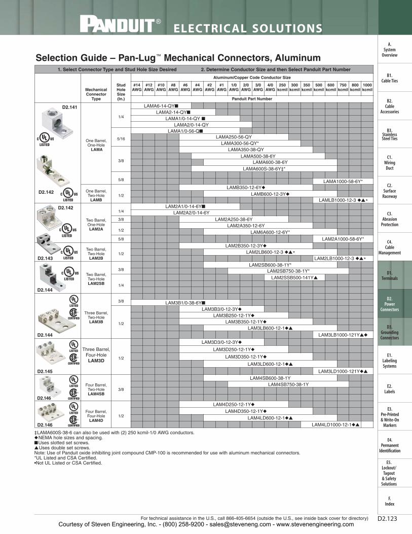
1. Select Connector Type and Stud Hole Size Desired 2. Determine Conductor Size and then Select Panduit Part Number
Mechanical Connector
Type
Stud Hole Size(In.)
Aluminum/Copper Code Conductor Size
#14AWG
#12AWG
#10AWG
#8AWG
#6AWG
#4AWG
#2AWG
#1AWG
1/0AWG
2/0AWG
3/0AWG
4/0AWG
250kcmil
300kcmil
350kcmil
500kcmil
600kcmil
750kcmil
800kcmil
1000kcmil
Panduit Part Number
One Barrel, One-Hole
LAMA
1/4
LAMA6-14-QY■
LAMA2-14-QY■
LAMA1/0-14-QY ■LAMA2/0-14-QY
5/16
LAMA1/0-56-Q■
LAMA250-56-QYLAMA300-56-QY*
3/8
LAMA350-38-QYLAMA500-38-6Y
LAMA600-38-6YLAMA600S-38-6Y‡*
5/8 LAMA1000-58-6Y*
One Barrel,Two-Hole
LAMB1/2
LAMB350-12-6Y◆
LAMB600-12-3Y◆
LAMLB1000-12-3 ◆▲*
Two Barrel,One-HoleLAM2A
1/4LAM2A1/0-14-6Y■
LAM2A2/0-14-6Y 3/8 LAM2A250-38-6Y
1/2LAM2A350-12-6Y
LAM6A600-12-6Y*5/8 LAM2A1000-58-6Y*
Two Barrel, Two-HoleLAM2B
1/2
LAM2B350-12-3Y◆
LAM2LB600-12-3 ◆▲*
LAM2LB1000-12-3 ◆▲*
Two Barrel, Two-HoleLAM2SB
3/8LAM2SB600-38-1Y*
LAM2SB750-38-1Y*
1/4
LAM2SSB500-141Y▲
Three Barrel, Two-HoleLAM3B
3/8 LAM3B1/0-38-6Y■
1/2
LAM3B3/0-12-3Y◆
LAM3B250-12-1Y◆
LAM3B350-12-1Y◆
LAM3LB600-12-1◆▲
LAM3LB1000-121Y▲◆
Three Barrel, Four-HoleLAM3D 1/2
LAM3D3/0-12-3Y◆
LAM3D250-12-1Y◆
LAM3D350-12-1Y◆
LAM3LD600-12-1◆▲
LAM3LD1000-121Y◆▲
Four Barrel, Two-HoleLAM4SB
3/8
LAM4SB600-38-1YLAM4SB750-38-1Y
Four Barrel, Four-HoleLAM4D
1/2
LAM4D250-12-1Y◆
LAM4D350-12-1Y◆
LAM4LD600-12-1◆▲
LAM4LD1000-12-1◆▲
For technical assistance in the U.S., call 866-405-6654 (outside the U.S., see inside back cover for directory)
ELECTRICAL SOLUTIONS
D2.123
‡LAMA600S-38-6 can also be used with (2) 250 kcmil-1/0 AWG conductors.◆NEMA hole sizes and spacing.■Uses slotted set screws.▲Uses double set screws.Note: Use of Panduit oxide inhibiting joint compound CMP-100 is recommended for use with aluminum mechanical connectors.*UL Listed and CSA Certified.•Not UL Listed or CSA Certified.
Selection Guide – Pan-Lug™ Mechanical Connectors, Aluminum
B2.Cable
Accessories
C1.Wiring
Duct
C3.Abrasion
Protection
C4.Cable
Management
D1.Terminals
D2.Power
Connectors
E1.LabelingSystems
E2.Labels
E3.Pre-Printed & Write-On
Markers
F.Index
B3.StainlessSteel Ties
C2.Surface
Raceway
E5.Lockout/Tagout
& SafetySolutions
B1.Cable Ties
A.System
Overview
D3.GroundingConnectors
E4.Permanent
Identification
D2.146
D2.146
D2.145
D2.144
D2.144
D2.143
D2.142
D2.141
D2.142
Courtesy of Steven Engineering, Inc. - (800) 258-9200 - [email protected] - www.stevenengineering.com

ELECTRICAL SOLUTIONS
Prime items appear in BOLD.D2.124
B2.Cable
Accessories
C1.Wiring
Duct
C3.Abrasion
Protection
C4.Cable
Management
D1.Terminals
D2.Power
Connectors
E1.LabelingSystems
E2.Labels
E3.Pre-Printed & Write-On
Markers
F.Index
B3.StainlessSteel Ties
C2.Surface
Raceway
E5.Lockout/Tagout
& SafetySolutions
B1.Cable Ties
A.System
Overview
D3.GroundingConnectors
E4.Permanent
Identification
1. Select Split Bolt Style Desired 2. Determine Conductor Range and then Select Panduit Part Number
Tin Plated CopperSplit Bolt Connectors – SBCT For Use with Combinations of Copper and Aluminum Conductors
Dual Rated AluminumSplit Bolt Connectors – SBAFor Use with Aluminum and Copper Conductor Combinations
Copper Split BoltConnectors – SBCFor Use with Copper Code Conductors
^Long body accommodates two tap conductors with single run; not CSA Certified.**The conductor sizes shown are for equal run and tap combinations
^Not CSA Certified.
Multi-Tap Connectors with Clear InsulationFor Use with Aluminum and Copper Code Conductor Combinations
Selection Guide – Pan-Lug™ Mechanical Connectors, Split Bolts and Multi-Taps
D2.149 – D2.154
PanduitPart Number
Conductor Size Range** PanduitPart Number
Copper Conductor Range**
Min. Max. Min. Max.SBC8-C #10 STR #8 STR SBC1/0-L #4 STR 1/0 STRSBC8L-C^ #16 STR #8 STR SBC2/0-Q #2 STR 2/0 STRSBC6S-C #8 STR #6 STR SBC3/0-Q #1 STR 3/0 STRSBC6SL-C^ #8 STR #6 STR SBC250-Q #1 STR 250 kcmilSBC4S-C #8 STR #6 STR SBC350-1 2/0 STR 350 kcmilSBC4SL-C^ #8 STR #6 STR SBC500-1 300 kcmil 500 kcmilSBC3-C #8 STR #4 STR SBC750-1 #8 SOL 750 kcmilSBC2-C #6 STR #2 STR
SBC1000-1 #8 SOL 1000 kcmilSBC2L-C^ #14 STR #2 STR
Type Description No. of PortsCopper or Aluminum Code
Conductor RangePCSB Double-sided wire entry 2 to 14 14 AWG Solid to 750 kcmil
PCSB-S Single-sided wire entry 2 to 14 14 AWG Solid to 750 kcmil
PISR In-Line Splice/Reducer 2 14 AWG Stranded to 500 kcmil
PCSBMT Double-sided wire entry mountable 4 to 12 14 AWG Solid to 600 kcmil
PSCBMT-S Single-sided wire entry mountable 4 to 12 14 AWG Solid to 600 kcmil
PanduitPart Number
Copper and Aluminum Conductor Range
Range of Equal Run and Tap Min. Tap with One Max. RunMin. Max.
SBCT8-C #8 STR #6 SOL #14 STR
SBCT6-C #6 STR #10 STR #10 STR
SBCT3-C #8 STR #4 STR #10 STR
SBCT2-C #6 STR #2 STR #14 STR
SBCT1/0-L #4 STR 1/0 STR #10 STRSBCT2/0-Q #2 STR 2/0 STR #8 STR
Copper Conductor RangeSBCT10-C #16 STR #10 STR #16 STR
SBCT3/0-Q #1 STR 3/0 STR #8 STRSBCT250-Q #1 STR 250 kcmil #8 STR
SBCT350-1 2/0 STR 350 kcmil 1/0 STR
SBCT500-1 300 kcmil 500 kcmil 2/0 STR
SBCT750-1 2/0 STR 750 kcmil 2/0 STR
SBCT1000-1 4/0 STR 1000 kcmil 4/0 STR
Panduit Part Number
Aluminum to Aluminum, Aluminum to Copper, Copper to Copper Conductors
Max. Run to Max. Tap Min. Run to Min. Tap Max. Run to Min. TapSBA6-C #6 STR – #6 STR #10 SOL – #10 SOL #6 STR – #10 SOL
SBA4-C #4 STR – #4 STR #8 SOL – #10 SOL #4 STR – #10 SOL
SBA2-C #2 STR – #2 STR #6 SOL – #8 STR #2 STR – #8 STR
SBA1/0-Q 1/0 STR – 1/0 STR #2 STR (Compact) – #8 SOL 1/0 STR – #8 SOL
SBA2/0-Q 2/0 STR – 2/0 STR #2 STR (Compact) – #8 STR 2/0 STR – #8 STR
SBA4/0-Q 4/0 STR – 4/0 STR #2 STR (Compact) – #6 STR 4/0 STR – #6 STR
SBA350-1^ 350 kcmil – 350 kcmil 1/0 STR (Compact) – #4 STR 350 kcmil – #4 STR
SBA500-1^ 500 kcmil – 500 kcmil 400 kcmil (Compact) – #2 STR(Compact)
500 kcmil – #2 STR(Compact)
Courtesy of Steven Engineering, Inc. - (800) 258-9200 - [email protected] - www.stevenengineering.com

For technical assistance in the U.S., call 866-405-6654 (outside the U.S., see inside back cover for directory)
ELECTRICAL SOLUTIONS
D2.125
B2.Cable
Accessories
C1.Wiring
Duct
C3.Abrasion
Protection
C4.Cable
Management
D1.Terminals
D2.Power
Connectors
E1.LabelingSystems
E2.Labels
E3.Pre-Printed & Write-On
Markers
F.Index
B3.StainlessSteel Ties
C2.Surface
Raceway
E5.Lockout/Tagout
& SafetySolutions
B1.Cable Ties
A.System
Overview
D3.GroundingConnectors
E4.Permanent
Identification
Split Bolt, Copper
*Long body accommodates two tap conductors with single run; not CSA Certified.
• Made from high strength copper alloy to resist corrosion andprovide premium electrical and mechanical performance
• Offered with extra long body to allow connection of one or two taps to a single run conductor
• Wide wire range-taking capability minimizes inventory requirements
• Nut hex provides correct fit with socket, box, or open endwrenches resulting in proper torquing of electrical connection
• Pressure bar provides secure connection on a full range ofconductor combinations used with each connector assuringpremium wire pull-out strength
• UL Listed and CSA Certified for use up to 600 V and temperaturerated 90°C
L
W
E
For Use with Copper Code Conductors
Type SBC
Part Number
Copper Conductor Max. ConductorFigure Dimensions
(In.)Std.Pkg.Qty.
Range of Equal Run & Tap Min. Tap with OneMax. Run
Copperweld
E W LMin. Max. STR
SBC8-C #10 STR #8 STR #16 STR — 0.39 0.55 0.86 100
SBC8L-C* #16 STR #8 STR #16 STR — 0.38 0.50 0.84 100
SBC6S-C #8 STR #6 STR #16 STR — 0.41 0.62 0.95 100
SBC6SL-C* #8 STR #6 STR #16 STR — 0.41 0.63 1.10 100
SBC4S-C #8 STR #6 STR #14 STR — 0.45 0.69 0.98 100
SBC4SL-C* #8 STR #6 STR #14 STR — 0.45 0.69 1.30 100
SBC3-C #8 STR #4 STR #14 STR — 0.58 0.81 1.16 100
SBC2-C #6 STR #2 STR #14 STR — 0.59 0.86 1.23 100
SBC2L-C* #14 STR #2 STR #14 STR 3 No. 7 0.63 0.81 1.55 100
SBC1/0-L #4 STR 1/0 STR #14 STR — 0.75 0.93 1.55 50
SBC2/0-Q #2 STR 2/0 STR #14 STR — 0.79 1.05 1.72 25
SBC3/0-Q #1 STR 3/0 STR #8 STR — 0.95 1.24 2.07 25
SBC250-Q #1 STR 250 kcmil #8 STR — 1.03 1.36 2.09 25
SBC350-1 2/0 STR 350 kcmil 1/0 STR — 1.16 1.48 2.42 1
SBC500-1 300 kcmil 500 kcmil 2/0 STR — 1.33 1.74 2.83 1
SBC750-1 #8 SOL 750 kcmil #8 SOL 19 No. 5 1.94 2.13 3.75 1
SBC1000-1 #8 SOL 1000 kcmil #8 SOL — 2.25 2.50 4.00 1
Courtesy of Steven Engineering, Inc. - (800) 258-9200 - [email protected] - www.stevenengineering.com
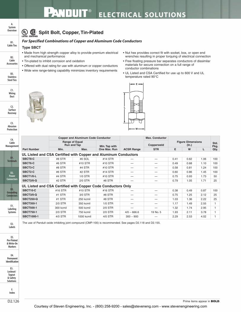
ELECTRICAL SOLUTIONS
Prime items appear in BOLD.D2.126
B2.Cable
Accessories
C1.Wiring
Duct
C3.Abrasion
Protection
C4.Cable
Management
D1.Terminals
D2.Power
Connectors
E1.LabelingSystems
E2.Labels
E3.Pre-Printed & Write-On
Markers
F.Index
B3.StainlessSteel Ties
C2.Surface
Raceway
E5.Lockout/Tagout
& SafetySolutions
B1.Cable Ties
A.System
Overview
D3.GroundingConnectors
E4.Permanent
Identification
Split Bolt, Copper, Tin-Plated
The use of Panduit oxide inhibiting joint compound (CMP-100) is recommended. See pages D2.118 and D2.155.
• Made from high strength copper alloy to provide premium electricaland mechanical performance
• Tin-plated to inhibit corrosion and oxidation
• Offered with dual rating for use with aluminum or copper conductors
• Wide wire range-taking capability minimizes inventory requirements
• Nut hex provides correct fit with socket, box, or open endwrenches resulting in proper torquing of electrical connection
• Free floating pressure bar separates conductors of dissimilarmaterials for secure connection on a full range of conductor combinations
• UL Listed and CSA Certified for use up to 600 V and ULtemperature rated 90°C
For Specified Combinations of Copper and Aluminum Code Conductors
Type SBCT
L
W
E
Part Number
Copper and Aluminum Code Conductor
ACSR Range
Max. ConductorFigure Dimensions
(In.)Std.Pkg.Qty.
Range of Equal Run and Tap Min. Tap with
One Max. Run
Copperweld
Min. Max. STR E W L
UL Listed and CSA Certified with Copper and Aluminum ConductorsSBCT8-C #8 STR #6 SOL #14 STR — — 0.41 0.62 1.06 100
SBCT6-C #6 STR #10 STR #10 STR — — 0.49 0.68 1.10 100
SBCT3-C #8 STR #4 STR #10 STR — — 0.58 0.81 1.24 100
SBCT2-C #6 STR #2 STR #14 STR — — 0.60 0.86 1.45 100
SBCT1/0-L #4 STR 1/0 STR #10 STR — — 0.75 0.93 1.73 50
SBCT2/0-Q #2 STR 2/0 STR #8 STR — — 0.79 1.05 1.71 25
UL Listed and CSA Certified with Copper Code Conductors OnlySBCT10-C #16 STR #10 STR #16 STR — — 0.38 0.49 0.87 100
SBCT3/0-Q #1 STR 3/0 STR #8 STR — — 0.75 1.25 2.12 25
SBCT250-Q #1 STR 250 kcmil #8 STR — — 1.03 1.36 2.22 25
SBCT350-1 2/0 STR 350 kcmil 1/0 STR — — 1.17 1.49 2.55 1
SBCT500-1 300 kcmil 500 kcmil 2/0 STR — — 1.32 1.74 2.95 1
SBCT750-1 2/0 STR 750 kcmil 2/0 STR 4/0 – 666.6 19 No. 5 1.93 2.11 3.78 1
SBCT1000-1 4/0 STR 1000 kcmil 4/0 STR 300 – 900 — 2.29 2.53 4.02 1
Courtesy of Steven Engineering, Inc. - (800) 258-9200 - [email protected] - www.stevenengineering.com

For technical assistance in the U.S., call 866-405-6654 (outside the U.S., see inside back cover for directory)
ELECTRICAL SOLUTIONS
D2.127
B2.Cable
Accessories
C1.Wiring
Duct
C3.Abrasion
Protection
C4.Cable
Management
D1.Terminals
D2.Power
Connectors
E1.LabelingSystems
E2.Labels
E3.Pre-Printed & Write-On
Markers
F.Index
B3.StainlessSteel Ties
C2.Surface
Raceway
E5.Lockout/Tagout
& SafetySolutions
B1.Cable Ties
A.System
Overview
D3.GroundingConnectors
E4.Permanent
Identification
Split Bolt, Aluminum
The use of Panduit oxide inhibiting joint compound (CMP-100) is recommended. See page D2.155.^Not CSA Certified.
Two-Bolt Connector, Bronze
• Made from lightweight, durable aluminum alloy to resist corrosionand provide premium electrical and mechanical performance
• Dual rated for use with aluminum to aluminum, aluminum tocopper, and copper to copper conductor combinations
• Tin-plated to inhibit corrosion and oxidation
• Wide wire range-taking capability minimizes inventory requirements
• True hex design for body and nut hex provides correct fit withsocket, box, or open end wrenches resulting in proper torquing ofelectrical connection
• Free floating pressure bar separates conductors of dissimilarmaterials for secure connection on a full range of conductor combinations
• UL Listed and CSA Certified for use up to 600 V and ULtemperature rated 90°C
For Use with Copper and Aluminum Code ConductorsType SBA
L
W
E
• Made from high strength bronze for heavy duty connections and to inhibit corrosion
• Cap swivels for easy installation of conductors
• Rubber washer retains hardware to connector and eliminates loose parts
• High strength silicon-bronze hardware provides premiummechanical performance when assembled to conductor
• Wide wire range-taking capability minimizes inventory requirements
• UL Listed for use up to 600 V and 90°C temperature rated
For Use with Copper Code Conductors
Type VT
L
W
C
H
^^
Part Number Max. Run to Max. Tap Min. Run to Min. Tap Max. Run to Min. Tap
Figure Dimensions (In.)
Std.Pkg.Qty.E W L
SBA6-C #6 STR – #6 STR #10 SOL – #10 SOL #6 STR – #10 SOL 0.56 0.75 1.58 100
SBA4-C #4 STR – #4 STR #8 SOL – #10 SOL #4 STR – #10 SOL 0.62 0.81 1.38 100
SBA2-C #2 STR – #2 STR #6 SOL – #8 STR #2 STR – #8 STR 0.69 0.94 1.58 100
SBA1/0-Q 1/0 STR – 1/0 STR #2 STR (Compact) – #8 SOL 1/0 STR – #8 SOL 0.75 1.00 1.92 25
SBA2/0-Q 2/0 STR – 2/0 STR #2 STR (Compact) – #8 STR 2/0 STR – #8 STR 0.88 1.12 1.92 25
SBA4/0-Q 4/0 STR – 4/0 STR #2 STR (Compact) – #6 STR 4/0 STR – #6 STR 1.13 1.49 2.54 25
SBA350-1 350 kcmil – 350 kcmil 1/0 STR (Compact) – #4 STR 350 kcmil – #4 STR 1.50 1.69 3.24 1
SBA500-1^ 500 kcmil – 500 kcmil 400 kcmil (Compact) – #2 STR(Compact)
500 kcmil – #2 STR(Compact)
1.73 2.00 3.62 1
Part NumberCopper Conductor Size
Figure Dimensions(In.) Hex Size
(In.)
Std.Pkg.Qty.Run Tap L W H C
VT-0-Q #2 STR – 1/0 STR #10 STR – 1/0 STR 1.50 1.44 0.94 0.31 1/2 25
VT-1-Q #2 STR – 2/0 STR #10 STR – 2/0 STR 1.50 1.56 1.13 0.31 1/2 25
VT-2-Q 1/0 STR – 4/0 STR #10 STR – 4/0 STR 1.75 1.84 1.34 0.38 9/16 25
VT-3-12 250 kcmil – 350 kcmil #10 STR – 350 kcmil 2.00 2.31 1.63 0.50 3/4 12
VT-4-12 250 kcmil – 500 kcmil #10 STR – 500 kcmil 2.25 2.44 1.69 0.50 3/4 12
VT-5-6 400 kcmil – 800 kcmil 3/0 STR – 800 kcmil 2.50 2.69 1.88 0.50 9/16 6
VT-6-6 500 kcmil – 1000 kcmil 3/0 STR – 1000 kcmil 2.75 3.06 2.25 0.63 15/16 6
Courtesy of Steven Engineering, Inc. - (800) 258-9200 - [email protected] - www.stevenengineering.com
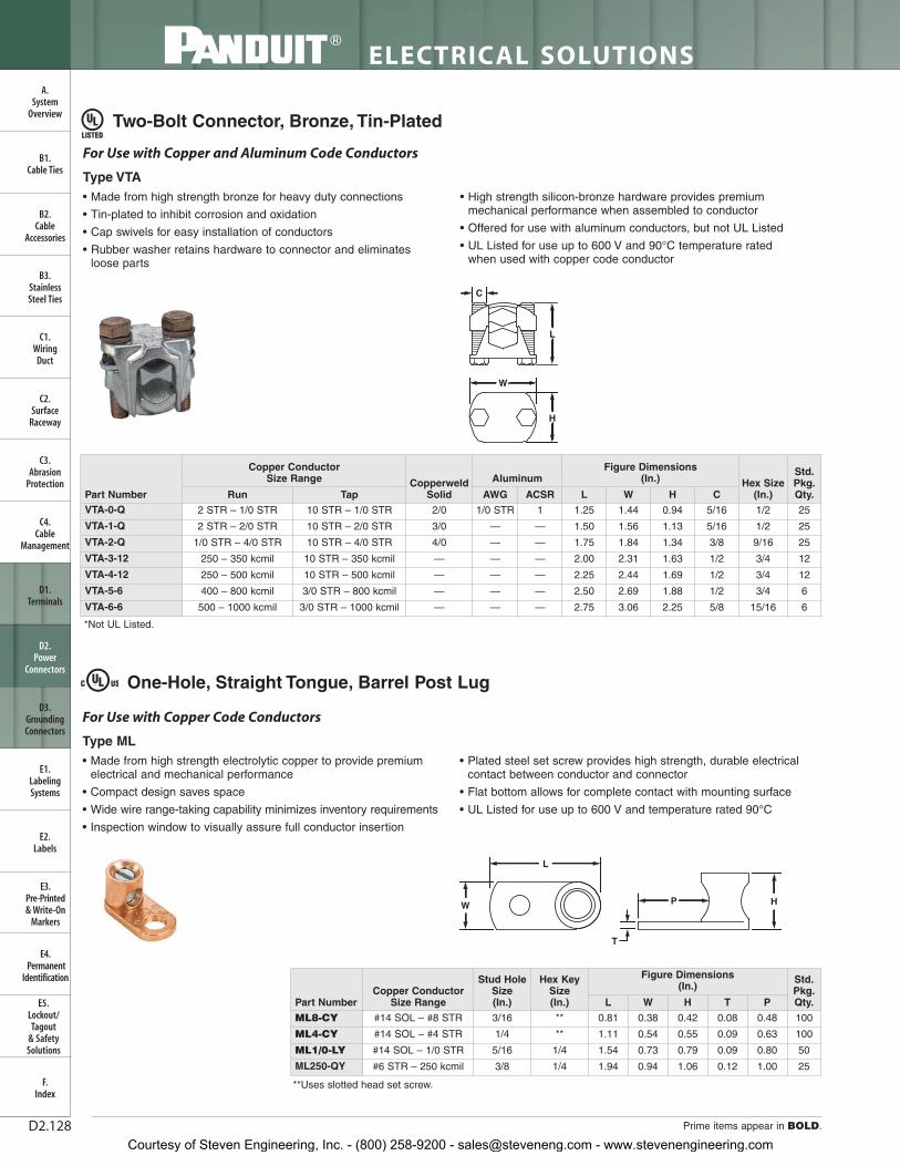
ELECTRICAL SOLUTIONS
Prime items appear in BOLD.D2.128
B2.Cable
Accessories
C1.Wiring
Duct
C3.Abrasion
Protection
C4.Cable
Management
D1.Terminals
D2.Power
Connectors
E1.LabelingSystems
E2.Labels
E3.Pre-Printed & Write-On
Markers
F.Index
B3.StainlessSteel Ties
C2.Surface
Raceway
E5.Lockout/Tagout
& SafetySolutions
B1.Cable Ties
A.System
Overview
D3.GroundingConnectors
E4.Permanent
Identification
Two-Bolt Connector, Bronze, Tin-Plated
*Not UL Listed.
One-Hole, Straight Tongue, Barrel Post Lug
**Uses slotted head set screw.
• Made from high strength bronze for heavy duty connections
• Tin-plated to inhibit corrosion and oxidation
• Cap swivels for easy installation of conductors
• Rubber washer retains hardware to connector and eliminates loose parts
• High strength silicon-bronze hardware provides premiummechanical performance when assembled to conductor
• Offered for use with aluminum conductors, but not UL Listed
• UL Listed for use up to 600 V and 90°C temperature rated when used with copper code conductor
For Use with Copper and Aluminum Code Conductors
Type VTA
W
L
H
C
• Made from high strength electrolytic copper to provide premiumelectrical and mechanical performance
• Compact design saves space
• Wide wire range-taking capability minimizes inventory requirements
• Inspection window to visually assure full conductor insertion
• Plated steel set screw provides high strength, durable electricalcontact between conductor and connector
• Flat bottom allows for complete contact with mounting surface
• UL Listed for use up to 600 V and temperature rated 90°C
For Use with Copper Code Conductors
Type ML
T
L
W HP
Part NumberCopper Conductor
Size Range
Stud HoleSize(In.)
Hex KeySize(In.)
Figure Dimensions (In.)
Std.Pkg.Qty.L W H T P
ML8-CY #14 SOL – #8 STR 3/16 ** 0.81 0.38 0.42 0.08 0.48 100
ML4-CY #14 SOL – #4 STR 1/4 ** 1.11 0.54 0.55 0.09 0.63 100
ML1/0-LY #14 SOL – 1/0 STR 5/16 1/4 1.54 0.73 0.79 0.09 0.80 50
ML250-QY #6 STR – 250 kcmil 3/8 1/4 1.94 0.94 1.06 0.12 1.00 25
Part Number
Copper Conductor Size Range Copperweld
Solid
AluminumFigure Dimensions
(In.) Hex Size(In.)
Std.Pkg.Qty.Run Tap AWG ACSR L W H C
VTA-0-Q 2 STR – 1/0 STR 10 STR – 1/0 STR 2/0 1/0 STR 1 1.25 1.44 0.94 5/16 1/2 25
VTA-1-Q 2 STR – 2/0 STR 10 STR – 2/0 STR 3/0 — — 1.50 1.56 1.13 5/16 1/2 25
VTA-2-Q 1/0 STR – 4/0 STR 10 STR – 4/0 STR 4/0 — — 1.75 1.84 1.34 3/8 9/16 25
VTA-3-12 250 – 350 kcmil 10 STR – 350 kcmil — — — 2.00 2.31 1.63 1/2 3/4 12
VTA-4-12 250 – 500 kcmil 10 STR – 500 kcmil — — — 2.25 2.44 1.69 1/2 3/4 12
VTA-5-6 400 – 800 kcmil 3/0 STR – 800 kcmil — — — 2.50 2.69 1.88 1/2 3/4 6
VTA-6-6 500 – 1000 kcmil 3/0 STR – 1000 kcmil — — — 2.75 3.06 2.25 5/8 15/16 6
Courtesy of Steven Engineering, Inc. - (800) 258-9200 - [email protected] - www.stevenengineering.com

For technical assistance in the U.S., call 866-405-6654 (outside the U.S., see inside back cover for directory)
ELECTRICAL SOLUTIONS
D2.129
B2.Cable
Accessories
C1.Wiring
Duct
C3.Abrasion
Protection
C4.Cable
Management
D1.Terminals
D2.Power
Connectors
E1.LabelingSystems
E2.Labels
E3.Pre-Printed & Write-On
Markers
F.Index
B3.StainlessSteel Ties
C2.Surface
Raceway
E5.Lockout/Tagout
& SafetySolutions
B1.Cable Ties
A.System
Overview
D3.GroundingConnectors
E4.Permanent
Identification
One-Hole, Straight Tongue, Tin-Plated, Barrel Post Lug
**Uses slotted head set screw.
One-Hole, Straight Tongue Lug
**Uses slotted head set screw.
• Made from high strength, electrolytic copper to provide premiumelectrical and mechanical performance
• Tin-plated to inhibit corrosion
• Compact design saves space
• Wide wire range-taking capability minimizes inventory requirements
• Inspection window to visually assure full conductor insertion
• Plated steel set screw provides high strength, durable electricalcontact between conductor and connector
• Flat bottom allows for complete contact with mounting surface
• UL Listed for use up to 600 V and temperature rated 90°C
For Use with Copper Code Conductors
Type ML-T
T
L
W HP
• Cast from high strength corrosion resistant copper alloy to providepremium electrical and mechanical performance
• Compact design saves space
• Wide wire range-taking capability minimizes inventory requirements
• Inspection window to visually assure full conductor insertion
• Plated steel set screw provides high strength, durable electricalcontact between conductor and connector
• Flat bottom allows for complete contact with mounting surface
• UL Listed and CSA Certified for use up to 600 V and ULtemperature rated 90°C
For Use with Copper Code Conductors
Type PNL
L
W H
T
P
Part NumberCopper Conductor
Size Range
Stud HoleSize(In.)
Hex KeySize(In.)
Figure Dimensions (In.)
Std.Pkg.Qty.L W H T P
ML8T-CY #14 SOL – #8 STR 3/16 ** 0.81 0.38 0.42 0.08 0.48 100
ML4T-CY #14 SOL – #4 STR 1/4 ** 1.11 0.54 0.55 0.09 0.63 100
ML1/0T-LY #14 SOL – 1/0 STR 5/16 1/4 1.58 0.73 0.79 0.09 0.80 50
ML250T-QY #6 STR – 250 kcmil 3/8 1/4 1.94 0.94 1.06 0.12 1.00 25
Part NumberCopper Conductor
Size Range
Stud HoleSize(In.)
Hex KeySize(In.)
Figure Dimensions (In.)
Std.Pkg.Qty.L W H T P
PNL-4-C #14 SOL – #4 STR 1/4 ** 1.25 0.53 0.56 0.14 0.66 100
PNL-1/0-L #8 SOL – 1/0 STR 5/16 1/4 1.59 0.73 0.78 0.14 0.85 50
PNL-250-Q #6 SOL – 250 kcmil 3/8 5/16 1.97 0.94 1.05 0.13 1.00 25
PNL-500-3 #4 SOL – 500 kcmil 1/2 3/8 3.00 1.38 1.47 0.25 1.63 3
PNL-1000-3 500 kcmil – 1000kcmil
1/2 1/2 3.88 1.75 2.00 0.38 2.13 3
Courtesy of Steven Engineering, Inc. - (800) 258-9200 - [email protected] - www.stevenengineering.com

ELECTRICAL SOLUTIONS
Prime items appear in BOLD.D2.130
B2.Cable
Accessories
C1.Wiring
Duct
C3.Abrasion
Protection
C4.Cable
Management
D1.Terminals
D2.Power
Connectors
E1.LabelingSystems
E2.Labels
E3.Pre-Printed & Write-On
Markers
F.Index
B3.StainlessSteel Ties
C2.Surface
Raceway
E5.Lockout/Tagout
& SafetySolutions
B1.Cable Ties
A.System
Overview
D3.GroundingConnectors
E4.Permanent
Identification
One-Hole, Straight Tongue Lug with Internal Pressure Plate
*HL1-25-X and HL4-1-X do not include pressure plates.**Uses slotted head set screw.
One-Hole, Straight Tongue, Flag Lug
**Uses slotted head set screw.
• Cast from high strength corrosion resistant copper alloy to providepremium electrical and mechanical performance
• Compact design saves space
• Wide wire range-taking capability minimizes inventory requirements
• Pressure plate* provides uniform clamping force on conductor for premium electrical performance
• Plated steel set screw provides high strength, durable electricalcontact between conductor and connector
• Flat bottom allows for complete contact with mounting surface
• Inspection window to visually assure full conductor insertion
• UL Listed for use up to 600 V and temperature rated 90°C
For Use with Copper Code Conductors
Type HL
W
L
PT H
• Provides connection of conductor at right angles to terminal bar
• Cast from high strength corrosion resistant copper alloy to providepremium electrical and mechanical performance
• Compact design saves space
• Wire range-taking capability minimizes inventory requirements
• Internal pressure plate provides uniform clamping force onconductor for premium electrical performance
• Flush bottom allows for complete contact with mounting surface
• Inspection window to visually assure full conductor insertion
• UL Listed for use up to 600 V and temperature rated 90°C
For Use with Copper Code Conductors
Type HLB
L
P H
W
T
Part NumberCopper Conductor
Size Range
Stud HoleSize(In.)
Hex KeySize(In.)
Figure Dimensions (In.)
Std.Pkg.Qty.L W H T P
HL1-25-X #14 SOL – #8 STR 1/4 ** 1.38 0.56 0.79 0.19 0.81 10
HL4-1-X #8 SOL – #4 STR 1/4 ** 1.38 0.56 0.79 0.19 0.81 10
HL8-1-X #4 SOL – #1 STR 1/4 7/16 1.56 0.75 0.90 0.22 0.69 10
HL13-1-5 #1 STR – 2/0 STR 3/8 9/16 1.88 0.81 1.14 0.22 0.88 5
HL21-1-5 2/0 STR – 4/0 STR 3/8 9/16 2.19 1.00 1.31 0.25 1.00 5
HL30-1-2 4/0 STR – 300 kcmil 1/2 5/8 2.50 1.06 1.47 0.31 1.25 2
HL50-1-2 300 kcmil – 500 kcmil 1/2 3/4 3.00 1.38 1.65 0.34 1.50 2
Part NumberCopper Conductor
Size Range
Stud HoleSize(In.)
Hex KeySize(In.)
Figure Dimensions (In.)
Std.Pkg.Qty.L W H T P
HLB4-1-X #8 SOL – #4 STR 1/4 ** 1.25 0.50 0.79 0.19 0.63 10
Courtesy of Steven Engineering, Inc. - (800) 258-9200 - [email protected] - www.stevenengineering.com

For technical assistance in the U.S., call 866-405-6654 (outside the U.S., see inside back cover for directory)
ELECTRICAL SOLUTIONS
D2.131
B2.Cable
Accessories
C1.Wiring
Duct
C3.Abrasion
Protection
C4.Cable
Management
D1.Terminals
D2.Power
Connectors
E1.LabelingSystems
E2.Labels
E3.Pre-Printed & Write-On
Markers
F.Index
B3.StainlessSteel Ties
C2.Surface
Raceway
E5.Lockout/Tagout
& SafetySolutions
B1.Cable Ties
A.System
Overview
D3.GroundingConnectors
E4.Permanent
Identification
One-Hole, Straight Tongue, 90° Lug
**Uses slotted head set screw.
Two-Hole, Straight Tongue Lug
• Provides connection of conductor at right angles to terminal bar
• Cast from high strength corrosion resistant copper alloy to providepremium electrical and mechanical performance
• Compact design saves space
• Wide wire range-taking capability minimizes inventory requirements
• Internal pressure plate provides uniform clamping force onconductor for premium electrical performance
• Flush bottom allows for complete contact with mounting surface
• UL Listed for use up to 600 V and temperature rated 90°C
For Use with Copper Code Conductors
Type HLA-90
P T
L
W
H
• Cast from high strength corrosion resistant copper alloy to providepremium electrical and mechanical performance
• Wide wire range-taking capability minimizes inventoryrequirements
• Inspection window to visually assure full conductor insertion
• Plated steel set screw provides high strength, durable electricalcontact between conductor and connector
• Flat bottom allows for complete contact with mounting surface
• UL Listed for use up to 600 V and temperature rated 90°C
For Use with Copper Code Conductors
Type PNL-2
L
W H
HOLESPACING T
P
Part NumberCopper Conductor
Size Range
Stud HoleSize(In.)
Hex KeySize(In.)
Figure Dimensions (In.)
Std.Pkg.Qty.L W H T P
HLA4-1-90-X #8 SOL – #4 STR 1/4 ** 1.81 0.56 0.73 0.19 0.63 10
HLA8-1-90-X #4 SOL – #1 STR 1/4 7/16 1.50 0.75 0.75 0.22 0.69 10
HLA13-1-90-5 #1 STR – 2/0 STR 3/8 9/16 2.38 0.81 1.00 0.22 0.88 5
HLA21-1-90-5 2/0 STR – 4/0 STR 3/8 9/16 2.69 1.00 1.14 0.25 1.00 5
Part NumberCopper Conductor
Size Range
Stud HoleSize(In.)
Stud HoleSpacing
(In.)
Hex KeySize (In.)
Figure Dimensions (In.)
Std.Pkg.Qty.L W H T P
PNL-1/0-2-L #8 SOL – 1/0 STR 5/16 1.00 1/4 2.75 0.75 0.84 0.19 2.00 50
PNL-250-2-Q #6 SOL – 250 kcmil 3/8 1.00 1/4 2.88 0.94 1.03 0.22 2.02 25
PNL-500-2-3 #4 SOL – 500 kcmil 3/8 1.00 3/8 3.38 1.38 1.47 0.31 2.00 3
PNL-1000-2-3 500 kcmil – 1000 kcmil 1/2 1.50 3/8 4.88 1.75 2.00 0.38 3.13 3
Courtesy of Steven Engineering, Inc. - (800) 258-9200 - [email protected] - www.stevenengineering.com

ELECTRICAL SOLUTIONS
Prime items appear in BOLD.D2.132
B2.Cable
Accessories
C1.Wiring
Duct
C3.Abrasion
Protection
C4.Cable
Management
D1.Terminals
D2.Power
Connectors
E1.LabelingSystems
E2.Labels
E3.Pre-Printed & Write-On
Markers
F.Index
B3.StainlessSteel Ties
C2.Surface
Raceway
E5.Lockout/Tagout
& SafetySolutions
B1.Cable Ties
A.System
Overview
D3.GroundingConnectors
E4.Permanent
Identification
Two-Hole, Straight Tongue Lug with Internal Pressure Plate
**Uses slotted head set screw.
• Cast from high strength corrosion resistant copper alloy to providepremium electrical and mechanical performance
• Wide wire range-taking capability minimizes inventory requirements
• Internal pressure plate provides uniform clamping force onconductor for premium electrical performance
• Plated steel set screw provides high strength, durable electricalcontact between conductor and connector
• Inspection window to visually assure full conductor insertion
• Flat bottom allows for complete contact with mounting surface
• UL Listed for use up to 600 V and temperature rated 90°C
For Use with Copper Code Conductors
Type HL-2
P
HOLESPACING
L
W
T H
Part NumberCopper Conductor
Size Range
Stud HoleSize(In.)
Stud HoleSpacing
(In.)Hex KeySize (In.)
Figure Dimensions (In.)
Std.Pkg.Qty.L W H T P
HL1-2-25-X #14 SOL – #8 STR 1/4 0.63 ** 2.00 0.56 0.70 0.19 1.25 10
HL4-2-X #8 SOL – #4 STR 1/4 0.63 ** 2.00 0.56 0.69 0.18 1.25 10
HL8-2-X #4 SOL – #1 STR 1/4 0.75 7/16 2.44 0.75 0.92 0.22 1.50 10
HL13-2-5 #1 STR – 2/0 STR 3/8 1.00 9/16 2.88 0.81 1.07 0.22 1.88 5
HL21-2-5 2/0 STR – 4/0 STR 3/8 1.00 9/16 3.00 1.00 1.33 0.25 1.75 5
HL30-2-2 4/0 STR – 300 kcmil 3/8 1.00 5/8 3.13 1.06 1.45 0.31 2.00 2
HL50-2-2 300 kcmil – 500 kcmil 3/8 1.00 3/4 3.44 1.38 1.66 0.34 2.00 2
Courtesy of Steven Engineering, Inc. - (800) 258-9200 - [email protected] - www.stevenengineering.com
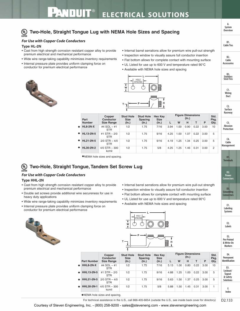
For technical assistance in the U.S., call 866-405-6654 (outside the U.S., see inside back cover for directory)
ELECTRICAL SOLUTIONS
D2.133
B2.Cable
Accessories
C1.Wiring
Duct
C3.Abrasion
Protection
C4.Cable
Management
D1.Terminals
D2.Power
Connectors
E1.LabelingSystems
E2.Labels
E3.Pre-Printed & Write-On
Markers
F.Index
B3.StainlessSteel Ties
C2.Surface
Raceway
E5.Lockout/Tagout
& SafetySolutions
B1.Cable Ties
A.System
Overview
D3.GroundingConnectors
E4.Permanent
Identification
Two-Hole, Straight Tongue Lug with NEMA Hole Sizes and Spacing
◆NEMA hole sizes and spacing.
• Cast from high strength corrosion resistant copper alloy to providepremium electrical and mechanical performance
• Wide wire range-taking capability minimizes inventory requirements
• Internal pressure plate provides uniform clamping force onconductor for premium electrical performance
• Internal barrel serrations allow for premium wire pull-out strength
• Inspection window to visually assure full conductor insertion
• Flat bottom allows for complete contact with mounting surface
• UL Listed for use up to 600 V and temperature rated 90°C
• Available with NEMA hole sizes and spacing
For Use with Copper Code ConductorsType HL-2N
W
L
PT
HOLESPACING
H
• Cast from high strength corrosion resistant copper alloy to providepremium electrical and mechanical performance
• Double set screws provide additional wire secureness for use inheavy duty applications
• Wide wire range-taking capability minimizes inventory requirements
• Internal pressure plate provides uniform clamping force onconductor for premium electrical performance
• Internal barrel serrations allow for premium wire pull-out strength
• Inspection window to visually assure full conductor insertion
• Flat bottom allows for complete contact with mounting surface
• UL Listed for use up to 600 V and temperature rated 90°C
• Available with NEMA hole sizes and spacing
For Use with Copper Code ConductorsType HHL-2N
W
L
P
T
HOLESPACING
H
Two-Hole, Straight Tongue, Tandem Set Screw Lug
◆NEMA hole sizes and spacing.
PartNumber
CopperConductorSize Range
Stud HoleSize(In.)
Stud HoleSpacing
(In.)
Hex Key Size (In.)
Figure Dimensions (In.)
Std.Pkg.Qty.L W H T P
◆ HL8-2N-X #4 SOL – #1STR
1/2 1.75 7/16 3.94 1.00 0.90 0.22 3.00 10
◆ HL13-2N-5 #1 STR – 2/0STR
1/2 1.75 9/16 4.25 1.00 1.07 0.22 3.00 5
◆ HL21-2N-5 2/0 STR – 4/0STR
1/2 1.75 9/16 4.19 1.25 1.34 0.25 3.00 5
◆ HL30-2N-2 4/0 STR – 300kcmil
1/2 1.75 5/8 4.25 1.25 1.46 0.31 3.00 2
Part Number
CopperConductorSize Range
Stud HoleSize(In.)
Stud HoleSpacing
(In.)
Hex KeySize(In.)
Figure Dimensions (In.)
Std.Pkg.Qty.L W H T P
◆ HHL8-2N-X #4 SOL – #1STR
1/2 1.75 7/16 5.13 1.00 0.80 0.22 3.00 10
◆ HHL13-2N-5 #1 STR – 2/0STR
1/2 1.75 9/16 4.88 1.25 1.00 0.22 3.00 5
◆ HHL21-2N-5 2/0 STR – 4/0STR
1/2 1.75 9/16 5.63 1.50 1.37 0.25 3.00 5
◆ HHL30-2N-1 4/0 STR – 300kcmil
1/2 1.75 5/8 5.88 1.50 1.45 0.31 3.00 1
Courtesy of Steven Engineering, Inc. - (800) 258-9200 - [email protected] - www.stevenengineering.com

ELECTRICAL SOLUTIONS
Prime items appear in BOLD.D2.134
B2.Cable
Accessories
C1.Wiring
Duct
C3.Abrasion
Protection
C4.Cable
Management
D1.Terminals
D2.Power
Connectors
E1.LabelingSystems
E2.Labels
E3.Pre-Printed & Write-On
Markers
F.Index
B3.StainlessSteel Ties
C2.Surface
Raceway
E5.Lockout/Tagout
& SafetySolutions
B1.Cable Ties
A.System
Overview
D3.GroundingConnectors
E4.Permanent
Identification
**Uses slotted head set screw.◆NEMA hole sizes and spacing.
Two-Hole, Straight Tongue, Two-Barrel, Tin-Plated Lug
◆NEMA hole sizes and spacing.
• Allows for termination of two copper conductors
• Cast from high strength corrosion resistant copper alloy to providepremium electrical and mechanical performance
• Wide wire range-taking capability minimizes inventory requirements
• Internal pressure plate provides uniform clamping force onconductor for premium electrical performance
• Internal barrel serrations provide premium wire pull-out strength
• Inspection window to visually assure full conductor insertion
• Flat bottom allows for complete contact with mounting surface
• UL Listed for use up to 600 V and temperature rated 90°C
• Available with NEMA hole sizes and spacing
For Use with Copper Code ConductorsType H2L-2N
H
HOLESPACING
PT
W
L
• Allows for termination of two copper conductors
• Cast from high strength corrosion resistant copper alloy to provide premium electrical and mechanical performance
• Tin-plated to inhibit corrosion
• Wide wire range-taking capability minimizes inventory requirements
• Internal barrel serrations provide premium wire pull-out strength
• Inspection window to visually assure full conductor insertion
• Plated steel set screw provides high strength, durable electrical contact
• Flat bottom allows for complete contact with mounting surface
• UL Listed for use up to 600 V and temperature rated 90°C
• Available with NEMA hole sizes and spacing
For Use with Copper Code ConductorsType P2NLT
HT
P
L
HOLESPACING
W
Two-Hole, Straight Tongue, Two-Barrel Lug
Part Number
CopperConductorSize Range
Stud HoleSize(In.)
Stud HoleSpacing
(In.)
Hex KeySize(In.)
Figure Dimensions (In.)
Std.Pkg.Qty.L W H T P
◆ H2L4-2N-X #8 SOL – #4STR
1/2 1.75 ** 3.75 1.25 0.76 0.19 3.00 10
◆ H2L8-2N-2 #4 SOL – #1STR
1/2 1.75 7/16 3.94 1.38 0.92 0.22 3.00 2
◆ H2L13-2N-2 #1 STR – 2/0STR
1/2 1.75 9/16 4.00 1.63 1.06 0.22 3.00 2
◆ H2L21-2N-2 2/0 STR – 4/0STR
1/2 1.75 9/16 4.19 1.88 1.34 0.31 3.00 2
◆ H2L30-2N-1 4/0 STR – 300kcmil
1/2 1.75 5/8 4.38 2.00 1.45 0.31 3.00 1
Part Number
CopperConductorSize Range
Stud HoleSize(In.)
Stud HoleSpacing
(In.)
Hex KeySize(In.)
Figure Dimensions (In.)
Std.Pkg.Qty.L W H T P
◆ P2NLT-500-3 #4 SOL – 500kcmil
1/2 1.75 3/8 4.50 2.50 1.47 0.38 3.00 3
Courtesy of Steven Engineering, Inc. - (800) 258-9200 - [email protected] - www.stevenengineering.com

For technical assistance in the U.S., call 866-405-6654 (outside the U.S., see inside back cover for directory)
ELECTRICAL SOLUTIONS
D2.135
B2.Cable
Accessories
C1.Wiring
Duct
C3.Abrasion
Protection
C4.Cable
Management
D1.Terminals
D2.Power
Connectors
E1.LabelingSystems
E2.Labels
E3.Pre-Printed & Write-On
Markers
F.Index
B3.StainlessSteel Ties
C2.Surface
Raceway
E5.Lockout/Tagout
& SafetySolutions
B1.Cable Ties
A.System
Overview
D3.GroundingConnectors
E4.Permanent
Identification
Two-Set Screw Splice
Two-Set Screw Splice with Internal Pressure Plate
*Includes swivel screws, not internal pressure plate.**Uses slotted head set screw.
• Cast from high strength corrosion resistant copper alloy to providepremium electrical and mechanical performance
• Wide wire range-taking capability minimizes inventory requirements
• Plated steel set screw provides high strength, durable electricalcontact between conductor and connector
• Internal wire stops to prevent over-insertion of conductor
• For use up to 600 V and temperature rated 90°C
For Use with Copper Code Conductors
Type PNLC
W
L
H
• Cast from high strength corrosion resistant copper alloy to providepremium electrical and mechanical performance
• Wide wire range-taking capability minimizes inventory requirements
• Internal pressure plate provides uniform clamping force onconductor for premium electrical performance
• Internal barrel serrations provide premium wire pull-out strength
• Internal wire stops to prevent over-insertion of conductor
• UL Listed for use up to 600 V and temperature rated 90°C
For Use with Copper Code Conductors
Type HC
W
L
H
Part NumberCopper Conductor
Size RangeHex Key Size
(In.)
Figure Dimensions (In.)
Std.Pkg.Qty.L W H
PNLC-1/0-3 #8 SOL – 1/0 STR 1/4 1.63 0.72 0.84 3
PNLC-250-1 #6 SOL – 250 kcmil 3/8 2.13 0.97 1.06 1
PNLC-500-1 #4 SOL – 500 kcmil 3/8 3.00 1.38 1.47 1
Part NumberCopper Conductor
Size RangeHex Key Size
(In.)
Figure Dimensions (In.)
Std.Pkg.Qty.L W H
HC4-3* #8 SOL – #4 STR ** 1.25 0.50 0.56 3
HC8-3* #4 SOL – #1 STR 7/16 1.75 0.69 0.81 3
HC13-3 #1 STR – 2/0 STR 1/4 2.00 0.81 0.94 3
HC21-1 2/0 STR – 4/0 STR 9/16 2.25 1.00 1.19 1
HC30-1 4/0 STR – 300 kcmil 5/16 2.56 1.19 1.44 1
HC50-1 300 kcmil – 500 kcmil 3/4 3.00 1.38 1.63 1
Courtesy of Steven Engineering, Inc. - (800) 258-9200 - [email protected] - www.stevenengineering.com

ELECTRICAL SOLUTIONS
Prime items appear in BOLD.D2.136
B2.Cable
Accessories
C1.Wiring
Duct
C3.Abrasion
Protection
C4.Cable
Management
D1.Terminals
D2.Power
Connectors
E1.LabelingSystems
E2.Labels
E3.Pre-Printed & Write-On
Markers
F.Index
B3.StainlessSteel Ties
C2.Surface
Raceway
E5.Lockout/Tagout
& SafetySolutions
B1.Cable Ties
A.System
Overview
D3.GroundingConnectors
E4.Permanent
Identification
One-Hole, Straight Fixed Tongue Lug
*cULus Listed for use up to 600V.**Uses slotted head set screw.
One-Hole, Straight Fixed Tongue, Tin-Plated Lug
*cULus Listed for use up to 600V.**Uses slotted head set screw.
• Made from high strength electrolytic copper to provide premiumelectrical and mechanical performance
• Compact design saves space
• Wide wire range-taking capability minimizes inventory requirements
• Inspection window to visually assure full conductor insertion
• Plated steel set screw provides high strength, durable electricalcontact between conductor and connector
• UL Listed and CSA Certified for use up to 600 V
For Use with Stranded Copper Code Conductors
Type CX
W
L
H
M
T
P
• Made from high strength electrolytic copper to provide premiumelectrical and mechanical performance
• Tin-plated to inhibit corrosion
• Compact design saves space
• Wide wire range-taking capability minimizes inventory requirements
• Inspection window to visually assure full conductor insertion
• Plated steel set screw provides high strength, durable electricalcontact between conductor and connector
• UL Listed and CSA Certified for use up to 600 V
For Use with Stranded Copper Code Conductors
Type CX-T
W
L
H
M
T
P
Part NumberCopper Conductor
Size RangeCurrent
Rating (Amps)
Stud HoleSize(In.)
Hex Size(In.)
Figure Dimensions (In.)
Std.Pkg.Qty.L W H T P M
CX35-36-CY #14 AWG – #6 AWG 35 3/16 ** 1.02 0.38 0.48 0.07 0.44 0.38 100
CX70-14-CY #14 AWG – #4 AWG, (2) #14 AWG, (2) #12 AWG
70 1/4 ** 1.27 0.50 0.57 0.08 0.59 0.50 100
CX125-14-QY* #4 AWG – 1/0 AWG 125 1/4 ** 1.53 0.62 0.77 0.13 0.84 0.62 25
CX225-56-QY* #2 AWG – 4/0 AWG 225 5/16 3/16 2.19 1.00 1.13 0.13 1.06 1.00 25
Part NumberCopper Conductor
Size RangeCurrent
Rating (Amps)
Stud HoleSize(In.)
Hex Size(In.)
Figure Dimensions (In.)
Std.Pkg.Qty.L W H T P M
CX35-36T-CY #14 AWG – #6 AWG 35 3/16 ** 1.02 0.38 0.48 0.07 0.44 0.38 100
CX70-14T-CY #14 AWG – #4 AWG, (2) #14 AWG, (2) #12 AWG
70 1/4 ** 1.27 0.50 0.57 0.08 0.59 0.50 100
CX125-56T-QY* #4 AWG – 1/0 AWG 125 5/16 ** 1.53 0.62 0.77 0.13 0.84 0.62 25
CX225-38T-QY* #2 AWG – 4/0 AWG 225 3/8 3/16 2.19 1.00 1.13 0.13 1.06 1.00 25
CX225-56T-QY* #2 AWG – 4/0 AWG 225 5/16 3/16 2.19 1.00 1.13 0.13 1.06 1.00 25
Courtesy of Steven Engineering, Inc. - (800) 258-9200 - [email protected] - www.stevenengineering.com

For technical assistance in the U.S., call 866-405-6654 (outside the U.S., see inside back cover for directory)
ELECTRICAL SOLUTIONS
D2.137
B2.Cable
Accessories
C1.Wiring
Duct
C3.Abrasion
Protection
C4.Cable
Management
D1.Terminals
D2.Power
Connectors
E1.LabelingSystems
E2.Labels
E3.Pre-Printed & Write-On
Markers
F.Index
B3.StainlessSteel Ties
C2.Surface
Raceway
E5.Lockout/Tagout
& SafetySolutions
B1.Cable Ties
A.System
Overview
D3.GroundingConnectors
E4.Permanent
Identification
One-Hole, Straight Floating Tongue Lug
**Uses slotted head set screw.
• Made from high strength electrolytic copper to provide premiumelectrical and mechanical performance
• Wide wire range-taking capability minimizes inventoryrequirements
• Internal pressure bar and V-bottom collar provide uniform clampingforce on conductor to assure positive contact between conductorand connector
• Inspection window to visually assure full conductor insertion
• Plated steel set screw provides high strength, durable electricalcontact between conductor and connector
• cULus Listed and CSA Certified for use up to 600 V
For Use with Stranded Copper Code Conductors
Type CS
W
L
H
M
T
P
Part NumberCopper Conductor
Size Range
CurrentRating(Amps)
Stud HoleSize(In.)
Hex Size(In.)
Figure Dimensions (In.)
Std.Pkg.Qty.L W H T P M
CS25-18-CY #14 AWG – #10 AWG 25 1/8 ** 1.16 0.32 0.36 0.07 0.75 0.28 100
CS35-36-CY #14 AWG – #6 AWG, (2) #10 AWG, (2) #12 AWG,
(2) #14 AWG, (1) #10 AWG with (1) #12 AWG, (1) #12 AWG with (1) #14 AWG
50 3/16 ** 1.14 0.38 0.49 0.07 0.60 0.43 100
CSA70-14-CY #14 AWG – #4 AWG 70 1/4 ** 1.30 0.50 0.64 0.08 0.71 0.50 100
CS70-14-CY #12 AWG – #2 AWG, (1) #8 AWG with (1) #4 AWG, (1) #8 AWG with (1) #6 AWG
90 1/4 ** 1.50 0.50 0.64 0.08 0.81 0.50 100
CS125-14-QY #2 AWG – 1/0 AWG 125 1/4 ** 1.94 0.62 0.88 0.13 1.00 0.60 25
CS175-38-QY #4 AWG – 3/0 AWG 175 3/8 3/16 2.19 0.75 1.01 0.16 1.25 0.72 25
CS225-56-QY #6 AWG – 4/0 AWG 225 5/16 3/16 2.38 1.00 1.13 0.13 1.19 0.94 25
CS300-38-QY #1 AWG – 350 kcmil 300 3/8 5/16 3.19 1.00 1.39 0.19 1.63 1.23 25
CS400-38-3Y 1/0 AWG – 500 kcmil 400 3/8 5/16 3.88 1.50 1.61 0.19 2.19 1.41 3
CS650-12-3Y 600 kcmil – 1000 kcmil 650 1/2 3/8 5.13 2.00 2.32 0.25 2.82 1.85 3
Courtesy of Steven Engineering, Inc. - (800) 258-9200 - [email protected] - www.stevenengineering.com

ELECTRICAL SOLUTIONS
Prime items appear in BOLD.D2.138
B2.Cable
Accessories
C1.Wiring
Duct
C3.Abrasion
Protection
C4.Cable
Management
D1.Terminals
D2.Power
Connectors
E1.LabelingSystems
E2.Labels
E3.Pre-Printed & Write-On
Markers
F.Index
B3.StainlessSteel Ties
C2.Surface
Raceway
E5.Lockout/Tagout
& SafetySolutions
B1.Cable Ties
A.System
Overview
D3.GroundingConnectors
E4.Permanent
Identification
Two-Hole, Straight Floating Tongue Lug
**Uses slotted head set screw.◆NEMA hole sizes and spacing.
• Made from high strength electrolytic copper to provide premiumelectrical and mechanical performance
• Wide wire range-taking capability minimizes inventoryrequirements
• Internal pressure bar and V-bottom collar provide uniform clampingforce on conductor to assure positive contact between conductorand connector
• Inspection window to visually assure full conductor insertion
• Plated steel set screw provides high strength, durable electricalcontact between conductor and connector
• cULus Listed and CSA Certified for use up to 600 V
• Available with NEMA hole sizes and spacing
For Use with Stranded Copper Code Conductors
Type CD
W
L
H
M
T
P
HOLESPACING
Part Number Copper Conductor Size Range
CurrentRating(Amps)
Stud HoleSize(In.)
Stud HoleSpacing
(In.)Hex Size
(In.)
Figure Dimensions (In.)
Std.Pkg.Qty.L W H T P M
CD35-36-QY #14 AWG – #6 AWG, (2) #10 AWG, (2) #12 AWG,
(2) #14 AWG, (1) #10 AWG with (1) #12 AWG, (1) #12 AWG with (1) #14 AWG
50 3/16 1.00 ** 2.13 0.38 0.49 0.07 1.60 0.43 25
CD70-14-QY #12 AWG – #2 AWG(1) #8 AWG with (1) #4 AWG, (1) #8 AWG with (1) #6 AWG
90 1/4 1.00 ** 2.26 0.50 0.64 0.09 1.63 0.50 25
CD125-14-QY #2 – 1/0 AWG 125 1/4 1.00 ** 2.94 0.62 0.88 0.13 1.88 0.60 25
CD225-56-QY #6 AWG – 4/0 AWG 225 5/16 1.00 3/16 3.38 1.00 1.13 0.13 2.13 .94 25
CD300-38-3Y #1 AWG – 350 kcmil 300 3/8 1.00 5/16 4.94 1.00 1.39 0.19 3.32 1.23 3
◆ CD400-38-3Y 1/0 AWG – 500 kcmil 400 3/8 1.75 5/16 5.62 1.50 1.61 0.19 3.57 1.41 3◆ CD650-12-3Y 600 kcmil – 1000 kcmil 650 1/2 1.75 3/8 6.88 2.00 2.32 0.25 4.69 1.85 3
Courtesy of Steven Engineering, Inc. - (800) 258-9200 - [email protected] - www.stevenengineering.com

For technical assistance in the U.S., call 866-405-6654 (outside the U.S., see inside back cover for directory)
ELECTRICAL SOLUTIONS
D2.139
B2.Cable
Accessories
C1.Wiring
Duct
C3.Abrasion
Protection
C4.Cable
Management
D1.Terminals
D2.Power
Connectors
E1.LabelingSystems
E2.Labels
E3.Pre-Printed & Write-On
Markers
F.Index
B3.StainlessSteel Ties
C2.Surface
Raceway
E5.Lockout/Tagout
& SafetySolutions
B1.Cable Ties
A.System
Overview
D3.GroundingConnectors
E4.Permanent
Identification
One-Hole, Offset Floating Tongue Lug
• Made from high strength electrolytic copper to provide premiumelectrical and mechanical performance
• Wide wire range-taking capability minimizes inventoryrequirements
• Internal pressure bar and V-bottom collar provide uniform clampingforce on conductor to assure positive contact between conductorand connector
• Inspection window to visually assure full conductor insertion
• Plated steel set screw provides high strength, durable electricalcontact between conductor and connector
• cULus Listed and CSA Certified for use up to 600 V
For Use with Stranded Copper Code ConductorsType CB
W
L
H
M
T
P
**Uses slotted head set screw.
Part Number Copper Conductor Size Range
CurrentRating(Amps)
Stud HoleSize(In.)
Hex Size(In.)
Figure Dimensions (In.)
Std.Pkg.Qty.L W H T P M
CB25-18-CY #14 AWG – #10 AWG 25 1/8 ** 1.00 0.31 0.36 0.07 0.55 0.28 100
CB35-36-CY #14 AWG – #6 AWG, (2) #10 AWG, (2) #12 AWG,
(2) #14 AWG, (1) #10 AWG with (1) #12 AWG, (1) #12 AWG with (1) #14 AWG
50 3/16 ** 1.24 0.39 0.49 0.07 0.59 0.43 100
CBA70-14-CY #14 AWG – #4 AWG 70 1/4 ** 1.31 0.47 0.64 0.08 0.61 0.50 100
CB70-14-CY #8 AWG – #2 AWG, (1) #8 AWG with (1) #4 AWG, (1) #8 AWG with (1) #6 AWG
90 1/4 ** 1.55 0.47 0.64 0.08 0.80 0.50 100
CB125-14-QY #6 AWG – 1/0 AWG 125 1/4 ** 1.98 0.62 0.88 0.10 1.02 0.60 25
CB175-38-QY #4 AWG – 3/0 AWG 175 3/8 3/16 2.20 0.74 1.01 0.12 1.18 0.72 25
CB225-56-QY #2 AWG – 4/0 AWG 225 5/16 3/16 2.55 0.99 1.13 0.12 1.33 0.94 25
CB300-38-QY 1/0 AWG – 350 kcmil 300 3/8 5/16 2.83 0.99 1.39 0.12 1.33 1.23 25
CB400-38-3Y 1/0 AWG – 500 kcmil 400 3/8 5/16 4.09 1.49 1.61 0.17 2.22 1.61 3
CB650-12-3Y 600 kcmil – 1000 kcmil 650 1/2 3/8 4.84 2.00 2.32 0.25 2.44 1.85 3
Courtesy of Steven Engineering, Inc. - (800) 258-9200 - [email protected] - www.stevenengineering.com

ELECTRICAL SOLUTIONS
Prime items appear in BOLD.D2.140
B2.Cable
Accessories
C1.Wiring
Duct
C3.Abrasion
Protection
C4.Cable
Management
D1.Terminals
D2.Power
Connectors
E1.LabelingSystems
E2.Labels
E3.Pre-Printed & Write-On
Markers
F.Index
B3.StainlessSteel Ties
C2.Surface
Raceway
E5.Lockout/Tagout
& SafetySolutions
B1.Cable Ties
A.System
Overview
D3.GroundingConnectors
E4.Permanent
Identification
Two-Hole, Offset Floating Tongue Lug
• Made from high strength electrolytic copper to provide premiumelectrical and mechanical performance
• Wide wire range-taking capability minimizes inventoryrequirements
• Internal pressure bar and V-bottom collar provide uniform clampingforce on conductor to assure positive contact between conductorand connector
• Inspection window to visually assure full conductor insertion
• Plated steel set screw provides high strength, durable electricalcontact between conductor and connector
• cULus Listed and CSA Certified for use up to 600 V
• Available with NEMA hole sizes and spacing
W
L
H
M
T
HOLESPACING
P
For Use with Stranded Copper Code Conductors
Type CO
**Uses slotted head set screw.◆NEMA hole sizes and spacing.
Part Number Copper Conductor Size Range
CurrentRating(Amps)
Stud HoleSize(In.)
Stud HoleSpacing
(In.)Hex Size
(In.)
Figure Dimensions (In.)
Std.Pkg.Qty.L W H T P M
CO35-36-QY #14 AWG – #6 AWG, (2) #10 AWG, (2) #12 AWG,
(2) #14 AWG, (1) #10 AWG with (1) #12 AWG, (1) #12 AWG with (1) #14 AWG
50 3/16 1.00 ** 2.19 0.38 0.49 0.07 1.46 0.43 25
CO70-14-QY #12 AWG – #1 AWG, (1) #8 AWG with (1) #4 AWG, (1) #8 AWG with (1) #6 AWG
90 1/4 1.00 ** 2.50 0.50 0.64 0.09 1.60 0.50 25
CO125-14-QY #2 AWG – 1/0 AWG 125 1/4 1.00 ** 2.97 0.63 0.88 0.13 1.87 0.60 25
CO225-56-QY #6 AWG – 4/0 AWG 225 5/16 1.00 3/16 3.62 1.00 1.13 0.13 2.28 0.94 25
CO300-38-3Y #1 AWG – 350 kcmil 300 3/8 1.87 5/16 5.69 1.00 1.39 0.19 3.99 1.23 3
CO400-38-3Y 1/0 AWG – 500 kcmil 400 3/8 1.75 5/16 6.00 1.50 1.61 0.19 3.79 1.41 3
◆ CO650-12-3Y 600 kcmil – 1000 kcmil 650 1/2 1.75 3/8 6.25 2.00 2.32 0.25 3.68 1.85 3
Courtesy of Steven Engineering, Inc. - (800) 258-9200 - [email protected] - www.stevenengineering.com
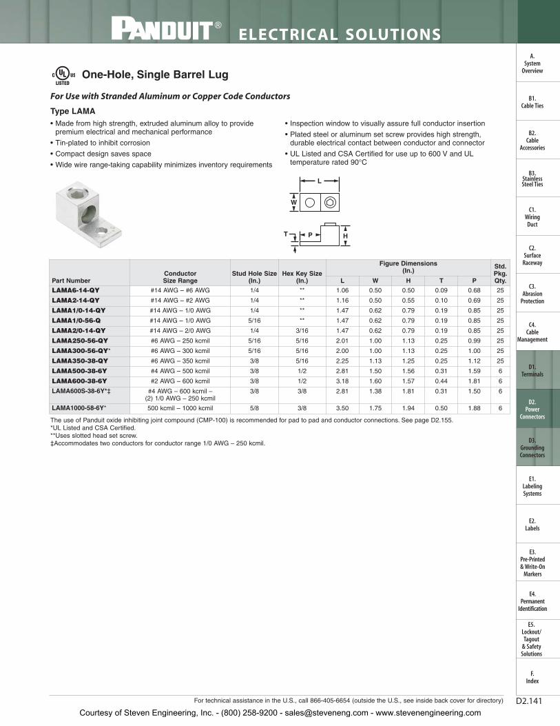
For technical assistance in the U.S., call 866-405-6654 (outside the U.S., see inside back cover for directory)
ELECTRICAL SOLUTIONS
D2.141
B2.Cable
Accessories
C1.Wiring
Duct
C3.Abrasion
Protection
C4.Cable
Management
D1.Terminals
D2.Power
Connectors
E1.LabelingSystems
E2.Labels
E3.Pre-Printed & Write-On
Markers
F.Index
B3.StainlessSteel Ties
C2.Surface
Raceway
E5.Lockout/Tagout
& SafetySolutions
B1.Cable Ties
A.System
Overview
D3.GroundingConnectors
E4.Permanent
Identification
One-Hole, Single Barrel Lug
• Made from high strength, extruded aluminum alloy to providepremium electrical and mechanical performance
• Tin-plated to inhibit corrosion
• Compact design saves space
• Wide wire range-taking capability minimizes inventory requirements
• Inspection window to visually assure full conductor insertion
• Plated steel or aluminum set screw provides high strength, durable electrical contact between conductor and connector
• UL Listed and CSA Certified for use up to 600 V and ULtemperature rated 90°C
For Use with Stranded Aluminum or Copper Code Conductors
Type LAMA
W
T P
L
H
The use of Panduit oxide inhibiting joint compound (CMP-100) is recommended for pad to pad and conductor connections. See page D2.155.*UL Listed and CSA Certified.**Uses slotted head set screw.‡Accommodates two conductors for conductor range 1/0 AWG – 250 kcmil.
Part NumberConductor Size Range
Stud Hole Size(In.)
Hex Key Size(In.)
Figure Dimensions (In.)
Std.Pkg.Qty.L W H T P
LAMA6-14-QY #14 AWG – #6 AWG 1/4 ** 1.06 0.50 0.50 0.09 0.68 25
LAMA2-14-QY #14 AWG – #2 AWG 1/4 ** 1.16 0.50 0.55 0.10 0.69 25
LAMA1/0-14-QY #14 AWG – 1/0 AWG 1/4 ** 1.47 0.62 0.79 0.19 0.85 25
LAMA1/0-56-Q #14 AWG – 1/0 AWG 5/16 ** 1.47 0.62 0.79 0.19 0.85 25
LAMA2/0-14-QY #14 AWG – 2/0 AWG 1/4 3/16 1.47 0.62 0.79 0.19 0.85 25
LAMA250-56-QY #6 AWG – 250 kcmil 5/16 5/16 2.01 1.00 1.13 0.25 0.99 25
LAMA300-56-QY* #6 AWG – 300 kcmil 5/16 5/16 2.00 1.00 1.13 0.25 1.00 25
LAMA350-38-QY #6 AWG – 350 kcmil 3/8 5/16 2.25 1.13 1.25 0.25 1.12 25
LAMA500-38-6Y #4 AWG – 500 kcmil 3/8 1/2 2.81 1.50 1.56 0.31 1.59 6
LAMA600-38-6Y #2 AWG – 600 kcmil 3/8 1/2 3.18 1.60 1.57 0.44 1.81 6
LAMA600S-38-6Y*‡ #4 AWG – 600 kcmil –(2) 1/0 AWG – 250 kcmil
3/8 3/8 2.81 1.38 1.81 0.31 1.50 6
LAMA1000-58-6Y* 500 kcmil – 1000 kcmil 5/8 3/8 3.50 1.75 1.94 0.50 1.88 6
Courtesy of Steven Engineering, Inc. - (800) 258-9200 - [email protected] - www.stevenengineering.com
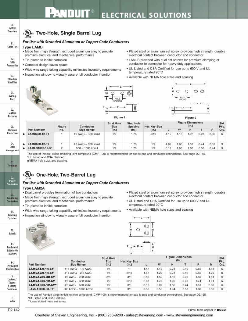
ELECTRICAL SOLUTIONS
Prime items appear in BOLD.D2.142
B2.Cable
Accessories
C1.Wiring
Duct
C3.Abrasion
Protection
C4.Cable
Management
D1.Terminals
D2.Power
Connectors
E1.LabelingSystems
E2.Labels
E3.Pre-Printed & Write-On
Markers
F.Index
B3.StainlessSteel Ties
C2.Surface
Raceway
E5.Lockout/Tagout
& SafetySolutions
B1.Cable Ties
A.System
Overview
D3.GroundingConnectors
E4.Permanent
Identification
Two-Hole, Single Barrel Lug
One-Hole, Two-Barrel Lug
• Made from high strength, extruded aluminum alloy to providepremium electrical and mechanical performance
• Tin-plated to inhibit corrosion
• Compact design saves space
• Wide wire range-taking capability minimizes inventory requirements
• Inspection window to visually assure full conductor insertion
• Plated steel or aluminum set screw provides high strength, durableelectrical contact between conductor and connector
• LAMLB provided with dual set screws for premium clamping ofconductor to connector for heavy duty applications
• UL Listed and CSA Certified for use up to 600 V and ULtemperature rated 90°C
• Available with NEMA hole sizes and spacing
For Use with Stranded Aluminum or Copper Code ConductorsType LAMB
The use of Panduit oxide inhibiting joint compound (CMP-100) is recommended for pad to pad and conductor connections. See page D2.155.*UL Listed and CSA Certified.**Uses slotted head set screw.
W
HOLESPACING
L
T P H
• Dual barrel provides termination of two conductors
• Made from high strength, extruded aluminum alloy to providepremium electrical and mechanical performance
• Tin-plated to inhibit corrosion
• Wide wire range-taking capability minimizes inventory requirements
• Inspection window to visually assure full conductor insertion
• Plated steel or aluminum set screw provides high strength, durableelectrical contact between conductor and connector
• UL Listed and CSA Certified for use up to 600 V and ULtemperature rated 90°C
• Available with NEMA hole sizes and spacing
W M
HT P
L
For Use with Stranded Aluminum or Copper Code ConductorsType LAM2A
W
L
HOLESPACING
T P H
Figure 1 Figure 2
The use of Panduit oxide inhibiting joint compound (CMP-100) is recommended for pad to pad and conductor connections. See page D2.155.*UL Listed and CSA Certified.uNEMA hole sizes and spacing.
Part NumberFigure
No.Conductor Size Range
Stud HoleSize(In.)
Stud HoleSpacing
(In.)Hex Key Size
(In.)
Figure Dimensions (In.)
Std.Pkg.Qty.L W H T P
◆ LAMB350-12-6Y 1 #6 AWG – 350 kcmil 1/2 1.75 5/16 4.19 1.13 1.28 0.28 3.05 6
◆ LAMB600-12-3Y 1 #2 AWG – 600 kcmil 1/2 1.75 1/2 4.69 1.60 1.57 0.44 3.31 3
◆ LAMLB1000-12-3* 2 500 – 1000 kcmil 1/2 1.75 1/2 6.19 1.63 1.88 0.56 3.44 3
Part NumberConductor Size Range
Stud HoleSize(In.)
Hex Key Size(In.)
Figure Dimensions (In.)
Std.Pkg.Qty.L W H T P M
LAM2A1/0-14-6Y #14 AWG – 1/0 AWG 1/4 ** 1.47 1.13 0.78 0.19 0.85 1.13 6LAM2A2/0-14-6Y #14 AWG – 2/0 AWG 1/4 3/16 1.47 1.20 0.78 0.19 0.85 1.20 6LAM2A250-38-6Y #6 AWG – 250 kcmil 3/8 3/8 2.56 1.50 1.19 0.25 1.56 1.64 6LAM2A350-12-6Y #6 AWG – 350 kcmil 1/2 5/16 2.87 1.73 1.25 0.25 1.74 1.91 6LAM2A600-12-6Y** #2 AWG – 600 kcmil 1/2 3/8 3.19 2.00 1.56 0.44 1.81 2.38 6LAM2A1000-58-6Y* 500 kcmil – 1000 kcmil 5/8 3/8 3.50 3.50 1.94 0.50 1.88 3.50 6
Courtesy of Steven Engineering, Inc. - (800) 258-9200 - [email protected] - www.stevenengineering.com

For technical assistance in the U.S., call 866-405-6654 (outside the U.S., see inside back cover for directory)
ELECTRICAL SOLUTIONS
D2.143
B2.Cable
Accessories
C1.Wiring
Duct
C3.Abrasion
Protection
C4.Cable
Management
D1.Terminals
D2.Power
Connectors
E1.LabelingSystems
E2.Labels
E3.Pre-Printed & Write-On
Markers
F.Index
B3.StainlessSteel Ties
C2.Surface
Raceway
E5.Lockout/Tagout
& SafetySolutions
B1.Cable Ties
A.System
Overview
D3.GroundingConnectors
E4.Permanent
Identification
One-Hole, Vertical Two-Barrel Lug
Two-Hole, Two-Barrel Lug
• Dual barrel provides termination of two conductors
• Made from high strength, extruded aluminum alloy to providepremium electrical and mechanical performance
• Tin-plated to inhibit corrosion
• Wide wire range-taking capability minimizes inventory requirements
• Inspection window to visually assure full conductor insertion
• Plated steel or aluminum set screw provides high strength, durableelectrical contact between conductor and connector
• UL Listed and CSA Certified for use up to 600 V and ULtemperature rated 90°C
For Use with Stranded Aluminum or Copper Code Conductors
Type LAM2SA
L
W
T
PH2
H1
• Dual barrel provides termination of two conductors
• Made from high strength, extruded aluminum alloy to providepremium electrical and mechanical performance
• Tin-plated to inhibit corrosion
• Wide wire range-taking capability minimizes inventory requirements
• Inspection window to visually assure full conductor insertion
• Plated steel or aluminum set screw provides high strength, durableelectrical contact between conductor and connector
• LAM2LB connector provided with dual set screws for premiumclamping of conductor to connector for heavy duty applications
• UL Listed for use up to 600 V and temperature rated 90°C
• Available with NEMA hole sizes and spacing
For Use with Stranded Aluminum or Copper Code Conductors
Type LAM2B
LHOLE
SPACING
W
T P H
The use of Panduit oxide inhibiting joint compound (CMP-100) is recommended for pad to pad and conductor connections. See page D2.155.
HOLESPACING
L
W
P HT
Figure 1 Figure 2
The use of Panduit oxide inhibiting joint compound (CMP-100) is recommended for pad to pad and conductor connections. See page D2.155.*UL Listed and CSA Certified.◆NEMA hole sizes and spacing.
Part NumberConductor Size Range
Stud Hole Size(In.)
Hex Key Size(In.)
Figure Dimensions (In.)
Std.Pkg.Qty.L W H1 H2 T P
LAM2SA300-56-3 #6 AWG – 300 kcmil 5/16 5/16 3.00 1.00 2.00 1.25 0.50 1.00 3
Part NumberFigure
No.Conductor Size Range
Stud HoleSize(In.)
Stud HoleSpacing
(In.)
Hex KeySize(In.)
Figure Dimensions (In.)
Std.Pkg.Qty.L W H T P
◆ LAM2B350-12-3Y 1 #6 AWG – 350 kcmil 1/2 1.75 5/16 4.19 1.91 1.28 0.25 3.06 3
◆ LAM2LB600-12-3* 2 #2 AWG – 600 kcmil 1/2 1.75 3/8 5.50 2.85 1.50 0.38 3.25 3
◆ LAM2LB1000-12-3* 2 500 – 1000 kcmil 1/2 1.75 1/2 6.19 3.48 1.88 0.56 3.44 3
Courtesy of Steven Engineering, Inc. - (800) 258-9200 - [email protected] - www.stevenengineering.com

ELECTRICAL SOLUTIONS
Prime items appear in BOLD.D2.144
B2.Cable
Accessories
C1.Wiring
Duct
C3.Abrasion
Protection
C4.Cable
Management
D1.Terminals
D2.Power
Connectors
E1.LabelingSystems
E2.Labels
E3.Pre-Printed & Write-On
Markers
F.Index
B3.StainlessSteel Ties
C2.Surface
Raceway
E5.Lockout/Tagout
& SafetySolutions
B1.Cable Ties
A.System
Overview
D3.GroundingConnectors
E4.Permanent
Identification
Two-Hole, Vertical Two-Barrel Lug
Two-Hole, Three-Barrel Lug
• Dual barrel provides termination of two conductors
• Vertical configuration saves space
• Made from high strength, extruded aluminum alloy to providepremium electrical and mechanical performance
• Tin-plated to inhibit corrosion
• Wide wire range-taking capability minimizes inventory requirements
• Inspection window to visually assure full conductor insertion
• Plated steel or aluminum set screw provides high strength, durableelectrical contact between conductor and connector
• UL Listed and CSA Certified for use up to 600 V and ULtemperature rated 90°C
W
H2H1
HOLESPACING
L
T
P
For Use with Stranded Aluminum or Copper Code ConductorsType LAM2SB
• Triple barrel provides termination of three conductors
• Made from high strength, extruded aluminum alloy to providepremium electrical and mechanical performance
• Tin-plated to inhibit corrosion
• Wide wire range-taking capability minimizes inventory requirements
• Inspection window to visually assure full conductor insertion
• Plated steel or aluminum set screw provides high strength, durableelectrical contact between conductor and connector
• LAM3LB connector is provided with dual set screws to allowpremium clamping of conductor to connector for heavy duty applications
• For use up to 600 V and temperature rated 90°C
• Available with NEMA hole sizes and spacing
T P
W
HOLESPACING
L
H
For Use with Stranded Aluminum or Copper Code ConductorsType LAM3B
W
HOLESPACING
P
T
L
H2
H1
Figure 1 Figure 2
The use of Panduit oxide inhibiting joint compound (CMP-100) is recommended for pad to pad and conductor connections. See page D2.155.*UL Listed and CSA Certified.
LHOLE
SPACING
W
HT P
Figure 1 Figure 2
The use of Panduit oxide inhibiting joint compound (CMP-100) is recommended for pad to pad and conductor connections. See page D2.155.**Uses slotted head set screw.◆NEMA hole sizes and spacing.
Part NumberFigure
No. Conductor Size Range
Stud HoleSize(In.)
Stud HoleSpacing
(In.)
Hex KeySize(In.)
Figure Dimensions (In.)
Std.Pkg.Qty.L W H1 H2 T P
LAM2SB600-38-1Y* 1 #2 AWG – 600 kcmil 3/8 1.38 3/8 4.91 1.50 3.00 1.88 0.75 2.34 1
LAM2SB750-38-1Y* 1 1/0 AWG – 750 kcmil 3/8 1.38 3/8 4.91 1.50 3.00 1.88 0.75 2.34 1
LAM2SSB500-141Y 2 4/0 AWG – 500 kcmil 1/4 0.69 1/2 2.91 1.44 2.38 1.77 0.63 1.69 1
Part NumberFigure
No.Conductor Size Range
StudHole Size(In.)
Stud Hole Spacing
(In.)
Hex Key Size(In.)
Figure Dimensions (In.)
Std.Pkg.Qty.L W H T P
LAM3B1/0-38-6Y 1 #14 AWG – 1/0 AWG 3/8 1.00 ** 2.91 2.00 0.88 0.25 2.16 6
◆ LAM3B3/0-12-3Y 1 #6 AWG – 3/0 AWG 1/2 1.75 1/4 4.25 2.81 1.19 0.31 3.25 3
◆ LAM3B250-12-1Y 1 #6 AWG – 250 kcmil 1/2 1.75 5/16 4.00 2.82 1.19 0.31 3.00 1
◆ LAM3B350-12-1Y 1 #6 AWG – 350 kcmil 1/2 1.75 5/16 4.50 3.50 1.38 0.31 3.25 1
◆ LAM3LB600-12-1 2 #2 AWG – 600 kcmil 1/2 1.75 3/8 5.50 4.32 1.50 0.38 3.25 1
◆ LAM3LB1000-121Y 2 500 kcmil – 1000 kcmil 1/2 1.75 1/2 6.19 5.27 1.88 0.56 3.44 1
Courtesy of Steven Engineering, Inc. - (800) 258-9200 - [email protected] - www.stevenengineering.com
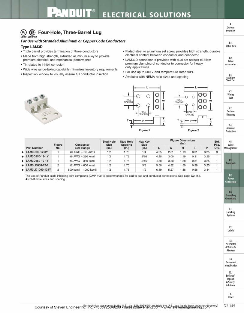
For technical assistance in the U.S., call 866-405-6654 (outside the U.S., see inside back cover for directory)
ELECTRICAL SOLUTIONS
D2.145
B2.Cable
Accessories
C1.Wiring
Duct
C3.Abrasion
Protection
C4.Cable
Management
D1.Terminals
D2.Power
Connectors
E1.LabelingSystems
E2.Labels
E3.Pre-Printed & Write-On
Markers
F.Index
B3.StainlessSteel Ties
C2.Surface
Raceway
E5.Lockout/Tagout
& SafetySolutions
B1.Cable Ties
A.System
Overview
D3.GroundingConnectors
E4.Permanent
Identification
• Triple barrel provides termination of three conductors
• Made from high strength, extruded aluminum alloy to providepremium electrical and mechanical performance
• Tin-plated to inhibit corrosion
• Wide wire range-taking capability minimizes inventory requirements
• Inspection window to visually assure full conductor insertion
• Plated steel or aluminum set screw provides high strength, durableelectrical contact between conductor and connector
• LAM3LD connector is provided with dual set screws to allowpremium clamping of conductor to connector for heavy duty applications
• For use up to 600 V and temperature rated 90°C
• Available with NEMA hole sizes and spacing
For Use with Stranded Aluminum or Copper Code Conductors
Type LAM3D
T H
HOLESPACING
L
W
P
HOLESPACING
The use of Panduit oxide inhibiting joint compound (CMP-100) is recommended for pad to pad and conductor connections. See page D2.155.◆NEMA hole sizes and spacing.
T P H
HOLESPACING
L
WHOLESPACING
Figure 1 Figure 2
Four-Hole, Three-Barrel Lug
Part NumberFigure
No.Conductor Size Range
Stud HoleSize(In.)
Stud HoleSpacing
(In.)
Hex KeySize(In.)
Figure Dimensions (In.)
Std.Pkg.Qty.L W H T P
◆ LAM3D3/0-12-3Y 1 #6 AWG – 3/0 AWG 1/2 1.75 1/4 4.25 2.81 1.19 0.31 3.25 3
◆ LAM3D250-12-1Y 1 #6 AWG – 250 kcmil 1/2 1.75 5/16 4.25 3.00 1.19 0.31 3.25 1
◆ LAM3D350-12-1Y 1 #6 AWG – 350 kcmil 1/2 1.75 5/16 4.50 3.50 1.38 0.31 3.25 1
◆ LAM3LD600-12-1 2 #2 AWG – 600 kcmil 1/2 1.75 3/8 5.50 4.32 1.50 0.38 3.25 1
◆ LAM3LD1000-121Y 2 500 kcmil – 1000 kcmil 1/2 1.75 1/2 6.19 5.27 1.88 0.56 3.44 1
Courtesy of Steven Engineering, Inc. - (800) 258-9200 - [email protected] - www.stevenengineering.com

ELECTRICAL SOLUTIONS
Prime items appear in BOLD.D2.146
B2.Cable
Accessories
C1.Wiring
Duct
C3.Abrasion
Protection
C4.Cable
Management
D1.Terminals
D2.Power
Connectors
E1.LabelingSystems
E2.Labels
E3.Pre-Printed & Write-On
Markers
F.Index
B3.StainlessSteel Ties
C2.Surface
Raceway
E5.Lockout/Tagout
& SafetySolutions
B1.Cable Ties
A.System
Overview
D3.GroundingConnectors
E4.Permanent
Identification
Two-Hole, Vertical Four-Barrel Lug
Four-Hole, Four-Barrel Lug
• Four barrels provide termination of four conductors
• Vertical configuration saves space
• Made from high strength, extruded aluminum alloy to provide premium electrical and mechanical performance
• Tin-plated to inhibit corrosion
• Wide wire range-taking capability minimizes inventory requirements
• Inspection window to visually assure full conductor insertion
• Plated steel or aluminum set screw provides high strength, durableelectrical contact between conductor and connector
• UL Listed and CSA Certified for use up to 600 V and ULtemperature rated 90°C
L
W
HOLESPACING
H2H1P
T
For Use with Stranded Aluminum or Copper Code Conductors
Type LAM4SB
• Four barrels provide termination of four conductors
• Made from high strength, extruded aluminum alloy to provide premium electrical and mechanical performance
• Tin-plated to inhibit corrosion
• Wide wire range-taking capability minimizes inventory requirements
• Inspection window to visually assure full conductor insertion
• Plated steel or aluminum set screw provides high strength, durable electrical contact between conductor and connector
• LAM4LD connector is provided with dual set screws to allowpremium clamping of conductor to connector for heavy duty applications
• For use up to 600 V and temperature rated 90°C
• Available with NEMA hole sizes and spacing
HOLESPACING
L
W
T HP
HOLESPACING
For Use with Stranded Aluminum or Copper Code Conductors
Type LAM4D
The use of Panduit oxide inhibiting joint compound (CMP-100) is recommended for pad to pad and conductor connections. See page D2.155.
W
L
PTH
HOLESPACING
HOLESPACING
The use of Panduit oxide inhibiting joint compound (CMP-100) is recommended for pad to pad and conductor connections. See page D2.155.◆NEMA hole sizes and spacing.
Figure 1 Figure 2
Part Number Conductor Size Range
Stud HoleSize(In.)
Stud HoleSpacing
(In.)
Hex Key Size(In.)
Figure Dimensions (In.)
Std.Pkg.Qty.L W H1 H2 T P
LAM4SB600-38-1Y #2 AWG – 600 kcmil 3/8 1.38 3/8 4.91 2.47 3.00 1.88 0.75 2.34 1
LAM4SB750-38-1Y 1/0 AWG – 750 kcmil 3/8 1.38 3/8 4.91 2.84 3.00 1.88 0.75 2.34 1
Part NumberFigure
No.Conductor Size Range
Stud HoleSize(In.)
Stud HoleSpacing
(In.)
Hex KeySize(In.)
Figure Dimensions (In.)
Std.Pkg.Qty.L W H T P
◆ LAM4D250-12-1Y 1 # 6 AWG – 250 kcmil 1/2 1.75 5/16 4.25 4.04 1.19 0.31 3.25 1
◆ LAM4D350-12-1Y 1 # 6 AWG – 350 kcmil 1/2 1.75 5/16 4.50 4.72 1.37 0.31 3.25 1
◆ LAM4LD600-12-1 2 #2 – 600 kcmil 1/2 1.75 3/8 5.50 5.31 1.50 0.38 3.25 1
◆ LAM4LD1000-12-1 2 350 – 1000 kcmil 1/2 1.75 3/8 6.19 7.11 1.88 0.56 3.44 1
Courtesy of Steven Engineering, Inc. - (800) 258-9200 - [email protected] - www.stevenengineering.com

For technical assistance in the U.S., call 866-405-6654 (outside the U.S., see inside back cover for directory)
ELECTRICAL SOLUTIONS
D2.147
B2.Cable
Accessories
C1.Wiring
Duct
C3.Abrasion
Protection
C4.Cable
Management
D1.Terminals
D2.Power
Connectors
E1.LabelingSystems
E2.Labels
E3.Pre-Printed & Write-On
Markers
F.Index
B3.StainlessSteel Ties
C2.Surface
Raceway
E5.Lockout/Tagout
& SafetySolutions
B1.Cable Ties
A.System
Overview
D3.GroundingConnectors
E4.Permanent
Identification
Part NumberTransformer KVA
Rating
AluminumMechanical Lug
Conductor Size Range
Hardware (Sizes in Inches)
Part No. Qty. Hex Bolt Size Qty. Nut Size Qty. Washer Size Qty.KLM14-250Y 15 – 37.5 KVA 1PH
15 – 45 KVA 3PHLAMA2-14
LAMA250-568 4
#14 – 2 AWG #6 AWG – 250 kcmil
1/4 – 20 x 3/4 HH 8 1/4 – 20 HN 8 1/4 FLAT 1/4 CMP
16 8
KLM6-250Y 50 – 75 KVA 1 PH 75 – 112.5 KVA 3 PH
LAMA250-56 12 #6 AWG – 250 kcmil 1/4 – 20 x 3/4 HH 1/4 – 20 x 2 HH
8 8
1/4 – 20 HN 16 1/4 FLAT 1/4 CMP
32 16
KLM6-600Y 100 – 167 KVA 1PH 150 – 300 KVA 3 PH
LAMA250-56 LAMA600-38
3 3
#6 AWG – 250 kcmil#4 AWG – 600 kcmil
1/4 – 20 x 3/4 HH 3/8 – 16 x 2 HH
3 16
1/4 – 20 HN 3/8 – 16 HN
316
3/8 FLAT 1/4 FLAT 3/8 CMP 1/4 CMP
326163
KLM6-800Y 100 – 167 KVA 1 PH 150 – 300 KVA 3 PH
LAM2A350-12 LAM2A800-58
6 7
#6 AWG – 350 kcmil 350 kcmil – 800 kcmil
1/2 – 13 x 2 HH 1/2 – 13 x 2 1/2 HH
5 6
1/2 – 13 HN 11 1/2 FLAT 1/2 CMP
2211
KLM350-800Y 500 KVA 3 PH LAM2A800-58 15 350 kcmil – 800 kcmil 1/2 – 13 x 2 HH 1/2 – 13 x 2 1/2 HH
7 4
1/2 – 13 HN 11 1/2 FLAT 1/2 CMP
2211
• Kits include all of the connectors and hardware to make acomplete transformer connection in a single convenient package
• Lugs are made from high strength, extruded aluminum alloy andare tin-plated to inhibit corrosion and oxidation
• Plated steel cap screws, belleville and flat washers, and hex nuts are provided to assure that terminal to bus connections are made using proper hardware resulting in true torque topressure performance
• Hardware is packaged in a sealed plastic bag to prevent losthardware prior to installation
• KLM6-800 and KLM350-800 kits include lugs that accommodate750 kcmil conductors used with large transformers
• Lugs are UL Listed and CSA Certified for use up to 600 V and ULtemperature rated 90°C
For Use with Stranded Aluminum or Copper Code Conductors
Type KLM
Transformer Lug Kit
Suffix: HH = Hex Head; HN = Hex Nut; FLAT = Flat Washer; CMP = Compression Washer.The use of Panduit oxide inhibiting joint compound (CMP-100) is recommended for pad to pad and conductor connections. See page D2.155.
Courtesy of Steven Engineering, Inc. - (800) 258-9200 - [email protected] - www.stevenengineering.com

ELECTRICAL SOLUTIONS
Prime items appear in BOLD.D2.148
B2.Cable
Accessories
C1.Wiring
Duct
C3.Abrasion
Protection
C4.Cable
Management
D1.Terminals
D2.Power
Connectors
E1.LabelingSystems
E2.Labels
E3.Pre-Printed & Write-On
Markers
F.Index
B3.StainlessSteel Ties
C2.Surface
Raceway
E5.Lockout/Tagout
& SafetySolutions
B1.Cable Ties
A.System
Overview
D3.GroundingConnectors
E4.Permanent
Identification
Splicer/Reducer
• Made from high strength extruded aluminum alloy to providepremium electrical and mechanical performance
• Tin-plated to inhibit corrosion
• Rounded bottoms to facilitate taping
• Solid center barrier prevents contact of dissimilar metal conductors
• Wide wire range-taking capability minimizes inventory requirements
• UL Listed and CSA Certified for use up to 600 V and ULtemperature rated 90°C
W
For Use with Stranded Aluminum or Copper Code Conductors
Type SR
The use of Panduit oxide inhibiting joint compound (CMP-100) is recommended. See page D2.155.**Uses slotted screws.
L
H
W
H
W
L
Figure 1 Figure 3Figure 2
H
L
Part Number Figure No.
Conductor Size RangeFigure Dimensions
(In.)Hex Key
Size(In.)
Std.Pkg.Qty.Max. Min. L W H
SR-2-XY 1 #2 AWG STR,#10 AWG SOL
#14 AWG STR,#14 AWG SOL
1.38 0.50 0.56 ** 10
SR-0-XY 1 1/0 AWG STR,#10 AWG SOL
#14 AWG STR,#14 AWG SOL
1.91 0.75 0.75 ** 10
SR-4/0-XY 1 4/0 AWG #6 AWG 2.31 1.00 1.13 5/16 10
SR-250-XY 2 250 kcmil #6 AWG 3.94 1.00 1.13 5/16 10
SR-350-XY 2 350 kcmil #6 AWG 4.19 1.13 1.19 5/16 10
SR-500-3Y 2 500 kcmil 3/0 AWG 5.00 1.37 1.40 3/8 3
SR-750-1Y 2 750 kcmil 250 kcmil 6.25 1.63 1.75 1/2 1
SR-1000-1Y 3 1000 kcmil 500 kcmil 8.69 1.72 1.88 9/16 1
Courtesy of Steven Engineering, Inc. - (800) 258-9200 - [email protected] - www.stevenengineering.com
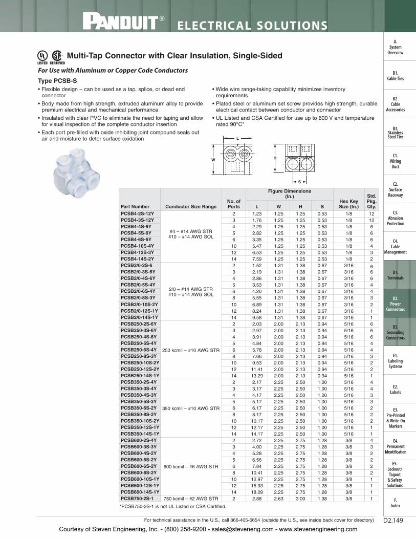
For technical assistance in the U.S., call 866-405-6654 (outside the U.S., see inside back cover for directory)
ELECTRICAL SOLUTIONS
D2.149
B2.Cable
Accessories
C1.Wiring
Duct
C3.Abrasion
Protection
C4.Cable
Management
D1.Terminals
D2.Power
Connectors
E1.LabelingSystems
E2.Labels
E3.Pre-Printed & Write-On
Markers
F.Index
B3.StainlessSteel Ties
C2.Surface
Raceway
E5.Lockout/Tagout
& SafetySolutions
B1.Cable Ties
A.System
Overview
D3.GroundingConnectors
E4.Permanent
Identification
Multi-Tap Connector with Clear Insulation, Single-Sided
• Flexible design – can be used as a tap, splice, or dead endconnector
• Body made from high strength, extruded aluminum alloy to providepremium electrical and mechanical performance
• Insulated with clear PVC to eliminate the need for taping and allowfor visual inspection of the complete conductor insertion
• Each port pre-filled with oxide inhibiting joint compound seals outair and moisture to deter surface oxidation
• Wide wire range-taking capability minimizes inventoryrequirements
• Plated steel or aluminum set screw provides high strength, durableelectrical contact between conductor and connector
• UL Listed and CSA Certified for use up to 600 V and temperaturerated 90°C*
For Use with Aluminum or Copper Code Conductors
Type PCSB-S
S
HW
L
*PCSB750-2S-1 is not UL Listed or CSA Certified.
Part Number Conductor Size RangeNo. ofPorts
Figure Dimensions (In.)
Hex Key Size (In.)
Std.Pkg.Qty.L W H S
PCSB4-2S-12Y
#4 – #14 AWG STR#10 – #14 AWG SOL
2 1.23 1.25 1.25 0.53 1/8 12PCSB4-3S-12Y 3 1.76 1.25 1.25 0.53 1/8 12PCSB4-4S-6Y 4 2.29 1.25 1.25 0.53 1/8 6PCSB4-5S-6Y 5 2.82 1.25 1.25 0.53 1/8 6PCSB4-6S-6Y 6 3.35 1.25 1.25 0.53 1/8 6PCSB4-10S-4Y 10 5.47 1.25 1.25 0.53 1/8 4PCSB4-12S-3Y 12 6.53 1.25 1.25 0.53 1/8 3PCSB4-14S-2Y 14 7.59 1.25 1.25 0.53 1/8 2PCSB2/0-2S-6
2/0 – #14 AWG STR#10 – #14 AWG SOL
2 1.52 1.31 1.38 0.67 3/16 6PCSB2/0-3S-6Y 3 2.19 1.31 1.38 0.67 3/16 6PCSB2/0-4S-6Y 4 2.86 1.31 1.38 0.67 3/16 6PCSB2/0-5S-4Y 5 3.53 1.31 1.38 0.67 3/16 4PCSB2/0-6S-4Y 6 4.20 1.31 1.38 0.67 3/16 4PCSB2/0-8S-3Y 8 5.55 1.31 1.38 0.67 3/16 3PCSB2/0-10S-2Y 10 6.89 1.31 1.38 0.67 3/16 2PCSB2/0-12S-1Y 12 8.24 1.31 1.38 0.67 3/16 1PCSB2/0-14S-1Y 14 9.58 1.31 1.38 0.67 3/16 1PCSB250-2S-6Y
250 kcmil – #10 AWG STR
2 2.03 2.00 2.13 0.94 5/16 6PCSB250-3S-6Y 3 2.97 2.00 2.13 0.94 5/16 6PCSB250-4S-6Y 4 3.91 2.00 2.13 0.94 5/16 6PCSB250-5S-4Y 5 4.84 2.00 2.13 0.94 5/16 4PCSB250-6S-4Y 6 5.78 2.00 2.13 0.94 5/16 4PCSB250-8S-3Y 8 7.66 2.00 2.13 0.94 5/16 3PCSB250-10S-2Y 10 9.53 2.00 2.13 0.94 5/16 2PCSB250-12S-2Y 12 11.41 2.00 2.13 0.94 5/16 2PCSB250-14S-1Y 14 13.29 2.00 2.13 0.94 5/16 1PCSB350-2S-4Y
350 kcmil – #10 AWG STR
2 2.17 2.25 2.50 1.00 5/16 4PCSB350-3S-4Y 3 3.17 2.25 2.50 1.00 5/16 4PCSB350-4S-3Y 4 4.17 2.25 2.50 1.00 5/16 3PCSB350-5S-3Y 5 5.17 2.25 2.50 1.00 5/16 3PCSB350-6S-2Y 6 6.17 2.25 2.50 1.00 5/16 2PCSB350-8S-2Y 8 8.17 2.25 2.50 1.00 5/16 2PCSB350-10S-2Y 10 10.17 2.25 2.50 1.00 5/16 2PCSB350-12S-1Y 12 12.17 2.25 2.50 1.00 5/16 1PCSB350-14S-1Y 14 14.17 2.25 2.50 1.00 5/16 1PCSB600-2S-4Y
600 kcmil – #6 AWG STR
2 2.72 2.25 2.75 1.28 3/8 4PCSB600-3S-3Y 3 4.00 2.25 2.75 1.28 3/8 3PCSB600-4S-2Y 4 5.28 2.25 2.75 1.28 3/8 2PCSB600-5S-2Y 5 6.56 2.25 2.75 1.28 3/8 2PCSB600-6S-2Y 6 7.84 2.25 2.75 1.28 3/8 2PCSB600-8S-2Y 8 10.41 2.25 2.75 1.28 3/8 2PCSB600-10S-1Y 10 12.97 2.25 2.75 1.28 3/8 1PCSB600-12S-1Y 12 15.93 2.25 2.75 1.28 3/8 1PCSB600-14S-1Y 14 18.09 2.25 2.75 1.28 3/8 1PCSB750-2S-1 750 kcmil – #2 AWG STR 2 2.88 2.63 3.00 1.38 3/8 1
Courtesy of Steven Engineering, Inc. - (800) 258-9200 - [email protected] - www.stevenengineering.com

ELECTRICAL SOLUTIONS
Prime items appear in BOLD.D2.150
B2.Cable
Accessories
C1.Wiring
Duct
C3.Abrasion
Protection
C4.Cable
Management
D1.Terminals
D2.Power
Connectors
E1.LabelingSystems
E2.Labels
E3.Pre-Printed & Write-On
Markers
F.Index
B3.StainlessSteel Ties
C2.Surface
Raceway
E5.Lockout/Tagout
& SafetySolutions
B1.Cable Ties
A.System
Overview
D3.GroundingConnectors
E4.Permanent
Identification
Multi-Tap Connector with Clear Insulation, Double-Sided
• Flexible design – can be used as a tap, splice, or dead end connector
• Body made from high strength, extruded aluminum alloy to provide premium electrical and mechanical performance
• Insulated with clear PVC to eliminate the need for taping and allow for visual inspection of the complete conductor insertion
• Each port pre-filled with oxide inhibiting joint compound seals out air and moisture to deter surface oxidation
• Wide wire range-taking capability minimizes inventory requirements
• Dual-sided entry allows offset and opposite entry for primary andsecondary conductors
• Plated steel or aluminum set screw provides high strength, durableelectrical contact between conductor and connector
• UL Listed and CSA Certified for use up to 600 V and temperaturerated 90°C
W
L
For Use with Aluminum or Copper Code Conductors
Type PCSB
‡‡Not UL Listed or CSA Certified.
S
H
Part Number Conductor Size Range No. of Ports
Figure Dimensions (In.) Hex Key
Size (In.)
Std.Pkg.Qty.L W H S
PCSB4-2-12Y
#4 – #14 AWG STR #10 – #14 AWG SOL
2 1.23 1.50 1.25 0.53 1/8 12
PCSB4-3-12Y 3 1.76 1.50 1.25 0.53 1/8 12
PCSB4-4-6Y 4 2.29 1.50 1.25 0.53 1/8 6
PCSB4-5-6Y 5 2.82 1.50 1.25 0.53 1/8 6
PCSB4-6-6Y 6 3.35 1.50 1.25 0.53 1/8 6
PCSB4-8-4Y 8 4.41 1.50 1.25 0.53 1/8 4
PCSB4-10-4Y 10 5.47 1.50 1.25 0.53 1/8 4
PCSB4-12-3Y 12 6.53 1.50 1.25 0.53 1/8 3
PCSB4-14-2Y 14 7.59 1.50 1.25 0.53 1/8 2
PCSB2/0-2-12
2/0 – #14 AWG STR #10 – #14 AWG SOL
2 1.52 1.56 1.38 0.67 3/16 12
PCSB2/0-3-6 3 2.19 1.56 1.38 0.67 3/16 6
PCSB2/0-4-6 4 2.86 1.56 1.38 0.67 3/16 6
PCSB2/0-5-6 5 3.53 1.56 1.38 0.67 3/16 6
PCSB2/0-6-6 6 4.20 1.56 1.38 0.67 3/16 6
PCSB2/0-8-4 8 5.55 1.56 1.38 0.67 3/16 4
PCSB2/0-10-2Y 10 6.89 1.56 1.38 0.67 3/16 2PCSB2/0-12-2Y 12 8.24 1.56 1.38 0.67 3/16 2PCSB2/0-14-1Y 14 9.58 1.56 1.38 0.67 3/16 1
PCSB250-2-6Y
250 kcmil – #10 AWG STR
2 2.03 2.63 2.13 0.94 5/16 6
PCSB250-3-6Y 3 2.97 2.63 2.13 0.94 5/16 6
PCSB250-4-6Y 4 3.91 2.63 2.13 0.94 5/16 6
PCSB250-5-4Y 5 4.84 2.63 2.13 0.94 5/16 4
PCSB250-6-4Y 6 5.78 2.63 2.13 0.94 5/16 4
PCSB250-8-3Y 8 7.66 2.63 2.13 0.94 5/16 3
PCSB250-10-2Y 10 9.53 2.63 2.13 0.94 5/16 2
PCSB250-12-2Y 12 11.41 2.63 2.13 0.94 5/16 2
PCSB250-14-1Y 14 13.29 2.63 2.13 0.94 5/16 1
Courtesy of Steven Engineering, Inc. - (800) 258-9200 - [email protected] - www.stevenengineering.com

SHWL
Std.Pkg.Qty.
Hex KeySize (In.)
Figure Dimensions (In.)
No. of PortsConductor Size RangePart Number
For technical assistance in the U.S., call 866-405-6654 (outside the U.S., see inside back cover for directory)
ELECTRICAL SOLUTIONS
D2.151
B2.Cable
Accessories
C1.Wiring
Duct
C3.Abrasion
Protection
C4.Cable
Management
D1.Terminals
D2.Power
Connectors
E1.LabelingSystems
E2.Labels
E3.Pre-Printed & Write-On
Markers
F.Index
B3.StainlessSteel Ties
C2.Surface
Raceway
E5.Lockout/Tagout
& SafetySolutions
B1.Cable Ties
A.System
Overview
D3.GroundingConnectors
E4.Permanent
Identification
Multi-Tap Connector with Clear Insulation, Double-Sided (continued)
‡‡Not UL Listed or CSA Certified.
PCSB350-2-4
350 kcmil – #10 AWG STR#10 AWG SOL
2 2.17 3.00 2.50 1.00 3/8 4
PCSB350-3-4 3 3.17 3.00 2.50 1.00 3/8 4
PCSB350-4-3 4 4.17 3.00 2.50 1.00 3/8 3
PCSB350-5-3 5 5.17 3.00 2.50 1.00 3/8 3
PCSB350-6-2 6 6.17 3.00 2.50 1.00 3/8 2
PCSB350-8-2 8 8.17 3.00 2.50 1.00 3/8 2
PCSB350-10-2Y 10 10.17 3.00 2.50 1.00 5/16 2
PCSB350-12-1Y 12 12.17 3.00 2.50 1.00 5/16 1
PCSB350-14-1Y 14 14.17 3.00 2.50 1.00 5/16 1
PCSB600-2-4Y
600 kcmil – #6 AWG STR
2 2.72 3.00 2.75 1.28 3/8 4
PCSB600-3-3Y 3 4.00 3.00 2.75 1.28 3/8 3
PCSB600-4-2Y 4 5.28 3.00 2.75 1.28 3/8 2
PCSB600-5-2 5 6.56 3.00 2.75 1.28 3/8 2
PCSB600-6-2Y 6 7.84 3.00 2.75 1.28 3/8 2
PCSB600-8-2Y 8 10.41 3.00 2.75 1.28 3/8 2
PCSB600-10-1Y 10 12.97 3.00 2.75 1.28 3/8 1
PCSB600-12-1Y 12 15.53 3.00 2.75 1.28 3/8 1
PCSB600-14-1Y 14 18.09 3.00 2.75 1.28 3/8 1
PCSB750-2-2Y‡‡
750 kcmil – #2 AWG STR
2 2.88 3.38 3.00 1.38 3/8 2
PCSB750-3-2Y‡‡ 3 4.25 3.38 3.00 1.38 3/8 2
PCSB750-4-2Y‡‡ 4 5.63 3.38 3.00 1.38 3/8 2
PCSB750-5-1Y‡‡ 5 7.00 3.38 3.00 1.38 3/8 1
PCSB750-6-1Y‡‡ 6 8.38 3.38 3.00 1.38 3/8 1
PCSB750-8-1Y‡‡ 8 11.13 3.38 3.00 1.38 3/8 1
PCSB750-10-1Y‡‡ 10 13.88 3.38 3.00 1.38 3/8 1
Courtesy of Steven Engineering, Inc. - (800) 258-9200 - [email protected] - www.stevenengineering.com

ELECTRICAL SOLUTIONS
Prime items appear in BOLD.D2.152
B2.Cable
Accessories
C1.Wiring
Duct
C3.Abrasion
Protection
C4.Cable
Management
D1.Terminals
D2.Power
Connectors
E1.LabelingSystems
E2.Labels
E3.Pre-Printed & Write-On
Markers
F.Index
B3.StainlessSteel Ties
C2.Surface
Raceway
E5.Lockout/Tagout
& SafetySolutions
B1.Cable Ties
A.System
Overview
D3.GroundingConnectors
E4.Permanent
Identification
In-Line Splicer/Reducer with Clear Insulation
• Flexible design – can be used as a splice or reducer
• Dual rated for use with copper or aluminum conductors
• Made from high strength, extruded aluminum alloy to provide premium electrical and mechanical performance
• Insulated with clear PVC to eliminate the need for taping and allow for visual inspection of the complete conductor insertion
• Each port pre-filled with oxide inhibiting joint compound seals out air and moisture to deter surface oxidation
• Wide wire range-taking capability minimizes inventory requirements
• Plated steel or aluminum set screw provides high strength, durableelectrical contact between conductor and connector
• UL Listed and CSA Certified for use up to 600 V and ULtemperature rated 90°C
W
L
H
For Use with Aluminum or Copper Code Conductors
Type PISR
Part Number Conductor Size Range
Figure Dimensions (In.)
Std.Pkg.Qty.L W H
PISR2-1 #2 AWG STR – #14 AWG STR,#8 AWG SOL – #10 AWG SOL
2.38 0.75 1.25 1
PISR1/0-1 1/0 AWG STR – #14 AWG STR, #8 AWG SOL – #14 AWG SOL
2.91 0.95 1.41 1
PISR250-1 250 kcmil – #10 AWG STR,#8 AWG SOL – #10 AWG SOL
4.00 1.25 2.24 1
PISR350-1 350 kcmil – #10 AWG STR,#8 AWG SOL – #10 AWG SOL
4.63 1.40 2.34 1
PISR500-1 500 kcmil – #6 AWG STR 5.25 1.72 2.63 1
Courtesy of Steven Engineering, Inc. - (800) 258-9200 - [email protected] - www.stevenengineering.com

For technical assistance in the U.S., call 866-405-6654 (outside the U.S., see inside back cover for directory)
ELECTRICAL SOLUTIONS
D2.153
B2.Cable
Accessories
C1.Wiring
Duct
C3.Abrasion
Protection
C4.Cable
Management
D1.Terminals
D2.Power
Connectors
E1.LabelingSystems
E2.Labels
E3.Pre-Printed & Write-On
Markers
F.Index
B3.StainlessSteel Ties
C2.Surface
Raceway
E5.Lockout/Tagout
& SafetySolutions
B1.Cable Ties
A.System
Overview
D3.GroundingConnectors
E4.Permanent
Identification
Multi-Tap Connector with Clear Insulation, Single-Sided, with Mounting Holes
• Flexible design – can be used as a tap, splice, or dead end connector
• Body made from high strength, extruded aluminum alloy to providepremium electrical and mechanical performance
• Two isolated mounting holes at either end of connector facilitatedirect mounting using 1/4'' bolts
• Insulated with clear PVC to eliminate the need for taping and allow for visual inspection of the complete conductor insertion
• Each port pre-filled with oxide inhibiting joint compound seals outair and moisture to deter surface oxidation
• Wide wire range-taking capability minimizes inventory requirements
• Plated steel or aluminum set screw provides high strength, durableelectrical contact between conductor and connector
• UL Listed and CSA Certified for use up to 600 V and temperaturerated 90°C
For Use with Aluminum or Copper Code Conductors
Type PCSBMT-S
S
H
W
M
L
Part Number Conductor Size RangeNo. ofPorts
Figure Dimensions (In.)
Mounting HoleSize (In.)
Hex Key Size (In.)
Std.Pkg.Qty.L W H S M
PCSBMT2/0-4S-3Y
2/0 – #14 AWG STR#10 – #14 AWG SOL
4 4.20 1.31 1.50 0.67 3.61 1/4 3/16 3PCSBMT2/0-6S-2Y 6 5.55 1.31 1.50 0.67 4.96 1/4 3/16 2PCSBMT2/0-8S-2Y 8 6.89 1.31 1.50 0.67 6.30 1/4 3/16 2PCSBMT2/0-10S2Y 10 8.24 1.31 1.50 0.67 7.65 1/4 3/16 2PCSBMT2/0-12S1Y 12 9.58 1.31 1.50 0.67 8.99 1/4 3/16 1PCSBMT250-4S-2Y
250 kcmil – #10 AWG STR
4 5.78 2.00 2.25 0.94 4.94 1/4 5/16 2PCSBMT250-6S-2Y 6 7.66 2.00 2.25 0.94 6.82 1/4 5/16 2PCSBMT250-8S-2Y 8 9.53 2.00 2.25 0.94 8.69 1/4 5/16 2PCSBMT250-10S2Y 10 11.41 2.00 2.25 0.94 10.57 1/4 5/16 2PCSBMT250-12S1Y 12 13.29 2.00 2.25 0.94 12.45 1/4 5/16 1PCSBMT350-4S-2Y
350 kcmil – #10 AWG STR
4 6.17 2.25 2.63 1.00 5.25 1/4 5/16 2PCSBMT350-6S-2Y 6 8.17 2.25 2.63 1.00 7.25 1/4 5/16 2PCSBMT350-8S-2Y 8 10.17 2.25 2.63 1.00 9.25 1/4 5/16 2PCSBMT350-10S1Y 10 12.17 2.25 2.63 1.00 11.25 1/4 5/16 1PCSBMT350-12S1Y 12 14.17 2.25 2.63 1.00 13.25 1/4 5/16 1PCSBMT600-4S-2Y
600 kcmil – #6 AWG STR
4 7.84 2.25 2.88 1.28 6.65 1/4 3/8 2PCSBMT600-6S-2Y 6 10.41 2.25 2.88 1.28 9.22 1/4 3/8 2PCSBMT600-8S-2Y 8 12.97 2.25 2.88 1.28 11.78 1/4 3/8 2PCSBMT600-10S1Y 10 15.53 2.25 2.88 1.28 14.34 1/4 3/8 1PCSBMT600-12S1Y 12 18.09 2.25 2.88 1.28 16.90 1/4 3/8 1
Courtesy of Steven Engineering, Inc. - (800) 258-9200 - [email protected] - www.stevenengineering.com

ELECTRICAL SOLUTIONS
Prime items appear in BOLD.D2.154
B2.Cable
Accessories
C1.Wiring
Duct
C3.Abrasion
Protection
C4.Cable
Management
D1.Terminals
D2.Power
Connectors
E1.LabelingSystems
E2.Labels
E3.Pre-Printed & Write-On
Markers
F.Index
B3.StainlessSteel Ties
C2.Surface
Raceway
E5.Lockout/Tagout
& SafetySolutions
B1.Cable Ties
A.System
Overview
D3.GroundingConnectors
E4.Permanent
Identification
Multi-Tap Connector with Clear Insulation, Double-Sided, with Mounting Holes
• Flexible design – can be used as a tap, splice, or dead end connector
• Body made from high strength, extruded aluminum alloy to providepremium electrical and mechanical performance
• Two isolated mounting holes at either end of connector facilitate direct mounting using 1/4" bolts
• Insulated with clear PVC to eliminate the need for taping and allow for visual inspection of the complete conductor insertion
• Each port pre-filled with oxide inhibiting joint compound seals outair and moisture to deter surface oxidation
• Wide wire range-taking capability minimizes inventory requirements
• Dual-sided entry allows offset and opposite entry for primary andsecondary conductors
• Plated steel or aluminum set screw provides high strength, durableelectrical contact between conductor and connector
• UL Listed and CSA Certified for use up to 600 V and temperaturerated 90°C
W
M
L
H
S
For Use with Aluminum or Copper Code Conductors
Type PCSBMT
Part Number Conductor Size RangeNo. ofPorts
Figure Dimensions (In.) Mounting HoleSize (In.)
Hex KeySize (In.)
Std.Pkg.Qty.L W H S M
PCSBMT2/0-4-3Y
2/0 – #14 AWG STR,#10 – #14 AWG SOL
4 4.20 1.56 1.50 0.67 3.61 1/4 3/16 3PCSBMT2/0-6-2Y 6 5.55 1.56 1.50 0.67 4.96 1/4 3/16 2PCSBMT2/0-8-2Y 8 6.89 1.56 1.50 0.67 6.30 1/4 3/16 2PCSBMT2/0-10-2Y 10 8.24 1.56 1.50 0.67 7.65 1/4 3/16 2PCSBMT2/0-12-1Y 12 9.58 1.56 1.50 0.67 8.99 1/4 3/16 1PCSBMT250-4-2Y
250 kcmil – #10 AWG STR
4 5.78 2.63 2.26 0.94 4.94 1/4 5/16 2PCSBMT250-6-2Y 6 7.66 2.63 2.26 0.94 6.82 1/4 5/16 2PCSBMT250-8-2Y 8 9.53 2.63 2.26 0.94 8.69 1/4 5/16 2PCSBMT250-10-2Y 10 11.41 2.63 2.26 0.94 10.57 1/4 5/16 2PCSBMT250-12-1Y 12 13.29 2.63 2.26 0.94 12.45 1/4 5/16 1PCSBMT350-4-2Y
350 kcmil – #10 AWG STR
4 6.17 3.00 2.63 1.00 5.25 1/4 5/16 2PCSBMT350-6-2Y 6 8.17 3.00 2.63 1.00 7.25 1/4 5/16 2PCSBMT350-8-2Y 8 10.17 3.00 2.63 1.00 9.25 1/4 5/16 2PCSBMT350-10-1Y 10 12.17 3.00 2.63 1.00 11.25 1/4 5/16 1PCSBMT350-12-1Y 12 14.17 3.00 2.63 1.00 13.25 1/4 5/16 1PCSBMT600-4-2Y
600 kcmil – #6 AWG STR
4 7.84 3.00 2.88 1.28 6.65 1/4 3/8 2PCSBMT600-6-2Y 6 10.41 3.00 2.88 1.28 9.22 1/4 3/8 2PCSBMT600-8-2Y 8 12.97 3.00 2.88 1.28 11.78 1/4 3/8 2PCSBMT600-10-1Y 10 15.53 3.00 2.88 1.28 14.34 1/4 3/8 1PCSBMT600-12-1Y 12 18.09 3.00 2.88 1.28 16.90 1/4 3/8 1
Courtesy of Steven Engineering, Inc. - (800) 258-9200 - [email protected] - www.stevenengineering.com

For technical assistance in the U.S., call 866-405-6654 (outside the U.S., see inside back cover for directory)
ELECTRICAL SOLUTIONS
D2.155
B2.Cable
Accessories
C1.Wiring
Duct
C3.Abrasion
Protection
C4.Cable
Management
D1.Terminals
D2.Power
Connectors
E1.LabelingSystems
E2.Labels
E3.Pre-Printed & Write-On
Markers
F.Index
B3.StainlessSteel Ties
C2.Surface
Raceway
E5.Lockout/Tagout
& SafetySolutions
B1.Cable Ties
A.System
Overview
D3.GroundingConnectors
E4.Permanent
Identification
Belleville Compression Washers
Part NumberStud Hole Size
(In.)
Figure Dimensions (In.)
Std.Pkg.Qty.D H T
CW-14-L 1/4 0.68 0.09 0.05 50
CW-56-L 5/16 0.81 0.08 0.06 50
CW-38-L 3/8 0.93 0.10 0.07 50
CW-12-Q 1/2 1.18 0.12 0.09 25
CW-58-Q 5/8 1.49 0.15 0.12 25
For Use with Aluminum Connectors
• Conical spring washer for use when assembling aluminumconnectors to copper and/or steel pads, compensates fordiffering rates of thermal expansion to keep hardwareassembly from loosening
• For assembly information, see page D2.158
• Made from hardened steel to provide high strength
• Cadmium-plated to inhibit corrosion
Type CW
D
T
H
• Oxide inhibitor for compression conductor connections lowerselectrical resistance of compression joint while sealing out air and moisture to prevent the formation of surface oxides
• Wide operating temperature range; can be used in a wide range of electrical and environmental conditions
• Packaged in convenient dispenser bottles
Type CMP
Part Number Description
Std.Pkg.Qty.
CMP-100-1 Contact aid for pad-to-pad or thread-to-thread aluminum connections, 8 oz. Operatingtemperature range -60°F (-51°C) to 400°F (204°C).
1
Joint Compounds
Courtesy of Steven Engineering, Inc. - (800) 258-9200 - [email protected] - www.stevenengineering.com

ELECTRICAL SOLUTIONS
D2.156
B2.Cable
Accessories
C1.Wiring
Duct
C3.Abrasion
Protection
C4.Cable
Management
D1.Terminals
D2.Power
Connectors
E1.LabelingSystems
E2.Labels
E3.Pre-Printed & Write-On
Markers
F.Index
B3.StainlessSteel Ties
C2.Surface
Raceway
E5.Lockout/Tagout
& SafetySolutions
B1.Cable Ties
A.System
Overview
D3.GroundingConnectors
E4.Permanent
Identification
Guidelines for Installing Aluminum Mechanical Connectors
1. Select the correct connector for your application.
• Always use an aluminum conductor with analuminum connector
• Verify that the connector is marked for the conductor size and type that you are using
2. Remove the insulation from insulated cable.
• See page D3.38 for Panduit cable stripping tools• Use care to avoid nicking the conductor strands• Strip the insulation to the proper length as listed in the
installation instructions provided with Panduit connectors
3. Clean the exposed conductor using a wire brush or anemery cloth.
• In a similar manner, clean an unplated connector pad and thesurface to which the connector will be attached
• Solvent should be used to clean plated parts that are dirty, but the plating should never be disturbed with abrasives
4. Apply Panduit joint compound to the clean conductor formechanical connector applications (see page D2.155).
• Joint compound will deter the formation of surface oxides after installation
• Aluminum compression connectors and insulated mechanical connectors are pre-filled with joint compound
5. Insert the conductor into the connector and:
• For mechanical connectors, tighten the screws to the recommended torque values
• For compression connectors, use the recommended die and crimping tool to make the proper compression connection
Courtesy of Steven Engineering, Inc. - (800) 258-9200 - [email protected] - www.stevenengineering.com

Logo (Symbol) Agency Spec/Approval Applicable Products
Underwriters Laboratories, Inc.
UL 486A-486BWire Connectors and
Soldering Lugsfor use in US and Canada
As shown on product pages.
Underwriters Laboratories, Inc.
UL 486A-486BWire Connectors and
Soldering Lugsfor use in US
As shown on product pages.
Underwriters Laboratories, Inc.
UL 486A-486BWire Connectors and
Soldering Lugsfor use in US
As shown on product pages.
Canadian StandardsAssociation
C22.2 No. 65-03Wire Connectors As shown on product pages.
American Bureauof Shipping
ABS RulesSteel Vessel Rules
1-1-4/7.7, 4-8-3/9.19,4-8-4/21.27
Copper compression connectorsLCA, LCAF, LCAS, LCAX, LCB, LCC, LCD, S-R,
LCDX, SCS, SCSF
NEBSLevel 3 Telcordia Technologies, Inc. Network Equipment –
Building Systems
Copper compression connectorsLCAS, LCA, LCD, LCB, LCC, LCAF, LCCF, SCSS,
SCS, SCL, SCSF
For technical assistance in the U.S., call 866-405-6654 (outside the U.S., see inside back cover for directory)
ELECTRICAL SOLUTIONS
D2.157
B2.Cable
Accessories
C1.Wiring
Duct
C3.Abrasion
Protection
C4.Cable
Management
D1.Terminals
D2.Power
Connectors
E1.LabelingSystems
E2.Labels
E3.Pre-Printed & Write-On
Markers
F.Index
B3.StainlessSteel Ties
C2.Surface
Raceway
E5.Lockout/Tagout
& SafetySolutions
B1.Cable Ties
A.System
Overview
D3.GroundingConnectors
E4.Permanent
Identification
Panduit Power Connector Approvals
Courtesy of Steven Engineering, Inc. - (800) 258-9200 - [email protected] - www.stevenengineering.com

ELECTRICAL SOLUTIONS
D2.158
B2.Cable
Accessories
C1.Wiring
Duct
C3.Abrasion
Protection
C4.Cable
Management
D1.Terminals
D2.Power
Connectors
E1.LabelingSystems
E2.Labels
E3.Pre-Printed & Write-On
Markers
F.Index
B3.StainlessSteel Ties
C2.Surface
Raceway
E5.Lockout/Tagout
& SafetySolutions
B1.Cable Ties
A.System
Overview
D3.GroundingConnectors
E4.Permanent
Identification
Copper to Copper Aluminum to Copper Aluminum to Aluminum Copper to Steel Aluminum to Steel
Recommended Termination Hardware
Recommended Hardware MaterialMaterial Configuration of Lug/Mounting Surface
1. Silicon bronze2. Stainless steel
1. Silicon bronze2. Aluminum3. Stainless steel
1. Aluminum2. Stainless steel3. Plated silicon bronze
1. Silicon bronze2. Stainless steel
1. Aluminum2. Stainless steel
Flashwasher
Copper or aluminumcompression ormechanical lug
Threaded stud
Busbar ormounting pad
Hex nut
Split lock washer orbelleville (conical) washerrecommended foraluminum lugs
Flat washer orbelleville (conical) washerrecommended foraluminum lugs
Use of CMP-100 jointcompound betweenaluminum lug andcopper or aluminumbusbar or mounting pad is recommended
Split lock washer
Hex nut
Split lock washer
Hex bolt or screw
Copper or aluminumcompression ormechanical lug
Busbar ormounting pad
Use of CMP-100 joint compoundbetween aluminum lug andcopper or aluminum busbar ormounting pad is recommended
Courtesy of Steven Engineering, Inc. - (800) 258-9200 - [email protected] - www.stevenengineering.com

For technical assistance in the U.S., call 866-405-6654 (outside the U.S., see inside back cover for directory)
ELECTRICAL SOLUTIONS
D2.159
B2.Cable
Accessories
C1.Wiring
Duct
C3.Abrasion
Protection
C4.Cable
Management
D1.Terminals
D2.Power
Connectors
E1.LabelingSystems
E2.Labels
E3.Pre-Printed & Write-On
Markers
F.Index
B3.StainlessSteel Ties
C2.Surface
Raceway
E5.Lockout/Tagout
& SafetySolutions
B1.Cable Ties
A.System
Overview
D3.GroundingConnectors
E4.Permanent
Identification
BBBBBBBBBBB
AAB&AAA
B&AAA
B&AAAAAB
A&A—B
A&A—B
A&A—B
A&A—B
AAAB
AAAB
AAAB
A&AAB
AAB&AAA
B&AA&AA
BBB
B&AAA
B&AAA
B&AAA
B&AAA
B&AB&A
Conductor Sizes
#20#18#16#14#12#10#9#8#7#6#5#4#4#3#3#2#2#1#1#11/01/01/02/02/02/03/03/03/04/04/04/0250250250300300300350350350400400450450500500600600700700750750800800900900100010001000
7777777777737373737197121971219712197121912193712193712193719371937193737613761376137613761376161
.036 /3
.045 /6
.057 /6
.072 /6
.091 /5.116.130.146.164.184.206.254.232.285.260.320.292.360.328.332.368.390.373.414.438.419.464.492.470.522.522.528.600.574.575.657.628.630.710.679.681.726.728.770.772.811.813.891.893.963.964.977.9981.0291.0311.0921.0941.1511.1521.152
Conductor SizeAWG or kcmil
Number ofStrands
NominalDiameter (In.) Class
Copper Concentric Stranded Conductor Sizes
41/.020149/.0184
133/.0111168/.010
37420/.006349/.020652/.0201
133/.0125210/.010
—532/.006349/.023163/.0201
133/.0140266/.010
61665/.006349/.026084/.0201
133/.0158336/.010
—836/.006349/.0292
105/.0201133/.0177420/.010
1051064/.006349/.0328
133/.0199133/.0201532/.010
1251323/.006349/.0368
133/.0223161/.0201665/.010
1501666/.0063133/.0251210/.0201259/.018836/.010
2252107/.0063133/.0282259/.0202266/.02011064/.010
2752646/.0063133/.0316259/.0227342/.02011323/.010
3253325/.0063
IGHK
Locomotive (DLO)MGIHK
Locomotive (DLO)MGIHK
Locomotive (DLO)MGIHK
Locomotive (DLO)MGIHK
Locomotive (DLO)MGHIK
Locomotive (DLO)MGHIK
Locomotive (DLO)MGIHK
Locomotive (DLO)MGHIK
Locomotive (DLO)MGHIK
Locomotive (DLO)M
Conductor SizeAWG or kcmil
Number ofStrands
NominalDiameter (In.) Class
Flexible Copper Conductor Sizes
#8#8#8#8#8#8#7#7#7#7#7#7#6#6#6#6#6#6#5#5#5#5#5#5#4#4#4#4#4#4#3#3#3#3#3#3#2#2#2#2#2#2#1#1#1#1#1#11/01/01/01/01/01/02/02/02/02/02/02/0
.156
.166
.167
.157
.330
.162
.185
.185
.188
.179—
.196
.208
.207
.210
.210
.410
.215
.234
.235
.237
.235—
.240
.263
.263
.266
.272
.460
.269
.295
.299
.291
.304
.480
.305
.331
.335
.319
.338
.510
.337
.337
.367
.378
.397
.650
.376
.423
.424
.441
.451
.680
.423
.474
.477
.500
.470
.720
.508
Table continues on page D2.160
Courtesy of Steven Engineering, Inc. - (800) 258-9200 - [email protected] - www.stevenengineering.com
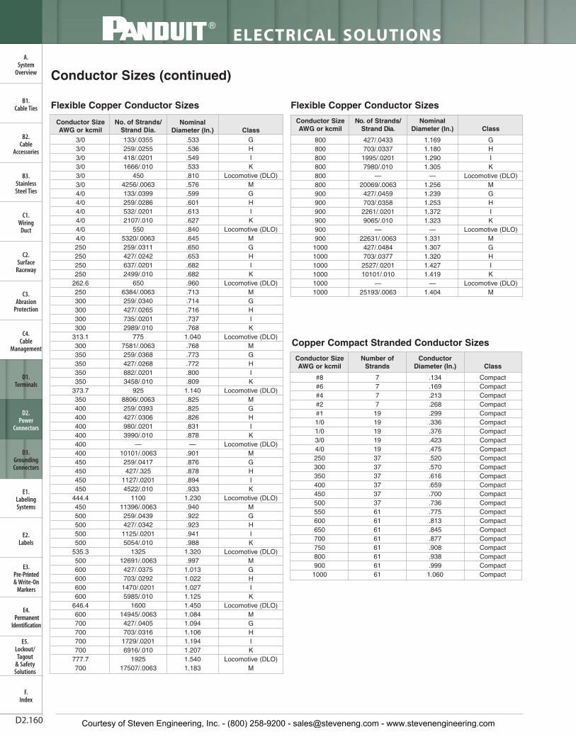
ELECTRICAL SOLUTIONS
D2.160
B2.Cable
Accessories
C1.Wiring
Duct
C3.Abrasion
Protection
C4.Cable
Management
D1.Terminals
D2.Power
Connectors
E1.LabelingSystems
E2.Labels
E3.Pre-Printed & Write-On
Markers
F.Index
B3.StainlessSteel Ties
C2.Surface
Raceway
E5.Lockout/Tagout
& SafetySolutions
B1.Cable Ties
A.System
Overview
D3.GroundingConnectors
E4.Permanent
Identification
Conductor Sizes (continued)
Flexible Copper Conductor Sizes
3/03/03/03/03/03/04/04/04/04/04/04/0250250250250
262.6250300300300300
313.1300350350350350
373.7350400400400400400400450450450450
444.4450500500500500
535.3500600600600600
646.4600700700700700
777.7700
133/.0355259/.0255418/.02011666/.010
4504256/.0063133/.0399259/.0286532/.02012107/.010
5505320/.0063259/.0311427/.0242637/.02012499/.010
6506384/.0063259/.0340427/.0265735/.02012989/.010
7757581/.0063259/.0368427/.0268882/.02013458/.010
9258806/.0063259/.0393427/.0306980/.02013990/.010
—10101/.0063259/.0417427/.325
1127/.02014522/.010
110011396/.0063
259/.0439427/.03421125/.02015054/.010
132512691/.0063
427/.0375703/.02921470/.02015985/.010
160014945/.0063
427/.0405703/.03161729/.02016916/.010
192517507/.0063
GHIK
Locomotive (DLO)MGHIK
Locomotive (DLO)MGHIK
Locomotive (DLO)MGHIK
Locomotive (DLO)MGHIK
Locomotive (DLO)MGHIK
Locomotive (DLO)MGHIK
Locomotive (DLO)MGHIK
Locomotive (DLO)MGHIK
Locomotive (DLO)MGHIK
Locomotive (DLO)M
Conductor SizeAWG or kcmil
No. of Strands/Strand Dia.
NominalDiameter (In.) Class
CompactCompactCompactCompactCompactCompactCompactCompactCompactCompactCompactCompactCompactCompactCompactCompactCompactCompactCompactCompactCompactCompactCompact
#8#6#4#2#11/01/03/04/0250300350400450500550600650700750800900
1000
7777
19191919193737373737376161616161616161
Conductor SizeAWG or kcmil
Number ofStrands
ConductorDiameter (In.) Class
Copper Compact Stranded Conductor Sizes
Flexible Copper Conductor Sizes
800800800800800800900900900900900900
100010001000100010001000
427/.0433703/.0337
1995/.02017980/.010
—20069/.0063427/.0459703/.0358
2261/.02019065/.010
—22631/.0063427/.0484703/.0377
2527/.020110101/.010
—25193/.0063
1.1691.1801.2901.305
—1.2561.2391.2531.3721.323
—1.3311.3071.3201.4271.419
—1.404
GHIK
Locomotive (DLO)MGHIK
Locomotive (DLO)MGHIK
Locomotive (DLO)M
Conductor SizeAWG or kcmil
No. of Strands/Strand Dia.
NominalDiameter (In.) Class
.134
.169
.213
.268
.299
.336
.376
.423
.475
.520
.570
.616
.659
.700
.736
.775
.813
.845
.877
.908
.938
.9991.060
.533
.536
.549
.533
.810
.576
.599
.601
.613
.627
.840
.645
.650
.653
.682
.682
.960
.713
.714
.716
.737
.7681.040.768.773.772.800.8091.140.825.825.826.831.878—
.901
.876
.878
.894
.9331.230.940.922.923.941.9881.320.9971.0131.0221.0271.1251.4501.0841.0941.1061.1941.2071.5401.183
Courtesy of Steven Engineering, Inc. - (800) 258-9200 - [email protected] - www.stevenengineering.com

For technical assistance in the U.S., call 866-405-6654 (outside the U.S., see inside back cover for directory)
ELECTRICAL SOLUTIONS
D2.161
B2.Cable
Accessories
C1.Wiring
Duct
C3.Abrasion
Protection
C4.Cable
Management
D1.Terminals
D2.Power
Connectors
E1.LabelingSystems
E2.Labels
E3.Pre-Printed & Write-On
Markers
F.Index
B3.StainlessSteel Ties
C2.Surface
Raceway
E5.Lockout/Tagout
& SafetySolutions
B1.Cable Ties
A.System
Overview
D3.GroundingConnectors
E4.Permanent
Identification
#8#7#6#5#4#3#2#11/02/03/04/02503003504004505005506006507007508009001000
777777719191919193737373737376161616161616161
48.654.561.268.877.286.797.466.474.583.794.0105.582.290.097.3104.0110.3116.295.099.2103.2107.1110.9114.5121.5128.0
Number ofStrands
Diameter of each
Strand (Mils)
Aluminum Concentric StrandedConductor Sizes
Class BAluminumConcentric
AWG or kcmil
Conductor Sizes (continued)
#18#17#16#15#14#13#12#11#10#9#8#7#6#5#4#3#2#11/02/03/04/0
.040
.045
.050
.057
.064
.071
.080
.090
.101
.114
.128
.128
.162
.181
.204
.229
.257
.289
.324
.364
.409
.460
Solid CopperConductor SizeAWG or kcmil
ConductorDiameter
(In.)
Copper Solid Conductor Sizes
.134
.169
.213
.238
.268
.299
.299
.336
.336
.376
.376
.423
.423
.475
.475
.520
.520
.520
.337
.337
.570
.570
.570
.603
.603
.616
.616
.659
.659
.700
.722
.736
.736
.775
.780
.813
.845
.877
.908
.938
.9991.060
#8#6#4#3#2#1#11/01/02/02/03/03/04/04/0250250250266266300300300336336350350397400450477500500550556600650700750800900
1000
A, BA, BA, BA, B
AA, A, BAA, A
BAA, A
BAA, A
BAA, A
BAA, A
BAAAB
AAA
AAAB
AAAAB
AA, ABB
AAAABB
AABBBBBBB
777777
197
197
197
197
197
19377
197
19377
191937193737191937611961616161616161
ClassASTMB400
Number ofStrands
ConductorDiameter
(In.)
Aluminum Compact Stranded Conductor Sizes
CompactAluminum
AWG or kcmil
Courtesy of Steven Engineering, Inc. - (800) 258-9200 - [email protected] - www.stevenengineering.com

AWG to Metric Wire CrossesAWG Metric (mm²)26 – 22 0.1 – 0.522 – 18 0.5 – 1.016 – 14 1.5 – 2.512 – 10 4.0 – 6.0
ELECTRICAL SOLUTIONS
D2.162
B2.Cable
Accessories
C1.Wiring
Duct
C3.Abrasion
Protection
C4.Cable
Management
D1.Terminals
D2.Power
Connectors
E1.LabelingSystems
E2.Labels
E3.Pre-Printed & Write-On
Markers
F.Index
B3.StainlessSteel Ties
C2.Surface
Raceway
E5.Lockout/Tagout
& SafetySolutions
B1.Cable Ties
A.System
Overview
D3.GroundingConnectors
E4.Permanent
Identification
Conductor
Individual Strands Overall Conductor Size
Conductor
Individual Strands Overall Conductor Size
No.
Diameter Diameter Area
No.
Diameter Diameter Area
AWGMetricmm2 mm In. mm In.
Circ.MILS AWG
Metricmm2 mm In. mm In.
Circ.MILS
.05 25 .05 .002 .25 .010 97
1.0
19 0.25 .010 1.30 .051 1841
.06 41 .05 .002 .36 .014 159 1 1.13 .044 1.13 .044 1979
26
10 .13 .005 .53 .021 250 32 .20 .008 1.30 .051 1984
1 .41 .016 .41 .016 256 7 .43 .017 1.30 .051 2006
7 .16 .006 .48 .019 278
16
19 .29 .011 1.47 .058 2426
19 .10 .004 .51 .020 304 65 .16 .006 1.50 .059 2580
24
41 .08 .003 .58 .023 384 *26 .25 .010 1.50 .059 2600
10 .16 .006 .58 .023 397 1 1.30 .051 1.30 .051 2601
1 .51 .020 .51 .020 400 105 .13 .005 1.50 .059 2625
7 .20 .008 .61 .024 448 *7 .51 .020 1.52 .060 2828
19 .13 .005 .61 .024 475
1.5
30 .25 .010 1.70 .067 2906
0.25
65 .07 .003 .65 .026 484 21 .30 .012 1.60 .063 2930
128 .05 .002 .65 .026 496 189 .10 .004 1.90 .075 2930
32 .10 .004 .65 .026 496 7 .52 .020 1.60 .063 2934
14 .16 .006 .65 .026 556 1 1.38 .054 1.38 .054 2952
22
1 .64 .025 .64 .025 625
14
45 .16 .006 1.85 .073 3786
16 .16 .006 .76 .030 635 19 .38 .014 1.85 .073 3831
26 .13 .005 .76 .030 650 1 1.63 .064 1.63 .064 4096
7 .25 .010 .76 .030 700 *41 .25 .010 1.85 .073 4100
19 .16 .006 .79 .031 754 *7 .64 .025 1.85 .073 4481
0.38
48 .10 .004 .80 .031 744
2.5
50 .25 .010 2.20 .087 4844
194 .05 .002 .80 .031 752 7 .67 .026 2.10 .083 4871
100 .07 .003 .80 .031 760 35 .30 .012 2.20 .087 4883
7 .27 .011 .80 .031 791 315 .10 .004 2.20 .087 4883
12 .21 .008 .80 .031 820 1 1.78 .070 1.78 .070 4911
21 .16 .006 .80 .031 833
12
19 .45 .018 2.36 .093 6088
.5
7 .30 .012 .90 .035 977 *65 .25 .010 2.41 .095 6500
16 .20 .008 .90 .035 992 165 .16 .006 2.41 .095 6549
1 .80 .031 .80 .031 992 1 2.06 .081 2.06 .081 6561
20
*10 .25 .010 .89 .035 1000 *7 .81 .032 2.44 .096 7168
1 .81 .032 .81 .032 1024
4.0
56 .30 .012 3.10 .122 7812
41 .13 .005 .91 .036 1025 1 2.26 .089 2.26 .089 7917
26 .16 .006 91 .036 1032 511 .10 .004 3.00 .118 7921
*7 .32 .013 .97 .038 1111 19 .52 .020 2.70 .106 7963
19 .20 .008 .94 .037 1216
10
37 .40 .016 2.92 .115 9354
.75
7 .37 .015 1.10 .043 1485 49 .36 .014 2.95 .116 9880
24 .20 .008 1.20 .047 1488 *7 .98 .039 2.95 .116 10376
1 1.00 .039 1.00 .039 1550 1 2.59 .102 2.59 .102 10404
18
*16 .25 .010 1.19 0.047 1600 *105 .25 .010 2.95 .116 10500
1 1.02 .040 1.02 .040 1600
6.0
84 .30 .012 3.50 .138 11718
65 .13 .005 1.19 .047 1625 756 .10 .004 3.70 .146 11718
41 .16 .006 1.19 .047 1627 1 2.76 .109 2.76 .109 11807
*7 .40 .016 1.22 .048 1770 7 1.05 .041 3.20 .126 11962
19 .25 .010 1.24 .049 1900 19 .64 .025 3.30 .130 12063
This chart details the different conductors commonly used in the industry.For each size, either AWG or Metric, various stranding options are listed.Typically the higher stranding is used in applications requiring greaterconductor flexibility.
Common Conductor Sizes and Strandings Reference Chart
*Strandings required for UL and CSA Certification testing.
Courtesy of Steven Engineering, Inc. - (800) 258-9200 - [email protected] - www.stevenengineering.com

For technical assistance in the U.S., call 866-405-6654 (outside the U.S., see inside back cover for directory)
ELECTRICAL SOLUTIONS
D2.163
B2.Cable
Accessories
C1.Wiring
Duct
C3.Abrasion
Protection
C4.Cable
Management
D1.Terminals
D2.Power
Connectors
E1.LabelingSystems
E2.Labels
E3.Pre-Printed & Write-On
Markers
F.Index
B3.StainlessSteel Ties
C2.Surface
Raceway
E5.Lockout/Tagout
& SafetySolutions
B1.Cable Ties
A.System
Overview
D3.GroundingConnectors
E4.Permanent
Identification
Conductor
Individual Strands Overall Conductor Size
Conductor
Individual Strands Overall Conductor Size
No.
Diameter Diameter Area
No.
Diameter Diameter Area
AWGMetricmm2 mm In. mm In.
Circ.MILS AWG
Metricmm2 mm In. mm In.
Circ.MILS
67 0.107 0.042 3.21 0.126 11840
9519 2.57 0.101 12.8 0.505 187500
1 2.77 0.109 2.77 0.109 11840 37 1.83 0.072 12.5 0.504 187500
97 1.1 0.0432 3.3 0.13 13000 4/0 19 2.89 0.1055 13.4 0.528 211600
1 2.91 0.1144 2.91 0.114 13090 120 37 2.06 0.081 14.4 0.567 237.8kcmil
81 3.26 0.1285 3.25 0.128 16510 250
kcmil 37 2.07 0.0822 14.6 0.575 250kcmil
7 1.23 0.0486 3.7 0.146 16510 300kcmil 150 37 2.29 0.09 16 0.63 300
kcmil
107 1.37 0.054 4.12 0.162 19740 350
kcmil 37 2.47 0.0973 17.3 0.681 350kcmil
1 3.58 0.141 3.58 0.141 19740 185 37 2.54 0.1 17.8 0.7 365.1kcmil
77 1.38 0.0545 4.15 0.164 20520 400
kcmil 37 2.64 0.104 18.5 0.728 400kcmil
1 3.67 0.1443 3.67 0.144 20520240
37 2.9 0.114 20.3 0.798 473.6kcmil
67 1.55 0.0612 4.66 0.184 26240 61 2.26 0.089 20.3 0.801 473.6
kcmil
1 4.11 0.162 4.11 0.162 26240500
kcmil
37 2.95 0.1162 20.7 0.813 500kcmil
16 7 1.73 0.008 5.13 0.204 31580 61 2.3 0.0905 20.7 0.814 500kcmil
5 7 1.75 0.0688 5.24 0.206 33090 300kcmil 61 2.51 0.099 22.6 0.891 592.1
kcmil
4 7 1.96 0.0772 5.88 0.232 41740 600kcmil 61 2.52 0.0992 22.7 0.893 600
kcmil
257 2.16 0.085 6.48 0.255 49340 700
kcmil 61 2.72 0.1071 24.5 0.964 700kcmil
19 1.32 0.052 6.6 0.26 49340750
kcmil
61 2.82 0.1109 25.4 0.998 750kcmil
3 7 2.2 0.0867 6.61 0.26 52620 91 2.31 0.0908 25.4 0.998 750kcmil
2 7 2.47 0.0974 7.42 0.292 66300 400 61 2.9 0.114 26.1 1.026 798.4kcmil
357 2.54 0.1 7.62 300 69070
800kcmil
61 2.91 0.1145 26.2 1.031 800kcmil
19 1.55 0.001 7.75 0.305 69070 91 2.38 0.0938 26.2 1.032 800kcmil
1 19 1.5 0.0064 8.43 0.332 836901000kcmil
500 61 3.25 0.128 28.3 1.152 986.8kcmil
50 19 1.85 0.073 9.27 0.365 98680 91 2.66 0.1048 29.3 1.153 1000kcmil
1/0 19 1.59 0.0745 9.46 0.373 10500 625 91 2.97 0.117 32.7 1.287 1233.7kcmil
2/0 19 2.13 0.0837 10.6 0.419 133100
70 19 2.18 0.086 10.9 0.43 138100
3/019 2.59 0.094 11.9 0.47 167800
36 1.71 0.0673 12 0.471 167800
Common Conductor Sizes and Strandings Reference Chart (continued)
Courtesy of Steven Engineering, Inc. - (800) 258-9200 - [email protected] - www.stevenengineering.com

ELECTRICAL SOLUTIONS
D2.164
B2.Cable
Accessories
C1.Wiring
Duct
C3.Abrasion
Protection
C4.Cable
Management
D1.Terminals
D2.Power
Connectors
E1.LabelingSystems
E2.Labels
E3.Pre-Printed & Write-On
Markers
F.Index
B3.StainlessSteel Ties
C2.Surface
Raceway
E5.Lockout/Tagout
& SafetySolutions
B1.Cable Ties
A.System
Overview
D3.GroundingConnectors
E4.Permanent
Identification
Equivalent TablesDecimal/Inches/Millimeters
Standard Stud Size #2 #4 #5 #6 #8 #10 1/4" 5/16" 3/8" 7/16"
Stud Size Decimal .086" .112" .127" .138" .164" .190" .250" .312" .375" .438"Equivalent
Terminal Hole Diameter .090" .118" .130" .147" .173" .204" .270" .343" .392"* .456".406"**
Stud Size Designation 2 4 5 6 8 10 14 56 38 76in Panduit Part Number
*Terminal stud.**Power Connector stud.
Standard Stud Size 1/2" 5/8" 3/4" 7/8" 1"
Stud Size Decimal .500" .625" .750" .875" 1.00"Equivalent
Terminal Hole Diameter .531" .656" .810" .906" 1.031"
Stud Size Designation 12 58 34 78 1in Panduit Part Number
Stud Size Chart (Inches/Millimeters)
Courtesy of Steven Engineering, Inc. - (800) 258-9200 - [email protected] - www.stevenengineering.com