a systems approach to understanding additive manufacturing
TRANSCRIPT

www.incose.org/glrc2018
A systems approach to understanding additive
manufacturing's impact on the aerospace supply chain
Advanced Manufacturing for Aerospace
Bill Bihlman, Bob Kenley, PhD., Gary Cheng, PhD.

www.incose.org/glrc2018 2
Part 1: AM Market Overview
Part 2: Aerospace Market Overview
Part 3: AM Process Modeling
Part 4: Case Study ~ Implementing AM
www.incose.org/glrc2018 3
Additive Manufacturing Overview
Part 1

All major aerospace companies have engaged
in some type of additive manufacturing (AM)
www.incose.org/glrc2018 4
Recent Investments in Additive
Source: secondary

AM enables building parts that historically were
not possible to machine
www.incose.org/glrc2018 5
AM is the process of adding - as opposed to removing - material to create a part
Overview to AM Process
Organic Shape Optimization Internal Lattice Optimization
Ultimate benefit is ability to lightweight a part,
known as topology optimization
Source: analysis

AM is categorized by material source and
energy method, clearly involving benefits/risks
www.incose.org/glrc2018 6
AM Characterization
Benefits
Reduce weight
Reduce part count
Reduce lead time
Increase material yield
Aerospace Applications
Repairs (1980s)
Tooling (1990s)
Whole parts (2010s)*
Classification
1) Material source:
Powder bed
Powder feed
Wire feed
2) Energy method:
Laser
Electron beam
Plasma
Risks
Microstructure quality
Process repeatability
* Mostly prototyping, not productionSource: analysis

Two most common AM “modalities” in
aerospace are powder bed and wire feed
www.incose.org/glrc2018 7
Powder bed favors engine (castings) parts, whereas wire
feed is for aerostructures (forgings)
Disadvantages: limited size, small batches,
source material control
Advantages: high near net, complex geometry
Growing layers via melting
powder metal – developed 1980s
for DARPA
Disadvantages: more machining, residual
stresses, voids/occlusions
Advantages: high deposition, economical
Melting wire – similar to welding
– to create molten pool to build
linear layers
Powder Bed (Sintering) Wire Feed (Welding)
Predominate AM Technologies
Source: analysis, secondary

AM process, however, introduces variability
and thus risk into production process
www.incose.org/glrc2018 8Source: Herzog et al. 2016
AM Physical Process & Resulting Microstructure
AM is complex physics process
Extreme heating/cooling affect gain and
mechanical properties
Aerospace historically uses isotropic metals
Problems such as creep and fatigue are
initiated by grain boundaries

AM parts are economically attract for ‘smaller’
production runs
www.incose.org/glrc2018 9
Notional Marginal Cost Analysis – Traditional vs AM
Source: secondary
Molds (casting) and dies (forging) are
expensive and have long development times
Thus, economies for these tool/die are
realized over long production runs
AM parts are more attractive for short runs
Break-even depends upon myriad factors
clearly complicating a typical ROI study
0
2
4
6
8
10
12
14
Pro
du
ct
Co
st ($
)
Units
Traditional Mfg
Additive Mfg
Break-even
www.incose.org/glrc2018 10
Aerospace Market Overview
Part 2

Differences between aircraft and automotive
effectively define their manufacturing strategies
www.incose.org/glrc2018Source: analysis, secondary
Aerospace vs Automotive Industry
* commercial turbine aircraft
Units Produced: 5 thousand* 60 million
Unit Size: 100 to 200 ft² 5 x 15 ft
Part Count: 2.5 million 30 thousand
Design Objective: Airworthiness Crashworthiness
Quality Drivers: Product integrity Production integrity
Supplier Base: Oligopoly Globally competitive
10

Aerospace is unique in part due to lower
margins-of-safety due to weight constraints
www.incose.org/glrc2018 12
Margin of Safety
Design
Load
Margin
of Safety
Material
Strength
Aircraft designed with margin-of-safety
1.5 to 2 to minimize weight
Automotive uses 3, pressure vessels 4
This helps minimize fuel consumption
Thus aerospace has stringent quality
control and maintenance schedules
Source: analysis, secondary

FAA certification is costly/arduous to guarantee
six-sigma adherence to design and safety
www.incose.org/glrc2018 13
Aircraft Design Substantiation
Certification is process of substantiating both
aircraft design and production
Engineering proves structure can withstand
anticipated static and dynamic loads
Testing begins with material samples to identify
basic material properties
In certain cases, full-scale testing is required –
expensive both time and money
Source: FAA
www.incose.org/glrc2018 14
AM Process Modeling
Part 3

Conventional manufacturing requires numerous
steps - often includes manual assembly…
www.incose.org/glrc2018 15
Notional Conventional Manufacturing Scheme
Electr 3D
Model
Technician
CNC
Machine
Mill Stock
Detailed
Part
Scrap
Detailed
Part
Detailed
Part
Technician
Fasteners
Assembly
Information
Labor
Material
Capital
Approve
Final Part
Post procs
& Inspect
Low HighKEY:Source: analysis

…whereas, for “targeted” parts, AM machines
can make complex assemblies directly
www.incose.org/glrc2018 16
Electr 3D
Model
Technician
AM
Machine
Powder
Assembly
Information
Labor
Material
Capital
Approve
Final Part
Post
processing
Low HighKEY:
Inspect
Byproduct
Notional Additive Manufacturing Scheme
Source: analysis

Consequently, entire AM process needs to be
fully understood to ensure part integrity
www.incose.org/glrc2018 17
EQUIPMENT
Conformed Final Part
1
Calibration
Software
version
Machine
parameters
LABOR3
Training
Experience
Standards
INSPECTION5
Visual
MATERIAL2
Purity
POST PROCESSING4
Stress Relief
HIP (Hot Iso Press)
Documnt/
Pedigree
Digital
scan
Particle
distribution
Shelf lifeTraceability
Reuse
Heat Treat
Micro Polish
Process Control Parameters for AM
Source: analysis

Business case needs to consider tradeoffs of
production efficiency vs mechanical properties
www.incose.org/glrc2018 18
Hardware Optimization Hierarchy
Hardware
Characteristics
Mechanical
Performance
Specific
Strength
Specific
Stiffness
Durability
Fatigue &
Damage Tol
Corrosion
Resistance
Production
Design &
Develop
Concept Model
Manufacture
Machine Assemble
Analyze
Economic
Build Maintain
Labor Equipment
Materials
Source: analysis
The single most important consideration for AM
aerospace parts is integrity over the life of the asset
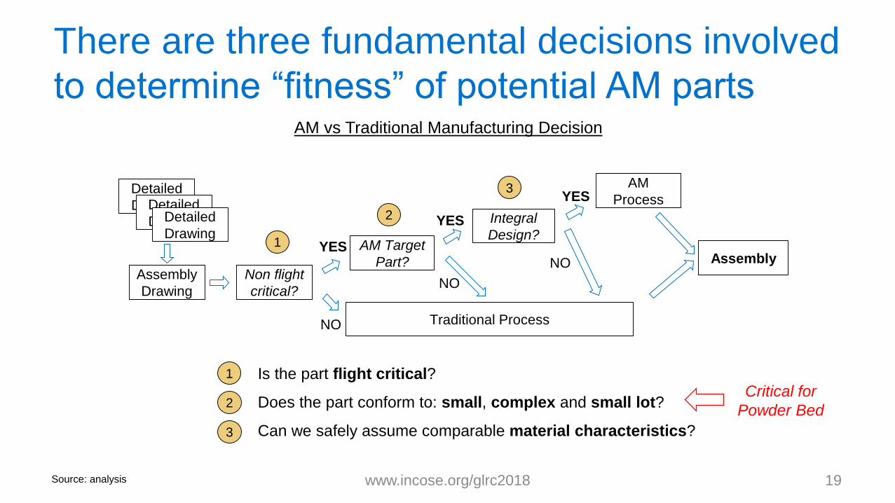
There are three fundamental decisions involved
to determine “fitness” of potential AM parts
www.incose.org/glrc2018 19
AM vs Traditional Manufacturing Decision
Assembly
Drawing
Integral
Design?
Assembly
Detailed
DrawingDetailed
DrawingDetailed
DrawingAM Target
Part?
Traditional Process
1
2
Non flight
critical?
YES
NO
YES
3
NO
1 Is the part flight critical?
Does the part conform to: small, complex and small lot?
Can we safely assume comparable material characteristics?
2
3
Source: analysis
Critical for
Powder Bed
YESAM
Process
NO

FAA currently lacks specific guidelines for AM part
qualification – most companies use “point design”
www.incose.org/glrc2018 20
AM Part Substantiation
Source: Jonas - NIAR, Gorelik - FAA
FAA 14 Code of Federal Regulations specifies new parts/process
be qualification based upon testing, including: 2X.603 (Materials),
2X.605 (Fabrication), and 2X.613 (Design Values)
However, FAA lacks formal guidance on AM parts – each applicant
must negotiate requirements directly via Special Condition
Most AM designs are “point design” and qualified by testing
MMPDS Emerging Technology Working Group is just beginning to
discuss AM requirements
Ultimate solution will likely incorporate: a) process controls, b)
damage tolerance framework, and c) sophisticated NDI methods

www.incose.org/glrc2018 21
Case Study: AM Implementation
Part 4

A simplified framework helps clarify elements
necessary for systems modeling
www.incose.org/glrc2018 22
ConversionMatter, Energy,
Information
FinishProduct
Processes
Rudimentary Process Schematic
Input Output
Constraints
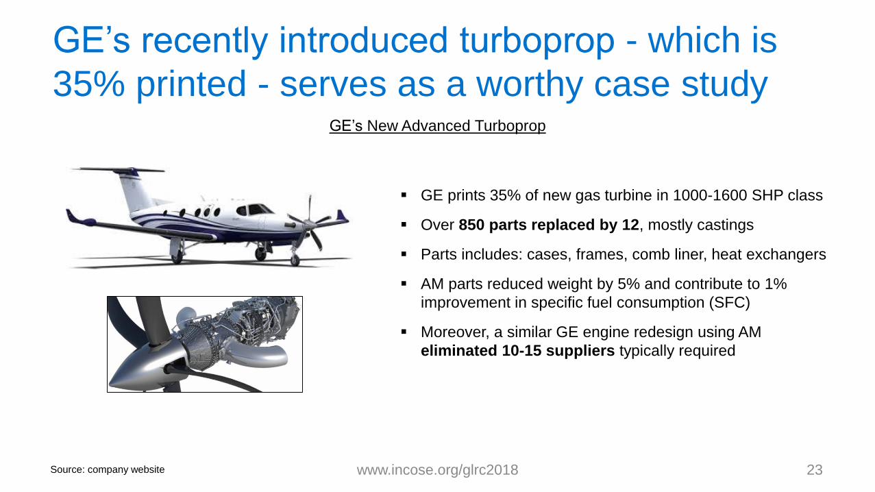
GE’s recently introduced turboprop - which is
35% printed - serves as a worthy case study
www.incose.org/glrc2018 23
GE prints 35% of new gas turbine in 1000-1600 SHP class
Over 850 parts replaced by 12, mostly castings
Parts includes: cases, frames, comb liner, heat exchangers
AM parts reduced weight by 5% and contribute to 1%
improvement in specific fuel consumption (SFC)
Moreover, a similar GE engine redesign using AM
eliminated 10-15 suppliers typically required
GE’s New Advanced Turboprop
Source: company website
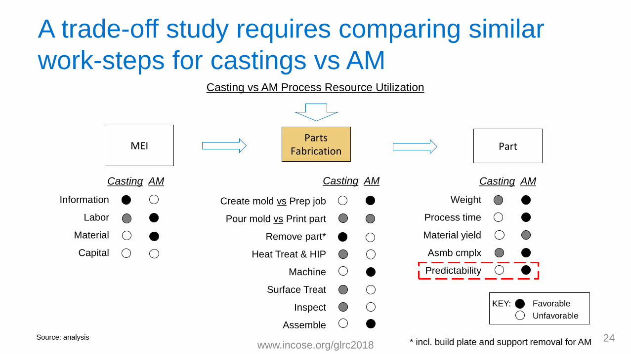
A trade-off study requires comparing similar
work-steps for castings vs AM
www.incose.org/glrc201824
Parts FabricationMEI Part
Favorable
Unfavorable
KEY:
Casting vs AM Process Resource Utilization
Casting AM
Information
Labor
Material
Capital
Casting AM
Weight
Process time
Material yield
Asmb cmplx
Predictability
Source: analysis* incl. build plate and support removal for AM
Create mold vs Prep job
Pour mold vs Print part
Remove part*
Heat Treat & HIP
Machine
Surface Treat
Inspect
Assemble
Casting AM

These steps then need to be compared in
terms of amount of processing time
www.incose.org/glrc2018 25Source: analysis, interviews
0
10
20
30
40
50
Casting AM
Assemble
Inspect
Surface Treat
Machine
Heat Treat & HIP
Remove part
Pour mold vs Print part
Create mold vs Prep job
For moderately complex castings, creating molds
can take from weeks to months
This step is the most variable and most time and
resource intensive of any process steps
For low volume production, AM parts can be
produced at least twice as fast as castings
Notional Time Per Work Step - Casting vs AM*
Da
ys
* Assumes CAD
model is available

AM’s adoption will likely considerably impact
casters and CNC machine shops
www.incose.org/glrc2018 26Source: analysis
Work Step
Conv Mfg
Process
AM
Process
Resource
Net Chng* Comments
Create mold vs
Prep jobCaster OEM 0.3 Significant negative impact to casters
Pour mold vs
Print partCaster OEM 0.8 Decrease in work requirements and need for special processes (i.e. hazmat)
Remove part Caster OEM 1.7 Will require establishing internal machining infrastructure and protocol
Heat Treat &
HIP 3rd party? OEM 1.2 Slight increase for market but shift from 3rd party to OEM
Machine 3rd party 3rd party? 0.3Significant negative impact to 3rd party CNC shops anticipated (and OEMs
may further control machining)
Surface Treat 3rd party? 3rd party? 1.4 Likely increase in surface treatment 3rd party work
Inspect OEM OEM 1.5 Increase unlikely to affect 3rd party market
Assemble OEM OEM 0.5 Decrease unlikely to affect 3rd party market
Supply Chain Impact of Conventional vs Additive Mfg
* Combination of
resource and time reqmt
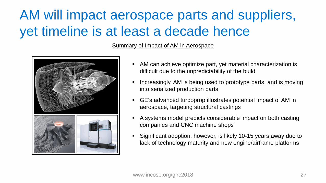
AM will impact aerospace parts and suppliers,
yet timeline is at least a decade hence
www.incose.org/glrc2018 27
AM can achieve optimize part, yet material characterization is
difficult due to the unpredictability of the build
Increasingly, AM is being used to prototype parts, and is moving
into serialized production parts
GE's advanced turboprop illustrates potential impact of AM in
aerospace, targeting structural castings
A systems model predicts considerable impact on both casting
companies and CNC machine shops
Significant adoption, however, is likely 10-15 years away due to
lack of technology maturity and new engine/airframe platforms
Summary of Impact of AM in Aerospace

www.incose.org/glrc2018