a traction-free model for the shizhen yin tensile stiffness and...
TRANSCRIPT

Shizhen YinState Key Laboratory of Nonlinear Mechanics,
Institute of Mechanics,Chinese Academy of Sciences,
Beijing 100190, China;School of Engineering Science,
University of Chinese Academy of Sciences,Beijing 100049, China
e-mail: [email protected]
Yewang Su1
State Key Laboratory of Nonlinear Mechanics,Institute of Mechanics,
Chinese Academy of Sciences,Beijing 100190, China;
School of Engineering Science,University of Chinese Academy of Sciences,
Beijing 100049, China;Beijing Key Laboratory of Engineered Construction
and Mechanobiology,Institute of Mechanics, Chinese Academy of
Sciences,Beijing 100190, China
e-mail: [email protected]
A Traction-Free Model for theTensile Stiffness and BendingStiffness of Laminated Ribbonsof Flexible ElectronicsLaminated ribbons have been widely adopted for structures of flexible electronics to simul-taneously achieve the electronic functions and mechanical performances. Their effectivetensile stiffness and bending stiffness, which are extensively used as fundamental parame-ters in the mechanical analysis, are usually obtained by the plane-strain hypothesis for sim-plicity. However, it is found that the practical condition is usually closer to the traction free,even for the cases with a relatively large width. Here, a traction-free model is proposed toanalytically obtain the effective tensile stiffness and bending stiffness of laminated ribbons,which can be used directly in the mechanical analysis of flexible electronics. The predictionof the traction-free model agrees very well with the precise result obtained by 3D finiteelement analysis (FEA) for the cases that are in the range of structure designs of flexibleelectronics. It is found that the tensile/bending stiffness of traction-free model is betweenthe plane-stress model and plane-strain model, but is closer to the plane-stress model.The use of the plane-strain model sometimes may yield a considerable error in the mechan-ical analysis of flexible electronics. The parameter study shows that this model is veryimportant for the problems with advanced materials, such as metamaterials with negativePoisson’s ratio. This work provides a theoretical basis for the mechanical analysis of flex-ible electronics. [DOI: 10.1115/1.4042920]
Keywords: laminated ribbon, tensile stiffness, bending stiffness, plane-strain, plane-stress,flexible electronics
1 IntroductionFlexible electronics have attracted increasing interest in the last
decade due to its great potential applications [1,2]. Examplesinclude electronic eye cameras [3], stretchable electronic skin [4–6],flexible health monitoring system [7–10], stretchable batteries [11],multifunctional integumentary cardiac membranes [12,13], piezo-electric energy harvesters [14–18], smart gloves for gesture recogni-tion, and smart clothing for sitting posturemonitoring [19].More andmore studies turn to practical applications [19–21] from ideal con-cepts of flexible electronics [22–27]. Compared with organicdevices, inorganic flexible electronicsmay achieve practical applica-tion earlier because of their high electronic performance and provenindustrial production lines.Mechanical structural designs, analysis, and optimization are crit-
ical for the flexibility and stretchability of inorganic electronics[28–30]. The most popular stretchable structure design is the island-bridge mesh structure, as shown in Fig. 1, in which the functionalcomponents reside on the islands and are connected by the stretch-able interconnects. The islands do not significantly deform, whilethe interconnects provide the stretchability for the entire system thatis subjected to apparently applied stretch. The geometric design ofthe interconnects (i.e., bridges) has been developed from straight[31,32] to curved [33–35] and fractal-inspired [11,21,36,37]layouts; the initial regime of the interconnects has been developedfrom two-dimensional [6] to three-dimensional configurations[38]; and the deformation mechanism has been developed from
buckling [39] to nonbuckling [20]. The stretchability can achieveas large as several hundred percent. For some applications thatdemand only the bendability rather than stretchability, thin-film-likestructures are widely adopted [14,17]. The thickness of the structureis the key of the design. According to mechanical analysis, thinnerstructures usually have better bendability while other parameters arekept constant.Laminated ribbons consisting of metals and polymers are widely
adopted to simultaneously realize the electronic functions andmechanical bendability and stretchability (Fig. 1) [39–41]. Theselaminated ribbons are usually subjected to loads of tension andbending. Their effective tensile stiffness and bending stiffness,which are frequently used as fundamental parameters in themechanical analysis, are usually obtained by the plane-strainhypothesis [14,15,17,39–44]. With this assumption, the strainalong the out-of-plane direction (x direction in Fig. 2(a)) is zerofor all layers. The reason for using the plane-strain hypothesis issometimes just for simplicity, or that the width of the ribbon is rel-atively large. However, the condition of the large width does notensure the condition of zero strain or zero stress in the x directionfor all layers. The practical condition in the out-of-plane directionis usually closer to that of the apparent traction force and moment(fx and mx in Fig. 2(a)) at the two edges perpendicular to the xaxis are zero, even for the cases with a relatively large width. There-fore, the mechanical condition is neither plane strain nor planestress, but should be apparently traction free. With the conditionof traction free, the interaction between each layer should be quan-titatively considered. The detailed analysis will be given in the fol-lowing Secs. 2 and 3.In this paper, a traction-free model that is different from both the
plane-strain model and the plane-stress model is developed toobtain the effective tensile stiffness and bending stiffness of lami-nated ribbons, which are frequently used in the mechanical analysis
1Corresponding author.Contributed by the Applied Mechanics Division of ASME for publication in the
JOURNAL OF APPLIED MECHANICS. Manuscript received January 26, 2019; final manu-script received February 17, 2019; published online March 16, 2019. Assoc. Editor:Yong Zhu.
Journal of Applied Mechanics MAY 2019, Vol. 86 / 051011-1Copyright © 2019 by ASME
of flexible electronic. In Sec. 2, the traction-free model is describedand analyzed. Effective tensile stiffness and bending stiffness areanalytically obtained. The plane-strain model and the plane-stressmodel are also analyzed for comparison. In Sec. 3, the traction-freemodel, the plane-strain model, and the plane-stress model are sys-tematically compared with a double-layer example. Finally, con-cluding remarks are given in Sec. 4.
2 Analytic Models for Laminated RibbonsIn this section, a traction-free model is proposed to analyze the
mechanical behaviors of laminated ribbons. The effective tensilestiffness and bending stiffness are analytically obtained by thismodel. As illustrated in Fig. 2(a), a laminated ribbon of n layersis subjected to the uniformly distributed axial forces fx and fzand bending moments mx and mz at the boundaries. The rela-tion between the thickness ti of each layer and the coordinate yi
is ti= yi− yi−1, as shown in Fig. 2(b). With the loads of tensionand bending, the principal strains are along the directions of thecoordinates. The strains can be obtained by the Kirchhoff assump-tion as
εx = εx0 + κx y −12
∑nj=1
tj
( )
εz = εz0 + κz y −12
∑nj=1
tj
( )⎧⎪⎪⎪⎪⎪⎨⎪⎪⎪⎪⎪⎩
(1)
where ɛx0 and ɛz0 are the membrane strain at the middle plane(y =
∑nj=1 tj/2) of the laminate ribbon along x and z directions
and κx and κz are the curvatures, respectively. It is worth notingthat the middle plane need not necessarily be the neutral planefor the laminated ribbons with multiple materials, i.e., ɛx0 and
(a) (b)
(c)
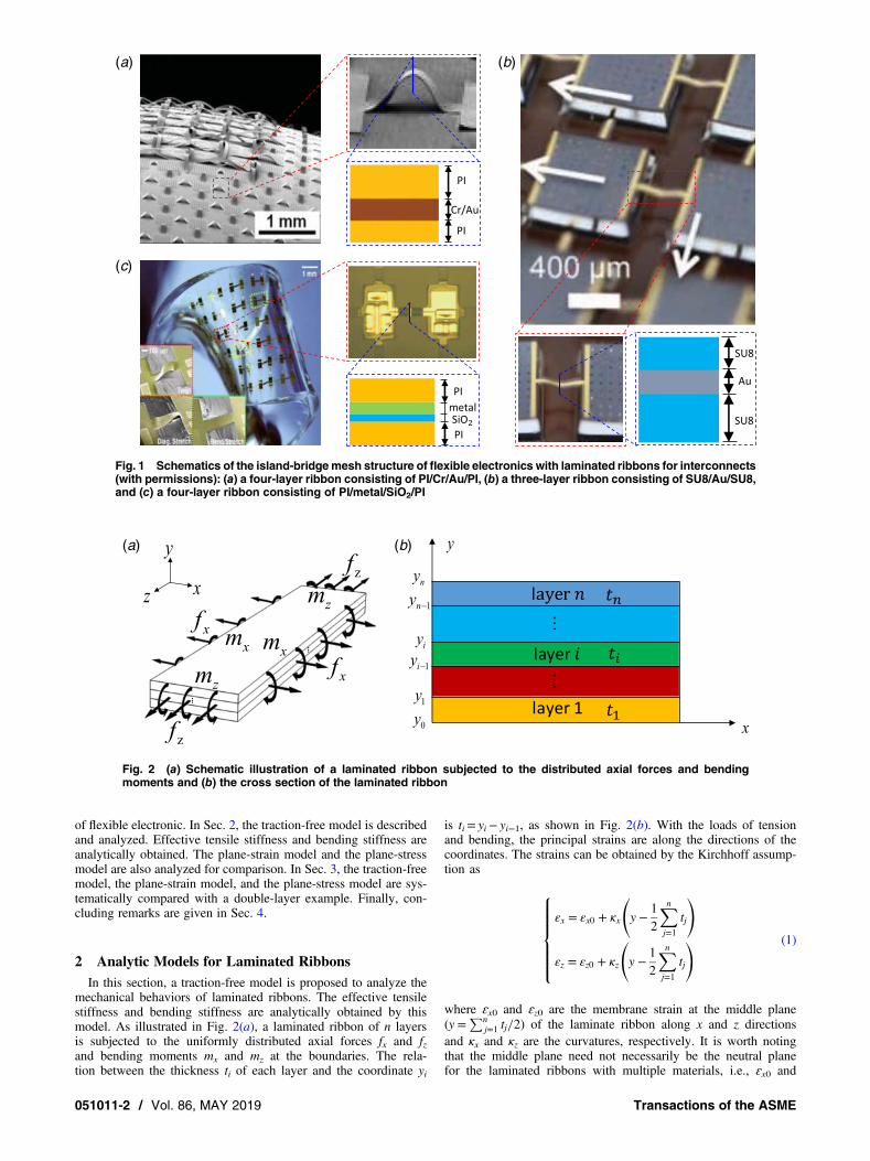
Fig. 1 Schematics of the island-bridgemesh structure of flexible electronics with laminated ribbons for interconnects(with permissions): (a) a four-layer ribbon consisting of PI/Cr/Au/PI, (b) a three-layer ribbon consisting of SU8/Au/SU8,and (c) a four-layer ribbon consisting of PI/metal/SiO2/PI
(a) (b)
Fig. 2 (a) Schematic illustration of a laminated ribbon subjected to the distributed axial forces and bendingmoments and (b) the cross section of the laminated ribbon
051011-2 / Vol. 86, MAY 2019 Transactions of the ASME

ɛz0 are not necessarily zero. The linear elastic constitutive relationgives the normal stresses as
σx =E
1 − ν2(εx + νεz)
σz =E
1 − ν2(εz + νεx)
⎧⎪⎨⎪⎩ (2)
Here, E is Young’s modulus and ν is Poisson’s ratio. Therefore,the axial forces and bending moments per unit length can beobtained by integration over the entire thickness of the laminatedribbons as follows:
fx =∫yny0
σxdy
fz =∫yny0
σzdy
mx =∫yny0
σx y −12
∑nj=1
tj
( )dy
mz =∫yny0
σz y −12
∑nj=1
tj
( )dy
(3)
Substitution of Eqs. (1) and (2) into Eq. (3) gives the relationbetween the axial forces/bending moments and the membranestrains/curvatures as
fxfzmx
mz
⎡⎢⎢⎣
⎤⎥⎥⎦ =
α1 α2 α3 α4α2 α1 α4 α3α3 α4 α5 α6α4 α3 α6 α5
⎡⎢⎢⎣
⎤⎥⎥⎦
εx0εz0κxκz
⎡⎢⎢⎣
⎤⎥⎥⎦ (4)
where
α1=∑ni=1
Eiti1−ν2i
α2=∑ni=1
νiEiti1−ν2i
α3=∑ni=1
Eiti2(1−ν2i )
(∑i−1j=1
tj+∑i
j=1
tj−∑nj=1
tj
)
α4=∑ni=1
νiEiti2(1−ν2i )
(∑i−1j=1
tj+∑i
j=1
tj−∑nj=1
tj
)
α5=∑ni=1
Ei
3(1−ν2i )
(∑i
j=1
tj−12
∑nj=1
tj
)3
−
(∑i−1j=1
tj−12
∑nj=1
tj
)3⎡⎣
⎤⎦
⎧⎨⎩
⎫⎬⎭
α6=∑ni=1
νiEi
3(1−ν2i )
(∑i
j=1
tj−12
∑nj=1
tj
)3
−
(∑i−1j=1
tj−12
∑nj=1
tj
)3⎡⎣
⎤⎦
⎧⎨⎩
⎫⎬⎭
(5)
Here, Ei, νi, and ti are Young’s modulus, Poisson’s ratio, andthe thickness of the ith layer in the laminated structure, respec-tively. With the traction-free condition at the boundaries that isperpendicular to the x axis
fx = mx = 0 (6)
and the zero bending moment condition
mz = 0 (7)
the tensile stiffness is obtained as
EAz,traction−free =fzεz0
=(α1α5 + α2α6 − α23 − α24)
2 − (α1α6 + α2α5 − 2α3α4)2
α1(α25 − α26) − α5(α23 + α24) + 2α3α4α6(8)
With the traction-free conditions (6) and the zero force condi-tion
fz = 0 (9)
the bending stiffness is obtained as
EIz,traction−free =mz
κz
=(α1α5 + α2α6 − α23 − α24)
2 − (α1α6 + α2α5 − 2α3α4)2
α5(α21 − α22) − α1(α23 + α24) + 2α2α3α4(10)
In the plane-strain model, εx = εx0 + κx y −∑n
j=1 tj/2( )
= 0 is
required. The traction-free model can be degenerated to the plane-strain model by applying the condition
εx0 = κx = 0 (11)
to the above derivations. In conventional derivation of plane-straintensile stiffness, the effect of bending is not considered. By apply-ing the additional condition κz= 0, the tensile stiffness of theplane-strain model can be obtained as
EAz,plane−strain = α1 =∑ni=1
Eiti1 − ν2i
(12)
With the traction-free condition (11), the bending stiffness thendegenerates to
EIz,plane−strain = α5 −α23α1
(13)
Replacing Ei/(1 − ν2i ) by Ei, in Eqs. (5), (12), and (13), thetensile stiffness and bending stiffness for the plane-stress modelare obtained as
EAz,plane−stress = α′1 =∑ni=1
Eiti (14)
and
EIz,plane−strain = α′5 −(α′3)
2
α′1(15)
where
α′1 =∑ni=1
Eiti
α′3 =∑ni=1
Eiti2
(∑i−1j=1
tj +∑i
j=1
tj −∑nj=1
tj
)
α′5 =∑ni=1
Ei
3
(∑i
j=1
tj −12
∑nj=1
tj
)3
−
(∑i−1j=1
tj −12
∑nj=1
tj
)3⎡⎣
⎤⎦
⎧⎨⎩
⎫⎬⎭(16)
Journal of Applied Mechanics MAY 2019, Vol. 86 / 051011-3

There are two special cases that should be discussed here:
(1) For νi= ν, Poisson’s ratio of each layer is the same. The coef-ficient αi in Eq. (5) degenerates to
α1 =1
1 − ν2α′1, α2 =
ν
1 − ν2α′1, α3 =
11 − ν2
α′3,
α4 =ν
1 − ν2α′3, α5 =
11 − ν2
α′5, α6 =ν
1 − ν2α′5
(17)
The bending stiffness of traction-free model given in Eq. (10)degenerates to Eq. (15) that is for the plane-stress model. Similarto the derivation of Eq. (8), the tensile stiffness of the traction-freemodel degenerates to Eq. (14) that is for the plane-stress model, bythe application of the additional condition κz= 0.
(1) For νi= 0, Poisson’s ratio of each layer is zero. The coeffi-cient αi in Eq. (5) degenerates to
α1 =1
1 − ν2α′1, α2 = 0, α3 =
11 − ν2
α′3,
α4 = 0, α5 =1
1 − ν2α′5, α6 = 0
(18)
The bending stiffness of the three models becomes exactly thesame. With the application of the additional condition κz= 0 tothe traction-free model, the tensile stiffness of the three modelsalso agrees with each other.
3 Results and DiscussionsIn this section, the traction-free model, the plane-strain model,
and the plane-stress model are compared systematically with anexample of a double-layer ribbon. The underlying mechanismthat yields the difference among the models is investigated.Effects of the parameters, such as the width of the ribbon,Young’s modulus, and Poisson’s ratio on the tensile stiffness andthe bending stiffness are studied comprehensively. Finite elementanalysis (FEA) with three-dimensional (3D) practical conditionsis conducted to verify the results.The cross section of the double-layer ribbon with width w, thick-
ness ti, Young’s modulus Ei, and Poisson’s ratio νi for the ith layer isshown in Fig. 3(a). To study the tensile stiffness, a uniformly dis-tributed tensile force fz is applied to the two ends of the ribbonwhile other forces and moments are zero (Fig. 2(a)). For thebending stiffness, a uniformly distributed bending moment mz isapplied to the two ends of the ribbon, while other forces andmoments are zero (Fig. 2(a)). With the thicknesses t1= t2= 1 μm,
(a)
(b1) (b2)
(c1) (c2)
Fig. 3 (a) Schematic illustration of the cross section of the double-layer ribbon. Comparison of the tensile/bending stiffness of the three models and 3D FEA, and the effects of the width: (b1) ν1===== 00000, ν2 ===== 0.49 for tensilestiffness, (b2) ν1 ===== 00000, ν2 ===== 00000.....4444499999 for bending stiffness, (c1) ν1 =====−−−−−0.9, ν2 ===== 0.49 for tensile stiffness, and(c2) ν1 =====−−−−−00000.....99999, ν2 =====00000.....49 for bending stiffness.
051011-4 / Vol. 86, MAY 2019 Transactions of the ASME

Young’s moduli E1=E2= 1 GPa and Poisson’s ratiosν1 = 0,ν2 = 0.49, the comparison of tensile/bending stiffness ofthe three models and the effects of the width w are depicted inFigs. 3(b1) and 3(b2), respectively. For all the ranges of thewidth w, the tensile/bending stiffness per width of the traction-freemodel is between that of the plane-stress model and the plane-strainmodel. The precise result predicted by FEA (see the next paragraphfor detail) verified the traction-free model. For w> 10 μm that is inthe range of structure designs of flexible electronics, the tensile/bending stiffness resulting from the traction-free model agreesvery well with the FEA prediction, while the precise resultapproaches the plane-stress model for the narrower width w. Fora small width w, the deformation mode of most regions does notfollow the Kirchhoff assumption, and the result of 3D FEA for prac-tical conditions deviates from the traction-free model andapproaches that of the plane-stress model. Moreover, the result ofthe traction-free model is closer to that of the plane-stress model,instead of the plane-strain model that has been usually adopted inthe past mechanical analysis for simplicity [14,15]. With the devel-opment of material science, metamaterials with extreme mechanicalproperties are widely utilized in advanced structures and devices. Inthis context, the case with ν1 = −0.9 and ν2 = 0.49 is studied inFigs. 3(c1) and 3(c2). The tensile/bending stiffness of the plane-strain model is more than three/two times as large as that of theplane-stress model, while the traction-free model is closer to theplane-stress model.In the model of FEA, the 3D solid element with real dimensions
and material parameters is used to simulate the practical conditions.The stress-free condition is applied at the two edges perpendicularto the x axis (Fig. 2(a)), as well as the bottom and top surfaces.Because the tensile/bending stiffness should be independent ofthe length of the model, the hypothesis of the plane section iskept at the two edges perpendicular to the z axis (Fig. 2(a)) byusing of the “reference point,” the “rigid plane,” and the “nonfric-tion contact” in the commercial software ABAQUS [45]. With
these conditions, the hypothesis of the plane section (x–y plane) iskept everywhere along the z axis, while the interaction betweenadjacent layers appears along the x axis.To understand the underlying mechanism that yields the differ-
ence among the three models, the distribution of the shear stressτxy at the interface between the two layers is studied with theexample of the tension of the double-layer ribbon. For the plane-strain model, there is no shear stress τxy at the interface betweenadjacent layers, which is ensured by the condition of zero strainɛxx for each layer. The “constraint” along the x direction is very“strong.” In the plane-stress model, the condition of zero stressσxx is confirmed, and the deformation in x direction is free and inde-pendent for each layer. Shear stress τxy is also zero or not consideredin fact. The “constraint” along the x direction is “zero.” In thetraction-free model, the condition of zero traction force andmoment is ensured anywhere along the x axis, while shear stressbetween the adjacent layers locates near the two boundaries asshown in Fig. 4. The “constraint” along the x direction is very“weak.” The order of the “constraint” of the three models corre-sponds to the order of the amplitude of the tensile stiffness, asshown in Figs. 3(b1), 3(b2), 3(c1), and 3(c2). Figure 4(a) showsthe distribution of the shear stress τxy normalized by the appliedstress σzz obtained by the 3D FEA with practical conditions. For asmall width (w< ∼3 μm), the shear stress distributes in the entirewidth and the peak is relatively small. The traction-free modelapproaches the plane-stress model, which is confirmed by the 3DFEA (Fig. 3). For a larger width (w> ∼3 μm), the nonzero shearstress distributes mainly at the area near the two boundaries. Thispoint is further shown in Fig. 4(b). The shear stress τxy transfersand balances the normal stress σxx of the two layers in a transferringregion with the size of rtransfer. When the width w reaches a certainlarge value, the peak of shear stress becomes a constant τmax, whichis independent of the width w. The transferring region rtransfer can bedefined as the size of the region where τxy/τmax ≥ 1%. As shown inFig. 4(b), rtransfer increases with the increase in the width w at the
(a)
(c)
(b)
Fig. 4 The distribution of the normalized shear stress at the interface between the two layers along thex axis: (a, b) ν1 ===== 00000 and (c) ν1 =====−−−−−00000.....99999
Journal of Applied Mechanics MAY 2019, Vol. 86 / 051011-5

beginning and becomes constant when w is large. For the extremecase with ν1 = −0.9 and ν2 = 0.49, the peaks of the shear stressbecomes much larger as depicted in Fig. 4(c) because the deforma-tion of the two layers becomes more uncoordinated.Furthermore, the effects of mechanical property and geometry on
the tensile/bending stiffness are also discussed for the three analyt-ical models. Firstly, the effect of Poisson’s ratio is studied as shownin Fig. 5. For the given Poisson’s ratio ν1=−0.9, 0, and 0.5, respec-tively, the tensile/bending stiffness as a function of ν2 is comparedwith those of the three models. The result of the plane-stress modelis independent of Poisson’s ratio ν1 and ν2. For ν1=−0.9, thetensile/bending stiffness of the plane-strain model is much largerthan that of the traction-free model and the plane-stress model(Figs. 5(a1) and 5(a2)). The result of the traction-free modelapproaches that of the plane-stress model for ν1= ν2=−0.9(Figs. 5(a1) and 5(a2)) and ν1= ν2= 0.5 (Figs. 5(c1) and 5(c2)),respectively. For ν1= 0 as shown in Figs. 5(b1) and 5(b2), theresults of the three models approach each other for ν2= 0. Theeffects of Young’s modulus E2 and thickness t2 are also studiedin Fig. 6. The tensile/bending stiffness here is normalized by thatof the plane-stress model. The results confirmed that the traction-free model can give an accurate prediction of the tensile/bendingstiffness for laminated ribbons of flexible electronics, while those
from the plane-strain model and the plane-stress model are notgood enough.
4 Concluding Remarks
(1) The effective tensile/bending stiffness of laminated ribbons,which is frequently used as the fundamental parameter in themechanical analysis of flexible electronics, is usuallyobtained by the plane-strain hypothesis for simplicity. It isfound that the practical condition is usually closer to the trac-tion free instead of the plane strain, even for the cases with arelatively large width.
(2) A traction-free model is proposed to study the effectivetensile/bending stiffness of the laminated ribbon. Analyticexpressions for the effective tensile/bending stiffness areobtained, which can be used directly in the mechanical anal-ysis of flexible electronics.
(3) The prediction of the traction-free model agrees very wellwith the precise result, which is obtained by 3D FEA forthe cases in the range of structure designs of flexible electron-ics. It shows the validation of the application of the traction-free model to flexible electronics.
(a1) (a2)
(b1) (b2)
(c1) (c2)
Fig. 5 The effects of Poisson’s ratio ν2 on the tensile/bending stiffness of the double-layer ribbon: (a1)ν1 =====−−−−−00000.....99999 for tensile stiffness, (a2) ν1 =====−−−−−00000.....99999 for bending stiffness, (b1) ν1 ===== 00000 for tensile stiffness, (b2) ν1 =====00000for bending stiffness, (c1) ν1 = 00000.....55555 for tensile stiffness, and (c2) ν1 =====00000.....55555 for bending stiffness
051011-6 / Vol. 86, MAY 2019 Transactions of the ASME

(4) For all the cases we have studied, the result of the traction-free model is between the plane-stress model and the plane-strain model, but is closer to the plane-stress model. The useof the plane-strain model sometimes may yield considerableerror in the mechanical analysis of flexible electronics.
(5) Effects of Poisson’s ratio, Young’s modulus, and the ribbonthickness are studied systematically. It shows that this workis very important for the problems with advanced materials,such as metamaterials with a negative Poisson’s ratio.
AcknowledgmentThe authors gratefully acknowledge the support from the
National Natural Science Foundation of China (grants 11772331and 11572323), Chinese Academy of Sciences via the “HundredTalent Program”, and Strategic Priority Research Program of theChinese Academy of Sciences (No. XDB22040501).
References[1] Rogers, J. A., Someya, T., and Huang, Y., 2010, “Materials and Mechanics for
Stretchable Electronics,” Science, 327(5973), pp. 1603–1607.[2] Hu, J., Li, R., Liu, Y., and Su, Y., 2018, “An Overview of Healthcare Monitoring
by Flexible Electronics,” Sci. China Phys. Mech., 61(9), 094601.[3] Ko, H. C., Stoykovich, M. P., Song, J., Malyarchuk, V., Choi, W. M., Yu, C.-J.,
Geddes, JB, III, Xiao, J., Wang, S., Huang, Y., and Rogers, J. A., 2008, “AHemispherical Electronic Eye Camera Based on Compressible SiliconOptoelectronics,” Nature, 454(7205), pp. 748–753.
[4] Wagner, S., Lacour, S. P., Jones, J., Hsu, P.-h. I., Sturm, J. C., Li, T., and Suo, Z.,2004, “Electronic Skin: Architecture and Components,” Physica E Low Dimens.Syst. Nanostruct., 25(2–3), pp. 326–334.
[5] Hammock, M. L., Chortos, A., Tee, B. C., Tok, J. B., and Bao, Z., 2013, “25thAnniversary Article: The Evolution of Electronic Skin (e-Skin): A BriefHistory, Design Considerations, and Recent Progress,” Adv. Mater., 25(42),pp. 5997–6038.
[6] Kim, D. H., Lu, N. S., Ma, R., Kim, Y. S., Kim, R. H., Wang, S. D., Wu, J., Won,S. M., Tao, H., Islam, A., Yu, K. J., Kim, T. I., Chowdhury, R., Ying, M., Xu,L. Z., Li, M., Chung, H. J., Keum, H., McCormick, M., Liu, P., Zhang, Y. W.,
Omenetto, F. G., Huang, Y. G., Coleman, T., and Rogers, J. A., 2011,“Epidermal Electronics,” Science, 333(6044), pp. 838–843.
[7] Jang, K.-I., Li, K., Chung, H. U., Xu, S., Jung, H. N., Yang, Y., Kwak, J. W.,Jung, H. H., Song, J., Yang, C., Wang, A., Liu, Z., Lee, J. Y., Kim, B. H.,Kim, J.-H., Lee, J., Yu, Y., Kim, B. J., Jang, H., Yu, K. J., Kim, J., Lee, J. W.,Jeong, J.-W., Song, Y. M., Huang, Y., Zhang, Y., and Rogers, J. A., 2017,“Self-Assembled Three Dimensional Network Designs for Soft Electronics,”Nat. Commun., 8, 15894.
[8] Kim, D. H., Wang, S., Keum, H., Ghaffari, R., Kim, Y. S., Tao, H., Panilaitis, B.,Li, M., Kang, Z., Omenetto, F., Huang, Y., and Rogers, J. A., 2012, “Thin,Flexible Sensors and Actuators as ‘Instrumented’ Surgical Sutures for TargetedWound Monitoring and Therapy,” Small, 8(21), pp. 3263–3268.
[9] Dagdeviren, C., Su, Y. W., Joe, P., Yona, R., Liu, Y. H., Kim, Y. S., Huang,Y. A., Damadoran, A. R., Xia, J., Martin, L. W., Huang, Y. G., and Rogers,J. A., 2014, “Conformable Amplified Lead Zirconate Titanate Sensors withEnhanced Piezoelectric Response for Cutaneous Pressure Monitoring,” Nat.Commun., 5, 4496.
[10] Fan, J. A., Yeo, W.-H., Su, Y., Hattori, Y., Lee, W., Jung, S.-Y., Zhang, Y., Liu,Z., Cheng, H., Falgout, L., Bajema, M., Coleman, T., Gregoire, D., Larsen, R. J.,Huang, Y., and Rogers, J. A., 2014, “Fractal Design Concepts for StretchableElectronics,” Nat. Commun., 5, 3266.
[11] Xu, S., Zhang,Y., Cho, J., Lee, J., Huang,X., Jia, L., Fan, J.A., Su, Y., Su, J., Zhang,H., Cheng,H., Lu, B.,Yu,C., Chuang,C.,Kim,T.-i., Song,T., Shigeta, K.,Kang, S.,Dagdeviren, C., Petrov, I., Braun, P.V., Huang,Y., Paik,U., andRogers, J. A., 2013,“Stretchable Batteries With Self-Similar Serpentine Interconnects and IntegratedWireless Recharging Systems,” Nat. Commun., 4, 1543.
[12] Su, Y., Liu, Z., and Xu, L., 2016, “An Universal and Easy-to-Use Model for thePressure of Arbitrary-Shape 3D Multifunctional Integumentary CardiacMembranes,” Adv. Healthcare Mater., 5(8), pp. 889–892.
[13] Xu, L., Gutbrod, S. R., Bonifas, A. P., Su, Y., Sulkin, M. S., Lu, N., Chung, H.-J.,Jang, K.-I., Liu, Z., Ying, M., Lu, C., Webb, R. C., Kim, J.-S., Laughner, J. I.,Cheng, H., Liu, Y., Ameen, A., Jeong, J.-W., Kim, G.-T., Huang, Y., Efimov,I. R., and Rogers, J. A., 2014, “3D Multifunctional Integumentary Membranesfor Spatiotemporal Cardiac Measurements and Stimulation Across the EntireEpicardium,” Nat. Commun. 5, p. 3329.
[14] Dagdeviren, C., Yang, B. D., Su, Y. W., Tran, P. L., Joe, P., Anderson, E., Xia, J.,Doraiswamy, V., Dehdashti, B., Feng, X., Lu, B. W., Poston, R., Khalpey, Z.,Ghaffari, R., Huang, Y. G., Slepian, M. J., and Rogers, J. A., 2014,“Conformal Piezoelectric Energy Harvesting and Storage From Motions ofthe Heart, Lung, and Diaphragm,” Proc. Natl. Acad. Sci. U.S.A., 111(5),pp. 1927–1932.
[15] Su, Y. W., Dagdeviren, C., and Li, R., 2015, “Measured Output Voltages ofPiezoelectric Devices Depend on the Resistance of Voltmeter,” Adv. Funct.Mater., 25(33), pp. 5320–5325.
(a1) (a2)
(b1) (b2)
Fig. 6 The effects of Young’s modulus E2 and thickness t2 on the tensile/bending stiffness of the double-layer ribbon: (a1) E2 on tensile stiffness, (a2) E2 on bending stiffness, (b1) t2 on tensile stiffness, and (b2) t2on bending stiffness
Journal of Applied Mechanics MAY 2019, Vol. 86 / 051011-7

[16] Su, Y. W., Li, S. A., Li, R., and Dagdeviren, C., 2015, “Splitting of NeutralMechanical Plane of Conformal, Multilayer Piezoelectric Mechanical EnergyHarvester,” Appl. Phys. Lett., 107(4), 1905.
[17] Dagdeviren, C., Hwang, S.-W., Su, Y., Kim, S., Cheng, H., Gur, O., Haney, R.,Omenetto, F. G., Huang, Y., and Rogers, J. A., 2013, “Transient, BiocompatibleElectronics and Energy Harvesters Based on ZnO,” Small, 9(20), pp. 3398–3404.
[18] Li, S., Liu, X., Li, R., and Su, Y., 2017, “Shear Deformation Dominates in the SoftAdhesive Layers of the Laminated Structure of Flexible Electronics,” Int. J. SolidsStruct., 110, pp. 305–314.
[19] Liu, H., Zhao, H., Li, S., Hu, J., Zheng, X., Li, R., Chen, Y., and Su, Y., 2018,“Adhesion-Free Thin-Film-Like Curvature Sensors Integrated on Flexible andWearable Electronics for Monitoring Bending of Joints and Various BodyGestures,” Adv. Mater. Technol., 4, 1800327.
[20] Su, Y., Ping, X., Yu, K. J., Lee, J. W., Fan, J. A., Wang, B., Li, M., Li, R.,Harburg, D. V., Huang, Y., Yu, C., Mao, S., Shim, J., Yang, Q., Lee, P. Y.,Armonas, A., Choi, K. J., Yang, Y., Paik, U., Chang, T., Dawidczyk, T. J.,Huang, Y., Wang, S., and Rogers, J. A., 2017, “In-Plane DeformationMechanics for Highly Stretchable Electronics,” Adv. Mater., 29(8), 1604989.
[21] Lee, Y. K., Jang, K.-I., Ma, Y., Koh, A., Chen, H., Jung, H. N., Kim, Y., Kwak,J. W., Wang, L., Xue, Y., Yang, Y., Tian, W., Jiang, Y., Zhang, Y., Feng, X.,Huang, Y., and Rogers, J. A., 2017, “Chemical Sensing Systems that UtilizeSoft Electronics on Thin Elastomeric Substrates with Open Cellular Designs,”Adv. Funct. Mater., 27(9), 1605476.
[22] Kim, D.-H., Ahn, J.-H., Choi, W. M., Kim, H.-S., Kim, T.-H., Song, J., Huang,Y. Y., Liu, Z., Lu, C., and Rogers, J. A., 2008, “Stretchable and FoldableSilicon Integrated Circuits,” Science, 320, pp. 507–511.
[23] Khang, D. Y., Jiang, H. Q., Huang, Y., and Rogers, J. A., 2006, “A StretchableForm of Single-Crystal Silicon for High-Performance Electronics on RubberSubstrates,” Science, 311(5758), pp. 208–212.
[24] Su, Y., Li, R., Cheng, H., Ying, M., Bonifas, A. P., Hwang, K.-C., Rogers, J. A.,and Huang, Y., 2013, “Mechanics of Finger-Tip Electronics,” J. Appl. Phys.,114(16), 164511.
[25] Wang, S., Li, M., Wu, J., Kim, D.-H., Lu, N., Su, Y., Kang, Z., Huang, Y., andRogers, J. A., 2012, “Mechanics of Epidermal Electronics,” ASME J. Appl.Mech. Trans., 79(3), 031022.
[26] Su, Y., Wu, J., Fan, Z., Hwang, K.-C., Song, J., Huang, Y., and Rogers, J. A.,2012, “Postbuckling Analysis and its Application to Stretchable Electronics,”J. Mech. Phys. Solids, 60(3), pp. 487–508.
[27] Hwang, S.-W., Tao, H., Kim, D.-H., Cheng, H., Song, J.-K., Rill, E., Brenckle,M. A., Panilaitis, B., Won, S. M., Kim, Y.-S., Song, Y. M., Yu, K. J., Ameen,A., Li, R., Su, Y., Yang, M., Kaplan, D. L., Zakin, M. R., Slepian, M. J.,Huang, Y., Omenetto, F. G., and Rogers, J. A., 2012, “A Physically TransientForm of Silicon Electronics,” Science, 337(6102), pp. 1640–1644.
[28] Song, J., 2015, “Mechanics of Stretchable Electronics,” Curr. Opin. Solid StateMater. Sci., 19(3), pp. 160–170.
[29] Zhang, Y., Huang, Y., and Rogers, J. A., 2015, “Mechanics of StretchableBatteries and Supercapacitors,” Curr. Opin. Solid State Mater. Sci., 19(3),pp. 190–199.
[30] Song, J., Feng, X., and Huang, Y., 2016, “Mechanics and Thermal Managementof Stretchable Inorganic Electronics,” Natl. Sci. Rev., 3(1), pp. 128.
[31] Jiang, H., Khang, D.-Y., Fei, H., Kim, H., Huang, Y., Xiao, J., and Rogers, J. A.,2008, “Finite Width Effect of Thin-Films Buckling on Compliant Substrate:
Experimental and Theoretical Studies,” J. Mech. Phys. Solids, 56(8), pp. 2585–2598.
[32] Song, J., Jiang, H., Liu, Z. J., Khang, D. Y., Huang, Y., Rogers, J. A., Lu, C., andKoh, C. G., 2008, “Buckling of a Stiff Thin Film on a Compliant Substrate inLarge Deformation,” Int. J. Solids Struct., 45(10), pp. 3107–3121.
[33] Kim, D. H., Liu, Z., Kim, Y. S., Wu, J., Song, J., Kim, H. S., Huang, Y., Hwang,K. C., Zhang, Y., and Rogers, J. A., 2009, “Optimized Structural Designs forStretchable Silicon Integrated Circuits,” Small, 5(24), pp. 2841–2847.
[34] Vanfleteren, J., Gonzalez, M., Bossuyt, F., Hsu, Y. Y., Vervust, T., De Wolf, I.,and Jablonski, M., 2012, “Printed Circuit Board Technology Inspired StretchableCircuits,” MRS Bull., 37(03), pp. 254–260.
[35] Jahanshahi, A., Gonzalez, M., Brand, J. v. d., Bossuyt, F., Vervust, T.,Verplancke, R., Vanfleteren, J., and Baets, J. D., 2013, “Stretchable Circuitswith Horseshoe Shaped Conductors Embedded in Elastic Polymers,”Jpn. J. Appl. Phys., 52(5S1), 05DA18.
[36] Lee, C. H., Jeong, J.-W., Liu, Y., Zhang, Y., Shi, Y., Kang, S.-K., Kim, J., Kim,J. S., Lee, N. Y., Kim, B. H., Jang, K.-I., Yin, L., Kim, M. K., Banks, A., Paik, U.,Huang, Y., and Rogers, J. A., 2015, “Materials and Wireless MicrofluidicSystems for Electronics Capable of Chemical Dissolution on Demand,” Adv.Funct. Mater., 25(9), pp. 1338–1343.
[37] Su, Y., Wang, S., Huang, Y., Luan, H., Dong, W., Fan, J. A., Yang, Q., Rogers,J. A., and Huang, Y., 2015, “Elasticity of Fractal Inspired Interconnects,” Small,11(3), pp. 367–373.
[38] Xu, S., Yan, Z., Jang, K.-I., Huang, W., Fu, H., Kim, J., Wei, Z., Flavin, M.,McCracken, J., Wang, R., Badea, A., Liu, Y., Xiao, D., Zhou, G., Lee, J.,Chung, H. U., Cheng, H., Ren, W., Banks, A., Li, X., Paik, U., Nuzzo, R. G.,Huang, Y., Zhang, Y., and Rogers, J. A., 2015, “Assembly of Micro/Nanomaterials Into Complex, Three-Dimensional Architectures byCompressive Buckling,” Science, 347(6218), pp. 154–159.
[39] Kim, D. H., Song, J., Choi, W. M., Kim, H. S., Kim, R. H., Liu, Z., Huang, Y. Y.,Hwang, K. C., Zhang, Y. W., and Rogers, J. A., 2008, “Materials andNoncoplanar Mesh Designs for Integrated Circuits With Linear ElasticResponses to Extreme Mechanical Deformations,” Proc. Natl. Acad. Sci.U.S.A., 105(48), pp. 18675–18680.
[40] Lee, J., Wu, J., Shi, M., Yoon, J., Park, S. I., Li, M., Liu, Z., Huang, Y., andRogers, J. A., 2011, “Stretchable GaAs Photovoltaics With Designs ThatEnable High Areal Coverage,” Adv. Mater., 23(8), pp. 986–991.
[41] Shin, G., Jung, I., Malyarchuk, V., Song, J., Wang, S., Ko, H. C., Huang, Y., Ha,J. S., and Rogers, J. A., 2010, “Micromechanics and Advanced Designs forCurved Photodetector Arrays in Hemispherical Electronic-Eye Cameras,”Small, 6(7), pp. 851–856.
[42] Wu, J., Liu, Z. J., Song, J., Huang, Y., Hwang, K. C., Zhang, Y. W., and Rogers,J. A., 2011, “Stretchability of Encapsulated Electronics,” Appl. Phys. Lett., 99(6),061911.
[43] Lan, L., Lin, H., Qiao, S., Yi, Z., Danto, S., Richardson, K., Musgraves, J. D., Lu,N., and Hu, J., 2014, “Integrated Flexible Chalcogenide Glass Photonic Devices,”Nat. Photonics, 8(8), pp. 643–649.
[44] MingLi, J., JianWu, R.-H., ZhanKang, Y., and Rogers, J., 2010, “MechanicsAnalysis of Two-Dimensionally Prestrained Elastomeric Thin Film forStretchable Electronics,” Acta Mech. Solida Sinica, 23(6), pp. 592–599.
[45] Dassault-Systèmes, 2010, Abaqus Analysis User’s Manual v.6.10, DassaultSystèmes Simulia Corp., Providence, RI.
051011-8 / Vol. 86, MAY 2019 Transactions of the ASME