a trust region aggressive space mapping algorithm for … · carried out using hp ... our proposed...
TRANSCRIPT
2412 IEEE TRANSACTIONS ON MICROWAVE THEORY AND TECHNIQUES, VOL. 46, NO. 12, DECEMBER 1998
A Trust Region Aggressive Space MappingAlgorithm for EM Optimization
Mohamed H. Bakr,Student Member, IEEE, John W. Bandler,Fellow, IEEE, Radoslaw M. Biernacki,Fellow, IEEE,Shao Hua (Steve) Chen,Senior Member, IEEE, and Kaj Madsen
Abstract—A robust new algorithm for electromagnetic (EM)optimization of microwave circuits is presented. The algorithm(TRASM) integrates a trust region methodology with the aggres-sive space mapping (ASM). The trust region ensures that eachiteration results in improved alignment between the coarse andfine models needed to execute ASM. The parameter extractionstep is a crucial part of the ASM technique. The nonuniquenessof this step may result in the divergence of the technique. Toimprove the uniqueness of the extraction phase, we developed arecursive multipoint parameter extraction. This suggested stepexploits all the available EM simulations for improving theuniqueness of parameter extraction. The new algorithm wassuccessfully used to design a number of microwave circuits.Examples include the EM optimization of a double-folded stubfilter and of a high-temperature superconducting (HTS) filterusing Sonnet’s eeemmm. The proposed algorithm was also used todesign two-section, three-section, and seven-section waveguidetransformers exploiting Maxwell Eminence. The design of athree-section waveguide transformer with rounded corners wascarried out using HP HFSS. We show how the mapping can beused to carry out Monte Carlo analysis using only coarse modelsimulations.
Index Terms—CAD, electromagnetic simulation, Monte Carloanalysis, microwave filters, optimization methods, space mapping.
I. INTRODUCTION
A NOVEL algorithm for aggressive space mapping (ASM)optimization [1] is introduced. Space mapping aims at
aligning two different simulation models: a “coarse” model,typically an empirical circuit simulation, and a “fine” model,typically a full-wave EM simulation. The technique combinesthe accuracy of the fine model with the speed of the coarsemodel. Parameter extraction is a crucial part of the technique.In this step the parameters of the coarse model whose re-
Manuscript received March 27, 1998; revised August 27, 1998. Thiswork was supported in part by Optimization Systems Associates Inc. (beforeacquisition by HP EEsof) and in part by the Natural Sciences and EngineeringResearch Council of Canada under Grant OGP0007239, Grant OGP0042444,and Grant STP0201832 and through the Micronet Network of Centres ofExcellence. The work of M. H. Bakr was supported by TRIO through astudent internship.
M. H. Bakr is with the Simulation Optimization Systems Research Labora-tory and the Department of Electrical and Computer Engineering, McMasterUniversity, Hamilton, Ont., Canada L8S 4L7.
J. W. Bandler is with the Simulation Optimization Systems ResearchLaboratory and the Department of Electrical and Computer Engineering,McMaster University, Hamilton, Ont., Canada L8S 4L7, and also with BandlerCorporation, Dundas, Ont., Canada L9H 5E7.
R. M. Biernacki and S. H. Chen are with HP EEsof, Santa Rosa, CA 95403USA.
K. Madsen is with the Department of Mathematical Modelling, TechnicalUniversity of Denmark, DK-2800 Lyngby, Denmark.
Publisher Item Identifier S 0018-9480(98)09272-2.
sponses match the fine model responses are obtained. Theextracted parameters may not be unique, causing the techniqueto fail to converge.
Recently, a multipoint parameter extraction concept wasproposed [2] to enhance the uniqueness of the extraction step atthe expense of an increased number of fine model simulations.The selection of points was arbitrary, not automated, and noinformation about the mapping between the two spaces wastaken into account.
Our proposed trust region aggressive space mapping(TRASM) algorithm automates the selection of fine modelpoints used for the multipoint parameter extraction process.In the multipoint parameter extraction, an iterative approachutilizes all the fine model points simulated since the lastsuccessful iteration. Also, the current approximation to themapping between the two spaces is integrated into theparameter extraction step. The space mapping step at eachiteration is constrained by a suitable trust region [3].
The TRASM algorithm was applied to a number of exam-ples. The EM solver 1 was used successfully to optimizethe design of a high-temperature superconducting (HTS) filterand a double-folded stub filter. Maxwell Eminence2 throughEmpipe3D3 was used as a fine model to design two-section,three-section, and seven-section waveguide transformers. HPHFSS4 was used to carry out the optimization of a three-section waveguide transformer with rounded corners. Thecoarse models for these examples exploited either a coarse gridEM model or circuit-theoretic/analytical models. The differenttypes of models used illustrate the flexibility of selection ofcoarse and fine models.
The required number of fine model simulations to obtainthe final design, as demonstrated by the examples, is ofthe order of the problem dimension. Such designs wouldotherwise be obtained by computationally very expensivedirect optimizations of the fine models.
The algorithm also establishes a mapping between the twospaces, the fine model space and the coarse model space. Thismapping is updated at each iteration of the algorithm. Thefinal mapping can be used to carry out a space-mapped Monte
1eeemmm is a trademark of Sonnet Software, Inc., Liverpool, NY 13088 USA.
2Maxwell Eminenceis a trademark of Ansoft Corporation, Pittsburgh, PA15219 USA.
3OSA90/hope, Empipe, andEmpipe3Dare trademarks of the former Opti-mization Systems Associates Inc., Dundas, Ont., Canada, L9H 5E7, now HPEEsof Division, Santa Rosa, CA 95403 USA.
4HP HFSSis a trademark of HP EEsof Division, Santa Rosa, CA 95403USA.
0018–9480/98$10.00 1998 IEEE

BAKR et al.: TRUST REGION ASM ALGORITHM FOR EM OPTIMIZATION 2413
Carlo analysis of the fine model exploiting only coarse modelsimulations. We demonstrate this approach by performing astatistical analysis of the three-section waveguide transformerwith rounded corners simulated by HP HFSS.
II. THE AGGRESSIVESPACE MAPPING TECHNIQUE
It is assumed that the circuit under consideration can besimulated using two models: a fine model and a coarse model.The fine model is accurate but is computationally intensive.This model can, for example, be a finite element model. Werefer to the vector of parameters of this model as Thecoarse model is a fast model but it is less accurate than the finemodel. This model can be a circuit-theoretic empirical model.The vector of parameters of this model is referred to as
The first step of the technique is to obtain the optimal designof the coarse model The technique aims at establishing amapping between the two spaces [1]
(1)
such that
(2)
where is the vector of fine model responses, is thevector of coarse mode responses, and is a suitable norm.The error function
(3)
is first defined. The final fine-model design is obtained and themapping is established if a solution for the system of nonlinearequations
(4)
is found.Let be the th iterate in the solution of (4). The next
iterate is found by a quasi-Newton iteration
(5)
where is obtained from
(6)
and is an approximation to the Jacobian of the vectorwith respect to at the th iteration. The matrix is
updated at each iteration using Broyden’s update [4].It is clear from (1)–(3) that the vector functionis obtained
by evaluating This can be achieved through theprocess of parameter extraction. This extraction step involvessolving a subsidiary optimization problem. The parameterextraction step is discussed in more detail in Section III.
III. T HE PARAMETER EXTRACTION STEP
In the parameter extraction step, the parameters of the coarsemodel whose response matches the fine model response areobtained. It can be formulated as
(7)
The extracted parameters may not be unique, causing thetechnique to fail to converge.
A multipoint parameter extraction concept was proposed[2] to enhance the uniqueness of parameter extraction at theexpense of an increased number of fine-model simulations.This extraction step is given by
(8)
simultaneously for a set of perturbations Thus, the twomodels are matched at a number of points. In [2], therewere no guidelines regarding the selection or the numberof points used for the multipoint parameter extraction. Also,there is one important drawback in the multipoint parameterextraction procedure suggested in [2]. It was assumed that theperturbation is identical in both spaces. This is not reliablesince the relation between the perturbations in the two spacesis determined by the matrix , which is an approximation ofthe Jacobian of the coarse-model parameters with respect tothe fine-model parameters, not by the identity matrix. Our newalgorithm automates the selection of fine-model points usedfor the multipoint parameter extraction. This new algorithm ispresented in the next section.
IV. THE TRASM NEW ALGORITHM
At the th iteration, the residual vectordefines the difference between the vector of extracted
coarse model parameters and the optimalcoarse model design. The mapping between the two modelsis established if this residual vector is driven to zero. Itfollows that the value can serve as a measure of themisalignment between the two spaces in theth iteration. Thestep taken in theth iteration is obtained from
(9)
where is an approximation to the Jacobian of the coarse-model parameters with respect to the fine-model parametersat the th iteration. The parameter is selected such that thestep obtained satisfies , where is the size of thetrust region. This is done by utilizing the iterative algorithmsuggested in [3]. The point suggested for the next iteration is
Single-point parameter extraction is thenapplied at the point to getThe point is accepted and the matrix is updatedusing Broyden’s formula [4] if a success criterion related tothe reduction in the norm of the vector is satisfied. In our
2414 IEEE TRANSACTIONS ON MICROWAVE THEORY AND TECHNIQUES, VOL. 46, NO. 12, DECEMBER 1998
(a)
(b)
(c)
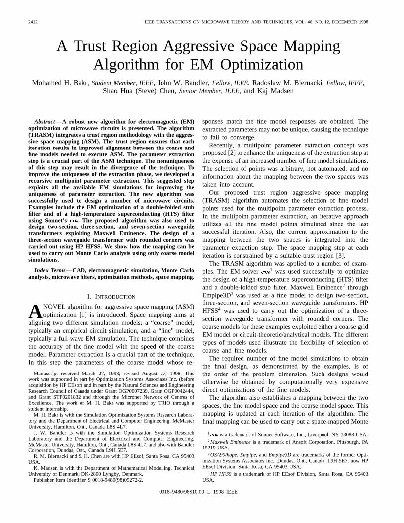
Fig. 1. Illustration of the automated multipoint parameter extraction. (a) The current state at theith iteration. (b) Initial parameter extraction at the suggestedpointXXXi+1
eeem . (c) Parameter extraction fails; an additional pointXXX1t is obtained and multipoint parameter extraction is carried out to sharpen the solution.
implementation, this success criterion is given by
(10)
The success criterion (10) ensures that the ratio between theactual reduction in the norm of the vector and thepredicted reduction is greater than a certain value. Otherwise,the validity of the extraction process leading to at thesuggested point is suspect. The residual vector isthen used to construct a candidate point from the pointby using (9). This candidate point is then added to the set ofpoints employed for simultaneous parameter extraction at thepoint . A new value for is obtained by solving
(11)
simultaneously for all , where is the set of finemodel points used for multipoint parameter extraction. Thismultipoint parameter extraction step differs from (8) in one
important aspect. A perturbation in the fine-model space ofcorresponds to a perturbation in the coarse-model space
of This is logical since the matrix representsthe most up-to-date approximation to the mapping between thetwo spaces. Thus, the available information about the mappingbetween the two spaces is exploited.
The new extracted coarse model parameters either satisfythe success criterion (10) or they are used to obtain anothercandidate point which is then added to the set, and thewhole process is repeated (see Fig. 1). This recursive mul-tipoint parameter extraction process is expected to improvethe uniqueness of the extraction step. This may lead to thesatisfaction of the success criterion (10) or the step is declareda failure. Failure is declared in one of two cases: either thevector of extracted parameters approaches a limiting valuewith the success criterion not satisfied, or the number offine model simulations since the last successful iteration hasreached In the first case, the extracted coarse modelparameters are trusted and the accuracy of the linearizationused to predict is suspected. Thus, to ensure a successfulstep from the current point , the trust region size is shrunkand a new suggested point is obtained. In the lattercase, sufficient information is available to obtain an estimate

BAKR et al.: TRUST REGION ASM ALGORITHM FOR EM OPTIMIZATION 2415
Fig. 2. The DFS filter [5].
for the Jacobian of the fine-model responses with respect tothe fine-model parameters. This is done by solving the systemof linear equations
......
(12)
where is the th candidate point used for multipointparameter extraction and is the corresponding error be-tween the fine-model response and the optimal coarse-modelresponse. This matrix is then used to obtain a stepin theparameter space by solving the system of equations
(13)
varying the parameter until If there is noreduction in the norm of the vector function , the trustregion is shrunk and (13) is resolved. This is repeated untileither the size of the trust region has shrunk significantly andhence the algorithm terminates or a successful step is taken.The successful step is then used instead of the step obtainedby (9).
At the end of each iteration, the ratio between the actualreduction in the norm of the vector and the predictedreduction using linearization is used to check the accuracy ofthe linearization. The criterion
(14)
was used to check how accurate the linearization is. If (14) issatisfied then we exploit the accuracy of the linearization andincrease the size of the trust region.
In the initialization phase we assign and, the identity matrix. Also, we assign values to the
two parameters and These two parameters are used todetermine the termination condition of the algorithm.
As there is no iteration prior to the first iteration, we arenot able to compare the norm of with a previous value toensure the uniqueness of the step. To ensure the uniqueness of
, the multipoint parameter extraction at the first point isrepeated for an increasing number of points in the setuntilit approaches a limiting value. This limiting value can then betrusted and the algorithm proceeds. For any iteration ,the basic steps taken are as follows.
TABLE IMATERIAL AND PHYSICAL PARAMETERS FOR THE
COARSE AND FINE ememem MODELS OF THE DFS FILTER
Fig. 3. The optimal coarse model response ( ) and the fine modelresponse(�) at the starting point for the DFS filter.
TABLE IIVALUES OF OPTIMIZABLE PARAMETERS AT EACH ITERATION FOR THEDFS FILTER
TRASM Algorithm
Step 0: Given and Set
Step 1: Obtain by solving (9) with Let
Step 2: If stop else evaluate using(5) and set
Step 3: Apply multipoint parameter extraction using thepoints in the set to obtain
Step 4: If the success criterion (10) is satisfied go toStep 9.
Step 5: If is equal to one go to Step 8.

2416 IEEE TRANSACTIONS ON MICROWAVE THEORY AND TECHNIQUES, VOL. 46, NO. 12, DECEMBER 1998
Fig. 4. The optimal coarse model response ( ) and the final fine modelresponse(�) for the DFS filter.
Fig. 5. The structure of the HTS filter [1], [7].
Comment: denotes the cardinality of the setStep 6: Compare obtained using fine-model
points with that previously obtained usingfine-model points. If is approaching a
limiting value, shrink the trust region sizeand go to Step 1.
Step 7: If is equal to , obtain an approximation forthe Jacobian of the fine-model responses, shrinkthe trust region size , evaluate a new step
by solving (13) with for asuitable value of that results in the reductionin the norm of the vector and go to Step 2.
Comment: The trust region is shrunk to ensure a successfulstep.
Step 8: Obtain a temporary point usingand Add this point to the set and goto Step 3.
Step 9: Update the matrix to using Broy-den’s formula [4].
Step 10: If stop.Step 11: Increase the trust region size if (14) is
satisfied.Step 12: Let Go to Step 0.
The algorithm terminates if the size of the trust regionhas shrunk below a certain threshold or if there is no significantchange in the fine model responses in two consecutive itera-tions. The algorithm produces two main results. These resultsare the final fine-model design and the matrix whichrepresents the mapping between the two spaces.
In our implementation, proper scaling is applied to theoptimizable parameters to make them of the same order. The
TABLE IIIMATERIAL AND PHYSICAL PARAMETERS FOR THEHTS FILTER
Fig. 6. The optimal coarse model response (—) and the fine model response(�) at the starting point for the HTS filter.
Fig. 7. The variation of two of the extracted coarse model parameters in thefirst iteration with the number of points used for parameter extraction where(1) is obtained using a single fine-model point, (2) is obtained using twofine-model points, and (3) is obtained using three fine-model points.
initial trust region size is taken as 2% to 10% of the normof the vector of scaled parameters.
V. EXAMPLES
Double-Folded Stub Filter
We consider the design of the double-folded stub (DFS)microstrip structure shown in Fig. 2 [5]. Folding the stubs

BAKR et al.: TRUST REGION ASM ALGORITHM FOR EM OPTIMIZATION 2417
(a) (b)
(c)
Fig. 8. The coarse model response (—) and the fine model response(�) corresponding to the three extracted points in Fig. 7 where (a) is obtained usinga single fine-model point, (b) is obtained using two fine-model points, and (c) is obtained using three fine-model points.
reduces the filter area w.r.t. the conventional double-stubstructure [6]. The filter is characterized by five parameters:
and (see Fig. 2). and arechosen as optimization variables. and are fixed at 4.8mil. The design specifications are given by dB inthe passband and dB in the stopband, where thepassband includes frequencies below 9.5 GHz and above 16.5GHz and the stopband lies in the range [12 GHz, 14 GHz].The structure is simulated by Sonnet’s through Empipe.The coarse model is a coarse-grid model with cell size 4.8mil by 4.8 mil. The fine model is a fine-grid model withcell size 1.6 mil by 1.6 mil. Other parameters are summarizedin Table I.
Fig. 3 shows the optimal coarse-model response alongwith the fine-model response evaluated using the optimalcoarse-model parameters. The time needed to simulate thestructure (coarse model) at a single frequency is only 5CPU seconds on a Sun SPARCstation 10. This includes theautomatic response interpolation carried out to accommodateoff-grid geometries.
It is clear from Fig. 3 that the fine-model response violatesthe design specifications at the starting point. The new ASMalgorithm required only two iterations to reach the finaldesign. The algorithm’s progress is shown in Table II. Thenumber of fine-model points needed is five. Linear responseinterpolation was enabled to simulate the off-grid fine-modelpoints. The response of the fine-model at the final design is
shown in Fig. 4. The CPU time needed for the fine model isapproximately 70 s per frequency point.
HTS Filter
We consider optimization of an HTS filter [1], [7]. Thisfilter is illustrated in Fig. 5. The specifications are
in the passband and in the stopband,where the stopband includes frequencies below 3.967 GHzand above 4.099 GHz, and the passband lies in the range[4.008 GHz, 4.058 GHz]. The design variables for this problemare and We take miland mil. The coarse model exploits the empiricalmodels of microstrip lines, coupled lines, and open stubsavailable in OSA90/hope. The fine model employs a fine-grid
simulation. The material and physical parameters valuesused in both OSA90/hope and in are shown in Table III.The coarse model is first optimized using the OSA90/hopeminimax optimizer. The fine-model response at the optimalcoarse-model design is shown in Fig. 6. The parameter ex-traction for this problem has several solutions. Fig. 7 showshow two of the extracted coarse-model parameters changedwith the number of points used for parameter extractionin the first iteration. The first point (1) is obtained usingnormal parameter extraction. These extracted values wouldhave caused the original ASM technique to diverge. The newtechnique automatically generates a candidate point whichis then used together with the original point to carry out a

2418 IEEE TRANSACTIONS ON MICROWAVE THEORY AND TECHNIQUES, VOL. 46, NO. 12, DECEMBER 1998
(a) (b)
(c) (d)
Fig. 9. The coarse-model response (—) at the extracted point and the fine-model response(�) corresponding to the second, third, fourth, and fifth iterations.
TABLE IVINITIAL AND FINAL DESIGNS OF THEFINE MODEL FOR THE HTS FILTER
two-point parameter extraction, and the second point (2) isobtained. To confirm that this point is the required one, a thirdcandidate point is automatically generated and the extractionis repeated using the three points to obtain the third extractedpoint (3). The second and third extracted points show that theextracted vector of coarse model parameters is approachinga limiting value and can thus be trusted. The coarse modelresponses corresponding to the three extracted points of Fig. 7are shown in Fig. 8.
For the remaining iterations, single-point parameter extrac-tion worked well. The fine-model responses and the coarse-model responses for the corresponding extracted points areshown in Fig. 9. The final fine-model design was obtained
Fig. 10. The optimal coarse-model response (—) and the final fine-modelresponse(�) for the HTS filter.
in five iterations which required eight fine-model simulations.The final fine-model design is given in Table IV. The fine-model response at this design is shown in Fig. 10. Thepassband ripples are shown in Fig. 11.
In the original space mapping approaches [1], [7], this ex-ample required significant manual intervention to successfullycomplete the parameter extraction phase. Furthermore, withoutsuch intervention the previous approaches would not work.

BAKR et al.: TRUST REGION ASM ALGORITHM FOR EM OPTIMIZATION 2419
TABLE VVALUES OF OPTIMIZABLE PARAMETERS AT EACH ITERATION OF THE NEW ASM TECHNIQUE
FOR THE TWO-SECTION WAVEGUIDE TRANSFORMER USING TWO ANALYTICAL MODELS
TABLE VIVALUES OF OPTIMIZABLE PARAMETERS AT EACH ITERATION OF THE NEW ASM TECHNIQUE FOR THE
TWO-SECTION WAVEGUIDE TRANSFORMER USING MAXWELL EMINENCE AND AN IDEAL ANALYTICAL MODEL
TABLE VIIVALUES OF OPTIMIZABLE PARAMETERS AT EACH ITERATION OF THE NEW ASM TECHNIQUE
FOR THE THREE-SECTION WAVEGUIDE TRANSFORMER USING TWO ANALYTICAL MODELS
Fig. 11. The optimal coarse-model response (—) and the final fine-modelresponse(�) for the HTS filter in the passband.
Fig. 12. A typical two-section waveguide transformer.
Waveguide Transformers
Three designs of two-, three-, and seven-section waveguidetransformers were considered. The two-section waveguidetransformer is shown in Fig. 12. These examples are classicalmicrowave circuit design problems [8]. Two different sets of

2420 IEEE TRANSACTIONS ON MICROWAVE THEORY AND TECHNIQUES, VOL. 46, NO. 12, DECEMBER 1998
Fig. 13. The optimal response of the ideal analytical model (—) and theresponse of the nonideal analytical model(�) at the starting point for thetwo-section waveguide transformer.
Fig. 14. The optimal response of the ideal analytical model (—) and the finalresponse of the nonideal analytical model(�) for the two-section waveguidetransformer.
Fig. 15. The optimal response of the ideal analytical model (—) and theresponse of Maxwell Eminence(�) at the starting point for the two-sectionwaveguide transformer.
models were used. The first set exploits two empirical models:an “ideal” analytical model which neglects the junction discon-tinuity and a more accurate “nonideal” analytical model whichincludes the junction discontinuity effects [8]. The second setuses the ideal analytical model of the first set as the coarsemodel while Maxwell Eminence is used as the fine model.
Fig. 16. The optimal response of the ideal analytical model (—) and the finalMaxwell Eminence response(�) for the two-section waveguide transformer.
Fig. 17. The optimal response of the ideal analytical model (—) and theresponse of the nonideal analytical model(�) at the starting point for thethree-section waveguide transformer.
The designable parameters for these design problems are theheight and length of each waveguide section.
The two-section transformer is optimized using the twoanalytical models. The optimum ideal model response is shownin Fig. 13 along with the nonideal model response at the samepoint. Our algorithm terminated in three iterations, requiringfive fine-model simulations. The final nonideal model design isgiven in Table V. The corresponding nonideal model responseis shown in Fig. 14. This example is known to have more thanone minimum for the parameter extraction step [2]. However,our new algorithm converged successfully. The number ofsimulations needed to align the two models is smaller thanthat reported in [2]. The same transformer is then optimizedusing Maxwell Eminence and the ideal analytical model.Nine adaptive passes were allowed for Maxwell Eminencewith allowable delta S set to 0.0001. The initial fine-modelresponse is shown in Fig. 15. The final design was obtainedin three iterations which required five Maxwell Eminence fine-model simulations. This is one half the number of fine-model

BAKR et al.: TRUST REGION ASM ALGORITHM FOR EM OPTIMIZATION 2421
Fig. 18. The optimal response of the ideal analytical model (—) and the finalresponse of the nonideal analytical model(�) for the three-section waveguidetransformer.
Fig. 19. The optimal response of the ideal analytical model (—) and theresponse of Maxwell Eminence(�) at the starting point for the three-sectionwaveguide transformer.
TABLE VIIIVALUES OF OPTIMIZABLE PARAMETERS AT EACH ITERATION OF THE NEW
ASM TECHNIQUE FOR THETHREE-SECTION WAVEGUIDE TRANSFORMER
USING MAXWELL EMINENCE AND AN IDEAL ANALYTICAL MODEL
simulations reported in [2]. The Maxwell Eminence fine-modeldesign is shown in Table VI and the corresponding fine-modelresponse is shown in Fig. 16.
The previous steps were repeated for the three-sectionwaveguide transformer. The initial fine-model response is
Fig. 20. The optimal response of the ideal analytical model (—) and the finalMaxwell Eminence response(�) for the three-section waveguide transformer.
Fig. 21. The optimal ideal analytical model response (—) and the responseof the nonideal analytical model(�) at the starting point for the seven-sectionwaveguide transformer.
Fig. 22. The optimal response of the ideal analytical model (—) and the finalresponse of the nonideal analytical model(�) for the seven-section waveguidetransformer.
shown in Fig. 17. Using the two analytical models, the finaldesign was obtained in four iterations which required six fine-model simulations. This final design is shown in Table VII.

2422 IEEE TRANSACTIONS ON MICROWAVE THEORY AND TECHNIQUES, VOL. 46, NO. 12, DECEMBER 1998
TABLE IXVALUES OF OPTIMIZABLE PARAMETERS AT THE INITIAL
AND FINAL DESIGN FOR THESEVEN-SECTION WAVEGUIDE
TRANSFORMER USING TWO ANALYTICAL MODELS
Fig. 23. The optimal response of the ideal analytical model (—) and theresponse of Maxwell Eminence(�) at the starting point for the seven-sectionwaveguide transformer.
The corresponding fine-model response is indistinguishablefrom the optimal coarse-model response as shown in Fig. 18.
The design of the three-section transformer is then repeatedusing Maxwell Eminence and the ideal analytical model. Weallowed only five adaptive passes with the same value ofallowable delta S as before. The initial Maxwell Eminencefine-model response is shown in Fig. 19. The algorithm termi-nated in two iterations with a total number of nine fine-modelsimulations. Most of these fine-model simulations were usedto shrink the trust region around the final design. The finaldesign is shown in Table VIII. The corresponding MaxwellEminence fine-model response is shown in Fig. 20.
The design of a seven-section waveguide transformer wasalso considered. The designable parameters for this problemare the height and length of each waveguide section. Using
Fig. 24. The optimal response of the ideal analytical model (—) and the finalMaxwell Eminence response(�) for the seven-section waveguide transformer.
TABLE XVALUES OF OPTIMIZABLE PARAMETERS AT THE INITIAL AND FINAL
DESIGN FOR THESEVEN-SECTION WAVEGUIDE TRANSFORMER
USING MAXWELL EMINENCE AND AN IDEAL ANALYTICAL MODEL
the two analytical models, the final design was obtained inthree iterations which required six fine-model simulations. Theinitial fine-model response is shown in Fig. 21. The fine-modelresponse corresponding to the final design is almost identicalto the optimal coarse-model response as shown in Fig. 22.Table IX shows the final fine model design.
Finally, the design of the seven-section transformer wascarried out using Maxwell Eminence and an ideal analyticalmodel. We allowed ten refinement passes with allowable deltaS of 0.001. The algorithm terminated in three iterations whichrequired 11 Maxwell Eminence fine-model simulations. Theinitial Maxwell Eminence response is shown in Fig. 23. Thefinal fine-model response is shown in Fig. 24. Table X showsthe corresponding Maxwell Eminence fine model design.

BAKR et al.: TRUST REGION ASM ALGORITHM FOR EM OPTIMIZATION 2423
Fig. 25. The simulated part of the three-section waveguide transformer withrounded corners [9].
A Three-Section Waveguide Transformerwith Rounded Corners [9]
In this example, we considered the design of a three-sectiontransformer with rounded corners. The designable parametersfor this problem are the height and length of each waveguidesection. The specifications are dB for a rangeof frequencies extending from 9.5 to 15 GHz. The fine modelof this circuit exploits HP HFSS. The coarse model exploitsan ideal empirical model that does not take into account therounding of the corners. One quadrant of the transformer isshown in Fig. 25. We exploited the geometrical symmetry ofthe problem to reduce the required CPU time of HP HFSS.
Each time a new HP HFSS simulation is requested bythe algorithm, a new project is created using the new valuesfor the length and height of each section. To facilitate thisprocess, a MATLAB5 program was developed that convertsthe values of the designable parameters into the correspondingHP HFSS drawing commands with the appropriate values. Thisapproach accelerates the generation of new HP HFSS projectsand eliminates the possibility of wrong dimensions.
The initial response of the fine model at the optimal coarse-model design is shown in Fig. 26. Clearly, the specificationsare slightly violated at this point. Only one iteration wasneeded to reach the final fine-model design. The requirednumber of HP HFSS simulations is seven. The first three ofthese simulations were needed to trust the parameter extractionat the first point. The other fine-model points were needed tocontract the size of the trust region to the termination size.The final HP HFSS fine-model design is given in Table XI.The corresponding fine-model response is shown in Fig. 27.
VI. M ONTE CARLO ANALYSIS USING SPACE MAPPING [5]
The final matrix obtained by the algorithm representsthe best available information about the mapping between thetwo spaces. A perturbation of in the fine-model space ismapped to a perturbation of in the coarse-model space by
(15)
The perturbations in the coarse-model space and fine-modelspace are with respect to and , respectively. The
5MATLAB Version 5.0 is a registered trademark of The Math. Works, Inc.,Natick, MA 01760 USA.
Fig. 26. The optimal response of the ideal analytical model (—) and theresponse of HP HFSS(�) at the starting point for the three-section waveguidetransformer with rounded corners.
TABLE XIVALUES OF OPTIMIZABLE PARAMETERS AT EACH ITERATION OF THE NEW ASM
TECHNIQUE FOR THETHREE-SECTION WAVEGUIDE TRANSFORMER WITH
ROUND CORNERSUSING HP HFSSAND AN IDEAL ANALYTICAL MODEL
Fig. 27. The optimal response of the ideal analytical model (—) and thefinal HP HFSS response(�) for the three-section waveguide transformer withrounded corners.
established mapping can be used to perform a space-mappedMonte Carlo analysis [5] for the problem under consideration.The random points generated in the fine-model space aremapped to the coarse-model space using (15). Coarse-modelsimulations are then used instead of the CPU-intensive fine-model simulations. This statistical analysis should enjoy thespeed of the coarse model and the accuracy of the fine model.

2424 IEEE TRANSACTIONS ON MICROWAVE THEORY AND TECHNIQUES, VOL. 46, NO. 12, DECEMBER 1998
Fig. 28. Monte Carlo analysis for the three-section waveguide transformerwith rounded corners assuming 1% uniformly distributed parameters.
Fig. 29. Monte Carlo analysis for the three-section waveguide transformerwith rounded corners assuming 2% uniformly distributed parameters.
Fig. 30. Monte Carlo analysis for the three-section waveguide transformerwith rounded corners assuming 5% uniformly distributed parameters.
To demonstrate this approach, we carried out a MonteCarlo analysis of the three-section waveguide transformer withrounded corners. The fine-model parameters were assumedto be uniformly distributed with tolerances of 1, 2, and 5%.The corresponding responses are shown in Figs. 28–30. Theestimated yields for these tolerances are 39, 4, and 0%.
VII. CONCLUSIONS
A powerful new algorithm implementing the aggressivespace mapping technique is introduced. The new algorithm,
TRASM, automatically improves the uniqueness of the pa-rameter extraction step, the most critical step in the spacemapping process, and exploits all available fine-model simula-tions. Also, the proposed algorithm integrates the trust regionconcept with the original ASM technique. Through exampleswhich have proved difficult in the past, we show that theTRASM algorithm automatically overcomes the nonunique-ness of the parameter extraction step in a logical way. Theresults show that very few EM simulations are needed toreach the final design. We showed also how the establishedmapping between the two spaces can be used to carry out aspace-mapped Monte Carlo analysis of the fine model.
ACKNOWLEDGMENT
The authors thank Sonnet Software, Inc., Liverpool, NY,for making available for this work. They thank AnsoftCorporation, Pittsburgh, PA, for making Maxwell Eminenceavailable, and HP EEsof, Santa Rosa, CA, for making HPHFSS available.
REFERENCES
[1] J. W. Bandler, R. M. Biernacki, S. H. Chen, R. H. Hemmers,and K. Madsen, “Electromagnetic optimization exploiting aggressivespace mapping,”IEEE Trans. Microwave Theory Tech., vol. 43, pp.2874–2882, 1995.
[2] J. W. Bandler, R. M. Biernacki, and S. H. Chen, “Fully automated spacemapping optimization of 3D structures,” inIEEE MTT-S Int. MicrowaveSymp. Dig., San Francisco, CA, 1996, pp. 753–756.
[3] J. J. More and D. C. Sorenson, “Computing a trust region step,”SIAMJ. Sci. Stat. Comp., vol. 4, pp. 553–572, 1983.
[4] C. G. Broyden, “A class of methods for solving nonlinear simultaneousequations,”Math. Comp., vol. 19, pp. 577–593, 1965.
[5] J. W. Bandler, R. M. Biernacki, S. H. Chen, P. A. Grobelny, and R. H.Hemmers, “Space mapping technique for electromagnetic optimiztion,”IEEE Trans. Microwave Theory Tech., vol. 42, pp. 2536–2544, 1994.
[6] J. C. Rautio, private communication, 1992.[7] J. W. Bandler, R. M. Biernacki, S. H. Chen, W. J. Gestinger, P. A.
Grobelny, C. Moskowitz, and S. H. Talisa, “Electromagnetic designof high-temperature superconducting filters,”Int. J. Microwave andMillimeter-Wave CAE, vol. 5, pp. 331–343, 1995.
[8] J. W. Bandler, “Computer optimization of inhomogeneous waveguidetransformers,”IEEE Trans. Microwave Theory Tech., vol. MTT-17, pp.563–571, 1969.
[9] Empipe3DTM Manual, Version 4.0, formerly Optimization SystemsAssociates Inc., Dundas, Ont., Canada, L9H 5E7, 1997, Chapter 5, nowHP EEsof Division, Santa Rosa, CA 95403.
Mohamed H. Bakr (S’98) was born in Cairo,Egypt, on November 7, 1969. He received theB.Sc. degree in electronics and communicationsengineering from Cairo University, Egypt, in 1992with distinction (honors). In 1996 he received theMasters degree in engineering mathematics fromCairo University.
In October 1992, he joined the Department ofEngineering Mathematics and Physics, Faculty ofEngineering, Cairo University. He joined the De-partment of Electrical and Computer Engineering,
McMaster University, Hamilton, Ont., Canada in September 1996, where heis currently a Ph.D. student. His research is carried out in the SimulationOptimization Systems Research Laboratory. During the 1997/1998 academicyear, he held a student internship from the Telecommunications ResearchInstitute of Ontario to work at Optimization Systems Associates, Inc. Heis interested in optimization methods, computer-aided design of microwavecircuits, and neural networks.
Mr. Bakr currently holds an Ontario Graduate Scholarship.

BAKR et al.: TRUST REGION ASM ALGORITHM FOR EM OPTIMIZATION 2425
John W. Bandler (S’66–M’66–SM’74–F’78) wasborn in Jerusalem, on November 9, 1941. He studiedat Imperial College of Science and Technology,London, England, from 1960 to 1966. He receivedthe B.Sc.(Eng.), Ph.D., and D.Sc.(Eng.) degreesfrom the University of London, London, England,in 1963, 1967 and 1976, respectively.
He joined Mullard Research Laboratories, Red-hill, Surrey, England in 1966. From 1967 to 1969 hewas a Postdoctorate Fellow and Sessional Lecturerat the University of Manitoba, Winnipeg, Canada.
He joined McMaster University, Hamilton, Canada, in 1969, where he iscurrently Professor of Electrical and Computer Engineering. He has served asChairman of the Department of Electrical Engineering and Dean of the Facultyof Engineering. He currently directs research in the Simulation OptimizationSystems Research Laboratory. He is a member of the Micronet Network ofCentres of Excellence. He was President of Optimization Systems AssociatesInc. (OSA), which he founded in 1983, until November 20, 1997, the dateof acquisition of OSA by Hewlett-Packard Company (HP). He is Presidentof Bandler Corporation, which he founded in 1997. He was an AssociateEditor of the IEEE TRANSACTIONS ON MICROWAVE THEORY AND TECHNIQUES
(1969–1974) and has continued serving as a member of the Editorial Board. Hejoined the Editorial Boards of theInternational Journal of Numerical Modelingin 1987, and theInternational Journal of Microwave and MillimeterwaveComputer-Aided Engineeringin 1989. He has published more than 300 papersfrom 1965 to 1998.
Dr. Bandler is a fellow of the Royal Society of Canada, a fellow ofthe Institution of Electrical Engineers (Great Britain), a member of theAssociation of Professional Engineers of the Province of Ontario (Canada)and a member of the MIT Electromagnetics Academy. He serves as co-chair of the IEEE MTT-S Technical Committee on Computer-Aided Design.He received the Automatic Radio Frequency Techniques Group (ARFTG)Automated Measurements Career Award in 1994.
Radoslaw M. Biernacki (M’85–SM’86–F’96) wasborn in Warsaw, Poland. He received the Ph.D.degree from Warsaw University of Technology in1976.
He became a Research and Teaching Assistantin 1969 and an Assistant Professor in 1976 atthe Institute of Electronics Fundamentals, WarsawUniversity of Technology, Warsaw, Poland. From1978 to 1980 he was on leave with the ResearchGroup on Simulation, Optimization and Control andwith the Department of Electrical and Computer En-
gineering, McMaster University, Hamilton, Canada, as a Postdoctorate Fellow.From 1984 to 1986 he was a Visiting Associate Professor at Texas A&MUniversity, College Station. From 1986 to 1997 he was with OptimizationSystems Associates Inc., Dundas, Ont., Canada, where he was involved inthe development of OSA’s commercial CAE software systems and relatedresearch. During this period his academic research was carried out in theSimulation Optimization Systems Research Laboratory, McMaster University.In 1997, after acquisition of OSA, he joined the R&D team of HP EEsof. Hisresearch in the area of computer-aided engineering has included parameterextraction, statistical device modeling, simulation and optimization, yield-driven design of linear and nonlinear microwave circuits, and electromagneticdesign optimization. He has more than 100 publications. He is also anAdjunct Professor in the Department of Electrical and Computer Engineering,McMaster University, Hamilton, Canada.
Shao Hua (Steve) Chen(S’84–M’88–SM’95) wasborn in Swatow, China. He received the B.S. (Eng.)degree in 1982 from the South China Institute ofTechnology in Guangzhou, China, and the Ph.D.degree in electrical engineering in 1987 from Mc-Master University in Hamilton, Ont., Canada.
From July 1982 to August 1983 he was a Teach-ing Assistant in the Department of Automation atthe South China Institute of Technology. Duringhis graduate study at McMaster University from1983 to 1987, he was awarded an Ontario Graduate
Scholarship for two years. He joined Optimization Systems Associates Inc.,Dundas, Ont., Canada, in 1987 and has made major contributions to thecommercial CAD software development. He has also worked as a SeniorResearch Engineer in the Simulation Optimization Systems Research Labo-ratory at McMaster University and engaged in pioneering research on CADsimulation and modeling technology and optimization techniques. In 1997 hejoined the Technical Staff at Hewlett-Packard Company, HP EEsof Division.His professional interests include optimization theory and implementation,CAD software architecture, electromagnetic optimization, electronic devicemodeling, statistical circuit simulation, and computer graphics. He has over60 technical publications.
Kaj Madsen was born in Denmark in 1943. Hereceived the cand.scient. degree in mathematicsfrom the University of Aarhus in 1968 and thedr.techn. degree from the Technical University ofDenmark in 1986.
From 1968 to 1988 he was a Lecturer in Nu-merical Analysis, apart from the academic year1973 to 1974, when he was with AERE Harwell,Didcot, England. Most of his career has been spentwith the Institute for Numerical Analysis, Techni-cal University of Denmark, but during the years
1981 to 1983 he was with the Computer Science Department, CopenhagenUniversity. During the summer of 1978, he visited McMaster University,Hamilton, Ont., Canada. In 1988 he became Professor with the Institute forNumerical Analysis, Technical University of Denmark. In 1993 he joined theDepartment of Mathematical Modelling, Technical University of Denmark.During 1988–1993 and since 1995 he has been Head of Department. His fieldsof interest in teaching and research are parallel algorithms, optimization, andinterval analysis.