a ventilation system capstone design project
TRANSCRIPT
AC 2008-1308: A VENTILATION SYSTEM CAPSTONE DESIGN PROJECT
Charles Forsberg, Hofstra UniversityCharles H. Forsberg is an Associate Professor of Engineering at Hofstra University, where heprimarily teaches courses in the thermal/fluids area. He received a B. S. in MechanicalEngineering from the Polytechnic Institute of Brooklyn (now Polytechnic University), and an M.S. in Mechanical Engineering and Ph. D. from Columbia University. He is a LicensesdProfessional Engineer in New York State.
© American Society for Engineering Education, 2008
Page 13.129.1

A Ventilation System Capstone Design Project
I. Introduction The Hofstra University mechanical engineering program requires students to take two capstone design courses – one in the mechanics area; the other in the thermal/fluids area. This paper discusses a Spring 2007 design project in the latter area; in particular, a project dealing with design of a ventilation system for a room. Over the past four years, our department has experienced an increase in enrollment in the mechanical engineering program. We are not completely sure as to the reason for this. Perhaps the increase is due to the students’ perception of an improved job market in the ME discipline. It may also be due to the mechanical faculty’s emphasis on teaching and interaction with students rather than research. It may be due to improved lab facilities. And, it could be due to the students’ observation of high quality senior design projects of a practical nature. Regardless of the cause, the increased enrollment has been reflected in an increase in the size of our classes. In the past, the senior design thermal/fluids course typically had an enrollment of between five and ten. However, in Spring 2007 the enrollment reached eighteen, an all-time high. Also, the department had recently passed a rule that no more than three students could be in a design group. Hence, projects were needed for six groups, rather than the usual two. Finding suitable projects is never an easy task (at least for this professor). Fortunately, equipment funds were available from an ASHRAE Senior Undergraduate Project Grant, and it was decided to have two of the six groups work independently on design and construction of a ventilation system for the thermal/fluids lab. The system was to be temporary. After conclusion of the semester it was to be removed and stored for potential future use in the laboratories. As discussed below, the project was very successful. Students received a valuable design and construction experience, and the project has resulted in a new experiment for the mechanical engineering laboratories. II. System Specifications Students were given the following design specifications for the ventilation system: The ventilation system should have five (5) diffusers, each providing 100 cfm of air to the room. The instructor provided the locations of the diffusers and also the location of the fan. Figure No. 1 shows the required location of the fan and the required locations of the five diffusers. The possible duct routings are shown as dashed lines. The students had to size and route the ductwork from the fan to the diffusers. At first, it was planned to temporarily support the ducts from the ceiling. This proved to be unfeasible due to
Page 13.129.2

lack of suitable ceiling supports. Therefore, it was decided to support the ducts on chairs in the aisles and other open areas of the room. Some experiments in the room are on movable carts, and these were allowed to be moved. Other experiments, however, are larger and difficult to move (e. g., wind tunnels and the hydraulic channel). The students had to route the ductwork around these obstacles. The dashed lines on the below sketch show possible routings. There are at least five possible routings from the fan to the diffusers, and the students had to select the routing that resulted in the lowest equipment cost.
Figure No. 1 - Room Layout showing location of fan and diffusers and
possible duct routings
F
Hallway
Outside
5 4
3
2 1
Page 13.129.3

The ducts were sized using the Trane Company VariTrane Duct Design software 1. The
ducts had to be of sufficient quality to allow disassembly, reassembly and storage without damage. The fan or blower was to be of good quality, but reasonable cost. It was suggested by the instructor that perhaps an in-duct fan or centrifugal fan/blower would suffice. The students had to provide the instructor with a bill of materials, including prices, for the desired ducts, fittings, dampers, and fan. After the parts were ordered and received, the students had to assemble the system and test it. They had to experimentally determine the air flows at the five diffusers and balance the system for equal flows of 100 cfm through each diffuser. They also had to experimentally determine the pressure at the fan outlet. III. The Design A. Ducts Heavy gauge clamp-together ducts were used. The ducts are galvanized steel of 22 and 24 gauge. Elbows are one gauge heavier than straight lengths. Branches and reducers are even heavier (18 gauge). The duct sections and fittings have rolled lips on their ends, and a stainless steel clamp with Buna N O-ring gasket connects the parts together. This results in a rugged, high quality duct system that is easy to assemble and disassemble.
The ducts were purchased from Kirk and Blum2. The ducts can also be obtained from
MSC Direct3. K & B, however, has a more extensive online catalog.
Both groups decided that the routing shown in Figure No. 2 resulted in the lowest duct costs.
Page 13.129.4
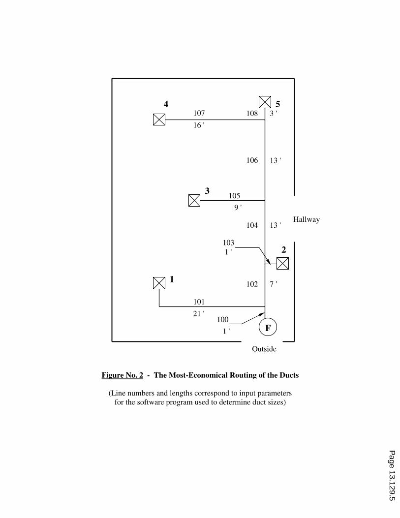
Figure No. 2 - The Most-Economical Routing of the Ducts
(Line numbers and lengths correspond to input parameters
for the software program used to determine duct sizes)
F
Hallway
Outside
5 4
3
2
1
107
16 '
105
9 '
108 3 '
106 13 '
104 13 '
102 7 '
101
21 '
103
1 '
100
1 '
Page 13.129.5

Figures 3, 4, and 5 show the completed duct system in the laboratory.
Figure No. 3 - The beginning of the system.
Figure No. 4 - Continuation of the system.
Fan
Diffuser
No. 2
Branch to
Diffuser No. 1
Diffuser
No. 5
Diffuser
No. 2 Branch to
Diffuser
No. 4
Branch to
Diffuser
No. 3
Page 13.129.6

Figure No. 5 - A view of the system, looking back towards
the fan.
Following is the Bill of Materials for the ductwork: Quantity Description 10 4” Galvanized Duct, Rolled Lip (5 ft. long) 3 6” Galvanized Duct, Rolled Lip (5 ft. long) 4 8” Galvanized Duct, Rolled Lip (5 ft. long) 5 4” Adjustable Sleeves, Galvanized, w/o-ring 1 6” Adjustable Sleeves, Galvanized, w/o-ring 3 8” Adjustable Sleeves, Galvanized, w/o-ring 5 4” 90 deg. elbows, Galvanized 21 Clamp & Pin, SS, 4” 5 Clamp & Pin, SS, 6” 10 Clamp & Pin, SS, 8” 1 Branch Tee, Galvanized, 6” @ 90 degree, 6-4-4 1 Branch Tee, Galvanized, 8” @ 90 degree, 8-6-4 2 Branch Tee, Galvanized, 8” @ 90 degree, 8-8-4 1 Reducer, Galvanized, 10 x 8 5 4” Butterfly Valves, Galvanized Total cost of the ductwork, including shipping from North Carolina to New York, was $ 1,830.
Fan
Diffuser
No. 3
Page 13.129.7

Ducts were sized using the Trane VariTrane Duct Designer software4. The software is
reasonably priced, comes with an excellent manual, and is relatively easy to learn. It is menu-driven. The user can select duct sizing by either the equal friction or the static regain method. (Equal friction was used for this project.) The user inputs the block fan
air flow (cfm) and the fan outlet diameter (determined by ASHRAE guidelines5). The
desired airflow from each diffuser is also specified. The user assigns a line number to each duct section and inputs the length of each section. (See Figure No. 2 above). The user also inputs the quantity and details of any inline fittings in the section (e. g., elbows). A variety of possible fittings can be selected from the menu. The user has to provide information regarding the origin of each duct section. For example, for line 105 in Figure No. 2: Line 105 comes from the upstream section 104 and is a branch from the tee. Line 106 also comes from upstream section 104, but it is the output of the tee, not the branch. The software automatically adds dampers to sections as needed for air balance. The software output gave the following duct sizes: Lines 102 and 104 - 8 inches Line 106 - 6 inches Lines 101, 103, 105, 107 and 108 - 4 inches Calculations using the equal friction method were also made by hand to check the
software results6. These calculations were tedious and took considerably longer than
using the software program. The results of the hand calculations were consistent with the software results. In addition to sizing the ductwork, the VariTrane Duct Designer software outputs a Bill of Materials for the duct sections and fittings. The weights of the duct sections are also output for cost estimating purposes. B. Fan The chosen fan was Fantech Model FX 10XL. This fan has a static pressure of 0.5 in. wg at 500 cfm and 3000 RPM. The fan has an outlet diameter of 10 inches. The duct design resulted in a desired outlet diameter of 8 inches. Hence, a 10 x 8 reducer was used to connect the fan to the duct system. The local branch of a large nationwide distributor had the fan for $ 393. However, we were able to purchase the fan from an online company,
HVAC Quick7, for $ 296, including shipping from California.
IV. Construction Due to the clamping nature of the ductwork, assembly of the system by the students was straightforward and quick. The only tool needed was a reciprocating saw to shorten some of the duct sections to meet the required lengths. (The students initially used a hacksaw. This was fine for the 4-inch diameter sections. But a reciprocating saw proved much more useful for the 6 and 8-inch diameter sections.)
Page 13.129.8

V. Experimental Results The objective of the project was to construct a ventilation system that provides an airflow of 100 cfm airflow from each of the five diffusers. To permit such balancing, butterfly dampers were installed at diffusers no. 1, 2, 3 and 5. No damper was needed at diffuser no. 4. Instrumentation included the following: Fan Speed Cole Parmer Model 8204-20 Tachometer (used optically) Air Velocity CFM Master 8901 Vane Digital Anemometer (obtained from Omega Engineering) Note: A hot-wire anemometer was initially used. Its readings fluctuated significantly and it was found that the averaging nature of a vane anemometer was superior for measuring the airflow from the diffusers. Air Pressure Dwyer Instruments Magnehelic Gage Model 2001 (0 to 1.0 in. wg) A. System Balancing Fan speed was adjusted to the fan manufacturer’s 3000 RPM rating. With all dampers fully open, the air velocities (fpm) from the diffusers varied significantly. They were: 1700, 1460, 1350, 920, and 1500 for diffusers 1 thru 5, respectively. By adjusting the dampers, we were able to get essentially equal air velocities out of all five diffusers: 1360, 1350, 1340, 1360, and 1330 fpm. The diffuser sections were all 4-inch duct, and the velocity values correspond to air flows of 119, 118, 117, 119, and 116 cfm, respectively. In short, balancing was achieved and essentially equal airflows (2% variation) were obtained from the five diffusers. However, the airflows at 3000 RPM were about 17 % greater than the desired 100 cfm. Without changing the damper settings, the fan speed was lowered from 3000 RPM to 2500, 2000, and 1500 RPM. Figure No. 6 shows the variation of total airflow from the five diffusers with fan speed. It is seen that the air flow varies linearly with fan speed. It is also seen that, by operating the fan at about 2500 RPM, rather than the rated 3000 RPM, the total air flow from the five diffusers will be the desired 500 cfm.
Page 13.129.9

In short, we were able to achieve the desired 100 cfm out of each diffuser by properly adjusting the dampers and operating the fan at 2500 RPM. At this speed, the measured air flows from the different diffusers varied from 97 to 103 cfm, a maximum variation of 3 % from the desired 100 cfm. B. Static Pressure at the Fan Outlet For the balanced system, with 100 cfm air flow from all diffusers, the VariTrane Duct Designer program predicted a static pressure at the fan outlet of 0.43 in. wg. We measured a static pressure at the fan outlet of 0.35 in. wg. The fan manufacturer’s performance curve for the fan is given in Figure No. 7 below. At 500 cfm flow, the manufacturer’s data shows a fan outlet pressure of about 0.5 in. wg.
Page 13.129.10

VI. Deliverables In addition to designing, constructing, and operating the ventilation system, the students were required to submit a professional-quality report documenting all aspects of their work. The students were also required to give an oral presentation to engineering faculty and students on Senior Design Presentation Day at the end of the semester. VII. Outcomes Assessment The two ABET outcomes relevant to this project are outcomes (c) and (g): ABET (c): An ability to design a system, component, or process to meet desired needs within realistic constraints such as economic, environmental, social, political, ethical, health and safety, manufacturability, and sustainability. ABET (g): An ability to communicate effectively. The two student groups were evaluated by faculty at the oral presentation using the department’s Senior Design Presentation Evaluation Sheet. The students’ design reports were evaluated by the instructor. The results were as follows: ABET (c) Design Aspects of the Project (5 = excellent, 3 = average, 1 = poor) Evaluated by faculty at Oral Presentations Group 1 Group 2 Design Introduction 4.10 4.70 Research/Investigation Outcomes 4.13 4.00 Alternative Designs Generated 4.67 4.20 Choice of and Justification 3.40 3.20 for Optimal Design Constructed or Analytical Model 3.40 3.20 Test and Evaluation of the 4.20 2.70 Design Solution Conclusions and Recommendations 4.67 3.88 Average: 4.08 3.70 ABET (g) Effective Communication Skills (5 = excellent, 3 = average, 1 = poor) Oral Communication Skills Evaluated by faculty at Oral Presentations
Page 13.129.11

Group 1 Group 2 Response to Questions 4.30 4.00 Communicating Your Design 4.50 5.00 Written Communication Skills Evaluation of Design Report by 5 3 the instructor It is seen that Group 1 performed better than Group 2. Group 1’s work was very good to excellent. Group 2’s work was good. VIII. Additional and Future Uses of the System The ventilation system was disassembled and placed into storage following the Spring 2007 semester. The clamping design of the ductwork resulted in fast and easy disassembly. The fan and a portion of the ductwork were used in Fall 2007 in the sophomore level Measurements and Instrumentation Laboratory to demonstrate the use of flow meters, tachometers and pressure gauges. This experimental apparatus is shown in Figure No. 8. The equipment will also be used in the senior mechanical engineering laboratory, where the students will determine the performance characteristics of the fan and investigate the laws relating fan capacity, speed, pressure and power. Figure No. 8 - Portion of System Used in Measurements and ME Labs
Page 13.129.12

IX. Conclusions This project was very beneficial to the students. It gave the students experience in both design and construction. It introduced students to software used in the HVAC industry and gave students practice in using test equipment. Finally, it gave the students an opportunity to improve their skills in both written and oral communications. The project has also been beneficial to the university. As mentioned above, the ventilation system is being incorporated into the laboratories and will be used in the education of students for years to come. X. Acknowledgments Many thanks to ASHRAE for providing funds for this project through an ASHRAE Senior Undergraduate Project Grant. References 1. Part of Trane’s University Package Two, which includes Trace 700 Load Design, VariTrane Duct Designer, and Trane Pipe Designer. Price is $ 295 plus $ 25 per seat. Annual licensing fee is 25% of the current University Package price. Website: www.trane.com/commercial. 2. Kirk and Blum, www.kbduct.com, Greensboro, NC. 3. MSC Direct, www.mscdirect.com, Industrial Clamp Together Ducting System, Page 4283 of 2007/2008 catalog, “The Big Book”. 4, See item #1 5. R. H. Howell, H. J. Sauer, Jr., W. J. Coad, Principles of Heating, Ventilating and Air Conditioning,
ASHRAE, 2005, Page 258. 6. R. H. Howell, H. J. Sauer, Jr., W. J. Coad, Principles of Heating, Ventilating and Air Conditioning,
ASHRAE, 2005, Chapter 9. 7. HVACQuick.com, San Jose, CA.
Page 13.129.13