a. w. - issct mcnee mill gearing.pdf · a. w. p. mcnee the mirrlees watson ... coupled to a single...
TRANSCRIPT

MILL GEARING
A. W. P. MCNEE
T h e Mirrlees Watson. Co. Ltd., Glasgow, Scotland
(Presented by the author)
MILL-GEARING DESIGN AND LAYOUT
Notable changes have taken place in mill-gearing design and layout in recent years. The main factors influencing these changes have been :
(I) The introduction'of the steam turbine as the prime mover in cane-mill drives with resultant higher input speeds.

u Fig. I.
Gear manufacturers pr~vide a wide choice of arrangements to achieve the necessary reductions. Some typical arrangements are illustrated in Figs. I to 6.
Fig. I shows a single mill driven by a 4,000 r.p.m. 600-h.p. turbine, through a totally enclosed single reduction double helical gearbox having a gear ratio of 6.3511 coupled to a single double helical pinion-and-wheel assembly of 17.611 gear ratio and
A. W. P. MCNEE 1127
finally a similar assembly with a gear ratio of 7.811. I t will be noted that the reduction is achieved in three stages.
Fig. 2 illustrates an arrangement incorporating a totally enclosed single reduction helical gearbox followed by a single double helical pinion-and-wheel assembly and finally a pinion-and-wheel of the machine-cut straight spur type.
Fig. 3 illustrates a similar arrangement to Fig. 2 but the turbine gearbox is of the double reduction double helical type and the main gears are all of the straight spur machine-cut type. Four reductions are used to give the overall gear reduction required.
In the three cases illustrated so far, each mill is individually driven and the gear bed is of the three-girder cast type.
Fig. 4 illustrates an arrangement in Which a single turbine is used to drive two mills through a double reduction turbine gearbox, a single double helical pinion-and- wheel arrangement and finally a machine-cut straight spur pinion-and-wheel assem- bly. Here the gear bed is of the two-girder type with the 1st motion pinion on top of the wheel giving a close compact arrangement very suitable for a small-sized milling plant.
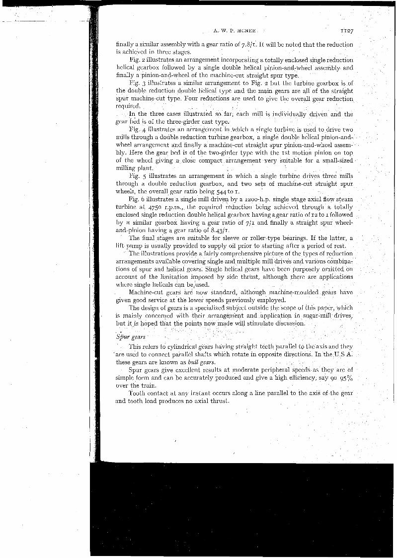
Fig. 5 illustrates an arrangement in which a single turbine drives three mills through a double reduction gearbox, and two sets of machine-cut straight spur wheels, the overall gear ratio being 544 to I.
Fig. G illustrates a single mill driven by a 1200-h.p. single stage axial flow steam turbine at 4750 r.p.m., the required reduction being achieved through a totally enclosed single reduction double helical gearbox having agear ratio of 12 to I followed by a similar gearbox having a gear ratio of 711 and finally a straight spur wheel- and-pinion having a gear ratio of 8.4311.
The final stages are suitable for sleeve or roller-type bearings. If the latter, a lift pump is usually provided to supply oil prior to starting after a period of rest.
The illustrations provide a fairly comprehensive picture of the types of reduction arrangements available covering single and multiple mill drives and various combipa- tions of spur and helical gears. Single helical gears have been purposely omitted on account of the limitation imposed by side thrust, although there are applications where single helicals can be,used.
Machine-cut gears are now standard, although machine-moulded gears have given good service at the lower speeds previously employed.
The design of gears is a specialized subject outside the scope of this paper, which is mainly concerned with their arrangement and application in sugar-mill drives, but it is hoped that the points now made will stimulate discussion.
S$uv geavs
This refers to cylindrical gears having straight teeth parallel to the axis and they 'are used to connect parallel shafts which rotate in opposite directions. In the U.S A. these gears are known as bull geavs.
Spur gears give excellent results at moderate peripheral speeds as they are of simple form and can be accurately produced and give a high efficiency, say 90-95% over the train.
Tooth contact at any instant occurs along a line parallel to the axik of the gear and tooth load produces no axial thrust.

Fig. 5 .
Fig. 6.

I
1130 FACTORY (ENGINEERING)
As the gears rotate, the line of contact moves up or down the profile, disapperir ilig abruptly so that the load on any tooth is suddenly applied and removed over the whole width simultaneously. At high speeds this would cause noise and vibration, and this led to the development of lielical gears.
for spur gears. Single helical gears are not often used in sugar-mill drives as the tooth load
has an axial component which necessitates the provision of a thrust bearing.
I
Simgle helical gears
Since the line of contact is inclined and not parallel to the axis as for a spur gear, giving different stages of tooth engagement: the tooth engagemellt and load distribution is gradual and they can therefore be used whereathe speed is too high
Double helical gears
A double helical gear is the equivalent of two single helical gears placed side by side with the teeth disposed as helices of equal angle but of opposite hand in order to balance the side thrust of the teeth. They have the gradual tooth engagement necessary for high-speed operation and since there are no limitations imposed by side thrust, they can carry heavier loads than single helical gears.
Double helical gears are superior to straight spur, owing to the higher load- carrying capacity, smoother running, as contact is distributed over a number oi teeth and less wear due to better rolling action. Efficiencies of 98% can be reached.
Wear on straight spur gears can be minimized by induction hardening, and.at the slow speeds prevailing in the latter stages of sugar-mill drives, straight-spur gears often provide a satisfactory answer.
Manufactre
Spur and do~ible helical gears may be form-milled, usually with an end miller, or generated by a planer or hobbing machine.
High-speed double helical gears are usually hobbed as this method gives the greatest accuracy, but a central gap is necessary to provide clearance for the hob when cutting the teeth. Gears cut by the planing process on the other hand, give the full-face width for load carrying, but are often left with a small gap to ensure teeth are not left proud at the apex, which could cause premature contact.
'
Materials
The required materials have to be carefully selected in accordance with size and duty. Pinions are generally high-carbon or alloy steel forgings, and at high speeds, are often made solid with the shafts. Wheels may be of cast steel, forged carbon steel or forged alloy steel. They may be fabricated, cast or consist of weldless steel rims on fabricated or cast centres.
Induction hardening of the gear teeth is now commonly practised, and since the surface hardness obtained is primarily dependent on the carbon content of the steel, plain carbon steels can often be used, as the alloying elements do not have much effect on this factor. This practice can provide a more suitable and cheaper gear

A. W. P. MCNEE 1131
GENERAL NOTES ON DESIGN
Spur gears
S to I is regarded as a suitable maximum reduction ratio. The pitch should be kept as fine as possible consistent with adequate strength. For ordinary gears, the face width should be about 4 times the pitch and not
over 5 or 6 times unless the gears are profile ground and shaved. For purposes of rigidity, pinion face widths should not exceed twice the diameter.
Similarly, wheel face widths should not be less than one tenth of the pitch diameter. For a zoo pressure angle, the number of teeth should be not less than 17 as
otherwise the gears would have to be corrected to avoid undercutting.
Double helical geavs
10 to I is regarded as a suitable single step reduction. The pitch should be kept as fine as possible, consistent with adequate strength. For 30° helix angle, the effective face width should be not less than 4 times
the normal pitch. To ensure rigid construction the pitch diameter of the wheel should not exceed
about 10 times the overall face width. The wheel should be located axially on the shaft and the pinion left free of axial
restraint other than that imposed by the teeth of the wheel. The number of teeth in the pinion should be not less than 20.
LUBRICATION
The importance of correct lubricant selection and application cannot be over- emphasized.
The relative action between gear teeth is a combination of rolling and sliding motion. Contact area is small and high specific pressures are encountered, thus lubrication with high-grade oil is necessary to avoid metal-to-metal contact.
Full use should be made of the services generally provided by lubricant suppliers of making their service engineer available during the annual gear inspection.
There are many recorded cases of gear failure due to the use of an inadequate lubricant. On the other hand, many instances are known of radial pitting or scuffing being arrested by a change to a more suitable lubricant.
Gears are now generally enclosed in an oil-tight gear case, forming an oil bath into which the teeth dip. The bath should provide a good volume of oil and the teeth shquld just dip into it to minimize churning losses. This method is suitable for speeds of up to about 3,000 ft. per min but above this speed, forced spray lubrication is necessary. In this method, correctly adjusted spray nozzles are directed on to the teeth immediately before engagement, virtually eliminating churning losses in the gear case which lower efficiency and produce high running temperatures at high speeds. Oil coolers can be conveniently fitted in this system.
The selection of a suitable gear lubricant requires very careful consideration in view of the conflicting requirements particularly where closed gear boxes are used.
In addition to providing a lubricating film between the working surface of the engaging teeth, the lubricant has to transfer the heat developed during tooth contact,
so that whereas the lubricant must be viscous enough to maintain the flow, it should also be sufficiently free flowing to give adequate heat dissipation.
I t should also be realized that in many cases the same oil is used over a wide range of speeds and may be required to lubricate the bearings as well as the gear teeth.
I GEAR LOAD CARRYING CAPACITY
In so far as U.K. gear manufacture is concerned, the formulae for calculating the load carrying capacity of machine cut gears, or alternatively for determining the size of gears to perform a given duty, are given in British Standard Specification No. 436. For straight spur or double helical gears the formulae are:
Xc Sc Z FNT Horse power for wear
126,000 KP
X b Sb Y FNT Horse power for strength
126,000 PZ
where X b Xc = Speed factor Sb Sc = Stress factor
Z = Zone factor Y Strength factor
N = r.p.m. T = Number of teeth K = Pitch factor P = Diametral pitch
F = Face width
The horse power capacity of any pair of gears is the least of the four derived figures for wheel and pinion. Except for gears transmitting very heavy loads at low. speeds, the wear resistance is usually the deciding factor.
The normal rating calculated from the formulae is the maximum uniform loading to which the gears may be subjected for a period of 12 hours per day to give a basic working life of 26,000 hours.
For a particular gear drive the nature and maximum value of the load to be transmitted has to be considered and for this purpose gear makers apply service factors ranging from 0.8 in the case of uniform loading, not exceeding 6 hours per day, to 1.75 for heavy shock loading continuously for 24 hours per day.
The British Standard provide formulae for calculating a uniform load equivalent to specified load to cover conditions where loading is not uniform.
Cane sugar mill drives generally operate 24 hours per day but it is always advisable to state approximately the number of running days per crop.
Fig. 7 is a nomogram based on the horse power for wear formula, and Fig. 8 is a nomogram based on the horse power for strength formula,
Some notes on the formulae may be of interest.
Speed factor
The actual load on the teeth when power is being transmitted exceeds the useful load by an increment load which increases with speed. The speed factor covers for this by reducing the allowable load as speed increases and is based on r.p.m. Running time factor is combined in this value.
S w f a c e stress factor
This factor depends mainly on the hardness of the material and the values selected have been based on tests and experience.

A. W. P. MCNEE 1133
Zone factor This is calculated from the contact conditions, the values for double helical
gears being higher than spur gears owing to the greater contact in gears having equal face widths. The values given are based on full-depth teeth; zoo pressure angle in the case of spur gears, and zoo normal pressure angle and 30' helix angle in the case of helical gears. Correction factors may be applied for angles other than those stated.
Strength factor
This factor is estimated from the bending stress and direct compressive stress and although the values found are not the actual induced stresses, (due to the complication of the varying shape of the teeth and the varying position of the load), the resultant figures enable the relative strength of gears to be compared. The same figures are used for spur and helicals, based on 20° pressure angle for spurs and zoo normal pressure angle and 30' helix angle for helicals.
Correction values may be applied for angles other than those stated. If the face width is such that there is no overlap, a further correction factor has to be applied.
Pitch factor
In calculating the zone factor, an index of 0.8 is used to compensate for the use of a speed factor, based on revolutions per minute, which ignores the higher pitch-line velocity of large gears compared with smaller gears operating at the same speed of rotation. To correspond, the pitch factor K is made equal to the (diametral pitch) 0,8, i.e. PO.8.
For a given number of teeth, the relative radius of curvature varies inversely with the diametral pitch.
GEAR BEARINGS
Broadly speaking, there are two main types of bearings used in sugar-mill drives; plain bearings and anti-friction or roller bearings.
a'. \r
Plain bearings
These usually consist of cast-iron bearing housings or plummer blocks fitted with either brass or white-metal linings.
Given correct shaft alignment and bearing clearances and adequate lubrication, plain bearings give satisfactory service and long life over the whole range of speeds
$ used in sugar-mill drives. Frictional resistance to the movement of the journal is not high when related to
tlie total power required to drive a mill and can be minimized by using a lubricant of the correct viscosity.
Plain bearings are subject to wear but sugar factories generally have the facilities - to rehabilitate plain bearings when necessary. Replacements are seldom required,
thus the bearings can be sized to suit the duty without consideration of standardiza- tion.
i ii Lubricant consumptions can be controlled by using a return-flood system as
illustrated in Fig. g. Oil is pumped from a feed tank to an overhead gravity tank from 1; I! which oil flows through the bearings back to the feed tank.


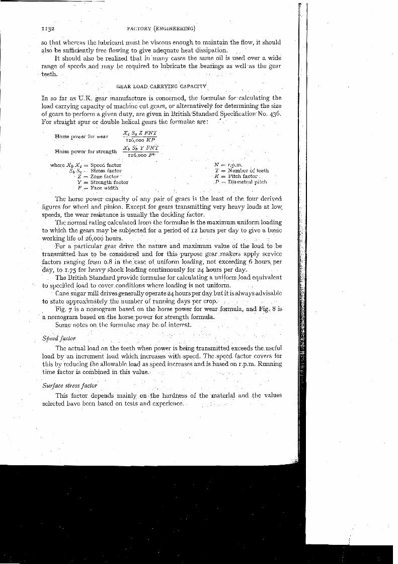
Alternatively, a mechanical lubricating system can be used as in Fig. 10. This comprises a radial pump unit driven by electric motor through a reduction gear box. I t is suitable for either grease or oil.
\
Each such pump unit can deliver a pre-determined quantity of oil or grease to 19 bearings through an independent pumping unit actuated by a cam through a worm reduction gear. The effective stroke can be reduced in stages from full stroke to zero.
Mention should also be made of the familiar ring oil lubrication system and the centralized systems using distribution blocks to cover a multiplicity of bearings.
Fig. g. Lubrication by return-flood system.
Plain bearings are often used in high-speed turbine reduction gear boxes for high-speed work coupled with heavy loading. Forced lubrication is generally used in such cases.
Fig. 11 illustrates a system for lubricating gears and bearings in a totally enclosed gearbox. The system includes, reservoir tank pumps, filters, pressure switches, flow indicators, pressure gauges, thermometer, pressure regulator, etc. If required, heaters, coolers and thermostatic controls can be fitted.
Anti-friction or roller bearings
Although ball and roller bearings have been in use in sugar factories for many years on such applications as pump shafts, cane-knife shafts, and, in isolated cases, mill-gear drives, their general applications to gear shafts is a comparatively recent one stimulated undoubtedly by the advent of the turbine drive with its associated self-contained gear unit. Their benefits may be briefly summarized as follows:
Wear on shaft journals is eliminated as the bearing inner races afford protection. Saving in power due to lower friction co-efficient as compared with plain bearings.
A. W. P. MCNEE
Fig. 10. Mechanical lubrication system.
Fig. 11. Lubricating system for a totally enclosed gearbox.
Less wear on gears as the relative shaft positions remain constant due to small clearance in the bearings and their freedom from wear.
Simplified lubrications; in many cases bearings can be prepacked with grease and thereafter require little attention.
Saving in size and weight as shorter shafts can be used. The selection of a suitable bearing for a given application is a specialized task
and often requires consultation between gear makers and bearing manufacturers. Two main types are used in mill gear drives. Spherical roller bearings which are
suitable for axial as well as radial loads but are limited by speed; and cylindrical roller bearings which are suitable for high speeds but deal with radial loads only.
Depending on their location and duty, cylindrical bearings may be free (for radial loads only), locating (locates the shaft but not designed to withstand thrust), or fitted with a grooved race (for combined radial and axial loads).
Spherical roller bearings have self-aligning properties and cylindrical roller bearings can be contained in self-aligning housings to achieve this property.

Spherical roller bearings are often mounted on withdrawal sleeves to facilitate fitting and dismantling.
With large bearings using adapter or withdrawal sleeves oil injection is sometimes used for mounting and dismounting.
Split cylindrical roller bearings can be used where the bearings, housings, pedestal bases, and caps are made in halves. This facilitates assembly and the rolling surfaces can be readily inspected by simply taking the weight of the bearings without appreciable lift.
Such bearings are available in sizes up to 24" diameter carrying loads of up to about 750,000 lb. depending op speed of shaft.
Due to the wide range of speeds in mill-gear drives it is inevitable that various sizes of bearings are required through the train. In the selection of the bearings some effort should be made to standardize to avoid the necessity of carrying a wide assortment of spares. Due to the high cost of the bearings in the larger sizes this may not be economical and it may be that in a number of arrangements a combination of plain bearings and anti-friction bearings may be the most desirable arrangement using anti-friction bearings in standard sizes which inay be stocked by local distrib- utors.
Care must obviously be taken in the maintenance of such an arrangement as the plain bearings will wear and may affect gear meshing. This would only be serious if different types were used on the same shaft.
I
GEAR FAILURE I
Provided gears are adequately proportioned for their duty, manufactured in suitable materials, having ample strength and have teeth of correct form and accurately produced, and are properly supported and lubricated, they will give long and satisfac- tory service. I t is recommended that the gears should be 'run in' for a period under light load before being subjected to full load. This will allow any high or hard-bearing spots to be reduced and properly polished tooth surfaces will be obtained.
Where gear failure does occur, it usually takes the form of partial or total destruc- tion of the tooth faces, or partial or total fracture of the teeth.
Surface failures may be classified as follows:
A brasion
Where abrasion shows as scratches from the tips to the base of the teeth, it is generally a sign of foreign matter in the lubricant.
Where an unsuitable oil is used, or the gear material is of insufficient surface hardness, rapid wear takes place, although the tooth surface ,may remain relatively smooth. It 1 Scufing and scoving
This is usually caused by total failure of the oil supply, or a rupture of the oil film, allowing metal-to-metal tooth contact giving high local temperatures resulting in torn metal. The resultant score marks run in the direction of sliding motion. This is often cured by the use of extreme-pressure oils.

A. W. P. MCNEE 1139
Ridging
This appears similar to scuffing, but the metal flows; whereas with scuffing failures the metal is torn. This will show up as grooves on the driving member and ridges on the driven member, near the pitch line, and, is invariably caused by overloading or perhaps unsuitable material.
Pitting
This is quite a distinctive failure and shows up as a number of small cavities in the tooth faces and often occurs soon after the initial start-up, due to initial high spots in the teeth or slight misalignment. In this case, it tends to disappear once the gears have been properly run in. When it is severe, the cause is generally overload or severe misalignment, either by shaft deflection or improper lining up and may result in the forination of cracks and subsequent fracture.
Cracking and JEaking
This occurs generally in the case of surface-hardened gears and is usually caused by faulty hardening or faulty material.
Tooth blteakages
If the breakage is sudden, it is invariably the result of the entry 01 some foreign body between the teeth. Gradual breakages may be caused by repeated overload or unsuitable material, and in this case, a crack generally forms near the root and extends until a part of the tooth breaks away. This is a fatigue fracture and can easily be identified as a crack exists for some time before breakage takes place.
SUMMARY
Various arrangements of mill geaiing arc illustrated covering single and multiple mill drives in colnbinatioils using straight spur and double helical gears. Brief mention is made of the method of inanufacture and the materials used.
General design featules are considered and suitable lubrication systems illustrated. Noinograins are included (based on the British Standard Specification for gear loading
capacity), wlncl~ facilitate horse-power calculations. The use of plain or roller type bearings on gear shafts is discussed, and finally some causes
of typlcal gear fall~ues are described.
DISCUSSIONS
S. G. CLARICE (Australia) : Why are gears designed to BSS generally smaller than those designed according to the American standards ?
A. W. P. MCNEE (U.K.) : Horsepower rating of British gears is based on the lowest figure ih the four calculations involved. This is usually the figure for wear. Generally, the corresponding stiength figure is twice as high.
MR. CLARKE: What is tge maximum peripheral speed which can be used with well machined , straight spur gears ?
MR. MCNEE. 2100 to 2600 ft. lmin is ~enerallv acce~ted. " MR. CLARICE: Does the British Standard allow for the correction of gears in all cases or
oilly on gears below 17 teeth as stated in the paper ? MR. MCNEE: Correction is talcen into account in the BSS in all cases. MR. CLARICE: Does the British Standard allow for the use of surface hardened pinions with
normal cast steel gears ? MR. MCNEE: I t is quite feasible to use a hardened pinion. In fact pinions should be generally
of hard wearing material, because the contact time of the pinion is equal to the contact time of the wheel inultiplied by the gear ratio.

f
G. BAX (Mauritius) : Is there any special arrangement for lubricating plain bearings when there is a rising pinion ?
MR. MCNEE: I do not think that special arrangements are necessary for lubrication, but the containing caps and bolts should be strengthened.
MR. BAX: Should oil entry always be on the top ? MR. MCNEE : Yes. M. PATURAU (Mauritius): In view of the high quality of modern high pressure lubricants
now available, is not the wear factor used for spur gears slightly pessimistic ? MR. MCNEE: This is possibly true.