a wideband rectangular-slot microstrip array antenna...
TRANSCRIPT
A Wideband Rectangular-slot Microstrip Array
Antenna for Wireless Applications
Obeng Kwakye Kingsford Sarkodie
Abstract—This paper presents the design of a 2 x 2 microstrip
array antenna suitable for wireless applications. The proposed
antenna comprises of 4 rectangular patches where diagonal patches
have the same length and width. A larger bandwidth and the desired
resonant frequency are achieved because of a reduction in the quality
factor (Q) of the patch resonator, which is due to less energy being
stored beneath the patch due to the rectangular arrangement of the
slots. The characterization results of return loss, gain, and radiation
pattern are presented consecutively. From the results, the simulated
impedance bandwidth defined for S11<-10dB reaches 1850MHz
(4.69-6.54GHz) representing 16.47%.
Keywords— wideband, array antenna, slot, patch, wireless
I. INTRODUCTION
ICROSTRIP antennas have been popular for decades
because they exhibit a low profile, small size,
lightweight, low manufacturing cost, high efficiency,
and an easy method of fabrication and installation.
Furthermore, they are generally economical to produce since
they are readily adaptable to hybrid and monolithic integrated
circuits fabrication techniques at radio frequency (RF) and
microwave frequencies [1]. One of the most important
disadvantages of microstrip patch antenna is their narrow
bandwidth. To overcome this problem and for the antenna to
work within a stipulated band, a number of methods and
structures have recently been proposed. Mention can be made
of wideband aperture coupled microstrip array antennas [2],
U-slot with proposed π-shaped stub [3], double rectangular
patch with bridges [4], stacked layered structures [5],
resonator antennas with capacitive coupled parasitic patch
element [6], circular edge truncation [7].
This paper presents a wideband 2 x 2 rectangular slot
microstrip antenna which covers the WLAN band. WLAN
takes advantage of license free frequency bands, industrial,
scientific, medical (ISM) bands and uses one of frequency
band 5.15 to 5.825 GHz (IEEE 802.11a) [8]. Since WiMAX
has three allocated frequency bands called low band (2.5 GHz
to 2.8 GHz), middle band (3.2 GHz to 3.8 GHz), and high
band (5.2 GHz to 5.8 GHz), the proposed antenna is also
applicable to WiMAX. The impedance bandwidth in
percentage is 16.47% which is far higher than that of [4] who
compared double rectangular patch with 4 bridges for 2.4GHz
and 5.5GHz WLAN applications.
Obeng Kwakye Kingsford Sarkodie is a PhD Student at the University of
Electronic Science and Technology of China, China, Chengdu, Sichuan.
(Email: [email protected])
It also has a higher bandwidth than [8] and [9] who recorded 14% for WiMAX and 14.1% for WLAN applications respectively.
II. ANTENNA CONFIGURATION
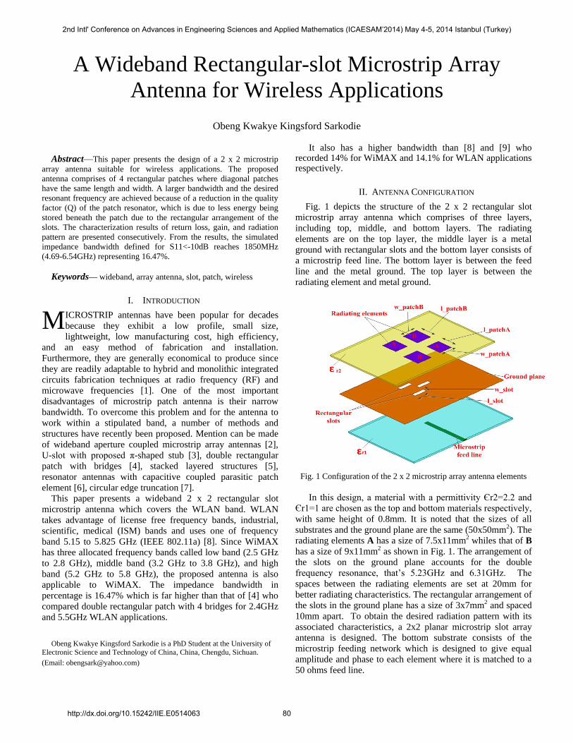
Fig. 1 depicts the structure of the 2 x 2 rectangular slot
microstrip array antenna which comprises of three layers,
including top, middle, and bottom layers. The radiating
elements are on the top layer, the middle layer is a metal
ground with rectangular slots and the bottom layer consists of
a microstrip feed line. The bottom layer is between the feed
line and the metal ground. The top layer is between the
radiating element and metal ground.
Fig. 1 Configuration of the 2 x 2 microstrip array antenna elements
In this design, a material with a permittivity Єr2=2.2 and
Єr1=1 are chosen as the top and bottom materials respectively,
with same height of 0.8mm. It is noted that the sizes of all
substrates and the ground plane are the same (50x50mm2). The
radiating elements A has a size of 7.5x11mm2 whiles that of B
has a size of 9x11mm2 as shown in Fig. 1. The arrangement of
the slots on the ground plane accounts for the double
frequency resonance, that’s 5.23GHz and 6.31GHz. The
spaces between the radiating elements are set at 20mm for
better radiating characteristics. The rectangular arrangement of
the slots in the ground plane has a size of 3x7mm2 and spaced
10mm apart. To obtain the desired radiation pattern with its
associated characteristics, a 2x2 planar microstrip slot array
antenna is designed. The bottom substrate consists of the
microstrip feeding network which is designed to give equal
amplitude and phase to each element where it is matched to a
50 ohms feed line.
M
2nd Intl' Conference on Advances in Engineering Sciences and Applied Mathematics (ICAESAM’2014) May 4-5, 2014 Istanbul (Turkey)
http://dx.doi.org/10.15242/IIE.E0514063 80
III. RESULTS
The array antenna is simulated using the commercial Ansoft
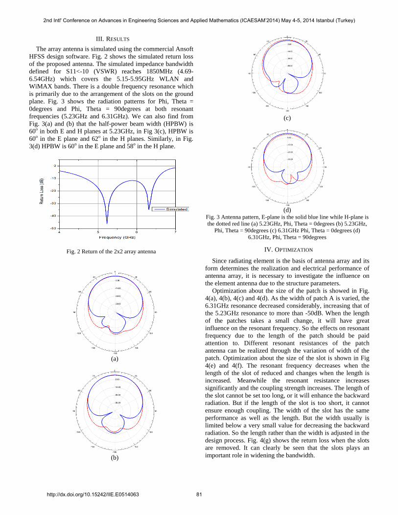
HFSS design software. Fig. 2 shows the simulated return loss
of the proposed antenna. The simulated impedance bandwidth
defined for S11<-10 (VSWR) reaches 1850MHz (4.69-
6.54GHz) which covers the 5.15-5.95GHz WLAN and
WiMAX bands. There is a double frequency resonance which
is primarily due to the arrangement of the slots on the ground
plane. Fig. 3 shows the radiation patterns for Phi, Theta =
0degrees and Phi, Theta = 90degrees at both resonant
frequencies (5.23GHz and 6.31GHz). We can also find from
Fig. 3(a) and (b) that the half-power beam width (HPBW) is
60o in both E and H planes at 5.23GHz, in Fig 3(c), HPBW is
60o in the E plane and 62o in the H planes. Similarly, in Fig.
3(d) HPBW is 60o in the E plane and 58o in the H plane.
Fig. 2 Return of the 2x2 array antenna
(a)
(b)
(c)
(d)
Fig. 3 Antenna pattern, E-plane is the solid blue line while H-plane is
the dotted red line (a) 5.23GHz, Phi, Theta = 0degrees (b) 5.23GHz,
Phi, Theta = 90degrees (c) 6.31GHz Phi, Theta = 0degrees (d)
6.31GHz, Phi, Theta = 90degrees
IV. OPTIMIZATION
Since radiating element is the basis of antenna array and its
form determines the realization and electrical performance of
antenna array, it is necessary to investigate the influence on
the element antenna due to the structure parameters.
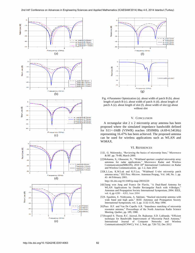
Optimization about the size of the patch is showed in Fig.
4(a), 4(b), 4(c) and 4(d). As the width of patch A is varied, the
6.31GHz resonance decreased considerably, increasing that of
the 5.23GHz resonance to more than -50dB. When the length
of the patches takes a small change, it will have great
influence on the resonant frequency. So the effects on resonant
frequency due to the length of the patch should be paid
attention to. Different resonant resistances of the patch
antenna can be realized through the variation of width of the
patch. Optimization about the size of the slot is shown in Fig
4(e) and 4(f). The resonant frequency decreases when the
length of the slot of reduced and changes when the length is
increased. Meanwhile the resonant resistance increases
significantly and the coupling strength increases. The length of
the slot cannot be set too long, or it will enhance the backward
radiation. But if the length of the slot is too short, it cannot
ensure enough coupling. The width of the slot has the same
performance as well as the length. But the width usually is
limited below a very small value for decreasing the backward
radiation. So the length rather than the width is adjusted in the
design process. Fig. 4(g) shows the return loss when the slots
are removed. It can clearly be seen that the slots plays an
important role in widening the bandwidth.
2nd Intl' Conference on Advances in Engineering Sciences and Applied Mathematics (ICAESAM’2014) May 4-5, 2014 Istanbul (Turkey)
http://dx.doi.org/10.15242/IIE.E0514063 81
(a)
(b)
(c)
(d)
(e)
(f)
(g)
Fig. 4 Parameter Optmization (a). about width of patch B (b). about
length of patch B (c). about width of patch A (d). about length of
patch A (e). about length of slot (f). about width of slot (g) about
without slot
V. CONCLUSION
A rectangular slot 2 x 2 microstrip array antenna has been
proposed where the simulated impedance bandwidth defined
for S11<-10dB (VSWR) reaches 1850MHz (4.69-6.54GHz)
representing 16.47% has been achieved. The proposed antenna
can be used for wireless applications such as WLAN and
WiMAX.
VI. REFERENCES
[1] L. G. Maloratsky, “Reviewing the basics of microstrip lines,” Microwave & RF. pp. 79-88, March 2000.
[2] Mohanna, S,; Ghassemi, N., “Wideband aperture coupled microstrip array antennas for radar applications,” Microwave Radar and Wireless Communications(MIKON), 2010 18th International Conference on Radar and Wireless Communications. pp. 1-2, June 2010
[3] K.L.Lau, K.M.Luk and K.F.Lee, ”Wideband U-slot microstrip patch antenna array,” IEE Proc.-Microw. Antennas Propag., Vol. 148, No. 1. pp. 41- 44 February 2001.
http://dx.doi.org/10.1049/ip-map:20010220
[4] Chang won Jung and Franco De Flaviis, “A Dual-Band Antenna for WLAN Applications by Double Rectangular Patch with 4-Bridges,” Antennas and Propagation Society International Symposium, 2004. IEEE, vol. 4, pp 4280 – 4283, June 2004
[5] S. Egashira, E. Nishiyama, A. Sakitani, “Stacked microstrip antenna with wide band and high gain,” IEEE Antennas and Propagation Society International Symposium, vol. 3, pp. 1132-1135, May 1990.
[6] Pues H.F. and Van De Capelle A.R. “Impedance matching of microstrip resonator antenna,” Proceedings of the North American Radio Science Meeting, Quebec, pp. 189, 1980.
[7] Swapnil S. Thorat, R.C. Jaiswal, Dr. Rajkumar, S.D. Lokhande, “Efficient technique for Bandwidth Improvement of Microstrip Patch Antenna,” International Journal of Computer Networks and Wireless Communications(IJCNWC), Vol. 2, No6, pp. 728-732, Dec 2012
2nd Intl' Conference on Advances in Engineering Sciences and Applied Mathematics (ICAESAM’2014) May 4-5, 2014 Istanbul (Turkey)
http://dx.doi.org/10.15242/IIE.E0514063 82

[8] Amir Reza Dastkhosh and Hamid Raza Dalili Oskouei, “A wideband High-Gain Dual-Polarized Slot Array Patch Antenna for WiMAX Applications in 5.8GHz, “International Journal of Antennas and Propagation, vol. 2012, Article ID 595290, 6pages 2012.
[9] Chao Sun; Jiu-sheng Li, “A novel planar microstrip array antenna for WLAN applications,” Microwave, Antenna, Propagation, and EMC Technologies for Wireless Communications (MAPE), pp. 16-17, Nov 2011
Obeng Kwaye Kingsford
Sarkodie (S’14) was born in Kumasi, Ghana in 1986. He received the B.S degree from the Kwame Nkrumah University of Science and Technology, Kumasi, Ghana in 2009. He received the M.S degree from the University of Electronic Science and Technoly of China in 2012, where he is currently working toward the PhD degree. Prior to his continuing education at the University of Electronic Science and Technolgy of China, he was a
teaching assistant at the Kwame Nkrumah University of Science and Technolgy, Kumasi, Ghana.
His research interests includes electromagnetic fields in layered media, Sommerfeld integrals and microstrip array antennas.
2nd Intl' Conference on Advances in Engineering Sciences and Applied Mathematics (ICAESAM’2014) May 4-5, 2014 Istanbul (Turkey)
http://dx.doi.org/10.15242/IIE.E0514063 83