a windows program for airfoil design using b-splines
TRANSCRIPT

Rochester Institute of Technology Rochester Institute of Technology
RIT Scholar Works RIT Scholar Works
Theses
1999
A Windows program for airfoil design using B-splines A Windows program for airfoil design using B-splines
Matthew MacLean
Follow this and additional works at: https://scholarworks.rit.edu/theses
Recommended Citation Recommended Citation MacLean, Matthew, "A Windows program for airfoil design using B-splines" (1999). Thesis. Rochester Institute of Technology. Accessed from
This Thesis is brought to you for free and open access by RIT Scholar Works. It has been accepted for inclusion in Theses by an authorized administrator of RIT Scholar Works. For more information, please contact [email protected].

A Windows Program for Airfoil Design
Using B-Splines
by
Matthew G. MacLean
A Thesis Submitted in Partial Fulfillment of the Requirement for
the
MASTER OF SCIENCE
IN
MECHANICAL ENGINEERING
Approved by:
Dr. P. N. VenkataramanDepartment of Mechanical Engineering
Dr. K. B. KochersbergerDepartment ofMechanical Engineering
Dr. A. D. OgutDepartment ofMechanical Engineering
Dr. C. HainesDepartment ofMechanical Engineering
•
(thesi s advisor)
(department head)
DEPARTMENT OF MECHANICAL ENGINEERINGROCHESTER INSTITUTE OF TECHNOLOGY
AUGUST 1999

Permission Granted
I, Matthew G. MacLean, hereby grant permission to the Wallace Library of the Rochester
Institute ofTechnology to reproduce my thesis in whole or in part. Any reproduction will
not be for commercial profit.
Signature of author:
Date:

Special Thanks
I would like to thank my advisors for their academic inspiration:
Dr. Venkataraman, Dr. Kochersberger, Dr. Ogut, and Dr. Haines.
I would also like to thank my parents for their financial and moral support throughout my
college career.
I would like to thank Phi Delta Theta International Fraternity for the inspiration and
chivalrous character it has allowed me to develop and build in myself.
I would like to thank a few ofmy closest friends who have taken an interest in my progress
on this thesis, and their willingness to help in any way they could:
Bean, Yako, Odie, Snarf, Hollywood, Reno, Philo, Rivet, Dinger, Nermal, Fizzgig,
and Lodor.
Finally, I would like to thank all ofmy friends that I have known throughout my college
career (and will continue to know)- the people who have made it easier to do everything I
have done at RIT:
Caleo, Sean, Rob, Todd G., Nutter, Kevin, Kelly, AndrewW., Stu, Mellors, Matt R.,
Steinberg, Tom K, Mole, Jeff, Wonka, Tony, Wedge, Nuck, Point, Grout, Clint,
Bones, Pugsley, Waldo, Shipwrek, Elmo, Potash, Gonzo, Starch, Ollie, Ludo, Fletch,
Lurch, Dan. H, Binford, Rooney, Hatch, Fozzy, Dreggs, Kodiak, Snuff, Liam, Juggs,
McGruff, Donk, Quark, Shifty, Kroger, Ed Steffens, Amanda, Jen-Jen, Jen D., Dance
Party, Ken O., Laura E., Nicole, Karen, Jenn G., Marlene, Linus, Moose, Gummer,
Doogie, Kazoo, and Pugsley.

For all those on the previous page that this is dedicated to:
'Time is a companion thatgoeswithus on
the journey* and reminds us to cherish
everymoment, because they'll never
come again. Whatwe leave behind is
not as important as howwe'velived/'
- Patrick Stewart, Star Trek: Generations.

Abstract
The objective of this thesis has been threefold. First, the formulation of splines
has been studied and their development into a computer algorithm has been implemented.
Splines represent a powerful concept in computer modeling and geometric representation,
for, as parametric curves, they provide a compact way to store the information defining a
curve or surface. B-splines have been exclusively used in this thesis, although other
types of splines exist.
The second goal of this thesis was to learn and utilize C++ as a programming tool
in the demonstration ofB-spline techniques. C++ was chosen because it is object-
oriented, and because it is the chosen language oftheMicrosoft Windows PC platform.
Many languages are object-oriented, but C++ was chosen to make use of its libraries to
build standardWindows interfaces and objects.
The third piece of this thesis is an effort to explore the fundamentals of inter-
language communications. Many old scientific codes are already written in older
languages like FORTRAN, so it is advantageous to re-use those codes where possible.
Digital Visual FORTRAN, a module of theMicrosoft Visual Studio, has provided a
powerful tool in their integration ofmultiple programming languages for Windows
applications. Using Visual Studio, it is possible to re-use existing FORTRAN code and
envelop it in a C interface using a dynamic link library (DLL) file.
This thesis uses a C++ application for defining any typical airfoil using B-splines.
The software package calls XFOIL, a code written in FORTRAN to evaluate the
aerodynamic characteristics of those airfoils. Further, those characteristics have been
compared to those of the original geometry to evaluate the interpolation process used by
the splines.

Table of Contents
1 .0 Introduction to B-spline 1
1 . 1 B-splines 1
1 .2 Matrix Form of Splines 10
1 .3 Curve Approximation with B-splines 1 1
2.0 Selected Topics ofC++ 13
2.1 Structures 14
2.2 Classes 15
2.3 Inheritance 21
2.4 Polymorphism 23
2.5 Pointers and Arrays 24
2.6 Multi-dimensional Arrays 29
3.0MFC programming in C++ 38
3 . 1 The CWinApp and CMainWnd Objects 40
3 .2 Message Maps 42
3.3 Resources 46
3.4Wizards 52
4.0 Advanced Coding and Modularization 54
5.0 A Description of the Progranirning Algorithms used 62
6.0 Results 67
7.0 Conclusion/Recommendations 81
Reference List 83
Main program source files A-l
Data reading source files B-l

List of Figures
1 A Typical Spline Curve 2
2 Plot ofExample 1 5
3 Plot ofExample 3 9
4 Memory Mapping Configuration 27
5 Multidimensional Array Mapping 34
6 2-Dimensional Array Mapping 35
7 1-Dimensional Array Mapping 35
8 A Typical Dialog Box 47
9 Data Read Utility Program(main window) 67
10 Standard Windows 95/NT Open File Dialog Box 68
1 1 Airfoil Spline Program 68
12 New Airfoil Dialog Box 69
13 Spline Airfoil Program withN0012 Airfoil Active 70
14 Typical Polygon Point Box 71
15 N0012 Airfoil Comparison 73
16 N241 1 Airfoil Comparison 73
17 Selig 1223 Airfoil Comparison 74
1 8 Boeing 707 0.54 Span Airfoil Comparison 74
19 RAE(NPL) 5215 Airfoil Comparison 75
20 civs, a for N2411 Airfoil 79
21 cdvs. a forN24 11 Airfoil 79

List of Tables
1 NACA 0012 Airfoil 76
2 NACA 2411 Airfoil 76
3 Selig 1223 Airfoil 76
4 Boeing 707 Airfoil 76
5 RAE(NPL) 5215 Airfoil 76
6 NACA 0012 Airfoil 77
7 NACA 2411 Airfoil 77
8 Selig 1223 Airfoil 77
9 Boeing 707 Airfoil 77
10 RAE(NPL) 5215 Airfoil 77
11 RAE(NPL) 5215 Airfoil 78
12 Bezier Curve Tests 80

1.0 Introduction to B-splines
The word spline is a generic term used to describe a vast family ofmathematical
curves with a variety ofproperties, behaviors, and characteristics. Splines are piecewise
polynomials, meaning that they are defined differently at various points along their length.
This thesis uses generic B-type splines.
Although not specifically used in this thesis, one important type ofB-splines is
known as the non-uniform rational B-spline (NURBS). NURBS are used by many
commercial software programs, especially for defining CAD geometry. They are also often
utilizes by three-dimensional modeling and drawing programs. NURBS are also important in
the field ofmulti-disciplinary design; they possess the compactness of all splines, and their
implementation gives them flexibility while remaining stable and simple to control. This
thesis has implemented generic B-splines to investigate their potential for similar
applications.
A description ofB-splines and their creation and implementation is provided in this
section. A special subset ofB-splines called Bezier curves will also be introduced. Several
examples of splines will be given. After the method of calculating them is explained, the
analytical representation ofcurve fitting B-splines is developed. This method does not
employ an approximate fit but rather interpolates from the data directly. The Airfoil Spline
Application program, the source code provided in Appendix A, makes use of this method in
creating airfoils for submission to XFOIL.
1.1 B-splines
B-splines are parametric curves governed by a set of equations known as the de Boor
recursion formulas. The curve is actually in terms ofa parametric variable /, which is
converted to the classic x,y,z Cartesian coordinates through a set ofdefining polygon points.
The number ofdimensions of the curve is directly determined by the number ofdimensions
of the polygon points since each dimension is calculated independently. This set ofdefining
points are referred to as such because they can all be connected to form a polygon with as
many sides as there are points.
page- 1

An interesting property ofB-splines is that the curve will generally follow the
polygon points in space. It should be noted here that the defining polygon points do not
necessary have to follow a particular ordered sequence in space (for example, in order of
increasing x coordinate); these points can lie in any order desired, and the curve will follow
that spatial pattern. The curve can even intersect or cross over itself. Figure 1 shows a
typical B-spline with the defining polygon outlined.
Figure 1. A Typical Spline Curve
The actual formulas themselves are given as follows, taken from Reference [1]:
n+l
J>(0 =V*W) (D
where P(t)=
[x(t) y(t) z(t) JandB=
[Bx By BZJ.
page -2

Nil(') ={1 tf X'-t<X,+l (2)
'
0 otherwise
=_____i+______i (3)
In equations (1) - (3), there are several symbols that need to be defined. First, in
equation (1), the B term represents the polygon points. These points are designated asBl
throughB5 in Figure 1, and are known as polygon points, vertex points, polygon vertices,
control points, etc. The data point of the curve is just a summation of these polygon points
times a shape factor associated with each one. Since the data point, P(t), and the polygon
points are both vectors, the data point can be calculated one dimension at a time. The
summation ofBxs times their shape factors yields the resultingx-value of the data points.
The x-terms in equations (2) and (3) are the terms of a knot vector. They are not
related to the Cartesian coordinate x. This knot vector adds an interesting twist to this type of
mathematics, as the knot terms determine how far a polygon vertex's influence extends
through the curve. These knot vector terms appear in both equation (2) and (3), which
determines the value of the shape factors. This, in turn, controls the influence a particular
polygon point has at different data locations along the spline. A spline generally follows its
polygon shape because of this -
points close to a particular data location have more control
and can pull the data toward it. The only requirement for knot vector terms is that each
successive term must be greater than or equal to the previous term.
The lower case n is related to the number of control points that determine the curve
There must always be one more than n polygon points to control the spline. For instance, in
the case ofFigure 1, there are five control points (Bl throughB5), so n equals 4 for that
particular spline. Additionally, k is called the curve order. The third equation (3) must be
iterated successively until the k level is found. This directly defines the order of the
polynomial shape factors, which are just parametric polynomial curves of the variable t. As
with all polynomials, a higher order shape factor allows for more complex curvatures and
fitting. It works out that the knot vector must always have n+k+1 terms in it to satisfy the
formulations in (1) through (3).
page -3

It seems appropriate to help clarify this process ofcurve generation with a simple
example carried out by hand to generate a B-spline.
Example #1: generation of formulas for a B-spline with specified parameters.
specified - n= 3 (control points)
k = 4 (curve order)
3= [0 0 0 0 1 1 1 1] (knot vector - n+k+1 terms)
Bj = (0, 0) B2 = (1, 1) B3 = (2, 1)
B4 = (3, 0) (control point coordinates)
For B-spline generation, n, k, the knot vector, and the polygon vertices
must be defined. They have been chosen for this example as shown.
shape factor calculation -
for0<t< l,k=l:
Nn = 0 N2i = 0 N3i = 0 N4i = l N5i = 0
N61 = 0 N71 = 0
for0<t< l,k=2:
Ni2 = 0 N22 = 0 N32 = (l-t) N42 = t
N52 = 0 N62 = 0
for0<t < l,k=3:
Ni3 = 0 N23 =(l-t)2
N33 = 2t(l-t)
N43 =t2
N53 = 0
for0<t< l,k=4:
N14 =(l-t)3
N24 =3t(l-t)2
N34 = 3t2(l-t)
N44 =t3
curve equation-
P(t)= B,
*N14 + B2
*N24 + B3
*N34 + B4
*N44
P(t)= Bi
* (1 -
t)3
+ 3 *B2
*t* (1 -
t)2
+ 3 *B3
* t2 * (1 -
t) + B4* t3
Px = 0 * (1 -
t)3
+ 3 * 1 *t* (1 -
t)2
+ 3 * 2 * t2 * (1 -
t) + 3* t3
Py= 0
* (1 -
t)3
+ 3*
1*t* (1 -
t)2
+ 3 *1* t2 * (1 -
1) + 0 * t3
page -4

1
0.9 -
0.8 -
0.7 -
0.6 -
>0.5 -
0.4 -
0.3 -
0.2 -
0.1 -
n 4
~-^^
spline
vertices
C) 0.5 1 1.5 2 2.5 2
X
I
Figure 2. Plot ofExample 1
There are a variety of things that should be noted in looking at Example 1. First, the
equations are defined from 0 < / < 1 . From equation (2), this can be seen as the only range
for which any shape factor will take on a non-zero value. Hence, / will always range
between the first knot vector term value and the last knot vector term value.
Second, the spline starts at the first polygon vertex and ends at the last polygon
vertex. This is not true ofall B-splines, but is determined by the selection of the knot vector.
This selection will be discussed further later. The range for t is technically specified not to
include the value of / = 1. For this particular example, that corresponds to the Cartesian
point (3,0). This point is typically included on the end ofthe final definition range to allow
the curve to touch the final vertex point for practical reasons. The last /-range is made a less
than or equal to condition rather than simply less than.
The knot vector used in Example 1 was chosen for simplicity. The /-variable was
defined uniformly throughout its entire range. With a more complicated knot vector, there
may be several ranges in which t is defined differently in each. Such an example will be seen
in Example 3.
Bezier curves are a special subset ofB-splines; a Bezier curve is a B-spline with k
equal to n+J, and an open, uniform knot vector. An open, uniform knot vector is one with k
terms that are identical on each end ofthe vector. The knot vector from Example 1 is such an
page -5

entity. With n=3, and k=n+l=4, there are eight terms in the knot vector. This knot vector
starts with 4 identical terms, and ends with 4 identical terms. Usually, these terms are zero
and one respectively formathematical simplicity, although they could take on any value as
long as they meet the condition above. Hence, Example 1 was actually a Bezier curve.
The B-spline formulas can be greatly simplified for Bezier curves. This is what
makes them so popular. The Bezier formulation is given as follows:
P(t) =BiJn4 (4)1=0
^,,=rT7i!L7/a-'r (5)f!(-/)!
The notation here has been kept the same as in reference [1], which starts numbering the
vertices with zero for a Bezier curve. In dealing with these formulations, (1) through (5), the
first vertex of a B-spline starts withBl while the same first vertex using the Bezier curve
formulas begins with JO.
Example #2: generation of a B-spline curve using Bezier formulas.
specified - n= 3
k = 4
B0 = (0,0) B, = (l, 1) B2 = (2, 1) B3 = (3,0)
Note that there is no knot vector specified (it is implied in the
formulation to be halfzeros and halfones- [ 0 0 0 0 1 1 1 1]).
shape factor calculation -
J3,o = 6/6* t * (1-t)3 =
(1-t)3
J3,i = 6/2* t1 * (1-t)2 = 3 t
(1-t)2
J3)2 =6/2*t2*(l-t)1
=3t2(l-t)1
J3,3 =6/6*t3*(l-t)
=3t3
curve equation-
P(t)= B0
*J30 + Bi
*J3i + B2
*J32 + B3
*J33
P(t)= B0
* (1 -
t)3
+ 3 *Bi
*t* (1 -
t)2
+ 3 *B2
* t2 * (1 -
t) + B4* t3
page -6

Px = 0 * (1 -
t)3
+ 3 * 1 *t* (1 -
t)2
+ 3* 2 * t2 * (1 -
1) + 3 * t3
Py= 0 * (1 -
t)3
+ 3 *1 *
t* (1 -
1)2
+ 3*
1* t2 * (1 -
t) + 0 * t3
The curve equations are, ofcourse, identical to those found in example #1, illustrating
that the two sets of formulas are interchangeable. The main advantage of the Bezier subset is
its simplicity of formulation. The disadvantage here, however, is that the curve is made up of
only one section; hence, any changes to one of the defining polygon points have a global
impact on the shape of the entire curve. General B-splines have the advantage of local
control. As will be shown in Example 3, the knot vector can be selected to cause the curve to
be defined in multiple sections, each defined by only the vertices in that area. A change to
one of those vertices has absolutely no effect on the other sections of the curve. This allows
for more precise curve control and can be exploited to develop much more complex
geometries and features.
On a related note, it was mentioned previously that a generic B-spline does not
necessarily have to connect to the two end vertices. An open knot vector causes it to connect
to the two extreme vertices, rather than hanging freely in space. The Bezier curve utilizes an
open knot vector which is also uniform. Example 3 will also utilize an open knot vector, but
k will not equal n+ 1 as in a Bezier curve. There are obviously many applications where it
will be prudent to make use of an open knot vector to better predict the curve shape.
Example #3: generation of formulas for a B-spline with an open uniform knot vector.
specified - n= 4
k = 3
3= [0 0 0 1 2 3 3 3]
B,=(0,0) B2 = (l, 1) B3 = (2, 1) B4 = (3,2) B5 = (3, 0)
An open knot vector is used, although this is NOT a Bezier curve.
shape factor calculation-
N3i = 1 N4] = 0 N5i = 0
for0<t < l,k=l:
Nn = 0 N2i = 0
N61 = 0 N7i = 0
for0<t < l,k=2:
page -7

Ni2 = 0 N22=l-t N32 = t N42 = 0 N52 = 0
N62 = 0
forO<t< l,k=3:
N13 =(l-t)2
N23 = t(l-t) + 0.5t(2-t) N33 =0.5t2
N43= 0
N53 = 0
fori <t<2,k=l:
Nn = 0 N2i = 0 N3i = 0 N41 = l N5i=0
N6i = 0 N71 = 0
for 1 < t < 2, k=2:
N12 = 0 N22 = 0 N32 = 2 - 1 N42 = t - 1 N52 = 0
N62 = 0
for 1 < t < 2, k=3:
N13 = 0 N23 = 0.5 (2 -
t)2
N33 = 0.5 t (2 -
t) + 0.5 (3 - t)(t - 1) N43 = 0.5 (t -
l)2
N53 = 0
for2<t<3, k=l:
Nn = 0 N2i = 0 N3i=0 N41=0 N5i = l
N6X = 0 N71 = 0
for 2 < t < 3, k=2:
Ni2 = 0 N22 = 0 N32 = 0 N42 = 3-t
N52 = t - 2 N62 = 0
for2<t<3, k=3:
Nn = 0 N23 = 0 N33 = 0.5 (3 -
t)2
N43 = 0.5 (t - 1)(3 -
1) + (3 - t)(t - 2) N53 = (t -
2)2
curve equation-
P(t)= Bi
*Ni4 + B2
*N24 + B3
*N34 + B4
*N^ +
B5*N54
0</<l >
P(t)= Bi
* (1 -
t)2
+ B2* [t * (1 -
t) + 0.5 *t* (2 -
t)] + B3*0.5 * t2
Px = 0 * (1 -
1)2
+ 1 * [t * (1 -
t) + 0.5 *t* (2 -
1)] + 2 *0.5 * t2
Py= 0 * (1 -
t)2
+ 1 * [t * (1 -
1) + 0.5 *t* (2 -
t)] + 1 * 0.5 * t2
l<r<2 >
page -8

P(t)= B2
*0.5 * (2 -
t)2
+ B3* [0.5 *
t* (2 -
1) + 0.5 * (3 -
1)* (t - 1)]
+B4*0.5*(t-1)2
Px= 1 *0.5 * (2 -
t)2
+ 2 * [0.5 *t* (2 -
t) + 0.5 * (3 -
t)* (t - 1)]
+ 3 *0.5 * (t -
l)2
Py= 1 * 0.5 * (2 -
1)2
+ 1 * [0.5 *t* (2 -
t) + 0.5 * (3 -
t)* (t - 1)]
+ 2 * 0.5 * (t -
l)2
2<f<3 >
P(t)= B3
* 0.5 *(t -
3)2
+ B4* [0.5 * (t - 1)
* (3 -
1) + (3 -
t)* (t - 2)]
+ B5* (t -
2)2
Px = 2*0.5 * (t -
3)2
+ 3 * [0.5 * (t - 1)* (3 -
1) + (3 -
t)* (t - 2)]
+ 3 * (t -
2)2
Py= 1 * 0.5 * (t -
3)2
+ 2 * [0.5 * (t - 1)* (3 -
t) + (3 -
t)* (t - 2)]
+ 0 * (t -
2)2
Figure 3. Plot ofExample 3
page -9

As Example 3 illustrates, the spline is not made ofone function, but three
independent functions, each covering a separate section of the curve. Any change inBj, for
instance, only affects the section defining / from zero to one. The other two sections are
unaffected. Once again, it is worthwhile to note that the t= 3 point is part ofthe curve. The
last set ofequations defining P(t) has been manually set to include this last point, which
happens to be (3, 0), orB5.
The pieces of the curve are continuous to the order ofk-1. For Example 3, the
various sections ofthe curve have second order continuity to each other. The separation
points match, as do the slopes of the curve. This can be very important to note in
applications involving geometric surfaces, as the Airfoil Spline Program does.
1 .2 Matrix Form of Splines
For purposes of implementing the use ofthese splines on a computer, the matrix
representation of the curves will be used. Since each data point along the curve is just a
summation of the polygon vertices times the corresponding shape factors, the matrix
representation is simple.
[N] [B] = [P] (6)
As before,N is the shape factor matrix, B is the matrix ofpolygon points, and P is the matrix
of resulting data points. Using equations (2) and (3), it is possible to calculate the shape
factor matrix for t over specified intervals. In this matrix formulation, the shape factor
matrix has a number ofrows equal to the number ofpoints desired and columns equaling the
number ofpolygon points ("+/). TheB matrix has rows equaling the number ofpolygon
points and columns equal to the number of spatial coordinates used. Finally the resulting
data point matrix has a number ofrows equal to the number ofpoints specified and a number
ofcolumns equal to the number of spatial coordinates in question.
If the letter d is arbitrarily selected to represent the number ofdata points and C for
the number of coordinates that a particular spline will have, then equation (6) becomes:
page - 10

[N]dx(n+1) [B](n+i)xc [PJdxC U)
1.3 Curve Approximation with B-splines
It is easy to implement this matrix formulation to generate B-spline data, but this
relation is also useful to fit a spline to existing data. In this case, theP matrix is known. The
N matrix is actually not known, but / intervals must be assumed so that theNmatrix can be
generated. A typical choice would be to choose uniform spacing of/, or to space / in
proportion to the spacing ofthe data. Different choices will result in very different polygon
points, and some choices of/ may result in a more useful set ofpolygon coordinates for a
particular application than others, but any choice of / will result in an exact and valid curve.
Really, this is just a case of solving a set of simultaneous equations. Unfortunately,
this would require the number ofdata points to be equal to the number ofpolygon points,
which is not usually a practical scenario. Typically the polygon points number much less. In
this case, there are actually far more equations than unknowns. It is, therefore, necessary to
convert this to a square matrix by multiplying both sides of equation (6) by the transpose of
N results in the following:
[N]T
[N] [B] =[N]T
[P] (8)
This preserves the equations, but results in the unknown matrix, B, being multiplied by a
square matrix. From this point, any method that solves simultaneous equations can be used
to calculate B. The software in Appendix A uses a traditional method ofmatrix inversion,
although any faster numerical technique likeGauss-Jordan elimination could be used to solve
this system ofequations. The matrix inversion takes on the following form:
[B] = {[N]T
[N]}"1 [N]T
[P] (9)
It is important to notice here that the method uses a direct solution of the curve
parameters based on the input data. There is no curve fitting approximation error for this sort
ofoperation, as using equation (6) at the outset ofthis calculation will just result in getting
page- 11

the exact data points back out ofthe spline. Traditional curve fitting methods approximate
data by decreasing approximation error until it is within acceptable range. In fitting splines
to data, the solution is direct, so there is only the possibility of rounding errors. Depending
on the application of the spline after it is curve fit, this offers a highly reliable and accurate
method of storing and using data.
Since the software in the appendices makes use of splines, these topics will be
revisited in later sections in looking at the algorithms used in the code. This introduction has
been provided to develop a basic understanding of the analytical reasoning behind the
numerical implementations of the computer code. Actual curve fitting as applied to airfoils
will be discussed later.
page - 12

2.0 Selected Topics of C++
C++ has been a significant part of this work, and this section deals with some of the
aspects of the language that have been used extensively in this thesis. No attempt will be
made to provide a comprehensive discussion of the language, and readers are encouraged to
refer to the reference list for detailed information on the subject ofC++ command structure
and syntax. References [2], [3], [4], [5] and [6] deal extensively with the details ofC and
C++.
The codes ofAppendix A and Appendix B represent the complexity and richness of
the programming language which has constituted much of the work. Only a few details will
be discussed here to help understand some of the useful syntactical and organizational tools
utilized in developing those two programs. A more detailed description of the actual
algorithm followed will be given in a later section. This section will touch upon a few of the
useful realizations that are somewhat confusing in learning C++, or that have not been
explained explicitly in any of the references.
The C++ programming language is basically an extension ofthe C programming
language. C was developed in the 1970's as a high-level, structured programming language,
and is still one of the most popular in use today. C++ utilizes all of the standard C command
and libraries, as well as the majority of the syntax, but adds a variety ofnew features in an
effort to make C faster, simpler, and more powerful to program with.
C++ includes a wealth ofnew commands and operators designed to clean up some
difficult constraints left by C. As an example, the new command in C++ greatly simplifies
the procedure ofmemory allocation in which C programmers are forced to use the malloc
command. Many examples can be found in the area of input/output (10) and file streaming,
in which C++ objects have replaced the difficult and confusing commands ofC. A standard
ANSI C++ compiler is capable ofusing the older standard C commands like malloc if
needed. Many of the basic commands are interchangeable between C and C++, but it should
be noted that this thesis employs C++ structures, which implies that some of the code
algorithms would have to be re-written to compile using a standard C compiler.
All of the programming in this thesis was completed using exclusively theMicrosoft
Visual Studio, which is an encompassing development environment that can compile code
page - 13

written in several languages. The reasons for this choice will become more apparent in
analyzing the possibilities ofmulti-language interaction and collaboration. The bulk of the
programming has been done in C++, which is one of the standard modules ofVisual Studio.
This is important to realize, for there are subtle differences in different C++ compilers.
While effort has been made to follow standard ANSI C++ practice, there is no guarantee that
another compiler would handle all of this code in the same way. In particular, theMFC
libraries (discussed later) are uniquelyMicrosoft's product.
This is the second reason for selecting theMicrosoft brand C++ compiler. There are
some other companies offer similar packages to theMFC libraries, which are object
extensions designed to be used for developingWindows programs. However, theMFC
libraries are guaranteed to be completely compatible and integrated into theWindows
environment in the most efficient way, since it has been produced by the same company that
producedWindows itself.
2.1 Structures
Most software written in recent times is known by the term oi/ecZ-oriented. In order
to define and understand objects, it is first necessary to back up one step to a relatively
simpler construction ~ the structure. The structure is a user defined variable type that allows
for more complex types ofvariable storage. It is important to remember that a structure is
used just like any of the basic variable types, but is significantly more complex.
A structure is quite simply a collection ofvariables that are related. These variables,
sometimes called members or fields, make up the attributes of something. These variables
are bound together and referenced under the single structure name. An analogy to this would
be the concept of a toolbox. The tools inside each have a separate function or use, but they
are collected for a common use of fixing things. Because the various tools are typically used
conjunctively, they are stored inside one easily transported case to keep them all together.
The variables ofa structure can be thought ofas the tools, while the structure itself is
represented by the toolbox that binds them together. Reference [4] and [3] give more
complete discussions ofstructures, including implementation procedures.
While structures are nice and it is easy to see that a structure could have a multitude
ofuses, a glance at Appendix A and B reveals that there is not one single structure in total in
page - 14

those codes. Instead, these programs make extensive use of something called a class. The
class represents an evolution of structures into a newer, better form. Classes utilize the
strengths of a. structure and add some additional features to enhance its usefulness. A
convenient way ofdoing this is to look at some of the faults with the use ofstructures.
A big concern with using structures is that the data that it contains is available and
accessible by any part of the software. This might sounds like a good thing at first, but
consider the complications ofdealing with a large program like theMicrosoftWord this
document has been typed in. In a large program such as that, errors can be almost impossible
to track down. If the data members of a. structure are corrupted or contain the wrong
information, literally any part of the code could be the cause of the malfunction. In this
sense, it would be better if the data could be protected in some way, so that the data could
only be modified under certain conditions. An error in that case would immediately be
traceable to one of those channels of access.
Second, grouping data together inside a shell is a very good idea. That data can then
be transmitted and used in the program as a unit. This has been described above in the use of
the structure. However, sometimes it is not only variables that have a common theme.
Sometimes, it would also be nice to add functions to the toolbox that fit the theme. It would
be nice to be able to tie those types of functions to the structure in some way since they are
all related.
2.2 Classes
These concerns over the use ofstructures leads to the concept of the class. A class
incorporates both ofthese features, and builds on the existing idea of a. structure. That is
why it is necessary to understand the implementation of a. structure first. All a class really
does is build on that concept. The Cay Horstmann book [2] is immensely useful in learning
about the origins of the class, as well as a comprehensive description of the associated
terminology and design criteria.
The difference between declaring the class and the structure is that the list ofdata
members is not just a simple list as it is in the case of the structure. For a class, the members
are divided into three sections: public, private, and protected. Going back to the toolbox
analogy, these three sections can be thought of as drawers in the toolbox which separate the
page - 15

tools (or data members). These three sections are explicitly declared using three veryspecial
keywords: public,private, andprotected. Not all classes have every section type. Many
have only one or two.
In a given class, thepublic section operates exactly like a structure does. When a
variable of that class type is declared, things in thepublic section are accessed using the dot
operator exactly as they are in the case of structures. This includes both variables and
functions.
Anything in theprivate section can only be accessed by members of the class itself.
Nothing outside the class may make use ofvariables or functions in the.private section. This
solves the whole problem ofprotecting data. The properway of setting up a class involves
using apublic function to access anything in theprivate section of the class. In this way,
there is only one method of accessing that piece ofdata. Any errors in the data handling can
be tracked directly to that access function.
Proper programming etiquette states that any variables in a class should never be
placed in thepublic section. They should always be set and accessed bypublic functions.
While it is occasionally useful to place a variable in thepublic section, this practice is
generally discouraged and considered bad style. Functions are found in all sections of a
class, depending on their purpose. Anything that is used only internally by the class should
probably be placed in theprivate section for the same reasons that the variables are secured.
As [2] discusses, the data members are usually referred to as fields in a class, while
the functions of a class are sometimes called operations. This can be a bit confusing, because
they are different than operators like the dot operator or the arrow operator. For this reason,
effort will be made in this thesis to clearly state whether a class operation or an operator is
the subject ofdiscussion. The term class function will sometimes be used to make the
distinction.
Of course, it is easiest to demonstrate all of this with an example, so, as an extremely
simple example, a class called RectData, will be developed. This example will help to
understand the more complicated classes that appear later in the code ofAppendix A and B
class RectData //sets the class name
{
page - 16

public: //begin public section of class
void SetValues (double a, double b, double c, double d) ;
double GetValue (int PointNum, int XorY) const;
private: //begin private section of class
double xl;
double yl;
double x2;
double y2 ;
};
void RectData: : SetValues (double a, double b, double c, double d)
{ //initializes the four private variables defining the
//rectangle to the input parameters of the function
xl =a;
yl = b
x2 = c
y2 = d
}
double RectData: :GetValue (int PointNum, int XorY) const
{ //retrieves a particular point and coordinate for outside
//use .
//use PointNum = 1 or 2 for that point number
//use XorY = 1 for x-coordinate; use XorY = 2 for y-
//coordinate
if (PointNum == 1)
{
if (XorY == 1)
return (xl) ;
if (XorY == 2)
return (yl) ;
}
if (PointNum == 2)
{
if (XorY == 1)
page- 17

return (x2) ;
if (XorY == 2)
return (y2) ;
}
return (0); //functions returns a default of 0 if the wrong
//input is given
}
This is an example ofa completely defined class that can be used in a program. The class is
used exactly like a structure is, as a newly defined type ofvariable. To make use of this
construction, a variable ofRectData type must be declared in the program. A variable of a
class type is called an object.
First, there is one keyword used in this class which has not been mentioned thus far.
It is the word const, the use of const is a convention that helps make code a little bit easier to
read and more robust. Any function designated with const in this way cannot modify any of
the fields of the class. Doing so would result in a compiler error. It would be possible to
drop the const, but simply not take advantage of the ability to modify a field. This can create
confusion though, for there are two types of functions in a class. Those that can be used with
the const keyword do not modify any fields in a class. They only access and report their
findings; these are called accessors. Other types of functions inside a class set or modify the
data fields in a class, these are called mutators. The const keyword helps split these two
groups up for easy, quick identification.
Ofcourse, this is just the beginning of the development of classes. They are capable
ofa lot more. Classes typically have two special functions in place. In fact, proper
programming procedure is to include these two special functions even if they are just empty.
These two special functions are called the constructor and the destructor. Each is called
exactly once in an object (provided they exist at all). The constructor is called when the
object comes into existence, and the destructor is called when it goes out of scope and is
deleted.
There is a lot of special consideration with regard to these two special functions.
Both are very unique in the C++ world, with regard to both syntax and usage. A constructor
always has the exact same name as the class itself. For instance, in the case of theRectData
page - 18

class above, the constructor for the class would also beRectData(). The constructor and
destructor are the two exceptions to the rule that every function must have a type. Really, a
type ofvoid is sort ofunderstood, for the constructor and destructor returns no value, but
these are special cases; no type is specified in the declaration.
A constructor is set up to take parameters to initialize the object when it is declared.
It is automatically called if a constructor is defined, so there is no need to do anything
special, with the exception of sending the right arguments during object creation.
It is necessary here to define another term that comes up very often when dealing
with constructors. Overloading can be done to just about anything in C++ (functions, class
operations, operators, etc.), but it is probably used most often in dealing with constructors.
Overloading means that a particular function or operator or whatever is defined in more than
one sense, i.e. that it is defined to handle more than one variable type. A good example of
this is the plus sign. It is a basic operator that comes pre-defined in C++, and it is overloaded
in the compiler. The plus sign can be used to add two integers, or two double precision
numbers. The compiler performs each with the same proficiency, but the operations are
different. This might not seem that spectacular, but consider the addition of two strings. The
strings cannot be added like a pair ofnumbers, but the computer can perform the operation
anyway. It simply joins the strings together, one after the other. In fact, the plus sign can be
defined to"add"
any type of structure, variable, or class, including adding together two of the
RectData classes defined above (in some sense anyway). This is overloading.
When overloading a function, especially constructors, the function is defined multiple
times with different input arguments in each context. When the function is called, the
computer checks the input arguments to match it uptype-wise with one of the defined
versions of the function.
As it stands, theRectData class requires two steps to make it useful. First, an object
of that type needs to be declared. Then, its four values need to be set using the SetValues()
class operation. This can be shortened to one step by implementing a constructor that will
automatically set the four values upon creation. Its implementation would look like this:
RectData: :RectData (double a, double b, double c, double d)
{ //constructor for RectData
page - 19

//sets the fields upon object initialization
xl =a;
yl = b
x2 = c
y2 = d
}
Now, the object is declared and set in one step. The only problem with this is that it is now
always necessary to declare objects of this class type with the four fields attached. It is now
impossible to declare an object without passing any parameters. If some other programmer
picks up this class and tries to use it without knowing that, a program error will result. For
this reason, there is almost always more than one constructor, making it overloaded.
Actually, to solve this problem, the easiest way is to make a default constructor. The
default constructor is one with no input arguments at all. If the computer cannot match a
constructor call up to one of the predefined constructors, it uses this default constructor
automatically. The object may not be initialized in the way the programmer would like, but
at least there is no error. This default constructor usually sets the object fields to some default
value. ForRectData, depending on its context, it might make sense to set all four fields to
zero until they are initialized later using SetValues().
The destructor is a little simpler to use, although just as important. It is automatically
executed like the constructor, except that the destructor is called when the object is deleted,
destroyed, or goes out of scope. Going out of scope refers to the condition of the piece of
code that declares a variable leaving memory. If the variable is declared in a function, this
happens when the function ends; if the variable is declared globally, it goes out of scope
when the program ends.
The destructor never takes any parameters, so it cannot be overloaded. There is
always only one. The destructor is also named the same as the class, except that the name is
preceded by a tilde. In the example used thus far, the destructor would be known as
~RectData(). The destructor is used only for clean up purposes. The main reason is to
reclaim any memory space captured by the class. Appendix A has many examples of
reclaiming memory space in destructors. Further, it might be used to write data to a file,
page -20

close any active files or sockets, or a variety ofother such purposes to eliminate the object
without causing the any problems with the program.
A note should be made here about some of the artistry and aesthetics involved in
prograrnming. While computer programs are logical, functional entities, there is a certain
amount ofbeauty and symmetry to the code as well. There are always a hundred ways to do
something in C++, and, while some may work better than others, it is usually up to the
programmer's sense of style to pick his or her particular favorite method for each instance.
Also, many things are done in a program not to serve a necessary functional requirement, but
for completeness. Things are done to make the code consistent, or to make it a little easier to
modify later on.
Adding a destructor to theRectData class falls into this category. There is no cleanup
to perform on the class, but a destructor should be added nonetheless, and simply left blank.
As just mentioned the reasons for this are consistency and giving a future programmer a
place to add code in case RectData might require some cleanup in case it is ever modified.
For completeness, here is a blank destructor for RectData.
RectData : : -RectData ( )
{
}
2.3 Inheritance
There has been a lot ofdiscussion about classes thus far, and one can already see the
power ofclasses, but there is a lot more. It is prudent now to define a word that is often used
in dealing with classes, and which describes another interesting property ofclasses. A class
possesses a unique ability called inheritance.
Inheritance allows a class to extend the attributes ofanother class. If two classes are
going to have a great deal of fields and class operations in common, there is no point in
retyping the common information. Instead, it is better to have them inherit their
commonality. When a class inherits from another one, it gets all the properties of its base
class. There are a lot of subtle implications involved here. Examples involving inheritance
can get involved, so the example that will be used here will be taken from Appendix A, in a
page -21

pair of files called spline.h and spline.cpp. In these files, there are several classes defined.
The first, Base spline, is much like what has been discussed so far. It has some constructors,
a destructor, some fields, a few class operations, etc. The Bspline class, also has the usual
constructors and destructors, but has very few member fields and class operations. However,
what is implied in the code is thatBspline has everything thatBase spline has.
class Bspline : public Base_spline
ThepublicBase spline keywords are the declaration mechanism for inheritance.
Notice that OnlyGetN spline has an identical declaration, for it too inherits from
Base spline. The interesting part is thatBase spline now has a constructor, and Bspline also
has it's own constructor. In reality, both are used, as shown here:
Bspline ::Bspline (int init_n, int init_k, int init_num_points,
double *init_knot) : Base_spline (init_n, init_k,
init_num_points )
When a Bspline object is constructed, the first thing that happens is that it calls the
corresponding Base spline constructor that is listed after the colon. After the base class
constructor has completed execution, it returns to the Bspline constructor and it proceeds as
usual. Note that theBase spline declaration passes the arguments as a normal function
would do. This is the only instance where a constructor can be called without being in direct
object creation.
Destructors are a little easier. Since there's only one, there is no need to specify in
destructor calls to call the base class destructor. In this case, ~Bspline() takes care of
anything specifically restricted to theBspline class while -Base_spline(') takes care of all of
the inherited properties. Upon object destruction, both are called in succession
automatically.
The inheritance property is related to theprotected section mentioned before, for the
files in Appendix Amake frequent use of theprotected section rather than using aprivate
section. As stated before, thepublic section can be accessed by any part ofthe program that
can access the object. Theprivate section is restricted to only the inner workings of the
page - 22

class. Theprotected section can be accessed only by the class internally or internally by any
other class that inherits from it. Bspline, for example, uses many of the fields ofBase spline.
IfBase spline had beenprivate instead ofprotected, this would not be possible.
2.4 Polymorphism
There's one more aspect of class inheritance that deserves mentioning, although it
was not directly used in any of the examples so far. There is a term calledpolymorphism that
is inevitably linked to inheritance. There are cases where it would be nice to inherit from
another class with the exception ofone or two class operations. Polymorphism allows a
programmer to overwrite those few troublesome operations for the derived class.
Polymorphism is tied to something called virtual class. It is easy to overwrite or
modify operations in a derived class, but those class functions must have been declared as
being virtual. The issue here is that redefining the function means that there are now two
versions of that function available to the class, the one it inherited, and the one that explicitly
defined. Being virtual tells the computer to use the defined version unless otherwise
specified.
Of course, a particular operation does not necessarily need to be completely re
written; it could be extended instead. There is a way to call the original version of the
function by preceding the function call with the name of the base class followed by two
colons. This means that a polymorphic class can begin by calling its ancestor and then
proceed with additional code.
TheMicrosoftMFC libraries are almost completely made of classes, and they make
exceptionally heavy use of inheritance, polymorphism, and virtual functions. As an idea of
the interactions happening inMFC, the main application object is always created by
overriding a virtual function called Initlnstance() . In contrast, dialog boxes exchange data
between themselves and the greater program through a function called DoDataExchangef) .
This function is always implemented by immediately calling the parent CDialog version of
DoDataExchangef) to take care of the unseen items followed by any data exchange specific
to that particular dialog box.
The whole concept of classes and all ofthese related terms will be seen in much
greater detail in section 3 onMFC in this thesis. Learning about theMFC methodology has
page - 23

consumed a great deal of this effort. MFC requires a surprisingly unique mentality, even for
an experienced C++ programmer. Before MFC is discussed, the most notable aspect ofC
and C++ must be mentioned, which is pointers. Considering the nature of the software
written for this thesis, the discussion ofpointers will have special consideration toward their
relationship to multi-dimensional arrays, for this is a point that has not been discussed well in
any of the references. Implementing two-dimensional arrays was a major obstacle in creating
the software ofAppendix A, and took some innovative and creative thinking in manipulating
the syntax ofC++.
2.5 Pointers and Arrays
A pointer is simply a variable that points to another variable; that is, a pointer stores
the address ofanother variable's location. Anyone who deals with computers regularly
probably knows that a computer relies on memory resources to store relevant information for
the processor. This memory is divided up into many sections, each with a specific and
unique address, so that the processor knows where to look when it needs a particular piece of
information.
A pointer is a variable just like any of the basic types discussed so far, except that it
stores one of these memory addresses instead ofa number or letter like usual. This might
sound trivial at first, since it would seem senseless to store the location ofa variable when
one can just directly use that variable anyway. Actually, pointers probably have more uses
than the actual variables to themselves. Some of these uses will be described.
It is important to remember that a pointer contains the address to a variable, not the
variable itself. A pointer has its own address, which is occasionally useful, but its own
physical location in memory has nothing to do with what it stores the location of the
variable it is associated with.
To assist the programmer, C++ has overloaded two more operators specifically for
use in dealing with pointers: the asterisk and the ampersand. It is interesting to note that this
is why the and operator consists of two ampersands; it has to be differentiable from the
pointer operator. The ampersand can be translated as meaning "the address of while the
asterisk can likewise be interpreted as meaning "the variable locatedat."
page - 24

A pointer is considered a type ofvariable just as the normal variables are. In fact,
pointers are defined to hold a specific variable type ofmemory address. There are pointers
of all the basic types: int, double, float, and char. There are also void pointers, which is a
pointer whose type is not known. It is further possible to define a pointer ofany of the
definable types ofvariables, such as structures or classes. Each type ofpointer still stores a
memory address no matter what the case. The type ofpointer it is defined as reflects what
type ofvariable can be found at the memory address it stores.
So far, this discussion might seem redundant or trivial, but the first main use of
pointers can be illustrated by considering a simple situation. Suppose it is necessary to
develop an algorithm to swap the values of two variables. The best way to do this using a
conventional approach is to use a temporary value to store the first number while the second
and first are switched, then set the second to the temporary variable. Of course, the smart
thing to do in this case would be to build a function to swap the numbers so that it can be
reused many times. Unfortunately, it is impossible to use a function to modify these two
numbers directly.
This algorithm can easily be re-written, however, using pointers to build an adaptive
function. This example also makes use of the void function type. Void functions do not
return any value, and a return statement in them actually can cause an error. In this case, the
function does not need to return anything.
void swap (int *a, int *b)
{
int tempi = 0;
tempi = *a;
*a = *b;
*b = tempi;
}
To fully understand this methodology, it is important to also look at how this function could
be used, for it is a little different that in normal function calls. To facilitate this, an example
of a call from a main function will be given:
page - 25

swap (&a, &b) ; //calls the swap function
Notice that the swap function's arguments are not simply a and b. Instead, the ampersand
operator is used for both to submit the address ofboth variables instead. The actual function
itself is prepared for this, as its two input arguments are declared as pointers instead of
normal variables.
Passing pointers to a function instead of the actual variable is known as passing by
reference. This term is self-explanatory, for a reference to the variable in question is passed
instead of the variable itself. Passing by reference also eliminates any constraints in function
usage, because a function can access a specific variable indirectly through its pointer.
The second major use ofpointers is in the declaration and access of arrays, or
matrices. Very often, especially in mathematical operations, it is desirous to create a group
ofobjects or variables rather than just one. Arrays can save on variable declarations, and it is
easy enough to set up loops to access the individual elements in a repetitive fashion without a
large amount ofmanual lines of code.
Arrays and pointers are invariably linked, although many books fool their readers into
believing otherwise. There are two ways to declare an array. The common way that books
show is almost identical to the declaration of a variable.
int x[10]; //defines an integer array of 10
//elements (0-9) .
This declaration defines an array often integer variables in a sequence. Those variables are
numbered xfOJ to x[9], and can easily be accessed in that way.
What is sometimes difficult to understand, however, is that x is actually a pointer.
This pointer points to the first element of the array, and the index notation simply moves
ahead that many elements from that address. The brackets are actually overloaded to provide
an easy way to perform pointer arithmetic. This is a concept that must be understood before
the relationship between pointers and arrays can be fully exploited.
Pointer arithmetic does not correlate well to any physical mathematical operation.
The operating system ofany computer indexes and labels the memory space of the system
for easy access. The resulting pattern ofmemory addresses form a linear stack ofmemory
page - 26

blocks; pointers take full advantage of this feature by allowing common arithmetic operations
~
excepting that memory addresses are manipulated instead of simple numbers.
Referring to the previous example, note once more that the previously declared
variable x is actually a pointer to the first element in the array that it indexes. For instance,
x[5] and *(x + 5) both produce access to the same variable location in the array. They are
completely interchangeable. The bracket notation with the index inside it is just another
example ofoperator overloading to make program code a bit easier to read. This illustrates
that taking the pointer x and adding 5 to it yields the address of the sixth variable in the array.
A physical picture of this will probably clarify things somewhat:
*
.i
-?[
? :-^L>
*-T^J
x
Figure 4. Memory mapping configuration
This is a pictorial representation ofhow the memory space can be accessed. The pointer x ~
which occupies some memoryitself holds the address to the first element of the array. The
elements are stacked accordingly, so that addition and subtraction of the pointer address can
slide along between the elements.
In fact, this pointer/array relationship is so intricate that there is an alternate way to
use arrays by declaring a pointer and then dynamically allocating the size of the array as
needed. C++ provides two keywords, new and delete, that can generate dynamic arrays at
runtime. The new operator reserves memory space for arrays, and sets a specified pointer to
the first element of the array. It is used in the following manner:
int *x; //declares an integer pointer
x = new int [10] ; //declares a dynamic array of 10 integers
page - 27

The new command actually does a great deal for a programmer. In the old C language, it was
necessary to manually reserve memory blocks using a keyword known as malloc. Visual
C++ will still respond to malloc commands, but this is totally unnecessary. The problem was
that malloc reserved a specified number ofbytes for an array. The different variable types
(int, double,float, char, etc.) each take up a different amount of space, and, depending on the
processor architecture, these space requirements might differ from computer to computer. It
was necessary to run some preliminary lines of code to test the size ofa variable type before
it could be reserved using malloc.
The new command is easy to use. Note the specification ofthe desired variable type
immediately following new. It performs the necessary internal checking and allocates
exactly enough space to hold 10 integers, regardless ofhow many bytes that might be. As it
is used in a command of the form "x = ", it then returns an address to the pointer x for the
beginning of the reserved memory space.
Defining an array or variable this way is known as declaring a variable on the heap.
This means that it was declared using dynamically allocated memory and assigned to a
pointer. Using the other, simple method ofdefining variables or even arrays is known as
declaring a variable on the stack.
Declaring variables on the heap has several advantages, some ofwhich will be seen
later, but it also has one incredibly huge disadvantage. Any variable declared on the stack
will be automatically deleted when it goes out of scope. A variable's scope refers to the
circumstances under which it was declared. Any variable declared inside a function goes out
of scope when the function ends. Any globally declared variable or one declared in the main
section goes out of scope when the program ends. Unfortunately, a variable or array declared
on the heap does not automatically get removed from memory. The memory space must be
manually freed after it is done being used. Failing to do this will leave the memory flagged
as in use, and will not be used by the system for other things. This is what is known as a
memory leak, and it can make the system crash or become unstable. In order to free memory
allocated from the heap, it is necessary to follow any new declaration with a delete command
when the variable or array is no longer useful.
Windows 95 has implemented some memory management features, and will
automatically clean out and reclaim an application's memory space when it ends, so the
page - 28

operating system is not in danger. Amemory leak will still cause the application to run out
ofmemory though, making memory leaks locally dangerous.
2.6 Multi-dimensional Arrays
Fortunately, C++ allows the declaration ofmultidimensional matrices just as a single
dimensional matrix is formed. The term dimension has a slightly different meaning in the
programming sense than it does in the mathematical sense. When dealing with arrays in
programming, the dimension refers to the number of subscripts used to define elements in the
array. To add dimensions, simply add the appropriate dimensions in brackets in sequence.
For example, to declare multiple dimensional array on the stack,
int x[10]; //declares a 1-D array
int y[10][10]; //declares a 2-D array
int z [10] [10] [10] ; //declares a 3-D array
Dimensions can be stacked up in this way infinitely, and accessing the array is exactly the
same as before; for instance, the first element in z is z[0][0][0] while the last element is
z[9][9][9].
Although declaring a multidimensional array on the stack is quite similar, declaring a
multidimensional array on the heap requires a little bit more discussion. Throughout the
declaration, only the first dimension remains dynamic. Unfortunately, C++ is not yet able to
handle multidimensional dynamic allocation. Essentially, adding a second dimension can
literally be interpreted as an array of arrays. The syntax for declaring the above arrays x, y,
and z dynamically looks like the following:
int numelem = 10;
int *x;
int (*y) [10] ;
int (*z) [10] [10];
x= new int [numelem] ;
y= new int [numelem] [10] ;
z= new int [numelem] [10] [10];
page - 29

This declaration illustrates a useful concept that the declaration ofan array can involve a
variable instead of a number. The problem is that, for multidimensional arrays, only the first
dimension can be a variable; all subsequent dimensions must be constants. Also, note that in
the pointer declaration, the pointer name itself is in parentheses. This indicates a pointer to
an array of arrays, which is completely legal; leaving the parentheses out causes an array of
pointers to be declared. This is also legal syntactically, but is not what is needed for the
array. It would cause an error.
The implications here are rather subtle, so special care will be taken in describing the
situation with respect to multidimensional array variables. The issue that needs to be
addressed is the method ofpassing arrays to functions as input arguments. It is easy to pass
single dimensional arrays to a function simply by passing the pointer as a function argument.
Then, the array can be accessed by eithermethod already described. As an example,
consider a function to automatically sum a series ofnumbers already stored in an array called
x (the array from before):
int SumArray (int *x)
{
int total = 0, index = 0; //declares integers
for (index=0; index <10; index++) //begin for loop
total = total + x [index]; //calculates
//summation
return (total) ; //return value
}
This function totals and returns the sum of the ten integers stored in x. This function,
however, requires that x be exactly often integers in length. A good programming strategy
would be to make this function generic so that it can accept arrays of any length and calculate
their total. This can also be done very easily by adding a second input parameter to the
function.
int SumArray (int *x, int arraylength)
page - 30

{
int total = 0, index = 0; //declares integers
for (index=0; index <arraylength; index++) //begin
//for loop
total = total + x [index]; //calculates summation
return (total); //return value
}
The function is now set up to take an array of any length, as long as the function
receives both the number of elements that the array holds and a pointer to the beginning of it.
In the case ofx, the main program would that calls this function would make a statement
something like the following:
int totalsum =
SumArray (x, 10) ; //declares and initializes
//an integer variable
The variable totalsum will receive the returned value of the function. Obviously, this second
version of the function SumArray offers a great deal more flexibility than the first version.
This algorithm was easy to implement with x, buty and z offers a greater challenge.
Passing these two arrays to a function requires the input argument to be structured exactly
like the pointer declaration was. In the case ofy,
int SumArray2 (int (*y) [10], int arraylength)
{
int i = 0, j = 0;
int total=0;
for (i=0; i<arraylength; i++)
{
for (j=0; j<10; j++)
total = total + y[i][j];
}
return (total) ;
}
page -31

This situation presents a problem; except for the first, all subsequent dimensions must
be constant for the function to work. To prove the inconvenience of this situation, it is now
time to look at a more practical problem. Calculating the determinant ofa matrix is a highly
complex and intensive operation in mathematics and engineering. Calculating the
determinant of large matrices is a task that requires a computer.
First, it is important to look at the method of calculating a matrix determinant. A
determinant can be thought of as a measure of the distortion of a matrix. Only square
matrices have determinants, so implementing this operation on a computer definitely requires
the use of a two-dimensional array. Unlike the matrix it is calculated on, a determinant is
simply a number, which can be negative, positive, or zero. From reference [7],
mathematically a determinant is the sum of all of the signed elementary products of the
elements in a matrix. An easy way to calculate a determinant is to pick a row or column.
Any selected row or column will result in the same answer. For each element in this selected
vector, multiply this element by the determinant of the matrix formed by deleting the
element's row and column (known as the minor for that element). Make this value positive if
the row and column subscripts of the element total an even number; make it negative if the
total is odd. Take this positive or negative product and sum up these values for each element
in the selected row or column.
Since a determinant is dependent on a series ofdeterminants ofmatrices one
dimension smaller than itself, a 5 by 5 matrix will invariably lead to several 4 by 4 matrix
determinants and so forth until one is solving for 2 by 2 determinants. These are easy to find,
being equal to the product of the top left element multiplied by the bottom right element
minus the product of the top right element by the bottom left.
With the second dimension of an array fixed, implementing a function or
program to do this is difficult since the size of the two-dimensional arrays must be specified
at compilation time. This means that a separate algorithm would need to be written for each
size matrix that is to be solved. And, since the determinant ofany size matrix depends on the
determinants of all ofthe sizes below itself, all of these algorithms would need to be
implemented into one huge program. Anytime someone would want a matrix larger than the
program allows, the program would need to be modified. Fortunately, there is a way around
page - 32

this problem; it is easy to implement, but somewhat cryptic to understand. In Appendix A,
there is a complete function that calculates the determinant ofany sized matrix dynamically.
It is located in a file called matrixxpp. Note that this function is of the double type, as is the
ret variable declared inside. It is this variable that the function returns to its calling point.
Second, Determinant receives two arguments as input. The first is a pointer to the very first
element of the matrix in question, which is indeed a two-dimensional matrix even though it
might not appear to be. The second is an integer indicating the dimension of the matrix (note
that the number of its rows and columns must be the same since only square matrices have
determinants).
Example #4: find the determinant ofA.
'1 0
3 -1 1
-2 0 -1
specified- A =
solution-
by the first row:
det(A)= +1
*
[(-1)(-1) - (1)(0)] - 0*
[(3)(-l) - (l)(-2)] + 2 *
[(3)(0) - (-2)(-l)]
det(A)= +1
*
(1) - 0 *
(-1) + 2*
(-2)
det(A)=-3
Ifone wanted to use this function to calculate the determinant ofmatrix A from
Example 4, for instance, one might write a small main program like the following piece of
code. Looking at how theDeterminant function might be called is an important part of
understanding the relationship of the matrix activity.
int main ( )
{
double A[3] [3] = {1, 0, 2, 3, -1, 1, -2, 0, -1};
double det = Determinant ( ( & (A[0] [0] ) ) , 3);
cout det endl;
return (0) ;
}
page - 33

This simple main function, when placed in a project with theDeterminant function, displays
the expected result of -3 on the screen. SinceA is a 3 by 3 matrix, Size is passed as 3. The
pointer is specified as the first element ofA (inside parenthesis), with the ampersand
surrounding it for a pass by reference. Note thatA alone is a pointer, but AfOJfOJ is a double
type variable. Simply passingA in the function call would be disastrous, for it is important to
remember that A is not a double pointer. It is a pointer to a double type array a significant
difference!
The major effort in coding arrays is understanding pointer arithmetic, coupled with a
bit ofknowledge about how a multidimensional array is stored in memory. As stated
previously, the computer treats a two-dimensional array literally as an array of arrays. Each
array occupies a linear portion ofmemory as shown in Figure 4, inside a larger array that also
occupies a linear portion ofmemory. A graphic can be shown as follows for the case of an
array defined as B[2][3].
Figure 5. Multidimensional Array Mapping
Each element of the array is lined up, forming a continuous block of all six elements. In this
arrangement the elements can be accessed using pointer arithmetic. For instance, simply
adding 5 to the address stored by B can retrieve the last element in the array.
The process on which the entire Determinant function is based can be illustrated in
the comparison ofFigure 6 and Figure 7. These figures consist oftwo arrays, one being
page - 34

single-dimensional and the second two-dimensional. Inside each box has been placed the
corresponding pointer address ofthat element based on a pointer/?.
A =
~*(p + 0) *(/> + !) *(p +
*(p + 3) *(/> + 4) *(p + 5)
+ 6) *(p + 7) *(/'+)j
Figure 6. 2-Dimensional Array Addressing
A = [*(p + 0) *(/? + !) *(p + 2) *(p + 3) *(/?+4) *(p + 5) *(p+6) *{p+l)*
(/>+)]
Figure 7. 1 -Dimensional Array Addressing
Looking at the addresses ofthese elements, it is clear from the two figures that the arrays
contain the same element. The rows of the second array are simply placed in a line instead of
stacked together. If it is known that the matrix A from Figure 7 is really a 3 by 3 square
matrix, it is very easy to locate any ofA's elements simply by the pattern. Similarly, while a
matrix input to the previously discussed program is actually a 3 by 3 matrix like Figure 6, the
Determinant function treats it like the matrix ofFigure 7. With the Size argument also
passed toDeterminant, it is easy to find all ofthe elements ofA. With this knowledge
available, it is much easier to decode the methodology behind theDeterminant function.
This is a powerful example of something that is impossible to do without the use ofpointers,
pointer arithmetic, and dynamic memory allocation. By analogy, it is now possible to
imagine many other similar situations that might arise ofthis type. In fact, the software of
Appendix A has several matrix functions including transposition, matrix multiplication,
determinant, and matrix inversion.
One thing that needs to be very carefully monitored is the use ofthe asterisk operator
in dealing with pointers. Looking atDeterminant, there are a great deal ofpointer
assignments and operations taking place. In what was probably a poor choice for the pointer
page - 35

operator, the asterisk also happens to be the multiplier operator. This can be very confusing
for the programmer as well as the computer. While there are no exact rules about how to
deal with this, a few simple conventions help to make it more readable. Look at the
following line of code from the //statement inDeterminant:
ret = (*p)*(*(p+3))
-
(*(p+l))*(*(p+2));
It could be written this way also:
ret = *p** (p+3)-*(p+1) **(p+2) ;
Putting all the pointer assignments in parentheses, and putting spaces around the asterisk
when it is being used as a product sign helps to make the first form a bit easier to understand.
A brief look atDeterminant yields that it operates in the following fashion. The
function begins with a group ofdeclarations. The pointer m is a pointer to the dynamic array
for the minor matrix, which is allocated below the declarations. This array is a square array
ofSize minus one dimension. The pointer t is set to the same address as m. This is
somewhat redundant, but was done for code readability and to insure that the pointer is to a
single element at the array beginning.
The function then checks to see if it was passed a 2 by 2 matrix. Since these are easy
to calculate, the 2 by 2 determinant is done in one line. If this is not the case, the function
uses the previously described method of calculating a determinant by moving across the first
row. For each element in the first row, it goes through a somewhat messy process of
eliminating the row and column occupied by that element and placing the remaining rows
and columns in the newly created minor matrix.
The interesting thing is that this minor matrix is sent as a parameter in another
Determinant call. Calling a function within itself is perfectly legal, and is known as a
recursive function call. Using recursive function calls is an encouraged practice in C++.
Each instance of the function occupies its own memory space, so there is no mixing up of the
variables or anything like that. Since the minor matrix is one size smaller, (Size-l) is sent as
the second parameter. Obviously, for amatrix like a 10 by 10, there will be many function
instances in memory at once in a large chain, each one filtering down by one mathematical
page - 36

dimension until the minor matrix is reduced to a 2 by 2, which can be solved. Only then can
the function above it in the chain be resolved and removed from memory.
The variable cofact always takes on a +1 or -1 value. It is simply there because the
summation of the elements across the row times theirminor determinant must alternate
adding and subtracting as discusses before. The variable cofact simply alternates to perform
this service. Finally, it should be noted that the m matrix is deleted before the function exits.
It is here that this could be dangerous, for not deleting this allocated space would leak that
must memory each instance of the function, causing a memory leak hundreds of times worse
than a single function alone would produce.
Understanding this methodology ofusing two-dimensional arrays is essential in
gaining an understanding of the operating principles behind the Airfoil Spline Program
(Appendix A). There is obviously a wealth ofother issues in C++, and readers are once
again encouraged to refer to all of the listed references for a better description of the syntax
and keywords ofC++. The goal here has been to demonstrate a deep understanding ofC++,
and to help fill in a few details that arose in building the Airfoil Spline Program so that it
might better be understood by future readers.
The discussion of computer programming will now rum to theWindows MFC
libraries, which is much like a separate programming language in its own right. MFC is
difficult to learn in the beginning. An introduction is given in the next section to help further
understand the algorithms ofAppendix A and B.
page - 37

3.0 MFC Programming in C++
TheMicrosoft Foundation Class (MFC) is a set of objects created byMicrosoft for
use in Visual Studio. The MFC library has been designed to provide programmers with
standard Windows objects. These objects are provided to make it easy to construct programs
with aWindows interface. UsingMFC insures that a program will be completely compatible
withWindows 95 orNT. Further, for serious programmers, who want to sell or distribute
their software, using theMFC library makes it much easier to obtainWindows certification
for their product. This refers to theWindow decal that appears on the side ofmany boxes
indicating that the product isWindows compatible.
On a more practical aspect, trying to program inWindows without the MFC library is
not an easy job. It is confusing, complex, difficult, and takes an incredible number of lines of
code to do each simple task. MFC allows a programmer to do a task with one or two simple
lines of code instead of several pages of traditional code. This is because the MFC libraries
already contain those pages of code.
Of course, usingMFC is not as simple as it may sound at this point. Microsoft has
written uncountable lines of code to create this set of standard objects. In order to use these
projects, it is necessary to adapt and conform toMicrosoft's methodology rather than writing
code using one's own methods. Although MFC is simply C++, programming it requires a
different mode of thinking than simple console programming. Using MFC is not really like
coding in C++; it is simply creating, placing, and removing objects. There is not too much
else involved, except that it requires a programmer to leam the objects and how to create,
place, or destroy them.
Microsoft has remained as consistent as possible in the use and control of the various
objects it implements. It is still necessary, however, to have a basic understanding of the
common objects and how to use them. This section will provide an overview to usingMFC,
with specific reference to the programs in Appendix A and B. Since much of the
demonstration ofMFC is rather involved, these two appendices will serve as the two major
standing examples to the MFC methodology. Limited examples will be given where
appropriate, with references to thesetwo programs for major examples. After a brief
introduction to the common objects ofMFC, a brief discussion will follow on some of the
page - 38

additional features of theMicrosoft Visual Studio (like its wizards, resource viewers, etc.).
Applicable references in which a readermight learn more aboutMFC than what is given in
this thesis should consult references [3], [5], [8], and [9]. Further, Microsoft maintains an
extensive web-based help system [9] for their Visual Studio products, which is particularly
useful in looking for support withMFC.
As mentioned previously, there are two types of executable files for PC's - DOS
based programs, andWindows based executables. In Visual Studio, these two types of
formats are called console applications andWin32 applications respectively. When starting a
new program, Visual Studio provides two project formats corresponding to the type of file to
be created. Obviously, sinceMFC is a library ofWindows objects, aWin32 project needs to
be created to make use of the library. Note thatMicrosoft also provides a host ofother types
ofprojects that involve DLLs, wizards, frameworks, etc. These projects will automatically
utilize the application format appropriate to each case.
There is a small technical note aboutMFC that must be dealt with before any attempt
at actually building an executable file can be made inside a Visual C++ project. Anyone who
creates a new, empty Win32 project without using any of the wizards and begins usingMFC
code in Visual Studio and attempts to compile it will find that the compiler generates a series
of errors during the linking phase. These errors give some error codes and some related
information, most ofwhich centers around the beginning and end of something called a
thread. To avoid this error, the Project menu offers a selection titled Options. In this dialog
box, on the first tab, there is a section that has the following three options: not usingMFC,
useMFC in a sharedDLL, or useMFC in a statically linked library. The default is to not
useMFC, which is the source of the problem. For optimization, the compiler defaults to not
loading the extraMFC module. UsingMFC in a shared DLL causes the executable to get its
MFC code from a DLL that comes with Visual Studio. Depending on the version, this file is
called mfc42.dll. The advantage here is that the actual executable is small, but it requires
that DLL on a machine to run properly. Using MFC statically linked means that the
executable file is completely independent and capable of running on any standardWindows
computer without extra files. It will be a larger file if static linking is used.
It is useful here to define the word thread. There will not be any further mention of
this term, for threading is a very advancedWindows topic. Threading refers to the ability of
page - 39

Windows to multitask, or use the processor to perform many tasks simultaneously. As a
good example, Windows is continuously checking both the keyboard and the mouse for
input. It does this many times a second, which is why there is no noticeable delay when a
key is pressed or the mouse is clicked. This is possible because the mouse and the keyboard
run on different threads, and can be checked simultaneously. The benefit to usingMFC is
that it automatically threads the application for sending systems messages, receiving system
messages, screen redrawing, and a variety ofother things that all happen at once. For most
applications, there is no need for additional manual threading, so it will not be further
discussed here.
The first thing to notice about MFC programming is that there is no main function.
Standard DOS/console applications utilize a main function as a focal point for program
execution. For memory reasons, Microsoft developed a slightly modified executable to use
for standardWindows applications. This type ofprogram utilizes a Winmain function that
serves essentially the same purpose. MFC, however, uses neither of these.
In reality, there is a Winmain. It is just buried inside the preexisting code. IN
programmingMFC, one never sees this Winmain and there is no need to worry about it.
Upon declaration, an application is registered with the system, initialized, and set up to send
and receive system messages. All of this is transparent to the programmer.
To utilize theMFC library, it is necessary to include the afxwin.h file in the project.
This file is the key to linking with the actual worked out code ofMFC. This code is actually
located in a huge number of files, but the mentioned file is the gateway to all of them.
Including the afxwin.h file in the project will provide access to all the basic features ofMFC.
3.1 The CWinApp and CmainWnd Objects
All ofMFC centers around an object called CWinApp. This is the default object for
applications, and is actually pretty extensive, although one never sees much of it. A program
is created by creating an object that inherits from CWinApp, and modifies a single virtual
function called Initlnstance() .
Appealing to Appendix A, there is a single line in the file called WinFunc.cpp that
consists of the following:
page - 40

CTheApp theApp;
Notice that this declaration is listed globally. It is picked up by the compiler, and will
eventually lead to a Winmain function somewhere in the endless lines of code. Moving to
theWinFunc.h file, The CTheApp object is declared, inheriting its abilities from CWinApp.
All MFC programs should do exactly this. CTheApp has its own destructorwhich is empty.
Other than that, only Initlnstance() is defined. It is actually overridden from CWinApp.
A look at this single function reveals that is ofbool type, returning TRUE if there are
no problems. The body of this function is also relatively brief. There are a few lines which
load and initialize some minor items. After that, there is a series of three lines that are also
essential to the running of a program inMFC.
For the CWinApp function, this is it. In fact, it is advisable not to modify this object
further. Virtually all of its work takes place transparently. By contrast, the other pivotal
object in all MFC programs is much more modifiable. This is the main window, known as
CMainWnd for the program ofAppendix A. CMainWndis very active in the code, appearing
in many forms and doing many things. Note that the main window for the program of
Appendix B is slightly different. Appendix B is known as a dialog based program rather than
a frame based one; frame based applications are much more common, so it is better to start
there.
The CMainWnd object is derived from CFrameWnd, as are most application main
windows. The two objects, CWinApp and CFrameWnd represent the two most important
objects inMFC, and form the basis of almost every program. CWinApp handles all of the
underlying work in making a program run (sometimes called an engine), while CFrameWnd
handles most of the visual, functional, and interactive aspects of the program.
CMainWnd comes into creation in those three lines in Initlnstance(j . Those three
lines are among the most essential inMFC, so they will be reproduced here for study.
m_pMainWnd = new CMainWnd ( ) ;
m_pMainWnd->ShowWindow (m_nCmdShow) ;
m_pMainWnd->UpdateWindow ( ) ;
page - 4 1

It is possible to declare anothermain window object for use in the program, but the
mjMainWnd pointer is a pointer that has been inherited from CWinApp. It is already
prepared to handle the responsibility of a main window. The first line sets it up as a variable
oftype CMainWnd. It should be noted that one ofthe properties of inheritance is that any
place a class type can be passed into can also accept an object ofa type inherited from that
class. In other words, a pointer likem_pMainWnd can be declared as a type CFrameWnd
and still be initialized to CMainWnd since CMainWnd is a descendent ofCFrameWnd. The
same is true for passing arguments to or from a function.
The second line runs the ShowWindowf) operation of the main window object. The
parameter passed to it is an integer field in CTheApp. It holds the initial state of the main
window, i.e. minimized, maximized, etc. The function sets the active state of the window in
this regard. Finally, the third line calls the function UpdateWindow(j to redraw the window
using the newly set parameters.
3.2 Message Maps
Another highly essential piece of information that is necessary to use and develop an
MFC program is the use ofmessage maps. Everything that has been discussed so far is very
nice for creating and displaying a program, but this application must interact withWindows.
Windows is built intelligently in that any contact with the system takes place through the use
ofmessages. The system controls all input devices, and whenever the keyboard or mouse
enters any commands, they are processed in a global system queue. The first thing that
happens in an MFC program is that the application registers itselfwith the system and
receives a unique identification. The system queue then sends out messages telling all
registered applications what has been entered, pressed, etc.
The point of all this is that an application needs a way to interact with the system,
have a way to receive and react to system messages, and similar interactions. This is done
through the use of a message map. The message map works somewhat like a macro, and it is
rather complex in its implementation. Some brief analogies will be drawn here to help
illustrate the concept without delving into the specifics of the message map. It is also quite
particular in its syntax and implementation, but, fortunately, it is relatively short once the
rules are described.
page - 42

Any class that can trace its ancestry back to a class called CCmdTarget can make use
ofmessage maps. This includes CWinApp, CFrameWnd, any dialog boxes, any view or
document objects, OLE objects, and any controls. This is a pretty extensive list. There are
more than 100 pre-defined message map macros, and it is possible to define new ones.
The simple reasoning behind the message map and the way it is constructed is that it
is very unlikely that any particular program will make use of all 100+ macros. Therefore, it
is desirable to only load the ones that an application needs. This saves the application paging
through a list ofmacros that have no value. This offers greatly reduced overhead and
memory space than if the objects had been set up to use virtual functions for the system
message map. The application stores a type ofdynamic array that lists all of the loaded
message map macros. When an appropriate message comes in, it scans that short list and
runs the corresponding code dictated by the message map to react to the message. Without
getting too specific, some typical messages might be a left mouse button click, a right mouse
button click, keyboard input, or the message to repaint the screen.
It is fortunately not necessary to understand much of the inner workings of the
message macros to implement them. It is only necessary to understand that the system queue
sends a message to the program telling it what has happened to the computer, and it is
necessary for the application to decide if that message affects it. If the message does, it
needs to take appropriate action.
Declaring the message map to exist begins in the declaration of the class. The
declaration usually appears as the last line of the class declaration.
DECLARE_MESSAGE_MAP ( )
Note that there is no semi-colon after this declaration. One should not appear here. This
needs to be typed exactly as written, or the message map will fail.
The implementation of this message map is also very particular. The message map
from Appendix A appears as follows:
BEGIN_MESSAGE_MAP (CMainWnd, CFrameWnd)
END MESSAGE MAP ( )
page - 43

Appendix A has many lines in between, but this is the basic implementation of a message
map for any application. Inside the parenthesis is the class to which this particular message
map is attached (CMainWnd in this case), followed by the name of the class from which the
one in question is derived (CFrameWnd). This second piece of information is required to
identify the message map of the parent class, since message maps are also properties of
inheritance. In other words, the compiler finds the parent message map, and transparently
adds its contents to the macro list.
By similarity, creating a message map for the application object would require
passing the names of CTheApp followed by CWinApp (the parent class). Creating a message
map for one of the dialog box classes would require the class name of that particular dialog
box, followed by CDialog. Similar parallels can be made for any object descended from
CCmdTarget.
There are a great variety ofmacros set up that perform all sorts of tasks. Most of
them will obviously not be covered here, but a flavor of a few common ones will be given
with the understanding that most of them operate in a similar manner. Certainly one of the
most useful is the one that tells the application that a command has been selected. This is
how the application ties together the selection from a menu bar, for example, with the action
that it performs in response. In fact, another way to think of these message maps is as a way
to tie together a cause and an effect inWindows.
The macro appears as follows inside the message map:
ON_COMMAND ( IDM_NEW, OnNewData)
This is only a sample taken from the Appendix A program. The keyword ONCOMMANDQ
is the macro name. The first parameter is a unique, defined constant. It is defined in the
resource.h file, and is the message for a particular menu option from the pop-up menu along
the top. This particular menu option happens to generate a new airfoil in the program. The
second parameter indicates the function to call in response to this action of selecting New...
from the menu. These"response"
functions are called message handlers. Note once more
that the line of code has no semi-colon after it, which is true of all message map macros.
page -44

This function is a special function. The OnNewDataf) function is declared in the
following way in Appendix A.
afx_msg void OnNewData ( ) ;
All of these response functions must take no input arguments of any kind. They are all of
type void. They are also prefaced by the keyword afxjnsg. Currently, this keyword actually
does nothing. It is still common practice to use it, however, as it clearly designates the
function as a message handler.
Windows also has a host ofmacros that respond directly to system messages. These
all begin with the letters ON_WM_. These differ slightly from the command macros in that
they have no arguments with them. Looking at the message map ofAppendix A shows the
following system macros:
ON_WM_PAINT ( )
ON_WM_SIZE()
ON_WM_CREATE ( )
The way this actually works is that when a message is received of these particular macros,
there are specifically named default functions that are called in response. While each
individual macro should be looked up to insure accuracy, the message handlers are typically
the same name without the_WM_
letters in the middle (and in lower case).
For instance, the function corresponding to ON_WM_PAINT() is known as OnPaint(
). OnPaint() is also declared in the CMainWnd declaration as an afxjnsg function, but the
other two rules in command macros do not necessarily apply here for Windows message
handlers. Some of the handlers are ofother return types than void, and some take on
parameters.
In the case ofON_WM_PAINT(), the system sends out a message to all of its
registered applications anytime anything on the screen changes. This is the signal to repaint
the application window. When the WM PAINTmessage comes in, the macro automatically
calls OnPaintf), which should contain all the information necessary to regenerate the
page - 45

window's looks. A glance at theWinFunc.cpp file reveals that this function is present, and
is indeed responsible for things like redrawing the axes and the airfoil shape.
The other two defined macros call the OnCreatef) and OnSize() message handlers.
The OnCreate() function is called upon the window's creation. OnSizef) is called every
time the window is resized. Dynamic resizing is a basic function of allWindows frame
windows. The OnSizef) function sends a pair of integers indicating the new size of the
window, which are used in scaling the airfoil and axes to fit in the frame.
The code in Appendix B reveals that it processes some additional Windows WM
messages. In all, there are well over 100 separate messages that can all occur under different
circumstances. Most of them are relatively logical and easy to figure out now that the basic
methodology has been explained. Once again, it is useful to note that these two programs are
only using a handful of the 100+ messages available, so it definitely makes sense not to have
to check for all of them. It is much more efficient just to worry about the few necessary
messages.
A quick note will be made of a few other messages that have not been used in either
program. There is a message for every type ofaction that the mouse can take. In a standard
PC, there are messages for left clicking, right cricking, left and right pressing, left and right
releasing, left or right double-clicking, clicking both buttons at once, and other related
messages. This host ofmessages is sent out every time one of those actions occurs. It is
through these messages and their related handles that many programs utilize the mouse. For
instance, theMicrosoftWord this document has been typed in can highlight text based on
pressing and not releasing the left mouse button. A menu also appears wherever the mouse is
right clicked. These things and may others like it are all possible simply through these
message macros.
3.3 Resources
The area of resources has been brought up in dealing with message maps, and it is an
aspect ofMFC programming that is worth exploring briefly. While there are many deeply
rooted issues in dealing withWindows applications such as creating and destroying objects,
registering application windows, etc.,there are also many more mundane issues as well. For
page - 46

example, consider a typical dialog box in a program. It is necessary to understand resources
before the specific details ofdialog boxes can be presented.
pi(mm$fxs\g:
.'. .-..-. -'.- \
" *-
...Y/Xscalefactor..
',}4v&?&%'r'l&:"
ifefa OK'
(CaHcet,
Figure 8. A Typical Dialog Box
It should be easy to guess by now that any dialog box is an object just like everything
else inMFC. It is created and destroyed. However, there is a great deal of specific, visual
detail that corresponds to this dialog box. The dialog box, for instance, is a specific number
ofpixels in size, has all of its buttons and various text items in specific locations, has certain
colors, and possesses things like that as part of its properties. This would be almost
impossible to guess at for a programmer. It would require many runs of specifying the
parameters, running the program to see what the box actually looked like, then adjusting the
parameters again.
For this reason, Visual C++ includes a graphical resource editor. Reference [1 1] is an
excellent source for information on resources, as Zaratian has written a book dedicated
almost exclusively to developing resources. Things like dialog boxes, menus, icons, and
other repetitive, visual items like that can be designed graphically and automatically
imported into the program code during compilation. It is much easier to draw the dialog box
than to guess at all the parameters required for its display. The actual editor is much like a
simple drawing program. Dialog boxes, popup menus, icons, accelerator keys, cursors,
toolbars, and many other things are all a part ofthe resource editor. In the case of the dialog
boxes, for example, the editor draws the physical dimensions ofthe box, and allows a
programmer to insert buttons, text, and a host ofother various controls called theWindows
common controls. These common controls include things like sliders, radio buttons, check
boxes, progress bars, and most ofthe other things that can be found in the typical dialog
boxes ofany application.
page - 47

This graphical display saves its work in a file called a resource script. This file will
always have an extension ofre, and should be included in the project just as the actual code
files are. Both Appendix A and Appendix B have resource script files in their projects.
These files are scripts because they are not actual code. They just present all ofthe required
information for the various resources in an easy to read list. Looking at one of these files, it
is almost as easy to modify this file directly rather than loading it in the graphical editor. The
spline.rc file ofAppendix A was, in fact, built by a combination ofthe graphical editor and
direct modification.
Looking at a typical dialog box from this file yields the following section ofcode:
SCALEBOX DIALOG DISCARDABLE 0, 0, 187, 64
STYLE DS_MODALFRAME | WS_POPUP | WS_CAPTION | WS_SYSMENU
CAPTION "PlottingScale"
FONT 8, "MS SansSerif"
BEGIN
LTEXT "Y/X scale factor : ", IDC_STATIC, 33, 17, 50, i
EDITTEXT IDC_EDIT1, 101,15, 40, 14 , ES_AUTOHSCROLL
DEFPUSHBUTTON "OK", IDOK, 21, 43, 50, 14
PUSHBUTTON"Cancel"
, IDCANCEL, 104, 43,50,14
END
This section of script produces the plot scale dialog box that is shown in Figure 8. The
graphical editor will create this automatically, though the script file itselfcan be understood
and modified with only a little practice. The box title and title caption is given, along with
outer dimensions. The STYLE section includes some oftheWindows standard dialog
formats.
The IDCJTATIC, IDCJEDITJ, IDOK, and IDCANCEL are defined constants that
are the ID numbers of the various objects that are part of the dialog box. These constants
should be unique in that particular dialog box, and are used in identifying the various objects
in the actual program code. This will be discussed in a moment. The constants are defined
in a file called resource.h. It does not matter what the constant values are, since the actual
number will never be used. The graphical editor will, in fact, generate the resource.h file
page - 48

automatically if allowed to. For someone manually creating or modifying this file, the only
thing to keep in mind is that the ID numbers should start at 100, since theWindows operating
system uses 0 through 99. The ID numbers IDOK and IDCANCEL are defined in theMFC
library files. The block of resource script defines the style and locations for the standard OK
and Cancel pushbuttons, a line of static text, and the input box which takes user input. This
box is called an edit box.
The typical menu can also be found in the spline.rc file ofAppendix A. This menu
begins with the menu name, and then begins naming each of the actual popup lists. The
popup list gives the text that is to be displayed, followed by a list of the menu items that the
popup menu gives as choices. Each of these menu items is linked to its corresponding ED
number defined in the resource.h file.
It is simple to build professional and standard looking dialog boxes, menus, and other
resources using the graphical editor, but it is still necessary to link those resources to the
code. Fortunately, MFC provides virtually all of the implementation for doing so. The menu
is the simplest to describe since there is only one main menu for the Airfoil Spline Program
(Appendix A).
In the constructor for the main window ofAppendix A there is a single function from
CFrameWnd that is called. This function, Create, is the function that actually does all the
work in initializing and setting up the mainWindow. It takes a variety ofparameters, the last
ofwhich names the active menu to use. This is the same menu that is defined in the resource
script file, and the MFC library knows to look there for the description of this menu. The
menu is actually an object just like everything else inMFC, so the Create function declares a
CMenu object and sets it up with all of the parameters in the resource file. It is possible to
directly create a CMenu object with a specified resource name as well, in the event that a
program required several different menus to be loaded.
Dialog boxes work much the same way, simply specifying the resource name upon
creation of the box, and lettingMFC do all the work of initializing the objects involved. To
continue using the same example, theplot scale dialog box is called when the application
receives a message that the appropriate menu item has been selected. This is done through
an ON COMMAND message map macro as described before. The menu has a resource ID
page - 49

called IDMSCALE that identifies that particular menu item. The macro runs an afxjnsg
function called OnScaleData() when this message comes in.
The body of this function contains only this:
CScaleDataDialog dlgScaleData (this) ;
if (dlgScaleData . DoModal ( ) ==IDOK)
{
InvalidateRect (NULL, TRUE) ;
UpdateWindow ( ) ;
}
The first Une declares a new object of the appropriate type. Its only argument is a keyword
known as this. The this keyword is a pointer to whatever the current window is. The dialog
box needs to know who its parent window is, which would be the main window in the case of
this dialog box. After creation, a dialog box is run using the function calledDoModalf),
which handles all of the dialog workings. This function is an integer function, which returns
a code depending on whether the user clicked OK or Cancel to exit the dialog box. If the
user pressed OK, further instructions are carried out which just removes the dialog box, and
updates the background window.
A look at the actual dialog box class itself reveals that the default constructor carries
a parameter that names the resource script to use in building the dialog box properties. The
CDialog base class constructor does all the work in creating and implementing the objects
necessary for the dialog box. It should be noted that all of the buttons, the text, and the edit
box are all objects - MFC just cares for them internally.
There is not much else to the class. The only other function is a virtual function
calledDoDataExchangef) . This is a relatively important function in dealing with dialog
boxes. It is very important never to call this function directly. DoModalf) leads to two
internal calls to this function. The first call is immediately upon creation of the dialog box,
before it is displayed to the screen. The second occurs only ifthe user presses OK (not
Cancel).
The idea behind data exchange is that most of the various control objects in a dialog
box are meant to have user input in them. For the plot scale box, there is an edit box control
page - 50

for the user to type in number for the scale he or she wants. This data needs to be retrieved
from the edit control and stored in a permanent variable for use by the program. Once again,
MFC steps in to take care ofvirtually all of the implementation of this (which is actually
relatively complex). A look at the body ofthe function yields the following:
void CScaleDataDialog: :DoDataExchange (CDataExchange* pDX)
{
CDialog: :DoDataExchange (pDX) ;
DDX_Text (pDX, IDC_EDIT1, scalefactor) ;
}
The first thing to note is that the first line calls the ancestorclass'
version of the function.
This is important to remember to include for any use of this function. Then, the edit box data
is retrieved in one line usingDDXJText. The second two parameters are just the ED number
of the box -
which is why it was stated before that it is so important to have a unique ID
number -
and the name of the variable to store to.
The first parameter is the worker of the whole data exchange process. The object
pDX is what makes everything possible, but is not used for anything by the programmer. A
programmer needs only to pass along the object pointer to the ancestor class function and to
any of theDDXfunctions utilized. There are a variety ofotherDDX functions which can be
used. The one above is for edit boxes, but there is one for radio buttons, check boxes, list
boxes, and any of the other common controls.
Although not used in either Appendix A or B, there is a cousin to theDDX function.
There exists a similar set ofDDV functions which are called validation functions. With
these, it is possible to constrain an input in some way. For example, the above scale control
could be constrained to be only positive.
The reason that the data exchange function is called twice is that it actually imports
data initially, so that a dialog box will show initial values or the previously set values as it
comes into existence. Then, ifand only if OK is pressed that data will be exported back out
to reflect the changes made by the user. Data exchange is a two way communication.
page -51

The discussion ofdialog boxes will close with a brief look at the structure of the
DataRead program, or Appendix B. In this application, the main window is not a frame
window, but a dialog box itself. The entire process is similar to what has been discussed
previously, with a few minor differences. The CWinApp object is still the same as before,
but notice that the m_pMainWnd pointer is set to the address of a dialog box. This dialog
box represents the main window of this particular program. The declaration of this dialog
box uses the default argument ofNULL, indicating that it has no parent window. Other than
that, this dialog box operates much like any normal dialog box, and it even has its own
message map to handle the pull down menu attached to it and the two buttons inside that call
a file dialog box.
3.4 Wizards
This is a perfect time to introduce the AppWizard feature in Microsoft Visual Studio,
which generates a great deal of the commonly used code to begin a project. Appendix B was
made starting with an App Wizard project, while Appendix Awas not. App Wizard
generates a great deal of code, which can be difficult to understand for a beginningMFC
programmer. Once beyond the basics ofMFC, however, it can be very helpful.
In comparing Appendix A and B, it is easy to notice that the App Wizard generates
code that is more completed and robust. This can be advantageous since the App Wizard
code is proven and guaranteed to contain no errors. It provides a stable base to begin a new
application. Of course, the project is aWin32 executable.
There is obviously a great deal more to usingMFC than has been presented here.
This thesis has made no mention of the document/view architecture ofMFC. The idea
behind this major feature is illustrated in the writing of this report. The entire thesis has been
typed inMicrosoftWord, and is a document. Only a piece of it can be displayed on the
screen at a time though, which comprises the view of the document. A view can change
without changing the document, and a document can change without changing the view. The
two are extremely intertwined, but distinctive, separate entities.Since the document/view
architecture was not implemented for either Appendix A or B, no discussion will be given on
this topic.
page - 52

There has also been no mention ofOLE, which is another advanced feature ofMFC.
MFC provides classes to manage most features ofOLE and Active X, which generically
refer to the ways in which two programs can communicate with each other. OLE
standardization is a good reason to program withMFC.
Both of the appendices made use of the code from an existing console program in
C++ before enhancing the code withMFC andWindows application functionality. For this
reason, not all of theMFC features were utilized. Much of the code was already there, and
MFC was just used to wrap and interface around it. UsingMFC from the beginning to
implement things like the document/view architecture orMFC file and variable types would
create a much smoother application from the coding point ofview.
This section has discussed only a few of the major objects to get someone started in
the world ofMFC. Most of the references listed at the end are quite helpful, and the reader is
recommended to look at them for more information, but they all tend to get too complicated
too quickly for someone who knows nothing aboutMFC. This section has been written in an
effort to help understand the code ofAppendix A and Appendix B.
page - 53

4.0 Advanced Coding and Modularization
Learning the C++ programming language, including theMFC extension libraries, has
been a major focal point of this thesis. Part of the goal has been to explore some of the issues
in software development and engineering. This goal includes more than just the syntax
associated with C++.
This section of research looks at the reusability of the XFOEL source code, which is
an aerodynamics code written by ProfessorMark Drela at theMassachusetts Institute of
Technology. This code has been written in FORTRAN, and comprises about 10,000 lines of
code. This code has been tested and debugged, and can be assumed to be accurate for
analyzing low speed airfoils. To date, it has been mainly used on UNIX workstations,
although the source code is transferable to PC FORTRAN compilers.
With the exploding growth of theWindows 98 and NT PC platforms, it would
definitely be advantageous to have this code running under these operating systems. Re
writing XFOEL to compile in a C++ compiler with theMFC extension libraries would require
a tremendous effort to reproduce the code, followed by an equally tremendous effort to
debug the resulting routines. Fortunately, Microsoft Visual Studio has provided the tools
necessary to integrate the existing FORTRAN code with a powerful, newMFC interface
complete with all of the features ofWindows. References [10] and [12] have provided
information about the syntax in combining these two languages through DLL loading.
The interest in this possibility has expanded the scope of this thesis to include a brief
look at the more general area ofcode modularization and communications between different
programming languages and between different application modules. This section will
discuss some ofthe main points of interest that have been realized within this area.
One of the most interesting features ofWindows is something known as dynamic
linking. This feature is implemented through the use ofa dynamic link library, or DLL file.
The dynamic link library provides several functions forWindows applications. This thesis is
not meant to be an extensive guide to DLL's, but they need to be introduced as a solution to
the problem of integrating different applications in different programming languages.
This DLL file provides code in a module that is separate from any executable.
Looking at the entireWindows scheme, the code and operation of such an extensive
page - 54

operating system is far too intense to load at once. Loading all ofwindows in one big file
would absorb far too much memory and resources to ever use it for anything. To save on
valuable resources, Windows resorts to dynamically loading pieces of code as they are
needed, and then removing them from memory to make room for new things. This is the
principle behind dynamic linking.
Another reason to dynamically link code is so that common functions and subroutines
can be shared by many programs. There is no need to write, debug, or store them twice,
since each application can simply load the communityDLL file when it is needed.
A third, and more subtle reason for using dynamic link libraries can manifest itself in
two ways. If an error is found in some code, or the code is simply updated to reflect new
version changes, that part of the code must be recompiled and redistributed. If this code is
contained in a DLL, only that DLL needs to be upgraded - not the whole program. This can
make upgrading much easier.
A fourth reason for using DLLs is actually the reason that they come into the
discussion when dealing with the FORTRAN code reusability issue. A DLL functions as a
dynamic addition to a program. It is an already compiled module, which is why it earns its
name of dynamic. Once a program, any program, is compiled, it exists and runs in machine
code, regardless ofwhat its source code language is. For this reason, it is possible to make a
DLL written in any one language communicate flawlessly with a main application written in
another language. Both modules are operating in machine code, so there is no discrepancy.
Neither knows or needs to know what language the other was written in!
Adding a DLL dependency in Visual Studio makes the whole process ofdynamic
linking even easier. Visual Studio is structured so that everything happens under one global
workspace. A new workspace allows a programmer to create multiple projects, and compile
them together. A main application can be set to have a dependency on another project that
will usually be aWin32 DLL project.
Dynamic linking inWindows is not particularly complex, but it still takes some care,
for the library must be loaded and scanned for the functions or subroutines before they can be
used. Visual Studio does all of this loading and linking automatically, so a series ofprojects
created and linked using the project dependency method requires almost zero work input
from the programmer to run seamlessly. Both Appendix A and B make use of this Visual
page - 55

Studio feature, so this is the method that will be discussed and encouraged for the purposes
of this paper.
Implementing this method requires only a single line of code on each end ofthe
calling exchange to identify a function as a candidate for dynamic linking. Appendix A
illustrates and example with a C++ main application calling a FORTRAN DLL, while
Appendix B illustrates an example of a C++ main application calling a C++ DLL.
Physically setting up the projects in C++ is conveniently handled through dialog box
options in the project creation. First the main application is made in a project of its own in
the fresh workspace. After it is set up with all the usual consideration, a second project is
created. Although the New... box will default to a new file, it is possible to move over to the
project tab for adding a second project. In the section where the project name is placed, there
is a check box that says "dependencyof."
This should be checked, and the first project
named as the dependent in the space provided. This is all that is necessary to link the two
project files, and the setup should be evident in the file view of the main project. When the
main program is compiled, Visual Studio will automatically compile the projects it is
dependent on, and make the necessary dynamic and static links automatically. Since Visual
Studio has a variety of language compilers that all run under the same global engine, projects
from any of the installed compilers can be added to the workspace. Visual Studio offers
C++, Visual Basic, FoxPro, J++, and FORTRAN all as either included or optional modules
to its studio.
Appendix A was built with a C++Win32 main application project with a dependency
on a FORTRANWin32 DLL project. Appendix B was built using theMFC AppWizard (a
Win32 application) with a dependency on aWin32 C++ DLL project. The actual code that
went into the projects will also be looked at briefly. These two examples should be sufficient
to allow a reader to begin building DLL dependent projects in this fashion. Note that most of
the FORTRAN code has been left out ofAppendix A. It is extremely lengthy, and since it
was already an existing code, only themodified section has been placed in Appendix A to
help understand the DLL process. Other than what is shown there, absolutely no other
modifications were made to the XFOEL code to build the DLL.
In the case ofAppendix A, it was necessary to build a FORTRAN DLL. All DLLs
need an entry point which tells themachine where to find each function or subroutine when it
page- 56

is needed. It is therefore necessary to flag each subroutine ofa DLL that will be accessed by
an outside application. This is done in the FORTRAN source file through a single line:
!DEC$ ATTRIBUTES :: XFOIL
This declaration begins on the first column of the line, which indicates that it is a comment to
the FORTRAN code. The linker, however, picks it up as a special comment, and flags
XFOILf) as a function that can be accessed from the main program. Everything else
automatically compiles, andXFOILf) will receive a call to it, just as ifpart of the
FORTRAN code did so. Note that there is no main function in the FORTRAN DLL. There
does not need to be, since the program will never independently run. It only receives calls
and is loaded into the memory space of the parent program. All of the parameters passed to
this subroutine are floating point variables, with the exception of the number ofpoints, which
is an integer. This must be consistent between the calling program and the DLL subroutine
program receiving the call.
Implementing this from the C++ end just takes one additional line of code as well.
That subroutine is declared in the following way, in the matrix.h file:
extern"C"
(dll import) void XFOIL (int
*nact, float *xdata, float *ydata, float *alpha, float
*reyno, float *amach, float *acl, float *acd, float *acm,
float *airor) ;
This declaration allows theXFOIL f) subroutine to be used throughout the code as any
normal C++ function would be used. The keywords preceding the function name can be
copied exactly to work with anyFORTRAN subroutine, not just XFOIL f). They are
explained briefly for the sake of completion. Notice that every one of the arguments to the
function are declared as pointers. This is very important in merging FORTRAN and C++.
C++ has the ability to deal both in termsof a variable or a pointer. Everything in FORTRAN
is a pointer. All variables, regardless ofcondition,are created by reference. For this reason,
anything thatC++ passes must be in the form ofa pointer. When this function is actually
page - 57
called in theWinFunc.cpp file, it is easy to see that all arguments are references rather than
the actual variable.
Arrays present no problems in this type of arrangement. FORTRAN indexes arrays
just as C++ does. Both languages use a pointer to the first cell of the array, and index from
there using pointer arithmetic. The arrays are passed by reference just as the single variables
are.
The keyword extern in C++ is used for other things besides calling DLL functions.
Since most C++ programs contain multiple files, this keyword just provides a check to
prevent a programmer from declaring something redundantly. Ifa variable or function is
declared in another file, the linker generates an error on compilation. Declaring the variable
or function as extern simply says to the linker that the variable is to be used in this file, but is
declared somewhere else. This keyword is appropriate whether that function is in another
file or another project all together.
The"C"
extension immediately following prevents something called C++ name-
mangling. This is a rather obscure entity that lies deep within the compiler routines. Exactly
what this is has been somewhat unclear, but the basic idea is that the compiler actually
renames functions when compiling C++. This name modification is consistent throughout
C++, so it affects nothing between C++ files, but FORTRAN does not do this. The extension
keeps the C+ compiler from doing this either so that the two function names are consistent.
The next pair ofkeywords are what is responsible for importing the function from the
DLL. The keywords dllimport and dllexport are called storage-class modifiers. They define
the interface between the DLL and its caller, making the interface standard and invisible to
the programmer. These keywords areMicrosoft creations, and not part of the standard C++
language. For this reason they are wrapped with the declspec keyword which converts all
Microsoft storage-c/ass additions to standard C++.
Following this is the return type of the function, which is void. FORTRAN deals
exclusively in void type, since its parameters are all passed by reference. The stdcall
keyword indicates that the call is to be made using universal standards forWin32 API. That
is all there is to linking C++ code and FORTRAN code in Appendix A.
One note that should be made concerning the process ofbuilding a FORTRAN DLL
was the cause ofa series ofproblems in developing the Airfoil Spline Program. As a DLL,
page - 58

XFOIL is called inside the memory space of its parent program. Since the Airfoil Spline
Program is anMFC program, there is no console screen. The DLL function, therefore, has
no ability to output text to aDOS screen. When it was initially built, XFOIL contained many
statements of the following general types:
print *,' A
write(*,*)' '
These statement types cause errors in the program execution, since the subroutine has only
restricted console access. Any FORTRAN code built into a DLL for Windows must not
contain these types of statements.
Appendix B operates even more simply, since it communicates between modules of
the same source language.
extern
(dllexport)
int DataRead (CString infilenm, CString outfilenm)
The datadll.cpp file contains only the single function definition and nothing more.
Its declaration is given here, utilizing many of the same keywords that were described before.
Here only the storage-classmodifier has been used set up the interface inside the DLL for
exporting to the main program. The standardization keywords are not needed here since the
calling language is the same as the provider language.
A look at the main program call to the DLL shows the following declaration:
extern (dllimport) DataRead (CString infilenm,
CString outfilenm) ;
This side of the call looks much the same, and has been described above already. The
functionDataReadf) is used as any normal C++ function is. There is no need to pass only
pointers since FORTRAN is not involved in this application. Visual Studio does all the rest
page - 59

of the work for the programmer, making this type of algorithm very powerful, effective, and
efficient.
In looking at this issue ofprogram integration, another area that deserves to be
mentioned; this is the area ofOLE and Active X programming, which is a concept developed
byMicrosoft for use in Windows. OLE stands for object linking and embedding. OLE and
Active X are two words describing aspects of a broad area with involves the ability ofone
program to communicate with or control the actions ofanother program for the purpose of
data exchange. OLE and Active X is one ofthe foremost areas ofdevelopment byMicrosoft
forWindows. They have decided that this area is worth some serious developmental energy,
and see it as part of the future of the PC platform. For this reason, OLE will certainly be an
important part of software development and use in the near future.
OLE and Active X are relatively vague terms, as the definition given above actually
encompasses both words. Exactly what operations lie within the Active X field, and which
lie within the OLE field are typically unclear. Regardless, this is an area that can be quite
beneficial to the development that has driven this thesis. OLE looks promising for areas like
multidisciplinary design, integrating application components, and more.
OLE provides the ability for one program to control, or automate, another. It also
provides a properly set up program to integrate foreign objects or documents into its native
documents. This report is a good example ofOLE controls, as it contains many pictures,
Excel spreadsheets, tables, etc. All of these things are part of the world ofOLE.
OLE consists of two parts: a client side, and a server side. The client is what initiates
the interaction and makes a specific request. The server is what responds to the client. From
a programming standpoint, the client side is much easier todeal with.
OLE and Active X were investigated as possibilities to connect application modules
together. The idea behind this was to use the software in Appendix A to control a program
like Matlab and use its graphing and matrix calculation power. The problem arose in the
complexity ofOLE. Visual C++ is a fully OLE capable language, and MFC actually
provides objects to make the OLE interface much easier. Unfortunately, OLE is still a very
complex area ofprogramming, and a great deal of effort would have been required to
develop a stable OLE client to control Matlab. Reference [13] is a manual provided with
page - 60

Matlab that details the server code set up by theMatlab programmers for use in automating it
with an outside client.
For future reference to readers, it was discovered that the object in MFC used to
control the client side ofOLE is known as COleDispatchDriver. This object contains all the
members required to build the interface. A recommended future development to the Spline
Airfoil Program would be to include OLE automation algorithms to more fully integrate it
intoWindows.
Both OLE and dynamic linking are certainly part of the future of theMicrosoft
Windows operating system. Microsoft seems interested in developing ever more modular
and generic objects for Windows to increase its flexibility and speed. Microsoft is driving
toward tiny independent modules that dynamically work together to perform a required task
using as few system resources as possible. These areas are both worth studying in detail to
be a part of the future of computing.
page -61

5.0 A description of Programming Algorithms
The previous sections have described many of the developments that have gone into
the creation of the software in the Appendices. For practical reasons, this thesis has assumed
a general understanding ofC++ from the reader, but the preceding five sections have strived
to build on that assumed knowledge. This section seeks only to help explain the general
algorithms used in Appendix A. One problem with object oriented programming is that it
tends to be very non-linear in its execution. The program jumps from function to function
and object to object. This can make understanding a complex program a difficult task
indeed, even for someone skilled in C++.
This section will contain very little actual code or code description. Instead, it will
look at the more general flow ofoperation of the code. Readers are referred to the preceding
sections and to the attached reference list for information on the specific code syntax and
programming methods. With that said, it is time to take a brief look at Appendix A.
In Appendix A, the Spline Airfoil Program makes use of theMFC library in typical
fashion. There is a CWinApp derived object to run the application framework. Since it is of
the common frame window variety of application, it also makes use of a CFrameWnd object.
The main window class declares and runs the message map macro to process menu and
system commands. The declaration and implementation for both of these classes can be
found in the pair ofWinFunc files. Declarations and definitions for the various dialog boxes
can be found in theWinDlg files. Since this application uses a relatively basic MFC
interface, readers are once again referred to the preceding section detailingMFC for
assistance in understanding the algorithms ofMFC.
What is ofmore interest to this chapter is the internal working of theAirfoil class.
This class is quite complicated and extensive, all ofwhich is defined in the spline.h file. The
OnNewDataf) function of the CMainWnd class is what initializes the airfoil. The object is
declared globally as a pointer. There is only the single pointer currentairfoil, so there can be
only one airfoil in active memoryat a time. Ifa new airfoil is desired, the old one is simply
overwritten.
page - 62

Dynamic construction ofthe airfoil can take place through three different
constructors. There is also a default constructor, but that is never used by the program.
Before looking at these three constructors, it is necessary to examine the two major data
fields ofAirfoil, which are the topspline and botspline, both objects of theBspline class. The
Airfoil class uses two splines to store its surface data ~ one for the top surface, and one for
the bottom surface.
TheBspline class is inherited from the class ofBase spline. Base spline provides
only the framework for a spline curve. It has the ability to store both the n and k parameters
as well as the knot vector. It also stores the number ofdata points required, although it is
never capable of calculating an actual data point. It uses this information to generate theN
matrix based on regular intervals oft for the number ofdata points specified.
Bspline inherits this ability, and adds the operations and data fields for the polygon
points to the spline. Since it inherits the ability to calculate theNmatrix from its ancestor, it
only needs these polygon values to calculate the resulting data of the curve via equation (6).
Calculating data points is actually done dynamically. Bspline stores both theNmatrix and
the polygon point matrix statically, recalculatingN only when something changes (like a knot
vector term, for instance). It has a public class operation that gets a specific data point of the
spline. When this is called, Bspline simply calculates that data point using the stored
information rather than take up more memory by storing a data matrix statically.
Airfoil has two objects of this class is its primary data fields, setting parameters and
calling for data as necessary. Airfoil has several public functions that are used by theMFC
interface to set the various parameters to generate data points. Most of these functions are
just hollow wrappers around the correspondingBspline functions, with an extra parameter
(called top or bottom in most cases) that specifies whether the parameter in question is
supposed to go to the top surface spline or the bottom one.
Getting back to the constructors ofAirfoil, there are once again three possibilities to
generate a new object. These three choices are directly correlated to the three choices
presented by the CNewDataDialog dialog box in the form of radio buttons Radio buttons
force the user to select only one of the options presented, precludingthe possibility of
multiple selections.
page - 63

The first choice is a straight calculation ofpolygon points from an existing data file.
It is assumed that this data file has been properly run through the Data Read program of
Appendix B first to insure that it is in the proper format. If so, this constructor reads in the
data and stores it in temporary arrays. It then proceeds with a matrix inversion using
Equation (9). Independent functions for matrix operations including transpose, matrix
multiplication, matrix determinant, and matrix inverse have been separately included in the
global.cpp file. These functions are completely generic, which is why they are included in a
separate file. They could all easily be copied to another project to perform their same
respective functions there with the same confidence. All of these functions were
independently tested away from the Spline Airfoil Program to insure their validity.
Using the functions mentioned, the constructor is able to direct the calculation of the
polygon points step by step. The points calculated are then set, one by one, into the topspline
and botspline objects. Since it is necessary to haveN specific for the curve fitting process to
begin, TV is calculated using assumed evenly distributed intervals of/ by another class called
OnlyGetN spline. This class is just a skeleton framework over theBase spline class, which
it inherits from. Bspline was not a good choice to simply calculateNbecause it has extra
data fields and operations that take up memory and resources. The OnlyGetN spline has
been stripped down as much as possible to conserve space. For this same reason, theAirfoil
constructor makes a check to see if the number ofdata points read in from the top surface
equals the number ofdata points read in from the bottom surface. Ifthis is the case, thenN
will be the same for both surfaces. Making this check saves the computer from calculating
the matrix twice, cutting out a significant portion of its work ifthat is the case.
The second choice of creating an airfoil was, by far, the easiest to implement. It
involves the polygon points being directly input by the user for both the upper and lower
surfaces. ThisAirfoil constructor simply sets the polygon vertices directly, based on the two
arrays ofvalues it has been given by theMFC interface. Unfortunately, the easiest method to
code is also the method that is most rarely used. Practically, it is very difficult to pick the
polygon vertices precisely to result in the creation ofa smooth airfoil. The only practical use
of this option would be to recreate an airfoil that has already been developed inside the
program.
page - 64

The third option for creating a newAirfoil object was actually an afterthought in the
process ofmaking the Spline Airfoil Program. After creating the first constructor for the
Airfoil class, it was discovered that the XFOIL program is very sensitive to the data it
receives. The slightest inconsistency in the data it receives can cause it to fail and halt
program execution. Section 2.0 attempted to allude to the fact that the matrix inversion
method provides an exact solution of the polygon points from the data provided; while this is
a highly useful method of curve fitting, it has its limitations in that the end result is only as
good as the data it receives. Because of rounding, and other factors, the data files do not
always produce a spline that begins exactly at the point (0,0) and ends at the point (1,0). To
run XFOIL, it usually seems necessary to force this to occur.
This third constructor was implemented to force the two end polygon points to the
values of (0,0) and (1,0) respectively. This is actually not significantly different from the
first method of initializing an airfoil. Setting the first and last polygon points to specific
values means that the first and last columns of the TVmatrix are multiplied by known values
rather than unknown variables. These products are known, so they are subtracted from the
data matrix on the other side of the equation. A typical row will look like Equation (10) for
this method of initialization:
yZNi,k*Bi = P(t)-Nhk*Bi-Nn^*Bn+i (10)1=2
After recalculating the right side of the equation, this set of simultaneous equations is solved
with n-1 unknowns in both the x and they coordinates. The previously mentioned matrix
algorithms are again implemented to calculate the remaining unknowns by the matrix
inversion method.
This method is the most effective, for it produces a result that XFOEL can readily
accept as input. This method successfully forces the two extreme polygon vertices to their
desired respective values. The use of this method helps to allow the execution of the
OnXFoilDataf) afxjnsgmacro function of the CMainWnd object. This function makes the
call to XFOIL, and retrieves the resulting aerodynamiccoefficients.
page - 65

This summarizes the basic flow of the program ofAppendix A, which has
demonstrated the basic ability to utilize existing FORTRAN code. This small section
explains the process ofgenerating an airfoil through the Airfoil Spline Program.
page 66

6.0 Results
In the abstract, three general objectives were defined. These goals were somewhat
broad and encompassing. The code listed in Appendix A and B achieves those three
objectives. This section focuses on some more detailed results, striving to quantitatively
identify some of the strengths, weaknesses, and validations of the software.
6.1 The Software
First, this thesis has spent a great deal ofpages discussing the methods used to create
the two program packages, their functional capabilities, their architecture, and much about
their development stages. It now seems appropriate to offer a briefvisual look at those
applications. The simpler of these two is the Data Read program (Appendix B). It is a
dialog-based application, so its main window looks like the following:
Figure 9. Data Read Utility Program (main window)
Its operation is simple, in that two files are specified - an existing input file, and a new
output file. This application simply converts the data formatover for use by the main
program. The path and filenames can either be typed into the box directly, or can be selected
through the browse buttons on the right. The browse buttons bring up the standard Windows
95/NT Open or Save As file dialog boxes as shown in Figure 10.
page- 67

^KELP153
'Ji}MyDocuments
| j_Network NeighborhoodH projects
_llThesis Project
1i J] Shortcut to FinalSplme_new
fjpZip Drive (F)W
Rle.fi,arne: In0012.dat
r-:-"-X-' "'
FilesJ&pe: jDat Files ("daf)
V Open"^ feSt-Sily'
g^pss*9 Cancel
Figure 10. Standard Windows 95/NT Open File Dialog Box
These file selection boxes are pre-built objects in the MFC library, and can be set with many
options like initial directory, default extensions, etc. The Save As dialog box even prompts
for confirmation before an existing file is overwritten.
The Airfoil Spline Program (Appendix A) runs in a standard Windows frame
window, looking like the following:
mmm<m$mm
____!___W$t$$$ii'""'
:-*'
v> <->-. /
""--"'. '.--. .- "-.
; ^:; --'- -.". -:^..'^"-
".
,*]
&
1_f
K ego Jo
J:t,; 1 .
K..'-:
,
(K J0j"
;f i#_ sL-
~:-'^>^v~-
.-::.'
_j_JJ_M_BHi_
Figure 1 1 .Airfoil Spline Program, main window with knot vector box open
page- 68

The image shown in Figure 1 1 shows the main window, with the menu across the top. The
open dialog box shown is how the terms of the knot vector are input. As the knot vector is
one of the things that must be known to deal with splines, it can be specified from theData
menu prior to importing any data, and it also appears as part of the chain ofdialog boxes
during a new airfoil selection.
An airfoil file that has been sorted through the Data Read program can be imported
under the file menu, from which the import menu item offers the following three options
^S^^E
;-;|:x?iv/p.MmpdftftimFi)e.^.". :
J-:""j-'-:'.--
-
|g||||| |||ljfeO jnpJJtPolygon Points -
,
-
>-".-. :/i
y . % SperityEnd Points -. / '"V;.-.
-'.-
T
''
-''.". OK , .
';-_ j'
, .
~'
Cancel;.ii "
Figure 12. New Airfoil dialog box
The radio buttons in the dialog box ofFigure 12 preclude a user from selecting more than
one method. The following series ofdialog boxes depend on the method selected from
Figure 12. If importing from a file, the standardWindows Open file dialog box appears as in
Figure 10. Of course, when exporting the spline data to a file, another similar Save As dialog
box is also used. The other parameters needed to calculate a spline namely n, k, the knot
vector terms, and the number ofdata points to generate are collected in this series ofdialog
boxes.
The result is that airfoil data points are read in, or the polygon points are inserted
directly, and a spline is generated. A useful feature of the program is that it immediately
draws the resulting airfoil spline in the window. This is only a basic plot, but gives the user
an immediate sense of the airfoil. Amore sophisticated program like Matlab or Excel draws
better curves, but that requires exporting the datato a separate file.
page - 69

Figure 13 shows the quick view plot ofa 0012 airfoil. A plot scale dialog box in the
File menu changes the scale ratio ofY to X, which is 2 by default. A user can change this to
anything ifhe or she wishes to exaggerate the airfoil geometry in a different ratio on the
screen.
i bpiineAirfoirAfjplicsiSiin:
Figure 13. Spline Airfoil Program with N0012 airfoil active
With an airfoil active, the user has the option to export the data or the current list ofpolygon
points to an ASCII text file using the usual Save As dialog boxes. These options can be
found in the File menu. The Data menu offers information and the ability to change the
polygon points. The user can manually change them to change the shape of the airfoil, and
experiment with different polygon configurations. The change is reflected immediately on
the screen. The knot vector box is also located in this menu, but a new airfoil must be
created before any changes to the knot vectorwill be displayed.
page- 70

The polygon point boxes look like the following Figure 14. With all of these figures,
it should be noticeable by now that most of the dialog boxes look basically the same. This is
the standardization feature thatWindows offers. Using standardWindows dialog boxes
provides a less confusing and more professional look to the software than if the dialog boxes
were haphazardly created.
Polygon Points HP& "-----
xl
:#t ;J0
.;#.2tis10.000St6624_Jj0.028922512
-
r#3^0.1 91 093582^0.062975466
'':tf&?:,:r<-/-: : --.-"">}>-.
,#4^0.5000001 39iio.055873674
:^0.808906644 ;;y0.025991 448 'sifeiflp;.
Figure 14. Typical Polygon Point Box.
The Calculation menu offers information on the airfoil statistics (like n and k).
Further, and most importantly, this menu is where XFOIL is called. It is a menu option.
Above it is the menu to set the aerodynamic parameters that XFOIL uses. Mach number,
angle ofattack, andReynolds'
number are all set here. The program provides default values
like most of the other dialog boxes. XFOEL does all of its calculations internally, and reports
its values in a message box after the module execution is finished and returns to the main
loop.
6.2 Airfoil Testing
The effectiveness of this program was tested using a selection of 5 airfoils, selected to
represent a cross-section of typical performance. The original data was collected from the
University of Illinois airfoil database [14]. The airfoils used are listed as follows, with the
actual original data file name that it is stored under in the database at the time of this writing.
page -71

NACA 0012 symmetric airfoil, n0012.dat
NACA 24 1 1 cambered airfoil, naca2411.dat
Selig 1223 high lift airfoil, sl223.dat
Boeing 707 0.54 span airfoil, b707d.dat
RAENPL 5215 transonic akfoH, rae5215.dat
This selection of airfoils produced some interesting results in the tests that have been
included below. Once again, the first objective of this thesis is to access the usefulness of
generic B-spline curves in approximating the aerodynamic shape of airfoils for the purpose
of future optimization of these airfoils with only a few controlling points.
For these tests, a fixed set of the aerodynamic parameters was chosen. These values
happen to be:
cc=0
Re = 5,000,000
M = 0.1
Further, the number ofdata points for all airfoil runs was set at 150 points. This value is
greater than that ofany of the original data file, and, beyond a certain amount, the number of
points had little effect on the aerodynamic performance.
With these constants, the value ofn was varied to include n= 4,n =
6, and n =8.
The shape factor order, k, was varied to include k= 2,k = 3,k = 4. For all of these tests, an
open knot vector was used. For instance, in the case ofn=
6, k=
3, the knot vector was
defined as:
={0001234555} (11)
All knot vectors were defined consistently in this way. Before looking at some of the results
of the tests, the results of the airfoil geometricapproximations are presented below in Figures
15 through 19. Each figure shows the original data from the University of Illinois database,
the interpolated data that the program produced for the respective case, and the resulting
polygon control vertices, connected by a straight line. The original and spline data lies very
page - 72

close together in all the cases. In the resolution of the graph, there is no distinguishable
difference between the two lines. There are two plots in all cases however
NACA 0012 Airfoil comparison using k=3,n=6
0.2
0.15
0.1
0.05
*
-0.05
-0.1
-0.15
-0.2
0.2 0.4 0.6 0.8
x/c
Figure 15. NACA 0012 Airfoil Comparison using k=3, n=6
NACA 2411 Airfoil comparison using k=3,n=8
Figure 16. NACA 241 1 Airfoil Comparison using k=3,n=8
page - 73

Selig 1223 Airfoil comparison using k=4,n=8
Figure 17. Selig 1223 Airfoil Comparison using k=4,n=8
Boeing 707 0.54 Span Airfoil comparison using k=4,n=6
Figure 18. Boeing 707 0.54 span Airfoil Comparison using k=4,n=6
page- 74

RAE(NPL) 5215 Airfoil comparison using k=3,n=8
Figure 19. RAE(NPL) 5215 Airfoil Comparison using k=3,n=8
From a visual perspective, the spline data virtually covers the original data in every
case. This should be the case since the spline is a direct solution rather than an iterative
curve fitting approach. The difficulty lies in the fact that the numerical aerodynamics
algorithms in XFOIL are based on the highly non-linear, and highly sensitive Navier-Stokes
equations coupled with an iterative integral method for boundary layer calculations. The
pressure distribution and boundary layer development are highly dependent on the curvature
and its derivative, particularly near the leading edge. What causes some convergence issues
is that, while the spline can mimic the data point values, it is not designed to reproduce the
slope. The local first and second order continuity between the original and reproduced data
is an important factor.
Before going into any details about the results, the actual numbers obtained in this
first experiment should be given. Table 1 through 5 summarize the results. Any cell with
"DNC"
printed in it refers to the fact that XFOIL did not converge to a solution with that
particular set ofdata.
page -75

case value of n value of k d %diffd
original -- 0 _
1 4 2 DNC DNC
2 4 3 0 0
3 4 4 0.0002 NA
4 6 2 DNC DNC
5 6 3 0 0
6 6 4 0 0
7 8 2 0 0
8 8 3 0 0
9 8 4 0 0
Table 1 -
NACA OOi 2 Airfoil
od %diffcd
0.00514 - 0
DNC DNC DNC
0.00571 11.09 0
0.00529 2.92 0
DNC DNC DNC
0.00517 0.58 0
0.00512 0.39 0
0.00667 68.68 0
0.00517 0.58 0
0.00616 0.39 0
%diffcm
DNC
0
0
DNC
0
0
0
0
0
Table 2 -
NACA 241 1 Airfoil.
case value of n value of k d %diffd cd %diffcd cm %diffcm
original - - O.3053 - 0.00532 -
-0.0653.
1 4 2 DNC DNC DNC DNC DNC DNC
2 4 3 0.3104 1.67 0.00496 6.39 -0.0647 0.92
3 4 4 DNC DNC DNC DNC DNC DNC
4 6 2 DNC DNC DNC DNC DNC DNC
5 6 3 0.3095 1.38 0.00564 6.02 -0.0656 0.45
6 6 4 0.3095 1.38 0.00541 1.69 -0.0653 0.77
7 8 2 DNC DNC DNC DNC DNC DNC
8 8 3 0.3074 0.69 0.00537 10.34 -0.0652 0.15
9 8 4 0.3072 0.62 0.00553 3.95 -0.0654 0.15
Table 3 - Selig 1 223 Airfoil
case value of n value of k d %diffcl cd %diffcd cm %diffcm
original - - 1.1235 - 0.00341 -
-0.2599-
1 4 2 DNC DNC DNC DNC DNC DNC
2 4 3 DNC DNC DNC DNC DNC DNC
3 4 4 DNC DNC DNC DNC DNC DNC
4 6 2 DNC DNC DNC DNC DNC DNC
5 6 3 DNC DNC DNC DNC DNC DNC
6 6 4 1.088 3.16 0.0081 3.69 -0.2436 3.23
7 8 2 DNC DNC DNC DNC DNC DNC
8 8 3 1.0133 9.81 0.00793 5.71 -0.2333 9.19
9 8 4 1.168 3.96 0.00635 0.71 -0.2605 1.40
Table 4 - Boeing VC7 Airfoil
case value of n value of k d %diffd cd %diffcd cm %diffcm
original - - 0.2116 - 0.00807 -
-0.0363-
1 4 2 DNC DNC DNC DNC DNC DNC
2 4 3 0.2141 1.18 0.00501 37.92 -0.0364 0.28
3 4 4 DNC DNC DNC DNC DNC DNC
4 6 2 DNC DNC DNC DNC DNC DNC
5 6 3 0.2369 11.96 0.00571 29.24 -0.0415 14.33
6 6 4 0.2392 13.04 0.00566 29.86 -0.0419 15.43
7 8 2 DNC DNC DNC DNC DNC DNC
8 8 3 DNC DNC DNC DNC DNC DNC
9 8 4 0.2067 2.32 0.00324 211 -0.035 3.58
case value of n value of k
Table 5 - RAE(NPL) 521 5 Airfoil
%diffd cd %diffcd %diffcm
original _ - 0.2953 - 0.00513 -
-0.072-
1 4 2 DNC DNC DNC DNC DNC DNC
2 4 3 DNC DNC DNC DNC DNC DNC
3 4 4 DNC DNC DNC DNC DNC DNC '
4 6 2 DNC DNC DNC DNC DNC DNC
5 6 3 DNC DNC DNC DNC DNC DNC
6 6 4 DNC DNC DNC DNC DNC DNC
7 8 2 DNC DNC DNC DNC DNC DNC
8 8 3 DNC DNC DNC DNC DNC DNC
9 8 4 DNC DNC DNC DNC DNC DNC
page - 76

At first glance, this data looks unimpressive, as it is riddled with cases ofno
convergence. With this data, it appears that the B-splines are unable to simulate the
aerodynamic performance of the airfoils. As Table 5 shows, the RAE airfoil did not
converge at all for any case. In order to appreciate the significance of this first experiment,
however, it is necessary to look at a second experiment that was performed.
This second test involved selecting a representative case from the first experiment.
The eighth case ofn = 8 and k =5 was relatively successful with the exception ofTables 4
and 5. It was selected for this second test, and held fixed to though values throughout the
test. This second test examined the influence of the knot vector on the splined data points.
Two representative knot vectors were selected, one weighed heavily toward the beginning of
the data range, and one heavily toward the end. These two cases are listed in equation (12)
and (13) respectively:
^={0 0 0 0.5 1 1.5 2.5 3.5 5 777}
3 ={0 0 0 2 3.5 4.5 5.5 6 6.5 7 7 7}
(12)
(13)
case knoteqn
Table s - NACA OOi 2 Airfoil
d %diffd cd %diffcd %diffcm
original - 0 - 0.00514 - 0 -
1 11 0 0 0.00509 0.97 0 0
2 12 0 0 0.00497 3.31 0 0
Table V - NACA 24 1 1 Airfoil
case knoteqn d %diffd cd %diffcd cm %diffcm
original - 0.3053 - 0.00532 -
-0.0653-
1 11 0.319 4.49 0.00605 13.72 -0.0679 3.93
2 12 0.3073 0.66 0.00534 0.33 -0.0648 0.77
Table S - Selig 1 223 Airfoil
case knoteqn d %diffd cd %diffcd cm %diffcm
original - 1.1235 - 0.00341 -
-0.2569-
1 11 DNC DNC DNC DNC DNC DNC
2 12 1.1977 6.60 0.00771 8.32 -0.2726 6.11
Table 9- Boeing 707 Airfoil
case knoteqn d %diffd cd %diffcd cm %diffcm
original - 0.2116 - 0.00307 -
-0.0363-
1 11 DNC DNC DNC DNC DNC DNC
2 12 DNC DNC DNC DNC DNC DNC
Table 1 O - RAE(NPL) 52 1 5 AIRFOIL
case knoteqn d %diffd cd %diffcd cm %diffcm
original . 0.2963 - 0.00513 -
-0.072-
1 11 DNC DNC DNC DNC DNC DNC
2 12 DNC DNC DNC DNC DNC DNC
page - 77

The last airfoil still causes the same problems no convergence. However, a by
trying different combinations ofknot vectors, trial and error reveals that not all ofthem have
this problem. Fixing all parameters as they were in the second test, the knot vector of
equation (14) yields a solution from XFOIL.
{000 0.75 2 2.25 3.5 4.75 6777} (14)
knot eqn
Table 1 1 -
cl %diffcl
7AEINPL)
cd
52 1 5 Airfoil
%diff cd cm %diff cm
14
0.2953
0.2885 2.30
0.00513
0.00687 33.92
-0.072
-0.0699 2.92
Aerodynamically, these values are definitely close to the expected values. And, more
importantly, Table 1 1 shows that this case converged, while all previous cases of this airfoil
did not. In going from Table 10 to 11, only the knot vector was changed- and that made the
difference between an unstable solution and a stable one. The point can be further proved by
looking at the other data from Table 6 through Table 9. In the case ofTable 8, equation (13)
converged and equation (12) did not. In the case ofTable 6 and Table 7, the two different
knot vectors produced dramatically different results, and all of these results are dissimilar
from the corresponding case number eight from the first test.
What is to be learned or gained by this? Well, the research thus far has illustrated the
importance of the knot vector, and that a good knot vector for one airfoil is definitely not
necessarily a good choice for anotherairfoil. It is again important to realize that this process
ofusing splines to approximateairfoils is one that interpolates rather than fits a best fit curve.
This interpolation process lacks the flexibility of the other method in that it is forced into its
definition by the choice ofknot vector and by therequirement that it passes through the data
points (i.e. is a solution to the system of equations for the data).
The next test performed involved selecting one of the moresuccessful airfoils, and
testing it at varying angles ofattack to develop a cl vs. a curve and a cd vs. a curve. For this
test, theNACA 241 1 airfoil was tested. TheMach number was used as 0. 1, and the
Reynolds'
number was used as 2,000,000. The case ofn= 8 and k = 3 was selected to run
the test.
page 78

Figure 20. N241 1 Airfoil with k=3,n=8
Figure 21. N2411 Airfoil with k=3,n=8
page - 79

From Figure 20 and Figure 21, it is clear that B-splines are capable of emulating the
aerodynamic performance of the airfoil. The cambered 241 1 airfoil was used to push the
envelope ofaccuracy of the spline more than the symmetric airfoil would have. Informally,
the 0012 airfoil was tested at a few angles of attack, and its results were barely differentiable
from the original. Here, in Figure 20 and Figure 21, some differences are noticeable,
although the airfoil approximation is relatively consistent.
Finally, the airfoils were again tested using a Bezier configuration for the spline.
Once again, this implies that the knot vector will consist of the first halfof its terms equaling
zero, the second half equaling one. Two case were tested, the first for n=7,k=8 the second
for n=ll, k=12. The software package has had the maximum value ofk set at 12. Even at
12, a Pentium II computer required 1 to 2 minutes to interpolate the spline from the original
data. Exceeding this value of 12 becomes too computational intensive for a desktop PC to
handle.
The two knot vectors for the cases tested are given in equations (15) and (16).
#={00000000 11111111}
#={000000000000111111111111}
(15)
(16)
The results are given in Table 12. Only three airfoils have been listed, for the other two did
not converge in either case listed.
Table l 2 - Bezier Curve Tests
N0012 N2411 Selig1223
cl cd cm cl cd cm cl cd cm
n=7, k=8 0 0.00510 0 0.3014 0.00540 -0.064 DNC
n=11,k=12 0 0.00511 0 0.3066 0.00537 -0.0654 1.158 0.00841 -0.2643
original data 0 0.00514 0 0.3072 0.00532 -0.0654 1.1235 0.00841 -0.2569
The original data is also included in Table 12 for ease of reference.
page - 80

7.0 Conclusion/Recommendations
The data provides some interesting results; it is obvious by the tables of section 6.2
that B-splines do not always provide a good solution to aerodynamic performance using
XFOIL. After looking at the situation, there are several recommendations to be made
concerning the implementations ofthe B-spline curves to approximate airfoils.
One thing that stands out about the data collected is that it is not always consistent. In
otherwords, raising the order ofthe curves or increasing the number ofpolygon points does
not always create a better approximation.
Looking at the software code, the Airfoil class approximates its data by using two B-
splines, one for the top surface, and one for the bottom surface. The Airfoil class was built
this way because a conservative estimate was made about the ability ofa spline to model a
curve. Most airfoils have a highly rounded front edge. It was assumed, lacking any concrete
information, that forcing a spline to model an edge with such a high curvature would
compromise its interpolation values.
As the study proceeded, however, it became apparent from practical experience
dealing with B-splines that they are capable ofmodeling such a curve with precision. Using
two spline and forcing them to meet at the point (0,0) creates a discontinuity in the slope and
the curvature at the leading edge. XFOIL is very sensitive to leading edge continuity, and the
accuracy of this leading edge can greatly affect the aerodynamic performance of the airfoil
This seems to be supported by the fact that the NACA 0012 airfoil was the most successful in
the tests performed. Its symmetry implies that the slope and curvature of the leading edge
will be the same on both the top and the bottom. As the airfoils become increasing more
cambered, their performance inside the software became more erratic.
Given this information, the software should be updated to utilize one smooth B-spline
for the entire airfoil, going from trailing edge to trailing edge. This would require extensive
modifications to the Airfoil class, but is recommended for further study in creating a future
version of this software to greatly improve the reproducibility ofdata by the spline. One
smooth curve would create continuity of a sufficiently high order automatically, to eliminate
this as an error inducing factor.
page -81

This seems to be the single most important changes to be made, although it is further
recommended that another brief study of the effects ofknot vectors be made after the
modifications are made. In section 6, knot vector selection seemed to have an effect on the
aerodynamic characteristics, but different knot vectors will also result in a different curvature
discrepancy at the leading edge. It is nearly impossible using the current software
configuration, to separate the effects ofthese two items.
Ofcourse, the software itself could be improved with a multitude ofminor visual or
interfacing changes. Most of these are minor, except that the curve fit interpolation could be
greatly improved by changing the matrix solution method. Using even a simple solution
method like Gauss-Jordan elimination would bring about a much quicker curve generation
that the matrix inverse method. Calculating inverses is computational intensive, and a
reduction ofprocessor time would almost certainly be realized by eliminating the need to use
inverses.
Despite the fact that the use ofB-spline curves created discontinuity issues at the
leading edge, this thesis has been successful at looking at the possibilities and issues involved
in using B-splines. Much information has been gathered to make future generations of the
software more successful. As for the other two goals, XFOIL has been successfully
integrated into anMFC application, and the code ofAppendices A and B represent the
understanding ofC++ and theMFC extensions that has been gained in working with the area
of this thesis.
page - 82

Reference List
1] Rogers, David F. Mathematical Elements for Computer Graphics. 2nd Ed. New York:
McGraw-Hill, 1990.
2] Horstmann, Cay S. Mastering Object-Oriented Design in C++. New York: JohnWiley
and Sons, 1995.
3] Pappas, Chris H. and Murray, William H. Visual C++ 5: The Complete Reference.
Berkeley, CA: OsborneMcGraw-Hill, 1997.
4] Schildt, Herbert. C: The Complete Reference. Berkeley, CA: Osborne McGraw-Hill,
1987.
5]"Tutorials."
Dev Central Interface Technologies. 1 Jan. 1999
<http://devcentral.iftech.com/Learning/tutorials/>.
6] Venkataraman, P. "C++ Programming: A fast PacedIntroduction."
Rochester Institute of
Technology, Mechanical Engineering Department. 1 Oct. 1998
<www.rit.edu/~pnveme/Visual_C++/Default.htm>.
7] Anton, Howard and Chris, Rorres. Elementary Linear Algebra. Applications Version. 7th
Ed. New York: John Wiley and Sons, 1994.
8] Norton, Peter andMcGregor, Rob. Peter Norton's Guide toWindows 95/NT 4
Programming withMFC. Indianapolis: Sams Publishing, 1996.
9] Proise, Jeff. ProgrammingWindows 95 withMFC. Microsoft Programming Series.
Redmond, WA: Microsoft Press, 1996.
10] "Microsoft Developer'sNetwork."
Microsoft, Inc. 1 Mar. 1999
<http://msdn.microsoft.com>.
1 1] Zaratian, Beck. Visual C++ Owner'sManual: version 5.0. Microsoft Programming
Series. Redmond, WA: Microsoft Press, 1997.
12] "Digital FORTRANHomepage."
Compaq, Inc. 1 Jan. 1999
<www.dec.com/fortran/examples/vc-example 1 . html>.
13] MATLAB Application Program Interface Guide: version 5. The MathWorks, Inc.
1998.
14] 'TJIUC Airfoil DataSite."
UIUC Applied Aerodynamics Group. 1 June 1999.
<http://amber.aae.uiuc.edu/~m-selig/ads.html>.
page - 83

Appendix A: Airfoil Spline Program
Constant.h file:
iiiiiiiiiiiiiiiiiiiiiiiiiiiiiiiiiiiiiiiiiiiiiiiiiiii
ii
II constant.h
//
llllllllllllllllllllllllllllllllllllllllllllllllllll
I*
***** *****
** Begin global constants. **
***** *****
*/
#ifhdefMax_K
#defineMaxK 12
#endif
#ifhdefMax_N
#defineMaxN 1 1
#endif
#ifhdefMaxNumPoints
#define Max_Num_Points 100
#endif
#ifhdefNum_Coordinates
#defineNumCoordinates 2
#endif
#ifhdefNameSize
#define Name_Size 50
ftaidif
#ifhdefMax_XFOIL_Points
#define Max XFOELJPoints 200
#endif
Global, h file:
#include <afxwin.h>
^include"constant.h"
^include"Resource.h"
////////////////////////////////////////////////////
page A - 1

//
//global.h
//
llllllllllllllllllllllllllllllllllllllllllllllllllll
#ifhdef_SPLINE_GLOBAL_VAR
#define
/*
***** *^^^^
** Begin Global Variables. **
***** *****
*/
CString mytitle = "Untitled";int radio = -1;
int method = 0;int m_cxClierxt, mcyClient;
int globalflag= 0;
int globalaerorun = 0;double scalefactor = 2.0;
CString globalimport;
CString globalexport;
CString globalCurDir = "C:\\Windows\\Desktop\\";
Airfoil *currentairfoil;double globalknot[Max_N +MaxK +1];
int globalN =MaxN;
int globalK =MaxK;
int globalDataP =Max_Num_Points;
double alpha=0;
double reynolds = 5000000;
double machnum = 0.25;
float cl = 0;
float cdrag= 0;
float cm = 0;
float error = 0;
#endif// SPLINE GLOBAL VAR
Matrix,h file:
^include <string.h>
#include <fstream.h>
#include <iomanip.h>
page A - 2

#include <af3cwin.h>
#include"resource.h"
^include"ccnstarrth"
IIIIIIIIIIIIIIIIIIIIIIIIIIIIIIIIIIIIIIIIIIIIIIIIIIH
II
II matrix.h
//
////////////////////////////////////////////////////
#ifhdef MATRIX
tfdefine SPLINE MATRIX H
/*
***** *****
** Begin general function calls.*****
**
*****
*/
double Determinant(double *p, int Size);
void InvertMatrix(double *inp, double *outp, int MatSize);
double CheckEven(int a, int b);
void GetData(CString location, double (*t)[2], double (*b)[2], int topnum, int botnum);
void ProvideCount(CString location, int % int *b);
int CheckCoordValue(int *coord);
int matmult(double *matl, double *mat2, double *outmat, intMatlRowSize, intMatlColSize, int
Mat2RowSize, int Mat2ColSize);
void transpose (double *inmat, double *outmat, int inMatRowSize, int inMatColSize);
/*
***** *****
** Begin FORTRAN external calls.
*****
**
*****
*/
extern"C"
__declspec(dllhnport)
void stdcall XFOIL(int *nact, float *xdata, float *ydata, float
*alpha, float *reyno, float *amach, float *acl, float *acd, float *acm, float *airor);
#endif // SPLINE MATRIX H
Matrix, cpp file:
page A - 3

#include"matrix.h"
llllllllllllllllllllllllllllllllllllllllllllllllllll
II matrix.cpp
//
//compiled July 15, 1999
//Matthew MacLean
// RIT master's thesis project
// Department ofMechanical Engineering//
// defines the functions for matrix operations and
// general functions for the program
//
llllllllllllllllllllllllllllllllllllllllllllllllllli
II General functions
//
double Determinant (double *p, int Size)
{double ret=0;
int a=0;
double (*m);int row=0, col=0, Col=0;
double *t;int cofact = 1;
int m_Size = (Size-1)* (Size - 1);
m= new double[m_Size];
t = &(m[0]);
if(Size=2)
ret= (*p)
*(*(p+3)) - (*(p+l))
*(*(p+2));
else
{
Size+Col);
for (col=0; coKSize; col++)
{for (row=l; row<Size; row-H-)
for (Col=0; CoKSize; Col++)
{if (Col < col)
*(t+(row-l)*(Size-l)+Col)= *(p+row *
Size+Col);
if(Col>col)
*(t+(row-l)*(Size-l)+Col-l)= *(p+row
}
page A - 4
*

}
ret = ret + *(p+col)*cofact
*Determinant^ (Size-1));
if (cofact= 1)cofact = -1;
else
cofact = 1;
}
}
delete m;
return (ret);
}
//
double CheckEven(int a, int b)
{double ret=0;
int checker=(a + b) % 2;
if (checker= 0)
ret=l;
else
ret = -l;
retum(ret);
}
//
void InvertMatrix(double *inp, double *outp, int MatSize)
{int elemrow=0, elemcol=0;
int row=0, col=0;
int calcdet=0, output=0;
double Determlnp=0;
double *det;double *m;
det = new double [((MatSize-l)*(MatSize-l))];
m = new double [(MatSize*MatSize)];
for (elemrow=0; elemrow<MatSize; elemrow++)
{for (elemcol=0; elemcoKMatSize; elemcol++)
{for (row=0; row<MatSize; row++)
{if(row<elemrow)
page A - 5

row* MatSize + col);
+ row* MatSize + col);
for (col=0; col<MatSize; col++)
{if (col < elemcol)
*(det + row *(MatSize-1) + col) = *(inp +
if (col > elemcol)
*(det + row*(MatSize-1) + col - 1) = *(inp
}
*(inp + row* MatSize + col);
*(inp + row* MatSize + col);
if (row > elemrow)
{for (col=0; coKMatSize; col++)
{if (col < elemcol)
*(det + (row - 1)*(MatSize-1) + col) =
if (col > elemcol)
*(det + (row - 1)*(MatSize-1) + col - 1) =
}
*(m + elemrow* MatSize + elemcol)
= CheckEven(elemrow, elemcol)*
Determinant(det, (MatSize - 1));
}
}
for (calcdet=0; calcdet<MatSize; calcdet++)
Determlnp= Determlnp + (*(inp+calcdet))
*(*(m+calcdet));
if(DetermInp= 0)
{
}else
{
for (output=0; output<(MatSize*MatSize); output++)
*(outp + output)= 0;
for (output=0; output<(MatSize*MatSize); output-H-)
*(outp + output)= (*(m + output)) / Determlnp;
}
delete m;
delete det;
//
void ProvideCount(CString location, int *t, int *b)
page A - 6

int botcount=0, topcount=0;int countflag=0;
double d;
ifstream infiletlocation);
while (infiled)
{if(d= -l)
countflag=l;
else
{
infiled;
if(countflag= 0)topcount+
if(countflag=1)botcount+
}
}
(*b) = botcount;
(*t) = topcount;
infile.closeO;
//
void GetData(CString location, double (*t)[2], double (*b)[2], int topnum, int botnum)
{int botcount=0, topcount=0;
double temp 1=0;
ifstream infile(location);
for(topcount=0; topcount<topnum; topcount++)
{infile t[topcount][0];
infile t[topcount][l];
}
infile tempi;
for (botcount=0; botcount<botaum; botcount-H-)
{infile b[botcount][0];
infile b[botcount][l];
}
infile.closeO;
page A - 7

//
int CheckCoordValue(int *coord)
{int ret = 0;
if ((*coord)>(Num_Coordinates-l)){
*coord
= NumCoordinates - 1;ret= 1;
}
return(ret);
}
//
int matmult(double *matl, double *mat2, double *outmat, intMatlRowSize, intMatlColSize, int
Mat2RowSize, intMat2ColSize)
{//matmult multiplies two matrices ofarbitrary size.
//for error checking, matmult returns 0 for success
III for failure (ifmatrices cannot be multiplied)
int row=0, col=0;
int murt=0;
double total=0;
if (MatlColSize= Mat2RowSize)
{for (row=0; row<MatlRowSize; row++)
{for (col=0; col<Mat2ColSize; col++)
{for (murt=0; mult<MatlColSize; mult++)
total = total + (*(matl + row* MatlColSize + mult))
*
(*(mat2 + mult * Mat2ColSize + col));
*(outmat + row* Mat2ColSize + col)
=
total;
total = 0;
}
}
retum(O);
}
else
retum(l);
}
//
void transpose (double *inmat, double *outmat, int inMatRowSize, int inMatColSize)
{int a=0, b=0;
page A - 8
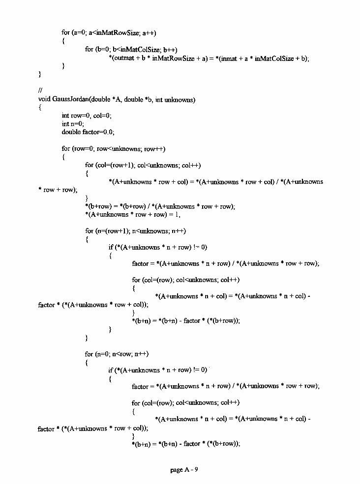
for (a=0; a<inMatRowSize; a++)
{for (b=0; b<inMatColSize; b++)
*(outmat + b *inMatRowSize + a)
= *(inmat + a* inMatColSize + b);
}
}
//
void GaussJordan(double *A, double *b, int unknowns)
{int row=0, col=0;
int n=0;
double factor=0.0;
for (row=0; row<unknowns; row++)
{for (col=(row+l); coKunknowns; col++)
{*(A+unknowns *
row + col)= *(A+unknowns *
row + col) / *(A+unknowns*row + row);
}
*(b+row) = *(b+row) / *(A+unknowns*row + row);
*(A+unknowns *row + row)
= 1;
for (n=(row+l); n<unknowns; n++)
{if (*(A+unknowns *
n + row)!= 0)
{factor = *(A+unknowns *
n + row) / *(A+unknowns*row + row);
for (col=(row); coKunknowns; col++)
{*(A+unknowns *
n + col)= *(A+unknowns *
n + col)-
factor * (*(A+unknowns *row + col));
}
*(b+n) = *(b+n) - factor * (*(b+row));
}
}
for (n=0; n<row; n++)
{if (*(A+unknowns
*n + row)
!= 0)
{factor = *(A+unknowns *
n + row) / *(A+unknowns*row + row);
for (col=(row); coKunknowns; col++)
{*(A+unknowns
*n + col)
= *(A+unknowns *n + col)
-
factor * (*(A+unknowns*row + col));
}
*(b+n) = *(b+n) - factor * (*(b+row));
page A - 9

Spline,h file:
#include <string.h>
#include <fstream.h>
#include <iomanip.h>
#include <afxwin.h>
#include "resource.h"
#include"matrix.h"
#include"constant.h"
IIIIIIIIIIIIIIIIIIIIIIIIIIIIIIIIIIIIIIIIIIIIIIIHIIIII
II spline.h
//
IIIIIIIIIIIIIIIIIIIIIIIIIIIIIIIIIIIHIIIIIIlllllllii
#imdef_SPLINE_H
#define
I*
***** *****
** Begin class definition calls. **
***** *****
*/
/*
Bsplines have 2 parameters: n & k;it must be supplied a knot vector with n+k+1 terms
and it must be given 3D polygon vertices numbering n+1 .
*/
//This comment should be disregarded by any programmer using this code.
// It is meant for Lodor,who wished that it be placed here. To all those who look
// for this, call me for a dot.
//Phi Delta Theta is a precious thing. Treasure it always, and good luck.
//153
//
//
//defines Basespline class
//
class Base_spline
page A - 10

{public:
void Setxi (int i, double Xi);double Getxi (int i) const;
BasesplineO;Base_spline(int init_n, int initk, int init_num_points);-BasesplineO;
protected:
//private data members
intn;
intk;int num_points;
int flag;double *knot;double (*N_Mat)[Max_N+2];
//private functions used internally to the classvirtual void CalcNMat 0;void CalcStep_N (int index, double tindex);double first (int i, double t);double formula (int i, int j, double (*Step_N)[2], doublet);
};
//
//defines Bspline class - inherited from Base_spline
//
class Bspline : public Basespline
{public:
BsplineO;Bspline(int initn, int initk, int inrt_num_points);Bspline(int initn, int initk, int inrtnumjpoints, double *init_knot);
-BsplineO;
double ReturnData(int Coord, int index);void SetPoly (int i, double *M);
doubleGetPoly (int i, int Coord) const;int getnO;
int getkO;
int getnumpointsO;
protected:
double (*Poly_Poirrts)[Num_Coordinates];
};
//
//defines OnlyGetNspline class -
used only for Airfoil curve fitting
//
page A - 1 1

class OnlyGetNspline: public Basespline
{public:
double GetNvalue(int nindex, int point);void CalcNnowO;
OnlyGetN_splineO;OnlyGetN_spline(int inftn, int initk, int init_num_points);OnlyGetN_spline(int initn, int initk, int inrt_num_points, double *init_knot);OnlyGetN_splineO;
};
//
//defines Airfoil class
//
class Airfoil
{public:
AirfoilO;Airfoil(int init_n, int initk, int init_num_points, double *init_knot, double zcoord, CString
location, BOOL method = TRUE);Airfoil(int initn, int initk, int inrtnumjpoints, double *init_knot, double zcoord, CString
location, double (*init_P), BOOL method= TRUE);
Airfoil(int initn, int init_k, int inft_num_points, double *init_knot, double zcoord, double
*polytop, double *polybot);
-AirfoilO;
double GetDataPoint(int Coord, int index, int toporbottom);voidWriteOutData(CString location);void SetName(CString name);
CString GetNameO const;
void SetPolygon(double *Values, int index, int toporbottom);double GetPolygon(int Coord, int index, int toporbottom);
private:
Bspline "topspline;
Bspline *botspline;
CString Name;double Z;
void Curvefit(double *data_top, double *data_bot, int initn, int initk, double *init_knot, int
toppoints, int botpoints, int toporbottom);
void Calculation(double *Ncurvefit, double *curvefitdata, int numofpoints, int
numofoolygons);
void SetPolyPoints(double *curvefitdata, double *data, int numofpoints, int numofpolygons,
int top_or_bottom);
void MixedCurvefit(double *data_top, double *data_bot, int initn, int initk, double
*init_knot, int toppoints, int botpoints, double *init_P, int toporbottom);
void SetMixedPolyPoints(double *init_P, double *curvefitdata, double *data, int
numofpoints, int numofpolygons, int top_or_bottom);
page A - 12

};
#endif//_SPLINE_H
Spline.cpp file:
^include"spline.h"
llllllllllllllllllllllllllllllllllllllllllllllllllll
II
II spline.cpp
//
// compiled July 15, 1999
// Matthew MacLean
// RIT master's thesis project
// Department ofMechanical Engineering//
// defines the class members and related functions for
// airfoil and spline classes
//
////////////////////////////////////////////////////
I*
***** *****
** Begin class function calls. **
***** *****
*/
//
//Basespline definitions
//
//general constructor - uses maximum values for inputs
Base_spline::Base_spline 0
{//initializes dynamic arrays for use.
knot = new double [Max_N +MaxK + 2];
N_Mat = new double [Max_Num_Points + l][Max_N + 2];
num_points=MaxNumPoints;
n =Max_N;k =Max_K;
}
//constructorwith specified bspline inputs
Basespline.Basespline (int initn, int initk, int init_num_points)
{//initializes dynamic arrays for use.
if(inrt_k>=2)
page A - 13

}
k = initk;else
k = 2;
if(imt_n>=(k-l))n = initn;
else
n = (k-l);if (init_num_points >= (n+1))
num_points = init_num_points;else
numjpoints= (n+1);
knot = new double [n + k + 2];N_Mat = new double [numjpoints + l][Max_N + 2];
//destructor returns dynamically allocated array memoryBasespline: -BasesplineO
{delete knot;delete
_ N_Mat;
}
//
double Base_spline::formula (int i, int j, double (*Step_N)[2], doublet)
{double Ret=0;double P1=0, P2=0;
if ((Step_N[i][l] != 0) && ((knot[i+j-l] - knot[i]) != 0))PI = ((t - knot[i])
*Step_N[i][l] / (knot[i+j-l]
- knot[i]));
else
P1=0;
if ((Step_N[i+l][l]!= 0) && ((knot[i+j] - knot[i+l])
!= 0))
P2 = ((knot[i+j] -t)*Step_N[i+l][l] / (knot[i+j]
- knot[i+l]));
else
P2 = 0;
Ret = Pl+P2;
retum(Ret);
}
//
double Basespline::first (int i, doublet)
{double Ret=0;
int c=0;
if ((t >= knot[i]) && (t < knot[i+l]))Ret= 1;
page A - 14

else
Ret = 0;
if ((t= knot[n+k+l]) && (knot[i]<knot[i+l]))
Ret=l;for (c=i+l; c<=(n+k+l); c++){
if(knot[c]!=knot[i+l]){
Ret=0;
break;
}
}
}
retumfRet);
}
//
void Base_spline::CalcN_Mat 0{
double dt = ((knot[n+k+l] - knot[l])/(numjpoints - 1));double tindex = knot[l];
intz=0;
for (z=l; z<=num_points; z++)
{if (z= num_points)
tindex = knot[n+k+l];
CalcStep_N(z, tindex);tindex = tindex + dt;
}
}
flag
//
void Base_spline::CalcStep_N (int index, double tindex)
{int i=0j=0;double (*Step_N) [2];
intz=0;int Nindex=0;
Step_N = new double [n+k+2][2];
for(j=l;j<=k;j++)
{for (i=l; K=(n+k+l-j); i++)
pageA- 15

}
if (j= 1)
Step_N[i][2] = first(i, tindex);else
Step_N[i][2] = formula(i, j, Step_N, tindex);
}
for (z=0; z <= (n+k+1); z++)Step_N[z][l] = Step_N[z][2];
for (Nindex=0; Nindex<=(n+1); Nindex++)N_Mat[index][Nindex] = Step_N[Nindex][l];
delete ? Step_N;
//
void Base_spline::Set_xi (int i, double Xi){
flag = 0;
if(Xi>=knot[i-l])knotfi] = Xi;
else
knot[i] = knot[i-l];}
//
double Base_spline::Get_xi (int i) const
{
retum(knot[i]);
}
//
//Bspline definitions
//
//general constructor -
uses maximum values for inputs
Bspline: .Bspline 0 : BasesplineO
{//initializes dynamic arrays for use.
PolyPoints = new double [MaxN + 2][Num_Coordinates];
}
//constructorwith specified bspline inputs
Bspline::Bspline (int initn, int initk, int inrtnumjpoints) : Basespline (initn, inftk,
inrt_num_points)
{//initializes dynamic arrays for use.
Poly_Points = new double [inrt_n + 2][Num_Coordinates];
}
page A - 16

//
Bspline: :Bspline (int initn, int initk, int inrt_num_points, double *init_knot) : Base_spline (init_n,
initk, init_num_points)
{int temp1=0;
//initializes dynamic arrays for use.
PolyPoints = new double [init_n + 2][Num_Coordinates];
}
for (temp1=1; templ<=(n+k+l); templ++)
knot[templ] = *(init_knot + tempi - 1);
//destructor returns dynamically allocated array memoryBspline: -BsplineO
{delete Q Poly_Points;
}
//
double Bspline: :RetumData(int Coord, int index)
{double Ret=0;
intz=0;
if (flag= 0)
CalcNJVlatO;
for(z=l;z<=(n+l);z++)
Ret = Ret + N_Mat[index][z]*Poly_Points[z][(Coord-l)];
return (Ret);
}
//
int Bspiine: :getn0
{
return(n);
}
//
int Bspline: :getk0
{
returnQc);
}
//
int Bspline: :getnumpointsO
{retum(num_points);
page A - 17

}
//
void Bspline: :Set_Poly (int i, double *M){
intz=0;
flag = 0;
for (z=0; z < Num_Coordinates; z++)Poly_Points[i][z] = *(M + z);
}
//
double Bspline: :Get_Poly (int i, int Coord) const
{
retum(Poly_Points[i][Coord- 1 ]);
}
//
//OnlyGetNspline definitions
//
void OnlyGetN_spline::CalcNnowO{
CalcNjMatO;
}
//
double OrdyGetN_spline::GetNvalue(int nindex, int point)
{
retum(N_Mat[point][nindex]);
}
//
OnlvGetN_spline::OnlyGetN_splineO : BasesplineO
{
}
//
OnlyGetN_spline::OnlyGetN_spline(int inftn, int initk, int inrt_num_points) : Basespline (initn,
initk, init_num_points)
{
}
//
OnlyGetN_spline::OnlyGetN_spline(int initn, int initk, int init_num_points, double *init_knot) :
Base_spline (initn, initk, init_num_points)
{int temp1=0;
page A- 18

for (templ=l; templ<=(n+k+l); templ++)knotftempl] = *(inrt_knot + tempi - 1);
CalcNnowO;}
//
OnlyGetNspline: :~OnlyGetN_splineO
{
}
//
//Airfoil definitions
//
Airfoil::AirfoilO
{topspline = new BsplineO;botspline = new BsplineO;Z = 0;
}
//
Airfoil: :Airfoil(int initn, int initk, int inrt_num_points, double *init_knot, double zcoord, CStringlocation, BOOL method)
{double (*topdata)[2];double (*botdata)[2];
inttop=0, bot=0;
ProvideCount(location, &top, &bot);
topdata = new double [top] [2];botdata = new double [bot][2];
GetData(location, topdata, botdata, top, bot);
topspline = new Bspline(init_n, initk, init_numjpoints, initknot);
botspline = new Bspline(init_n, initk, init_num_points, initknot);
if (method= TRUE)
{ //performs calculations by using matrix inversion method
Curvefit((&(topdata[0][0])), (&(botdata[0][0])), init_n, init_k, init_knot, top, bot, 1);
if (top !=bot)Curvefit((&(topdata[0][0])), (&(botdata[0][0])), init_n, rmt_k, init_knot, top,
bot, 2);
}
Z =
zcoord;
page A - 19

delete_ topdata;
delete Q botdata;}
//
Airfoil: :Airfoil(int initn, int initk, int initnumjoints, double *init_knot, double zcoord, double
*polytop, double *polybot)
{topspline = new Bspline(init_n, initk, init_num_points, initknot);botspline = new Bspline(init_n, initk, init_num_points, initknot);Z = 0;
int temp1=0;
for (temp1=1; tempK=(topspline->getnO + 1); templ++)
topsplme->Set_Poly(templ, (polytop + 2 * (tempi -1)));
for (templ=l; tempK=(botspline->getnO + 1); templ++)
botspline->Set_Poly(templ, (polybot + 2 * (tempi -1)));
}
//
Airfoil::Airfoil(int initn, int initk, int init_num_points, double *init_knot, double zcoord, CString
location, double (*init_P), BOOL method)
{double (*topdata)[2];double (*botdata)[2];int top=0, bot=0;
ProvideCount(location, &top, &bot);
topdata = new double [top] [2];botdata = new double [bot] [2];
GetData(location, topdata, botdata, top, bot);
topspline = new Bspline(init_n, initk, inrt_num_points, initknot);
botspline = new Bspline(init_n, initk, imt_num_points, initknot);
if(method= TRUE)
{ //performs calculations by using matnx inversion method
MixedCurvefit((&(topdata[0][0])), (&(botdata[0][0])), initn, initjc, init_knot, top,
bot, init_P, 1);
if (top !=bot)MixedCurvefit((&(topdata[0][0])), (&(botdata[0][0])), inft_n, initjc,
init_knot, top, bot, init_P, 2);
}
Z =
z_coord;
page A - 20

delete_ topdata;
delete_ botdata;
}
//
Airfoil: -AirfoilO
{delete topspline;
delete botspline;
}
//
void Airfoil::SetName(CString name){
Name = name;
}
//
CString AirfoiLGetNameO const
{return (Name);
}
//
void Airfoil::SetPolygon(double *Values, int index, int toporbottom)
{
switch(toporbottom)
{case 1:
topspline->Set_Poly(index, Values);
break;case 2:
botspline->Set_Poly(index, Values);
break;
default:
break;
}
}
//
double Airfoil: :GetPolygon(int Coord, int index, int toporbottom)
{double ret=0;
swrtch(toporbottom)
{case 1:
ret=(topspline->Get_Poly(index, Coord));
break;case 2:
ret=(botspline->Get_Poly(index, Coord));
page A -21

break;default:
break;
}
retum(ret);
}
//
void Airfoil: :WriteOutData(CString location)
{ofstream outfile(location);
int temp1=0;
for(templ=(topsplme->getnumpointsO); templ>=l; tempi)
{
outfile(topspline->RetumData(l, tempi));
outfile"\t";
outfile(topspline->RetumData(2, temp 1));
outfile"\n";
}
for(templ=l; templ<=(botspline->getnumpointsO); templ-H-)
{
ou1iUe<<(botsplme->RettirnData(l, tempi));
outfile"\t";
outfile(botspline->RetumData(2, tempi));
outfile"\n";
}
outfile.closeO;
}
//
double Airfoil: :GetDataPoint(int Coord, int index, int toporbottom)
{double ret=0;
switch(toporbottom)
{case 1:
ret= topspline->RetumData(Coord, index);
break;
case 2:
ret= botspline->RetumData(Coord, index);
break;
default:
break;
}
return (ret);
page A - 22

}
//
void Airfoil: :Curvefit(double *data_top, double *data_bot, int init_n, int rnrt_k, double *init_knot, inttoppoints, int botpoints, int toporbottom){
OnlyGetN_spline (*TempForN);double (*Ncurvefit);double (*curvefitdata);
int temp1=0, temp2=0;
switch (toporbottom){
case 1:
TempForN =new OnlyGetN_spline(init_n, initk, toppoints, imt_knot);
Ncurvefit = new double [toppoints *(initn+l)];
curvefitdata = new double [(initn+l)*toppoints];
for (temp 1=1; tempK=toppoints; templ++){
for (temp2=l; temp2<=(imt_n+l); temp2++)Ncurvefit[(templ - 1)
* (init_n + 1) + (temp2 - 1)]=
(TempForN->GetNvalue(temp2, tempi));
}
Calculation (Ncurvefit, curvefitdata, toppoints, (initn + 1));SetPolyPoints (curvefitdata, datatop, toppoints, (initn+l), 1);
if (toppoints= botpoints)SetPolyPoints (curvefitdata, databot, botpoints, (initn+l), 2);
break;case 2:
TempForN =new OnlyGetN_spline(init_n, initk, botpoints, initknot);
Ncurvefit = new double [(init_n+l)*botpoints];
curvefitdata = new double [(init_n+l)*botpoints];
for (templ=l; templ<=botpoints; templ-H-)
{for (temp2=l; temp2<=(rnit_n+l); temp2++)
Ncurvefit[(templ - 1)* (init_n + 1) + (temp2 - 1)] =
(TempForN->GetNvalue(temp2, tempi));
}
Calculation (Ncurvefit, curvefitdata, botpoints, (inftn + 1));
SetPolyPoints (curvefitdata, databot, botpoints, (initn + 1), 2);
break;
default:
break;
page A - 23

}
delete TempForN;delete Ncurvefit;delete curvefitdata;
}
//
void Airfoil: :Calculation(double *Ncurvefit, double *curvefitdata, int numofpoints, int
numofpolygons)
{double (*Ntrans);double (*curvestepl);double (*curvestep2);
curvestepl = new double [numofpolygons *numofpolygons]; IIn x n matrix
curvestep2 = new double [numofpolygons * numofpolygons]; IIn x n matrix
Ntrans = new double [numofpolygons * numofpoints]; IIn x p matnx
transpose(Ncurvefit, Ntrans, numofpoints, numofpolygons);
matmult(Ntrans, Ncurvefit, curvestepl, numofpolygons, numofpoints, numofpoints,
numofpolygons);
InvertMatrix(curvestepl, curvestep2, numofpolygons);
matmult (curvestep2, Ntrans, curvefitdata, numofpolygons, numofpolygons, numofpolygons,
numofpoints);
delete curvestep 1 ;
delete curvestep2;
delete Ntrans;
}
//
void Airfoil::MixedCurvefit(double *data_top, double *data_bot, int initn, int initk, double
?initknot, int toppoints, int botpoints, double *init_P, int toporbottom)
{OnlyGetN_spline (*TempForN);
double (*Ncurvefit);
double (*curvefitdata);
double (*calctopdata);
double (*calcbotdata);
int temp1=0, temp2=0;
calctopdata= new double [toppoints
*2];
calcbotdata= new double [botpoints
*2];
for (templ=0; templ<(toppoints*2); templ++)
*(calctopdata+templ)= *(data_top + tempi);
page A - 24

for (templ=0; templ<(botpoints *2); templ++)
*(calcbotdata+templ) = *(data_bot + tempi);
switch (toporbottom){
case 1:
TempForN =new OnlyGerN_spline(init_n, initk, toppoints, initknot);
Ncurvefit = new double [(init_n-l)*toppoints];
curvefitdata = new double [(init_n-l)*toppoints];
for (temp1=1; temp 1<=toppoints; temp 1++)
{for (temp2=l; temp2<=(imt_n+l); temp2++)
{if(temp2= l)
{*(calctopdata + 2 *
(temp 1-1))= *(data_top + 2 *
(templ-1)) - (*(init_P))*
(TempForN->GetNvalue(temp2, tempi));*(calctopdata + 2 *
(templ-1) + 1) = *(data_top + 2*
(templ-1) + 1) - (*(init_P + 1))*
(TempForN->GetNvalue(temp2, tempi));
}
if (temp2= (initn+l))
{?(calctopdata + 2 *
(templ-1)) = *(data_top + 2 *
(templ-1)) - (*(init_P + 2))*(TempForN->GetNvalue(temp2, tempi));
?(calctopdata + 2 *(templ-1) + 1) = *(data_top + 2
*(templ-1) + 1) - (*(init_P + 3))
*(TempForN->GetNvalue(temp2, tempi));
}
if ((temp2 !=1) && (temp2 != (init_n+l)))
Ncurvefit[(templ - 1)* (initjn - 1) + (temp2 - 2)] =
(TempForN->GetNvalue(temp2, tempi));
}
}
Calculation (Ncurvefit, curvefitdata, toppoints, (initn - 1));
SetMixedPolyPoints (init_P, curvefitdata, calctopdata, toppoints, (init_n-l),
D;
if (toppoints= botpoints)
{for (templ=l; templ<=botpoints; templ++)
{*(calcbotdata + 2 *
(templ-1))= *(data_bot + 2 *
(templ-1))- (*(inrt_P + 4))
* (TempForN->GetNvalue(l, tempi));
*(calcbotdata + 2 *(templ-1) + 1) = *(data_bot + 2 *
(templ-1) + 1) - (*(imt_P + 5))*(TempForN->GetNvalue(l, tempi));
*(calcbotdata + 2 *(templ-1)) = *(data_bot + 2 *
(templ-1))- (*(init_P + 6))
* (TempForN->GetNvalue((init_n+l), tempi));
page A - 25

?(calcbotdata + 2 *
(templ-1) + 1) = *(data_bot + 2*
(templ-1) + 1) - (*(init_P + 7))*
(TempForN->GetNvalue((imt_n+l), tempi));}
(init_n-l), 2);
SetMixedPolyPoints (initP, curvefitdata, calcbotdata, botpoints,
}
break;case 2:
TempForN =new OnlyGetN_spline(inrt_n, initk, botpoints, initknot);
Ncurvefit = new double [(initn-l)*botpoints];
curvefitdata = new double [(initn-l)*botpoints];
for (templ=l; templ<=botpoints; templ++)
{for (temp2=l; temp2<=(init_n+l); temp2++)
{if (temp2= 1)
{?(calcbotdata + 2 *
(templ-1)) = ?(data bot + 2 *
(templ-1)) - (*(init_P + 4))*
(TempForN->GetNvalue(temp2, tempi));?(calcbotdata + 2 ?
(templ-1) + 1)= ?(data_bot + 2
?(templ-1) + 1) - (?(init_P + 5))
?(TempForN->GetNvalue(temp2, tempi));
}
if (temp2= (initn+l))
{?(calcbotdata + 2 ?
(templ-1)) = ?(data_bot + 2 ?
(templ-1)) - (?(init_P + 6))?(Ten^)ForN->GetNvalue(temp2, tempi));
?(calcbotdata + 2 ?(templ-1) + 1) = ?(databot + 2
?(templ-1) + 1) - (?(init_P + 7))
?(TempForN->GetNvalue(temp2, tempi));
}
if ((temp2 != 1) && (temp2 != (init_n+l)))Ncurvefit[(templ - 1)
? (init_n - 1) + (temp2 - 2)]=
(TempForN->GetNvalue(temp2, tempi));
}
}
Calculation (Ncurvefit, curvefitdata, botpoints, (initn- 1));
SetMixedPolyPoints (initP, curvefitdata, calcbotdata, botpoints, (initn-l),
2);
break;
default:
}
delete TempForN;
break;
page A - 26

delete Ncurvefit;delete curvefitdata;
delete calctopdata;
delete calcbotdata;
}
//
void Airfoil::SetPolyPoints(double ?curvefitdata, double ?data, int numofpoints, int numofpolygons,int top_or_bottom)
{double (?output)[2];int temp1=0;
output=new double [numofpolygons] [2];
matmult(curvefitdata, data, (&(output[0][0])), numofpolygons, numofpoints, numofpoints, 2);
switch (toporbottom)
{case 1:
for (templ=l; templ<=numofpolygons; templ++)
topspline->Set_Poly(templ, (&(output[temp 1 - 1][0])));
break;case 2:
for (templ=l; templ<=numofpolygons; templ++)
botspline->Set_Poly(templ, (&(output[temp 1 - 1][0])));
break;
default:
break;
}
}
delete fj output;
//
void Airfoil: :SetMixedPolyPoints(double ?initP, double ?curvefitdata, double ?data, int
numofpoints, int numofpolygons, int toporbottom)
{double (*output)[2];
int temp1=0;
output= new double [numofpolygons] [2];
matmult(curvefitdata, data, (&(output[0][0])), numofpolygons, numofpoints, numofpoints, 2);
switch (toporbottom)
{case 1:
topspline->Set_Poly(l, initP);
topspline->Set_Poly(numofpolygcHis+2, (inkJP+2));
for (templ=l; templ<=nurnofpolygons; templ++)
page A - 27

topspline->Set_Poly(templ+l, (&(output[templ - 1][0])));
break;case 2:
botspline->Set_Poly(l, (init_P+4));
botspline->Set_Poly(numofpolygons+2, (init_P+6));for (temp1=1; templ<=numofpolygons; templ++)
botspline->Set_Poly(templ+l, (&(output[temp 1 - 1][0])));
break;default:
break;
}
delete_ output;
Resource.h file:
II { {NO_DEPENDENCIES } }//Microsoft Developer Studio generated include file.
// Used by Spline. re
//
#define IDM FOUR 100
#define IDIJCON1 101
#define IDM_EXIT 110
#define IDD_TERMS 200
#define IDD_TrrLE 201
#define IDM_ABOUT 300
#define IDC_EDIT0 1000
#define IDC_EDIT1 1001
#define IDC_EDIT2 1002
#define IDC_EDIT3 1003
#define IDC_EDIT4 1004
#define IDC_EDIT5 1005
#define IDC_EDIT6 1006
#define IDC_EDIT7 1007
^define IDC_EDjT8 1008
#define IDC_EDIT9 1009
#define IDC_EDIT10 1010
#defineIDC_EDITll 1011
#define IDC_EDIT12 1012
#define IDC_EDIT13 1013
#define IDC_EDIT14 1014
#define IDC_EDIT15 1015
#define IDC_EDIT16 1016
#define IDC_EDIT17 1017
#define IDC_EDIT1 8 1018
#define IDC_EDIT19 1019
#define IDC_EDIT20 1020
#defineIDC EDIT21 1021
page A - 28

#define IDC_EDIT22 1022
#defineIDC EDIT23 1023
#defineH)C EDJT24 1024
#define IDC_EDIT25 1025
#define IDC_EDIT26 1026
#defineIDC EDIT27 1027
#defineIDC EDIT28 1028
#define IDC_EDIT29 1029
#defineIDC EDIT30 1030
#defineIDC_EDiT31 1031
#define IDC_EDIT32 1032
#defineIDC EDIT33 1033
#define IDC_EDIT34 1034
#define IDC_EDIT35 1035
#define IDC_EDIT36 1036
#defineIDC EDIT37 1037
#defineIDC EDIT38 1038
#define IDC_EDIT39 1039
#defineIDC EDIT40 1040
#defineIDC_EDIT41 1041
#define IDC_EDIT42 1042
#defineIDC RADI01 2000
#defineIDC RADI02 2005
#defineIDC RADI03 2010
#define IDMEXPORT 40001
#define IDM NEW 40002
#define IDM KNOT 40003
#defineIDM POLYGON1 40004
fldefine EDM POLYGON2 40005
#defineIDM CONSTS 40006
#defineIDM SCALE 40007
#defineIDM MATLAB 40008
#defineIDM AERODYN 40009
#define IDM XFOIL 40010
#defineIDM ERRORCALC 40011
#defineIDM CURJNFO 40012
MefinelDM RETRIEVE 40013
#define IDM VERTEX 40014
// Next default values for new objects
//
#ifdefAPSTUDIO_INVOKED
#ifiidefAPSTUDIO_READONLY_SYMBOLS
#define 1 10
#define 40015
#define_APS_NEXT_CONTROL_VALUE 1020
#define_APS_NEXT_SYMED_VALUE 101
flendif
#endif
page A - 29

Spline, re file:
//Microsoft Developer Studio generated resource script
//
#include"resource.h"
#define APSTUDIO_READONLY_SYMBOLS
/////////////////////////////////////////////////////////////////////////////
//
// Generated from the TEXTINCLUDE 2 resource.
//
tfdefine APSTUDIO_HIDDEN_SYMBOLS
#include "windows
#undefAPSTUDIO_HIDDEN_SYMBOLS
^include"afxres.h"
lllllllllllllllllllllllllllllllllllllllllllllllllllllllllllllllllllllllllllll
#undefAPSTUDIO_READONLY_SYMBOLS
lllllllllllllllllllllllllllllllllllllllllllllllllllllllllllllllllllllllllllll
II English (U.S.) resources
#if !defined(AFX_RESOURCE_DLL) || defined(AFX_TARG_ENU)#ifdef_WIN32
LANGUAGE LANG_ENGLISH, SUBLANG_ENGLISH_US
#pragma code_page(1252)
#endif//_WIN32
IIIIIIIIIIIIIIIIIIIIIIIIIIIIIIIIIIIIIIIIIIIIIIIIIIIIIIIIIIIIIIIIIIIIIIIIHIII
II
IIMenu
//
AIRFOILMENUMENU DISCARDABLE
BEGIN
POPUP"File"
BEGIN
MENUTTEM "New. . . ", IDM_NEW
MENUrTEM "Plot Scale...", IDM_SCALE
MENUTTEM "Export Data...", IDM_EXPORT
MENUTTEM "Export Vertices...", IDMJVERTEX
MENUTTEM "Exit", E>M_EXIT
END
POPUP"Data"
BEGIN
MENUTTEM "Knot...", IDM_KNOT
MENUTTEM "Top Polygon...",EDM_POLYGON1
MENUTTEM "Bottom Polygon. . . ", IDM_POLYGON2
END
POPUP"Calculations"
page A - 30

BEGIN
MENUTTEM "Current Airfoil Information...", IDM CURINFOMENUITEM "Set Aerodynamic Parameters...'", IDM AERODYNMENUITEM "Call X-FOIL", IDM_XFOILMENUITEM "Retrieve LastXFOIL CaU...", IDM RETRIEVE
END
POPUP"Help"
BEGIN
MENUITEM "About...", IDM ABOUTEND
END
IIIIIIIIIIIIIIIIIIIIIIIIIIIIIIIIIIIIIIIIIIIIIIIIIIIIIIIIIIIIIIIIIIIIIIIIIHIIII
II Dialog//
ABOUTBOX DIALOG DISCARDABLE 14, 22, 200, 77STYLE DS_MODALFRAME | WS POPUP | WS_CAPTION
CAPTION"About"
FONT 8, "MS SansSerif'
BEGIN
CTEXT "Airfoil Spline Program",-l,28,5, 144,8CTEXT "RIT - Master's Thesis",-l,28,15,144,8
CTEXT "ByMatthew MacLean",-l,28,26,144,8
CTEXT "version 3.0",201,59,37,83,8
DEFPUSHBUTTON "OK",IDOK,84,55,32, 14,WS_GROUP
END
CONSTANTS DIALOG DISCARDABLE 0, 0, 187, 109
STYLE DS_MODALFRAME | WS_POPUP | WS_CAPTION | WS_SYSMENU
CAPTION "GlobalConstants"
FONT 8, "MS Sans Serif
BEGIN
LTEXT "Polygon Points (n):",IDC_STATIC, 1 8, 14,75,8
LTEXT "Order (k):",IDC_STATIC,46,34,29,8
LTEXT "Data Points:",IDC_STATIC,38,54,55,8
EDTTTEXT IDC_EDIT1,104,14,40,14,ES_AUTOHSCROLL
EDITTEXT IDC_EDIT2,104,34,40,14,ES_AUTOHSCROLL
EDTTTEXT IDC_EDIT3,104,54,40, 14,ES_AUTOHSCROLL
DEFPUSHBUTTON "OK",IDOK,23,88,50, 14
PUSHBUTTON "Cancel",IDCANCEL,103,88,50, 14
END
NEWAIRFOIL DIALOG DISCARDABLE 0, 0, 187, 98
STYLE DS_MODALFRAME | WS_POPUP | WS_CAPTION | WS_SYSMENU
CAPTION "NewAirfoil"
FONT 8, "MS SansSerif'
BEGIN
DEFPUSHBUTTON "OK",IDOK,26,77,50, 14
page A - 3 1

PUSHBUTTON "Cancel",IDCANCEL, 101,77,50,14CONTROL "Import from File",IDC_RADI01,"Button",
BS_AUTORADIOBUTTON |WS_GROUP,55,15,62,10
CONTROL "Input Polygon Poirrts",IDC_RADI02,"Button'',BS_AUTORADIOBUTTON,55,33,77,10
CONTROL "Specify End Points",IDC_RADI03,"Button",BS_AUTORADIOBUTTON,55,51,76, 10
END
POLYGON DIALOG DISCARDABLE 0, 0, 249, 163STYLE DS_MODALFRAME | WS_POPUP | WS_CAPTION | WS_SYSMENU
CAPTION "PolygonPoints"
FONT 8, "MS Sans Serif
BEGIN
LTEXT "x",IDC_STATIC,46,5,8,8
LTEXT "y",IDC_STATIC,94,5,8,8
LTEXT "x",IDC_STATIC,164,5,8,8
LTEXT "y",IDC_STATIC,212,5,8,8
EDITTEXT IDC_EDIT1,30,
17,40, 14,ES_AUTOHSCROLLEDITTEXT IDC_EDIT2,75, 17,40,14,ES_AUTOHSCROLLEDTTTEXT IDC_EDIT5,30,36,40,14,ES_AUTOHSCROLL
EDTTTEXT IDC_EDIT6,75,36,40,14,ES_AUTOHSCROLL
EDTTTEXT IDC_EDIT10,30,55,40, 14,ES_AUTOHSCROLL
EDTTTEXT IDC_EDIT8,75,55,40,14,ES_AUTOHSCROLL
EDITTEXT IDC_EDIT9,30,74,40,14,ES_AUTOHSCROLL
EDITTEXT IDC_EDIT11,75,74,40,14,ES_AUTOHSCROLL
EDITTEXT IDC_EDIT16,30,93,40, 14,ES_AUTOHSCROLL
EDTTTEXT IDC_EDIT14,75,93,40,14,ES_AUTOHSCROLL
EDITTEXT IDC_EDIT15,30, 1 12,40, 14,ES_AUTOHSCROLL
EDITTEXT IDC_EDIT17,75, 1 12,40,14,ES_AUTOHSCROLL
EDTTTEXT IDC_EDIT13,145,18,40,14,ES_AUTOHSCROLL
EDTTTEXT IDC_EDTT1 8, 190, 18,40, 14,ES_AUTOHSCROLL
EDITTEXT IDC_EDIT3, 145,37,40, 14,ES_AUTOHSCROLL
EDTTTEXT IDC_EDIT4,190,37,40,14,ES_AUTOHSCROLL
LTEXT "#1",IDC_STATIC,16,19,9,8
LTEXT "#2",IDC_STATIC, 16,38,9,8
LTEXT "#3",IDC_STATIC,16,57,9,8
LTEXT "#4",IDC_STATIC,16,76,9,8
LTEXT "#5",IDC_STATIC, 15,95,9,8
LTEXT "#6",IDC_STATIC,16,114,9,8
LTEXT "#7",IDC_STATIC,125,20,9,8
LTEXT "#8",IDC_STATIC, 125,39,9,8
DEFPUSHBUTTON "OK",JT>OK,54,142,50,14
PUSHBUTTON "Cancel",IDCANCEL, 155, 142,50, 14
EDITTEXT IDC_EDrr7,145,56,40,14,ES_AUTOHSCROLL
EDITTEXT IDC_EDIT12,190,56,40,14,ES_AUTOHSCROLL
LTEXT "#9",IDC_STA,nC,125,58,9,8
EDnTEXT IDC_EDrri9,145,75,40,14,ES_AUTOHSCROLL
EDITTEXT IDC_EDIT20, 190,75,40, 14,ES_AUTOHSCROLL
LTEXT "#10",IDC_STATIC,125,77,18,8
EDTTTEXT IDC EDIT21,145,94,40,14,ES_AUTOHSCROLL
page A - 32

EDITTEXT
LTEXT
EDITTEXT
EDITTEXT
LTEXT
END
roC_EDIT22,190,94,40,14,ES_AUTOHSCROLL"#1 1",IDC_STATIC,125,96,18,8
IDC_EDIT23,145,113,40,14,ES_AUTOHSCROLLH>C_EDIT24, 190, 1 13,40, 14,ES_AUTOHSCROLL
"#12",TDC_STATIC,125,1 15,18,8
KNOT DIALOG DISCARDABLE 0, 0, 288, 108STYLE DS_MODALFRAME | WS_POPUP|WS CAPTION IWS SYSMENUCAPTION "Knot
Vector"
FONT 8, "MS Sans Serif
BEGIN
EDITTEXT IDC_EDTT0,9, 14,27, 14,ES_AUTOHSCROLLEDITTEXT IDC_EDIT1,44, 14,27, 14,ES_AUTOHSCROLLEDITTEXT IDC_EDIT2,79,14,27, 14,ES_AUTOHSCROLLEDITTEXT IDC_EDIT3, 1 14, 14,27,14,ES_AUTOHSCROLLEDITTEXT IDC_EDIT4,149, 14,27, 14,ES_AUTOHSCROLLEDTTTEXT IDC_EDIT5, 184,14,27,14,ES_AUTOHSCROLLEDTTTEXT IDC_EDIT6,2 19, 14,27, 14,ES_AUTOHSCROLLEDITTEXT IDC_EDIT7,254,14,27,14,ES_AUTOHSCROLLEDITTEXT IDC_EDIT8,9,37,27, 14,ES_AUTOHSCROLLEDITTEXT IDC_EDIT9,44,37,27,14,ES_AUTOHSCROLLEDITTEXT IDC_EDIT10,79,37,27,14,ES_AUTOHSCROLLEDITTEXT IDC_EDIT1 1,1 14,37,27, 14,ES_AUTOHSCROLLEDITTEXT IDC_EDIT12,149,37,27,14,ES_AUTOHSCROLLEDITTEXT IDC_EDIT13,184,37,27,14,ES_AUTOHSCROLL
EDITTEXT IDC_EDIT14,219,37,27,14,ES_AUTOHSCROLLEDTTTEXT IDC_EDIT15,254,37,27,14,ES_AUTOHSCROLL
DEFPUSHBUTTON "OK",IDOK,78,87,50,14
PUSHBUTTON "Cancel",IDCANCEL,160,87,50,14
EDITTEXT IDC_EDIT16,9,60,27,14,ES_AUTOHSCROLL
EDITTEXT IDC_EDIT 17,44,60,27, 14,ES_AUTOHSCROLL
EDTTTEXT IDC_EDIT18,79,60,27, 14,ES_AUTOHSCROLL
EDITTEXT IDC_EDIT19,1 14,60,27,14,ES_AUTOHSCROLL
EDITTEXT IDC_EDIT20, 149,60,27, 14,ES_AUTOHSCROLL
EDTTTEXT TDC_EDIT2 1, 184,60,27,14,ES_AUTOHSCROLL
EDTTTEXT IDC_EDIT22,219,60,27,14,ES_AUTOHSCROLL
EDTTTEXT IDC_EDIT23,254,60,27, 14,ES_AUTOHSCROLL
END
SCALEBOX DIALOG DISCARDABLE 0, 0, 187, 64
STYLE DS_MODALFRAME | WS_POPUP | WS_CAPTION | WS_SYSMENU
CAPTION "PlottingScale"
FONT 8, "MS Sans Serif
BEGIN
LTEXT "Y/X scale factor:",IDC_STATIC,33,17,50,8
EDTTTEXT IDC_EDIT1,101,15,40,14,ES_AUTOHSCROLL
DEFPUSHBUTTON "OK",IDOK,21,43,50,14
PUSHBUTTON "Cancel",IDCANCEL,104,43,50,14
END
page A - 33

AEROPARAMETER DIALOG DISCARDABLE 0, 0 266 149
STYLE DS_MODALFRAME | WS_POPUP | WS_CAPTi6n | WS_SYSMENU
CAPTION "Aerodynamic Parameters"
FONT 8, "MS Sans Serif
BEGIN
DEFPUSHBUTTON "OK",IDOK,51,128,50 14
PUSHBUTTON "Cancel",IDCANCEL,142,128,50,14LTEXT "Angle ofAttack:",IDC_STATIC,25,20,52,8LTEXT "Reynold's Number:",IDC_STATIC,25,58,60,8LTEXT "MachNumber:",IDC_STATIC,25,99,48 8
EDTTTEXT IDC_EDm,121,18,95,14,ES_AUTOHSCROLLEDTTTEXT IDC_EDIT2,121,56,95,14,ES_AUTOHSCROLLEDTTTEXT IDC_EDIT3,121,97,95,14,ES_AUTOHSCROLL
END
ENDPT DIALOG DISCARDABLE 0, 0, 241, 207STYLE DS_MODALFRAME | WS_POPUP | WS_CAPTION | WS_SYSMENU
CAPTION "Specified PolygonPoints"
FONT 8, "MS Sans Serif
BEGIN
DEFPUSHBUTTON "OK",IDOK,4 1,186,50,14
PUSHBUTTON "Cancel",IDCANCEL,149, 186,50, 14GROUPBOX "Top Spline",IDC_STATIC,36,15,169,74
GROUPBOX "Bottom Spline",IDC_STATIC,36,92,169,74
EDITTEXT IDC_EDIT1,101,32,40,14,ES CENTER | ES_AUTOHSCROLL
EDITTEXT IDC_EDIT2, 155,32,40, 14,ES_CENTER | ES_AUTOHSCROLL
EDITTEXT IDC_EDIT3,101,60,40,14,ES_CENTER | ES_AUTOHSCROLL
EDITTEXT IDC_EDIT4, 155,60,40,14,ES_CENTER | ES_AUTOHSCROLL
EDTTTEXT H>C_EDIT5,101,1 12,40,14,ES_CENTER | ES_AUTOHSCROLL
EDTTTEXT IDC_EDIT6, 155, 1 12,40,14,ES_CENTER | ES_AUTOHSCROLL
EDITTEXT IDC_EDIT7,101,141,40,14,ES_CENTER | ES_AUTOHSCROLL
EDTTTEXT IDC_EDIT8,155,141,40,14,ES_CENTER | ES_AUTOHSCROLL
LTEXT "First Point:",IDC_STATIC,41,34,34,8
LTEXT "Last Point:",IDC_STATIC,41,63,34,8
LTEXT "First Point:",IDC_STATIC,46,118,34,8
LTEXT "Last Point:",IDC_STATIC,46, 147,34,8
END
#ifdefAPSTUDIO_INVOKED
lllllllllllllllllllllllllllllllllllllllllllllllllllllllllllllllllllllllllllll
II
II TEXTINCLUDE
//
1 TEXTINCLUDE DISCARDABLE
BEGIN"resource.h\0"
END
2 TEXTINCLUDE DISCARDABLE
BEGIN
page A - 34

"#define APSTUDIO_HIDDEN_SYMBOLSV\n"
"#include""windows.h""V\n"
"#undefAPSTUDIOJUDDEN SYMBOLS\r\n"
"#include""afxres.h""\r\n"
END
3 TEXTINCLUDE DISCARDABLE
BEGIN"\r\n"
"\0"
END
#endif //APSTUDIO INVOKED
lllllllllllllllllllllllllllllllllllllllllllllllllllllllllllllllllllllllllllll
II
II Icon
//
// Icon with lowest ID value placed first to ensure application icon
// remains consistent on all systems.
IDIJCON1 ICON DISCARDABLE"iconl.ico"
lllllllllllllllllllllllllllllllllllllllllllllllllllllllllllllllllllllllllllll
II
II DESIGNINFO
//
#ifdefAPSTUDIOJNVOKED
GUIDELINES DESIGNINFO DISCARDABLE
BEGIN
"CONSTANTS", DIALOG
BEGIN
LEFTMARGIN, 7
RIGHTMARGTN, 180
TOPMARGIN, 7
BOTTOMMARGIN, 102
END
"NEWAIRFOIL", DIALOG
BEGIN
LEFTMARGIN, 7
RIGHTMARGIN, 180
TOPMARGIN, 7
BOTTOMMARGIN, 91
END
"POLYGON", DIALOG
BEGIN
LEFTMARGIN, 7
page A - 35

RIGHTMARGIN, 242
TOPMARGIN, 5
BOTTOMMARGIN, 156END
"KNOT", DIALOGBEGIN
LEFTMARGIN, 9
RIGHTMARGIN, 281
BOTTOMMARGIN, 101END
"SCALEBOX", DIALOGBEGIN
LEFTMARGIN, 7
RIGHTMARGIN, 180
TOPMARGIN, 7
BOTTOMMARGIN, 57END
"AEROPARAMETER", DIALOGBEGIN
LEFTMARGIN, 7
RIGHTMARGIN, 259
TOPMARGIN, 7
BOTTOMMARGIN, 142END
"ENDPT", DIALOG
BEGIN
LEFTMARGIN, 7
RIGHTMARGIN, 234
TOPMARGIN, 7
BOTTOMMARGIN, 200
END
END
#endif // APSTUDKMNVOKED
#endif // English (US.) resources
lllllllllllllllllllllllllllllllllllllllllllllllllllllllllllllllllllllllllllll
#ifhdefAPSTUDKMNVOKED
lllllllllllllllllllllllllllllllllllllllllllllllllllllllllllllllllllllllllllll
II
II Generated from the TEXTINCLUDE 3 resource.
//
lllllllllllllllllllllllllllllllllllllllllllllllllllllllllllllllllllllllllllll
page A - 36

#endif // not APSTUDIO INVOKED
WinDig.h file:
#include <string.h>
#include <iomanip.h>
#include <afxwin.h>
#include <afxcmn.h>
#include <afxdlgs.h>
#include <math.h>
^include "resource.h"
#include"constant.h"
#include"matrix.h"
#include"spline.h"
IIIIIIIIIIIIIIIIIIIIIIIIIIIIIIIIIIIIIIIIIIIIIIIIIIHII
II WinDlg.h
//
IIIIIIIIIIIIIIIIIIIIIIIIIIIIIIIIHIIHIIIHIIIIIIIll
#ifodef_WinDlg_H
#define
extern CString mytitle;extern int radio;
extern int method;
extern int mcxClient;
extern int m_cyChent;
extern int globalflag;
extern double scalefactor;
extern CString globalimport;extern CString globalexport;extern CString globalCurDir;
extern Airfoil *currentairfoil;extern double globalknot[Max_N +MaxK +1];
extern int globalN;
extern int globalK;
extern int globalDataP;
extern double alpha;
extern double reynolds;
extern double machnum;
extern float cl;
page A - 37

extern float cdrag;
extern float cm;
//XY Scale Dialog Boxclass CScaleDataDialog : public CDialog
public:
CScaleDataDialog(CWnd*pParentWnd=NULL) : CDialog("Scalebox",pParentWnd)
}
virtual void DoDataExchange(CDataExchange^pDX);
//Constants Dialog Box
class CConstDataDialog : public CDialog{public:
CConstDataDialog(CWnd+pParentWnd=NULL) : CDialog("Constarxts",pParentWnd)
{
}
virtual void DoDataExchange(CDataExchange+ pDX)
};
//Knot Vector Box
class CKnotDataDialog : public CDialog{public:
CKnotDataDialog(CWnd+pParentWnd=NULL) : CDialog("Knot",pParentWnd)
{
}
virtual voidDoDataExchange(CDataExchange+
pDX);
};
//New Airfoil Dialog Box
class CNewDataDialog : public CDialog
{public:
CNewDataDialog(CWnd+pParentWnd=NULL) : CDialog("NewAirfoil",pParentWnd)
{
}
virtual voidDoDataExchange(CDataExchange+
pDX);
};
//specified polygons points dialog box
class CEndPtDialog . public CDialog
{
page A - 38

public:
CEndPtDialog(CWnd+pParentWnd=NULL);
virtual void DoDataExchange(CDataExchange* pDX);
virtual double ?RetumPolyPtO;
private:
double PolyPt [4] [2];
};
//Top Bspline Polygon Box
class CTopSpiineDataDialog : public CDialog
{public:
CTopSplineDataDialog(CWnd+pParentWnd=NULL) : CDialog("Polygon",pParentWnd)
{
}
virtual voidDoDataExchange(CDataExchange^
pDX);
};
//Bottom Bspline Polygon Box
class CBotSplineDataDialog : public CDialog
{public:
CBotSplineDataDialog(CWnd+pParentWnd=NULL) : CDialog("Polygon",pParentWnd)
{
}
virtual voidDoDataExchange(CDataExchange^
pDX);
};
// Bspline Polygon Box for a new airfoil
class CNewSplineDataDialog : public CDialog
{public:
CNewSplineDataDialog(intN,CWnd+
PParentWnd=NULL) :
CDialog("Polygon",pParentWnd)
{Values = new double [N][2];
int i=0;
for (i=0; i<N; i++)
{Values[i][0]
= 0.0;
Values[i][l]= 0.0;
}
}
-CNewSplineDataDialogO
{delete Q Values;
page A - 39

}
virtual double *RetumAddressO;virtual void DoDataExchange(CDataExchange+
pDX);private:
double (?Values)^];};
//Aerodynamic Parameters Dialog Boxclass CAeroDataDialog : public CDialog
public:
CAeroDataDialog(CWnd+pParentWnd=NULL) : CDialog("AeroParameter",pParentWnd)
}
virtual void DoDataExchange(CDataExchange+pDX);
#endif//_WinDlg_H
WinDlg.cpp file:
#include"WinDlg.h"
llllllllllllllllllllllllllllllllllllllllllllllllllll
II
IIWinDlg.cpp//
// compiled July 15, 1999
//Matthew MacLean
// RIT master's thesis project
// Department ofMechanical Engineering//
// defines the various dialog box members in support
// of theWinFunc.cpp file
//
llllllllllllllllllllllllllllllllllllllllllllllllllll
II
voidCScaleDataDialog::DoDataExchange(CDataExchange*
pDX)
{CDialog: :DoDataExchange(pDX);
DDX_Text(pDX, IDC_EDIT1, scalefactor);
}
//
voidCNewDataDialog::DoDataExchange(CDataExchange^
pDX)
page A - 40

CDialog: :DoDataExchange(pDX);
DDXRadioijpDX, EDC_RADI01, radio);
//
voidCConstDataDialog::DoDataExchange(CDataExchange+
pDX)
{CDialog: :DoDataExchange(pDX);
DDX_Text(pDX, EDC_EDIT1, globalN);
DDX_Text(pDX, IDC_EDTT2, globalK);
DDX_Text(pDX, IDC_EDIT3, globalDataP);
DDX_Radio(pDX, IDC_RADI01, method);
//
CEndPtDialog::CEndPtDialog(CWnd+pParentWnd) : CDialog("Endpt",pParentWnd)
{
PolyPt[0][0]= 0
PolyPt[0][l] = 0
PolyPt[l][0] = 1
PolyPt[l][l] = 0
PolyPt[2][0]= 0
PolyPt[2][l] = 0
PolyPt[3][0]= 1
PolyPt[3][l]= 0
//
voidCEndPtDialog::DoDataExchange(CDataExchange+
pDX)
{CDialog: :DoDataExchange(pDX);
DDX_Text(pDX, IDC_EDIT1, PolyPt[0][0])
DDX_Text(pDX, EDC_EDIT2, PolyPt[0][l])
DDX_Text(pDX, EDC_EDIT3, PolyPt[l][0])
DDX_Text(pDX, TDC_EDIT4, PolyPt[l][l])
DDX_Text(pDX, IDC_EDIT5, PolyPt[2][0])
DDX_Text(pDX, IDC_EDIT6, PolyPt[2][l]>
DDX_Text(pDX, EDC_EDIT7, PolyPt[3][0])
DDX_Text(pDX EDC_EDIT8, PolyPt[3][l])
//
double *CEndPtDialog::ReturnPolyPtO
{return (&PolyPt[0][0]);
}
page A -41

//
double ?CNewSplineDataDialog: :ReturnAddressO
{
return(&Values[0][0]);
}
//
void CNewSplineDataDialog: :DoDataExchange(CDataExchange+ pDX)
{CDialog: :DoDataExchange(pDX);
DDX_Text(pDX, EDC_EDIT1, Values[0][0]);
DDX_Text(pDX, IDC_EDIT2, Values[0][l]);
DDX_Text(pDX, DDC_EDIT5, Values[l][0]);
DDX_Text(pDX, EDC_EDIT6, Values[l][l]);
if(globalN>=2)
DDX_Text(pDX, IDC_EDIT10, Values[2][0]);
DDX_Text(pDX, IDC_EDIT8, Values[2][l]);
f(globalN>=3)
DDX_Text(pDX, IDC_EDIT9, Values[3][0]);
DDX_Text(pDX IDC_EDIT11, Values[3][l]);
f(globalN>=4)
DDX_Text(pDX, IDC_EDIT16, Values[4][0]);
DDX_Text(pDX, IDC_EDIT14, Values[4][l]);
f(globalN>=5)
DDX_Text(pDX, EDC_EDm5, Values[5][0]);
DDX_Text(pDX EDC_EDIT17, Values[5][l]);
f(_lobalN>=6)
DDX_Text(pDX IDC_EDm3, Values[6][0]);
DDX_Text(pDX IDC_EDIT18, Values[6][l]);
f(globalN>=7)
DDX_Text(pDX, IDC_EDIT3, Values[7][0]);
page A - 42

if(globalN>=8)
f(globalN>=9)
DDX_Text(pDX, IDC_EDIT4, Values[7][l]);
DDX_Text(pDX, IDC_EDIT7, Values[8][0]);DDX_Text(pDX, IDC_EDIT12, Values[8] [1]);
DDX_Text(pDX, IDC_EDm9, Values[9][0]);DDX_Text(pDX, IDC_EDIT20, Values[9][l]);
f(globalN>=10)
DDX_Text(pDX, IDC_EDIT21, Values[10][0]);
DDX_Text(pDX, IDC_EDIT22, Values[10][1]);
f(globalN>=ll)
DDX_Text(pDX, IDC_EDIT23, Values[10][0]);
DDX_Text(pDX, IDC_EDIT24, Values[10][1]);
}
//
voidCTopSplineDataDialog::DoDataExchange(CDataExchange+
pDX)
{CDialog: :DoDataExchange(pDX);
double tempvalue[2];
if(globalflag= 1)
{
tempvalue[0]=currentairfoil->GetPolygon(l, 1,1);
tempvalue[l]=
currentairfoil->GetPolygon(2, 1, 1);
DDXJTexttpDX, IDC_EDIT1, tempvalue[0]);
DDXJTexttpDX, IDC_EDIT2, tempvalue[l]);
currentairfoil->SetPolygon(tempvalue, 1, 1);
tempvalue[0]=currentairfoil->GetPolygon(l, 2, 1);
tempvaluefl]=
currentairfoil->GetPolygon(2, 2, 1);
DDX_Text(pDX, IDC_EDTT5, tempvalue[0]);
DDX_Text(pDX, IDC_EDIT6, tempvalue[l]);
curTentairfoil->SetPolygon(tempvalue, 2, 1);
if(globalN>=2)
{
tempvalue[0]=currentairfoil->GetPolygon(l, 3, 1);
page A - 43

}
tempvaluefl]=
currentairfoil->GetPolygon(2, 3, 1);DDX_Text(pDX EDC_EDIT10, tempvalue[0]);DDXJTexttpDX, IDC_EDIT8, tempvalue[l]);cuirerrtairfoil->SetPolygon(tempvalue, 3, 1);
if(globalN>=3){
tempvalue[0]=
airrentairfoil->GetPolygon(l, 4, 1);
tempvalue[l]=
currentairfoil->GetPolygon(2, 4, 1);
DDXJTexttpDX IDC_EDiT9, tempvalue[0]);DDXJTexttpDX, EDC_EDITll,tempvalue[l]);cuiTenlairfoil->SetPolygon(ternpvalue, 4, 1);
}
if(globalN>=4)
{
tempvalue[0]=
currentairfoil->GetPolygon(l, 5, 1);
tempvaluefl]=
currentairfoil->GetPolygon(2, 5, 1);
DDXJTexttpDX IDC_EDIT16, tempvalue[0]);
DDXJTexttpDX, EDC_EDIT14, tempvalue[l]);
cuiTentairfoil->SetPolygon(tenpvalue, 5, 1);
}
if(globalN>=5)
{
tempvalue[0]=
currerjtairfoil->GetPolygon(l, 6, 1);
tempvalue[l]=
currentairfoil->GetPolygon(2, 6, 1);
DDXJTexttpDX, E>C_EDIT15, tempvalue[0]);
DDXJTexttpDX, EDC_EDIT17, tempvaluefl]);
curTentairfoil->SetPolygon(ternpvalue, 6, 1);
}
if(globalN>=6)
{
tempvalue[0]=
currentairfoil->GetPolygon(l, 7, 1);
tempvalue[l]=
currerjtairfoil->GetPolygon(2, 7, 1);
DDXTexttpDX, IDC EDTT13, tempvalue[0]);
DDXJTexttpDX EDC_EDrri8,tempvalue[l]);
curTentairfoil->SetPolygon(ternpvalue, 7, 1);
}
if(globalN>=7)
{
tempvalue[0]=
currentairfoil->GetPolygon(l, 8, 1);
tempvalue[l]=
currentairfoil->GetPolygon(2, 8, 1);
DDXJTexttpDX, EDC_EDIT3, tempvalue[0]);
DDX_Text(j)DX, JDC_EDIT4, tempvaluefl]);
currentairfoil->SetPolygrai(ternpvalue, 8, 1);
}
page A - 44

}
if(globalN>=8){
tempvalue[0]=
currentairfoil->GetPolygon(l, 9, 1);
tempvaluefl]=
currentairfoil->GetPolygon(2, 9, 1);
DDXJTexttpDX IDC_EDTT7, tempvaluefO]);
DDXJTexttpDX IDC_EDIT12, tempvalue[l]);
currentairfoil->SetPolygon(tempvalue, 9, 1);
}
if(globalN>=9)
{
tempvaluefO]=
cunentairfoil->GetPolygon(l, 10, 1);
tempvaluefl]=
currentairfoil->GetPolygon(2, 10, 1);
DDX_Text(pDX IDC_EDIT19, tempvaluefO]);
DDX_Text(pDX IDC_EDTT20, tempvaluefl]);
currentairfoil->SetPolygon(tempvalue, 10, 1);
}
if(globalN>=10)
{
tempvaluefO]=
currentairfoil->GetPolygon(l, 11, 1);
tempvaluefl]=
currentairfoil->GetPolygon(2, 11, 1);
DDXJTexttpDX IDC_EDIT21, tempvaluefO]);
DDXJTexttpDX IDC_EDiT22, tempvaluefl]);
currentairfoil->SetPolygon(tempvalue, 11, 1);
}
if(globalN>=ll)
{
tempvaluefO]=
currentairfoil->GetPolygon(l, 12, 1);
tempvaluefl]=
currentairfoil->GetPolygon(2, 12, 1);
DDXTexttpDX IDC_EDIT23, tempvaluefO]);
DDXJTexttpDX, IDC_EDIT24, tempvaluefl]);
currentairfoil->SetPolygon(tempvalue, 12, 1);
}
//
voidCBotSplineDataDialog::DoDataExchange(CDataExchange+
pDX)
{CDialog. :DoDataExchange(pDX);
if(globalflag=l)
{double tempvalue[2];
tempvaluefO]= currentairfoil->GetPolygon(l, 1, 2);
tempvaluefl]= curTentairfoil->GetPolygon(2, 1, 2);
DDXJTexttpDX, EDC_EDIT1, tempvaluefO]);
DDXJTexttpDX IDC_EDIT2, tempvaluefl]);
curTentairfoil->SetPolygon(tempvalue, 1, 2);
page A - 45

tempvaluefO]=
curTentairfoil->GetPoIygon(l, 2, 2);tempvaluefl]
=
currerrrairfoil->GetPolygon(2, 2, 2);DDXJTexttpDX EDC_EDIT5, tempvaluefO]);
'
DDXJTexttpDX, EDC_EDIT6, tempvaluefl]);currentairfoil->SetPoIygon(terrq)value, 2, 2);
if(globalN>=2){
tempvaluefO]=
currentairfoil->GetPolygon(l, 3, 2);
tempvaluefl] = curTentairfoil->GetPolygon(2, 3, 2);
DDXJTexttpDX, IDC_EDmO, tempvaluefO]);DDXJTexttpDX IDC_EDIT8, tempvaluefl]);
currentairfoil->SetPolygon(ternpvalue, 3, 2);}
if(gIobalN>=3)
{
tempvaluefO]=
currentairfoil->GetPolygon(l, 4, 2);
tempvaluefl]=
currentairfoil->GetPolygon(2, 4, 2);
DDX_Text(pDX TDC_EDIT9, tempvaluefO]);
DDXJTexttpDX IDCJsDITl 1, tempvaluefl]);
currentairfoil->SetPolygon(tempvalue, 4, 2);
}
if(globalN>=4)
{
tempvaluefO]=
currentairfoil->GetPolygon(l, 5, 2);
tempvaluefl]=
currentairfoil->GetPolygon(2, 5, 2);
DDXJTexttpDX, IDC_EDIT16, tempvaluefO]);
DDXJTexttpDX IDC_EDnT4, tempvaluefl]);
currentairfoil->SetPolygon(tempvalue, 5, 2);
}
ifTglobalN >= 5)
{
tempvaluefO]=
currerrtairfoil->GetPolygon(l, 6, 2);
tempvaluefl]=
currentairfoil->GetPolygon(2, 6, 2);
DDXJTexttpDX IDC_EDJT15, tempvaluefO]);
DDXJTexttpDX EDC_EDIT17, tempvaluefl]);
currentairfoil->SetPolygon(tempvalue, 6, 2);
}
if(globalN>=6)
{
tempvaluefO]=
currentairfoil->GetPolygon(l, 7, 2);
tempvaluefl]=
currerrtaufod->GetPolygan(2, 7, 2);
DDXJTexttpDX TDC_EDIT13, tempvaluefO]);
DDXJTexttpDX EDC_EDIT18, tempvaluefl]);
cun-entairfoil->SetPolygon(ternpvalue, 7, 2);
}
page A - 46

}
if (globalN >= 7)
{
tempvaluefO]=
currentairfoil->GetPolygon(l, 8, 2);
tempvaluefl] = currentairfoil->GetPolygon(2, 8, 2);
DDXJTexttpDX EDC_EDIT3, tempvaluefO]);DDXJTexttpDX IDC_EDIT4, tempvaluefl]);
currentairfoil->SetPolygon(tempvalue, 8, 2);}
if(globalN>=8)
{
tempvaluefO]=
curTentairfoil->GetPolygon(l, 9, 2);
tempvaluefl]=
currentairfoil->GetPolygon(2, 9, 2);
DDXJTexttpDX IDC_EDIT7, tempvaluefO]);
DDX_Text(pDX EDC_EDIT12, tempvaluefl]);
currentairfoil->SetPolygon(tempvalue, 9, 2);
}
if (globalN >= 9)
{
tempvaluefO]=
currentairfoil->GetPolygon(l, 10, 2);
tempvaluefl]=
currentairfoil->GetPolygon(2, 10, 2);
DDXJTexttpDX IDC_EDIT19, tempvaluefO]);
DDXJTexttpDX IDC_EDIT20, tempvaluefl]);
currentairfoil->SetPoIygon(tempvalue, 10, 2);
}
if (globalN >= 10)
{
tempvaluefO]=
currentairfoil->GetPolygon(l, 11,2);
tempvaluefl]=
currentairfoil->GetPolygon(2, 11, 2);
DDXJTexttpDX EDC_EDIT21, tempvaluefO]);
DDXJTexttpDX, EDCJEDJT22, tempvaluefl]);
currentairfoil->SetPolygon(tempvalue, 11, 2);
}
if (globalN >= 11)
{
tempvaluefO]=
currentairfoil->GetPolygon(l, 12, 2);
tempvaluefl]=
currentairfoil->GetPolygon(2, 12, 2);
DDXJTexttpDX EDC_EDIT23, tempvaluefO]);
DDXJTexttpDX IDC_EDIT24, tempvaluefl]);
currentairfoil->SetPolygon(tempvalue, 12, 2);
}
//
void
CKnotDataDialog::DoDataExchange(CDataExchange+
pDX)
{
page A - 47

}
CDialog: :DoDataExchange(pDX);
DDXJTexttpDX, EDC_EDIT0, globalknotfO])
DDXJTexttpDX IDC_EDIT1, globalknotfl])
DDXJTexttpDX, IDC_EDIT2, globalknot[2])
DDXJTexttpDX, EDC_EDIT3, globalknot[3])
DDXTextfpDX IDC_EDIT4, globalknot[4])
DDXTexttpDX, EDC_EDIT5, globalknot[5])
DDXJTexttpDX, EDC_EDTT6, globalknot[6])
DDXJTexttpDX, IDC_EDIT7, globalknot[7])
DDXJTexttpDX, IDC_EDIT8, globalknot[8])
DDXJTexttpDX, EDC_EDIT9, globalknot[9])
DDX_Text(pDX IDC_EDIT10, globalknotflO])
DDXJTexttpDX, IDC_EDIT11, globalknotfl 1])
DDXJTexttpDX, IDC_EDIT12, globalknotfl2])
DDXJTexttpDX, JDC_EDIT13, globalknotfl3])
DDX_Text(pDX EDC_EDIT14, globalknot[14])
DDXJTexttpDX EDC_EDrT15, globalknotfl5])
DDXJTexttpDX IDC_EDIT16, globalknotfl6])
DDX_Text(pDX IDC_EDIT17, globalknotfl7])
DDXJTexttpDX, IDC_EDIT18, globalknotfl8])
DDX_Text(pDX EDC_EDIT19, globalknotfl9])
DDXJTexttpDX, EDC_EDIT20, globalknot[20])
DDXJTexttpDX, IDC_EDTT21, globalknot[21])
DDX_Text(pDX, EDC_EDIT22, globalknot[22])
DDX_Text(pDX, IDC_EDIT23, globalknot[23])
//
voidCAeroDataDialog::DoDataExchange(CDataExchange+
pDX)
{CDialog::DoDataExchange(pDX);
DDXJTexttpDX, IDC_EDIT1, alpha);
DDX_Text(pDX IDC_EDIT2, reynolds);
DDX_Text(pDX IDC_EDIT3, machnum);
WinFunc.h file:
#include <string.h>
#include <iomanip.h>
#include <a&Awin.h>
#include <afxcmn.h>
#include <afxdlgs.h>
#include <math.h>
#include"resource.h"
#include "constantJi"
#include"matrix.h"
page A - 48

#include"spline.h"
#include"WinDlg.h"
#include"globalh"
IIIIIIIIIIIIIIIIIIIIIIIIIIIIIIIIIIIIIIIIIIIIIIIIIHI
II
II WinFunc.h
//
IIIIIIIIIIIIIIIIIIIIIIIIIIIIIIIIIIIIIIIIIIIIIIIIIIH
#ifhdef_WinFunc_H
#define
//
//defines main window class
//
class CMainWnd : public CFrameWnd
{public:
CMainWndO;
afxjnsg void OnPaintO;
afxjnsg void OnSize(UINT,int,int);
afxmsg int OnCreate(LPCREATESTRUCT cs);
afxmsg void OnAboutO;
afxmsg void OnExportDataO;
afxmsg void OnVertexExportO;
afxmsg void OnNewDataO;
afxjnsg void OnTopPolyDataO;
afxmsg void OnBotPolyDataO;
afxmsg void OnKnotDataO;
afxmsg void OnlnfoDataO;
afxmsg void OnRetrieveO;
afxmsg void OnAeroDataO;
afxmsg void OnXFoilDataO;
afxmsg void OnExitO;
afxmsg void OnScaleDataO;
DECLARE_MESSAGE_MAPO
};
//
//defines main application class
//
class CTheApp : public CWinApp
{public:
virtual BOOL InitlnstanceO;
-CTheAppO;
};
page A - 49

#endif//_WinFunc_H
Winfunc.cpp file:
#include"WinFunch"
IIIIIIIIIIIIIIIIIIIIIIIIIIIIIIIIIIIIIIIIIIIIIIIIIIHII
IIWinFunc.cpp//
// compiled July 15, 1999
// Matthew MacLean
// RIT master's thesis project
// Department ofMechanical Engineering//
// defines the CMainWnd window and CWinApp application// for the program; also has global variables.
// The CWinApp object is declared here as well//
llllllllllllllllllllllllllllllllllllllllllllllllllll
1*
***** *****
**
*****
Begin message map. **
*****
*/
BEGJN_MESSAGE_MAP(CMainWnd, CFrameWnd)
ONJWMJPAINTO
ON_WM_SIZE0
ON_WM_CREATE0
ON_COMMAND(JDM_ABOUT,OnAbout)
ON_COMMAND(IDM_EXPORT,OnExportData)
ON_COMMAND(EDM_VERTEX,OnVertexExport)
ON_COMMAND(IDM_NEW,OnNewData)
ON_COMMAND(IDM_SCALE, OnScaleData)
ON_COMMAND(IDM_POLYGONl,OnTopPolyData)
ON_COMMAND(IDM_POLYGON2,OnBotPolyData)
ON_COMMAND(EDM_KNOT,OnKnotData)
ON_COMMAND(TOM_CUI<INFO,CtaunfoData)
ON_COMMAND(EDM_RETRIEVE, OnRetrieve)
ON_COMMAND(IDM_AERODYN, OnAeroData)
ON_COMMAND(IDM_XFOIL, OnXFoilData)
ON_COMMAND(IDM_EXIT,OnExit)
END_MESSAGE_MAPO
/?
***** *****
** Begin Main.**
page A - 50

***** *****
?/
CTheApp theApp;
/?
***** *****
?? Begin Functions.*****
**
*****
?/
//
CMainWnd:GMainWndO
{Create((AfxRegisterWndClass(CS_HREDRAW|CS_VREDRAW,LoadCursor(NULL,IDC_C
ROSS), (HBRUSH) (GetStockObject0rVTflTE_BRUSH)),NULL)), "Spline Airfoil Application",
WS_OVERLAPPEDWINDOW|WS_THICKFRAME, rectDefaurt, NULL, "AirfoilMenu");
}
//
void CMainWnd: :OnSize(UINT, int x, int y)
{mcxClient
=
x;
mcyClient=
y;
}
//
void CMainWnd: :OnPaintO
{CPaintDC dc(this);
inti,j;double y, x;
CPen newpen;
CPen airfoilpen;
//create a custom drawing surface
dc.SetMapMode(MM_ISOTROPIC);
dc.SetWindowExt(500,500);
dc.SetViewportExt(m_cxClient, -mcyClient);
dc.SetViewportOrg(m_cxClient/l0, mcyChent/2);
newpen.CreatePen(BS_SOLID,2,RGB(0,0,0));
dc.SelectObject(&newpen);
//draw x & y coordinate axes
dc.MoveTo(0,240);
dc.LineTo(0,-240);
dc.MoveTo(0,0);
dc.LineTo(500,0);
dc.MoveTo(0,0);
page A -51

}
//draws airfoil
if(globalflag!=0){
airfoilpen.CreatePen(BS_SOLED, 3, RGB(255,0,0));
dc.SelectObject(&airfoilpen);
for (i=l; i<=globalDataP; i++)
{x=
currentairfoil->GetDataPoint(l, i, 1);
y=
currentairfoil->GetDataPoint(2, i, 1);
dc.LineTo(x^500,(int)(y,!500^scalefactor));
}
dc.MoveTo(0, 0);for (j=l ; j<=globalDataP; j++)
{x = currentairfoil->GetDataPoint(l, j, 2);
y=
currentairfoil->GetDataPoint(2, j, 2);
dc.LineTo(x*500,(int)(y*:500+scalefactor));
}
}
dc.SelectStockObject(BLACK_PEN);
//
int CMainWnd: :OnCreate(LPCREATESTRUCT cs)
{CFrameWnd: :OnCreate(cs);
UpdateWindowO;
retum(0);
}
//
void CMainWnd: :OnAbout0
{
CModalDialog about("AboutBox",this);
about.DoModalO;
}
//
void CMainWnd::OnScaleData0
CScaleDataDialog dlgScaleData(this);
if (dlgScaleData.DoModalO=IDOK)
{InvahdateRect(NULL,TRUE);
UpdateWindowO;
}
}
page A - 52

//
void CMainWnd: :OnVertexExportO
{int i=0;
CString FileFilter = "Text Filesf.txt|Dat Files |*.dat|AII Files (*.*)|*.*ir;
CFileDialog dlghnportVertex(FALSE, ".txt", "vertex.txt",Ora_OVERWRITEPROMPT|Or^_HroEREADONLY,(LPCTSTR)FileFilter,this);
dlglmportVertex.mofh.lpstrlnrtialDir = globalCurDir;
if (IDOK= dlglmportVertex.DoModalO){
ofstream outfue(dlgIrnportVertex.GetPathNameO);
for (i=l; K=(globalN+l); i++)outfile currentairfoil->GetPolygon(l, i, 1)
"\t"currentairfoil-
>GetPolygon(2, i, 1) endl;
for (i=l; K=(globalN+l); i++)outfile cuiTentairfoil->GetPolygon(l, i, 2)
"\t"currentairfoil-
>GetPolygon(2, i, 2) endl;
outfile.closeO;
}
}
//
void CMainWnd: :OnExportData0
{
CString FileFilter = "Text Files|+.txt|Dat FUes |*.dat|All Files (*.*)|*.T;
CFileDialog dlgImportData(FALSE, ".txt", "airfoil.txt",
OFN_0\^RWRITEPROMPT|OFN_fflDEREADONLY,(LPCTSTR)FileFilter,this);
&gImportI)ata.m_ofh.lpsttInitialDir = globalCurDir;
if (IDOK= dlglmportData.DoModalO)
{globalexport
= dlglmportData.GetPathNameO;
currentairfoil->WriteOutData(globalexport);
}
}
//
void CMainWnd: :OnNewData0
{
CString msg;
CNewDataDialog dlgNewData(this);
if (dlgNewData.DoModal0=IDOK)
page A - 53

mvahdateRect(NULL,TRUE);
UpdateWindowO;
CConstDataDialog dlgConstantData(this);if (dlgConstantData.DoModalO=IDOK){
InvalidateRect(NULL,TRUE);UpdateWindowO;
if (globalN >Max_N)
globalN =MaxN;
if(globalK>Max_K)globalK =Max_K;
if (globalDataP >MaxNumPoirrts)globalDataP =MaxNumPoirrts;
CKnotDataDialog dlgKnotData(this);
msg.Format("The knot vector must have %d terms",globalN + globalK + 1);
MessageBox(msg,"Knot Vector Requirements", MBOK |MB_APPLMODAL | MBJCONASTERISK);
if (dlgKnotData.DoModalO= IDOK)
{
if(radio=0)
{
CString FileFilter= "Text Files|+.txt|Dat Files |*.dat|All Files
(*.*)|*.*||;
CFileDialog dlgImportData(TRUE,0, 0,
OFN_FELEMUSTEXIST,(LPCTSTR)FileFilter,this);
dlglmportData.mofh.lpstrlnitialDir = globalCurDir;
if (IDOK= dlglmportData.DoModalO)
{globalimport
= dglmporlData.GetPathNameO;
if(globalflag=l)
delete currentairfoil;
currentairfoil=new Airfoil(globalN, globalK,
globalDataP, &(globalknot[0]), 0.00, globalimport);
globalflag=l;
globalaerorun=0;
InvaUdateRect(NULL,TRUE);
UpdateWindowO;
page A - 54

} //if (IDOK= dlglmportData.DoModalO)
}//if(radio=0)
if (radio=l)
{
CNewSplineDataDialog dlgNewTopPoly(globalN+l, this);if (dlgNewTopPoly.DoModalO=IDOK){
CNewSplineDataDialogdlgNewBotPoly(globalN+l, this);
if(dlgNewBotPoly.DoModalO=IDOK)
{
if(globalflag=l)delete currentairfoil;
globalflagpl;
globalaerorun=0;
currentairfoil=new Airfoil(globalN,
globalK, globalDataP, &(globalknot[0]), 0.0, dlgNewTopPoly.RetumAddressO,
dlgNewBctPoly.ReturnAddressO);
InvahdateRect(NULL,TRUE);
UpdateWindowO;
}//if(dlgNewBotPoly.DoModal0==IDOK)
} //if (dlgNewTopPoly.DoModaI0==IDOK)
InvalidateRect(NULL,TRUE);
UpdateWindowO;
}//if(radio==l)
if (radio= 2)
{
CEndPtDialog pnts(this);
if (pnts.DoModalO= IDOK)
{
CString FileFilter= "Text Files|+.txt|Dat Files
|*.dat|All Files (*.*)|*.*||";
CFileDialog dlgIrnportData(TRUE,0, 0,
OFN_FILEMUSTEXIST,(LPCTSTR)FUeFilter,this);
dlglmporlData.mofo.lpsttlnitiaiDir = globalCurDir;
if (IDOK= dlglmportData.DoModalO)
{globalimport =
dlglmportData .GetPathNameO;
if(globalflag=l)
delete currentairfoil:
page A - 55

currentairfoil= new Airfoil(globalN,
globalK, globalDataP, &(globalknot[0]), 0.00, globalimport, pnts.RetumPolyPtO);
globalflag=l;
globalaerorun=0;
InvahdateRect(NULL,TRUE);
UpdateWindowO;
} //if (IDOK= dlglmportData.DoModalO)
} //if (pnts.DoModalO= IDOK)
}//if(radio= 2)
} //if (dlgKnotData.DoModalO= IDOK)
} //if (dlgConstantData.DoModal0=IDOK)
} //if (dlgNewData.DoModal0==IDOK)
}
//
void CMainWnd: :OnTopPolyData0
{CTopSplineDataDialogdlgPolygonData(this);
if (dlgPolygonData.DoModalO=IDOK)
{InvaUdateRect(NULL,TRUE);
UpdateWindowO;
}
}
//
void CMainWnd::OnBotPolyData0
CBotSplineDataDialog dlgPolygonData(this);
if (dlgPolygonData.DoModal0=IDOK)
InvahdateRect(NULL,TRUE);
UpdateWindowO ;
}
}
//
void CMainWnd: :OnKnotData0
CKnotDataDialog dlgKnotData(this);
if (dlgKnotData.DoModal0=IDOK)
InvahdateRect(NULL,TRUE);
UpdateWindowO;
}
}
//
void CMainWnd: :OnInfoData0
page A - 56

{
CString msg;
if(globalflag=l)
{
msg.Format("top surface data points: %d\nbottom surface data points. %d\norder(k):
%d\npolygon points(n+l): %d",globalDataP,globalDataP,globalK,globalN+l);
}else
msg.Format("Provides information on the current airfoil.");
MessageBox(msg,"Current Airfoil Information", MBOK | MB_APPLMODAL |
MBJCONASTERISK);
}
//
void CMainWnd::OnRetrieveO
{
CString msg;
if(globalaerorun=1)
msg.Format("Results:\n\n cl =\t%f\n cd =\t%f\n cm =\t%f', cl, cdrag, cm);
else
msg.Format("Diplays the results of an XFOEL call.");
MessageBox(msg,"Aerodynamic Performance", MBOK | MBAPPLMODAL |
MBJCONASTERISK);
}
//
void CMainWnd:.OnAeroDataO
{
CAeroDataDialog dlgAeroData(this);
if (dlgAeroData.DoModalO=IDOK)
{InvaUdateRect(NULL,TRUE);
UpdateWindowO;
}
}
//
void CMainWnd: :OnXFoilDataO
{if(globalflag!=0)
{float ?xjpornts;
float ?yjpoints;
int tempi = 0;
int tempcount = 0;
int npoint = 0;
page A - 57

float tempreyno = (float)reynolds;float tempalpha = (float)alpha;float tempmach = (float)machnum;
x_points = new float [MaxXFOILPoints];yjpoints = new float [MaxXFOILPoints];
//write top data to arrayfor (templ=globalDataP; templ>0; tempi-){
xjpoints [tempcount] = currentairfod->GetDataPoint(l, tempi, 1);y_points [tempcount] = currentairfotf->GetDataPoint(2, tempi, 1);tempcount++;
}
//write bottom data to array
for (temp1=1; tempK=globalDataP; templ++)
{x_points [tempcount] = currentairfoil->GetDataPoint(l, tempi, 2);y_points [tempcount] = currentairfoil->GetDataPoint(2, tempi, 2);if ((tempcount= globalDataP) && (x_points|_iobalDataP]
=
xjpoints [globalDataP - 1]) && (yjpoints[globalDataP] = yjpoints[globalDataP - 1]))
continue;
else
tempcount++;
}
npoint=
tempcount;
XFOIL(&npoint, xjpoints, yjpoints, &tempalpha, &tempreyno, &tempmach, &cl,
&cdrag, &cm, &error);
CStringmsg;
msg.Format("Results:\n\n cl =\t%f\n cd =\t%f\n cm =\t%f, cl, cdrag, cm);
MessageBox(msg,"Aerodynamic Performance", MBOK | MB APPLMODAL |
MBJCONASTERISK);
globalaerorun=l;
delete xjpoints;
delete yjpoints;
}
}
//
void CMainWnd: :OnExitO
{delete currentairfoil;
page A - 58

DestroyWindowO;}
//
BOOL CTheApp ::InitInstanceO{
#ifdef_AFXDLL
Enable3dControlsO;#else
Enable3dControlsStaticO;#endif
m_pMainWnd = new CMainWndO;
m_pMainWnd->ShowWindow(m_nCmdShow);
m_pMainWnd->UpdateWindowO;
return TRUE;
}
//
CTheApp : :~CTheAppO
{
}
Aerodynl.ffile:
(This file is only an excerpt from the already existing XFOIL aerodynamics code
written in FORTRAN. Only this except has been functionally modified for use with
the C++ interface, so only this section is shown here.)
subroutine xfoil (nact, xdata, ydata, alpha, reyno, amach, acl, acd, acm,
& airor)
!DEC$ ATTRIBUTES DLLEXPORT :: XFOIL
C* *
C* Interactive Design and Analysis Code
*
C* for Subsonic Airfoils.
C * *
C*
Linear-vorticity panel formulation.*
C* Karman-Tsien compressibility correction.
*
C* Lag-dissipation BL formulation.
*
C* Transpiration viscous/inviscid matching.
*
C* Solution by global Newton-Raphson.
*
C
C*
by Mark Drela (MIT)
C*
C* modified for use with OptdesX
C*
by P.Venkataraman (RIT)*
C*
page A - 59

_
****** + *-******** +**?*** + + ** + ** + * + ** + ***** + + + + + +
c
INCLUDE 'XFOIL. INC
real alpha, reyno, amach
real xdata (1) , ydata (1)
real acl, acd, acrn
real airor
integer nact
c
cc call initialization routine"init"
C
CALL INIT
25 CONTINUE
cc GO TO 500
nactl = nact+1
NB = nact
c do 101 i = 1,NB
c read(lOJ) xb(i),yb(i)
c print*, i, xb (i) ,yb (i)
c 101 continue
do 101 i = 1,NB
xb(i)= xdata (i)
yb(i)= ydata (i)
101 continue
c calculate area (borrowed from sub load)
c changed by venkat
C
AREA = 0.
DO 10 1=1, NB-1
RX = XB(I+1) + XB(I)
RY = YB(I+1) + YB(I)
DX = XB(I+1)- XB(I)
DY = YB(I+1)- YB(I)
DA = 0.25*(RX*DY- RY*DX)
cc DA = 0.5*DX*RY
cc if(i.eq.59) go to 10
AREA = AREA + DA
10 CONTINUE
C
aarea = area
IF (AREA. GE. 0.0) THEN
LCLOCK =.FALSE.
ELSE
- if area is negative (clockwise order), reverse coordinate order
LCLOCK =.TRUE.
page A - 60

DO 15 1=1, NB
W1(I) =
XB(I)
W2(I) = YB(I)
15 CONTINUE
DO 18 1=1, NB
IBACK = NB -
I + 1
XB(I) = Wl (IBACK)
YB(I) = W2 (IBACK)18 CONTINUE
endif
50 CALL PANEL
cc call panell(nact)
cc the interactive and plot facility are beingcc suppressed
cc
cc Subroutine OPER is being replaced by values
reinf = reyno
minf =amach
if (minf .eq.0.0) goto 1518
CALL COMSET
cc
cc Subroutine CPCALC and CLCALC are run with new value of MINF
cc
CALL CPCALC
CALL CLCALC
LVCONV =.FALSE.
1518 continue
cc
cc alpha is picked up
cc
ADEG = alpha
LALFA =.TRUE.
ARAD = DTOR*ADEG
QINF =1.0
CALL SPECAL
c
c IF(ABS (ARAD-AVISC) .GT. 1.0E-5) LVCONV =.FALSE.
IF(LVISC) CALL VISCAL
capture aerodynamic information for transfer to OptdesX
cc
cc capture aerod
cc
acl = cl
acd = cd
acm = cm
airor = RMSBL
if(lvisc) then
pageA -61

aclcd = cl/cd
aclend =cl**(1.5)/cd
else
cd = 1
aclcd = cl/cd
aclend =cl**(1.5)/cd
endif
ccwrite (41, *) alpha, reyno
ccwrite (41,*
) acl, acd, acm, aarea
cc
c close (unit = 10)
return
END
page A - 62

Appendix B: DataRead Program
datadll.cpp file:
#include <fstream.h>
#include <afxwin.h>
#define MaxDataPoints 200
extern
declspec(dllexport)
//function calls
int DataRead (CString infilenm, CString outfilenm){
ifstream infile(infilenm);ofstream outfile(outfilenm);
int i=0;
intj=0;double (*datain)[2];int databreak=0;int totpoints=0;
double tempvall=0, tempval2=0;double tempi [2];int flag=0;
datain = new double [MaxDataPoints] [2];
//reading in data
//a break is determined where the data switches directions on the x-coordinate
while (infile datain[totpoints][0])
{infile datarn[totpoints][l],
if (flag=
0)
{if (totpoints >= 2)
{if ((datain[totpoints][0]
>= datain[totpoints-l][0]) &&
(datain[totpoirxts-l][0] < datain[totpoints-2][0]))
{databreak = totpoints;
flag=l;
}if ((datain[totpoirxts][0]
<= datain[totpoints-l][0]) &&
(datain[totpoints-l][0] > datain[torpoints-2][0]))
{databreak = totpoints;
page B - 1

flag=l;
}
}
}
totpoints++;
}
//calculates an average ofy-coordinates
//this determines which data set is the top and which is the bottom surface
for (i=0; i<databreak; i++)tempvall = tempvall + datain[i][l];
tempvall = tempvall / databreak;
for (i=databreak; i<totpoints; i++)tempval2 = tempval2 + datain[i][l];
tempval2 = tempval2 / (totpoints - databreak);
if (tempvall =tempval2)
retum(l);
//a set of if statements to sort the data into two ordered columns
//increasing from x=0 to x=l for top and bottom
for (i=0; i<(databreak-l); i++)
{for (j=(i+l); j<databreak; j++)
{if (datain[j][0] < datain[i][0])
{
templ[0]= datain[j][0];
templ[l]= datain[j][l];
//
datainfjP] = datain[i][0];
datainfjjfl] = datainfijfl];//
datain[i][0]=templ[0];datain[i][l]=
temp Iff];
}
}
}
for (i=databreak; i<(totpoints-l); i++)
{for (j=(i+l); j<totpoints; j++)
{if (datain[j][0] < datain[i][0])
{
templfO]= datainfj][];
templ[l]= datainfjjfl];
//
datain[j][0]= datain[i][0];
datain[j][l]= datain[i][l];
page B - 2

//
datain[i]fO]=templfO];datainfi][l]= tempi [1];
}
}
//writes the data to an output file
if (tempvall > tempval2){
for (i=0; i < databreak; i++)outfile datainfi][0]
"\t"
datainfi]f 1] "\n";
outfile -1 "\n";
for (i=databreak; i < totpoints; i++)outfile datain[i][0]
"\t"
datainfijfl] "\n";
if (tempvall <tempval2)
{for (i=databreak; i < totpoints; i++)
outfile datain[i][0]"\t"
datain[i][l] "\n";
outfile -1 "\n";
for (i=0; i < databreak; i++)outfile datain[i][0]
"\t"
datain[i][l]"\n"
}
//close files
infile.closeO;
outfile.closeO;
delete_ datain;
retum(O);
}
dataread.h file:
II dataread.h : main header file for the DATAREAD application
//
#if
!defined(AFX_DATAREAD_H_95577FBF_054811D3_8522_0000B44914B5_INCLUDEDJ#define AFX_DATAREAD_H__95577FBF_0548_1 1D3_8522_0000B44914B5_INCLUDED_
#if MSC VER>1000
page B - 3

^pragma once
#endif // > 1000
#imdef_AFXWIN_H_#error include
'stdafich'
before including this file for PCH#endif
#include"resource.h"
// main symbols
lllllllllllllllllllllllllllllllllllllllllllllllllllllllllllllllllllllllllllllII CDatareadApp:
// See dataread.cpp for the implementation of this class//
class CDatareadApp : public CWinApp{public:
CDatareadAppO;
// Overrides
// ClassWizard generated virtual function overrides
// { {AFX_VIRTUAL(CDatareadApp)public:
virtual BOOL InitlnstanceO;//}}AFX_VIRTUAL
// Implementation
//{ {AFX_MSG(CDatareadApp)// NOTE - the ClassWizard will add and remove member functions here.
// DO NOT EDIT what you see in these blocks ofgenerated code !
//}}AFX_MSG
DECLARE_MESSAGE_MAPO
};
iiiiiiiiiiii/iiiiiiiiiiiiiiiiiiiiiiiiiiiiiiiiiiiiiiiiiiiiiiiiiiiiiiiiiiiiiiii
II{ {AFX_INSERT_LOCATION}}//Microsoft Visual C++ will insert additional declarations immediately before the previous line.
#endif//
//!defmed(AFX_DATAREAD_H_95577FBF_054811D3_8522_0000B44914B5_INCLUDE
IIDJ
dataread.cpp file:
II dataread.cpp : Defines the class behaviors for the application.
//
page B - 4

#include"stdafich"
#include"dataread.h"
#include"datareadDlg.h"
#ifdef_DEBUG
#define new DEBUGNEW
#undefTHIS_FILE
static char TfflSFILED =
#endif
extern__declspec(dllimport) DataRead(CString infilenm, CString outfilenm);
IIIIIIIIIIIIIIIIIIIIIIIIIIIIIIIIIIIIIIIIIIIIIIIIIIIIIIIIIIIIIIIIIIIIIIIIIIHIII CDatareadApp
BEGIN_MESSAGE_MAP(CDatareadApp, CWinApp)//{ {AFX_MSG_MAP(CDatareadApp)
//NOTE - the ClassWizard will add and remove mapping macros here.
// DO NOT EDIT what you see in these blocks ofgenerated code!
//}}AFX_MSG
ON_COMMAND(ID_HELP, CWinApp. :OnHelp)
END_MESSAGE_MAPO
lllllllllllllllllllllllllllllllllllllllllllllllllllllllllllllllllllllllllllll
II CDatareadApp construction
CDatareadApp::CDatareadAppO
{// TODO: add construction code here,// Place all significant initialization in Initlnstance
}
lllllllllllllllllllllllllllllllllllllllllllllllllllllllllllllllllllllllllllll
II The one and only CDatareadApp object
CDatareadApp theApp;
lllllllllllllllllllllllllllllllllllllllllllllllllllllllllllllllllllllllllllll
II CDatareadApp initialization
BOOL CDatareadApp ::InrtInstanceO
{// Standard initialization
// Ifyou are not using these features and wish to reduce the size
// of your final executable, you should remove from the following
// the specific initialization routines you do not need.
#ifdef_AFXDLL
Enable3dControlsO; // Call this when using MFC in a shared DLL
#else
page B - 5

Enable3dControlsStaticO; // Call this when linking to MFC statically#endif
CDatareadDlg dig;m_pMainWnd = &dlg;int nResponse = dlg.DoModalO;if (nResponse= IDOK){
DataRead(dlg.GetinfileO, dlg.GetoutfileO);
// TODO: Place code here to handle when the dialog is
// dismissedwith OK
}else if (nResponse= IDCANCEL){
// TODO: Place code here to handle when the dialog is
// dismissed with Cancel
}
// Since the dialog has been closed, return FALSE so that we exit the
// application, rather than start the application's message pump.
return FALSE:
stdafx.h file:
II stdafx.h : include file for standard system include files,// or project specific include files that are used frequently, but
// are changed infrequently//
#if!defrned(AFX_STDAFX_H_95577FC3_0548_llD3_8522_0000B44914B5_INCLUDEDJtfdeftne AFX_STDAFX_H_95577FC3_0548 1 1D3_8522_0000B44914B5_INCLUDED_
#if_MSC_VER>1000
#pragma once
#endif//_MSC_VER> 1000
#define VCJEXTRALEAN // Exclude rarely-used stuff from Windows headers
#include <afxwin.h> //MFC core and standard components
#include <afxext.h> //MFC extensions
#include <afxdtctl.b> // MFC support for Internet Explorer 4 Common Controls
#imdef_AFX_NO_AFXCMN_SUPPORT
#include <afxcmn.h> // MFC support for Windows Common Controls
#endif //
//{ {AFX_INSERT_LOCATION} }// Microsoft Visual C++ will insert additional declarations immediately before the previous line.
page B - 6

#endif
//!defined(AFX_STDAFX_H__95577FC3 0548 11D3 8522 0000B44914B5_INCLUDEDJ
stdafx.cpp
II stdafx.cpp : source file that includes just the standard includes
// dataread.pch will be the pre-compiled header
// stdafx.obj will contain the pre-compiled type information
#include"stdafx.h"
datareadDlg.h file:
II datareadDlg.h : header file
//
#if
!defined(AFX_DATAREADDLG_H__95577FCl_0548_HD3_8522_0000B44914B5_INCLUDED
J#define
AFX_DATAREADDLG_H_95577FC1_0548_11D3_8522_0000B44914B5_INCLUDED_
#if_MSC_VER>1000
pragma once
#endif // > 1000
IIIIIIIIIIIIIIIIIIIIIIIIIIIIIIIIIIIIIIIIIIIIIIIIIIIIIIIIIHIIIIIIIIIIIIIIIIII
II CDatareadDlg dialog
class CDatareadDlg : public CDialog
{// Construction
public:
CDatareadDIg(CWnd*pParent
= NULL); // standard constructor
CString GetinfileO; //accessor for infile field
CString GetoutfileO; //accessor for outfile field
// Dialog Data
//{ {AFX_DATA(CDatareadDlg)
enum { EDD= EDD_DATAREAD_DIALOG };
// NOTE: the ClassWizard will add data members here
//}}AFX_DATA
// ClassWizard generated virtual function overrides
//{ {AFX_VIRTUAL(CDatareadDlg)
protected:
page B - 7

virtual void DoDataExchange(CDataExchange* pDX); // DDX/DDV support
//}}AFX_VIRTUAL
// Implementation
protected:
HICON m_hIcon;
CString infile;
CString outfile;
// Generated message map functions
//{ {AFX_MSG(CDatareadDIg)virtual BOOL OnlnrtDialogO;
afxjnsg void OnSysCommand(UINT nED, LPARAM lParam);
afxmsg void OnPaintO;
afxmsg HCURSOR OnQueryDraglconO;//}}AFX_MSG
afxmsg void HandleButtonlO;
afxjnsg void HandleButton20;
DECLARE_MESSAGE_MAPO
};
//{ {AFX_INSERT_LOCATION } }// Microsoft Visual C++ will insert additional declarations immediately before the previous line.
#endif
//!defined(AFX_DATAREADDLG_H_95577FCl_0548 11D3_8522_0000B44914B5_INCL
//UDEDJ
datareadDlg.cpp file:
II datareadDlg.cpp : implementation file
//
^include <afxwin.h>
#include"stdafich"
#include"dataread.h"
#include"datareadDlg.h"
#ifdef_DEBUG
#define new DEBUG_NEW
#undefTHIS_FILE
static char TfflS_FELEQ=
__FELE_;
#endif
IIIIIIIIIIIIIIIIIIIIIIIIIIIIIIIIIIIIIIIIIIIIIIIIIIIIIIIIIIIIIHIIIIIIIIIIIIII
II CAboutDlg dialog used for App About
class CAboutDlg : public CDialog
page B - 8

{public:
CAboutDlgO;
// Dialog Data
//{ (AFX_DATA(CAboutDlg)enum { IDD = IDDABOUTBOX };//}}AFX_DATA
// ClassWizard generated virtual function overrides
//{ {AFX_VIRTUAL(CAboutDlg)protected:
virtual void DoDataExchange(CDataExchange* pDX); // DDX/DDV support
//}}AFX_VIRTUAL
// Implementation
protected:
//{ {AFX_MSG(CAboutDlg)//}}AFX_MSG
DECLARE_MESSAGE_MAPO
};
CAboutDlg: :CAboutDlgO : CDialog(CAboutDlg::IDD)
{
//{ {AFX_DATA_INIT(CAboutDlg)//}}AFX_DATA_INIT
}
void CAboutDlg::DoDataExchange(CDataExchange*
pDX)
{CDialog: :DoDataExchange(pDX);
//{ {AFX_DATA_MAP(CAboutDlg)
//}}AFX_DATA_MAP
}
BEGIN_MESSAGE_MAP(CAboutDlg, CDialog)
//{ {AFX_MSG_MAP(CAboutDlg)
// No message handlers
//}}AFX_MSG_MAP
END_MESSAGE_MAPO
IIIIIIIIIIIIIIIIIIIIIIIIIIIIIIIIIIIIIIIIIIIIIIIIIIIIIIIIIIIIIIIIIHIIIIIIIIII
II CDatareadDlg dialog
CDatareadDlg::CDatareadDlg(CWnd*
pParent /*=NULL*/)
: CDialog(CDatareadDlg::EDD, pParent)
{
//{ {AFX_DATA_INIT(CDatareadDlg)
// NOTE: the ClassWizard will add member initialization here
//}}AFX_DATA_INIT
// Note that Loadlcon does not require a subsequent Destroylcon in Win32
page B - 9

m_hIcon = AfitGetAppO->LoadIcon(EDR_MAINFRAME);
//accessor for infile field
CString CDatareadDlg: :GetinfileO{
retum(infile);
}
//accessor for outfile field
CString CDatareadDlg: :GetoutfileO{
return(outfile);
}
void CDatareadDlg: :DoDataExchange(CDataExchange* pDX)
{CDialog: :DoDataExchange(pDX);
DDX_Text(pDX EDC_EDIT1, infile);
DDX_Text(pDX EDC_EDIT2, outfile);
//{ {AFX_DATA_MAP(CDatareadDlg)// NOTE: the ClassWizardwill add DDX and DDV calls here
//}}AFX_DATA_MAP
}
BEGIN_MESSAGE_MAP(CDatareadDlg, CDialog)
//{ {AFX_MSG_MAP(CDatareadDlg)
ON_WM_SYSCOMMAND0
ON_WM_PAINT0
ON_WM_QUERYDRAGICON0//}}AFX_MSG_MAP
ON_BN_CLICKED(EDC_BUTTONl, HandleButtonl)
ON_BN_CLICKED(EDC_BUTTON2, HandleButton2)
END_MESSAGE_MAPO
lllllllllllllllllllllllllllllllllllllllllllllllllllllllllllllllllllllllllllll
II CDatareadDlg message handlers
BOOL CDatareadDlg: :OnInitDialogO
{CDialog: :OnInitDialogO;
// Add"About..."
menu item to system menu.
// IDM_ABOUTBOX must be in the system command range.
ASSERT((IDM_ABOUTBOX & OxFFFO)= IDM_ABOUTBOX);
ASSERT(EDM_ABOUTBOX < OxFOOO);
CMenu*pSysMenu
=
GetSystemMenu(FALSE);
page B - 10

if(pSysMenu!=NULL)
{
CString strAboutMenu;
strAboutMenu.LoadString(IDS_ABOUTBOX);if (IstrAboutMenu.IsEmptyO){
pSysMenu->AppendMenu(MF_SEPARATOR);
pSysMenu->AppendMenu(MF_STRING, EDM ABOUTBOX
strAboutMenu);
}
}
// Set the icon for this dialog. The framework does this automatically// when the application's main window is not a dialogSetIcon(m_hIcon, TRUE); // Set big icon
SetIcon(m_hIcon, FALSE); // Set small icon
// TODO: Add extra initialization here
return TRUE; // return TRUE unless you set the focus to a control
}
void CDatareadDlg: :OnSysCommand(UINT nID, LPARAM lParam)
{if ((nID & OxFFFO)= EDM_ABOUTBOX)
{
CAboutDlg dlgAbout;
dlgAbout.DoModalO;
}else
{
}
}
CDialog: :OnSysCommand(nID, lParam);
// If you add a minimize button to your dialog, you will need the code below
// to draw tire icon. For MFC applications using the document/view model,
// this is automatically done for you by the framework.
void CDatareadDlg: :OnPaintO
{if (IsIconicO)
{CPaintDC dc(this); // device context for painting
SendMessage(WMJCONERASEBKGND, (WPARAM) dc.GetSafeHdcO, 0);
// Center icon in client rectangle
int cxlcon = GetSystemMetrics(SM_CXICON);
int cylcon = GetSvstemMetrics(SMCYICON);
CRectrect;
page B - 1 1

}
}else
{
}
GetCUentRect(&rect);int x = (rect.Widtb.0 -
cxlcon + 1) / 2;int y
=
(rect.HeightO -
cylcon + 1) / 2;
// Draw the icon
dc.DrawIcon(x, y, mhlcon);
CDialog::OnPaintO;
// The system calls this to obtain the cursor to display while the user drags// the minimized window.
HCURSOR CDatareadDlg: :OnQueryDragIconO
{return (HCURSOR)mhlcon;
}
//This function was added manually to handle the push button IDCBUTTON1
void CDatareadDlg: :HandleButton10
{//sets the file types for file open dialog box
CString FileFilter= "All Files (*.*)|*.*|Dat Files (*.dat)|*.dat|Text Files (*.txt)|*.txt||";
//declares an open file dialog box
CFileDialog dlgFileOpenfTRUE, 0, 0, OFN_FILEMUSTEXIST, (LPCTSTR)FileFirter, this);
if (IDCANCEL= dlgFileOpen.DoModalO)
return;
infile = dlgFileOpen.GetPathNameO; //gets the path name from the open box
UpdateData(FALSE); //updates the main dialog CDatareadDlg to reflect the
//changes
MessageBeep(-l);
}
//This function was added manually to handle the push button IDC_BUTTON2
void CDatareadDlg: :HandleButton20
{//sets the file types for file save dialog box
CString FileFilter= "Text Files (*.txt)|*.txt|All Files (*.*)|*.*||";
CString FileExt = ".txt";
//declares a save file dialog box
CFileDialog dlgFileSave(FALSE, FileExt, 0, OFNJflDEREADONLY |
OFNjOVERWRrrEPROMPT, (LPCTSTR)FileFirter, this);
if (IDCANCEL= dlgFileSave.DoModalO)
return;
page B - 12

outfile = dlgFileSave.GetPathNameO; //gets the path name from the dialog box
UpdateData(FALSE); //updates the main dialog CDatareadDlg to reflect the
//changes
MessageBeep(-l);
resource.h file:
II { {NO_DEPENDENCIES } }//Microsoft Developer Studio generated include file.
// Used by dataread.rc
//
#define IDMABOUTBOX 0x0010
#define IDD_ABOUTBOX 100
#define IDS ABOUTBOX 101
#define IDD DATAREAD DIALOG 102
#define EDR_MAINFRAME 128
#define IDC_EDIT1 1000
#define IDC_EDrT2 1001
#define IDC_BUTTONl 1003
#define IDC_BUTTON2 1004
// Next default values for new objects
//
#ifdefAPSTUDIOJNVOKED
#ifiidefAPSTUDIO_READONLY_SYMBOLS
#define_APS_NEXT_RESOURCE_VALUE 129
#define 32771
#define 1004
Mefine YMED_VALUE 10 1
#endif
#endif
dataread.rc file:
//Microsoft Developer Studio generated resource script.
//
#include"resource.h"
#define APSTUDIO_READONLY_SYMBOLS
IIIIIIIIIIIIIIIIIIIIIIIIIIIIIIIIIIIIIIIIIIIIIIIIIIIIIIIIIIIIIIIIIIHIIIIIIIII
II
II Generated from the TEXTINCLUDE 2 resource.
//
#include"afxres.h"
page B - 13

Illllllllllllllllllllllllllllllllllllllllllllllllllllllllllllllllllllllllllll
#undefAPSTUDIO_READONLY_SYMBOLS
lllllllllllllllllllllllllllllllllllllllllllllllllllllllllllllllllllllllllllll
II English (U.S.) resources
#if !defined(AFX_RESOURCE_DLL) || defined(AFX_TARG_ENU)#ifdef_WIN32
LANGUAGE LANG_ENGLISH, SUBLANG_ENGLISH_US
#pragma code_page(1252)
#endif//_WIN32
#ifdefAPSTUDIOJNVOKED
lllllllllllllllllllllllllllllllllllllllllllllllllllllllllllllllllllllllllllll
II
II TEXTINCLUDE
//
1 TEXTINCLUDE DISCARDABLE
BEGIN"resource.h\0"
END
2 TEXTINCLUDE DISCARDABLE
BEGIN
"#include""afxres.h""\r\n"
"\0"
END
3 TEXTINCLUDE DISCARDABLE
BEGIN
"#define
"#define
"#define"#define_AFX_NO_PROPERTY_RESOURCESV\n"
"\r\n"
"#if !defined(AFX_RESOURCE_DLL) ||defined(AFX_TARG_ENU)\r\n"
"#ifdef_WIN32V\n"
"LANGUAGE 9,l\r\n"
"#pragma"#endif//_WIN32V\n"
"#include""res\\dataread.rc2""
// non-Microsoft Visual C++ edited resourcesW'
"#include""afxres.rc""
// Standard componentsW
"#endif\r\n"
"\0"
END
#endif // APSTUDIO_INVOKED
IIIIIIIIIIIIIIIIIIIIIIIIIIIIIIIIIIIIIIIIIIIIIIIIUIIIIIIIIIIIIIIIIIIIIIIIIIII
page B - 14

//
//Icon
//
// Icon with lowest ID value placed first to ensure application icon
// remains consistent on all systems.
IDR_MAINFRAME ICON DISCARDABLE"resWdataread.ico"
lllllllllllllllllllllllllllllllllllllllllllllllllllllllllllllllllllllllllllll
II Dialog//
IDD_ABOUTBOX DIALOG DISCARDABLE 0, 0, 235, 55
STYLE DSJVIODALFRAME | WS_POPUP | WS_CAPTION | WS_SYSMENU
CAPTION "Aboutdataread"
FONT 8, "MS SansSerif'
BEGIN
ICON IDR_MAINFRAME,EDC_STATIC,11,17,20,20
LTEXT "dataread Version 2.0",EDC_STATIC,40,10,1 19,8,
SS_NOPREFLX
LTEXT "Copyright (C) 1999",EDC_STATIC,40,25,1 19,8
DEFPUSHBUTTON "OK",EDOK,178,7,50,14,WS_GROUP
END
EDD_DATAREAD_DIALOG DIALOGEX 0, 0, 238, 121
STYLE DSJVIODALFRAME | WS_POPUP | WS_VISIBLE | WS_CAPTION | WS_SYSMENU
EXSTYLEWS_EX_APPWINDOW
CAPTION "Data OrganizationUtility"
FONT 8, "MS Sans Serif
BEGIN
DEFPUSHBUTTON "OK",EDOK,62,100,50,14
PUSHBUTTON "Cancel",EDCANCEL,125,100,50,14
LTEXT "Input File:",IDC_STATIC,6,19,29,8
LTEXT "Output Fiie:",IDC_STATIC,7,55,34,8
EDITTEXT EDC_EDITl,6,32,169,14,ES_AUTOHSCROLL
EDnTEXT EDC_EDIT2,7,69,169,14,ES_AUTOHSCROLL
PUSHBUTTON "Browse. . .",EDC_BUTTONl,1 81,32,50, 14
PUSHBUTTON "Browse...",EDC_BUTTON2,181,69,50,14
END
#ifhdef_MAC
lllllllllllllllllllllllllllllllllllllllllllllllllllllllllllllllllllllllllllll
II
II Version
//
VS_VERSION_ENFO VERSIONINFO
FILEVERSION 1,0,0,1
PRODUCTVERSION 1,0,0,1
page B - 15

FILEFLAGSMASK 0x3fL
#ifdef_DEBUG
FELEFLAGS OxlL
#else
FILEFLAGS OxOL
#endif
FILEOS 0x4L
FILETYPE OxlL
FELESUBTYPE OxOL
BEGIN
BLOCK"StringFilelnfo"
BEGIN
BLOCK"040904B0"
BEGIN
VALUE "CompanyName","\0"
VALUE "FileDescription", "dataread MFCApphcation\0"
VALUE "FileVersion", "1,0, 0,1\0"
VALUE "InternalName","datareadXO"
VALUE "LegalCopyright", "Copyright (C)1999\0"
VALUE "LegalTrademarks","\0"
VALUE "OriginalFilename","dataread.EXEXO"
VALUE "ProductName", "datareadApphcation\0"
VALUE "ProductVersion", "1,0, 0,1\0"
END
END
BLOCK"VarFilelnfo"
BEGIN
VALUE "Translation", 0x409, 1200
END
END
#endif // ! MAC
IIIIIIIIIIIIIIIIIIIIIIIIIIIIIIIIIIIIIIIIIIIIIIIIIIIIIIIIHIIIIIIIIIIIIIIIIIII
II
II DESIGNINFO
//
#ifdefAPSTUDIOJNVOKED
GUIDELINES DESIGNINFO DISCARDABLE
BEGIN
IDD_ABOUTBOX, DIALOG
BEGIN
LEFTMARGIN, 7
RIGHTMARGIN, 228
TOPMARGIN, 7
BOTTOMMARGIN, 48
END
IDD_DATAREAD_DIALOG, DIALOG
page B - 16

BEGIN
LEFTMARGIN, 6
RIGHTMARGIN, 231
TOPMARGIN, 7
BOTTOMMARGIN, 114END
END
#endif //APSTUDIO INVOKED
lllllllllllllllllllllllllllllllllllllllllllllllllllllllllllllllllllllllllllll
II
II String Table
//
STRINGTABLE DISCARDABLE
BEGIN
IDS_ABOUTBOX "&Aboutdataread..."
END
#endif //English (U.S.) resources
lllllllllllllllllllllllllllllllllllllllllllllllllllllllllllllllllllllllllllll
#ifhdefAPSTUDIOJNVOKED
lllllllllllllllllllllllllllllllllllllllllllllllllllllllllllllllllllllllllllll
II
II Generated from the TEXTINCLUDE 3 resource.
//
#define
#define
#define
#define
#if !defined(AFX_RESOURCE_DLL) || defined(AFX_TARG_ENU)#ifdef_WIN32
LANGUAGE 9, 1
#pragma code_page(1252)
#endif//_WIN32
#include"res\dataread.rc2"
// non-Microsoft Visual C++ edited resources
#include"afxres.rc"
// Standard components
#endif
lllllllllllllllllllllllllllllllllllllllllllllllllllllllllllllllllllllll
#endif // not APSTUDIO_INVOKED
page B - 17