a z patterns catalogue : i z patterns catalogue : i speci cation and refactorings, ... use free...
TRANSCRIPT
A Z Patterns Catalogue : I
specification and refactorings, v0.1
Susan Stepney, Fiona Polack, and Ian Toyn
University of York Technical Report YCS-2003-349
January 2003


Contents
1 Introduction 11.1 Background 11.2 Motivation 2
1.2.1 Impact analysis 31.2.2 Maintaining conventions 4
I Patterns 5
2 Patterns 72.1 Background 72.2 Antipatterns 82.3 Generative patterns 9
3 Patterns in Z 103.1 Motivation 103.2 Structure of our Z pattern descriptions 113.3 Pattern naming conventions 123.4 Visualisation patterns 12
Delta/Xi : diagram the structure 133.5 Catalogue of Z patterns 163.6 Patterns for changing the purpose of a Z specification 18
Convert to more provable Z 18Convert to implementable Z 18
4 The Promotion Pattern, and its sub-patterns 204.1 Introduction 204.2 The Promotion pattern 20
Promotion 20Promotion : local state and operations 21
i

ii Contents
Promotion : global state 21Promotion : framing schemas 22Promotion : global operations 23Promotion : diagram the structure 23
4.3 Elaboration Patterns for Promotion 24Promotion (elaboration): global constraints 24Promotion (elaboration): internal identifiers 26Promotion (elaboration): combine promotions 29Promotion (elaboration): multi-promotion 30
5 Generating a Promotion, by example 345.1 Introduction 345.2 Starting point: a local state 345.3 Step 1: refactor global attributes into the local state 355.4 Step 2: introduce global state 365.5 Step 3: define framing schemas 365.6 Step 4: define global operations 375.7 Further promotions 37
6 Presentation patterns 386.1 Introduction 386.2 The presentation patterns 38
Comment the intention 38Format to expose structure 40Provide navigation 41Name consistently 41
6.3 Presentation antipatterns 42Overmeaningful name 42Overlong name 43
7 Idiom patterns 447.1 Introduction 447.2 The idiom patterns 44
Assemble from chunks 44Representing 1-many mappings (choice) 45Making a schema binding (choice) 46Making a local declaration (choice) 46Use free types for unions 47
7.3 Idiom antipatterns 47Belated constraint 47

iii
Abused mu 48Bemused lambda 48Overloaded numbers 48
8 Structural patterns 508.1 Introduction 508.2 The structural patterns 50
Use generics to control detail 50Modelling optional elements (choice) 52Name meaningful chunks 53Name predicates 53Modelling product types (choice) 54Modelling membership or flags (choice) 55
8.3 Structural antipatterns 56Fortran 56Sørensen shorty 57Boolean flag 57
9 Architecture patterns 589.1 Introduction 589.2 The architecture patterns 58
Morph 58Morph : diagram the structure 59
Event traces 60Delta/Xi 61
Delta/Xi : disjoin errors 62Delta/Xi : strict convention 63Delta/Xi : change part of the state 63Delta/Xi : project away clutter 64Delta/Xi : hide a state component 65Delta/Xi : partial precondition 65
Object orientation (choice) 65Algebraic style 66Goldilocks chunks 66
9.3 Architecture antipatterns 66Unsuitable Delta/Xi pattern 66
10 Domain patterns 6810.1 Introduction 6810.2 The domain patterns 68

iv Contents
Schema operator toolkit 68Application-oriented theory 69
11 Development patterns 7011.1 Introduction 7011.2 The development patterns 70
Focus the formality 70Focus the formality (elaboration) : lightweight 71Focus the formality (elaboration) : requirements 71Focus the formality (elaboration) : specification only 72
Do a refinement 72Use integrated methods 73Prove rigorously 74Prove formally 74Apply syntax and type checks 74Animate 74Do sanity checks 75Express implicit properties 75
12 Z generative patterns 76
II Refactoring 79
13 Refactoring 81
14 Refactoring in Z 8214.1 Introduction 8214.2 Meaning preservation in Z 8314.3 Incremental refactoring process 8414.4 Identifying Z refactorings 86
15 Refactoring to Promotion, by example 8715.1 Introduction 8715.2 Starting point: the existing specification 8715.3 Step 1: introduce local state 9015.4 Step 2: introduce local operations 9215.5 Step 3: introduce framing schemas 9415.6 Step 4: Define the global operations 9515.7 Resulting specification, summary 96
v
16 Refactoring catalogue 10016.1 Introduction 10016.2 Structure of Z refactoring descriptions 10016.3 Refactoring choice patterns 101
Convert a Cartesian Product to a Schema 101Curry a Function 102
16.4 Other refactorings 103Rename a Component 103Extract Commonality 103Inline a Name 104Split a State Component 105Merge State Components 105Split a State into Substates 106Move a State Component between Substates 107Split an Operation into Disjuncts 107Split an Operation into a Composition 108Reorder Product Arguments 109Reorder Curried Arguments 109Thin Early, Thin Often 110Move a Common Proof Step Before a Branch Point 110Turn a Common Proof Step into a Lemma 110Schema expansion 111Expand schemas slowly 111
16.5 Refactoring as a proof technique 112
17 Benefactorings 113Change a Type 113Add a State Component 113Add an Operation 114Add a Function Argument 115
III Wrapping up 117
18 Tool support 11918.1 Introduction 11918.2 Existing Tool Support 11918.3 A better way of supporting patterns 12118.4 Tool support for refactoring 122

vi Contents
19 Conclusion 123
A Diagram illustrations 124A.1 Delta/Xi pattern diagrams 124A.2 Morph pattern diagrams 124
B Bibliography 130
Preface
The various volumes in the “Z Patterns Catalogue” series of reports, outlinedbelow, are evolving documents – as we discover and are informed of more patterns,we will add them to new versions of the reports.
The three reports, history and plans for the future
• I : specification and refactoring (Stepney, Polack, Toyn)– v0.1 – Jan 2003 – The initial structure, with a focus on promotion as a
generative pattern, and refactoring, with many skeleton patterns (partic-ulalry in the developmental section)
– v0.2 – fleshed out skeletons, more patterns, and material from Z in Prac-tice
• II : definition and laws (Valentine, Stepney, Toyn)– v0.1 – mid 2003 – The initial structure, of a rich mathematical toolkit
– v0.2 – More generic patterns, including a type-constrained generic schematoolkit, and patterns for generating toolkits by abstraction
• III : proof and refinement (Cooper, Stepney, Woodcock)– v0.1 – end 2003 – The initial structure, with proofs of intereseting prop-
erties, and refinement as a generative proof pattern
– v0.2 – Refactoring proofs, retrenchment as “approximate proof refactor-ing”
vii

viii Preface

Chapter 1
Introduction
1.1 Background
Formal methods have been used in computer systems development for decades.The binary logic of hardware circuits can be designed and analysed using well-understood mathematical approaches. Software can be characterised in variousways that are amenable to formalisation. For example
• mappings between states can be represented as mathematical relations
• sets of data, to be selected from, merged, updated and compared, can berepresented in set theory
Some formalisms, particularly the most mature forms used for hardware design,are compact, well-defined, and well integrated in the development process: they arespecialised methods (or tools) for specialist developers. However, most software-oriented formalisms are under-exploited in commercial-scale development, becausethey are
• not properly integrated in existing development processes
• poorly supported by development tools
Whereas in mature development approaches, the stages and steps of developmentconform to clear and generally-accepted patterns, in these immature areas, thereis more art than science; development success depends more on the character andskills of personnel than on the power of the methods. Notations, methods and toolsfor formal software specification and development require specialist knowledge, inan area that is not generally recognised as meriting any development specialism.
1

2 Chapter 1. Introduction
This report represents a contribution to the commercial acceptance of formality,specifically of the Z notation. Z1 is a mathematical notation for typed set theory,with some syntactic sugar and built-in operator support for a certain kind of tupleconstructor, the schema. It is a powerful notation, with few inbuilt assumptionsabout any design philosophy or development method of its own. This power andfreedom can make it hard for the newcomer to decide how to structure and developa Z specification, and hard for a reviewer or implementor to comprehend a specifi-cation written in an unfamiliar style. Our motivation is to make Z more usable bycommercial non-specialist developers. No new Z is presented (either Z theory orusage, or indeed Z illustrations). However, the concepts of pattern and refactoringare applied to enhance the “semantic structure” of Z, thereby helping the writing,reading and presentation of Z.
This report assumes at least a familiarity with set and predicate notations, and ofthe specialised symbols used in Z. However, deep knowledge or expertise in writingor reading Z is not required.
The central premise of the work is that formalisms such as Z have a role to playin general software development. The patterns and refactorings should enable
• writing of formal texts by generalists, because the patterns present formalsolutions to common problems
• development of tools to support the use of formal methods by generalists,by recognising and assisting in the application of patterns, and by breakingdown the formal concepts into mechanisable or tool-supportable components
1.2 Motivation
Our motivation for investigating patterns and refactoring in the context of the Zformal notation comes from experience in the industrial use of Z, and a desire tomake Z more usable by commercial non-specialist developers. One of the authors(SS) was a member of Logica UK’s Formal Methods Team (LFM), where sheworked extensively on large-scale commercial specification and proof, including acompiler [Stepney & Nabney 2003]; an electronic Purse [Stepney et al. 2000]; anda Smart Card Operating System [Stepney & Cooper 2003]. [Stepney 1998] reports
1 We refer to the two main variants of Z thus: as ZRM, for that given in [Spivey 1992b]; asISO-Z, for that given in [ISO-Z 2002]. By ‘Mathematical Toolkit’, we mean those well-known Zdefinitions given in [Spivey 1992b, chapter 4] and [ISO-Z 2002, annex B].
1.2 Motivation 3
on issues to do with performing proofs on these industrial-scale Z specifications,and sketches requirements for proof tool support to help in this task.
Even when starting a specification and proof task from scratch, a commercialdevelopment rarely starts from a clean sheet of paper. Implementation details oftenconstrain what can be done, and how the specification can be structured. Whenenhancing an existing specification, these constraints are even more important.
1.2.1 Impact analysis
Often a customer decides on an upgrade and requires this to be added to thespecification. In simple cases this merely requires adding an operation (assuminga state and operations style specification) to capture the new functionality. Inmore complex cases it may also require the adding of state. More complex casesmay require radical alterations to the specification, because the change subverts amodelling assumption of the original.
Part of the maintenance process is impact analysis: determining the cost andconsequences of a proposed change before making that change. The effect on theformal specification and proof should be included in this impact analysis, so thatthe customer can realise the actual effect of what looks to them to be a simpleimplementation change.
For example, in one of LFM’s projects, a customer added an operation with a dif-ferent execution style. This new operation used a push model (the system waitingfor a command, then responding to whatever command arrived), whilst all theother operations used a pull model (the system actively looping until it finishedprocessing a sequence of commands). The change of model had little impact onthe implementation, requiring only a simple flag local to the new operation. Theimpact on the specification was somewhat larger. The specification had to berevised to include a flag as a global state component. Every existing operationspecification had to be changed, so that the flag was explicitly switched off. Wealso had to provide some subtle argumentation as to how this global specificationvariable corresponded to the implementation’s local variable.
The impact of this change was significant in a hand-crafted specification; in manydevelopments, this sort of problem is a deterrent to the use of formal methods.

4 Chapter 1. Introduction
1.2.2 Maintaining conventions
It is essential during maintenance to keep the formal and non-formal parts of thespecification up to date. Indexing, commenting, and layout conventions all need tobe maintained. This can be difficult if the conventions have not been documentedand are not tool-supported. In LFM’s projects, there was a degree of continuity ofthe staff, but the conventions had to be explained to new staff. Consequently, westarted to describe some simple Patterns for these conventions, to aid the originalspecification process, and to help with maintenance.
In this report, patterns are considered first (chapters 2 to 11). Then, refactoring isexplored (chapters 13 to 17). The report concludes with some discussion of waysforward and possible tool support (chapter 18 onwards).

Part I
Patterns


Chapter 2
Patterns
2.1 Background
Patterns [Alexander et al. 1977] capture the knowledge about the use of a language,acquired by experts or experienced users of the language, and express it in waysthat (should) assist less experienced users to construct complex expressions in thelanguage.
Patterns have been introduced into software engineering, to document and pro-mote best practice, and to share expertise. A pattern provides a solution to aproblem in a context. Existing patterns cover a wide range of issues, from codingstandards [Beck 1997], through program design [Gamma et al. 1995], to domainanalysis [Fowler 1997], and meta-concerns such as team structures and projectmanagement [Coplien 1995]. The pattern concept has been extended with antipat-terns, illustrating developmental pitfalls and their avoidance or recovery [Brown etal. 1998].
Patterns do not stand in isolation. As Alexander, the inventor of the concept,explains [Alexander et al. 1977], a Pattern Language is a collection of patterns,expressed at different levels, that can be used together to give a structure at alllevels to the system under development. The names of the patterns provide avocabulary for describing problems and design solutions. (In this sense, a patternlanguage is simply a re-expression of an introductory text on a language.)
Typically, a pattern comprises a template or algorithm and a statement of its rangeof applicability. A catalogue records pattern descriptions, organised to facilitatepattern selection. For example, [Gamma et al. 1995] catalogue creational patterns,those providing architectural guidance; structural patterns, those guiding compo-nent construction; and behavioural patterns, which relate to the interaction ofcomponents. In providing for the selection of appropriate patterns, the descriptionof the intent of the pattern is crucial. This describes the situation for which the
7
8 Chapter 2. Patterns
pattern is appropriate.
The pattern catalogue uses meaningful pattern names to guide users to appro-priate patterns. It is also common to use a visual representation. For instance,[Gamma et al. 1995] and [Larman 2001] use UML diagrams to visualise object-oriented program and design patterns. [Gamma et al. 1995] assist the developer byproviding connectivity diagrams to show how, for example, use of particular cre-ational patterns suggests particular structural and behavioural patterns. A goodpattern catalogue can be applied to assist all elements of construction of a descrip-tion (program, design etc) in its language – it is possible to construct a Smalltalkprogram using [Gamma et al. 1995]’s patterns.
Patterns are usually specific to the language for which they are written: [Gamma etal. 1995] note that some patterns provided for Smalltalk programming are built-infeatures of other object oriented programming languages. In the formal languagecontext, some Z patterns for identifying proof obligations would be irrelevant inthe tool-supported B Method, in which the corresponding proof obligations areautomatically generated. Equally, if a Z practitioner has already decided to usethe Delta/Xi style, then the Delta/Xi pattern is superfluous. Furthermore, if adifferent Z style is used, most of the patterns written for use with the Delta/Xipattern (promotion, change part of the state etc) are irrelevant. However, other pat-terns generalise, or occur in similar forms across many media (eg across languages,development phases, contexts):
• all notations require commentary which is clear, consistent, and adds meaningto the text;
• all notations have common usage conventions that can be expressed as pat-terns.
2.2 Antipatterns
The concept of patterns in software engineering has been extended to antipatterns[Brown et al. 1998]. An antipattern presents an example of poor practice, a pit intowhich developers (etc) often fall, and a way of avoiding or mitigating the resultanteffects.
In [Brown et al. 1998], most of the antipatterns, which relate to software configura-tion management, describe universally poor practice. However, in other contexts,
2.3 Generative patterns 9
and particular in notations such as Z, one developer’s antipattern is another’s pat-tern. This is because a formal text can have many purposes: a pattern that isused to simplify the proof of formal conjectures may reduce the readability of theZ text.
In writing antipatterns (and indeed patterns), and in selecting patterns for appli-cation, it is therefore important to consider the purpose of the description. Thepatterns presented here are most appropriate when the primary purpose of theZ specification is for communication; we are also working on patterns for otherpurposes including refinement, implementation and proof.
2.3 Generative patterns
In object-oriented programming, generative patterns are an element of adaptiveprogramming. Patterns written in a meta-language are used to automaticallyderive programs in the object-oriented language. This is analogous to conventionalcompilation of a high-level program into a lower-level program [Lopes & Lieberherr1994].
A looser meaning of generative pattern in object-oriented patterns work is theapplication of a series of patterns to create a program. Note that this is quitedifferent from the creational patterns of [Gamma et al. 1995]: the latter are patternsthat can be used to create or refactor specific elements of a program (classes,structures, generic operations etc).
It is impossible to automatically generate a specification from a meta-languagetemplate. The process of (commercial) specification establishes the requirementsand progressively assembles an abstract description of a suitable system to meet therequirements. There can be no safe meta-level for a description that is continuallyand actively evolving. However, the looser definition of generative patterns isclearly applicable.

Chapter 3
Patterns in Z
3.1 Motivation
Z textbooks introduce the mathematical basis of Z, the notation, and essentialelements of the use of Z. However, few books provide advice on how to “do” Zin practice. Illustrations clearly show how a feature was used by the author, butcontext and intent are implicit, and there is rarely any advice on how to reuse oradapt the Z text.
The pattern language represents the experience we and others have accumulatedin writing and maintaining specifications. For experienced formalists, it offers alanguage for describing or summarising the approaches used in a particular spec-ification. For the less experienced developer, the patterns give guidance on waysof using Z to solve certain problems, all the way from small scale syntactic issues,right up to using Z as a valuable part of the entire development process.
There are currently only a small number of well-known conventions for using Z,and many users are unaware that other approaches are possible. For example, theDelta/Xi style (“state and operations”) is often taken to be a characteristic of Zitself, ignoring alternatives such as functional and algebraic styles. Z (ZRM or ISO-Z) provides a core language. Additionally, it is usual to use the Z MathematicalToolkit, which adds many practical constructs to the core notation. This toolkitis generally assumed to be part of the core, and its scope mistakenly consideredto impose fundamental restrictions (such as its definition of only finite sequences).It is common for Z specifications to be coerced into these conventions, no matterhow inappropriate. By separating out and naming the Delta/Xi pattern and itsassociated subpatterns, and describing toolkit patterns, we hope to make it clearthat these are just one choice of many.
A secondary motivation of our patterns work is to make more of the styles andlevels accessible to developers so that appropriate choices can be made for each
10

3.2 Structure of our Z pattern descriptions 11
application. For example, we have identified other architecture patterns that maybe used instead of Delta/Xi.
To reiterate, the primary purpose of our patterns is to assist in the purpose ofcommunication. Later, we consider conversion of a Z description to match a pat-tern, and conversion between patterns with different aims. This would allow, forexample, the recasting of a specification written in a style that enhances proof,into a style that is suitable for presentation to clients or software designers, or viceversa.
In common with other languages that are the subject of software engineering pat-terns, Z is an expressive notation that can be made accessible (for writing andreading) to novices, but is generally the province of experts. We too provide acatalogue and a standard pattern format incorporating a name and an intention.
We are only beginning to understand the power of patterns in Z; our catalogueheadings and pattern formats are still developing.
3.2 Structure of our Z pattern descriptions
Each reference work has its own structure for describing patterns. We use thefollowing structure.
• Name : Conveys the essence, and expands the community “vocabulary”
• Intent : A summary of what the pattern provides
• Problem : A detailed description of the problem in context
• Example : A specific instance of the problem
• Solution : A description of the structure that can solve the problem
• Illustration : An illustration of the effect of applying the solution
• Constraint : Something that affects the use of the pattern
• Variants : Modifications of the pattern for certain circumstances, particu-larly where ZRM and ISO-Z solutions differ
• Related patterns : Other patterns to be used with, or in place of, this one
• Specimens : References to the literature where the pattern is used (oftenonly implicitly)
• � : Indicates the end of the pattern description

12 Chapter 3. Patterns in Z
Because of Z’s generality and power, there are often several ways to solve a problem,with some solutions being better in some contexts. We include choice patterns,describing these various solutions and when they are most appropriate.
Some patterns can be elaborated in more significant ways than are covered bythe Variants heading, the elaborations being almost further patterns in their ownright. We describe such elaborations in abbreviated pattern form after the mainpattern.
3.3 Pattern naming conventions
Patterns are usually named using verb phrases. This supports the descriptivepurpose of enriching one’s design vocabulary with pattern names.
• what do I want to do? – “I want to comment the intent”
• what did I do? – “I diagrammed the structure”
• what should I do now? – “I should apply syntax and type checks”
Certain architectural patterns are well-known Z concepts that would be made moreobscure by changing their names, for example, promotion, Delta/Xi. Also, domainpatterns typically already have a well-known name in the form of a noun phrase.
Antipatterns are named with noun phrases (for example, overlong name) that ex-press the pitfall.
Choice patterns are named with present participles, for example, modelling producttypes, to stress the active choice to be made when applying the pattern. The nameof a choice pattern is followed by (choice).
The names of pattern elaborations, and many components of generative patterns,are noun phrases.
3.4 Visualisation patterns
There are many diagramming styles appropriate for summarising the structureof Z components in different styles. For example, Venn diagrams can be used

3.4 Visualisation patterns 13
to represent almost any set-theoretic statement; state machines summarise event-based structures, data-flow diagrams can represent functional styles etc.
Visualisation languages are easier to define in the context of patterns, as the fullgenerality of the specification language is restricted to certain usage styles. Thespecific diagrammatic notation can itself be thought of as a sub-pattern, supportinga particular architecture pattern. We have devised diagrammatic sub-patternsfor the Delta/Xi and morph architecture patterns. The diagrammatic morph sub-pattern is described along with the main morph pattern, later. The diagrammaticDelta/Xi sub-pattern is described here, because we use it in the following chapterdescribing promotion. It is adapted from a notation proposed by [d’Inverno & Luck2001].
Delta/Xi : diagram the structure
Intent: Summarise the structure of a Delta/Xi specification using a diagram.
Problem: Since a Z specification is presented ‘bottom-up’ (declaration before use)and can be factored into many pieces, it may become difficult to ‘see the wood forthe trees’.
Solution: Construct a diagram to record the structure of the state and operationschemas, highlighting any Delta/Xi-related patterns used.
Do not worry over-much about being consistent and complete, and about distin-guishing every small difference: the purpose of the diagram is to give a graphicaloverview of structure, not to be an alternative formal notation.
The following components are recommended.
• distinguish schemas by purpose– draw state schemas as named rectangles
– draw operation schemas as named hexagons
– draw other data types as named parallelograms
– schemas not defined in the specification may be used in the diagram, forclarity. Indicate these by a dashed box. (Use of the Delta/Xi : strictconvention sub-pattern means that ∆S and ΞS boxes are always dashed.The occurrence of other dashed boxes might indicate a refactoring op-portunity.)
• for schema inclusion, use solid arrows pointing from the including schema to
14 Chapter 3. Patterns in Z
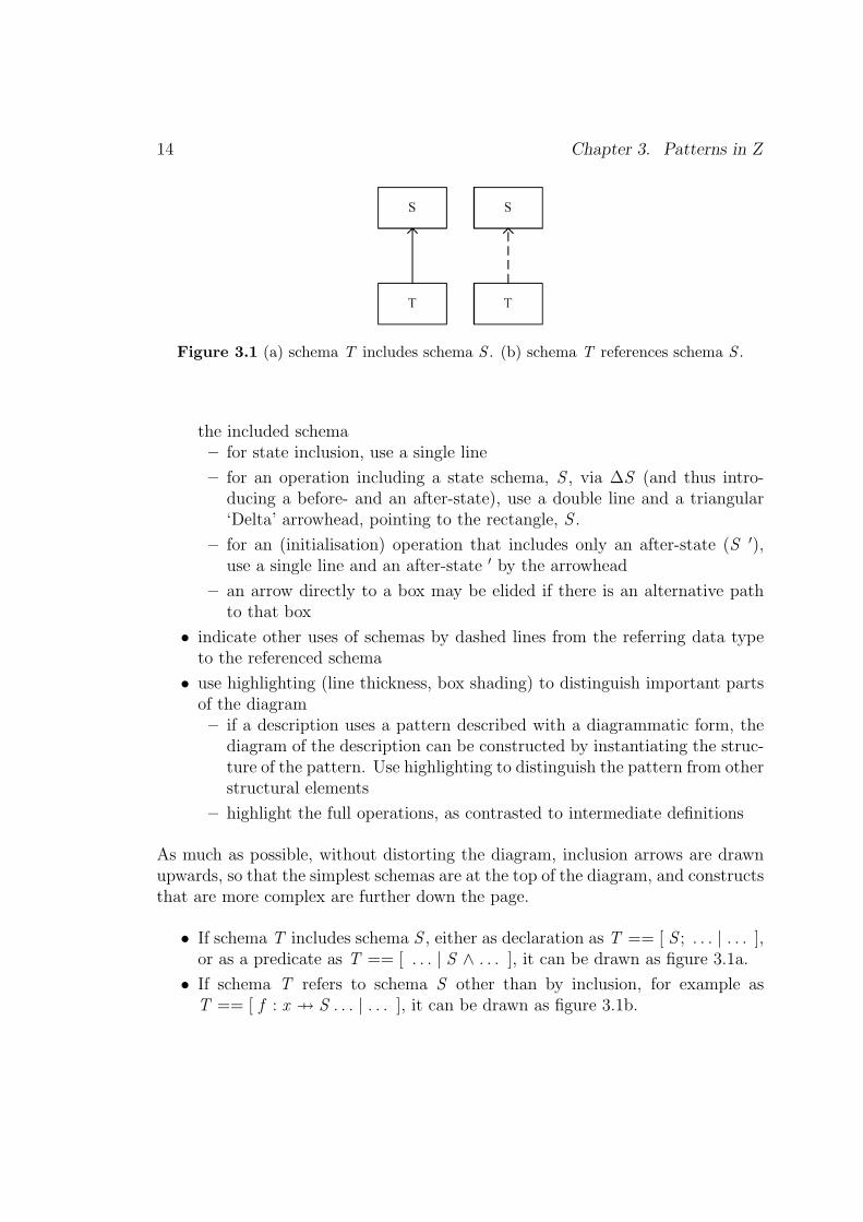
Figure 3.1 (a) schema T includes schema S . (b) schema T references schema S .
the included schema– for state inclusion, use a single line
– for an operation including a state schema, S , via ∆S (and thus intro-ducing a before- and an after-state), use a double line and a triangular‘Delta’ arrowhead, pointing to the rectangle, S .
– for an (initialisation) operation that includes only an after-state (S ′),use a single line and an after-state ′ by the arrowhead
– an arrow directly to a box may be elided if there is an alternative pathto that box
• indicate other uses of schemas by dashed lines from the referring data typeto the referenced schema
• use highlighting (line thickness, box shading) to distinguish important partsof the diagram– if a description uses a pattern described with a diagrammatic form, the
diagram of the description can be constructed by instantiating the struc-ture of the pattern. Use highlighting to distinguish the pattern from otherstructural elements
– highlight the full operations, as contrasted to intermediate definitions
As much as possible, without distorting the diagram, inclusion arrows are drawnupwards, so that the simplest schemas are at the top of the diagram, and constructsthat are more complex are further down the page.
• If schema T includes schema S , either as declaration as T == [ S ; . . . | . . . ],or as a predicate as T == [ . . . | S ∧ . . . ], it can be drawn as figure 3.1a.
• If schema T refers to schema S other than by inclusion, for example asT == [ f : x 7→ S . . . | . . . ], it can be drawn as figure 3.1b.

3.4 Visualisation patterns 15
Figure 3.2 (a) operation Op includes ∆S . (b) several operations Opi include ∆S . (c)initialisation operation Init includes S ′.
• If operation schema Op includes schema S as Op == [ ∆S . . . | . . . ], it canbe drawn as figure 3.2a
• If multiple schemas Si have precisely the same relationships with other schemas,their names can be listed in the same box, thereby drawing attention to theirsimilar structures, as in figure 3.2b
• If initialisation schema Init includes schema S as Init == [ S ′ . . . | . . . ], itcan be drawn as figure 3.2c
Illustration: Figures 4.1, 4.2 show the diagrams used to explain the promotionpattern, and figure 4.3 shows one of its variants; figures 15.1, 15.2, 15.3 show itapplied to the refactored promotion example. Figures 11.1, 11.2 show the diagramsused to explain the refinement pattern. Appendix A.1 shows the diagrams of a largespecification: the Purse specification structure.
Variants:
• The notation can be extended to show conjectures (as in the refinement pat-tern).– conjectures are drawn in an oval, labelled with a suitable name, pointing
to any referenced schemas (see the example in Appendix A.1).
• For large specifications, a diagram may be split into sub-diagrams for clarity.It may be appropriate to draw a separate diagram for each operation, orfamily of operations, reproducing (relevant parts of) the diagram.– schemas or other data type boxes occurring in more than one sub-diagram
are represented as rounded boxes except on the first occurrence (see the

16 Chapter 3. Patterns in Z
example in Appendix A.1).
• If your application uses schemas in some particular way, extend the notationto capture your structure.
�
3.5 Catalogue of Z patterns
In using Z patterns, we have found many variations that were not immediatelyobvious. This could give rise to a very complex catalogue, and further work isneeded on the existing categories. In writing about patterns, we use the followingcategories:
• Presentation patterns : ways of presenting, formatting and laying out Z spec-ifications and documents
• Idiom patterns : styles of writing individual Z phrases
• Structure patterns : ways of structuring small pieces of Z specifications
• Architecture patterns : ways of structuring an entire specification
• Domain patterns : support for specific application domains
• Development patterns : assistance in parts of an engineering process, rangingfrom assistance in selecting appropriate formal methods and for applyingformality at appropriate levels of rigour, to notation-specific developmentpatterns for a particular system.
Under each category we also list certain antipatterns, which illustrate commonlyoccurring counter-examples to good style and best practice.
Themes re-occur in the different categories, and to some extent the divisions amongcategories are arbitrary. For example, patterns relating to naming and formattingexist at most levels. Patterns are context-dependent. So, for example, the particu-lar details of a presentation pattern may be affected by the architecture, style andpurpose of the Z description, and by the application domain.
3.5 Catalogue of Z patterns 17
SUB-CATEGORYCATEGORY Documentation Style UsagePresentation Comment the intention Format to expose structure
Provide navigationName consistentlyOverlong nameOvermeaningful name
Idiom Assemble from chunksRepresenting 1:many mappingsUse free types for unionsMaking a schema bindingMaking a local declarationBelated constraintAbused muBemused lambdaOverloaded numbers
Structure Name meaningful chunks Use generics to control detail Modelling optional elementsName predicates Fortran Modelling product types
Sørensen shorty Modelling membership or flagsBoolean flagPartial precondition
Architecture Morph Promotion
Event traces Delta/Xi
Object OrientationAlgebraic styleGoldilocks chunksUnsuitable Delta/Xi pattern
Domain Application oriented theory Domain specific toolkitsSchema operator toolkit
Development Focus the formality Do a refinement
Use integrated methods AnimateDo sanity checksExpress implicit propertiesApply syntax and type checkingProve rigorouslyProve formally
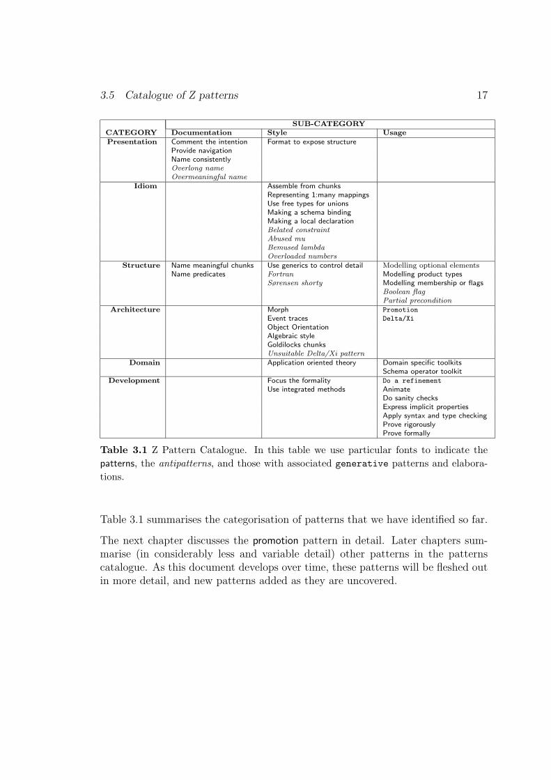
Table 3.1 Z Pattern Catalogue. In this table we use particular fonts to indicate thepatterns, the antipatterns, and those with associated generative patterns and elabora-tions.
Table 3.1 summarises the categorisation of patterns that we have identified so far.
The next chapter discusses the promotion pattern in detail. Later chapters sum-marise (in considerably less and variable detail) other patterns in the patternscatalogue. As this document develops over time, these patterns will be fleshed outin more detail, and new patterns added as they are uncovered.
18 Chapter 3. Patterns in Z
3.6 Patterns for changing the purpose of a Z specification
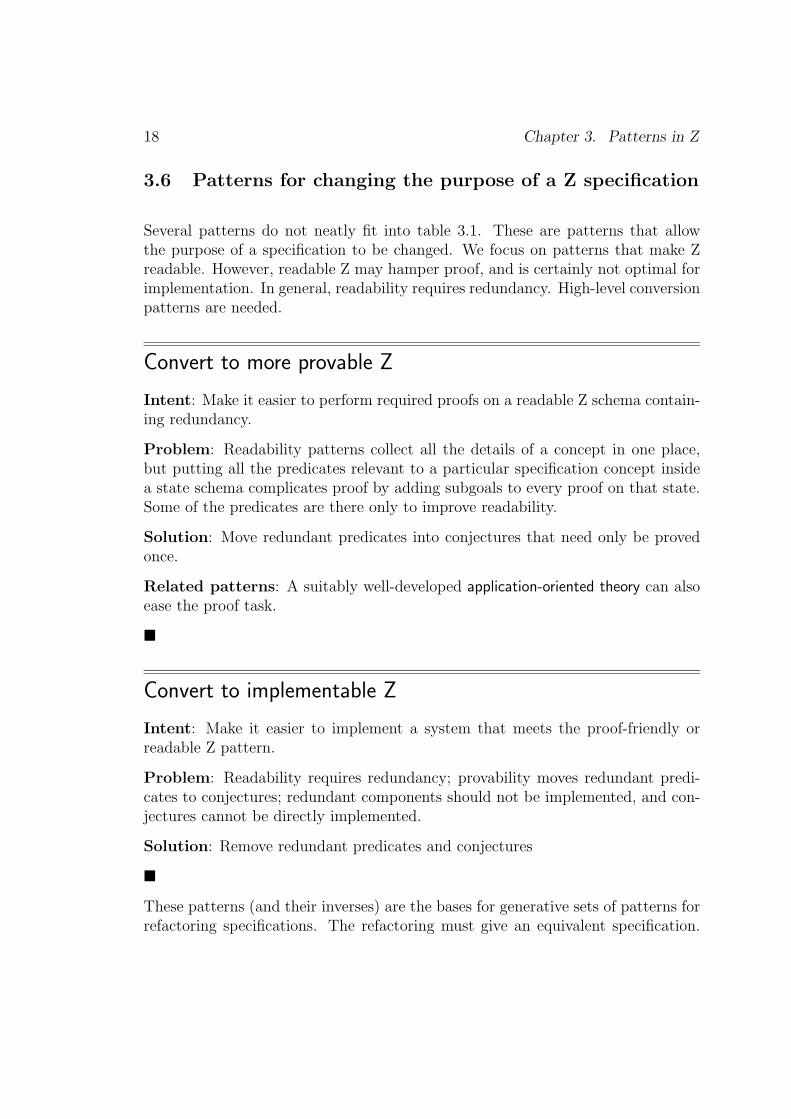
Several patterns do not neatly fit into table 3.1. These are patterns that allowthe purpose of a specification to be changed. We focus on patterns that make Zreadable. However, readable Z may hamper proof, and is certainly not optimal forimplementation. In general, readability requires redundancy. High-level conversionpatterns are needed.
Convert to more provable Z
Intent: Make it easier to perform required proofs on a readable Z schema contain-ing redundancy.
Problem: Readability patterns collect all the details of a concept in one place,but putting all the predicates relevant to a particular specification concept insidea state schema complicates proof by adding subgoals to every proof on that state.Some of the predicates are there only to improve readability.
Solution: Move redundant predicates into conjectures that need only be provedonce.
Related patterns: A suitably well-developed application-oriented theory can alsoease the proof task.
�
Convert to implementable Z
Intent: Make it easier to implement a system that meets the proof-friendly orreadable Z pattern.
Problem: Readability requires redundancy; provability moves redundant predi-cates to conjectures; redundant components should not be implemented, and con-jectures cannot be directly implemented.
Solution: Remove redundant predicates and conjectures
�
These patterns (and their inverses) are the bases for generative sets of patterns forrefactoring specifications. The refactoring must give an equivalent specification.

3.6 Patterns for changing the purpose of a Z specification 19
For example, a schema that is readable and is refactored to aid proof must besemantically identical; only refactorings based on choice patterns are permitted.However, these strict refactorings could take place in a wider context of refactoring.For example, the removal of redundant predicates/conjectures could occur beforeor after refinement or refactoring to generic schemas. (Meaning preservation isconsidered further below.)
Chapter 4
The Promotion Pattern, and itssub-patterns
4.1 Introduction
Before launching into the full Z Pattern Catalogue, in this chapter we describeone particular pattern, promotion, in detail, showing the pattern, its generativesubpatterns, and some of its variations. In the following chapter, we show howto use the generative subpatterns to generate a specification that exhibits thepromotion pattern.
Promotion is an elaboration of the architectural Delta/Xi pattern. Given it is socommon, we choose to class it as a pattern in its own right, too.
4.2 The Promotion pattern
Promotion
Intent: Specify a global system in terms of multiple instances of a local state, andof operations that manipulate a local state.
Problem: A system that is essentially a hierarchy of components has operationsand state at different levels in the hierarchy. This is difficult to specify directly,requiring Z structures such as µ and θ schema bindings.
Example: Some of the examples are presented below, including a banking systemcomprising a collection of accounts; a system for managing a collection of electronic(smart card) purses; an operating system for managing processes on a smart card.
20
4.2 The Promotion pattern 21
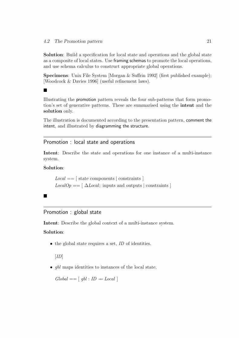
Solution: Build a specification for local state and operations and the global stateas a composite of local states. Use framing schemas to promote the local operations,and use schema calculus to construct appropriate global operations.
Specimens: Unix File System [Morgan & Suffrin 1992] (first published example);[Woodcock & Davies 1996] (useful refinement laws).
�
Illustrating the promotion pattern reveals the four sub-patterns that form promo-tion’s set of generative patterns. These are summarised using the intent and thesolution only.
The illustration is documented according to the presentation pattern, comment theintent, and illustrated by diagramming the structure.
Promotion : local state and operations
Intent: Describe the state and operations for one instance of a multi-instancesystem.
Solution:
Local == [ state components | constraints ]
LocalOp == [ ∆Local ; inputs and outputs | constraints ]
�
Promotion : global state
Intent: Describe the global context of a multi-instance system.
Solution:
• the global state requires a set, ID of identities.
[ID ]
• gbl maps identities to instances of the local state.
Global == [ gbl : ID 7→ Local ]

22 Chapter 4. The Promotion Pattern, and its sub-patterns
�
Promotion : framing schemas
Intent: Provide a context that describes how the global state is updated by theresults of local operations.
Solution: The context, or “frame” is written as a “framing schema”. This es-tablishes the relationship of the state of a local instance to the global state, thenshows how the after-state of an operation on that local instance is used to updatethe global state (the after-state of any suitable global operation) – no details of theglobal operation or the local operation are required; the frame merely deals withstates established by operations defined elsewhere.
The following frame is for any operation that updates the state(s).
• ∆Global and ∆Local introduce the local and global states, pre- and post-operation.
• x? is the global identity of an (existing) local instance.
ΦUpdate∆Global∆Localx? : ID
x? ∈ dom gbl
θLocal = gbl x?
gbl ′ = gbl ⊕ {x? 7→ θLocal ′}
• x? is ascertained to be in the global set of local instances.
• The before-state of Local is the current local state associated with the identity,x?.
• The global state is updated by overriding the gbl function with the mapletfrom x? to the after-state of Local .
The frame for introducing a new local instance to the global state is similar to aninitialisation.
• Declarations are as before, except that there is only an after-state for Local .

4.2 The Promotion pattern 23
ΦNew∆GlobalLocal ′
x? : ID
x? 6∈ dom gbl
gbl ′ = gbl ∪ {x? 7→ θLocal ′}
• x? does not have a mapping in the global state (it is an unused identity).
• The gbl function is updated by set union, adding the mapping from x? to theafter-state of Local .
The frame for an operation to remove a local instance from the global state issimilar, but removes the local instance from the global mapping. The frame is onlyneeded where the removal of a local instance must be verified using operations atthe local level (see [Barden et al. 1994, chapter 19] for details).
�
Promotion : global operations
Intent: Write a global operation in terms of the defined local operations.
Solution: Use schema calculus to extract the relevant local operation (or after-state of a local operation) and conjoin the appropriate framing schema.
GlobalOp == ∃∆Local • ΦUpdate ∧ LocalOp
GlobalNew == ∃Local ′ • ΦNew ∧ InitLocal
Again, deletion is composed in a similar way.
�
Promotion : diagram the structure
Intent: Summarise the structure of the promotion pattern using a diagram.
Solution: The diagram of the structure of promotion is shown in figures 4.1 and4.2. Figure 4.1 shows the structure for the update operations; figure 4.2 shows thespecial form for the initialisation (creation of new local instances).

24 Chapter 4. The Promotion Pattern, and its sub-patterns
Figure 4.1 Structure of the promotion pattern.
Figure 4.2 Structure of the promotion pattern, for the initialisation operation.
�
4.3 Elaboration Patterns for Promotion
The promotion pattern has several well-known elaborations, for coping with casesthat do not fit the plain pattern.
Promotion (elaboration): global constraints

4.3 Elaboration Patterns for Promotion 25
Intent: Add global state components to the collection of local instances
Solution:
GlobalwithStateGlobalpurely global state components
constraints on global stateconstraints relating local states
The addition of global state components may require addition of constraints (a)on the global state, and (b) relating the local instance states; the promoted localoperations may affect the global state through such constraints. There may alsobe operations that act on the global state components alone.
Example: [Stepney et al. 2000] defines a collection of concrete (ie refined from theabstract) electronic purses. The global state has additional mechanisms to controlinteroperability of the purses. The extended global state is:
• conPurse is the global state for the local purses, ConPurse, using identitiesfrom the set, NAME .
• ether and archive are global-only state elements.
ConWorldconPurse : NAME 7 7→ ConPurseether : PMessagearchive : NAME ↔ Message
. . .dom archive ⊆ dom conPurse
• the global state element, archive, is constrained to only known local purses.
All the single purse operations are promoted to the global world level. However,the inputs and outputs from the local operation are not simply mapped into globalinputs and outputs; they are also linked to the ether (the message transport mech-anism) by the framing schema, which extends the framing schemas pattern:

26 Chapter 4. The Promotion Pattern, and its sub-patterns
ΦUpdateCon∆ConWorld∆ConPursem?,m! : MESSAGEname? : NAME
name? ∈ dom conPursem? ∈ ether
θConPurse = conPurse name?conPurse ′ = conPurse ⊕ {name? 7→ θConPurse ′}ether ′ = ether ∪ {m!}archive ′ = archive
In addition to the promoted operations, there are some global-only operations, forexample to add messages in the ether to the archive.
�
Promotion (elaboration): internal identifiers
Intent: Use a native element of the local state as the identifier.
The global identifiers used in promotion are arbitrary. Where the local state hasits own identity, this may be a suitable global identifier.
Solutions: There are two solutions, depending on whether the promotion usesonly internal identity, or uses both internal and global identity redundantly.
Solution 1: Internal identity only
Use Promotion : local state and operations thus:
• identity is included as a native attribute of the local state.
Local == [ self : ID ; . . . ]
• local operations must include a constraint that the identity is not changedby the operation.
LocalOp == [ ∆Local ; . . . | self ′ = self ∧ . . . ]
4.3 Elaboration Patterns for Promotion 27
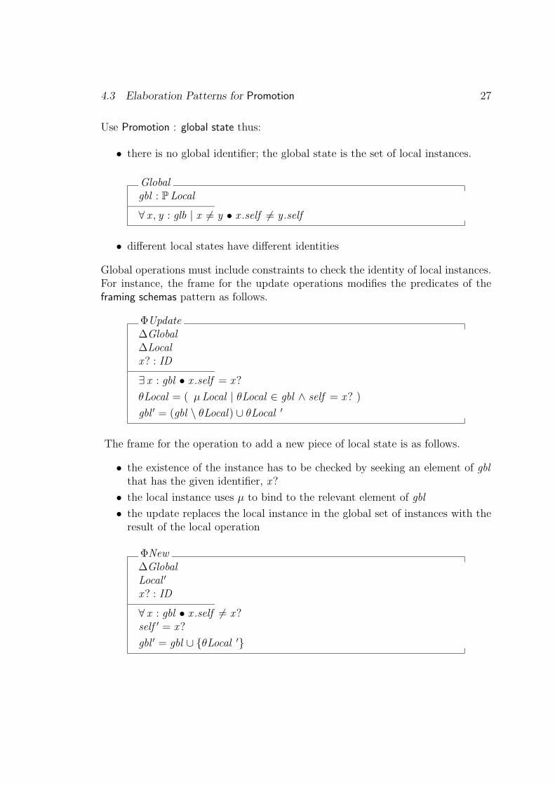
Use Promotion : global state thus:
• there is no global identifier; the global state is the set of local instances.
Globalgbl : PLocal
∀ x , y : glb | x 6= y • x .self 6= y .self
• different local states have different identities
Global operations must include constraints to check the identity of local instances.For instance, the frame for the update operations modifies the predicates of theframing schemas pattern as follows.
ΦUpdate∆Global∆Localx? : ID
∃ x : gbl • x .self = x?
θLocal = ( µLocal | θLocal ∈ gbl ∧ self = x? )
gbl ′ = (gbl \ θLocal) ∪ θLocal ′
The frame for the operation to add a new piece of local state is as follows.
• the existence of the instance has to be checked by seeking an element of gblthat has the given identifier, x?
• the local instance uses µ to bind to the relevant element of gbl
• the update replaces the local instance in the global set of instances with theresult of the local operation
ΦNew∆GlobalLocal ′
x? : ID
∀ x : gbl • x .self 6= x?self ′ = x?
gbl ′ = gbl ∪ {θLocal ′}

28 Chapter 4. The Promotion Pattern, and its sub-patterns
• no pre-existing local state has the given identifier, x?
• the new local state has identifier x?
• the update adds the new local state to the global set
Solution 2: External and internal identities
The local definitions are the same as for the internal-only identifiers.
Use Promotion : global state thus:
• the global function is an injection, because there is a one-to-onecorrespondence between ‘external’ and ‘internal’ names
Globalgbl : ID 7� Local
∀ x : dom gbl • (gbl x ).self = x
• for any instance, external and internal identities are the same.
Illustration: In the concrete specification of the electronic purse, the purse has aname; this is the name that the purse is known by at the external level. The localstate is ConPurse:
ConPurse == [ name : NAME ; . . . | . . . ]
Use Promotion : global state thus:
• ConWorld , uses the same type as the local identifier for the domain of theglobal conPurse.
ConWorldconPurse : NAME 7 7→ ConPurse. . .
∀ n : dom conPurse • (conPurse n).name = n. . .
• every purse’s internal name must be the same as the name by which it isknown in the global system.

4.3 Elaboration Patterns for Promotion 29
The framing schemas pattern is applicable, as the additional constraint is carriedforward in the ∆ConWorld inclusion.
Specimen : Hall’s style [Stepney et al. 1992, chapter 3] combines both thesevariants. It has a set of local states, and it has a derived mapping from (external)identities to local states:
HallStylegbl : FLocalidGbl : ID 7→ Local
idGbl = { l : gbl • l .self 7→ l }
�
Promotion (elaboration): combine promotions
Intent: Specify a system that conforms to the local-global format for the promotionpattern, but has different sorts of local instance.
Solution:
• Each sort of local instance is associated with a separate component of theglobal state.
Globalgbl1 : ID1 7→ Local1. . .gbln : IDN 7→ LocalN
• Constraints could be added as appropriate.
Illustration:
The specification of a Smart Card Operating System [Stepney & Cooper 2000]specifies three types of application instances that the operating system has to con-trol: fixed ISO applications, user programmable applications, and (for modellingreasons) ‘absent’ applications. For technical reasons to do with a particular proof,

30 Chapter 4. The Promotion Pattern, and its sub-patterns
in the specification these three types were combined using a free type, then pro-moted in the simple manner. However, it would be possible to promote the threetypes of local instances individually:
• fixed and user follow the global state pattern.
• absent has no local state other than an identifier, so the internal identifierpattern of promotion is applied.
CardGlobalfixed : ID 7→ Fixeduser : ID 7→ Applabsent : P ID
disjoint〈dom fixed , dom user , absent〉
• The global identifiers for each promotion are drawn from the same set, ID ,so are constrained to be disjoint.
�
Promotion (elaboration): multi-promotion
Intent: Specify a system that comprises multiple instances, but has global opera-tions that may affect more than one local instance.
Solutions: The local state and operations and global state patterns are applied. Theframing schemas include multiple local instances. There are two possible patterns.The first applies when the global operations affect a fixed number of local instances.The second is more general, and applies when the number of local operationsaffected by the global operation is variable or unknown.
Solution 1: A fixed number of local instances (illustrated for two instances, butextensible to as many as are practical or desired).
Use Promotion : framing schemas thus:
• The (otherwise identical) local states are declared twice, distinguished bydecorations. (Note that in ∆Local 1, the decoration applies to the whole∆Local phrase, and thus yields Local 1 and Local ′ 1.)

4.3 Elaboration Patterns for Promotion 31
ΦUpdate∆Global∆Local 1
∆Local 2
x?, y? : ID
{x?, y?} ⊆ dom gblx? 6= y?
θLocal 1 = gbl x?θLocal 2 = gbl y?
gbl ′ = gbl ⊕ {x? 7→ θLocal ′1, y? 7→ θLocal ′ 2}
• the provided identifiers are different instances from the set of identifiers usedin the global system
• each local state instance is bound to one of the input identifiers
• the result of the global operation overrides the global state with the mappingsfrom each identifier to the after-state of the local operation on its local state
Then the global operation becomes
GlobalOp == ∃∆Local 1; ∆Local 2 •ΦUpdate2 ∧ ALocalOp 1 ∧ AnotherLocalOp 2
Illustration 1: This pattern is illustrated in the specification of the electronicpurse transfer operations, chapter 15.
Figure 4.3 gives a diagram of the underlying structure of a multi-promotion, basedon the single promotion diagram. The relevant inclusion arrows are annotated withthe number of local states and operations.
Solution 2: An arbitrary number of local instances
If there is an arbitrary number of local states all affected by the same operation,they can be bundled into a sequence, and the framing schema becomes
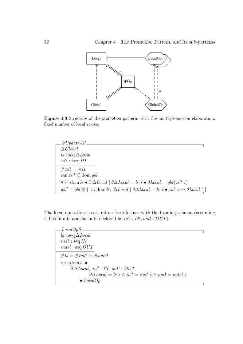
32 Chapter 4. The Promotion Pattern, and its sub-patterns
Figure 4.3 Structure of the promotion pattern, with the multi-promotion elaboration,fixed number of local states.
ΦUpdateAll∆Globalls : seq ∆Localxs? : iseq ID
#xs? = #lsran xs? ⊆ dom gbl
∀ i : dom ls • ∃∆Local | θ∆Local = ls i • θLocal = gbl(xs? i)
gbl ′ = gbl ⊕ { i : dom ls ; ∆Local | θ∆Local = ls i • xs? i 7→ θLocal ′ }
The local operation is cast into a form for use with the framing schema (assumingit has inputs and outputs declared as in? : IN , out ! : OUT ):
LocalOpSls : seq ∆Localins? : seq INouts ! : seq OUT
#ls = #ins? = #outs !
∀ i : dom ls •∃∆Local ; in? : IN , out ! : OUT |
θ∆Local = ls i ∧ in? = ins? i ∧ out ! = outs ! i• LocalOp

4.3 Elaboration Patterns for Promotion 33
Then the global operation becomes
GlobalOp == ∃ ls : seq ∆Local • ΦUpdateAll ∧ LocalOpS
Illustration 2: Consider a local state, Counter that holds an incrementable nat-ural number. An operation on the local state resets the number to zero. Followingthe local state and operations pattern, these are defined:
Counter == [ c : N ]
Reset == [ ∆Counter | c ′ = 0 ]
A global system of counters can be defined using the global state pattern:
CounterSystem == [ sys : NAME 7→ Counter ]
To simultaneously reset all the identified counters to zero (assuming a ΦUpdateAlldefined following the pattern above, but using the names of this example):
ResetSls : seq ∆Counter
∀ i : dom ls • ∃∆Counter | θ∆Counter = ls i • Reset
ResetAll == ∃ ls : seq ∆Counter • ΦUpdateAll ∧ ResetS
This is equivalent to
ResetAll∆CounterSystemxs? : iseq NAME
ran xs? ⊆ dom sys
∀ x : ran xs? •∃∆Counter •
θCounter = sys x ∧ Reset ∧ sys ′ x = θCounter ′
�

Chapter 5
Generating a Promotion, byexample
5.1 Introduction
A generative pattern is one that helps us to construct a specification, rather thansimply describing a structure that a specification could have. We describe thegenerative promotion pattern by the example of a bank account system.
5.2 Starting point: a local state
The starting point for applying the generative pattern is an existing specificationof the local state, here a single bank account:
• A limit is defined as an integer. It represents a global constant for the spec-ification.
limit : Z
• A bank account has an integer balance.
Accountbalance : Z. . .
limit ≤ balance
• At any time, the account balance must be greater than the (lower) limit forthat account.
34

5.3 Step 1: refactor global attributes into the local state 35
Various operations are defined on this single account:
AccountOp == [ ∆Account ; . . . | . . . ]
InitAccount == [ Account ′; . . . | . . . ]
The aim is to specify the whole bank account system, comprising many such singleaccounts. Clearly, this matches the intent of the architecture pattern for promotion:
“Specify a global system in terms of a collection of local states, and ofoperations that manipulate the local states.”
To construct the bank specification, we therefore apply the generative patternsfor promotion. We have a local state, but it does not exactly fit the local stateand operations pattern, because it requires the global constant, limit . Refactoringis used to preserve the meaning of the existing specification, but to make thespecification match the generative pattern.
5.3 Step 1: refactor global attributes into the local state
In the account specification, the limit is intended to be different for different ac-counts. As part of the first refactoring step, it is moved into the local state1.
Accountbalance : Zlimit : Z. . .
limit ≤ balance
The refactoring must preserve the meaning of operations as well as of the state.In the original specification, limit cannot be changed because it is declared ax-iomatically. So in the refactored specification, every operation requires a predicatestating that the limit does not change. This could use the Delta/Xi : change part
1 Note that, if the bank set one limit that was applicable to every account, this could be definedas part of the global state.

36 Chapter 5. Generating a Promotion, by example
of the state pattern, but as there is only one simple variable involved, the predicateis included explicitly.
AccountOp == [ ∆Account ; . . . | limit = limit ′ ∧ . . . ]
The specification now matches the local state and operations pattern.
5.4 Step 2: introduce global state
Following the set of generative patterns, the global state is defined as a collection oflocal states. No identifiers are included in the simple account definition, so a givenset is used at the global level. The global state representing the bank’s accountsis thus a mechanical application of the global state pattern:
[ID ]
Bank == [ acc : ID 7→ Account ]
5.5 Step 3: define framing schemas
Reference to the generative patterns shows that a separate framing schema isneeded for operations that create, remove and change local instances of account.These use the three versions of the framing schemas pattern. The frame for oper-ations that change a local instance is given. (The other framing schema is for anaccount creation, ΦNewAccount .)
ΦUpdate∆Bank∆AccountanId? : ID
anId? ∈ dom accθAccount = acc anId?acc ′ = acc ⊕ {anId? 7→ θAccount ′}
5.6 Step 4: define global operations 37
5.6 Step 4: define global operations
The global operations pattern is used to express the system operations:
BankOp == ∃∆Account • ΦUpdate ∧ AccountOp
NewAccount == ∃Account ′ • ΦNewAccount ∧ InitAccount
There is also an operation, CloseAccount . This is a global operation that removesan instance of account from the global state. It does not require a framing schema,so long as there are no local side conditions on the deletion:
CloseAccount == [ ∆Bank . . . ]
Note that if there were local side conditions, such as the need to check that thebalance was zero, a framing schema would be used.
This results in the promoted bank account specification.
�
5.7 Further promotions
Application of the generative patterns has produced, merely by elaboration oftemplates, a bank specification that is a promotion of the simple account specifi-cation. Note that the ending point of this generation is a specification matchingthe Delta/Xi pattern. This could itself become the local state for a promotion, ifthe next requirement were to specify a chain of banks. In this way, promotion canbe used to generate any hierarchical structure of local states and operations.

Chapter 6
Presentation patterns
6.1 Introduction
Presentation patterns are analogous to low-level coding standards: how to com-ment, how to cross reference, how to format. These patterns seem self-evident topeople used to structured programming or trained to follow company styles forpresentation. However, much published Z is not presented in a consistent man-ner. The pattern solutions given here are based on experience of constructing andproving large formal texts, and the needs of the checkers and reviewers of thesedocuments (eg [Stepney et al. 2000]).
Presentation patterns dictate presentational conventions for the Z documents andcomponents. The pattern details given here relate to Z written for the purpose ofcommunication. Whilst the patterns are still relevant to Z written for other pur-poses, the detailed recommendations would be different. Similarly, several patternsare illustrated for Z written according to the Delta/Xi pattern; the details of thesepatterns would also change if the style of Z were different.
6.2 The presentation patterns
Comment the intention
Intent: Communicate the intent of every part of the specification, with a uniformcommenting style.
Problem: A Z specification that comprises only mathematics is not readable ormaintainable. The mathematics provides a reasonably unambiguous specification,
38

6.2 The presentation patterns 39
but the variable names are an insufficient link to the real world.
Example : An unambiguous but obscure Z schema:
Memoryram, rom : ADDR 7→ BYTEinmap, outmap : PADDR
disjoint〈dom ram, dom rom〉inmap ∪ outmap ⊆ dom ramdisjoint〈inmap, outmap〉
Solution: Provide a commentary in a particular style at a number of levels. Thetext needs to be written and maintained with as much care as the Z, and must addto the value of the mathematical statements: the text is not just a “translation”of the maths.
• If necessary, include an introductory overview of the domain, as context forthe specification; use diagrams to capture the architecture.
• In the body of the specification, write a short sentence that conveys the intentof every Z paragraph, linking to the real world; if the Z is long, provide furthercommentary describing the intent of the internals. Do not simply “translate”the Z into natural language in the comment: if the Z says x ′ = x + 1, acomment like “increment x by 1” adds little value; a comment like “x countsthe number of input events” is better.
• Where a Z paragraph has internal structure (for example, an axiomatic para-graph or schema has a declaration part and a predicate part; a free typedefinition has a number of branches), let the comment structure clearly fol-low that of the Z paragraph, with a readily identifiable part of the commentprovided for each part of the paragraph. For a schema, for example, precedethe Z paragraph with commentary on declarations, follow the paragraph withcommentary on the internal predicates. Use bullet lists to help distinguishthe separate parts.
Illustration:
The schema Memory defines the memory state of the device.• ram describes the dynamic memory, as a mapping from memory
addresses to the byte values they contain

40 Chapter 6. Presentation patterns
• rom describes the read-only memory, as for ram
• inmap, outmap are the memory-mapped input/output memory lo-cations
Memoryram, rom : ADDR 7→ BYTEinmap, outmap : PADDR
disjoint〈dom ram, dom rom〉inmap ∪ outmap ⊆ dom ramdisjoint〈inmap, outmap〉
• ram and rom have distinct address spaces
• the memory mapped i/o lies within ram
• no address is both input and output
�
Format to expose structure
Intent: Expose the structure of each Z phrase by consistent and clear positioningof its component parts.
Problem: Arbitrary formatting of complicated phrases makes a Z document hardto read, because it hinders the readers’ “pattern matching” abilities for recognisingand understanding structure.
Solution: Define and use a consistent formatting style, for example:
• break lines according to the syntactic structure of the phrase: break lines atnodes higher up the syntax tree before breaking at lower nodes
• break lines so that operators are at the beginnings of lines, where they aremore visible
• indent to clarify the structure – increase the indentation of a broken line andalign indentation of parts at similar levels
• place a consistent amount of white space around operators and other smallconstructs; place more around relational operators than functions and gener-ics

6.2 The presentation patterns 41
• place more whitespace around the braces in set comprehensions and aroundthe square brackets in horizontal schemas than around the correspondingbrackets in set extensions and other bracketed constructs
Specimens: Example styles are used in [Stepney et al. 2000], and in the CADiZ[Toyn 2001] and Formaliser [Stepney 2001] pretty-printers.
�
Provide navigation
Intent: Provide supplementary material to allow the reader to locate the declara-tion and uses of any name in the Z document.
Problem: Real specifications can be large (several hundred pages), and a globalname may be used far from its declaration. That declaration provides context, typeinformation, and constraints, all of which are needed to understand the name. Ad-ditionally, particularly when modifying a specification, an investigation of all usesof a name is important. Tools provide on-line navigation (from full hyperlinking,down to using grep), but it can be hard to discover the appropriate declaration orall uses in a large paper document.
Solution: Provide a complete index of global name declarations. Global namesinclude schema components, indexed as, for example, compName; SchemaName.If a specification is split across several documents, perhaps with a domain-specifictoolkit in a separate document, provide indexing into all the documents. (The well-known Mathematical Toolkit names do not usually need to be indexed.) Consideralso providing an index of where global names are used.
Related patterns: Name consistently, to give clues to the meaning of a name. Atthe architectural levels, Name meaningful chunks and Use Goldilocks chunks ensureany local names have use and declaration simultaneously visible.
Specimens: [Stepney et al. 2000] has a full index; the CICS project [Wordsworth1987] uses marginal cross-referencing. [Arthan 2000]’s convention is to use boldfont when declaring a global name, then ordinary font when using it.
�
Name consistently

42 Chapter 6. Presentation patterns
Intent: Use a naming convention that conveys structural information.
Problem: Names are important, and arbitrary component names can confuse anddisorient the reader. Even an originally good naming convention can be erodedduring maintenance.
Solution: Define, document and use a naming convention for a specification. Theconvention may include type information, scope information (for example, shortnames only for local scope or generic formal parameters), intent information (asgiven by comment the intent), and a link to other names with a related intent (forexample, by consistent use of prefixes, suffixes or subscripts).
Related patterns: Delta/Xi has a convention for inputs, outputs and state changes.Promotion has a convention for framing schema names. A complex convention canlead to the overlong name antipattern.
Specimen: ZIP [Barden et al. 1994, chapter 8] introduces a simple convention fortypography of names in a Z specification.
�
6.3 Presentation antipatterns
Overmeaningful name
Intent: Properties implied by names should not be relied upon until made explicitin the Z text.
Problem: An apparently meaningful name is declared, but is never constrainedto have the property its name suggests.
Example: A declaration even : N is made, and is never followed by any furtherconstraint on the values of even.
Solution: Do not build more into the name than the mathematics can deliver.The name should be ‘meaningful’ in the way it links to the real world, not ‘over-meaningful’ in implying restrictions that do not actually hold.
Variants: When using lightweight formality, it can be useful to build meaning intothe name that is not fully supported by the intentionally-abbreviated mathematics.

6.3 Presentation antipatterns 43
In such cases, comment the intent carefully, pointing out this fact.
�
Overlong name
Intent: Use names that enhance the readability of the specification.
Problem: Long names can cause readability problems: they may cause overlengthlines and linebreaks that detract from readability; if they differ by only a few letters,they may be difficult to distinguish; they may hinder the reader’s recognition ofthe mathematical patterns in use.
Solution: Use names that are long enough to be meaningful, but short enough tobe readable. Make similar names more distinguishable by placing their differencesat the beginning, rather than the end, of the word.
�

Chapter 7
Idiom patterns
7.1 Introduction
Z is a powerful notation, and there can be several ways of achieving a particularend. It is often useful to choose a particular idiomatic way of doing something,and sticking to it. The idiom itself then becomes part of the vocabulary.
7.2 The idiom patterns
Assemble from chunks
Intent: Construct a complex Z structure from understandable chunks.
Problem: There can be a large gap between the high level concepts that we needto express and the low level language elements that Z provides for their expression.Often a complicated set needs to be defined, with only fairly primitive constructorsavailable.
Solution: Apply the “divide and conquer” principle. Specify simple componentsets that make sense in isolation, and then combine them using MathematicalToolkit operators, domain-specific toolkit operators, or schema calculus, as appro-priate, into the complicated whole.
This “assembly” might join parts together (union, schema disjunction, concatena-tion), remove parts (intersection, schema conjunction, set difference, restriction,projection, filtering), supersede some parts (relational override), connect partsstepwise (relational and schema composition, piping, relational closure), and so
44

7.2 The idiom patterns 45
on. Ensure that the simpler parts themselves make sense in isolation (“all smallor medium widgets, except blue ones”).
Constraint: Sometimes things really are so baroque that they cannot be brokendown into simpler chunks any bigger than individual elements. If this is so, askwhy. If there is no need to follow an existing implementation or standard, trysimplifying the specification so that it can be chunked. At least try to isolate thebaroque part in a chunk of its own, with copious commentary: lotsOfEasyStuff ⊕smallButHorrible.
Related patterns: At higher structural levels, equivalent compositional patternsare name meaningful chunks and Goldilocks chunks. The naming of chunks uses thepresentation pattern name consistently. The goal of the Z text is emphasised by useof the presentation pattern comment the intention, at both the component and com-posite levels, but paying particular attention to any smallButHorrible chunk. TheDelta/Xi : disjoin errors sub-pattern uses the schema calculus to combine varioussub-operation schemas.
�
Representing 1-many mappings (choice)
Intent: Choose how to model a relationship with a set of target values.
Problem: Each element of X is related to a set of values of Y . There are severalways to model this.
Solution choice:
1. Representing 1-many mappings : using a target setf : X 7→ PY : this precisely expresses the problem, and is most useful if thevarious ys associated with a particular x are being manipulated explicitly:they are accessible as y ∈ f x . This formulation is difficult to use in a morealgebraic style, where there is frequent need to flatten sets of range sets usinggeneralised unions.
2. Representing 1-many mappings : using a relationfr : X ↔ Y : this expresses the underlying structure, and tends to be mostuseful if the relation is being manipulated as a whole, in an algebraic style.Extraction of explicit range elements requires use of the relational image,fr(| {x} |), in place of simple function application, f x .
46 Chapter 7. Idiom patterns
3. Representing 1-many mappings : using the inverse mappingfinv : Y 7→ X : if the inverse is a function, this may be a better model of therelationship.
Constraint: The first two choices are not exactly isomorphic: the functional formcan distinguish absence from the mapping, x1 6∈ dom f , from mapping to the emptyset, f x2 = ∅, whereas the relational form cannot.
�
Making a schema binding (choice)
Intent: Specify a particular schema binding.
Problem: A particular schema binding has to be specified, that is, values need tobe associated with the variables (foo and bar) of an instance of the schema (θS ).There are several ways to do this; one involves using µ in an idiomatic way.
Solution choice:
1. Making a schema binding : ISO-ZIn ISO-Z, schema bindings can be written directly, as in 〈| foo == x , bar ==y |〉,
2. Making a schema binding : ZRMIn ZRM, schema bindings cannot be easily written; a mu-expression is oftenused, as in µ S • foo = x ∧ bar = y .
�
Making a local declaration (choice)
Intent: Use local declarations in an expression or predicate.
Problem: There are several ways to do this; one involves using µ in an idiomaticway.
Solution choice:
1. Making a local declaration : let-expressionIn ZRM and ISO-Z, a let-expression can be used, as in let x == foo; y ==

7.3 Idiom antipatterns 47
bar • expr . In ISO-Z a µ expression can be used in an idiomatic way to getan equivalent construct, as in µ x == foo; y == bar • expr .
2. Making a local declaration : ZRM let-predicateIn ZRM, a let-predicate can be used, as in let x == foo; y == bar • pred .
3. Making a local declaration : ISO-Z quantifierISO-Z has no let-predicates; an existential quantifier can be used in an id-iomatic way to get an equivalent construct, as in ∃ x == foo; y == bar •pred .
�
Use free types for unions
Intent: Bundle together different types so they can be treated uniformly.
�
7.3 Idiom antipatterns
Belated constraint
Intent: Avoid separating named elements and parts of their definition.
Problem: A global name is declared and, much later in the specification, is con-strained. Any use of the name between declaration and constraint is subject tothis constraint, but the reader is not yet aware of it.
Example: A global name is declared, say as n : N. n is used liberally in thespecification, but something seems a little off key. We read on, hopefully, andmany pages later, we discover the global constraint n ∈ even. All our laboriouslybuilt-up understanding of the specification is destroyed in that one line (or, morelikely, it suddenly becomes clear why nothing really made sense until now!)
Solution: Specify any constraints along with the declaration, in the same para-graph or as close to it as possible. If it really is not possible to write the constraintwith the declaration, put a clear comment at the declaration, with a forward ref-erence to the constraint.

48 Chapter 7. Idiom patterns
Constraint: Some proof tools require each paragraph to be a conservative ex-tension of the specification, because that makes certain sanity check proofs easier;thus they disallow belated constraints. Also, purposes other than communicationmay dictate different patterns (see convert to provable Z, above).
�
Abused mu
Intent: Make the specification as accessible as possible to all levels of readers.
Problem: An expression containing µ is almost always unreadable, except to veryexperienced specifiers.
Solution: Confine the use of µ to idiomatic ways, such as making a schema binding(and possibly in making a local declaration, but let is to be preferred). If it is deemednecessary to use µ in other contexts, comment the intention very carefully.
Specimens: [Barden et al. 1994, chapter 24] describes some uses and abuses of µ.
�
Bemused lambda
Intent: Make the specification as accessible as possible to all levels of readers.
Problem: In some contexts, experienced formalists use unnamed lambda func-tions. This can considerably reduce the effort of specification, by making it clearthat a function is being defined, and in not requiring the invention of a name.However, the type of the function is not explicit, and the use of lambda functionsis often confusing to less experienced readers.
Solution: Comment the intention of such lambda functions very carefully. Considerwhether to express implicit properties (of the function’s type).
�
Overloaded numbers
Intent: Exploit the Z type system and typechecking tools to catch as many errorsas possible.

7.3 Idiom antipatterns 49
Problem: Subsets of N or Z are often used as convenient models of labels andidentifiers in specifications, but a typechecker cannot catch cases where the wrongkind of label is being used.
Solution: Use given sets and free types, rather than subsets of N or Z, wherepossible.
Specimen: [Brown 1979] quotes his eighth deadly sin as “to use numbers forobjects that are not numbers”.
�
Chapter 8
Structural patterns
8.1 Introduction
At the intermediate level, structural patterns guide the selection and constructionof components of the formal description. Whilst some of these patterns repre-sent presentational issues, several capture solutions to potentially hard practicalproblems.
8.2 The structural patterns
Use generics to control detail
Intent: Use type representations that are consistent throughout a developmentbut that, at any phase of development, carry the details relevant to only that levelof abstraction.
Problem: Z texts need to refer to many kinds of real-world and/or implement-ation-level data. Full specification of the data types clutters high-level Z descrip-tions and usually over-constrains possible implementations. Introducing more con-crete types in a lower-level specification forces an expensive data-refinement proofobligation. In some cases it is not possible to introduce the desired schema, becauseof a recursive structure.
Example: A specification needs to represent personal details and addresses. Therepresentation depends on the level of detail required, and the planned use of thespecification. At the abstract level, [NAME ,ADDRESS ] is a sufficient model. At
50

8.2 The structural patterns 51
a more concrete level, however, it becomes necessary to define a (possibly complex)internal structure for NAME and ADDRESS .
Solution: Make the specification generic in the types that will need to be elab-orated. This abstract representation does not impose unnecessary constraints onthe specification. Later, define concrete types with the additional detail, and useit to instantiate the generic specification.
Illustration: An abstract Customer has a name and address , of generic type.
Customer [NAME ,ADDRESS ]name : NAMEaddress : ADDRESS
Some customers are personal (as opposed to companies) and have a name withthe format of a PersonalName (as opposed to a company name, say), a particularconcrete form.
PersonalNametitle, forename, surname : String
Personal customers have a HouseAddress . Different countries use a different formof CODE , so that is left generic here.
HouseAddress [CODE ]house : N1
street , town, country : Stringcode : CODE
In the UK, the address code is a Postcode (details omitted)
Postcode == . . .
So a PersonalUKCustomer has a PersonalName, and HouseAddress instantiatedwith a Postcode.
PersonalUKCustomer == Customer [PersonalName,HouseAddress [Postcode]]
Variants:

52 Chapter 8. Structural patterns
1. A generic schema can be used in a recursive free type definition (suggestedby Rob Arthan).
Node[T ] == [ left , right : T ; value : N ]
TREE ::= leaf | node〈〈Node[TREE ]〉〉TreeNode == Node[TREE ]
2. Type-constrained generics [Valentine et al. 2000] are an extension to Z thatallows definitions to require their generic parameters to be instantiated onlywith schemas having certain signatures; this permits a wider use of genericsin Z specifications.
Specimens: Instantiation of generics with more concrete types is demonstratedin [Polack & Stepney 1999]. Other variants appear in [Flinn & Sørensen 1992] andvarious toolkit definitions.
�
Modelling optional elements (choice)
Intent: Provide a type that allows variables to take an unknown or optional value.
Problem: Some system domains use a type-correct marker, a null , to represent avalue that is known to be inapplicable in certain circumstances, but Z sets do nothave such a concept, and using powersets with null == ∅ is over-complicated.
Example: A database relation comprises n-tuples, each of which has a value foreach component attribute. If a particular attribute is not applicable to a particularn-tuple, the null value is inserted.
Solution choice:
1. Modelling optional elements : free typeUse a free type to add the optional element
OPTTYPE ::= null | present〈〈TYPE 〉〉
Several different “null” elements can be accommodated, and can even havesome structure, such as null〈〈ID〉〉. However, it clutters the name-space withnew names for each new optional type, and has a wordy syntax.
2. Modelling optional elements : generic optional[d’Inverno & Priestly 1995] give a compact treatment of the problem. They

8.2 The structural patterns 53
define a generic operator (on types) with the characteristics of the optionality;this can be instantiated in the declaration of any variable that can take anoptional value.
optional [X ] == { a : PX | #a ≤ 1 }relation(defined )relation(undefined )
[X ]defined , undefined : P optional [X ]
∀ a : optional [X ] •defined a ⇔ a = 1∧ undefined a ⇔ a = 0
∀ a : optional [X ] | defined a •the a = ( µ x : X | x ∈ a )
Being generic, this approach introduces the new names optional , defined ,undefined , and the, to the name-space only once, not once for each newoptional type.
�
Name meaningful chunks
Intent: Improve comprehensibility of a large or complex structure by building itfrom identifiable components.
Problem: A reluctance to separate out and name components that are used onlyonce can lead to complex structures. The intent of the structure is not apparentwithout careful deconstruction.
Solution: Construct and name components which are meaningful in themselves,even if they are used only once.
Related Patterns: Assemble from chunks is the similar low level idiom pattern.Predicates are covered by name predicates. The Delta/Xi : disjoin errors sub-patternuses the schema calculus to combine various named sub-operation schemas.
�
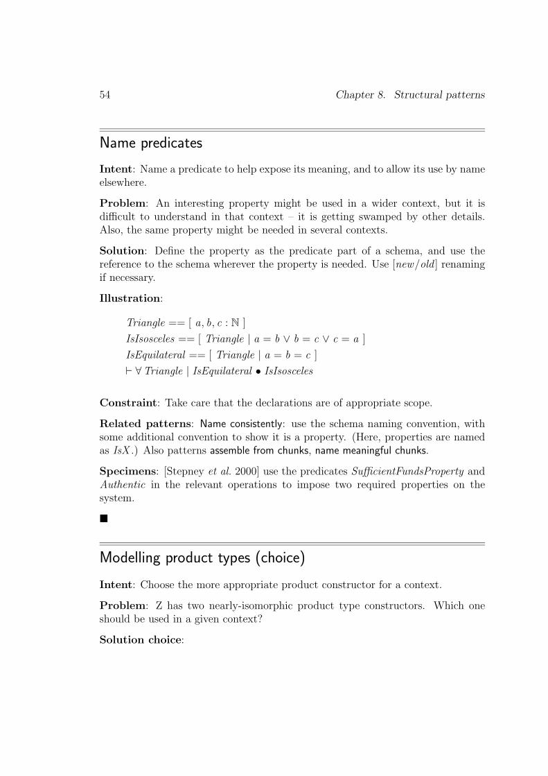
54 Chapter 8. Structural patterns
Name predicates
Intent: Name a predicate to help expose its meaning, and to allow its use by nameelsewhere.
Problem: An interesting property might be used in a wider context, but it isdifficult to understand in that context – it is getting swamped by other details.Also, the same property might be needed in several contexts.
Solution: Define the property as the predicate part of a schema, and use thereference to the schema wherever the property is needed. Use [new/old ] renamingif necessary.
Illustration:
Triangle == [ a, b, c : N ]
IsIsosceles == [ Triangle | a = b ∨ b = c ∨ c = a ]
IsEquilateral == [ Triangle | a = b = c ]
` ∀Triangle | IsEquilateral • IsIsosceles
Constraint: Take care that the declarations are of appropriate scope.
Related patterns: Name consistently: use the schema naming convention, withsome additional convention to show it is a property. (Here, properties are namedas IsX .) Also patterns assemble from chunks, name meaningful chunks.
Specimens: [Stepney et al. 2000] use the predicates SufficientFundsProperty andAuthentic in the relevant operations to impose two required properties on thesystem.
�
Modelling product types (choice)
Intent: Choose the more appropriate product constructor for a context.
Problem: Z has two nearly-isomorphic product type constructors. Which oneshould be used in a given context?
Solution choice:

8.2 The structural patterns 55
1. Modelling product types : schemaComponent names are meaningful (for example, memory .register would referto the register component of the schema binding memory). This fits the in-tention of name meaningful chunks. However, constructing particular schemabindings is relatively verbose. Use a schema product where the names conveysome helpful meaning, and where component selection is common.
2. Modelling product types : Cartesian productComponents are located by position (for example, memory .3), which commu-nicates little meaning. However, the tuple construction syntax is terse. Usea Cartesian product when terseness is valuable, for example, the main use ofthe product is writing explicit values, as in algebraic style operator definitions.Use a Cartesian product when there are no meaningful names to be had, forexample, if the components are bundled into a tuple simply in orer to returnmultiple results from a function.
Specimens: of schemas: [Polack et al. 1993], [Mander & Polack 1995]; of tuples:many Mathematical Toolkit definitions
Variants: In ZRM, schema components can be directly selected, as in S .foo,but schema bindings cannot be directly written (a mu-expression is often used,following making a schema binding 2); tuples can be directly written, as in (x , y , z ),but their components cannot be directly selected (a lambda-expression with acharacteristic tuple is often used, as in λ x : X ; y : Y ; z : Z • z ). ISO-Z allowsschema bindings to be directly written (see making a schema binding 1), and tuplecomponents to be directly selected, as in t .3, but there is still a difference in theterseness of construction.
�
Modelling membership or flags (choice)
Intent: Provide a meaningful distinction between statuses.
Problem: When defining state indicators, specifiers sometimes define types whichare implementation-oriented, and are at once too general and too restrictive. Inparticular, a free type definition of BOOLEAN 1 is often overloaded (used to rep-resent too many different kinds of statuses) and unhelpful (it cannot be used as apredicate, and cannot be extended to take further values).
1 Z does not have a built-in Boolean type; predicates are either true or false.

56 Chapter 8. Structural patterns
Example:
BOOLEAN ::= btrue | bfalse
switchon : BOOLEAN
if switchon = btrue then . . .
Solution Choice:
1. Modelling membership or flags : free typeDefine each set of related statuses as a free type, with each status beingrepresented by a branch with a meaningful name. The number of branchescan be extended as more statuses are uncovered.
2. Modelling membership or flags : boolean schemasUse the schemas True == [ | true ]; False == [ | false ] as predicates, anddefine Boolean == {True,False}.
Illustration 1:
SWITCH ::= on | off
switch : SWITCH
if switch = on then . . .
Note that this representation can easily be extended, for example, to
SWITCH ::= on | off | broken
Illustration 2:
switch : Boolean
if switch then . . .
Related patterns: A Boolean type should be used with caution; it may signalthe Boolean flag antipattern, indicating the specification is insufficiently abstract.
�
8.3 Structural antipatterns
Fortran

8.3 Structural antipatterns 57
Intent: Be as abstract as possible, avoiding over-specification of details such asalgorithms
Problem: “Fortran programs can be written in any language”
�
Sørensen shorty
Intent: Use the Mathematical Toolkit to help write compact definitions, but don’tbe too clever2
Example: The ZRM Mathematical Toolkit definition of squash is
∀ f : N1 7 7→ X •squash f = f ◦ ( µ p : 1 . .#f �→ dom f | p ◦ succ ◦ p∼ ⊆ ( < ) )
Illustration: The ISO-Z Mathematical Toolkit definition of squash is
∀ f : Z 7 7→ X •squash f = { p : f • #{ i : dom f | i ≤ p.1 } 7→ p.2 }
�
Boolean flag
Intent: Be specific about toggle- and selector-values: avoid the use of Boolean-valued variables.
�
2 Named in honour of one of the pioneers of Z, Ib Sørensen, famed for his concise definitions.Name used with permission!
Chapter 9
Architecture patterns
9.1 Introduction
Architecture patterns capture conventional ways of using the formal language toproduce an overall architecture that achieves the goals of the developer. Somearchitecture patterns draw on conventional wisdom in the construction of largeor complex computer programs: such patterns are generalisable to other formalnotations. Other patterns relate specifically to Z.
Architecture patterns help to express a description in Z. They also help the readerof the text. For example, the recognition that a particular form of expression is anarchitecture pattern allows the reader to concentrate on the system specific detailrather than the structure of the Z – this would apply to, for example, Delta/Xi: change part of the state, Delta/Xi : project away clutter, and promotion, amongothers.
Even experienced formalists find it difficult to take on a new style of specification.This can result in inappropriate use of common architecture patterns, and inelegantspecifications that do not map cleanly onto the solution architecture. The Delta/Xipattern [Barden et al. 1994, chapter 3] is widely (too widely?) used.
9.2 The architecture patterns
Morph
Intent: Specify the translation of one formal entity into another.
58

9.2 The architecture patterns 59
Problem: Some problems are cast in terms of one entity being translated intoanother, where this translation is independent of any hidden state – that is, thetranslation always provides the same result.
Example: A compiler translates source code into target code; it translates sourcecode into error messages during syntax and static analyses.
Solution: Specify a function (or relation) that translates the first entity into thesecond. Use the structure of the entity being translated to break the function def-inition into named meaningful chunks. (In particular, if the entity being translatedis of free type, break the function definition into the free type branches.)
Constraint: Any variation in the translation must be encoded as a parameter ofthe function, or emerge as the result of a non-deterministic relation. The transla-tion function can be used within a Delta/Xi state or operation schema, with statevariables being used as arguments, to provide such variation.
Related Patterns: Assemble from chunks, for defining a complicated or a multi-part translation. Modelling 1:many relations – if morph is providing the steps to becombined in a more general Unix-style pipe-and-filter specification, then make therelational choice.
Specimens: [Stepney 1993] specifies a compiler using meaning functions to de-fine the high- and low-level languages, and a compilation function to define thetranslation.
�
Morph : diagram the structure
Intent: Summarise the structure of a Morph specification using a diagram.
Problem: Since a Z specification is presented ‘bottom-up’ (declaration before use)and can be factored into many pieces, it may become difficult to ‘see the wood forthe trees’.
Solution: Construct a diagram to record the structure of the functions, highlight-ing how their inputs and outputs are related.
Do not worry over-much about being consistent and complete, and about distin-guishing every small difference: the purpose of the diagram is to be a graphicaloverview of structure, not to be an alternative formal notation.

60 Chapter 9. Architecture patterns
The following components are recommended:
• draw the function being diagrammed as a grey background rectangle
• draw named functions used in the definition as named rectangles
• draw other functions, or parts of the specification that may be considered asfunctions, as named ovals (these may indicate refactoring opportunities)
• draw inputs as arrows into the box; if the input is a constant, draw it ema-nating from a constant source (indicated by a blob)
• draw outputs as arrows out of the box if the output is not used, draw it fallinginto a sink (indicated by a blob)
• label lines with any intermediate names introduced in the specification, asappropriate
• use different line styles to highlight different argument types
• ‘explode’ a product type input into its components (indicated by an ‘explod-ing star’ symbol)
• copy (‘fork’) an argument into several different functions (indicated by a ‘plus’symbol)
• draw curried functions as nested functions, if necessary
As much as possible, without distorting the diagram, let the arguments flow fromleft to right. First minimise the number of crossing lines, and then as far as possiblehave the arguments entering the boxes in the right order.
Illustration: Figures A.4, A.5 show the morph diagrams (including the compo-nents listed above) of a large specification: two functions in a compiler specification.
�
Event traces
Intent: Specify an event-based system in terms of traces (with or without addi-tional details of state and operations).
Problem: A system that is described in terms of possible events and their allowedsequences is not primarily composed of state and operations, so it is difficult tocapture in a Delta/Xi model.
Solution: Specify the system using an event trace model. Specify the events, anddescribe the system as the set of traces (sequences of events) that are allowed or
9.2 The architecture patterns 61
disallowed.
Illustration:
• The system comprises events, with no elaboration.
[EVENT ]
• There are three separate types of event:
a, b, c : EVENT
• The SYSTEM comprises all event traces that have fewer a events than cevents
SYSTEM == { s : seq EVENT | #(s � {a}) < #(s � {c}) }
Constraints:
1. If modelling infinite sequences of events, the definitions in the MathematicalToolkit needs supplementing: it defines only finite sequences.
2. A more complex model is needed if properties such as fairness or timingmust be enforced. For pure event-trace systems, other formalisms such asCSP[Hoare 1985] are more appropriate than Z.
Variant: An event trace model can be combined with, or refined into, a Delta/Ximodel where operations are used to add detail of the events. If the system is definedin terms of constraints on individual traces (as in the illustration), the trace can beincluded as a state component, with each operation adding the relevant event tothe trace and obeying the constraint. However, if the system is defined in terms ofproperties across traces, much machinery is needed to do the combination formally[Cooper & Stepney 2000].
Related Patterns: Assemble from chunks, for defining a complicated set of se-quences.
Specimens: [Cooper & Stepney 2000] specifies a segregation property as a prop-erty of the system’s traces; [Heisel & Souquieres 1999] captures system requirementsas a trace model.
�

62 Chapter 9. Architecture patterns
Delta/Xi
Intent: Specify a system characterised by discrete state elements and the opera-tions on those states.
Solution: We do not go into details here. The style, sometime also called “Stateand Operations style”, appears in most Z texts and papers, for example [Barden etal. 1994, chapter 3] (where it is called “the Established Strategy”). Its two mainsub-patterns are
• Delta/Xi : state
• Delta/Xi : operations
Some more of its sub-patterns are given below.
Technical note: the so-called ‘Delta/Xi naming conventions’ are not pure conven-tions, because some semantics are defined. The dash (after-state of a variable)has semantics through schema composition; ? and ! (input and output variables)have semantics through ZRM’s pipe, and ISO-Z gives a default semantics for the∆ and Ξ schema names (and is motivation for the Delta/Xi : strict conventionsub-pattern).
Related Patterns: Name consistently when using the conventions of the style.Change part of the state when specifying which part of the state the operationschange. Promotion allows local state and operations to be promoted to global stateand operations. The partial precondition antipattern reveals a common error in theDelta/Xi total operation approach: a failure to cover all preconditions in the fulloperation.
�
Delta/Xi : disjoin errors
Intent: Structure the operations in terms of correct and erroneous behaviour.
Problem: An operation may behave normally only under a small precondition.Covering all the exception cases can lead to a large, unwieldy definition that ishard to understand.
Solution: Construct operation schemas for each correct and incorrect invocation.

9.2 The architecture patterns 63
Combine them using schema calculus disjunction:
FullOp == Op1Ok ∨ Op2Ok ∨ Op1Error ∨ Op2Error ∨ OtherErrors
Note that this construction can introduce non-determinism into the specification,where preconditions of the disjuncts overlap.
�
Delta/Xi : strict convention
Intent: Use the ∆/Ξ naming convention strictly, to avoid surprising the readerwith hidden constraints.
Problem: If a schema such as ∆S is encountered, it usually has a conventionaldefault meaning, S ∧ S ′, but it may have been defined to mean something else(say an extra predicate or state component added). This can lead to confusion forthe reader expecting the default meaning.
Solution: Adhere strictly to the convention. ∆S always means S ∧ S ′; ΞS alwaysmeans [ ∆S | θS = θS ′ ]. Consequently, it is never necessary to explicitly define∆S or ΞS , as they always have their default meanings.
�
Delta/Xi : change part of the state
Intent: Define an operation that changes only a small part of the state.
Problem: In a Delta/Xi specification with a large state, S , most operations specifychanges to only part of that state. ΞS constrains the entire state to be unchanged– it is usually too strong. ∆S puts no constraints on the state change – it is usuallytoo weak.
Solution: Include a predicate of the form ΞS \ (x , y) in the operation schema,which constrains the state components not in the hiding list to be unchanged.
Variants:
1. Unlike ISO-Z, ZRM does not allow schema expressions to be used as pred-icates. In ZRM this pattern can be used by defining a new schema as therequired hiding, and using a reference to the new schema as a predicate.

64 Chapter 9. Architecture patterns
2. If the full state has been partitioned into Goldilocks chunks sub-states, theunchanging sub-states can be expressed as ΞSubS , and the changing sub-state by ∆S . If the partition is done cleanly, most operations affect only afew sub-states; change part of the state is used on these sub-states.
Related patterns: Name predicates describes using a schema as a predicate.Delta/Xi : strict convention says why extra constraints should not be built into the∆S schema
�
Delta/Xi : project away clutter
Intent: Retain a clear signature when introducing auxiliary variables to a Zschema.
Problem: In a Delta/Xi specification, local variables can be introduced by exis-tential quantification in the predicate part, but that makes the predicate difficultto read, and the variables are not then available to other schemas if the definitionis being assembled from chunks. Alternatively, local variables can be introducedin the declaration part, but then they are visible in the final schema, so are notstrictly local, pollute the name-space, and potentially cause type problems.
Example:
T 1 == [ S ; x : X | predX ]T 2 == [ S ; x : X ; y : Y | predXY ]S0 == T 1 ∧ T 2
has the x and y visible in S0’s signature, whereas
T 1 == [ S | ∃ x : X • predX ]T 2 == [ S | ∃ x : X ; y : Y • predXY ]S0 == T 1 ∧ T 2
has the right signature for S0, but does not merge the x in T 1 with that in T 2.
Solution: Introduce the local variables in the declaration part of the relevantschema(s). Use Z projection, �, to list only the elements that must be visible.

9.2 The architecture patterns 65
Illustration:
T 1 == [ S ; x : X | predX ]T 2 == [ S ; x : X ; y : Y | predXY ]Sfin == (T 1 ∧ T 2) � S
• sfin has all the variables of T 1 and T 2, with appropriate merges, but onlythe declarations of S are visible.
�
Delta/Xi : hide a state component
Intent: Take a state component out of the visible signature of a schema. (Z hidingoperator.)
�
Delta/Xi : partial precondition
Intent: Write total operations.
Problem: Often, when using the Delta/Xi pattern, operations are intended to betotal, but are mistakenly partial, because some case has been accidentally omitted.
Solution: Check that the operation is total, by calculating the precondition. Addany further necessary cases in the predicate part.
�
Object orientation (choice)
Intent: Specify the system in an object-oriented style.
Problem: Object-oriented structuring is appropriate to a development, yet thereseems to be no natural way to use such a style in conventional formal methodssuch as Z.
Solution Choice: Depending on how much of the object-oriented machinery isneed, several approaches are possible.

66 Chapter 9. Architecture patterns
1. Object orientation : promotionUse promotion as a simple way of composing component parts into a whole.
2. Object orientation : Hall’s styleUse Hall’s style [Hall 1990] to take promotion closer to an object-orientedstyle.
3. Object orientation : Object-ZIf full-blown object orientation is required, use one of the object-orientedextensions to Z, such as Object-Z [Duke & Rose 2000], [Smith 2000].
Specimens: See the Object-Z web site at http://svrc.it.uq.edu.au/
�
Algebraic style
Intent: Specify a system in terms of properties.
Specimen: [Woodcock & Loomes 1988, chapter 11] presents a theory of naturalnumbers in an algebraic style. For large algebraic specifications, other formalismsmay be more appropriate (for example, OBJ [Goguen & Malcolm 1996]).
�
Goldilocks chunks
Intent: Construct a large specification from substates that are “just the rightsize”.
�
9.3 Architecture antipatterns
The only architecture antipattern here, consistent with our secondary aim of mak-ing the various styles more accessible to the developer, is:
Unsuitable Delta/Xi pattern

9.3 Architecture antipatterns 67
Intent: Use the architectural style most suited to the problem structure.
Problem: Because the Delta/Xi pattern is so common, sometimes specifiers try touse it for every specification, rather than only when it fits the problem structure.
Solution: Be aware that there are other specification structures (including thosein this pattern catalogue), and use the most appropriate, or develop your own.
�

Chapter 10
Domain patterns
10.1 Introduction
Almost all high-level programming languages use class libraries and packages toprovide incidental utilities and domain-specific concepts. In Z, toolkits play asimilar role. The Mathematical Toolkit, which supplements core ISO-Z and ZRM,provides proven generic definitions, laws and constructs for use with sets, relationsand predicates. However, its aim is to provide a sufficient set of laws, rather thana complete language.
We envisage toolkit libraries as a future parallel to pattern development in theengineering support for Z-based formal methods.
Toolkits could range in level and sophistication, from straightforward (but perhapsunproven) extensions to the Mathematical Toolkit, to complete application-specificsupport with template structures and special operators. Here, one small samplepattern is described in general terms. Others are represented collectively as thepattern “concept”, application-oriented theory.
10.2 The domain patterns
Schema operator toolkit
Intent: Collect together schema operators for a specialised application.
Problem: A particular specification domain or style repeatedly combines schemasin a specific way, but there is no built-in schema operator that captures this com-
68

10.2 The domain patterns 69
bination. A classic example is the xor , exclusive ∨ operator.
Solution: Use generics, and the ‘type constrained generic’ approach, to add atoolkit of user-defined schema operators.
Constraint: Most current Z tools do not support this extension.
Specimens: Type-constrained generics are described in [Valentine et al. 2000],along with examples of their use. Tools such as CADiZ provide extensions to ISO-Z (or ZRM), largely in response to user demand.
�
Application-oriented theory
Intent: Structure the specification using concepts applicable to the domain.
Problem: Z is a powerful language, and as such, has little that is specific to anyparticular domain. It can be difficult to know where to start when specifying anew area.
Solution: Build suitable general definitions and conjectures for the applicationdomain, and use them to help structure the specification and proofs. As experiencein the domain grows, refactor these definitions into more generic forms, and makethem the basis of a new “domain specific toolkit”.
Specimens: [Woodcock & Loomes 1988, chapter 10] introduces this concept, il-lustrating it with a “revolutionary theory” of clocks. A few other specialist Ztoolkits have been developed. A real number toolkit is described in the [Valen-tine 1993][Barden et al. 1994, chapter 10]. A fuzzy logic toolkit is presented in[Matthews & Swatman 2000]. Other toolkits, for infinite sequences, for trees andgraphs, etc, have been suggested.
�

Chapter 11
Development patterns
11.1 Introduction
Development patterns give an engineering context for formal methods. Patternscan be written to assist the choice of whether to use a formal method, in the choiceof a specific formal method, and in guiding the (top level) style of formality.
It is easy to write gibberish in a formal method. There are various ways duringthe development process of helping to validate a specification: to ensure that it iswell-formed, meaningful, and says what is intended. These are captured as usagepatterns.
Two development patterns have already been sketched:
• Convert to provable Z: see section 3.6.
• Convert to implementable Z: see section 3.6.
11.2 The development patterns
Focus the formality
Intent: Exploit mathematical rigour in an focussed way; apply it to only parts ofthe system or the development process.
Example: A system that is too large to develop efficiently with formal methods,or which does not justify the expenditure and personnel required for a formaldevelopment, nevertheless could benefit from some formality.
70

11.2 The development patterns 71
Solution: Decide where to focus the formal methods effort, based on which partsof the system are most critical, or least understood. In an iterative development,the focus can be widened in later iterations as more effort becomes justified, or moreexperience becomes available. This may require refactoring of earlier specifications.
�
Focus the formality (elaboration) : lightweight
Intent: Exploit formality in an ad hoc or loosely controlled way; demonstrate ordetail only key parts of a system.
Problem: A system is being developed by a (set of) recognised non-formal meth-ods or processes. The context requires or dictates this, but also requires that thelevel of confidence in certain properties is greater than can be guaranteed by theoverall development approach.
Example: A system that has a small critical section, or a small number of criticalproperties that must be clearly specified and/or guaranteed.
Solution: Proceed with the informal specification as planned. Identify the criticalsection, or the part of the specification that is needed to investigate the criticalproperties. Using guidelines or intuition, produce a formal representation of thecritical section and critical properties; produce some form of formal or informalproof of the required properties.
Constraint: The formal analysis is constrained (implicitly) by the assumptions ofthe formalisation; if a provably-correct Z model is needed for future development,there is unlikely to be a satisfactory lightweight specification.
Related patterns: Integrated methods, particularly those in which formal specifi-cations are produced by guidelines rather than formal translation among formally-defined notations. Formal requirements, ie a formalisation of informal models forchecking requirements, identifying missing constraints etc. Prove formally, andother validation approaches such as prove rigorously and animate.
Specimen: A lightweight Z analysis of CORBA [Basin et al. 2002]. One of thefirst uses of the term ‘lightweight formalism’ was in [Easterbrook et al. 1996], onspacecraft fault protection systems, using diagrammatic methods and PVS.
�

72 Chapter 11. Development patterns
Focus the formality (elaboration) : requirements
Intent: Use a formal approach in the requirements elicitation process.
�
Focus the formality (elaboration) : specification only
Intent: Use Z to express or explore the specification, with no intention of attempt-ing proof or formal development.
�
Do a refinement
Intent: Connect, by formal proof of a refinement conjecture, specifications of thesame system at different levels of abstraction.
The generative patterns of classic refinements are,
• Do a refinement: abstract modelIntent: Provide an abstract specification.�
• Do a refinement: concrete modelIntent: Provide an equivalent specification at a lower level of detail.�
• Do a refinement: retrieve relationIntent: Formally express the mapping between each abstract component andits concrete equivalent.�
• Do a refinement: implementation conjectureIntent: Prove that the concrete operations implement the abstract specifi-cation.�
The underlying structure of a refinement is summarised in figure 11.1. The retrieverelation is the schema R. The refinement conjecture is represented as the ellipse,refn.

11.2 The development patterns 73
Figure 11.1 Structure of the refinement pattern using diagram the structure.
Figure 11.2 Structure of the refinement pattern, abbreviated form.
The conjecture statement refers to all states and operations. To clarify the struc-ture, we choose to replace it by a dotted line linking the corresponding concreteand global operations referenced in the conjecture, and labelled with the relevantretrieve relation, figure 11.2.
The refinement pattern has a large number of elaborations, some of which are listedin table 12.1, below.
�
Use integrated methods

74 Chapter 11. Development patterns
Intent: Use complementary formal methods, or formal and semi-formal methods,in an integrated manner
Specimens: [Semmens et al. 1992] is a summary of different formal and semi-formal combinations. Z and SSADM are used together by [Polack et al. 1993,Mander & Polack 1995]. Circus [Woodcock & Cavalcanti 2002] is a formal languagethat combines Z and CSP.
�
Prove rigorously
Intent: Establish a theorem by a combination of rigorous proof and informalargument appealing to intuition.
�
Prove formally
Intent: Formally prove a conjecture using mathematical laws and axioms of theappropriate domain.
�
Apply syntax and type checks
Intent: Find typographic errors and other accidental features of the formal text.
Related patterns: The overloaded numbers antipattern reduces the effectivenessof typechecking.
�
Animate
Intent: Explore dynamic properties of a specification. In particular: in a Delta/Xispecification, explore the sequence of states the system may progress through;in a Morph specification, explore the intermediate forms an entity takes duringtransformation.

11.2 The development patterns 75
�
Do sanity checks
Intent: Avoid common pitfalls and omissions in the formal and text descriptions.
Solution: Prove that the specification is not so constraining that it has no models.For Delta/Xi, prove the existence of the initial state and the non-emptiness of theprecondition of every operation. Prove that the specification is not so loose thatit permits undesired behaviour. For Delta/Xi, prove the totality and determinismof every operation, if such properties are required.
�
Express implicit properties
Intent: Make desired but implicit properties explicit.
Solution: Cast the desired properties as conjectures and prove rigorously or proveformally that they are consequences of the specification.
�

Chapter 12
Z generative patterns
Generative patterns are appropriate for any Z concept that is expressed in a series ofsteps or components. Simple generative patterns could be used to initiate beginnersinto the writing of specifications in any format.
At the hard end of formal notations, generative patterns are proposed to assist inrefinement, retrenchment and proof.
Elaborations exist for all the proposed generative patterns. For example, the refine-ment pattern outlined above has elaborations to deal with particularly problematicelements of practical refinements. Patterns can be used to determine the kind(s) ofrefinement to use: forward or backward rules, blocking or non-blocking systems etc.In addition, there are elaborations that help the specifier to arrive at refinements.These could be used to guide the weakening of preconditions, and the making de-terministic of the abstract specification (or their inverses for concrete-to-abstractrefinement).
Table 12.1 identifies some complex Z patterns for which generative patterns havebeen identified. The list is not exhaustive, either in terms of the list of generativepatterns, or in the detail of elaborations and component patterns.
76

77
Generative Elaboration IntentionPatternDelta/Xi: Specify a system as a state,
state and with operations based onoperations that state.disjoin errors Promotion (see below)
diagram the structurestrict conventionchange part of the stateproject away clutterhide a state componentpartial precondition
Promotion: specify a system characterised as a collectionlocal state and of local states, and of operations based onoperations those defined on the local stateglobal state global constraints add global state components to the collectionframing schemas of local instancesglobal operations internal identifiers Use a native element of the local instances
as the identifierdiagram the structure combine promotions specify a system that conforms to the
local-global format for the Promotion structuralpattern, but has different sorts of local instance
multi-promotion specify a system that comprises multipleinstances, but has global operations that mayaffect more than one local instance
Refinement reduce the level of abstraction byabstract model provable refinementsconcrete model weakest concrete form Use the retrieve relationretrieve relation to calculate the weakest concrete form.implementation conjecture widen precondition (Various patterns)
reduced non-determinism (Various patterns)backwards refinement use backwards refinement rulesblocking semantics allow a blocking semantics in
concrete specification
Table 12.1 Generative Z Patterns and their Elaborations

78 Chapter 12. Z generative patterns

Part II
Refactoring

Chapter 13
Refactoring
Refactoring [Fowler 1999] originated as a technique for improving the structure ofcode, in a disciplined, manageable manner. The behaviour of the code remainsunchanged, so refactorings can be validated by testing: the regression test suiteis rerun after every meaning-preserving refactoring, so that any new bugs can beimmediately detected and removed. A refactoring is never finalised until it hasbeen shown to pass the tests; it is also critical that the original code is preserveduntil the refactoring process is shown to provide structural benefits – it must bepossible to reverse the refactoring if necessary.
Refactoring is particularly emphasised as part of the XP discipline [Beck 1997],which relies heavily on an incremental approach to design and coding. The Clean-room development process [Dyer 1992], which allows a component to be changedprovided the input to output function is unchanged, can be thought of as an earlyexample of meaning-preserving refactoring.
Refactorings can be used to ensure that evolving code makes use of patterns.Furthermore, the need or potential to refactor can be identified either reviewingcode for antipatterns (Fowler’s bad smells!) or by recognising sections of code aspatterns, or by observing that there are patterns whose intent matches the overallintention of the (sub)program.
Each individual refactoring change is very small – renaming a component, or mov-ing a feature, or splitting a method. Thus each change can be understood andtested in isolation. Large improvements to the structure of the code are made byapplying a sequence of such small, controlled changes towards some goal.
81

Chapter 14
Refactoring in Z
14.1 Introduction
Like code, a specification is a model of a system. It can be refactored to improveits structure in many ways. Changes already encountered in this report include,
• changes to an existing specification as requirements evolve; refactoring mayalso be needed in order to extend the specification
• a specification written for one purpose (eg readability) may need to be re-structured for other purposes (eg to ease the proof of conjectures)
• a deeper appreciation of implementation constraints, requiring changes to thestructure of the specification
As in code, refactoring can be used to bring a loosely-structured specification inline with particular structural and presentation patterns. Refactoring can alsobe used to convert between patterns; in particular, generative patterns can guiderefactoring.
In formal development, refactoring is not confined to specification models. Thesame general concepts can be applied to proofs. Mathematicians invest effort inrewriting proofs to make them clearer, or more general, or shorter (or to find newinsights in, and applications for, their theorems).
It may be essential to be able to refactor proofs, to make them more comprehensibleto third parties, say. It may also be essential to be able to refactor proof scripts,the ‘programs’ that proof tools run to perform a proof. For example, changes to aspecification may require that conjectures are re-expressed; re-proof could be mademuch more efficient if the existing proof script were refactored and re-run, ratherthan re-created from scratch. This is analogous to regression testing where coderefactorings require modifications to the test suite. Proof refactoring is subject to
82

14.2 Meaning preservation in Z 83
ongoing work, and is not considered further in this report.
14.2 Meaning preservation in Z
Refactoring preserves the meaning of a document. Meaning preservation is (theo-retically) simple in code refactoring: the program must perform the same functionsand produce the same outcomes from the same inputs. The notion is refined some-what in the concept of bisimilarity, used to describe two transition systems thatsimulate each other (and adopted in, for example, comparing graphs)1.
The meaning of a specification can be defined in many ways, making meaning-preservation in specification a rather more interesting concept than in program-ming.
Some possible variants of meaning preservation are listed below, with commentson their relevance and demonstrability.
• model equality : The expressions in two specifications should be seman-tically equivalent. Model equivalence could be established in the context ofparticular semantics, such as that established by ISO-Z [ISO-Z 2002]. Thesemantic equivalence of terms is established in the toolkits and standards;meaning preservation can be demonstrated if the specification changes useonly equivalent terms. This form of meaning preservation is (should be) fullysupportable by Z tools.
• model isomorphism : The expressions in two specifications should be se-mantically isomorphic (as in schema declarations and cross-products). Thisform of meaning preservation is (should be) fully supportable by Z tools.
• observational equality : The observed behaviour must be equal (for ex-ample, same inputs give same outputs, for Delta/Xi, or same traces for eventtraces) even though the preconditions may have been modified (ie one spec-ification has a weaker operation precondition), and extra names may havebeen introduced.
• observational isomorphism : The observed behaviour must be isomorphic(allowing renaming, or refinement).
• conjectural equivalence : Provable properties should be preserved. Theo-rems on the original specification must be theorems of the refactored specifi-
1 A transition system simulates another if it performs the same sequence of actions.

84 Chapter 14. Refactoring in Z
cation, and this must be established by posing equivalent conjectures (equiv-alent, because there may have been renaming, for example) and proving themtrue.
• essential meaning equivalence : The essential meaning [France 2001]of the specification is unchanged by the refactoring, in that the refactoredspecification still captures the intent and covers the same names of interestas the original specification. This weak definition can only be establishedto hold informally, for example by reference to domain experts. However, itshould not be dismissed, particularly where refactoring takes place before therequirements are frozen.
There are undoubtedly other useful forms of meaning preservation in specificationrefactoring. There are also changes that are desirable but definitely change themeaning. These changes look superficially like refactoring steps. Such benefactor-ings can be used to fix bugs, to tidy up infelicities, and to upgrade specificationsin a manageable way. This recognises that the purpose of changing a specifica-tion may be to modify its meaning, particularly early in a development, or in amaintenance revision.
Separating out refactorings (changing structure without changing meaning) frombenefactorings (changing meaning without changing structure) can help providea disciplined framework to specification evolution, and to the maintenance andupgrade process.
14.3 Incremental refactoring process
Each refactoring step should be the smallest logically complete change that can bemade, and pushed all the way through the specification and proof. A small changeto the specification can have a large knock-on effect on the proof. This is anotherreason refactoring steps should be as small as possible. It is very easy to get lostin the morass of changes, and forget or miss a needed change to a proof. Errorsare easier to locate if the change is small. Small steps are also easier to document,and to record in the change lists.
For example, one of LFM’s specifications has a system state comprising about 30components, with about 15 predicates constraining them. Early on in the originalspecification development, the state was partitioned into four fairly independentsub-states (independent because few of the predicates involve components in differ-
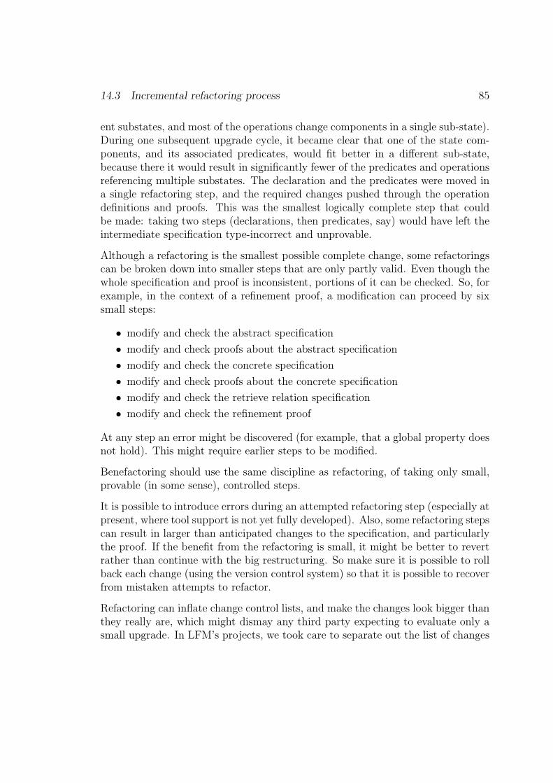
14.3 Incremental refactoring process 85
ent substates, and most of the operations change components in a single sub-state).During one subsequent upgrade cycle, it became clear that one of the state com-ponents, and its associated predicates, would fit better in a different sub-state,because there it would result in significantly fewer of the predicates and operationsreferencing multiple substates. The declaration and the predicates were moved ina single refactoring step, and the required changes pushed through the operationdefinitions and proofs. This was the smallest logically complete step that couldbe made: taking two steps (declarations, then predicates, say) would have left theintermediate specification type-incorrect and unprovable.
Although a refactoring is the smallest possible complete change, some refactoringscan be broken down into smaller steps that are only partly valid. Even though thewhole specification and proof is inconsistent, portions of it can be checked. So, forexample, in the context of a refinement proof, a modification can proceed by sixsmall steps:
• modify and check the abstract specification
• modify and check proofs about the abstract specification
• modify and check the concrete specification
• modify and check proofs about the concrete specification
• modify and check the retrieve relation specification
• modify and check the refinement proof
At any step an error might be discovered (for example, that a global property doesnot hold). This might require earlier steps to be modified.
Benefactoring should use the same discipline as refactoring, of taking only small,provable (in some sense), controlled steps.
It is possible to introduce errors during an attempted refactoring step (especially atpresent, where tool support is not yet fully developed). Also, some refactoring stepscan result in larger than anticipated changes to the specification, and particularlythe proof. If the benefit from the refactoring is small, it might be better to revertrather than continue with the big restructuring. So make sure it is possible to rollback each change (using the version control system) so that it is possible to recoverfrom mistaken attempts to refactor.
Refactoring can inflate change control lists, and make the changes look bigger thanthey really are, which might dismay any third party expecting to evaluate only asmall upgrade. In LFM’s projects, we took care to separate out the list of changes

86 Chapter 14. Refactoring in Z
that were refactorings from those that were real functionality changes, to helpstructure the evaluation task.
14.4 Identifying Z refactorings
The pattern language that we are constructing for Z allows us to capture insights aspatterns; the patterns can then form steps or goals for refactoring. Refactoring op-portunities become more apparent as the specifier gains experience. Additionally,performing proof gives additional insight into the structure of the system.
For example, in the electronic purse project [Stepney et al. 2000], it was noticed thatcertain combinations of state components appeared in the refinement proofs, andthat these combinations mapped to meaningful concepts in the application domain.So these were introduced into the specification as derived state components. Thisrefactoring improved the clarity and structure of both the specification and theproofs.
Lessons learned while doing the proof can be used to refactor the proof itself.For example, in the electronic purse project, a similar property was being provedseveral times. So this property was parameterised, extracted as a proved lemma,then used it several times in the main proof. This shortened and simplified themain proofs. The lemma made sense as a property in the application domain, sothis refactoring also made the proof structure easier to understand.

Chapter 15
Refactoring to Promotion, byexample
15.1 Introduction
This chapter describes refactoring to promotion by use of an example. We startwith an initial specification closely based on the ‘Abstract World’ specificationfrom the LFM electronic purse development[Stepney et al. 2000]. This is a casewhere a specification originally written in a flat Delta/Xi style is then identifiedlater as a candidate complex enough for the promotion elaboration.
The structural promotion pattern is the target pattern for the refactoring, and thegenerative patterns guide the refactoring steps. Some of the refactoring transfor-mations do not seem obvious and might be missed without the generative patternsas a reference. Indeed, some of the transformations temporarily make the specifi-cation structure more baroque.
15.2 Starting point: the existing specification
• purses are identified by a name
[NAME ]
• The abstract world comprises two mappings– balance maps purse names to their balances
– lost maps purse names to the total amount they have lost because offailed transfer operations
87
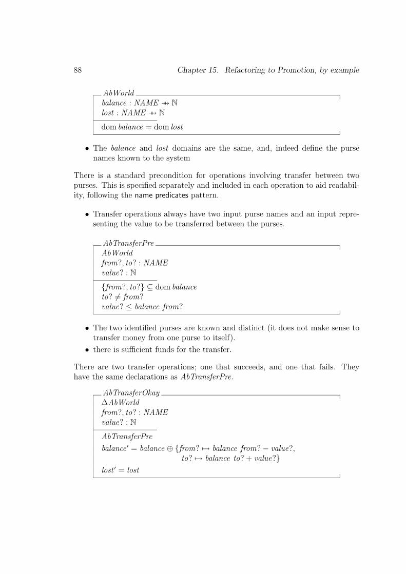
88 Chapter 15. Refactoring to Promotion, by example
AbWorldbalance : NAME 7 7→ N
lost : NAME 7 7→ N
dom balance = dom lost
• The balance and lost domains are the same, and, indeed define the pursenames known to the system
There is a standard precondition for operations involving transfer between twopurses. This is specified separately and included in each operation to aid readabil-ity, following the name predicates pattern.
• Transfer operations always have two input purse names and an input repre-senting the value to be transferred between the purses.
AbTransferPreAbWorldfrom?, to? : NAMEvalue? : N
{from?, to?} ⊆ dom balanceto? 6= from?value? ≤ balance from?
• The two identified purses are known and distinct (it does not make sense totransfer money from one purse to itself).
• there is sufficient funds for the transfer.
There are two transfer operations; one that succeeds, and one that fails. Theyhave the same declarations as AbTransferPre.
AbTransferOkay∆AbWorldfrom?, to? : NAMEvalue? : N
AbTransferPre
balance ′ = balance ⊕ {from? 7→ balance from?− value?,to? 7→ balance to? + value?}
lost ′ = lost
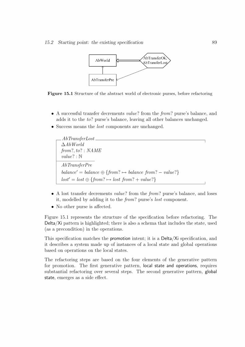
15.2 Starting point: the existing specification 89
Figure 15.1 Structure of the abstract world of electronic purses, before refactoring
• A successful transfer decrements value? from the from? purse’s balance, andadds it to the to? purse’s balance, leaving all other balances unchanged.
• Success means the lost components are unchanged.
AbTransferLost∆AbWorldfrom?, to? : NAMEvalue? : N
AbTransferPre
balance ′ = balance ⊕ {from? 7→ balance from?− value?}lost ′ = lost ⊕ {from? 7→ lost from? + value?}
• A lost transfer decrements value? from the from? purse’s balance, and losesit, modelled by adding it to the from? purse’s lost component.
• No other purse is affected.
Figure 15.1 represents the structure of the specification before refactoring. TheDelta/Xi pattern is highlighted; there is also a schema that includes the state, used(as a precondition) in the operations.
This specification matches the promotion intent; it is a Delta/Xi specification, andit describes a system made up of instances of a local state and global operationsbased on operations on the local states.
The refactoring steps are based on the four elements of the generative patternfor promotion. The first generative pattern, local state and operations, requiressubstantial refactoring over several steps. The second generative pattern, globalstate, emerges as a side effect.

90 Chapter 15. Refactoring to Promotion, by example
15.3 Step 1: introduce local state
The first goal for refactoring is to define the local state. The system describedabove has a collection of purses, so the purse becomes the local instance.
The individual purses each have a balance and a lost component. It is formedby removing the identifying functions and predicates from the original state spec-ification. The result matches the state element of the local state and operationsgenerative pattern element:
AbPursebalance : Nlost : N
The global elements from the original state are refactored to match the global statepattern:
[NAME ]
AbWorldabPurse : NAME 7 7→ AbPurse
The preservation of meaning for abPurse can be established by expanding theschema to a single function from NAME to the tuple (balance, lost). This is equiv-alent to the original state schema, AbWorld .
To complete these refactorings, and to preserve the full sense of the original specifi-cation, the original precondition and operation specifications have to be refactoredto use the local and global states.
• The precondition schema declarations are not affected: purses are still identi-fied by name, even though the name has been relocated to the global context.
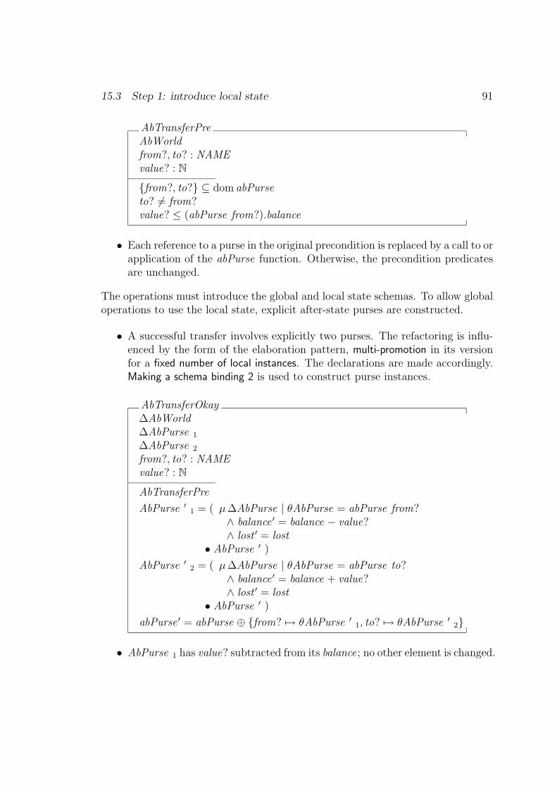
15.3 Step 1: introduce local state 91
AbTransferPreAbWorldfrom?, to? : NAMEvalue? : N
{from?, to?} ⊆ dom abPurseto? 6= from?value? ≤ (abPurse from?).balance
• Each reference to a purse in the original precondition is replaced by a call to orapplication of the abPurse function. Otherwise, the precondition predicatesare unchanged.
The operations must introduce the global and local state schemas. To allow globaloperations to use the local state, explicit after-state purses are constructed.
• A successful transfer involves explicitly two purses. The refactoring is influ-enced by the form of the elaboration pattern, multi-promotion in its versionfor a fixed number of local instances. The declarations are made accordingly.Making a schema binding 2 is used to construct purse instances.
AbTransferOkay∆AbWorld∆AbPurse 1
∆AbPurse 2
from?, to? : NAMEvalue? : N
AbTransferPre
AbPurse ′ 1 = ( µ∆AbPurse | θAbPurse = abPurse from?∧ balance ′ = balance − value?∧ lost ′ = lost
• AbPurse ′ )
AbPurse ′ 2 = ( µ∆AbPurse | θAbPurse = abPurse to?∧ balance ′ = balance + value?∧ lost ′ = lost
• AbPurse ′ )
abPurse ′ = abPurse ⊕ {from? 7→ θAbPurse ′ 1, to? 7→ θAbPurse ′ 2}
• AbPurse 1 has value? subtracted from its balance; no other element is changed.

92 Chapter 15. Refactoring to Promotion, by example
• AbPurse 2 has value? added to its balance; no other element is changed.
• The global world mappings to the instances of the two purses are overwrittenwith the after-states of each purse.
The lost case is refactored similarly.
• An unsuccessful transfer involves exactly one purse. The refactoring is influ-enced by the form of the standard pattern, framing schemas. The declarationsare made accordingly.
AbTransferLost∆AbWorld∆AbPursefrom?, to? : NAMEvalue? : N
AbTransferPre
AbPurse ′ = ( µ∆AbPurse | θAbPurse = abPurse from?∧ balance ′ = balance − value?∧ lost ′ = lost + value?
• AbPurse ′ )
abPurse ′ = abPurse ⊕ {from? 7→ θAbPurse ′}
• AbPurse has value? subtracted from its balance, and added to lost .
• The global world mapping to the purse is overwritten with the purse’s after-state.
This intermediate refactoring preserves the meaning of the original specification,but is otherwise considerably more obscure than the original. Further refactoringis required1.
15.4 Step 2: introduce local operations
Having extracted the local and global states, attention now turns to the extractionof local operations. These are specified to include the local part of the preconditionschema.1 This first refactoring is, in fact, closer to the form of the actual AbPurse specification[Stepneyet al. 2000]. See Appendix A.1 for diagrams of the full specification.
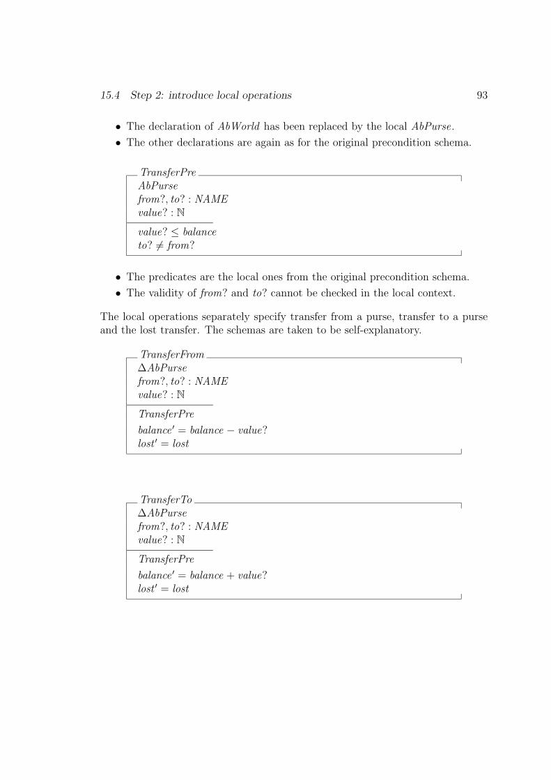
15.4 Step 2: introduce local operations 93
• The declaration of AbWorld has been replaced by the local AbPurse.
• The other declarations are again as for the original precondition schema.
TransferPreAbPursefrom?, to? : NAMEvalue? : N
value? ≤ balanceto? 6= from?
• The predicates are the local ones from the original precondition schema.
• The validity of from? and to? cannot be checked in the local context.
The local operations separately specify transfer from a purse, transfer to a purseand the lost transfer. The schemas are taken to be self-explanatory.
TransferFrom∆AbPursefrom?, to? : NAMEvalue? : N
TransferPre
balance ′ = balance − value?lost ′ = lost
TransferTo∆AbPursefrom?, to? : NAMEvalue? : N
TransferPre
balance ′ = balance + value?lost ′ = lost

94 Chapter 15. Refactoring to Promotion, by example
TransferLost∆AbPursefrom?, to? : NAMEvalue? : N
TransferPre
balance ′ = balance − value?lost ′ = lost + value?
15.5 Step 3: introduce framing schemas
The next generative pattern is framing schemas. Each kind of operation requiresa frame. All the local operations are simple changes to the local state. However,at the global level, a successful transfer updates the state of two purses whilst theunsuccessful transfer updates only one purse.
The validity of the purses involved in a transfer must be checked at the global level,since the name identifiers have only been assigned to the global state. This checkneeds to appear as part of the frame(s).
• The declarations are as for the refactored transfer operation above
ΦTransfer∆AbWorld∆AbPurse 1
∆AbPurse 2
from?, to? : NAMEvalue? : N
{from?, to?} ⊆ dom balancefrom? 6= to?
θAbPurse 1 = abpurse from?θAbPurse 2 = abpurse to?
abPurse ′ = abPurse ⊕ {from? 7→ θAbPurse ′ 1, to? 7→ θAbPurse ′ 2}
• The identities of the two purses are checked against the known identities.

15.6 Step 4: Define the global operations 95
• The abPurse after-state is formed by overriding the mappings for the twoinstances with the results of the local operations.
The single purse TransferLost could be provided with a framing schema, ΦTransferLost ,by an application of the framing schemas pattern:
ΦTransferLost∆AbWorld∆AbPursefrom?, to? : NAMEvalue? : N
{from?, to?} ⊆ dom balancefrom? 6= to?
θAbPurse = abpurse from?
abPurse ′ = abPurse ⊕ {from? 7→ θAbPurse ′}
However, it is equally valid, and requires fewer definitions, to think of the unsuc-cessful global operation as affecting two purses, one of which is unchanged.
15.6 Step 4: Define the global operations
The final step applies the global operations pattern.
AbTransferOkay == ∃∆AbPurse 1; ∆AbPurse 2 •ΦTransfer ∧ TransferFrom 1 ∧ TransferTo 2
AbTransferLost == ∃∆AbPurse 1; ∆AbPurse 2 •ΦTransfer ∧ TransferLost 1 ∧ ΞAbPurse 2
Note: the version using the ΦTransferLost frame is:
AbTransferLost == ∃∆AbPurse • ΦTransferLost ∧ TransferLost
�

96 Chapter 15. Refactoring to Promotion, by example
15.7 Resulting specification, summary
Gathering together all the pieces produced above, the complete specification of theabstract purse world comprises (a) local specifications, (b) framing schema(s) and(c) global transfer operations that promote the local transfer elements.
This could be demonstrated to be strictly equivalent to the original by a schemaexpansion refactoring of both versions, and simplifying. Alternatively, conjectureson the operations could be formulated and proved. Neither is demonstrated here.
Local state : one purse
[NAME ]
AbPursebalance : Nlost : N
TransferPreAbPursefrom?, to? : NAMEvalue? : N
value? ≤ balanceto? 6= from?
TransferFrom∆AbPursefrom?, to? : NAMEvalue? : N
TransferPre
balance ′ = balance − value?lost ′ = lost

15.7 Resulting specification, summary 97
TransferTo∆AbPursefrom?, to? : NAMEvalue? : N
TransferPre
balance ′ = balance + value?lost ′ = lost
TransferLost∆AbPursefrom?, to? : NAMEvalue? : N
TransferPre
balance ′ = balance − value?lost ′ = lost + value?
Global state : world of purses
AbWorldabPurse : NAME 7 7→ AbPurse
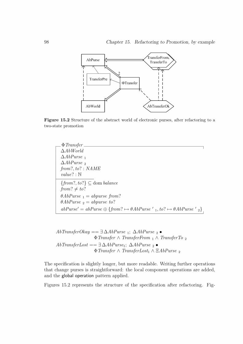
98 Chapter 15. Refactoring to Promotion, by example
Figure 15.2 Structure of the abstract world of electronic purses, after refactoring to atwo-state promotion
ΦTransfer∆AbWorld∆AbPurse 1
∆AbPurse 2
from?, to? : NAMEvalue? : N
{from?, to?} ⊆ dom balancefrom? 6= to?
θAbPurse 1 = abpurse from?θAbPurse 2 = abpurse to?
abPurse ′ = abPurse ⊕ {from? 7→ θAbPurse ′ 1, to? 7→ θAbPurse ′ 2}
AbTransferOkay == ∃∆AbPurse 1; ∆AbPurse 2 •ΦTransfer ∧ TransferFrom 1 ∧ TransferTo 2
AbTransferLost == ∃∆AbPurse1; ∆AbPurse 2 •ΦTransfer ∧ TransferLost1 ∧ ΞAbPurse 2
The specification is slightly longer, but more readable. Writing further operationsthat change purses is straightforward: the local component operations are added,and the global operation pattern applied.
Figures 15.2 represents the structure of the specification after refactoring. Fig-

15.7 Resulting specification, summary 99
Figure 15.3 Structure of AbTransferLost after refactoring using the single local instancepromotion
ure 15.3 shows the alternative form of AbTransferLost , using a separate, single-instance promotion. The diagrams look more complicated than the pre-refactoringdiagram; this demonstrates how much specification structure was implicit before(hidden in the state and operation schemas). The more explicit structure makes aspecification easier to comprehend.

Chapter 16
Refactoring catalogue
16.1 Introduction
In this chapter we describe some of the refactorings that LFM found useful in itsvarious Z projects. Some of these are done simply to improve and clarify structure.Others are done to conform to various Z conventions, as expressed in [Barden etal. 1994], and in the Z patterns described above.
The proofs in these projects were all performed by hand, with minimal tool support(type checking only). The specifications and proofs were independently evaluated;some of the structural improvements are designed to make evaluation of proofseasier. Different refactorings might be more appropriate for tool-supported proofs(discussed below).
Many refactorings can be applied in either direction (since they are meaning pre-serving). In particular, every choice pattern has an associated refactoring, convert-ing between the choices. Which direction to perform the refactoring in a particularcase depends on the specific context.
16.2 Structure of Z refactoring descriptions
The statement of each refactoring has the following structure (some parts may beomitted for brevity)
• Name
• Problem : Short statement of the problem
• Solution : Shorter statement of the solution
100

16.3 Refactoring choice patterns 101
• Discussion : Short statement of the refactoring change, and issues
• Steps : Process to be followed to achieve the refactoring
• Example
• Variants
16.3 Refactoring choice patterns
As we noted earlier, every choice pattern has an associated refactoring, convertingbetween the choices. Some of the explicit refactorings are given here.
Convert a Cartesian Product to a Schema
Problem : You have a Cartesian product type being used as a record, with lotsof component references.
Solution : Introduce a schema product type, and use it instead.
Discussion : This converts from a one use of the choice pattern, modelling prod-uct types : Cartesian product, to the other, modelling product types : schema. Thecomponents of a Cartesian product are labelled by their positions, a not-very mean-ingful number. The components of a schema product are labelled by their names,and these can be chosen to be much more meaningful.
Steps :
• create the new definition, with a new name (if the name of the new andold definitions are to be the same, first do a refactoring to rename the olddefinition)
• typecheck, to ensure there are no name clashes
• change each occurrence of the old name to the new one, and each occurrenceof a component reference from the number to its name (this requires morethan just mechanical changes, see the example)
• typecheck, to ensure the name has been used properly
• propagate the replacement through the proofs
• delete the old definition
• typecheck, to ensure no uses have been missed
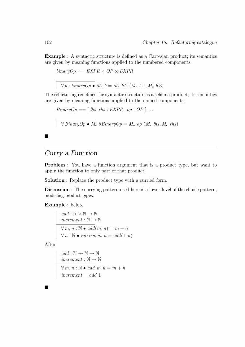
102 Chapter 16. Refactoring catalogue
Example : A syntactic structure is defined as a Cartesian product; its semanticsare given by meaning functions applied to the numbered components.
binaryOp == EXPR ×OP × EXPR
∀ b : binaryOp • Me b = Mo b.2 (Me b.1,Me b.3)
The refactoring redefines the syntactic structure as a schema product; its semanticsare given by meaning functions applied to the named components.
BinaryOp == [ lhs , rhs : EXPR; op : OP ] . . .
∀BinaryOp • Me θBinaryOp = Mo op (Me lhs ,Me rhs)
�
Curry a Function
Problem : You have a function argument that is a product type, but want toapply the function to only part of that product.
Solution : Replace the product type with a curried form.
Discussion : The currying pattern used here is a lower-level of the choice pattern,modelling product types.
Example : before
add : N× N→ N
increment : N→ N
∀m, n : N • add(m, n) = m + n
∀ n : N • increment n = add(1, n)
After
add : N 7→ N→ N
increment : N→ N
∀m, n : N • add m n = m + n
increment = add 1
�

16.4 Other refactorings 103
16.4 Other refactorings
Rename a Component
Problem : You have a specification component with a name that does not indicateits purpose, or otherwise does not name consistently
Solution : Change the name.
Discussion : This refactoring is most useful in the early stages of specification.Initial names choices can become inappropriate as the specification develops andthe purpose of a component is clarified. The refactoring may even be a responseto the overmeaningful name antipattern, in which the initial name contains more“semantics” than its definition. The naming convention is often evolving at thispoint: name consistently may be applied only once the naming conventions havestabilised.
Steps :
• choose the new name
• update the naming convention documentation if necessary
• rename in the definition, and any indexes that refer to it
• propagate the name change throughout the specification and proofs.
A typechecker can help to find all the places the name needs to be changed.
�
Extract Commonality
Problem : You have a term, predicate or chunk that is used in several places inthe specification or proof.
Solution : Introduce a new definition to name meaningful chunks or name predi-cates, and use that name in place of the term.
Discussion : Make sure the newly named term is a meaningful concept in itsown right, not just derived from a textual coincidence. Let the name capture thismeaning (and follow any naming convention pattern in use). The use of the name

104 Chapter 16. Refactoring catalogue
makes the specification more readable, and more concise.
The new name might be introduced as a global definition (possibly an entry ina domain specific toolkit), a schema, a derived state component, a local definition(existentially quantified), or a lemma (in which case the “name” occurs in theinformal commentary rather than the formal text).
Steps :
• create the new definition
• typecheck, to ensure there are no name clashes
• for each use of the term in the scope of the definition– replace the use of the term with the name
– typecheck, to ensure the name has been used properly in this case
– propagate the replacement through the proofs (this may require the addi-tion of an expansion step, replacing the name with its definition, at eachpoint in the proof when the definition is used)
Variants : A special case of this refactoring is Genericise Common Definitions,used where several similar definitions acting on different types. The solution is todefine a generic construct that captures all the behaviours. This uses generics tocontrol detail.
�
Inline a Name
Problem : You have a name with a relatively simple definition, used only once ora few times.
Solution : Remove the name, and replace its use(s) with its definition.
Discussion : This is essentially the Extract Commonality refactoring in reverse.Getting the right size of chunking is an art. Too few names and the reader has topuzzle out large swathes of mathematics. Too many names, and the reader has toremember their meaning when puzzling out their uses.
Steps :
• for each use of the name– replace the name with its definition
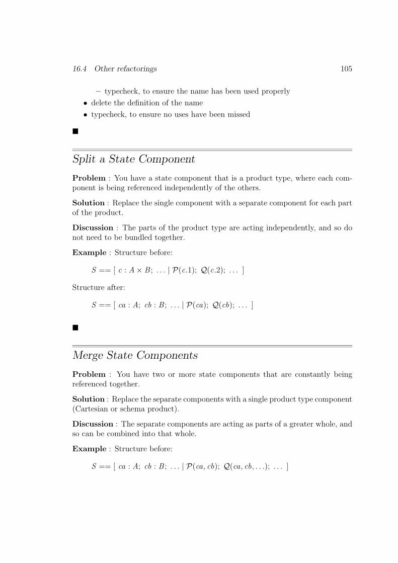
16.4 Other refactorings 105
– typecheck, to ensure the name has been used properly
• delete the definition of the name
• typecheck, to ensure no uses have been missed
�
Split a State Component
Problem : You have a state component that is a product type, where each com-ponent is being referenced independently of the others.
Solution : Replace the single component with a separate component for each partof the product.
Discussion : The parts of the product type are acting independently, and so donot need to be bundled together.
Example : Structure before:
S == [ c : A× B ; . . . | P(c.1); Q(c.2); . . . ]
Structure after:
S == [ ca : A; cb : B ; . . . | P(ca); Q(cb); . . . ]
�
Merge State Components
Problem : You have two or more state components that are constantly beingreferenced together.
Solution : Replace the separate components with a single product type component(Cartesian or schema product).
Discussion : The separate components are acting as parts of a greater whole, andso can be combined into that whole.
Example : Structure before:
S == [ ca : A; cb : B ; . . . | P(ca, cb); Q(ca, cb, . . .); . . . ]
106 Chapter 16. Refactoring catalogue
Structure after (Cartesian product):
S == [ c : A× B ; . . . | P(c); Q(c, . . .); . . . ]
Structure after (schema product):
C == [ ca : A; cb : B ]
S == [ c : C ; . . . | P(c); Q(c, . . .); . . . ]
If some of the predicate part can also be bundled, alternative structure after (Carte-sian product):
C == { ca : A; cb : B | P(ca, cb) }S == [ c : C ; . . . | Q(c, . . .); . . . ]
Alternative structure after (schema product):
C == [ ca : A; cb : B ; . . . | P(ca, cb) ]
S == [ c : C ; . . . | Q(c, . . .); . . . ]
�
Split a State into Substates
Problem : You have a large number of state components.
Solution : Structure the state into substates.
Discussion : This applies the name meaningful chunks and assemble from chunkspatterns. Smaller chunks of state may be easier to understand, and may simplifyoperation definitions. Components that constrain each other, and componentsthat change together, are candidates for being in the same substate. Most statepredicates are on substates, with few on the global state. Also most operationsaffect only a single substate, and the unchanging nature of the other substates canbe captured with a few Ξ schemas, rather than a long list of unchanging statecomponents (see Delta/Xi : change part of the state).
This refactoring may be followed by expand schemas slowly refactoring, to takeadvantage of the opportunity to expand only the relevant substates (this may resultin some extra steps being added, as the substates are expanded one by one).
Steps :

16.4 Other refactorings 107
• define substate schemas; typecheck
• modify the state schema to use these; typecheck
• modify each operation schema to use these, including the use of ∆ and Ξsubstate schemas; typecheck
• define substate initialisation operations; typecheck
• use schema calculus to define the state initialisation operation using the sub-state initialisations; typecheck
• propagate through the proofs
Example : before
S == [ x , y : Z; a, b : PZ | x ∈ a; y 6∈ b; a 6= b ]
Op == [ ∆S ; x? : Z | x ′ = x?; a ′ = a ∪ {x?}; y ′ = y ; b ′ = b ]
InitS == [ S ′ | x ′ = 0; y ′ = 1; a ′ = {x ′}; b ′ = ∅ ]
After
Sx == [ x : Z; a : PZ | x ∈ a ]
Sy == [ y : Z; b : PZ | y 6∈ b ]
S == [ Sx ; Sy | a 6= b ]
Op == [ ∆Sx ; ΞSy ; x? : Z | x ′ = x?; a ′ = a ∪ {x?} ]
InitSx == [ Sx ′ | x ′ = 0; a ′ = {x ′} ]
InitSy == [ Sy ′ | y ′ = 1; b ′ = ∅ ]
InitS == InitSx ∧ InitSy . . .
�
Move a State Component between Substates
Problem : You have a substate component frequently being used along withcomponents in another substate.
Solution : Move the component and any predicates into the other substate. Thisnormally has to be done as one step, since the specification is likely to inconsistentduring the move. The specification is only typechecked after the whole move.
�
108 Chapter 16. Refactoring catalogue
Split an Operation into Disjuncts
Problem : You have an operation with a top level disjunct amongst its predicates.
Solution : Split the operation into two parts, one for each disjunct.
Example : before
Op == [ ∆S | P; Q ∨ R; S ]
After
OpQ == [ ∆S | P; Q; S ]
OpR == [ ∆S | P; R; S ]
Op == OpQ ∨ OpR
�
Split an Operation into a Composition
Problem : You have an operation with some existentially quantified state com-ponents that are acting as “intermediate” variables.
Solution : Split the operation into two on these components, and compose theparts.
Discussion : This is effectively expanding out the definition of schema composi-tion1.
Example : before
Op == [ ∆S | ∃ S 0 • P(θ S , θ S 0) ∧ Q(θ S 0, θ S ′) ]
After
Op1 == [ ∆S | P(θ S , θ S ′) ]
Op2 == [ ∆S | Q(θ S , θ S ′) ]
Op == Op1 o9 Op2
1 This suggests there should be a similar refactoring for schema piping. However, since we haveyet to come across a realistic case of piping in a large specification, we leave out the description.
16.4 Other refactorings 109
�
Reorder Product Arguments
Problem : You have two functions, one with a product range, one with a productdomain, that you want to compose, but the products have their items in differentorders.
Solution : Reorder one of the products to match the other.
Example : before
f : X 7→ Y × Zg : Z × Y 7→Wh : X 7→W
∀ x : X • ∃ y : Y ; z : Z | (y , z ) = f x • h x = g(z , y)
After:
f : X 7→ Y × Zg : Y × Z 7→Wh : X 7→W
h = f o9 g
�
Reorder Curried Arguments
Problem : You have a function that you want to partially apply, but the argumentorder does not support that.
Solution : Reorder the arguments so that it can be partially applied.
Example : before
f : X 7→ Y 7→ Zg : X 7→ Z
∃ y : Y • ∀ x : X • f x y = g x
After

110 Chapter 16. Refactoring catalogue
f : Y 7→ X 7→ Zg : X 7→ Z
∃ y : Y • f y = g
�
Thin Early, Thin Often
Problem : You have a large, clumsy hypothesis in a goal you are trying to prove.
Solution : Thin the hypothesis as early and as often as is possible.
Discussion : Thinning declarations and predicates from the hypothesis has twoadvantages: it keeps the hypothesis small and manageable; and it indicates moreclearly what remaining properties are still required to discharge the goal.
�
Move a Common Proof Step Before a Branch Point
Problem : You have a proof that has branched into several “cases” (for example,when splitting up a disjunct in the hypothesis), and a similar step is used in eachbranch (for example, cutting in a particular value).
Solution : Move the step before the case split, and do it only once.
Discussion : If the step is only “similar” in each branch, it is first necessaryto apply some other refactorings to make the step the same in each branch (forexample, by parameterising the proof on the case branch parameter) before thisrefactoring can be performed.
�
Turn a Common Proof Step into a Lemma
Problem : You have a chunk of proof that is used in several places.
Solution : Extract the commonality as a lemma.

16.4 Other refactorings 111
Discussion : This is a special case of extract commonality . Make sure the lemmais meaningful in isolation, and is not just a “textual macro”.
�
Schema expansion
Problem: You need to manipulate the internals of a schema, or schema expression.
Solution: Expand the schema.
Discussion: Sometimes it is necessary to present a schema in an expanded orfully normalised form, to understand the internals, or to negate a schema, or tocalculate a precondition, for example. This refactoring should make use of theExpand schemas slowly refactoring.
Steps:
• Expand the schema calculus operators, using their definitions.
• Expand schema components, by inlining included schemas.
• Expand toolkit definitions in declarations, and move the constraints to thepredicate part, leaving only type information.
�
Expand schemas slowly
Problem : You have a large or deeply nested schema that is being expanded, orflattened, in a single step, resulting in the sudden appearance of a lot of (as yet)unnecessary terms.
Solution : Expand the schema incrementally, exposing only those terms neededat any given stage.
Discussion : This may require the prior use of the split a state into substates or thesplit an operation into disjuncts refactoring, to provide parts that can be expandedseparately.
If the schema is used as a predicate in the goal’s hypothesis, consider duplicatingthe required term outside the schema, rather than expanding the schema. Use theterm as required, then thin it.

112 Chapter 16. Refactoring catalogue
�
16.5 Refactoring as a proof technique
The concept of refactoring can be used when performing a (hand) proof. A proofcan be considered to be the documentation of a sequence of meaning preservingtransformations of a goal that improves its structure in a particular way, to thepredicate true.
Many proof steps can be applied in either a forward or backward manner, andhence are meaning preserving. Examples include one-pointing or applying Leibniz(replacing equals by equals), schema expansions, and various eliminations. Suchsteps can be treated as refactorings. The presentation of the proof can be con-structed by repeating the following steps:
• copy and paste the most recent form of the goal
• perform the desired refactoring by suitably editing the copy
• typecheck
For brevity of presentation, several refactorings (such as several one-pointings) maybe performed on a single copy of the goal. However, to make such a presentationstep comprehensible to reviewers, no single part of the goal changed by a refactoringshould be further changed by a subsequent refactoring in the same step (that is,restrict multiple refactorings to distinct parts of the goal).
The names of the refactorings performed form part of the documentation of theproof step.

Chapter 17
Benefactorings
Some benefactorings used in LFM projects are noted here.
Change a Type
Problem : A functionality change requires a component’s type to be changed.For example, a simple type might need to be extended to a product type.
Solution : Before adding any new functionality, make the minimal change to thetype (so, add the new component throughout, but don’t use it yet).
Steps :
• modify the type in the abstract model; typecheck
• modify any global property proofs about the abstract model
• modify the type in the concrete model; typecheck
• modify any global property proofs about the concrete model
• modify the retrieve relation that links the modified types if appropriate; type-check
• modify the refinement proof as necessary
�
Add a State Component
Problem : A functionality change requires a new state component.
Solution : Add the component, and perform the knock-on changes, withoutadding any extra functionality based on the component.
113
114 Chapter 17. Benefactorings
Discussion : This is the change a type refactoring applied in a slightly largercontext to adding a state component to a Delta/Xi specification, in order to addmore functionality.
Steps :
• add the component to the abstract model; typecheck
• add abstract constraints; typecheck
• modify any global property proofs about the abstract model
• add the component to the concrete model; typecheck
• add concrete constraints; typecheck
• modify any global property proofs about the concrete model
• modify the retrieve relation to link the new abstract and concrete compo-nents; typecheck
• modify the refinement proof as necessary
�
Add an Operation
Problem : A functionality change requires a new operation.
Solution : Add the operation, and perform the knock-on changes.
Discussion : When following the Delta/Xi pattern, adding an operation has littleeffect on the specification. If the model has theorems about global properties, it isnecessary to modify their proofs to ensure the properties still hold.
Variant : Steps for promotion
• add the new local operation; typecheck
• add a new framing schema, if necessary
• add the new global operation; typecheck
• modify any global property proofs about the model
Variant : Steps for refinement
• add the operation to the abstract model; typecheck
• modify any global property proofs about the abstract model

115
• add the operation to the concrete model; typecheck
• modify any global property proofs about the concrete model
• add a new branch to the refinement proof to cover the new operation
�
Add a Function Argument
Problem : A functionality change a new argument to a function.
Solution : First add the argument, then add the constraints separately.
�

116 Chapter 17. Benefactorings

Part III
Wrapping up

Chapter 18
Tool support
18.1 Introduction
The use of (generative sets of) patterns to produce Z specifications and to refactorexisting specifications goes some way towards facilitating the use of Z – particularlyin conjunction with existing Z tools.
However, commercial specification developers need more, and better-targetted,tools. The required tools should both exploit and support patterns and refac-toring:
• Where a pattern or some part of it is fixed-form, a tool should support itdirectly (perhaps as a built-in generic instantiated by the user).
• Where a pattern provides a template, or where various forms apply in differentcontexts, the tool should guide the user.
• New Z tools should aim to support documentation formats, presentationpatterns and alternation between well-defined choice patterns.
• Existing Z tools might be refactored to exploit similar patterns directly.
18.2 Existing Tool Support
Tool support for patterns is an important requirement for the (industrial) specifi-cation development process. Manual application of patterns during development isdifficult – even simple things like name consistently can be overlooked, especially ifthe naming convention is evolving with the specification. Conforming to patternsduring maintenance is even more difficult, especially if the particular patterns usedhave not been documented.
119

120 Chapter 18. Tool support
In the object-oriented community, there is work on integrating patterns into thedevelopment process. Some schemes have been invented for encoding patterns inclasses, but the match is not good. Patterns are at a different level from the lan-guage constructs. Mostly, naming conventions and comments are used to indicatethe presence or use of patterns in the code. But some tool support is possible, bothin software development and in formal notations. Rather than try to invent a newgeneral purpose meta-language to support the identified patterns, tool developersshould first concentrate on supporting the individual patterns explicitly.
Current Z tools are mostly syntax- and type-checkers, and proof tools. Comparedto programming language IDEs, they provide relatively unsophisticated develop-ment environments.
The presentation patterns are supported to a greater or lesser extent by currentZ tools, but even there little is automatic. Existing tools format to expose struc-ture: most LATEX-based tools, for example, [Spivey 1992a], give the user completecontrol over line breaks, indentation and white space within phrases; other toolssuch as CADiZ [Toyn 2001] and Formaliser [Stepney 2001] have automatic ‘pretty-printing’ layouts, but they do not always give optimal readability, and are notconfigurable to different layout standards. Similarly, provide navigation is sup-ported in LATEX-based tools via the LATEX \index command and in HTML-basedtools via hyperlinks. Z-Eves [Saaltink 1997] has a good navigation interface. Nameconsistently is partially supported by search and replace; such operations are evenmore useful when scope-sensitive. Graphical tools for GUI design show how a toolcan automatically generate underlying code such that user changes to that codeare reflected back in the GUI design. A similar approach could be used to supportmany of the Z patterns.
Z development process patterns are, surprisingly, the best supported, because manyof the identified patterns are validation patterns requiring proof, for which prooftools exist. But even proof tools provide little explicit support for validation proofpatterns – they are general purpose, rather than sensitive to the particular proofsrequired. There is some support for animation, ranging from conventions for semi-automatic translation of Z to an executable form [West & Eaglestone 1992], [Hewittet al. 1997], to executable subsets of Z itself [Valentine 1992]. Making such con-ventions and tools sensitive to particular structural patterns would greatly smooththe process.
Z tools implement various patterns and refactorings. Tools such as CADiZ pro-vide sanity checks such as precondition calculation, schema expansion, and otherrewritings that preserve the mathematical semantics of the Z specification. The

18.3 A better way of supporting patterns 121
current motivation for these refactorings is the need to provide normalised speci-fication components for mechanised proof assistance. The profile of the softwareengineering motivations needs to be raised!
18.3 A better way of supporting patterns
Template support for presentation patterns such as comment the intention couldbe provided: addition of a declaration or predicate would cause a new commentline to be provided, with a prompt to the developer to explain the addition (eitheron the comment line or in an existing comment line). The tool should managethe linking of comment lines to the Z lines; reordering of declaration or predicatesshould cause corresponding reordering of their associated comments.
Tool support for choice patterns would allow users to change their minds. As atrivial example, Formaliser can convert between a horizontal and vertical schemadisplay. Support for modelling product types, to assist in changing the representa-tion between schemas and Cartesian products, could be implemented by adaptationfrom existing tool support for schema expansion.
Architecture patterns are not yet well supported by tools. Delta/Xi is supported,simply because its naming conventions are partly encoded in the Z core language,yet tools need to ‘understand’ whether a particular schema is a state, an operation,or a piece of scaffolding.
Interactive support in the form of state and operation templates, framing schematemplates for promotion, and function definitions broken down over free types formorph, could all be automated. The Delta/Xi diagrams presented above show theschema components and their interrelationships; these could form a framework for“intelligent” architectural support, extending the existing tool facilities for trackingnamed component usage in a specification.
One day, tools may be configurable to support different specification aims (read-ability, provability, etc). They may be able to detect antipatterns in each style ofspecification, and able to guide the developer to a better representation, based onthe patterns appropriate to that form of specification.

122 Chapter 18. Tool support
18.4 Tool support for refactoring
A code refactoring can affect an entire program. For example, changing the nameof a method involves a change at every place that method is called. However,although widespread, such a change is shallow. Deeper code refactorings tend tobe confined to small regions of code. It is by having small changes (either small indepth, or small in breadth) that code refactoring is manageable.
Formal specification and proof refactorings tend to have more widespread effects,because of the impact of a specification change on the proofs and later developmentsteps. For example, adding a component or predicate to the state may involveadding it to the proof of every operation. Again, the changes tend to be shallow:the addition will probably have little or no effect on most operations. However,every proof needs to be checked, and this can be tedious without suitable toolsupport.
Tools are currently being built to support code refactorings. For example, thelatest version of JBuilder includes a refactoring wizard; the Demeter tool (North-eastern University, Boston, US) supports generic Java programming, and a rangeof refactoring and reuse facilities [Demeter Research Group 1999]. Similar toolsupport (within a proof tool) for formal refactoring would be a benefit. Such atool could support common refactorings such as those described earlier
Also important is support for pushing a relatively small change through the proof.This requires facilities for parameterising tactics for machine-generated proofs.This is a matter of on-going research.

Chapter 19
Conclusion
Z patterns have something in common with many of the software engineering pat-tern languages.
• [Beck 1997]’s Smalltalk coding standards provide inspiration for commentingand presentations
• [Gamma et al. 1995]’s design patterns are similar in intent to many of thepresentation and structural Z patterns
• [Larman 2001]’s UML patterns can be compared to the higher-level architec-ture patterns, and the generative use of patterns
A Pattern Language for Z, which is essentially a packaging of existing languageelements and usage according to their context of use, will help to make explicit thewider range of conventions and styles available. In addition, it will help to providegood solutions to well-known recurrent problems.
Refactoring is a natural partner of patterns. The patterns provide refactoringtargets, and alert developers to potential refactorings. Everyone refactors, as un-derstanding of the system being described or experience of the description languageevolves. The trick is to do refactoring in a controlled, reversible manner. This re-quires tool support, for the modelling language, and for the development processwhich is the context for the use of the language. It also requires a good under-standing of,
• the purpose of the model (communication, proof, or whatever)
• the required form of meaning preservation, so that the legitimacy of therefactoring can be demonstrated.
123

Appendix A
Diagram illustrations
A.1 Delta/Xi pattern diagrams
This section illustrates the use of Delta/Xi : diagram the structure on a large real-world specification, that of the electronic Purse in [Stepney et al. 2000].
It makes use of several features:
• dotted boxes for items not occurring explicitly in the specification
• indicating multiple similar schemas with overlapping boxes (and a namingconvention)
• splitting the diagram into three, and using rounded boxes to indicate overlap
• highlighting the use of the promotion pattern (shaded boxes)
A.2 Morph pattern diagrams
This section illustrates the use of Morph : diagram the structure on a medium-sizedexample specification, that of the toy compiler in [Stepney 1993], and on a largereal-world specification, that of the real compiler in [Stepney & Nabney 2003].
124

A.2 Morph pattern diagrams 125
Figure A.1 Diagram of the structure of the abstract Purse model [Stepney et al. 2000,chapter 3].

126 Chapter A. Diagram illustrations
Figure A.2 Diagram of the structure of the concrete Purse model, local state [Stepneyet al. 2000, chapter 4].
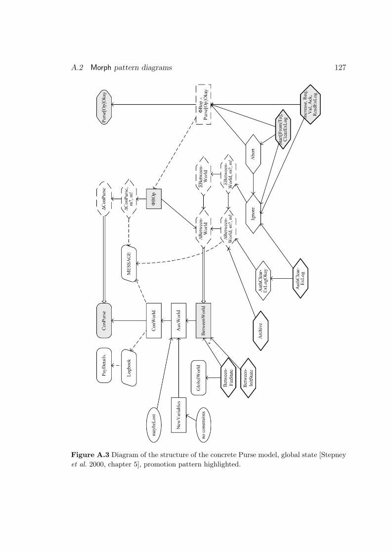
A.2 Morph pattern diagrams 127
Figure A.3 Diagram of the structure of the concrete Purse model, global state [Stepneyet al. 2000, chapter 5], promotion pattern highlighted.

128 Chapter A. Diagram illustrations
Figure A.4 Diagram of the structure of the Tosca command compile function, appliedto the choice command [Stepney 1993, section 11.4.5].
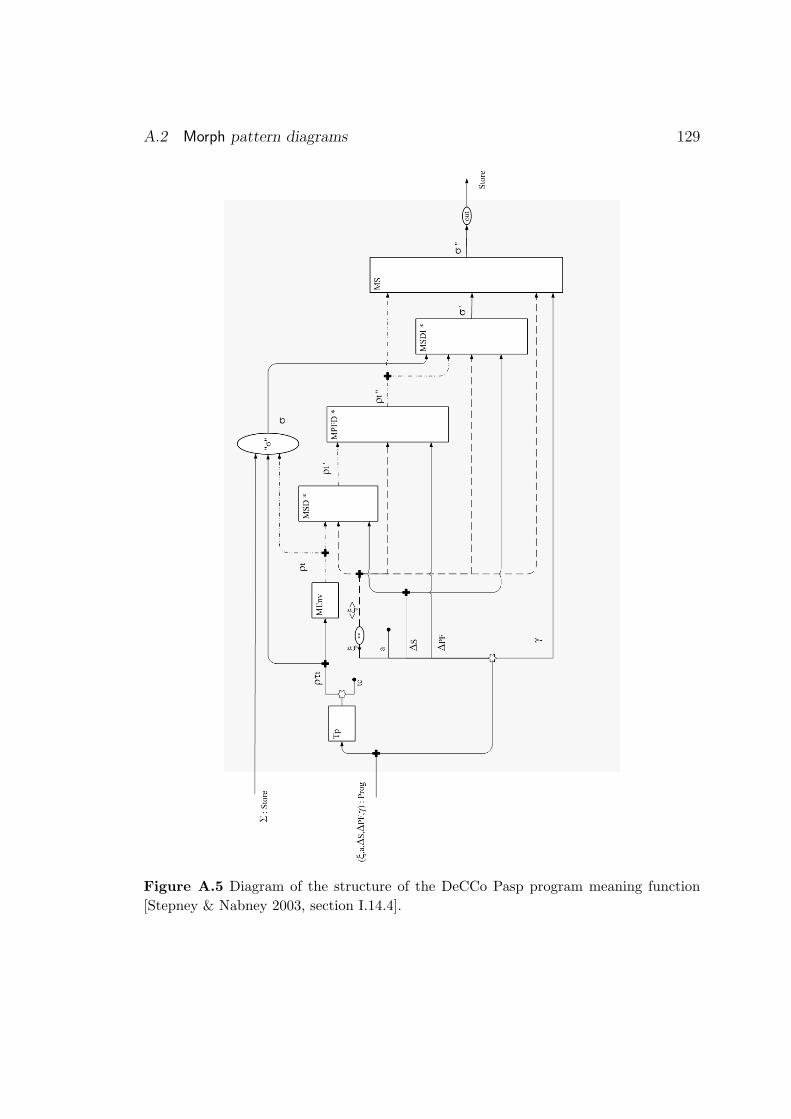
A.2 Morph pattern diagrams 129
Figure A.5 Diagram of the structure of the DeCCo Pasp program meaning function[Stepney & Nabney 2003, section I.14.4].

Appendix B
Bibliography
[Alexander et al. 1977]Christopher Alexander, Sara Ishikawa, Murray Silverstein, Max Jacobson,Ingrid Fiksdahl-King, and Shlomo Angel. A Pattern Language: Towns,Buildings, Construction. Oxford University Press, 1977.
[Arthan 2000]Rob Arthan. Analysis of compiled code: a prototype formal model. In[Bowen et al. 2000], pages 433–449.
[Barden et al. 1994]Rosalind Barden, Susan Stepney, and David Cooper. Z in Practice. BCSPractitioners Series. Prentice Hall, 1994.
[Basin et al. 2002]D. Basin, R. Rittinger, and L. Vigano. Analysis of the CORBA securityservice. In [Bert et al. 2002].
[Beck 1997]Kent Beck. Smalltalk Best Practice Patterns. Prentice Hall, 1997.
[Bert et al. 2002]Didier Bert, Jonathan P. Bowen, Martin C. Henson, and Ken Robinson, ed-itors. ZB2002: Second International Conference of B and Z Users, Greno-ble, January 2002, volume 2272 of LNCS. Springer Verlag, 2002.
[Bowen et al. 2000]Jonathan P. Bowen, Steve Dunne, Andy Galloway, and Steve King, editors.ZB2000: First International Conference of B and Z Users, York, August2000, volume 1878 of LNCS. Springer Verlag, 2000.
[Brown et al. 1998]
130

131
William J. Brown, Raphael C. Malveau, Hays W. McCormick III, andThomas J. Mowbray. AntiPatterns. Wiley, 1998.
[Brown 1979]Peter J. Brown. Writing Interactive Compilers and Interpreters. Wiley,1979.
[Cooper & Stepney 2000]David Cooper and Susan Stepney. Segregation with communication. In[Bowen et al. 2000], pages 451–470.
[Coplien 1995]James O. Coplien. A generative development-process pattern language. InJames O. Coplien and Douglas C. Schmidt, editors, Pattern Languages ofProgram Design. Addison-Wesley, 1995.
[Demeter Research Group 1999]Demeter Research Group. DJ web pages.http://www.ccs.neu.edu/research/demeter/DJ/DJ-product-guide.html, 1999.
[d’Inverno & Luck 2001]Mark d’Inverno and Michael Luck. Understanding Agent Systems. SpringerVerlag, 2001.
[d’Inverno & Priestly 1995]Mark d’Inverno and M. Priestly. Structuring specification in Z to build aunifying framework for hypertext systems. In Ninth International Confer-ence of Z Users, Limerick, Ireland, September 1995, volume 967 of LNCS,pages 83–102. Springer Verlag, 1995.
[Duke & Rose 2000]Roger Duke and Gordon Rose. Formal Object-Oriented Specification UsingObject-Z. Macmillan, 2000.
[Dyer 1992]M. Dyer. The Cleanroom Approach to Quality Software Development. Wi-ley, 1992.
[Easterbrook et al. 1996]S. Easterbrook, R. Lutz, J. Covington, J. Kelly, M. Ampo, and D. Hamil-ton. Experiences using formal methods for requirement modeling.NASA/WVU Software Research Lab, Fairmont, WV, Technical ReportNASA-IVV-96-018, 1996.
132 Chapter B. Bibliography
[Flinn & Sørensen 1992]Bill Flinn and Ib Holm Sørensen. Specification of the UNIX filing system.In [Hayes 1992].
[Fowler 1997]Martin Fowler. Analysis Patterns. Addison-Wesley, 1997.
[Fowler 1999]Martin Fowler. Refactoring: improving the design of existing code. Addison-Wesley, 1999.
[France 2001]Robert France, 2001. private communication.
[Gamma et al. 1995]Erich Gamma, Richard Helm, Ralph Johnson, and John Vlissides. DesignPatterns. Addison-Wesley, 1995.
[Goguen & Malcolm 1996]Joseph Goguen and Grant Malcolm. Algebraic Semantics of ImperativePrograms. MIT Press, 1996.
[Hall 1990]J. Anthony Hall. Using Z as a specification calculus for object-orientedsystems. In Dines Bjorner, C. A. R. Hoare, and H. Langmaack, editors,VDM’90: VDM and Z – Formal Methods in Software Development, Kiel,volume 428 of LNCS, pages 290–318. Springer Verlag, 1990.
[Hayes 1992]Ian Hayes, editor. Specification Case Studies. Prentice Hall, second edition,1992.
[Heisel & Souquieres 1999]Maritta Heisel and Jeanine Souquieres. A method for requirements elic-itation and formal specification. Industrial tutorial presented at FM’99:World Congress on Formal Methods, Toulouse, 1999.
[Hewitt et al. 1997]M. A. Hewitt, C. M. O’Halloran, and C. T. Sennett. Experiences withPiZA, an animator for Z. In J. P. Bowen, M. G. Hinchey, and D. Till,editors, ZUM’97: The Z Formal Specification Notation, volume 1212 ofLNCS, pages 37–51. Springer-Verlag, 1997.
133
[Hoare 1985]C. A. R. Hoare. Communicating Sequential Processes. Prentice Hall, 1985.
[ISO-Z 2002]ISO/IEC 13568. Information Technology—Z Formal SpecificationNotation—Syntax, Type System and Semantics: International Standard,2002.
[Larman 2001]Craig Larman. Applying UML and Patterns, 2nd edition. Prentice Hall,2001.
[Lopes & Lieberherr 1994]Cristina Videira Lopes and Karl Lieberherr. Generative patterns. InECOOP’94 Workshop on Patterns, Bologna, Italy, 1994.
[Mander & Polack 1995]Keith C. Mander and Fiona Polack. Rigorous specification using structuredsystems analysis and Z. Information and Software Technology, 37(5):285–291, 1995.
[Matthews & Swatman 2000]Chris Matthews and Paul A. Swatman. Fuzzy concepts and formal meth-ods: A fuzzy logic toolkit for Z. In [Bowen et al. 2000], pages 491–510.
[Morgan & Suffrin 1992]Carroll Morgan and Bernard Suffrin. Specification of the UNIX filing sys-tem. In [Hayes 1992].
[Polack & Stepney 1999]Fiona Polack and Susan Stepney. System development using Z generics. InFM99, Toulouse, France, volume 1708 and 1709 of LNCS, pages 1048–1067.Springer Verlag, 1999.
[Polack et al. 1993]Fiona Polack, Mark Whiston, and Keith C. Mander. The SAZ project: Integrating SSADM and Z. In FME’93 : Industrial Strength FormalMethods, Odense, Denmark, volume 670 of LNCS, pages 541–557. SpringerVerlag, April 1993.
[Saaltink 1997]Mark Saaltink. The Z/EVES system. In ZUM’97: The Z Formal Specifi-cation Notation, LNCS 1212. Springer, 1997.
134 Chapter B. Bibliography
[Semmens et al. 1992]L. T. Semmens, R. B. France, and T. W. Docker. Integrated structuredanalysis and formal specification techniques. The Computer Journal, 35(6),1992.
[Smith 2000]Graeme Smith. The Object-Z Specification Language. Kluwer, 2000.
[Spivey 1992a]J. Michael Spivey. The fuzz Manual. The Spivey Partnership, 2nd edition,1992. ftp://ftp.comlab.ox.ac.uk/pub/Zforum/fuzz.
[Spivey 1992b]J. Michael Spivey. The Z Notation: a Reference Manual. Prentice Hall,2nd edition, 1992.
[Stepney & Cooper 2000]Susan Stepney and David Cooper. Formal methods for industrial products.In [Bowen et al. 2000], pages 374–393.
[Stepney & Cooper 2003]Susan Stepney and David Cooper. Smart card operating system: Spec-ification, refinement, and proof. Technical Report YCS-2002-???, York,2003.
[Stepney & Nabney 2003]Susan Stepney and Ian Nabney. The DeCCo papers. Technical ReportYCS-2003-???, York, 2003.
[Stepney et al. 1992]Susan Stepney, Rosalind Barden, and David Cooper, editors. Object Ori-entation in Z. Springer Verlag, 1992.
[Stepney et al. 2000]Susan Stepney, David Cooper, and Jim Woodcock. An electronic purse:Specification, refinement, and proof. Technical Monograph PRG-126,Programming Research Group, Oxford University Computing Laboratory,2000.
[Stepney 1993]Susan Stepney. High Integrity Compilation: A Case Study. Prentice Hall,1993.

135
[Stepney 1998]Susan Stepney. A tale of two proofs. In BCS-FACS Third Northern FormalMethods Workshop, 1998.
[Stepney 2001]Susan Stepney. Formaliser Home Page.http://public.logica.com/˜formaliser/, 2001.
[Toyn 2001]Ian Toyn. CADiZ web pages.http://www-users.cs.york.ac.uk/˜ian/cadiz/, 2001.
[Valentine et al. 2000]Samuel H. Valentine, Ian Toyn, Susan Stepney, and Steve King. Type-constrained generics for Z. In [Bowen et al. 2000], pages 250–263.
[Valentine 1992]Samuel H. Valentine. Z−−, an executable subset of Z. In J. E. Nicholls,editor, Z User Workshop, York 1991, Workshops in Computing, pages 157–187. Springer-Verlag, 1992.
[Valentine 1993]Samuel H. Valentine. Putting numbers into the mathematical toolkit. InJonathan P. Bowen and John E. Nicholls, editors, Proceedings of the 7thAnnual Z User Meeting, London 1992, Workshops in Computing. SpringerVerlag, 1993.
[West & Eaglestone 1992]M. M. West and B. M. Eaglestone. Software development: Two approachesto animation of Z specifications using Prolog. IEE/BCS Software Engineer-ing Journal, 7(4):264–276, July 1992.
[Woodcock & Cavalcanti 2002]J. C. P. Woodcock and A. L. C. Cavalcanti. The semantics of circus. In[Bert et al. 2002].
[Woodcock & Davies 1996]J. C. P. Woodcock and J. Davies. Using Z. Specification, Refinement, andProof. Prentice–Hall, 1996.
[Woodcock & Loomes 1988]Jim Woodcock and Martin Loomes. Software Engineering Mathematics.Pitman, 1988.

136 Chapter B. Bibliography
[Wordsworth 1987]J. B. Wordsworth. Formal methods in the development of CICS. BCSComputer Bulletin, December 1987.