a0005 1.12 carbon nanotube membranes: a new frontier … · although molecular dynamic (md)...
TRANSCRIPT

ELS
EVIE
RAU
THO
RPR
OO
F
1.12a0005 Carbon Nanotube Membranes: A New Frontier inMembrane ScienceM Majumder and P M Ajayan, Rice University, Houston, TX, USA
ª 2010 Elsevier B.V. All rights reserved.
1.12.1 Introduction 1
1.12.2 CNT Membranes 2
1.12.2.1 Template-Synthesized CNT Membrane 2
1.12.2.2 Dense-Array Outer-Wall CNT Membrane 4
1.12.2.3 Open-Ended CNT Membrane 5
1.12.2.4 Mixed-Matrix CNT Membranes 6
1.12.3 Properties and Application of CNT Membranes 6
1.12.3.1 Functionalization of CNT Membranes 7
1.12.3.2 CNT Membranes for Gas/Vapor Transport Applications 7
1.12.3.3 CNT Membranes for Stimuli-Responsive Applications 9
1.12.3.4 CNT Membrane in Liquid Transport Applications 10
1.12.4 Directions of Future Research 14
References 17
s0005 1.12.1 Introduction
p0005 Iijima, in 1991, [1] reported the first detailed trans-
mission electron microscope images of arc-grown
multiwalled carbon nanotube (MWCNT)AU3 . The sin-
gle-walled carbon nanotubes (SWCNTs) were
reported later on [2]. There have been other reports,
predating these, for the observation of filamentous
forms of carbon, some of them resembling the well-
formed tubular structures of nanotubes [3]. However,
the proper characterization of the real structure of
nanotubes has kindled the imagination of the
nanoscience community and impacted the field in
many ways. Research efforts over the past 17 years
have been focused on the electrical, optical, and
mechanical properties of this material [4–6].
Although several early experiments [7–10] had
shown the ability to open up carbon nanotubes
(CNTs) to serve as nanoscale containers, it is in the
past 4–5 years that experimental molecular transport
through CNTs, or the interstice between vertically
oriented CNTs, has become a subject of intense
interest. This interest has been generated by the
discovery of the fascinating mass-transport proper-
ties of this nanoscale material. For example, the
transport rate of water is almost four to five orders
of magnitude higher than that of other porous mate-
rials of comparable size, and is very close to that of
biological membrane channels, such as aquaporin
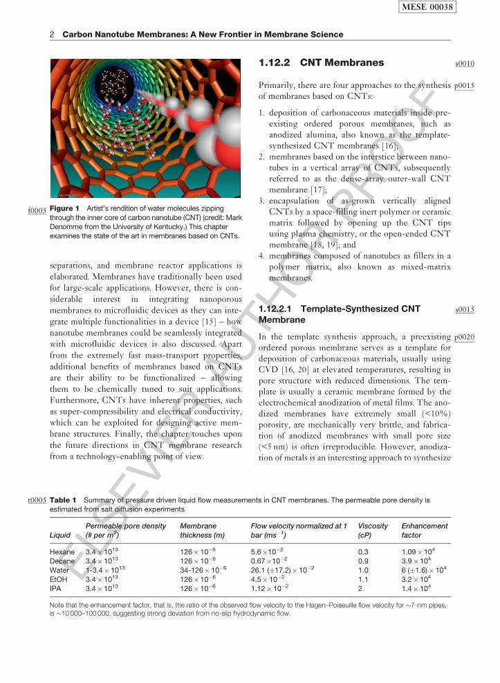
[11]. An artist’s rendition of this novel phenomenon
is shown in Figure 1, while transport properties of
liquids through the inner core of �7-nm-diameter
nanotubes are shown in Table 1. Although molecular
dynamic (MD) simulation studies indicate extremely
fast mass transport of gases and liquids through the
inner core of CNTs [12, 13], membranes fabricated
from crystalline as-formed CNTs have experimen-
tally verified these enticing mass-transport
predictions through the smooth, hydrophobic, and
crystalline interior of the nanotubes. Owing to this
significant advantage, there has been a major interest
in nanotube membranes as a technological alterna-
tive even to mature processes such as reverse osmosis
for desalination [14]. Therefore, a review showcasing
the major milestones in CNT membrane research
and their application is pertinent.p0010While the CNTs are grown by bottom-up
approaches, such as chemical vapor deposition
(CVD), fabrication of macroscopically useful mem-
branes from these nanoscale materials is often a
combination of several top-down components, such
as electrochemical anodization of a metal film, poly-
mer processing, chemical etching, and plasma
etching. We discuss the state-of-the-art approaches
for processing the CNT membranes and critically
evaluate the advantages and/or drawbacks of these
approaches. The potential of these novel membrane
materials for liquid separation, gas/vapor
MESE 00038
1
ELS
EVIE
RAU
THO
RPR
OO
F
separations, and membrane reactor applications is
elaborated. Membranes have traditionally been used
for large-scale applications. However, there is con-
siderable interest in integrating nanoporous
membranes to microfluidic devices as they can inte-
grate multiple functionalities in a device [15] – how
nanotube membranes could be seamlessly integrated
with microfluidic devices is also discussed. Apart
from the extremely fast mass-transport properties,
additional benefits of membranes based on CNTs
are their ability to be functionalized – allowing
them to be chemically tuned to suit applications.
Furthermore, CNTs have inherent properties, such
as super-compressibility and electrical conductivity,
which can be exploited for designing active mem-
brane structures. Finally, the chapter touches upon
the future directions in CNT membrane research
from a technology-enabling point of view.
s00101.12.2 CNT Membranes
p0015Primarily, there are four approaches to the synthesisof membranes based on CNTs:
1. deposition of carbonaceous materials inside pre-existing ordered porous membranes, such asanodized alumina, also known as the template-synthesized CNT membranes [16];
2. membranes based on the interstice between nano-tubes in a vertical array of CNTs, subsequentlyreferred to as the dense-array outer-wall CNTmembrane [17];
3. encapsulation of as-grown vertically alignedCNTs by a space-filling inert polymer or ceramicmatrix followed by opening up the CNT tipsusing plasma chemistry, or the open-ended CNTmembrane [18, 19]; and
4. membranes composed of nanotubes as fillers in apolymer matrix, also known as mixed-matrixmembranes.
s00151.12.2.1 Template-Synthesized CNTMembrane
p0020In the template synthesis approach, a preexistingordered porous membrane serves as a template fordeposition of carbonaceous materials, usually usingCVD [16, 20] at elevated temperatures, resulting inpore structure with reduced dimensions. The tem-plate is usually a ceramic membrane formed by theelectrochemical anodization of metal films. The ano-dized membranes have extremely small (<10%)porosity, are mechanically very brittle, and fabrica-tion of anodized membranes with small pore size(<5 nm) is often irreproducible. However, anodiza-tion of metals is an interesting approach to synthesize
Figure 1f0005 Artist’s rendition of water molecules zipping
through the inner core of carbon nanotube (CNT) (credit: MarkDenomme from the University of Kentucky.) This chapter
examines the state of the art in membranes based on CNTs.
t0005 Table 1 Summary of pressure driven liquid flow measurements in CNT membranes. The permeable pore density isestimated from salt diffusion experiments
LiquidPermeable pore density(# per m2)
Membranethickness (m)
Flow velocity normalized at 1bar (ms�1)
Viscosity(cP)
Enhancementfactor
Hexane 3.4� 1013 126� 10�6 5.6�10�2 0.3 1.09�104
Decane 3.4� 1013 126� 10�6 0.67�10�2 0.9 3.9�104
Water 1-3.4�1013 34-126�10�6 26.1 (�17.2)� 10�2 1.0 6 (�1.6)� 104
EtOH 3.4� 1013 126� 10�6 4.5�10�2 1.1 3.2�104
IPA 3.4� 1013 126� 10�6 1.12� 10�2 2 1.4�104
Note that the enhancement factor, that is, the ratio of the observed flow velocity to the Hagen–Poiseuille flow velocity for �7-nm pipes,is �10 000–100 000, suggesting strong deviation from no-slip hydrodynamic flow.
MESE 00038
2 Carbon Nanotube Membranes: A New Frontier in Membrane Science
ELS
EVIE
RAU
THO
RPR
OO
F
ordered membrane structures with controlled pore-
size distribution and small tortuosity. Although these
membranes have found applications in size-based
separations [21] and as catalytic membrane reactors
[22], further modification by carbonaceous material
deposition provides many possibilities.p0025 The synthesis and characterization of template-
synthesized membranes have been pioneered by
Charles Martin’s group at the University of Florida.
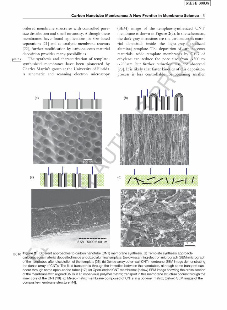
A schematic and scanning electron microscopy
(SEM) image of the template-synthesized CNT
membrane is shown in Figure 2(a). In the schematic,
the dark-gray intrusions are the carbonaceous mate-
rial deposited inside the light-gray (anodized
alumina) template. The deposition of carbonaceous
materials inside template membranes by CVD of
ethylene can reduce the pore size from �300 to
�200 nm, but further reduction was not observed
[23]. It is likely that faster kinetics of this deposition
process is less controllable for obtaining smaller
(a)
100 nm
3 KV ×5000 6.00 µm
(c) (d)
(b)
1 µm
1 µm
Figure 2f0010 Different approaches to carbon nanotube (CNT) membrane synthesis. (a) Template synthesis approach-
carbonaceous material deposited inside anodized alumina template; (below) scanning electron micrograph (SEM) micrograph
of the nanotubes after dissolution of the template [26]. (b) Dense-array outer-wall CNT membrane; SEM image demonstrating
the dense array of CNTs. The fluid transport is through the interstice between the nanotubes, although some transport canoccur through some open-ended tubes [17]. (c) Open-ended CNT membrane; (below) SEM image showing the cross section
of the membrane with aligned CNTs in an impervious polymer matrix; transport in this membrane structure occurs through the
inner core of the CNT [18]. (d) Mixed-matrix membrane composed of CNTs in a polymer matrix; (below) SEM image of the
composite-membrane structure [44].
MESE 00038
Carbon Nanotube Membranes: A New Frontier in Membrane Science 3
ELS
EVIE
RAU
THO
RPR
OO
F
dimension of pores, and is the reason for much ofMartin’s later work devoted to the use of a more-controlled solution-based electroless depositiontechnique for steric separation of small molecules[24]. This conjecture is further supported by thework of Alsyouri et al. [20], in which CVD, usingtrimethyl ammonium and water, resulted in thereduction of porosity of �20-nm templates and nottheir pore size. The CNT membranes synthesized bythis method also contain amorphous or partially gra-phitized CNTs and are chemically different from themembranes based on the highly ordered graphiticCNTs. They can, however, be graphitized by heattreatment at higher temperature. This was shown intemplate-synthesized partially graphitic nanotubes,which can be annealed at a higher temperature(>2000 �C) to form graphitic nanotubes, as evidencedby electrical conductivity, transmission electronmicroscopy, and contact angle measurements [25].It should, therefore, be possible to convert templateCNT membranes to partially graphitized CNTmembranes by heat treatment, although such treat-ments are likely to increase the cost of themembranes.
p0030 In this vein, it is worthwhile to point readers to thefabrication of well-controllable, hierarchicallybranched, and crystallized CNT architectures byAjayan and co-workers [26] using this templateapproach. The well-branched porous architecturehas smaller pore dimensions at one end and largerpore structure at the other end – similar to theasymmetric membranes commonly used for filtrationpurposes [26]. Fluid flow or permeability of thesenovel nanoscale architectures will verify its applic-ability in nanofluidic applications. A major advantageof the template synthesis approach is that the mod-ular components of thin-film deposition,electrochemical treatment, and CVD can be inte-grated to microfluidic device fabrication platforms.However, other approaches using as-formed graphi-tic CNTs seem to be more realistic for producingCNT membrane for large-scale applications. In thesubsequent sections, we discuss membranes based onas-formed CNTs.
s0020 1.12.2.2 Dense-Array Outer-Wall CNTMembrane
p0035 Aligned arrays of CNTs can be used as membranes,where transport occurs primarily through the inter-stice between the CNTs, although some of thenanotubes might be open – as shown schematically
in Figure 2(b). The CNTs, in this membrane struc-ture, are held together by van der Waals bondingbetween tubes and carbonaceous materials formedduring the CVD process. The pore size of this mem-brane is usually in the range of 40–100 nm – suitablefor ultrafiltration applications.
p0040In some cases of CNT synthesis, such as by high-pressure CO conversion (HiPco) or laser oven pro-cesses, the nanotubes are produced as an entangledmesh held together by van der Waals forces [27].Alignment of CNTs, from such an entangled mesh,can be achieved by the application of some externallyapplied forces. Partial alignment of CNTs (�50%)inside a polymer matrix can be attained by mechanicalstretching during extrusion of a polymer–nanotubecomposite melt [28, 29] – although the degree ofalignment would be limited by the high viscosity ofthe melt, especially for samples with large volumefraction of CNTs. Researchers at Rice Universitywere able to align purified SWNT bundles, in plane,using a magnetic field (�7 T) during filtration of ananotube suspension [30, 31], which is contrary toout-of-plane alignment requirements for filtrationapplication. Therefore, a particular emphasis in thefabrication of CNT membranes is formation of macro-structures with CNTs aligned perpendicular to thesubstrate. CVD from carbon-containing source and ametal catalyst can readily produce aligned CNTarrays over a substrate, such as Si and SiO2.
p0045In the early 1990s, primarily after the discovery offullerene, research efforts were directed to synthesizecarbon nanostructures in large-scale capabilities.There was also a concerted effort to produce con-trolled nanostructures composed of aligned CNTs,with the goal of investigating the anisotropic proper-ties of CNTs applicable in field-emission devices.The earliest report of aligned MWNT films was bydeHeer et al. in 1995 [32] using the arc evaporationprocess. Subsequently, other methods, such as CVD,a scalable and industrially viable process, becamepopular [33]. Aligned MWNTs were also grown onnickel-coated glass substrates by plasma-enhancedhot-filament CVD from a mixture of acetylene andammonia below 666 �C [34]; however, the CNTsproduced by this method had significant bamboo-type structures making them unsuitable for flow-through applications. Among others, efforts at theCenter for Applied Energy Research (CAER) at theUniversity of Kentucky were focused on perfectingand scaling up production of MWNT arrays from acontinuous source of ferrocene and xylene at�650 �C [35].
MESE 00038
4 Carbon Nanotube Membranes: A New Frontier in Membrane Science

ELS
EVIE
RAU
THO
RPR
OO
F
p0050 The overall geometry of the aligned CNT struc-ture depends on the shape of the substrate on whichthe CNTs are deposited. Srivastava and co-workerssucceeded in materializing this concept and formedhollow cylinders of aligned MWCNT (up to fewcentimeters long) along the walls of a tubular quartzreactor. The cylinders are composed of radiallyoriented MWNTs of about 300–500-mm length andhave been utilized for liquid and gas filtration appli-cation [17]. More importantly, the mechanicalstrength of the CNT filter is high enough to allowliquid filtration by tangential cross flow, which iswidely used in industrial membrane filtration.Molecular transport in these membranes occurred,primarily, through the interface between nanotubes,although transport through the inner core of the opennanotubes cannot be overruled. Inter-nanotube dis-tance in the MWNT arrays is in the range of 40–100 nm, which sets the pore size of the membranes. Apotential drawback of this membrane structure is theconsiderable variation in the size distribution of thefiltration pores – although these dimensions could betuned with closer packing of nanotubes or with nano-tubes of smaller outer diameter [36].
s0025 1.12.2.3 Open-Ended CNT Membrane
p0055 A contemporary approach in CNT membraneresearch is the use of open-ended CNT channels asconduits for molecular transport. A composite film issynthesized from an aligned array of the CNT by aspace-filling polymer [18] or ceramic matrix [19];however, maintaining the alignment of the CNTsduring this processing step is critical. Subsequently,the tips of the CNTs are oxidized by plasma chem-istry to form open-ended and conducting CNTchannels. A schematic and SEM image of a typicalnanotube membrane fabricated by such a process isdepicted in Figure 2(c).
p0060 The open-ended CNT membranes, with space-filling polymers, have been primarily based on poly(-styrene) [18]. The choice of poly(styrene) in thiswork is dictated by its high wettability [37] withCNTs allowing easy penetration into the MWCNTarray (�1010 tubes cm�2) by a simple film fabricationprocess. However, other mechanically robust poly-mers and conformal deposition techniques cansubstitute polystyrene. The CNT–polymer film isreleased from the quartz substrate, on which theCNTs grow, by hydrofluoric acid (HF) etch. Thevertically oriented CNTs in the polymer matrixoften have a graphitic end cap (which have larger
concentration of defects and are easily oxidized com-
pared to the side walls) or a catalyst metal particle
sealing the graphitic interiors, which are etched away
using mild plasma oxidation without destroying the
mechanical structure of the CNTs [38]. High-tem-
perature oxidative [39] or acidic oxidation
treatments can compromise the mechanical integrity
of the membrane and are not suitable for the mem-
brane fabrication process. The elegance of the
plasma-oxidation process stems from its controllable
oxidation kinetics, and the ability to fabricate a
macroscopic CNT array device. This plasma-oxida-
tion process, inherent to the membrane fabrication
process, performs three very important functions:
1. It removes excess polymers by oxidative trim-ming, since the oxidation kinetics of the polymer
(CNT) is faster than that of the CNTs. This
results in the exposure of the CNTs out of the
polymer matrix, making the membrane electri-
cally conducting.2. The plasma-oxidation process also removes amor-
phous carbon and Fe impurities, aided by HCl
treatment. Note that the permeable pore densities
(�109 cm�2) of membranes in Table 1, estimated
from salt-diffusion experiments, are almost a mag-
nitude smaller than the density of the CNTs in the
arrays (�1010 cm�2) estimated from microscopy
experiments. This is attributed to the incomplete
removal of the iron nanocrystals from the interiors
of the CNTs.3. The plasma-oxidation process introduces func-
tional groups (mainly –COOH) at the CNT tips,
which makes the tips amenable to facile functio-
nalization-chemistry approaches.
The CNT membrane structure after the plasma-oxidation process showed a BET AU4pore-size distri-bution of �6� 2 nm, which is consistent withTEM observations of the inner core of �7 nm.
p0065In a similar work, aligned CNTs (with sub-2-nmdiameter) were grown on a Si chip patterned with
metal catalyst using a CVD process. A conformal
deposition of a ceramic material, Si3N4, filled up
the space between the nanotubes. Standard etching
procedures were adopted to create openings on the Si
chip; subsequently, excess Si3N4 and catalyst nano-
particles were removed by Ar-ion milling, while the
CNTs were uncapped by reactive ion etching [19].
In both these works, the production of the CNT
membranes relied on standard lithography tools
commonly associated with microelectronic industry.
MESE 00038
Carbon Nanotube Membranes: A New Frontier in Membrane Science 5

ELS
EVIE
RAU
THO
RPR
OO
F
p0070 More traditional inorganic membrane fabricationresearch groups have focused on making robust andcost-efficient CNT membranes by using macropor-ous membrane support layer and avoiding the use oflithographic tools. In this effort, aligned CNT arrayswere grown over macroporous alumina supports andthe interstitial space between the CNTs was filled bypoly(styrene); however, the viscosity of the polymerwas high enough to preclude its entry into the macro-porous alumina support. Mechanical polishing andacid treatment were adopted to remove the polymeroverlayer and to open up the CNTs [40].
p0075 The methodologies for fabrication of the first-generation CNT membranes were aimed at under-standing the fundamental transport behavior. Theysuffer from several drawbacks, for example, the por-osity of the these membranes and the overallpermeability is uncertain, due to the presence ofconsiderable amount of Fe nanocrystals from thevapor deposition process and the overall yield ispainstakingly small. The research approaches dis-cussed earlier [18, 19, 40] have utilized as-formedaligned CNTs for the fabrication of membranes; analternative route is to adapt colloidal processingapproaches. In this regard, Kim et al. [41] claim tohave developed a scalable process for the fabricationof open-ended nanotube membranes by filtering aCNT suspension through a hydrophobic porouspolytetrafluoroethylene (PTFE, 0.2-mm porediameter).AU5 Quite surprisingly, a substantial number(�1010 cm�2) of CNTs were observed to stick out ofthe filter surface, most likely due to the hydropho-bic–hydrophobic interaction between the nanotubesand the filter surface. A thin polymer binder filled upthe interstice between the nanotubes, leading to theformation of the membrane. The key advantage ofthis approach lies in the ability to use purified nano-tubes (lower amount of Fe catalyst) with largerthrough porosity and to use diameter-sorted CNTsuspensions. Scalability and the overall simplicity ofthe colloidal approach have the potential to lower thecost of CNT membrane fabrication.
p0080 In sum, the fabrication of the open-ended CNTmembranes is complex, but it offers tighter controlover pore size as the transport occurs through theinner core of CNTs.
s0030 1.12.2.4 Mixed-Matrix CNT Membranes
p0085 Polymeric membrane materials are intrinsically lim-ited by a tradeoff between their permeability andtheir selectivity, yet they have been the basis for
high-performance gas-separation applications.Virtually, all gas separations in polymeric mem-branes are limited by an upper boundary in a log–log plot of gas selectivity and permeability [42]. Oneapproach to increase the selectivity is to includedispersions of inorganic nanoparticles, such as zeo-lites, carbon molecular sieves, or CNTs, into thepolymeric membranes – these membranes are classi-fied as mixed-matrix membranes. In thesemembranes, the choice of both these components isa problem of materials selection, and also involvesseveral fundamental issues, such as polymer-chainrigidity, free volume, and the altered interface – allof which influence transport through the membrane[43]. Several research groups are investigating theeffects of incorporation of CNTs to develop mixed-matrix membranes. Schematic and SEM image ofmixed-matrix CNT membranes are shown inFigure 2(d). In the dense-array or open-endedCNT membranes, transport is through the pores ofCNTs and interparticle pores in CNT array – amechanism quite similar to porous ultrafiltration ornanofiltration membranes, whereas transport throughthe mixed-matrix membranes is predominantly by asolution–diffusion mechanism. Eva Marand and co-workers have incorporated open-ended and amine-functionalized CNTs (with �13.6-A pore diameter)into poly(sulfone) [44] and poly(imide-siloxane)copolymer [45]. Incorporation of CNTs increasesthe permeability of most gases by up to 60%, butthe selectivity does not improve compared to thepolymeric membranes. However, appropriate manip-ulation of the interface can significantly improve theseparation performance. Considering the plethora ofpolymeric materials at the disposal, the combinator-ial selection of components for membraneformulation may pose a problem of plenty.Therefore, modeling and simulations are needed forpredicting the transport properties of the mixed-matrix membranes a priori. Further, rational designof experiments for optimization of materials proces-sing and property relationships can pave the way forthe development of high-performance CNT-basedmixed-matrix membranes.
s00351.12.3 Properties and Applicationof CNT Membranes
p0090In this section, we discuss the properties of the CNTmembrane with particular emphasis on their poten-tial applications.
MESE 00038
6 Carbon Nanotube Membranes: A New Frontier in Membrane Science