a10 thunder threat protection system deployment guide · the a10 networks® a10 thunder™ threat...
TRANSCRIPT
DEPLOYMENT GUIDE
Customer Driven Innovation
A10 ThunderThreat Protection System
1Customer Driven Innovation
Deployment Guide | A10 Thunder Threat Protection System
DisclaimerThis document does not create any express or implied warranty about A10 Networks or about its products or services, including but not limited to
fitness for a particular use and noninfringement. A10 Networks has made reasonable efforts to verify that the information contained herein is accurate,
but A10 Networks assumes no responsibility for its use. All information is provided “as-is.” The product specifications and features described in this
publication are based on the latest information available; however, specifications are subject to change without notice, and certain features may not
be available upon initial product release. Contact A10 Networks for current information regarding its products or services. A10 Networks’ products and
services are subject to A10 Networks’ standard terms and conditions.
Table of Contents1 Overview ...................................................................................................................................................................................................................................2
2 Solution ......................................................................................................................................................................................................................................2
3 Deployment Prerequisites ..............................................................................................................................................................................................3
4 Deployment Modes ............................................................................................................................................................................................................3
4.1 Asymmetric Reactive Mode ................................................................................................................................................................................3
4.2 Asymmetric Proactive Mode ..............................................................................................................................................................................7
4.3 Symmetric Mode .......................................................................................................................................................................................................8
4.4 Out-of-band (TAP) Mode ...................................................................................................................................................................................10
5 Third-Party Integration ...................................................................................................................................................................................................11
5.1 Integrating NFDUMP & NFSEN by using sFlow ...................................................................................................................................11
5.2 Integrating InMon sFlow RT ...........................................................................................................................................................................13
5.3 GRE Tunneling to a Cisco Cloud Services Router (CSR) 1000v ...................................................................................................13
6 Summary ................................................................................................................................................................................................................................16
About A10 Networks ..............................................................................................................................................................................................................17
2
Deployment Guide | A10 Thunder Threat Protection System
Customer Driven Innovation
1 OverviewOrganizations are increasingly dependent on the availability of their services and their ability to connect to the Internet. Downtime results in immediate revenue loss. One of the largest persistent threats to service uptime is Distributed Denial of Service Attacks (DDoS). The networking industry and business analysts are seeing a trend in increasing DDoS attacks.
These attacks are occurring more frequently and with greater volumes and increased sophistication. Legacy DDoS protection solutions suffer from the following fatal limitations that have made them ineffective at protecting against these attacks:
• Lack of flexibility
• Inability to scale
The A10 Networks® A10 Thunder™ Threat Protection System (TPS) has been designed from the ground up to address these problems and protect services and connectivity from the next generation of threats.
2 SolutionThe A10 Thunder TPS product line provides high-performance, network-wide protection from DDoS attacks and maintains service availability against a variety of volumetric, protocol, resource, and other sophisticated application attacks by offering flexible deployment options.
• Multi-vector application & network protection
- Detect and mitigate application and network attacks
- Flexible scripting and deep packet inspection (DPI) for rapid response
• High performance mitigation
- Mitigate maximum 155 Gbps of attack throughput
- Mitigate maximum 200 million packets per second
• Broad deployment options
- Symmetric, Asymmetric, Out-of-Band (TAP) deployment options
› Routed (L3), Transparent (L2) modes
› BGP, Tunneling protocols (GRE and IP-in-IP) and else
• Open SDK / RESTful API (aXAPI) for third party integration
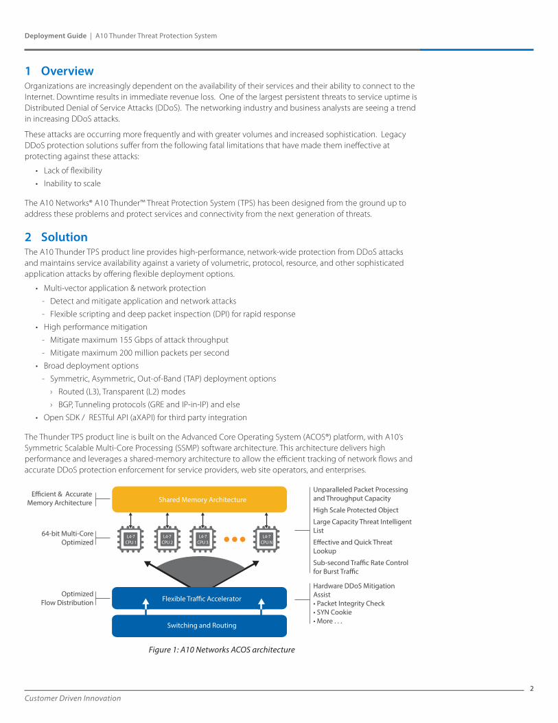
The Thunder TPS product line is built on the Advanced Core Operating System (ACOS®) platform, with A10’s Symmetric Scalable Multi-Core Processing (SSMP) software architecture. This architecture delivers high performance and leverages a shared-memory architecture to allow the efficient tracking of network flows and accurate DDoS protection enforcement for service providers, web site operators, and enterprises.
Figure 1: A10 Networks ACOS architecture
Flexible Tra�c Accelerator
Switching and Routing
E�cient & AccurateMemory Architecture
64-bit Multi-CoreOptimized
OptimizedFlow Distribution
L4-7CPU 1
L4-7CPU 2
L4-7CPU 3
L4-7CPU N
Shared Memory ArchitectureUnparalleled Packet Processingand Throughput Capacity
High Scale Protected Object
Large Capacity Threat IntelligentList
E�ective and Quick ThreatLookup
Sub-second Tra�c Rate Controlfor Burst Tra�c
Hardware DDoS MitigationAssist• Packet Integrity Check• SYN Cookie• More . . .
3Customer Driven Innovation
Deployment Guide | A10 Thunder Threat Protection System
3 Deployment PrerequisitesTo deploy Thunder TPS, you need the following:
• Thunder TPS 4435(S), 5435(S), or 6435(S)
• ACOS TPS release 3.0 or higher
Enter the following default information to log in to A10 Networks Thunder Series:
• Username: admin• Password: a10• Management IP address of the device: 172.31.31.31
4 Deployment ModesThe deployment topologies that are addressed in this guide generally dictate the following:
• Whether the device is monitoring both directions of traffic (Asymmetric / Symmetric)
• Whether the device is in the data path at all times (Reactive / Proactive)
• Whether the device is only monitoring the data path (Out-of-band)
This guide provides comprehensive information about the topologies and the modes.
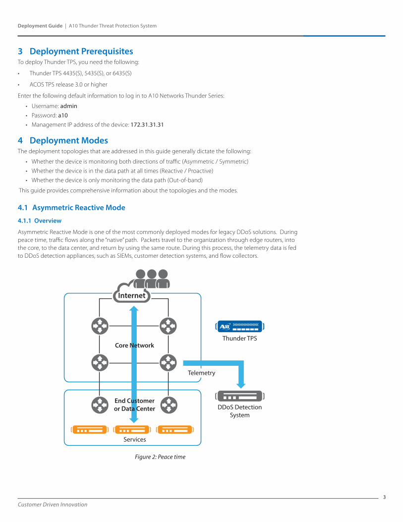
4.1 Asymmetric Reactive Mode
4.1.1 Overview
Asymmetric Reactive Mode is one of the most commonly deployed modes for legacy DDoS solutions. During peace time, traffic flows along the “native” path. Packets travel to the organization through edge routers, into the core, to the data center, and return by using the same route. During this process, the telemetry data is fed to DDoS detection appliances, such as SIEMs, customer detection systems, and flow collectors.
Figure 2: Peace time
Internet
Services
DDoS DetectionSystem
Thunder TPSCore Network
End Customeror Data Center
Telemetry
4
Deployment Guide | A10 Thunder Threat Protection System
Customer Driven Innovation
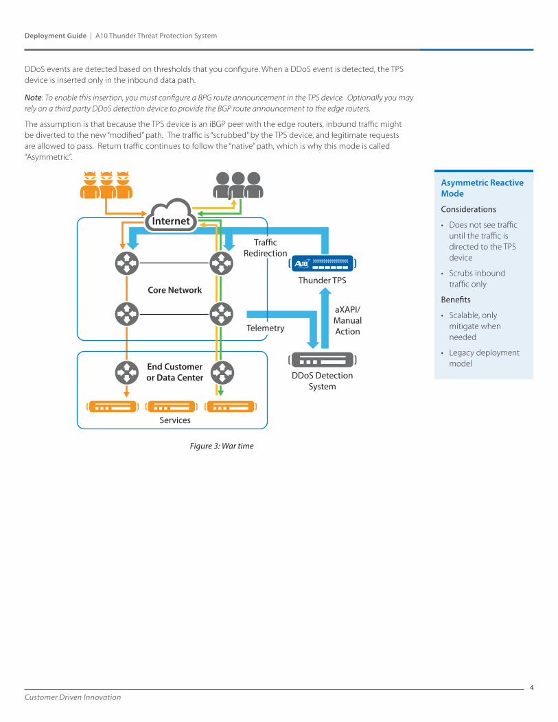
DDoS events are detected based on thresholds that you configure. When a DDoS event is detected, the TPS device is inserted only in the inbound data path.
Note: To enable this insertion, you must configure a BPG route announcement in the TPS device. Optionally you may rely on a third party DDoS detection device to provide the BGP route announcement to the edge routers.
The assumption is that because the TPS device is an iBGP peer with the edge routers, inbound traffic might be diverted to the new “modified” path. The traffic is “scrubbed” by the TPS device, and legitimate requests are allowed to pass. Return traffic continues to follow the “native” path, which is why this mode is called “Asymmetric”.
Figure 3: War time
Internet
Services
DDoS DetectionSystem
Thunder TPSCore Network
aXAPI/ManualAction
End Customeror Data Center
Tra�cRedirection
Telemetry
Asymmetric Reactive Mode
Considerations
• Does not see traffic until the traffic is directed to the TPS device
• Scrubs inbound traffic only
Benefits
• Scalable, only mitigate when needed
• Legacy deployment model
5Customer Driven Innovation
Deployment Guide | A10 Thunder Threat Protection System
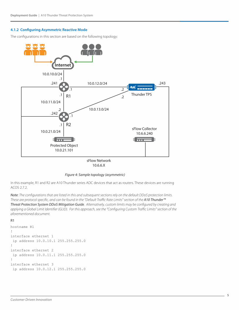
4.1.2 Configuring Asymmetric Reactive Mode
The configurations in this section are based on the following topology:
Figure 4: Sample topology (asymmetric)
In this example, R1 and R2 are A10 Thunder series ADC devices that act as routers. These devices are running ACOS 2.7.2.
Note: The configurations that are listed in this and subsequent sections rely on the default DDoS protection limits. These are protocol specific, and can be found in the “Default Traffic Rate Limits” section of the A10 Thunder™ Threat Protection System DDoS Mitigation Guide. Alternatively, custom limits may be configured by creating and applying a Global Limit Identifier (GLID). For this approach, see the “Configuring Custom Traffic Limits” section of the aforementioned document.
R1
hostname R1!interface ethernet 1 ip address 10.0.10.1 255.255.255.0!interface ethernet 2 ip address 10.0.11.1 255.255.255.0! interface ethernet 3 ip address 10.0.12.1 255.255.255.0
Internet
Thunder TPS
10.0.12.0/24
10.0.21.0/24
10.0.11.0/24
10.0.13.0/24
.1
.1
.1
.1
R1
R2
.1 .2
.2
.2
.241
.242
Protected Object10.0.21.101
sFlow Collector10.6.6.240
sFlow Network10.6.6.X
.243
10.0.10.0/24
6
Deployment Guide | A10 Thunder Threat Protection System
Customer Driven Innovation
!interface ethernet 4 ip address 10.6.6.241 255.255.255.0!router bgp 64512 neighbor 10.0.11.2 remote-as 64512 neighbor 10.0.12.2 remote-as 64512!sflow collector 10.6.6.240 10241sflow packet-sampling-rate 10sflow polling ethernet 1 interval 1sflow sampling ethernet 1 rate 10enable-management service ssh ethernet 4
R2
hostname R2!interface ethernet 1 ip address 10.0.11.2 255.255.255.0!interface ethernet 2 ip address 10.0.13.1 255.255.255.0! interface ethernet 3 ip address 10.0.21.1 255.255.255.0!interface ethernet 4 ip address 10.6.6.242 255.255.255.0!ip route 0.0.0.0 /0 10.0.11.1!router bgp 64512 network 10.0.21.0/24 neighbor 10.0.11.1 remote-as 64512!sflow collector 10.6.6.240 10242sflow packet-sampling-rate 10sflow polling ethernet 1 interval 1sflow sampling ethernet 1 rate 10enable-management service ssh ethernet 4
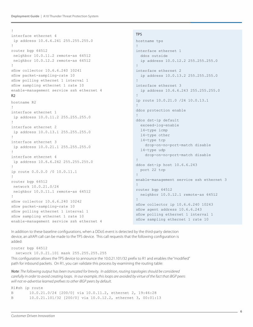
In addition to these baseline configurations, when a DDoS event is detected by the third-party detection device, an aXAPI call can be made to the TPS device. This call requests that the following configuration is added:
router bgp 64512 network 10.0.21.101 mask 255.255.255.255
This configuration allows the TPS device to announce the 10.0.21.101/32 prefix to R1 and enables the “modified” path for inbound packets. On R1, you can validate this process by examining the routing table:
Note: The following output has been truncated for brevity. In addition, routing topologies should be considered carefully in order to avoid creating loops. In our example, this loops are avoided by virtue of the fact that iBGP peers will not re-advertise learned prefixes to other iBGP peers by default.
R1#sh ip routeB 10.0.21.0/24 [200/0] via 10.0.11.2, ethernet 2, 19:46:28B 10.0.21.101/32 [200/0] via 10.0.12.2, ethernet 3, 00:01:13
TPS
hostname tps !interface ethernet 1 ddos outside ip address 10.0.12.2 255.255.255.0 !interface ethernet 2 ip address 10.0.13.2 255.255.255.0 !interface ethernet 3 ip address 10.6.6.243 255.255.255.0 !ip route 10.0.21.0 /24 10.0.13.1 ! ddos protection enable !ddos dst-ip default exceed-log-enable l4-type icmp l4-type other l4-type tcp drop-on-no-port-match disable l4-type udp drop-on-no-port-match disable !ddos dst-ip host 10.6.6.243 port 22 tcp !enable-management service ssh ethernet 3! router bgp 64512 neighbor 10.0.12.1 remote-as 64512 !sflow collector ip 10.6.6.240 10243 sflow agent address 10.6.6.243 sflow polling ethernet 1 interval 1 sflow sampling ethernet 1 rate 10
7Customer Driven Innovation
Deployment Guide | A10 Thunder Threat Protection System
In addition, the aXAPI call can create a protected object, a very simple example being:
ddos dst entry “web1” 10.0.21.101 port 80 tcp
In the configuration, the telemetry data is sent by using sFlow to a collector at 10.6.6.240, but this collector is not configured to make control plane API calls. For more information about this box, see Integrating NFDUMP & NFSEN by using sFlow.
For more information about configuring Thunder series devices by using aXAPI, see the aXAPI Reference documentation and the ACOS 3.0 Software Development Kit (SDK).
Note: Although these configurations reflect a layer 3 approach, layer 2 (transparent) configurations are supported. For more information, see the A10 Thunder™ Threat Protection System DDoS Mitigation Guide.
4.2 Asymmetric Proactive Mode
4.2.1 Overview
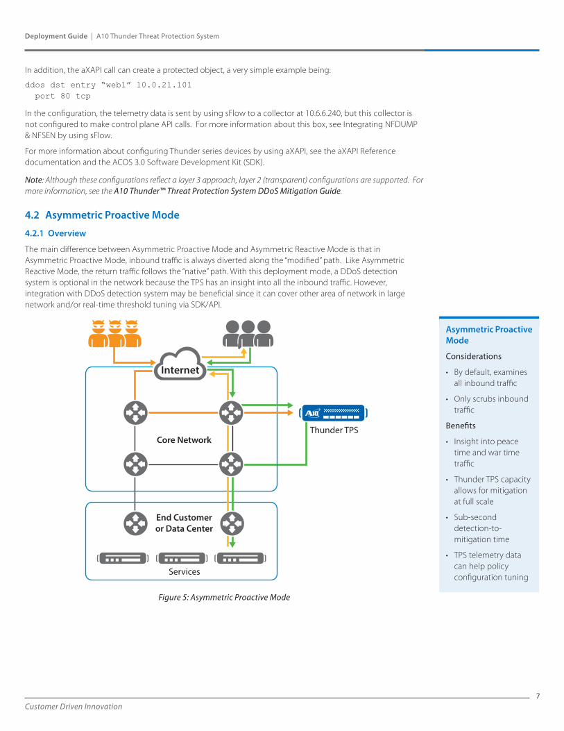
The main difference between Asymmetric Proactive Mode and Asymmetric Reactive Mode is that in Asymmetric Proactive Mode, inbound traffic is always diverted along the “modified” path. Like Asymmetric Reactive Mode, the return traffic follows the “native” path. With this deployment mode, a DDoS detection system is optional in the network because the TPS has an insight into all the inbound traffic. However, integration with DDoS detection system may be beneficial since it can cover other area of network in large network and/or real-time threshold tuning via SDK/API.
Figure 5: Asymmetric Proactive Mode
Internet
Services
Thunder TPSCore Network
End Customeror Data Center
Asymmetric Proactive Mode
Considerations
• By default, examines all inbound traffic
• Only scrubs inbound traffic
Benefits
• Insight into peace time and war time traffic
• Thunder TPS capacity allows for mitigation at full scale
• Sub-second detection-to-mitigation time
• TPS telemetry data can help policy configuration tuning
8
Deployment Guide | A10 Thunder Threat Protection System
Customer Driven Innovation
4.2.2 Configuring Asymmetric Proactive Mode
Asymmetric Proactive Mode can be configured to be identical to Asymmetric Reactive Mode. The notable difference is that, instead of being withdrawn after traffic patterns return to their peace time baselines, the following configuration on the TPS device remains persistent:
router bgp 64512 network 10.0.21.101 mask 255.255.255.255
ddos dst entry “web1” 10.0.21.101 port 80 tcp
Note: Although these configurations reflect a layer 3 approach, layer 2 (transparent) configurations are supported. In addition, you may optionally configure DDoS protection mechanisms to kick in once a threshold is reached in Asymmetric Proactive Mode. For more information, see the A10 Thunder™ Threat Protection System DDoS Mitigation Guide.
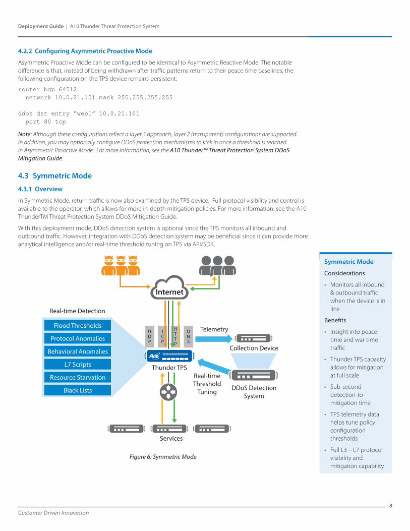
4.3 Symmetric Mode
4.3.1 Overview
In Symmetric Mode, return traffic is now also examined by the TPS device. Full protocol visibility and control is available to the operator, which allows for more in-depth mitigation policies. For more information, see the A10 ThunderTM Threat Protection System DDoS Mitigation Guide.
With this deployment mode, DDoS detection system is optional since the TPS monitors all inbound and outbound traffic. However, integration with DDoS detection system may be beneficial since it can provide more analytical intelligence and/or real-time threshold tuning on TPS via API/SDK.
Figure 6: Symmetric Mode
UDP
TCP
HTTP
DNS
Internet
Services
Telemetry
Collection Device
DDoS DetectionSystem
Real-time Detection
Real-timeThreshold
Tuning
Thunder TPS
Flood Thresholds
Protocol Anomalies
Behavioral Anomalies
L7 Scripts
Resource Starvation
Black Lists
Symmetric Mode
Considerations
• Monitors all inbound & outbound traffic when the device is in line
Benefits
• Insight into peace time and war time traffic
• Thunder TPS capacity allows for mitigation at full scale
• Sub-second detection-to-mitigation time
• TPS telemetry data helps tune policy configuration thresholds
• Full L3 – L7 protocol visibility and mitigation capability
9Customer Driven Innovation
Deployment Guide | A10 Thunder Threat Protection System
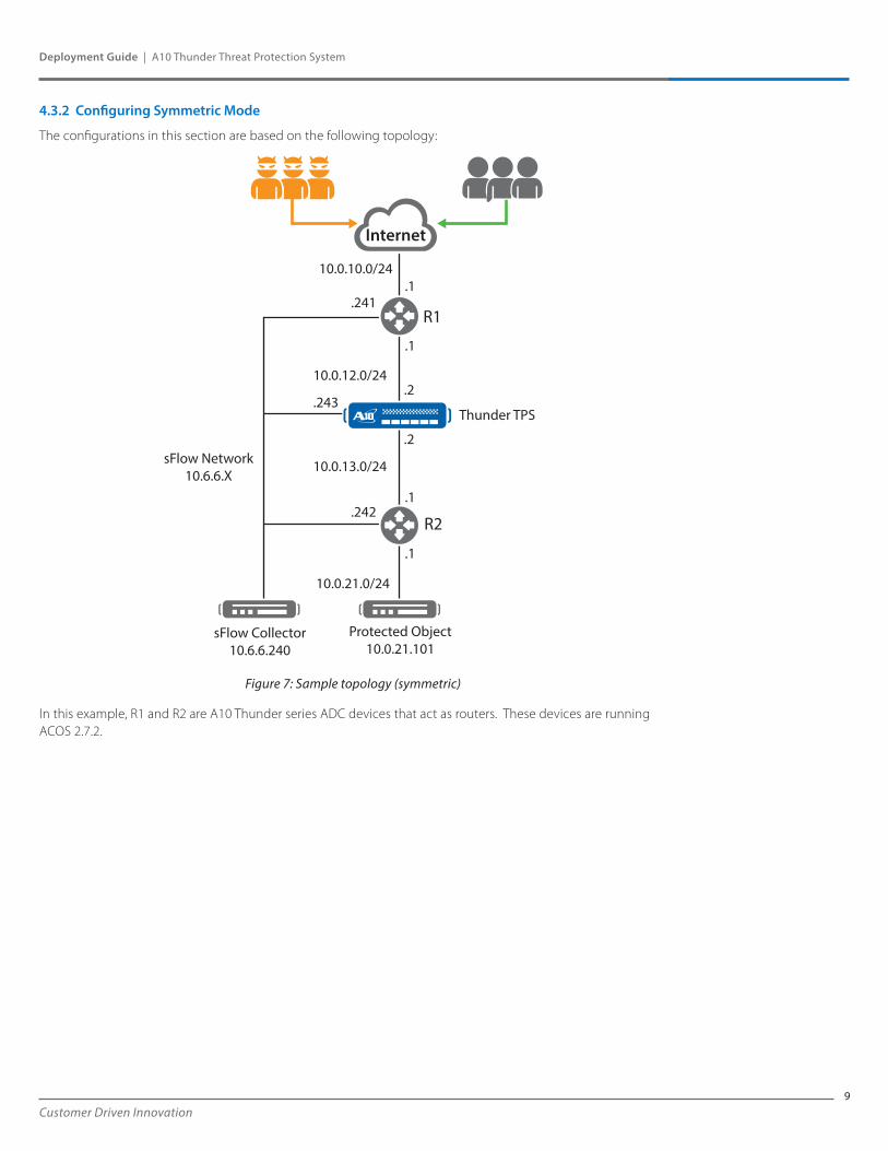
4.3.2 Configuring Symmetric Mode
The configurations in this section are based on the following topology:
Figure 7: Sample topology (symmetric)
In this example, R1 and R2 are A10 Thunder series ADC devices that act as routers. These devices are running ACOS 2.7.2.
.243
Internet
Thunder TPS
10.0.21.0/24
10.0.13.0/24
10.0.12.0/24
.1
.1
.1
R1
R2
.2
.2
.1
.241
.242
Protected Object10.0.21.101
sFlow Collector10.6.6.240
sFlow Network10.6.6.X
10.0.10.0/24
10
Deployment Guide | A10 Thunder Threat Protection System
Customer Driven Innovation
R1
hostname R1!interface ethernet 1 ip address 10.0.10.1 255.255.255.0! interface ethernet 2 ip address 10.0.12.1 255.255.255.0!interface ethernet 3 ip address 10.6.6.241 255.255.255.0!ip route 10.0.21.0 /24 10.0.12.2!sflow collector 10.6.6.240 10241sflow packet-sampling-rate 10sflow polling ethernet 1 interval 1sflow sampling ethernet 1 rate 10enable-management service ssh ethernet 3
R2
hostname R2!interface ethernet 1 ip address 10.0.13.1 255.255.255.0! interface ethernet 2 ip address 10.0.21.1 255.255.255.0!interface ethernet 3 ip address 10.6.6.242 255.255.255.0!ip route 0.0.0.0 /0 10.0.13.2!sflow collector 10.6.6.240 10242sflow packet-sampling-rate 10sflow polling ethernet 1 interval 1sflow sampling ethernet 1 rate 10enable-management service ssh ethernet 3
In these configurations, telemetry data is sent by using sFlow to a collector at 10.6.6.240. For more information about this box, see Integrating NFDUMP & NFSEN by using sFlow.
Note: Although these configurations reflect a layer 3 approach, layer 2 (transparent) configurations are also supported. For more information, see the A10 Thunder™ Threat Protection System DDoS Mitigation Guide.
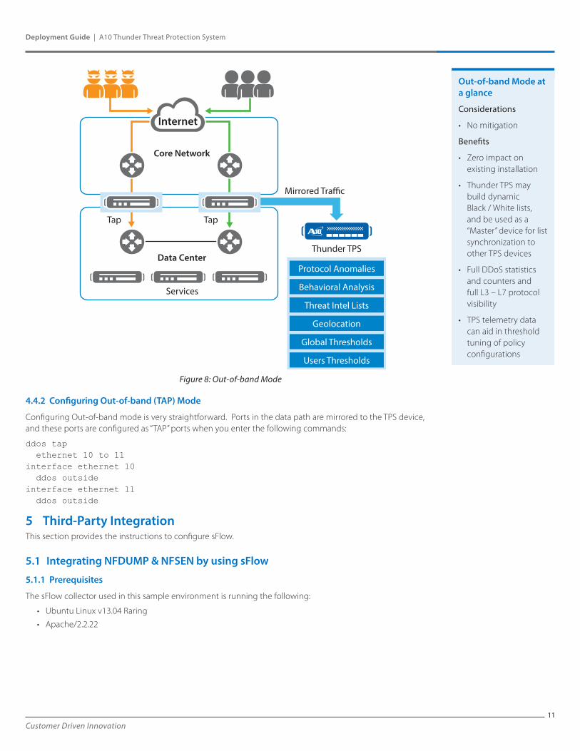
4.4 Out-of-band (TAP) Mode
4.4.1 Overview
Out-of-band Mode is designed for operators who want high-speed DDoS detection visibility without mitigation. Traffic is mirrored off of the “native” path to the TPS device. The device receives this traffic and analyzes the corresponding data based on the policy configuration. This is useful in scenarios where operators want to gather telemetry to formulate policy decisions or develop dynamic white lists / black lists and act as a “master” to other TPS devices.
TPS
hostname tps !interface ethernet 1 ddos outside ip address 10.0.12.2 255.255.255.0 !interface ethernet 2 ddos inside ip address 10.0.13.2 255.255.255.0 !interface ethernet 3 ip address 10.6.6.243 255.255.255.0 !ip route 10.0.21.0 /24 10.0.13.1 ip route 0.0.0.0 /0 10.0.12.1! ddos protection enable !ddos dst-ip default exceed-log-enable l4-type icmp l4-type other l4-type tcp drop-on-no-port-match disable l4-type udp drop-on-no-port-match disable !ddos dst-ip host 10.6.6.243 port 22 tcp !enable-management service ssh ethernet 3!sflow collector ip 10.6.6.240 10243 sflow agent address 10.6.6.243 sflow polling ethernet 1 interval 1 sflow sampling ethernet 1 rate 10
11Customer Driven Innovation
Deployment Guide | A10 Thunder Threat Protection System
Figure 8: Out-of-band Mode
4.4.2 Configuring Out-of-band (TAP) Mode
Configuring Out-of-band mode is very straightforward. Ports in the data path are mirrored to the TPS device, and these ports are configured as “TAP” ports when you enter the following commands:
ddos tap ethernet 10 to 11interface ethernet 10 ddos outsideinterface ethernet 11 ddos outside
5 Third-Party IntegrationThis section provides the instructions to configure sFlow.
5.1 Integrating NFDUMP & NFSEN by using sFlow
5.1.1 Prerequisites
The sFlow collector used in this sample environment is running the following:
• Ubuntu Linux v13.04 Raring
• Apache/2.2.22
Internet
Services
Thunder TPS
Core Network
Mirrored Tra�c
Data Center
Tap Tap
Protocol Anomalies
Behavioral Analysis
Threat Intel Lists
Geolocation
Global Thresholds
Users Thresholds
Out-of-band Mode at a glance
Considerations
• No mitigation
Benefits
• Zero impact on existing installation
• Thunder TPS may build dynamic Black / White lists, and be used as a “Master” device for list synchronization to other TPS devices
• Full DDoS statistics and counters and full L3 – L7 protocol visibility
• TPS telemetry data can aid in threshold tuning of policy configurations
12
Deployment Guide | A10 Thunder Threat Protection System
Customer Driven Innovation
5.1.2 Setup Sequence
1. Install some of the required base packages by entering the following commands:
sudo apt-get install flex sudo apt-get install rrdtoolsudo apt-get install librrd-devsudo apt-get install perl-byaccsudo apt-get install php5 sudo apt-get install librrds-perl
2. Download, compile, and install NFDUMP by entering the following commands:
cd ~wget http://sourceforge.net/projects/nfdump/files/stable/nfdump-1.6.11/nfdump-1.6.11.tar.gztar -xvzf nfdump-1.6.11.tar.gz cd nfdump-1.6.11/./configure --enable-nfprofile --enable-sflow sudo makesudo make install
3. Download NFSEN and set up the file directory structure by entering the following commands:
cd ~wget http://sourceforge.net/projects/nfsen/files/stable/nfsen-1.3.6p1/nfsen-1.3.6p1.tar.gztar -xvzf nfsen-1.3.6p1.tar.gz cd nfsen-1.3.6p1/cp etc/nfsen-dist.conf etc/nfsen-dist.conf.bkupsudo mkdir –p /data/nfsensudo chmod -Rf 777 /data/nfsen
4. Edit the NFSEN configuration file and modify the following values by entering the following commands:
nano etc/nfsen-dist.conf
================etc/nfsen-dist.conf changes==================$WWWUSER = “www-data”;$WWWGROUP = “www-data”;
%sources = ( ‘R1’ => { ‘port’ => ‘10241’, ‘col’ => ‘#ff0000’, ‘type’ => ‘sflow’ }, ‘R2’ => { ‘port’ => ‘10242’, ‘col’ => ‘#00ff00’, ‘type’ => ‘sflow’ }, ‘TPS’ => { ‘port’ => ‘10243’, ‘col’ => ‘#0000ff’, ‘type’ => ‘sflow’ },);================ etc/nfsen-dist.conf changes ==================
5. Set up the required users and groups by entering the following commands:
sudo useradd netflowsudo usermod -G www-data netflow
6. Install and start NFSEN by entering the following commands:
sudo ./install.pl etc/nfsen-dist.confsudo /etc/init.d/apache2 restartsudo ~/nfsen/bin/nfsen start
13Customer Driven Innovation
Deployment Guide | A10 Thunder Threat Protection System
7. Ensure that the startup of NFDUMP & NFSEN is automatic across reboots by entering the following commands:
sudo ln -s /data/nfsen/bin/nfsen /etc/init.d/nfsensudo update-rc.d nfsen defaults 20
8. Configure the TPS device for sFlow by entering the following commands:
sflow collector ip 10.6.6.240 10243sflow agent address 10.6.6.243sflow polling ethernet 1 interval 1sflow sampling ethernet 1 rate 10
5.2 Integrating InMon sFlow RT
5.2.1 Prerequisites
The sFlow collector in this sample environment is running Ubuntu Linux v13.04 Raring.
5.2.2 Setup Sequence
1. Install some of the required base packages (Java 1.6+) by entering the following commands:
sudo apt-get install openjdk-7-jre openjdk-7-jdk icedtea-7-plugin
2. Download and extract sFlow RT by entering the following commands:
wget http://www.inmon.com/products/sFlow-RT/sflow-rt.tar.gz tar -xvzf sflow-rt.tar.gz cd sflow-rt
3. Start sFlow RT by entering the following command:
./start.sh
4. Configure the TPS device for sFlow by entering the following commands:
sflow collector ip 10.6.6.240 6343 sflow agent address 10.6.6.243 sflow polling ethernet 1 interval 1 sflow sampling ethernet 1 rate 10
5.3 GRE Tunneling to a Cisco Cloud Services Router (CSR) 1000v
5.3.1 Prerequisites
The Cisco CSR 1000v was tested by using the following versions:
• VMWare ESXi 5.1.0 build-79973
• Cisco IOS-XE Software, version 03.11.00.S – Standard Support
• Cisco IOS Software, CSR1000V Software (X86_64_LINUX_IOSD-UNIVERSALK9-M), Version 15.4(1)S
14
Deployment Guide | A10 Thunder Threat Protection System
Customer Driven Innovation
5.3.2 Setup Sequence
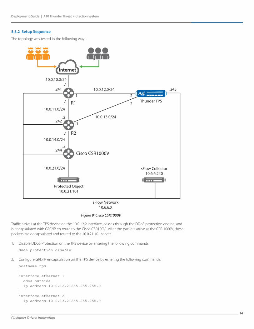
The topology was tested in the following way:
Figure 9: Cisco CSR1000V
Traffic arrives at the TPS device on the 10.0.12.2 interface, passes through the DDoS protection engine, and is encapsulated with GRE/IP en route to the Cisco CSR100V. After the packets arrive at the CSR 1000V, these packets are decapsulated and routed to the 10.0.21.101 server.
1. Disable DDoS Protection on the TPS device by entering the following commands:
ddos protection disable
2. Configure GRE/IP encapsulation on the TPS device by entering the following commands:
hostname tps! interface ethernet 1 ddos outside ip address 10.0.12.2 255.255.255.0!interface ethernet 2 ip address 10.0.13.2 255.255.255.0
Internet
Thunder TPS
10.0.12.0/24
10.0.21.0/24
10.0.11.0/24
10.0.14.0/24
10.0.13.0/24
.1
.1
.1
.1
R1
R2
Cisco CSR1000V
.1 .2
.2
.2
.2
.241
.242
.244
Protected Object10.0.21.101
sFlow Collector10.6.6.240
sFlow Network10.6.6.X
.243
10.0.10.0/24
15Customer Driven Innovation
Deployment Guide | A10 Thunder Threat Protection System
!interface ethernet 3 ip address 10.6.6.243 255.255.255.0!!ip route 10.0.14.0 /24 10.0.13.1!ddos protection disable!ddos template tcp “gretemp” tunnel-encap gre always 10.0.14.2!!ddos dst entry “web1” 10.0.21.101 l4-type tcp disable-syn-auth
port 80 tcp template tcp “gretemp”!!ddos dst interface-ip 10.6.6.243 port 22 tcp!!enable-management service ssh ethernet 3!system ddos-attack log!router bgp 64512 neighbor 10.0.12.1 remote-as 64512!!
3. Configure the CSR1000V device by entering the following commands:
version 15.4platform console virtual!hostname CSR1000V!!interface Tunnel0ip address 172.16.10.1 255.255.255.0tunnel source GigabitEthernet2tunnel destination 10.0.13.2!interface GigabitEthernet1ip address 10.6.6.244 255.255.255.0negotiation auto!interface GigabitEthernet2ip address 10.0.14.2 255.255.255.0negotiation auto!interface GigabitEthernet3
16
Deployment Guide | A10 Thunder Threat Protection System
Customer Driven Innovation
ip address 10.0.21.1 255.255.255.0negotiation auto!!virtual-service csr_mgmtactivate!ip forward-protocol nd!no ip http serverno ip http secure-serverip route 0.0.0.0 0.0.0.0 10.0.14.1ip route 10.0.13.0 255.255.255.0 10.0.14.1!control-plane!!line con 0stopbits 1line aux 0stopbits 1line vty 0 4login local!!
Note: You must configure an IP address on the tunnel interface, for example, Tunnel0. If you do not configure this IP address, the IOS software will not decapsulate / route the received GRE/IP packets.
4. Re-enable DDoS Protection on the TPS device by entering the following commands:
ddos protection enable
6 SummaryThis guide describes how to deploy the A10 Thunder TPS appliance in a variety of modes. These modes are intended to be basic templates, and deviations from these configurations are supported and encouraged. Contact your local A10 sales team to help you design your topology.
For more information about A10 Thunder TPS Series products, see the following documents:
• A10 Thunder™ Threat Protection System DDoS MitigationGuide
• ACOS 3.0 SDK Guide
17
Corporate HeadquartersA10 Networks, Inc3 West Plumeria Ave.San Jose, CA 95134 USATel: +1 408 325-8668Fax: +1 408 325-8666www.a10networks.com
Part Number: A10-DG-16136-EN-01 June 2014
Worldwide OfficesNorth [email protected] [email protected] America [email protected] [email protected] [email protected]
Taiwan [email protected] [email protected] Kong [email protected] Asia [email protected]/New Zealand [email protected]
To learn more about the A10 Thunder Application Service Gateways and how it can enhance your business, contact A10 Networks at: www.a10networks.com/contact or call to talk to an A10 sales representative.
©2014 A10 Networks, Inc. All rights reserved. A10 Networks, the A10 Networks logo, A10 Thunder, Thunder, vThunder, aCloud, ACOS, and aGalaxy are trademarks or registered trademarks of A10 Networks, Inc. in the United States and in other countries. All other trademarks are property of their respective owners. A10 Networks assumes no responsibility for any inaccuracies in this document. A10 Networks reserves the right to change, modify, transfer, or otherwise revise this publication without notice.
Deployment Guide | A10 Thunder Threat Protection System
About A10 NetworksA10 Networks is a leader in application networking, providing a range of high-performance application networking solutions that help organizations ensure that their data center applications and networks remain highly available, accelerated and secure. Founded in 2004, A10 Networks is based in San Jose, California, and serves customers globally with offices worldwide. For more information, visit: www.a10networks.com