a1116 16-bit, 250ksps, 5v sar adc ith internal reference ... · a1116 16-bit, 250ksps, 5v sar adc...
TRANSCRIPT
MAX11167 16-Bit, 250ksps, ±5V SAR ADC with Internal Reference in TDFN
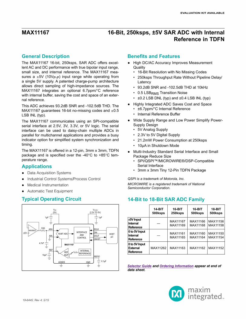
General DescriptionThe MAX11167 16-bit, 250ksps, SAR ADC offers excel-lent AC and DC performance with true bipolar input range, small size, and internal reference. The MAX11167 mea-sures a Q5V (10VP-P) input range while operating from a single 5V supply. A patented charge-pump architecture allows direct sampling of high-impedance sources. The MAX11167 integrates an optional 6.7ppm/NC reference with internal buffer, saving the cost and space of an exter-nal reference.This ADC achieves 93.2dB SNR and -102.5dB THD. The MAX11167 guarantees 16-bit no-missing codes and Q0.5 LSB INL (typ).The MAX11167 communicates using an SPI-compatible serial interface at 2.5V, 3V, 3.3V, or 5V logic. The serial interface can be used to daisy-chain multiple ADCs in parallel for multichannel applications and provides a busy indicator option for simplified system synchronization and timing.The MAX11167 is offered in a 12-pin, 3mm x 3mm, TDFN package and is specified over the -40NC to +85NC tem-perature range.
Applications Data Acquisition Systems
Industrial Control Systems/Process Control
Medical Instrumentation
Automatic Test Equipment
Benefits and Features HighDC/ACAccuracyImprovesMeasurement Quality
• 16-Bit Resolution with No Missing Codes• 250ksps Throughput Rate Without Pipeline Delay/
Latency• 93.2dB SNR and -102.5dB THD at 10kHz• 0.5 LSBRMS Transition Noise• ±0.2 LSB DNL (typ) and ±0.4 LSB INL (typ)
HighlyIntegratedADCSavesCostandSpace• ±6.7ppm/°C Internal Reference • Internal Reference Buffer
WideSupplyRangeandLowPowerSimplifyPower- Supply Design
• 5V Analog Supply• 2.3V to 5V Digital Supply• 21.2mW Power Consumption at 250ksps• 10μAinShutdownMode
Multi-IndustryStandardSerialInterfaceandSmall Package Reduce Size
• SPI/QSPI™/MICROWIRE®/DSP-Compatible Serial Interface
• 3mm x 3mm Tiny 12-Pin TDFN Package
19-6445; Rev 4; 5/15
Typical Operating Circuit
Selector Guide and Ordering Information appear at end of data sheet.
QSPI is a trademark of Motorola, Inc.MICROWIRE is a registered trademark of National Semiconductor Corporation.
14-Bit to 18-Bit SAR ADC Family
14-BIT 500ksps
16-BIT 250ksps
16-BIT 500ksps
18-BIT 500ksps
±5V Input Internal Reference
— MAX11167 MAX11169
MAX11166 MAX11168
MAX11156 MAX11158
0 to 5V Input Internal Reference
— MAX11161MAX11165
MAX11160MAX11164
MAX11150MAX11154
0 to 5V Input External Reference
MAX11262 MAX11163 MAX11162 MAX11152
EVALUATION KIT AVAILABLE
VOVDD(2.3V TO 5V)
VDD (5V)
AIN+
REF
HOSTµC
10µF
4.7nF MAX11167
INTERNAL REFERENCEREF
BUF
GND
16-BIT ADCAIN-
MAX9632INTERFACE
AND CONTROL CNVST
DOUTDINSCLK
1µF1µF
±5V
10Ω
0.1µFAGNDS
REFIO

Maxim Integrated 2
MAX11167 16-Bit, 250ksps, ±5V SAR ADCwith Internal Reference in TDFN
www.maximintegrated.com
VDD to GND ............................................................-0.3V to +6VOVDD to GND ....... -0.3V to the lower of (VDD + 0.3V) and +6VAIN+ to GND ........................................................................ Q7VAIN-, REF, REFIO, AGNDS
to GND ............... -0.3V to the lower of (VDD + 0.3V) and +6VSCLK, DIN, DOUT, CNVST
to GND ............... -0.3V to the lower of (VDD + 0.3V) and +6VMaximum Current into Any Pin...........................................50mA
Continuous Power Dissipation (TA = +70NC) TDFN (derate 18.2mW/NC above +70NC) ..................1349mWOperating Temperature Range ........................... -40NC to +85NCJunction Temperature ......................................................+150NCStorage Temperature Range ............................ -65NC to +150NCLead Temperature (soldering, 10s) .................................+300NCSoldering Temperature (reflow) .......................................+260NC
Absolute Maximum Ratings
Stresses beyond those listed under “Absolute Maximum Ratings” may cause permanent damage to the device. These are stress ratings only, and functional operation of the device at these or any other conditions beyond those indicated in the operational sections of the specifications is not implied. Exposure to absolute maximum rating conditions for extended periods may affect device reliability.
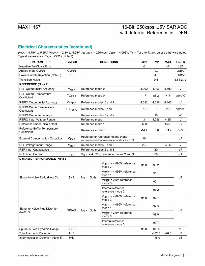
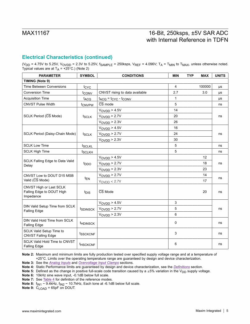
Electrical Characteristics(VDD = 4.75V to 5.25V, VOVDD = 2.3V to 5.25V, fSAMPLE = 250ksps, VREF = 4.096V; TA = TMIN to TMAX, unless otherwise noted. Typical values are at TA = +25NC.) (Note 2)
Note 1: Package thermal resistances were obtained using the method described in JEDEC specification JESD51-7, using a four-layer board. For detailed information on package thermal considerations, refer to www.maximintegrated.com/thermal-tutorial.
TDFN Junction-to-Ambient Thermal Resistance (qJA).......59.3NC/W Junction-to-Case Thermal Resistance (qJC) ...........22.5NC/W
Package Thermal Characteristics (Note 1)
PARAMETER SYMBOL CONDITIONS MIN TYP MAX UNITSANALOG INPUT (Note 3)
Input Voltage Range AIN+ to AIN-, K = -K x VREF +K x VREF V
Absolute Input Voltage RangeAIN+ to GND -(VDD +
0.1)+(VDD +
0.1) VAIN- to GND -0.1 +0.1
Input Leakage Current Acquisition phase -10 +0.001 +10 µA
Input Capacitance 15 pF
Input-Clamp Protection Current Both inputs -20 +20 mASTATIC PERFORMANCEResolution N 16 Bits
No Missing Codes 16 Bits
Offset Error -7.5 ±0.7 +7.5 LSB
Offset Temperature Coefficient ±0.006 LSB/°C
Gain Error -3.5 ±1.6 +3.5 LSB
Gain Error Temperature Coefficient ±0.007 LSB/°C
Integral Nonlinearity INL -1.2 ±0.4 +1.2 LSB
Differential Nonlinearity DNL Guaranteed by design -0.5 ±0.2 +0.5 LSBPositive Full-Scale Error -8 +8 LSB
5.0004.096
Maxim Integrated 3
MAX11167 16-Bit, 250ksps, ±5V SAR ADCwith Internal Reference in TDFN
www.maximintegrated.com
Electrical Characteristics (continued)(VDD = 4.75V to 5.25V, VOVDD = 2.3V to 5.25V, fSAMPLE = 250ksps, VREF = 4.096V; TA = TMIN to TMAX, unless otherwise noted. Typical values are at TA = +25NC.) (Note 2)
PARAMETER SYMBOL CONDITIONS MIN TYP MAX UNITSNegative Full-Scale Error -8 +8 LSBAnalog Input CMRR CMRR -0.9 LSB/VPower-Supply Rejection (Note 5) PSR -4.6 LSB/VTransition Noise 0.5 LSBRMSREFERENCE (Note 7)REF Output Initial Accuracy VREF Reference mode 0 4.092 4.096 4.100 V
REF Output Temperature Coefficient TCREF Reference mode 0 -17 ±8.2 +17 ppm/°C
REFIO Output Initial Accuracy VREFIO Reference modes 0 and 2 4.092 4.096 4.100 V
REFIO Output Temperature Coefficient TCREFIO Reference modes 0 and 2 -15 ±6.7 +15 ppm/°C
REFIO Output Impedance Reference modes 0 and 2 10 kΩREFIO Input Voltage Range Reference mode 1 3 4.096 4.25 VReference Buffer Initial Offset Reference mode 1 -500 +500 µVReference Buffer Temperature Coefficient Reference mode 1 -14.4 ±6.6 +14.4 µV/°C
External Compensation Capacitor CEXTRequired for reference modes 0 and 1, recommended for reference modes 2 and 3 10 µF
REF Voltage Input Range VREF Reference modes 2 and 3 2.5 4.25 VREF Input Capacitance Reference modes 2 and 3 20 pFREF Load Current IREF VREF = 4.096V, reference modes 2 and 3 66 µADYNAMIC PERFORMANCE (Note 6)
Signal-to-Noise Ratio (Note 7) SNR fIN = 10kHz
VREF = 4.096V, reference mode 3 91.8 93.2
dB
VREF = 4.096V, reference mode 1 93.1
VREF = 2.5V, reference mode 3 90.1
Internal reference, reference mode 0 93.2
Signal-to-Noise Plus Distortion (Note 7) SINAD fIN = 10kHz
VREF = 4.096V, reference mode 3 91.0 92.7
dB
VREF = 4.096V, reference mode 1 92.5
VREF = 2.5V, reference mode 3 89.9
Internal reference, reference mode 0 92.7
Spurious-Free Dynamic Range SFDR 98.8 105.8 dBTotal Harmonic Distortion THD -102.5 -96.5 dBIntermodulation Distortion (Note 8) IMD -115.0 dB

Maxim Integrated 4
MAX11167 16-Bit, 250ksps, ±5V SAR ADCwith Internal Reference in TDFN
www.maximintegrated.com
Electrical Characteristics (continued)(VDD = 4.75V to 5.25V, VOVDD = 2.3V to 5.25V, fSAMPLE = 250ksps, VREF = 4.096V; TA = TMIN to TMAX, unless otherwise noted. Typical values are at TA = +25NC.) (Note 2)
PARAMETER SYMBOL CONDITIONS MIN TYP MAX UNITSSAMPLING DYNAMICSThroughput Sample Rate 0.01 250 kspsTransient Response Full-scale step 400 ns
Full-Power Bandwidth-3dB point 6
MHz-0.1dB point > 0.2
Aperture Delay 2.5 nsAperture Jitter < 50 psRMSPOWER SUPPLIESAnalog Supply Voltage VDD 4.75 5.25 V
Interface Supply Voltage VOVDD 2.3 5.25 V
Analog Supply Current IVDDInternal reference mode 5.0 5.8 6.5
mAExternal reference mode 3.0 3.5 4.0
VDD Shutdown Current 6.3 10 µA
Interface Supply Current IOVDDVOVDD = 2.3V 0.8 1.2
mAVOVDD = 5.25V 2.2 2.7
OVDD Shutdown Current 0.9 10 µA
Power Dissipation
VDD = 5V, VOVDD = 3.3V, reference mode = 2, 3 21.2
mWVDD = 5V, VOVDD = 3.3V, reference mode = 0, 1 33.3
DIGITAL INPUTS (DIN, SCLK, CNVST)
Input Voltage High VIH0.7 x
VOVDDV
Input Voltage Low VIL 0.3 x VOVDD V
Input Hysteresis VHYS ±0.05 x VOVDD V
Input Capacitance CIN 10 pF
Input Current IIN VIN = 0V or VOVDD -10 +10 µADIGITAL OUTPUT (DOUT)
Output Voltage High VOH ISOURCE = 2mA VOVDD - 0.4 V
Output Voltage Low VOL ISINK = 2mA 0.4 VThree-State Leakage Current -10 +10 µAThree-State Output Capacitance 15 pF
Maxim Integrated 5
MAX11167 16-Bit, 250ksps, ±5V SAR ADCwith Internal Reference in TDFN
www.maximintegrated.com
Electrical Characteristics (continued)(VDD = 4.75V to 5.25V, VOVDD = 2.3V to 5.25V, fSAMPLE = 250ksps, VREF = 4.096V; TA = TMIN to TMAX, unless otherwise noted. Typical values are at TA = +25NC.) (Note 2)
Note 2: Maximum and minimum limits are fully production tested over specified supply voltage range and at a temperature of +25°C. Limits over the operating temperature range are guaranteed by design and device characterization.
Note 3: See the Analog Inputs and Overvoltage Input Clamps sections.Note 4: Static Performance limits are guaranteed by design and device characterization, see the Definitions section.Note 5: Defined as the change in positive full-scale code transition caused by a Q5% variation in the VDD supply voltage.Note 6: 10kHz sine wave input, -0.1dB below full scale.Note 7: See Table 4 for definition of the reference modes.Note 8: fIN1 ~ 9.4kHz, fIN2 ~ 10.7kHz, Each tone at -6.1dB below full scale.Note 9: CLOAD = 65pF on DOUT.
PARAMETER SYMBOL CONDITIONS MIN TYP MAX UNITSTIMING (Note 9)Time Between Conversions tCYC 4 100000 µs
Conversion Time tCONV CNVST rising to data available 2.7 3.0 µs
Acquisition Time tACQ tACQ = tCYC - tCONV 1 µs
CNVST Pulse Width tCNVPW CS mode 5 ns
SCLK Period (CS Mode) tSCLK
VOVDD > 4.5V 14
nsVOVDD > 2.7V 20
VOVDD > 2.3V 26
SCLK Period (Daisy-Chain Mode) tSCLK
VOVDD > 4.5V 16
nsVOVDD > 2.7V 24
VOVDD > 2.3V 30
SCLK Low Time tSCLKL 5 ns
SCLK High Time tSCLKH 5 ns
SCLK Falling Edge to Data Valid Delay tDDO
VOVDD > 4.5V 12
nsVOVDD > 2.7V 18
VOVDD > 2.3V 23
CNVST Low to DOUT D15 MSB Valid (CS Mode) tEN
VOVDD > 2.7V 14ns
VOVDD < 2.7V 17
CNVST High or Last SCLK Falling Edge to DOUT High Impedance
tDIS CS Mode 20 ns
DIN Valid Setup Time from SCLK Falling Edge tSDINSCK
VOVDD > 4.5V 3
nsVOVDD > 2.7V 5
VOVDD > 2.3V 6
DIN Valid Hold Time from SCLK Falling Edge tHDINSCK 0 ns
SCLK Valid Setup Time to CNVST Falling Edge tSSCKCNF 3 ns
SCLK Valid Hold Time to CNVST Falling Edge tHSCKCNF 6 ns

Maxim Integrated 6www.maximintegrated.com
MAX11167 16-Bit, 250ksps, ±5V SAR ADCwith Internal Reference in TDFN
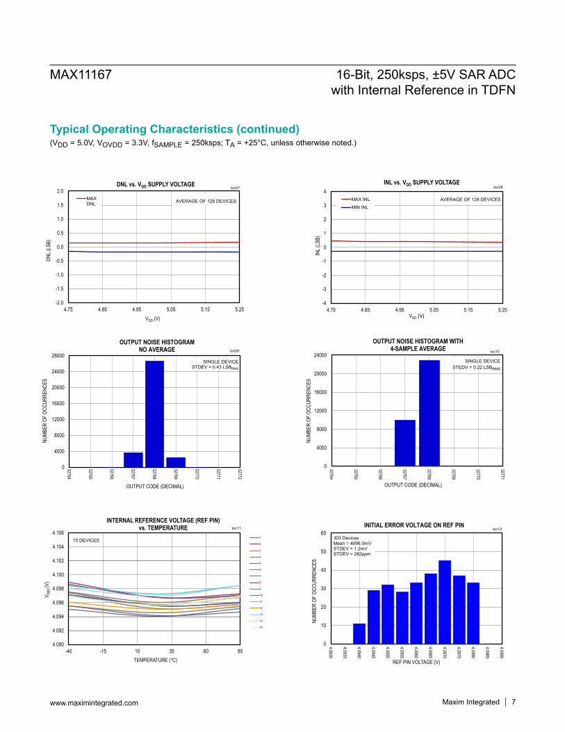
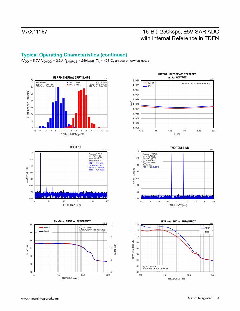
(VDD = 5.0V, VOVDD = 3.3V, fSAMPLE = 250ksps; TA = +25°C, unless otherwise noted.)Typical Operating Characteristics
-4
-3
-2
-1
0
1
2
3
4
-40 -15 10 35 60 85
ERRO
R (L
SB)
TEMPERATURE (°C)
Offset ErrorGain Error
OFFSET AND GAIN ERROR vs. TEMPERATURE
AVERAGE OF 128 DEVICES
toc01
-1.0
-0.8
-0.6
-0.4
-0.2
0.0
0.2
0.4
0.6
0.8
1.0
0 8192
16384
24576
32768
40960
49152
57344
65536
DNL (
LSB)
OUTPUT CODE (DECIMAL)
DIFFERENTIAL NONLINEARITY vs. CODE
SINGLE DEVICE
toc03
-2.0
-1.5
-1.0
-0.5
0.0
0.5
1.0
1.5
2.0
-40 -15 10 35 60 85
DNL
(LSB
)
TEMPERATURE (°C)
DNL vs. TEMPERATURE
MAX DNL
MIN DNLAVERAGE OF 128 DEVICES
toc05
-4
-3
-2
-1
0
1
2
3
4
4.75 4.85 4.95 5.05 5.15 5.25ER
ROR
(LSB
)VDD (V)
Offset ErrorGain Error
OFFSET AND GAIN ERROR vs. VDD SUPPLY VOLTAGE
AVERAGE OF 128 DEVICES
toc02
-2.0
-1.5
-1.0
-0.5
0.0
0.5
1.0
1.5
2.0
0 8192
16384
24576
32768
40960
49152
57344
65536
INL (
LSB)
OUTPUT CODE (DECIMAL)
INTEGRAL NONLINEARITY vs. CODE
SINGLE DEVICE
toc04
-4
-3
-2
-1
0
1
2
3
4
-40 -15 10 35 60 85
INL
(LSB
)
TEMPERATURE (°C)
INL vs. TEMPERATURE
MAX INL
MIN INLAVERAGE OF 128 DEVICES
toc06
Maxim Integrated 7www.maximintegrated.com
MAX11167 16-Bit, 250ksps, ±5V SAR ADCwith Internal Reference in TDFN
(VDD = 5.0V, VOVDD = 3.3V, fSAMPLE = 250ksps; TA = +25°C, unless otherwise noted.)Typical Operating Characteristics (continued)
-2.0
-1.5
-1.0
-0.5
0.0
0.5
1.0
1.5
2.0
4.75 4.85 4.95 5.05 5.15 5.25
DNL (
LSB)
VDD (V)
DNL vs. VDD SUPPLY VOLTAGE
MAXDNL AVERAGE OF 128 DEVICES
toc07
0
4000
8000
12000
16000
20000
24000
28000
32764
32765
32766
32767
32768
32769
32770
32771
32772
NUMB
ER O
F OC
CURR
ENCE
S
OUTPUT CODE (DECIMAL)
OUTPUT NOISE HISTOGRAMNO AVERAGE
SINGLE DEVICESTDEV = 0.43 LSBRMS
toc09
4.090
4.092
4.094
4.096
4.098
4.100
4.102
4.104
4.106
-40 -15 10 35 60 85
V REF
(V)
TEMPERATURE (°C)
INTERNAL REFERENCE VOLTAGE (REF PIN)vs. TEMPERATURE
1
2
3
4
5
6
7
8
9
10
11
12
13
14
15
15 DEVICES
toc11
-4
-3
-2
-1
0
1
2
3
4
4.75 4.85 4.95 5.05 5.15 5.25IN
L (LS
B)VDD (V)
INL vs. VDD SUPPLY VOLTAGE
MAX INL
MIN INL
AVERAGE OF 128 DEVICES
toc08
0
4000
8000
12000
16000
20000
24000
32764
32765
32766
32767
32768
32769
32770
32771
NUMB
ER O
F OC
CURR
ENCE
S
OUTPUT CODE (DECIMAL)
OUTPUT NOISE HISTOGRAM WITH 4-SAMPLE AVERAGE
SINGLE DEVICESTEDV = 0.22 LSBRMS
toc10
0
10
20
30
40
50
60
4.0990
4.0985
4.0980
4.0975
4.0970
4.0965
4.0960
4.0955
4.0950
4.0945
4.0940
4.0935
4.0930
NUMB
ER O
F OC
CURR
ENCE
S
REF PIN VOLTAGE (V)
INITIAL ERROR VOLTAGE ON REF PIN
303 DevicesMean = 4096.0mVSTDEV = 1.2mVSTDEV = 282ppm
toc12
Maxim Integrated 8www.maximintegrated.com
MAX11167 16-Bit, 250ksps, ±5V SAR ADCwith Internal Reference in TDFN
(VDD = 5.0V, VOVDD = 3.3V, fSAMPLE = 250ksps; TA = +25°C, unless otherwise noted.)Typical Operating Characteristics (continued)
0
10
20
30
40
50
60
70
121086420-2-4-6-8-10-12-14-16
NUMB
ER O
F OC
CURR
ENCE
S
THERMAL DRIFT (ppm/°C)
25°C to -40°C25°C to +85°C
REF PIN THERMAL DRIFT SLOPE303 Devices
Mean = 2.1ppm/°CSTDEV = 1.9ppm/°C
303 DevicesMean = -7.3ppm/°C STDEV = 1.9ppm/°C
toc13
-140
-120
-100
-80
-60
-40
-20
0
0 25 50 75 100 125
MAGN
ITUD
E (d
B)
FREQUENCY (kHz)
FFT PLOT
NSAMPLE = 4096fIN = 10101HzVIN = -0.1dBFSRef Mode = 3SNR = 93.1 dBSINAD = 92.4dBSFDR = 103.9dBTHD = -101.65dB
toc15
14.0
14.5
15.0
15.5
16.0
86
88
90
92
94
96
98
0.1 1.0 10.0 100.0
ENOB
(bitS
)
SINA
D (d
B)
FREQUENCY (kHz)
SINAD and ENOB vs. FREQUENCY
SINAD
ENOB
VIN = -0.1dBFSAVERAGE OF 128 DEVICES
toc17
4.0953
4.0954
4.0955
4.0956
4.0957
4.0958
4.0959
4.0960
4.0961
4.0962
4.0963
4.75 4.85 4.95 5.05 5.15 5.25V R
EF(V
)VDD (V)
INTERNAL REFERENCE VOLTAGESvs. VDD VOLTAGE
REFIO
REFAVERAGE OF 200 DEVICES
toc14
-140
-120
-100
-80
-60
-40
-20
0
6.0 7.0 8.0 9.0 10.0 11.0 12.0 13.0 14.0
MAGN
ITUD
E (d
B)
FREQUENCY (kHz)
TWO TONES IMD
NSAMPLE = 32768fIN1 = 9376.5HzVIN1 = -6.1dBFSfIN2 = 10674HzVIN2 = -6.1dBFSSingle DeviceIMD = -126.5dBFS
toc16
80
85
90
95
100
105
110
115
120
0.1 1.0 10.0 100.0
SFDR
AND
-THD
(dB)
FREQUENCY (kHz)
SFDR and -THD vs. FREQUENCY
SFDR
THD
VIN = -0.1dBFSAVERAGE OF 128 DEVICES
toc18

Maxim Integrated 9www.maximintegrated.com
MAX11167 16-Bit, 250ksps, ±5V SAR ADCwith Internal Reference in TDFN
(VDD = 5.0V, VOVDD = 3.3V, fSAMPLE = 250ksps; TA = +25°C, unless otherwise noted.)Typical Operating Characteristics (continued)
86
88
90
92
94
96
98
-40 -15 10 35 60 85
SNR
AND
SINA
D (d
B)
TEMPERATURE (°C)
SNRSINAD
SNR and SINAD vs. TEMPERATURE
fIN = 10kHzVIN = -0.1dBFSAVERAGE OF 128 DEVICES
toc19
86
88
90
92
94
96
98
4.75 4.85 4.95 5.05 5.15 5.25
SNR
AND
SINA
D (d
B)
VDD (V)
SNR
SINAD
SNR and SINAD vs. VDD SUPPLY VOLTAGE
fIN = 10kHzVIN = -0.1dBFSAVERAGE OF 128 DEVICES
toc21
-90
-80
-70
-60
-50
-40
-30
0.1 1.0 10.0 100.0 1000.0
CMR
(dB)
FREQUENCY (kHz)
CMR vs. INPUT FREQUENCY
VAIN+ = VAIN- = ±100mVSINGLE DEVICE
toc23
85
90
95
100
105
110
115
-40 -15 10 35 60 85SF
DR A
ND -T
HD (d
B)TEMPERATURE (°C)
THD
SFDR
SFDR and THD vs. TEMPERATURE
fIN = 10kHzVIN = -0.1dBFSAVERAGE OF 128 DEVICES
toc20
94
96
98
100
102
104
106
108
4.75 4.85 4.95 5.05 5.15 5.25
SFDR
AND
-THD
(dB)
VDD (V)
THD
SFDR
THD AND SFDR vs. VDD SUPPLY VOLTAGE
fIN = 10kHzVIN = -0.1dBFSAVERAGE OF 128 DEVICES
toc22
-80
-70
-60
-50
-40
-30
-20
0.1 1.0 10.0 100.0 1000.0
PSR
(dB)
FREQUENCY (kHz)
PSR vs. VDD SUPPLY FREQUENCY
VVDD= 5.0 ± 250mVVOVDD = 3.3VSINGLE DEVICE
toc24

Maxim Integrated 10www.maximintegrated.com
MAX11167 16-Bit, 250ksps, ±5V SAR ADCwith Internal Reference in TDFN
(VDD = 5.0V, VOVDD = 3.3V, fSAMPLE = 250ksps; TA = +25°C, unless otherwise noted.)Typical Operating Characteristics (continued)
2.0
3.0
4.0
5.0
6.0
7.0
8.0
-40 -15 10 35 60 85
I VDD
(mA)
TEMPERATURE (°C)
VDD SUPPLY CURRENTvs. TEMPERATURE
Ref Mode 0 & 1
Ref Mode 2 & 3AVERAGE OF 128 DEVICES
toc25
2.0
3.0
4.0
5.0
6.0
7.0
8.0
4.75 4.85 4.95 5.05 5.15 5.25
I VDD
(mA)
VDD (V)
VDD SUPPLY CURRENTvs. VDD SUPPLY VOLTAGE
Ref Mode 0 & 1
Ref Mode 2 & 3AVERAGE OF 128 DEVICES
toc27
0
2
4
6
8
10
-40 -15 10 35 60 85
SHUT
DOW
N CU
RREN
T (µ
A)
TEMPERATURE (°C)
VDD AND OVDD SHUTDOWNCURRENT vs. TEMPERATURE
IVDD
IOVDDAVERAGE OF 128 DEVICES
toc29
0.0
0.5
1.0
1.5
2.0
-40 -15 10 35 60 85I OV
DD(m
A)TEMPERATURE (°C)
OVDD SUPPLY CURRENTvs. TEMPERATURE
250ksps10ksps
CDOUT = 65pFAVERAGE OF 128 DEVICES
toc26
0
1
2
3
4
2.25 2.75 3.25 3.75 4.25 4.75 5.25
I OVDD
(mA)
VOVDD (V)
OVDD SUPPLY CURRENT vs. OVDD SUPPLY VOLTAGE
250ksps10ksps
CDOUT = 65pFAVERAGE OF 128 DEVICES
toc28
0
2
4
6
8
10
2.25 2.75 3.25 3.75 4.25 4.75 5.25
SHUT
DOW
N CU
RREN
T (µ
A)
VDD or VOVDD (V)
VDD AND OVDD SHUTDOWNCURRENT vs. SUPPLY VOLTAGE
IVDD
IOVDD
AVERAGE OF 128 DEVICES
toc30
Maxim Integrated 11
MAX11167 16-Bit, 250ksps, ±5V SAR ADCwith Internal Reference in TDFN
www.maximintegrated.com
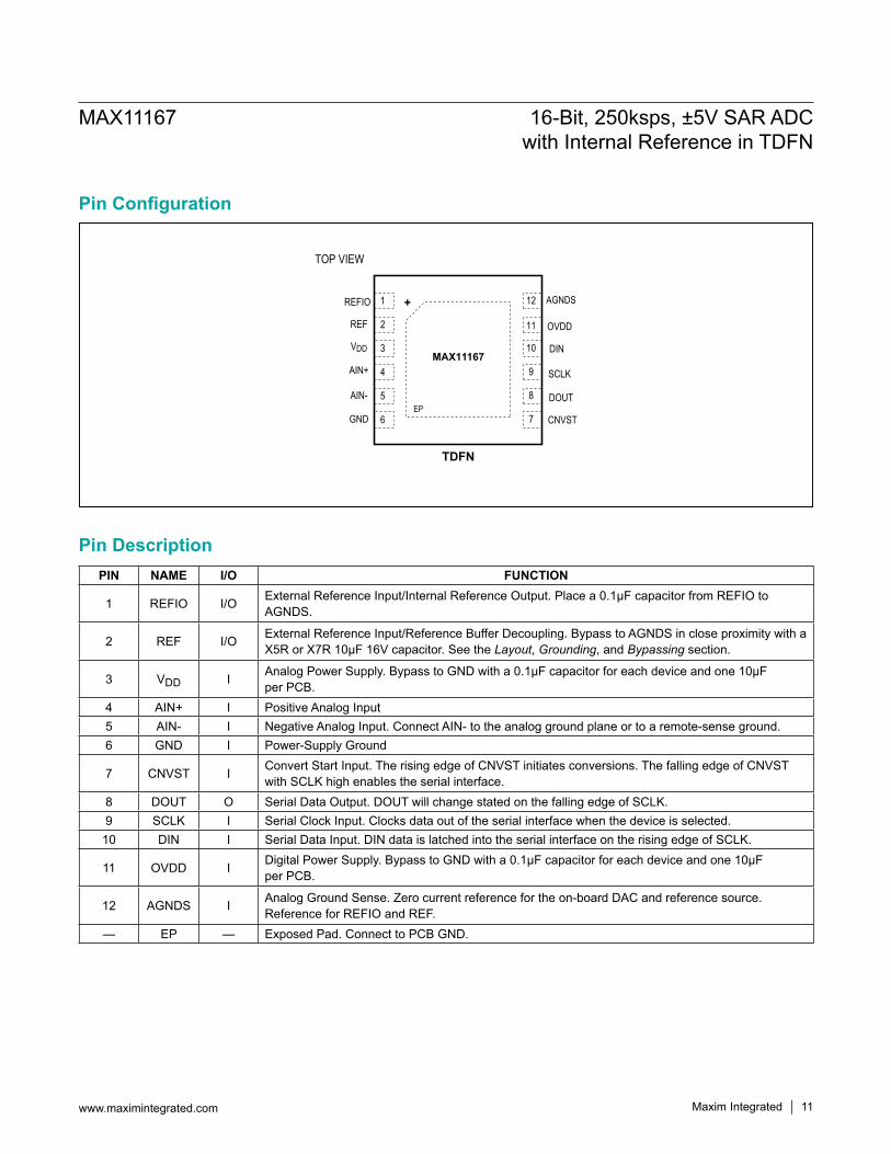
Pin Configuration
Pin DescriptionPIN NAME I/O FUNCTION
1 REFIO I/O External Reference Input/Internal Reference Output. Place a 0.1µF capacitor from REFIO to AGNDS.
2 REF I/O External Reference Input/Reference Buffer Decoupling. Bypass to AGNDS in close proximity with a X5R or X7R 10µF 16V capacitor. See the Layout, Grounding, and Bypassing section.
3 VDD I Analog Power Supply. Bypass to GND with a 0.1µF capacitor for each device and one 10µF per PCB.
4 AIN+ I Positive Analog Input5 AIN- I Negative Analog Input. Connect AIN- to the analog ground plane or to a remote-sense ground.6 GND I Power-Supply Ground
7 CNVST I Convert Start Input. The rising edge of CNVST initiates conversions. The falling edge of CNVST with SCLK high enables the serial interface.
8 DOUT O Serial Data Output. DOUT will change stated on the falling edge of SCLK.9 SCLK I Serial Clock Input. Clocks data out of the serial interface when the device is selected.
10 DIN I Serial Data Input. DIN data is latched into the serial interface on the rising edge of SCLK.
11 OVDD I Digital Power Supply. Bypass to GND with a 0.1µF capacitor for each device and one 10µF per PCB.
12 AGNDS I Analog Ground Sense. Zero current reference for the on-board DAC and reference source. Reference for REFIO and REF.
— EP — Exposed Pad. Connect to PCB GND.
1
3
4
12
10
9
8
AGNDS
DIN
SCLK
DOUT
MAX11167
2 11 OVDD
5
6
+
7 CNVST
REFIO
VDD
AIN+
AIN-
REF
GNDEP
TDFN
TOP VIEW
Maxim Integrated 12
MAX11167 16-Bit, 250ksps, ±5V SAR ADCwith Internal Reference in TDFN
www.maximintegrated.com
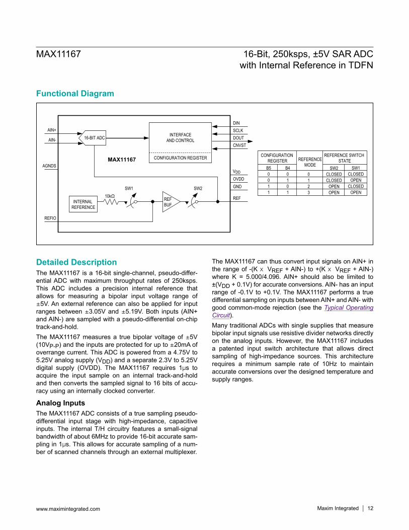
Functional Diagram
Detailed DescriptionThe MAX11167 is a 16-bit single-channel, pseudo-differ-ential ADC with maximum throughput rates of 250ksps. This ADC includes a precision internal reference that allows for measuring a bipolar input voltage range of Q5V. An external reference can also be applied for input ranges between Q3.05V and Q5.19V. Both inputs (AIN+ and AIN-) are sampled with a pseudo-differential on-chip track-and-hold.The MAX11167 measures a true bipolar voltage of Q5V (10VP-P) and the inputs are protected for up to Q20mA of overrange current. This ADC is powered from a 4.75V to 5.25V analog supply (VDD) and a separate 2.3V to 5.25V digital supply (OVDD). The MAX11167 requires 1Fs to acquire the input sample on an internal track-and-hold and then converts the sampled signal to 16 bits of accu-racy using an internally clocked converter.
Analog InputsThe MAX11167 ADC consists of a true sampling pseudo-differential input stage with high-impedance, capacitive inputs. The internal T/H circuitry features a small-signal bandwidth of about 6MHz to provide 16-bit accurate sam-pling in 1Fs. This allows for accurate sampling of a num-ber of scanned channels through an external multiplexer.
The MAX11167 can thus convert input signals on AIN+ in the range of -(K O VREF + AIN-) to +(K O VREF + AIN-) where K = 5.000/4.096. AIN+ should also be limited to ±(VDD + 0.1V) for accurate conversions. AIN- has an input range of -0.1V to +0.1V. The MAX11167 performs a true differential sampling on inputs between AIN+ and AIN- with good common-mode rejection (see the Typical Operating Circuit). Many traditional ADCs with single supplies that measure bipolar input signals use resistive divider networks directly on the analog inputs. However, the MAX11167 includes a patented input switch architecture that allows direct sampling of high-impedance sources. This architecture requires a minimum sample rate of 10Hz to maintain accurate conversions over the designed temperature and supply ranges.
16-BIT ADC
CONFIGURATION REGISTER
REFBUFINTERNAL
REFERENCE
AIN+
AIN-
AGNDS
SW110kΩ
REFIO
CNVSTDOUT
REF
GNDOVDDVDD
SCLKDIN
INTERFACEAND CONTROL
MAX11167
SW2
CONFIGURATION REGISTER REFERENCE
MODE
REFERENCE SWITCH STATE
B50011
B40101
SW2CLOSEDCLOSED
OPENOPEN
SW1CLOSED
OPENCLOSED
OPEN
0123
Maxim Integrated 13
MAX11167 16-Bit, 250ksps, ±5V SAR ADCwith Internal Reference in TDFN
www.maximintegrated.com
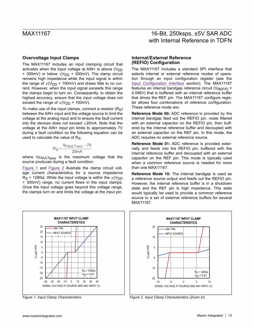
Overvoltage Input ClampsThe MAX11167 includes an input clamping circuit that activates when the input voltage at AIN+ is above (VDD + 300mV) or below -(VDD + 300mV). The clamp circuit remains high impedance while the input signal is within the range of Q(VDD + 100mV) and draws little to no cur-rent. However, when the input signal exceeds this range the clamps begin to turn on. Consequently, to obtain the highest accuracy, ensure that the input voltage does not exceed the range of Q(VDD + 100mV).To make use of the input clamps, connect a resistor (RS) between the AIN+ input and the voltage source to limit the voltage at the analog input and to ensure the fault current into the devices does not exceed Q20mA. Note that the voltage at the AIN+ input pin limits to approximately 7V during a fault condition so the following equation can be used to calculate the value of RS:
MAXFAULTS
V 7VR
20mA
−=
where VFAULTMAX is the maximum voltage that the source produces during a fault condition.Figure 1 and Figure 2 illustrate the clamp circuit volt-age current characteristics for a source impedance RS = 1280I. While the input voltage is within the Q(VDD + 300mV) range, no current flows in the input clamps. Once the input voltage goes beyond this voltage range, the clamps turn on and limits the voltage at the input pin.
Internal/External Reference (REFIO) ConfigurationThe MAX11167 includes a standard SPI interface that selects internal or external reference modes of opera-tion through an input configuration register (see the Input Configuration Interface section). The MAX11167 features an internal bandgap reference circuit (VREFIO = 4.096V) that is buffered with an internal reference buffer that drives the REF pin. The MAX11167 configure regis-ter allows four combinations of reference configuration. These reference mode are:Reference Mode 00: ADC reference is provided by the internal bandgap feed out the REFIO pin, noise filtered with an external capacitor on the REFIO pin, then buff-ered by the internal reference buffer and decoupled with an external capacitor on the REF pin. In this mode, the ADC requires no external reference source.Reference Mode 01: ADC reference is provided exter-nally and feeds into the REFIO pin, buffered with the internal reference buffer and decoupled with an external capacitor on the REF pin. This mode is typically used when a common reference source is needed for more than one MAX11167.Reference Mode 10: The internal bandgap is used as a reference source output and feeds out the REFIO pin. However, the internal reference buffer is in a shutdown state and the REF pin is high impedance. This state would typically be used to provide a common reference source to a set of external reference buffers for several MAX11167.
Figure 1. Input Clamp Characteristics Figure 2. Input Clamp Characteristics (Zoom In)
MAX11167 INPUT CLAMPCHARACTERISTICS
SIGNAL VOLTAGE AT SOURCE AND AIN+ INPUT (V)
I CLA
MP (m
A)
30200 10-20 -10-30
-20
-15
-10
-5
0
5
10
15
20
25
-25-40 40
RS = 1280IVDD = 5.0V
AIN+ PININPUT SOURCE
MAX11167 INPUT CLAMPCHARACTERISTICS
SIGNAL VOLTAGE AT SOURCE AND AIN+ INPUT (V)
I CLA
MP (m
A)
50-5
-15
-5
5
15
25
-25-10 10
RS = 1280IVDD = 5.0V
AIN+ PININPUT SOURCE

Maxim Integrated 14
MAX11167 16-Bit, 250ksps, ±5V SAR ADCwith Internal Reference in TDFN
www.maximintegrated.com
Reference Mode 11: The internal bandgap reference source as well as the internal reference buffer are both in a shutdown state. The REF pin is in a high-impedance state. This mode would typically be used when an exter-nal reference source and external reference buffer is used to drive all MAX11167 parts in a system.Regardless of the reference mode used, the MAX11167 requires a low-impedance reference source on the REF pin to support 16-bit accuracy. When using the internal reference buffer, externally bypass the reference buffer output using at least a 10FF, low-inductance, low-ESR capacitor placed as close as possible to the REF pin, thus minimizing additional PCB inductance. When using the internal bandgap reference source, bypass the REFIO pin with a 0.1FF capacitor to ground. If providing an external reference and using the internal reference buffer, drive the REFIO pin directly with an external reference source in the range of 3.0V to 4.25V. Finally, if disabling the MAX11167 internal bandgap reference source and inter-nal reference buffer, drive the REF pin with a reference voltage in the range of 2.5V to 4.25V and place at least a 10FF, low-inductance, low-ESR capacitor as close as possible to the REF pin.When using the MAX11167 in external reference mode, it is recommended that an external reference buffer be used. For bypass capacitors on the REF pin, X7R or X5R ceramic capacitors in a 1210 case size or smaller have been found to provide adequate bypass performance. Y5U or Z5U ceramic capacitors are not recommended due to their high voltage and temperature coefficients.Maxim Integrated offers a wide range of precision refer-ences ideal for 16-bit accuracy. Table 1 lists some of the options recommended.
Input AmplifierThe conversion results are accurate when the ADC acquires the input signal for an interval longer than the input signal's worst-case settling time. The ADC input sampling capacitor charges during the acquisition period.
During this acquisition period, the settling of the sampled voltage is affected by the source resistance and the input sampling capacitance. Sampling error can be estimated by modeling the time constant of the total input capaci-tance and the driving source impedance. Although the MAX11167 is easy to drive, an amplifier buf-fer is recommended if the source impedance is such that when driving a switch capacitor of ~20pF a significant settling error in the desired sampling period will occur. If this is the case, it is recommended that a configuration shown in the Typical Operating Circuit is used where at least a 500pF capacitor is attached to the AIN+ pin. This capacitance reduces the size of the transient at the start of the acquisition period, which in some buffers will cause an input signal dependent offsets.Regardless of whether an external buffer amp is used or not, the time constant, RSOURCE × CLOAD, of the input should not exceed tACQ/12, where RSOURCE is the total signal source impedance, CLOAD is the total capacitance at the ADC input (external and internal), and tACQ is the acquisition period. Thus, to obtain accurate sampling in a 500ns acquisition time, a source impedance of less than 1042ΩshouldbeusedifdirectlydrivingtheADC.Whendriving the ADC from a buffer, it is recommended to place aseriesresistance(5Ωto50Ωtypical)betweentheampli-fier and the external input capacitance as shown in the Typical Operating Circuit.1) Fast settling time: For multichannel multiplexed appli-
cations, the driving operational amplifier must be able to settle to 16-bit resolution when a full-scale step is applied during the minimum acquisition time.
2) Low noise: It is important to ensure that the driver amplifier has a low average noise density appropriate for the desired bandwidth of the application. When the MAX11167 is used with its full bandwidth of 6MHz, it is preferable to use an amplifier that will produce an output noise spectral density of less than 6nV/√Hz, to ensure that the overall SNR is not degraded sig-nificantly. It is recommended to insert an external RC
Table 1. MAX11167 External Reference Recommendations
PART VOUT (V) TEMPERATURE COEFFICIENT (MAX)
INITIAL ACCURACY (%)
NOISE (0.1Hz TO 10Hz) (µVP-P) PACKAGE
MAX6126 2.5, 3, 4.096, 5.0 3 (A), 5 (B) 0.06 1.35 µMAX-8SO-8
MAX6325MAX6341MAX6350
2.5, 4.096, 5.0 1 0.04, 0.02 1.5, 2.4, 3.0 SO-8
Maxim Integrated 15
MAX11167 16-Bit, 250ksps, ±5V SAR ADCwith Internal Reference in TDFN
www.maximintegrated.com
filter at the MAX11167 AIN+ input to attenuate out-of-band input noise and preserve the ADC's SNR. The effective RMS noise at the MAX11167 AIN+ input is 64FV, thus additional noise from a buffer circuit should be significantly lower to achieve the maximum SNR performance.
3) THD performance: The input buffer amplifier used should have a comparable THD performance with that of the MAX11167 to ensure the THD of the digitized signal is not degraded.
Table 2 summarizes the operational amplifiers that are compatible with the MAX11167. The MAX9632 has suf-ficient bandwidth as well as low enough noise and distor-tion to support the full performance of the MAX11167. The MAX9633 is a dual amp and can support buffering for true pseudo-differential sampling.
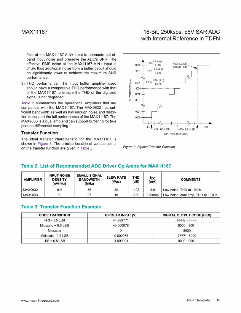
Transfer FunctionThe ideal transfer characteristic for the MAX11167 is shown in Figure 3. The precise location of various points on the transfer function are given in Table 3.
Table 2. List of Recommended ADC Driver Op Amps for MAX11167
Figure 3. Bipolar Transfer Function
Table 3. Transfer Function Example
AMPLIFIERINPUT-NOISE
DENSITY (nV/√Hz)
SMALL-SIGNAL BANDWIDTH
(MHz)
SLEW RATE (V/µs)
THD (dB)
ICC (mA) COMMENTS
MAX9632 0.9 55 30 -128 3.9 Low noise, THD at 10kHzMAX9633 3 27 18 -130 3.5/amp Low noise, dual amp, THD at 10kHz
CODE TRANSITION BIPOLAR INPUT (V) DIGITAL OUTPUT CODE (HEX)+FS - 1.5 LSB +4.999771 FFFE - FFFF
Midscale + 0.5 LSB +0.000076 8000 - 8001Midscale 0 8000
Midscale - 0.5 LSB -0.000076 7FFF - 8000-FS + 0.5 LSB -4.999924 0000 - 0001
-FS
FFFF
8001
8000
0000
0001
7FFEOUTP
UTCO
DE (h
ex)
INPUT VOLTAGE (LSB)
7FFF
0
FULL-SCALETRANSITION
-FS
FFFE
-FS + 0.5 × LSB +FS - 1.5 × LSB
+FS = 5 x VREF
4.096
LSB = +FS - (-FS)
65536
-FS = -5 x VREF
4.096

Maxim Integrated 16
MAX11167 16-Bit, 250ksps, ±5V SAR ADCwith Internal Reference in TDFN
www.maximintegrated.com
Input Configuration InterfaceAn SPI interface clocked at up to 50MHz controls the MAX11167. Input configuration data is clocked into the configuration register on the falling edge of SCLK through the DIN pin. The data on DIN is used to program the ADC configuration register. The construct of this register is illustrated in Table 4. The configuration register defines the output interface mode, the reference mode, and the power-down state of the MAX11167.
Configuring in CS ModeFigure 4 details the timing for loading the input configura-tion register when the MAX11167 is connected in CS mode (see Figure 6 and Figure 8 for hardware connections). The load process is enabled on the falling edge of CNVST when SCLK is held high. The configuration data is clocked into the configuration register through DIN on the next 8 SCLK falling edges. Pull CNVST high to complete the input configuration register load process. DIN should idle high outside an input configuration register read.
Table 4. ADC Configuration Register
Figure 4. Input Configuration Timing in CS Mode
BIT NAME BIT DEFAULT STATE
LOGIC STATE FUNCTION
MODE 7:6 00
00 CS Mode, No-Busy Indicator01 CS Mode, with Busy Indicator10 Daisy-Chain Mode, No-Busy Indicator11 Daisy-Chain Mode, with Busy Indicator
REF 5:4 00
00 Reference Mode 0. Internal reference and reference buffer are both powered on.
01 Reference Mode 1. Internal reference is turned off, but internal reference buffer powered on. Apply the external reference voltage at REFIO.
10Reference Mode 2. Internal reference is powered on, but the internal reference buffer is powered off. This mode allows for internal reference to be used with an external reference buffer.
11 Reference Mode 3. Internal reference and reference buffer are both powered off. Apply an external reference voltage at REF.
SHDN 3 00 Normal Mode. All circuitry is fully powered up at all times.1 Static Shutdown. All circuitry is powered down.
Reserved 2:0 0 0 Reserved, Set to 0
0 1 2 3 4 5 6 7
tHSCKCNF
tSSCKCNF
CNVST
SCLK
DIN
tHDINSCK tSDINSCK
B6 B5 B4 B3 B2 B1 B0B7
Maxim Integrated 17
MAX11167 16-Bit, 250ksps, ±5V SAR ADCwith Internal Reference in TDFN
www.maximintegrated.com
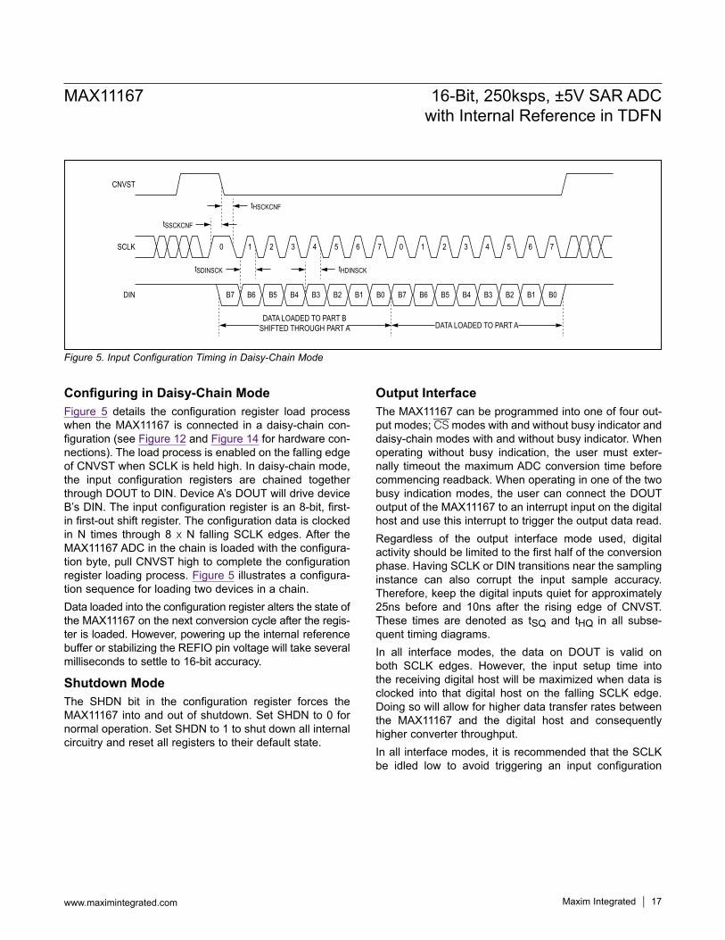
Configuring in Daisy-Chain ModeFigure 5 details the configuration register load process when the MAX11167 is connected in a daisy-chain con-figuration (see Figure 12 and Figure 14 for hardware con-nections). The load process is enabled on the falling edge of CNVST when SCLK is held high. In daisy-chain mode, the input configuration registers are chained together through DOUT to DIN. Device A’s DOUT will drive device B’s DIN. The input configuration register is an 8-bit, first-in first-out shift register. The configuration data is clocked in N times through 8 O N falling SCLK edges. After the MAX11167 ADC in the chain is loaded with the configura-tion byte, pull CNVST high to complete the configuration register loading process. Figure 5 illustrates a configura-tion sequence for loading two devices in a chain.Data loaded into the configuration register alters the state of the MAX11167 on the next conversion cycle after the regis-ter is loaded. However, powering up the internal reference buffer or stabilizing the REFIO pin voltage will take several milliseconds to settle to 16-bit accuracy.
Shutdown ModeThe SHDN bit in the configuration register forces the MAX11167 into and out of shutdown. Set SHDN to 0 for normal operation. Set SHDN to 1 to shut down all internal circuitry and reset all registers to their default state.
Output InterfaceThe MAX11167 can be programmed into one of four out-put modes; CS modes with and without busy indicator and daisy-chain modes with and without busy indicator. When operating without busy indication, the user must exter-nally timeout the maximum ADC conversion time before commencing readback. When operating in one of the two busy indication modes, the user can connect the DOUT output of the MAX11167 to an interrupt input on the digital host and use this interrupt to trigger the output data read.Regardless of the output interface mode used, digital activity should be limited to the first half of the conversion phase. Having SCLK or DIN transitions near the sampling instance can also corrupt the input sample accuracy. Therefore, keep the digital inputs quiet for approximately 25ns before and 10ns after the rising edge of CNVST. These times are denoted as tSQ and tHQ in all subse-quent timing diagrams.In all interface modes, the data on DOUT is valid on both SCLK edges. However, the input setup time into the receiving digital host will be maximized when data is clocked into that digital host on the falling SCLK edge. Doing so will allow for higher data transfer rates between the MAX11167 and the digital host and consequently higher converter throughput. In all interface modes, it is recommended that the SCLK be idled low to avoid triggering an input configuration
Figure 5. Input Configuration Timing in Daisy-Chain Mode
B7 B6 B5 B4 B3 B2 B1 B0 B7 B6 B5 B4 B3 B2 B1 B0
tHSCKCNF
tSDINSCK tHDINSCK
DATA LOADED TO PART BSHIFTED THROUGH PART A DATA LOADED TO PART A
tSSCKCNF
CNVST
0 1 2 3 4 5 6 7 0 1 2 3 4 5 6 7SCLK
DIN

Maxim Integrated 18
MAX11167 16-Bit, 250ksps, ±5V SAR ADCwith Internal Reference in TDFN
www.maximintegrated.com
write on the falling edge of CNVST. If at anytime the device detects a high SCLK state on a falling edge of CNVST, it will enter the input configuration write mode and will write the state of DIN on the next 8 falling SCLK edges to the input configuration register.In all interface modes, all data bits from a previous conver-sion must be read before reading bits from a new conver-sion. When reading out conversion data, if too few SCLK falling edges are provided and all data bits are not read out, only the remaining unread data bits will be outputted during the next readout cycle. In such an event, the output data in every other readout cycle will appear to have been trun-cated as only the leftover bits from the previous readout cycle are outputted. This is an indication to the user that there are insufficient SCLK falling edges in a given readout cycle. Table 5 provides a guide to aid in the selection of the appropriate output interface mode for a given application.
CS No-Busy Indicator ModeThe CS no-busy indicator mode is ideally suited for maxi-mum throughput when a single MAX11167 is connected to an SPI-compatible digital host. The connection diagram is shown in Figure 6, and the corresponding timing is pro-vided in Figure 7. A rising edge on CNVST completes the acquisition, initi-ates the conversion, and forces DOUT to high impedance. The conversion continues to completion irrespective of the state of CNVST allowing CNVST to be used as a select line for other devices on the board. If CNVST is brought low during a conversion and held low throughout the maximum conversion time, the MSB will be output at the end of the conversion.When the conversion is complete, the MAX11167 enters the acquisition phase. Drive CNVST low to output the MSB onto DOUT. The remaining data bits are then clocked by subsequent SCLK falling edges. DOUT returns to high impedance after the 16th SCLK falling edge, or when CNVST goes high.
Table 5. ADC Output Interface Mode Selector Guide
Figure 6. CS No-Busy Indicator Mode Connection Diagram
MODE TYPICAL APPLICATION AND BENEFITS
CS Mode, No-Busy Indicator
Single or multiple ADCs connected to an SPI-compatible digital host. Ideally suited for maximum throughput.
CS Mode, With Busy Indicator
Single ADC connected to an SPI-compatible digital host with interrupt input. Ideally suited for maximum throughput.
Daisy-Chain Mode, No-Busy Indicator
Multiple ADCs connected to an SPI-compatible digital host. Ideally suited for multichannel simultaneous sampled isolated applications.
Daisy-Chain Mode, With Busy Indicator
Multiple ADCs connected to an SPI-compatible digital host with interrupt input. Ideally suited for multichannel simultaneous sampled isolated applications.
CLK
DATA IN
DIGITAL HOST
CONVERT
CONFIG
DOUT
SCLK
CNVST
DIN
MAX11167
Maxim Integrated 19
MAX11167 16-Bit, 250ksps, ±5V SAR ADCwith Internal Reference in TDFN
www.maximintegrated.com
Figure 7. CS No Busy Indicator Mode Timing
Figure 8. CS With Busy Indicator Mode Connection Diagram
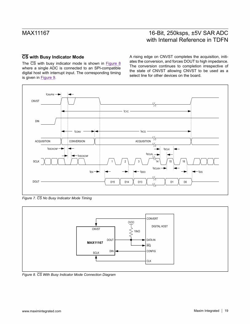
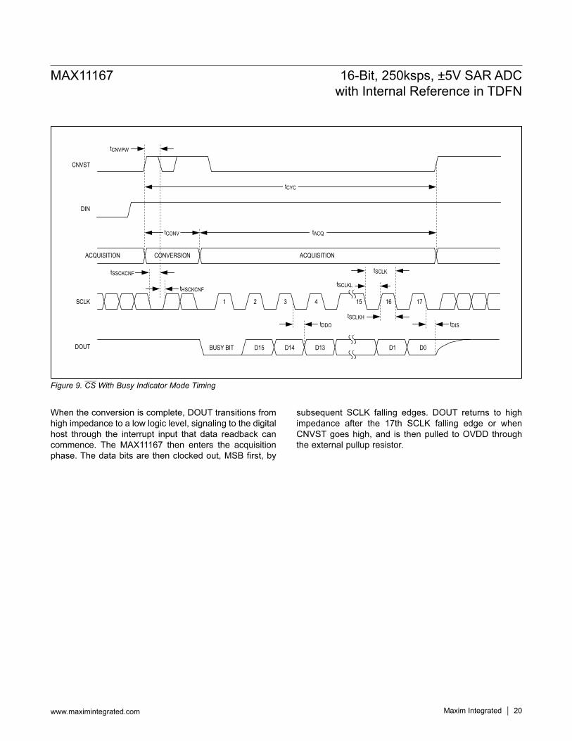
CS with Busy Indicator ModeThe CS with busy indicator mode is shown in Figure 8 where a single ADC is connected to an SPI-compatible digital host with interrupt input. The corresponding timing is given in Figure 9.
A rising edge on CNVST completes the acquisition, initi-ates the conversion, and forces DOUT to high impedance. The conversion continues to completion irrespective of the state of CNVST allowing CNVST to be used as a select line for other devices on the board.
tCONV tACQ
DIN
ACQUISITION
SCLK
DOUT
CONVERSION ACQUISITION
1 2 3 14 15 16
tDDOtENtSCLKH
tSCLKLtHSCKCNF
tSSCKCNF
D15 D14 D13 D1 D0
CNVST
tCNVPW
tCYC
tSCLK
tDIS
CLK
DATA IN
IRQ
OVDD
10kΩDIGITAL HOST
CONVERT
CONFIG
DOUT
SCLK
CNVST
DIN
MAX11167
Maxim Integrated 20
MAX11167 16-Bit, 250ksps, ±5V SAR ADCwith Internal Reference in TDFN
www.maximintegrated.com
Figure 9. CS With Busy Indicator Mode Timing
When the conversion is complete, DOUT transitions from high impedance to a low logic level, signaling to the digital host through the interrupt input that data readback can commence. The MAX11167 then enters the acquisition phase. The data bits are then clocked out, MSB first, by
subsequent SCLK falling edges. DOUT returns to high impedance after the 17th SCLK falling edge or when CNVST goes high, and is then pulled to OVDD through the external pullup resistor.
tCNVPW
D14D15BUSY BITDOUT
SCLK
ACQUISITION ACQUISITIONCONVERSION
DIN
CNVST
D13 D1 D0
1 2 3 4 15 16 17
tCONV tACQ
tCYC
tSCLKL
tSCLK
tDDOtSCLKH
tDIS
tHSCKCNF
tSSCKCNF

Maxim Integrated 21
MAX11167 16-Bit, 250ksps, ±5V SAR ADCwith Internal Reference in TDFN
www.maximintegrated.com
Multichannel CS Configuration, Asynchronous or Simultaneous SamplingThe multichannel CS configuration is generally used when multiple MAX11167 ADCs are connected to an SPI-compatible digital host. Figure 10 shows the connection diagram example using two MAX11167 devices. Figure 11 shows the corresponding timing.Asynchronous or simultaneous sampling is possible by controlling the CS1 and CS2 edges. In Figure 10, the DOUT bus is shared with the digital host limiting the throughput rate. However, maximum throughput is possible if the host accommodates each ADC’s DOUT pin independently.A rising edge on CNVST completes the acquisition, initiates the conversion and forces DOUT to high impedance. The conversion continues to completion irrespective of the state of CNVST allowing CNVST
to be used as a select line for other devices on the board. However, CNVST must be returned high before the minimum conversion time for proper operation so that another conversion is not initiated with insufficient acquisition time and data correctly read out of the device.When the conversion is complete, the MAX11167 enters the acquisition phase. Each ADC result can be read by bringing its CNVST input low, which consequently outputs the MSB onto DOUT. The remaining data bits are then clocked by subsequent SCLK falling edges. For each device, its DOUT will return to a high-impedance state after the 16th SCLK falling edge or when CNVST goes high. This control allows multiple devices to share the same DOUT bus.
Figure 10. Multichannel CS Configuration Diagram
MAX11167MAX11167
CLK
DATA IN
DIGITAL HOST
CS2CS1
CONFIG
DOUT
SCLKDEVICE B
CNVST
SCLKDEVICE A
CNVST
DIN
DOUT
DIN

Maxim Integrated 22
MAX11167 16-Bit, 250ksps, ±5V SAR ADCwith Internal Reference in TDFN
www.maximintegrated.com
Figure 11. Multichannel CS Configuration Timing
Daisy-Chain, No-Busy Indicator ModeThe daisy-chain mode with no-busy indicator is ideally suited for multichannel isolated applications that require minimal wiring complexity. Simultaneous sampling of multiple ADC channels is realized on the serial inter-face where data readback is analogous to clocking a shift register. Figure 12 shows a connection diagram of two MAX11167s configured in a daisy chain. The corre-sponding timing is given in Figure 13.A rising edge on CNVST completes the acquisition and initiates the conversion. Once a conversion is initiated, it continues to completion irrespective of the state of CNVST. When a conversion is complete, the MSB is presented onto DOUT and the MAX11167 returns to the acquisition phase. The remaining data bits are stored within an internal shift register. To read these bits out, CNVST is brought low and each bit is shifted out on sub-sequent SCLK falling edge. The DIN input of each ADC in the chain is used to transfer conversion data from the previous ADC into the internal shift register of the next ADC, thus allowing for data to be clocked through the multichip chain on each SCLK falling edge. Each ADC
in the chain outputs its MSB data first requiring 16 × N clocks to read back N ADCs.In daisy-chain mode, the maximum conversion rate is reduced due to the increased readback time. For instance, with a 6ns or less digital host setup time and 3V interface, up to four MAX11167 devices run at a con-version rate of 218ksps.
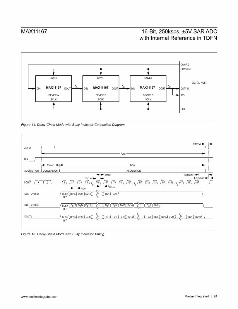
Daisy-Chain with Busy Indicator ModeThe daisy-chain mode with busy indicator is ideally suited for multichannel isolated applications that require minimal wiring complexity while providing a conversion complete indication that can be used to interrupt a host processor to read data.Simultaneous sampling of multiple ADC channels is real-ized on the serial interface where data readback is analo-gous to clocking a shift register. The daisy-chain mode with busy indicator is shown in Figure 14 where three MAX11167s are connected to an SPI-compatible digital host with corresponding timing given in Figure 15.
CNVSTA(CS1)
CNVSTB(CS2)
1 2 3 15 16
tCONV
CONVERSION ACQUISITION
tCYC
D15 D14 D13 D1 D0
tSCLKL
tSCLKHtEN
tDIStDDO
tSCLK
DOUT
ACQUISITION
SCLK
D15 D14 D1 D0
3217 18 31
tEN
D13
19
tDIS
tCNVPW tCNVPW
DIN
tACQ
tHSCKCNFtSSCKCNF

Maxim Integrated 23
MAX11167 16-Bit, 250ksps, ±5V SAR ADCwith Internal Reference in TDFN
www.maximintegrated.com
Figure 13. Daisy-Chain, No-Busy Indicator Mode Timing
Figure 12. Daisy-Chain, No-Busy Indicator Mode Connection Diagram
A rising edge on CNVST completes the acquisition and initiates the conversion. Once a conversion is initiated, it continues to completion irrespective of the state of CNVST. When a conversion is complete, the busy indicator is pre-sented onto each DOUT and the MAX11167 returns to the acquisition phase. The busy indicator for the last ADC in the chain is connected to an interrupt input on the digital host. The digital host should insert a 50ns delay from the receipt of this interrupt before reading out data from all ADCs to ensure that all devices in the chain have com-pleted conversion.
The conversion data is stored within an internal shift reg-ister. To read these bits out, CNVST is brought low and each bit is shifted out on a subsequent SCLK falling edge. The DIN input of each ADC in the chain is used to transfer conversion data from the previous ADC into the internal shift register of the next ADC, thus allowing for data to be clocked through the multichip chain on each SCLK falling edge. The total of number of falling SCLKs needed to read back all data from N ADCs is 16 × N + 1 edges, the one additional SCLK falling edge required to clock out the busy mode bit from the host side ADC.
MAX11167MAX11167
CLK
DATA IN
DIGITAL HOST
CONFIG
CONVERT
SCLKDEVICE B
CNVST
SCLKDEVICE A
CNVST
DOUTDBDINDIN DOUT
DA
SCLK 1 2 3 15 16
CNVST
tCONV
CONVERSIONACQUISITION ACQUISITION
tACQ
tSCLKtSCLKL
tSCLKHtDDO
30 31 3217 18
DOUTB DB15 DB14 DB13 DB1 DB0 DA15 DA14 DA1 DA0
tCNVPW
DIN
tCYC
14tHSCKCNF
tSSCKCNF
Maxim Integrated 24
MAX11167 16-Bit, 250ksps, ±5V SAR ADCwith Internal Reference in TDFN
www.maximintegrated.com
Figure 15. Daisy-Chain Mode with Busy Indicator Timing
Figure 14. Daisy-Chain Mode with Busy Indicator Connection Diagram
MAX11167 MAX11167
CLK
DATA IN
IRQ
DIGITAL HOST
CONFIGCONVERT
SCLKDEVICE C
CNVST
SCLKDEVICE B
CNVST
DOUTDCDINDIN DOUT
DBMAX11167
SCLKDEVICE A
CNVST
DIN DOUTDA
tCONV
ACQUISITION CONVERSION
DOUTA = DINB
DOUTB = DINC
DOUTC
CNVST
DIN
SCLK
ACQUISITION
tCNVPW
tACQ
tSCLKtSCLKH
1 2 3 4 15 16 17 18 19 31 32 33 34 35 47 48 49tSCLKLtDDO
tCYC
BUSYBIT
BUSYBIT
BUSYBIT
DA15
DB15
DC15 DC14 DC13
DA14 DA13
DB14 DB13
DA1
DB1
DC1
DA0
DB0
DC0
DA15
DB15
DA14
DB14
DA1
DA15 DA14 DA1 DA10
DA0
DB1 DB0
tHSCKCNFtSSCKCNF

Maxim Integrated 25
MAX11167 16-Bit, 250ksps, ±5V SAR ADCwith Internal Reference in TDFN
www.maximintegrated.com
In daisy-chain mode, the maximum conversion rate is reduced due to the increased readback time. For instance, with a 6ns or less digital host setup time and 3V interface, up to four MAX11167 devices running at a conversion rate of 217ksps can be daisy-chained on a 3-wire port.
Layout, Grounding, and BypassingFor best performance, use PCBs with ground planes. Ensure that digital and analog signal lines are separated from each other. Do not run analog and digital lines parallel to one another (especially clock lines), and avoid running digital lines underneath the ADC package. A single solid GND plane configuration with digital signals routed from one direction and analog signals from the other provides the best performance. Connect the GND and AGNDS pins on the MAX11167 to this ground plane. Keep the ground return to the power-supply low impedance and as short as possible for noise-free operation.A 500pF C0G (or NPO) ceramic chip capacitor should be placed between AIN+ and the ground plane as close as possible to the MAX11167. This capacitor reduces the inductance seen by the sampling circuitry and reduces the voltage transient seen by the input source circuit.For best performance, connect the REF output to the ground plane with a 16V, 10FF ceramic chip capacitor with a X5R or X7R dielectric in a 1210 or smaller case size. Ensure that all bypass capacitors are connected directly into the ground plane with an independent via.Bypass VDD and OVDD to the ground plane with 0.1FF ceramic chip capacitors on each pin as close as pos-sible to the device to minimize parasitic inductance. Add at least one bulk 10FF decoupling capacitor to VDD and OVDD per PCB. For best performance, bring a VDD power plane in on the analog interface side of the MAX11167 and a OVDD power plane from the digital interface side of the device.
DefinitionsIntegral NonlinearityIntegral nonlinearity (INL) is the deviation of the values on an actual transfer function from a straight line. For these devices, this straight line is a line drawn between the end points of the transfer function, once offset and gain errors have been nullified.
Differential NonlinearityDifferential nonlinearity (DNL) is the difference between an actual step width and the ideal value of 1 LSB. For these devices, the DNL of each digital output code is
measured and the worst-case value is reported in the Electrical Characteristics table. A DNL error specification of less than Q1 LSB guarantees no missing codes and a monotonic transfer function.
Offset ErrorFor the MAX11167, the offset error is defined at code center 0x8000. This code center should occur at 0V input between AIN+ and AIN-. The offset error is the actual volt-age required to produce code center 0x8000, expressed in LSB.
Gain ErrorGain error is defined as the difference between the change in analog input voltage required to produce a top code transition minus a bottom code transition, subtracted from the ideal change in analog input voltage of (5.0V/4.096V) x VREF x (65534/65536). For the MAX11167, top code tran-sition is 0xFFFE to 0xFFFF. The bottom code transition is 0x0000 and 0x0001. For the MAX11167, the analog input voltage to produce these code transitions is measured and then the gain error is computed by subtracting 2.0 x (5.0V/4.096V) x VREF x (65534/65536) from this measure-ment.
Signal-to-Noise RatioFor a waveform perfectly reconstructed from digital samples, signal-to-noise ratio (SNR) is the ratio of the full-scale analog input (RMS value) to the RMS quantiza-tion error (residual error). The ideal, theoretical minimum analog-to-digital noise is caused by quantization noise error only and results directly from the ADC’s resolution (N bits):
SNR = (6.02 x N + 1.76)dBwhere N = 16 bits. In reality, there are other noise sources besides quantization noise: thermal noise, reference noise, clock jitter, etc. SNR is computed by taking the ratio of the RMS signal to the RMS noise, which includes all spectral components not including the fundamental, the first five harmonics, and the DC offset.
Signal-to-Noise Plus DistortionSignal-to-noise plus distortion (SINAD) is the ratio of the fundamental input frequency’s RMS amplitude to the RMS equivalent of all the other ADC output signals:
RMS
RMS
SignalSINAD(dB) 20 log
(Noise Distortion)
= ×
+
Maxim Integrated 26
MAX11167 16-Bit, 250ksps, ±5V SAR ADCwith Internal Reference in TDFN
www.maximintegrated.com
Effective Number of BitsThe effective number of bits (ENOB) indicates the global accuracy of an ADC at a specific input frequency and sampling rate. An ideal ADC’s error consists of quantiza-tion noise only. With an input range equal to the full-scale range of the ADC, calculate the ENOB as follows:
SINAD 1.76ENOB
6.02−
=
Total Harmonic DistortionTotal harmonic distortion (THD) is the ratio of the RMS sum of the first five harmonics of the input signal to the fundamental itself. This is expressed as:
2 3 4 5
1
P P P PTHD 10 log
P
+ + + = ×
where P1 is the fundamental amplitude and P2 through P5 are the 2nd- through 5th-order harmonics.
Spurious-Free Dynamic RangeSpurious-free dynamic range (SFDR) is the ratio of the RMS amplitude of the fundamental (maximum signal
component) to the RMS value of the next-largest fre-quency component.
Aperture DelayAperture delay (tAD) is the time delay from the sampling clock edge to the instant when an actual sample is taken.
Aperture JitterAperture jitter (tAJ) is the sample-to-sample variation in aperture delay.
Small-Signal BandwidthA small -20dBFS analog input signal is applied to an ADC in a manner that ensures that the signal’s slew rate does not limit the ADC’s performance. The input frequency is then swept up to the point where the amplitude of the digitized conversion result has decreased 3dB.
Full-Power BandwidthA large -0.5dBFS analog input signal is applied to an ADC, and the input frequency is swept up to the point where the amplitude of the digitized conversion result has decreased by 3dB. This point is defined as full-power input bandwidth frequency.

Maxim Integrated 27
MAX11167 16-Bit, 250ksps, ±5V SAR ADCwith Internal Reference in TDFN
www.maximintegrated.com
Selector Guide
Package InformationFor the latest package outline information and land patterns (foot-prints), go to www.maximintegrated.com/packages. Note that a “+”, “#”, or “-” in the package code indicates RoHS status only. Package drawings may show a different suffix character, but the drawing pertains to the package regardless of RoHS status.
Ordering Information
+Denotes a lead(Pb)-free/RoHS-compliant package.T = Tape and reel.*EP = Exposed Pad.
PACKAGE TYPE
PACKAGE CODE
OUTLINE NO.
LAND PATTERN NO.
12 TDFN-EP TD1233+1 21-0664 90-0397
PART BITS INPUT RANGE (V) REFERENCE PACKAGE SPEED (ksps)MAX11262 14 0 to 5 External 3mm x 5mm µMAX-10 500MAX11160 16 0 to 5 Internal 3mm x 5mm µMAX-10 500MAX11161 16 0 to 5 Internal 3mm x 5mm µMAX-10 250MAX11162 16 0 to 5 External 3mm x 5mm µMAX-10 500MAX11163 16 0 to 5 External 3mm x 5mm µMAX-10 250MAX11164 16 0 to 5 Internal/External 3mm x 3mm TDFN-12 500MAX11165 16 0 to 5 Internal/External 3mm x 3mm TDFN-12 250MAX11166 16 ±5 Internal/External 3mm x 3mm TDFN-12 500MAX11167 16 ±5 Internal/External 3mm x 3mm TDFN-12 250MAX11168 16 ±5 Internal 3mm x 5mm µMAX-10 500MAX11169 16 ±5 Internal 3mm x 5mm µMAX-10 250MAX11150 18 0 to 5 Internal 3mm x 5mm µMAX-10 500MAX11152 18 0 to 5 External 3mm x 5mm µMAX-10 500MAX11154 18 0 to 5 Internal/External 3mm x 3mm TDFN-12 500MAX11156 18 ±5 Internal/External 3mm x 3mm TDFN-12 500MAX11158 18 ±5 Internal 3mm x 5mm µMAX-10 500
PART TEMP RANGE PIN-PACKAGEMAX11167ETC+T -40°C to +85°C 12 TDFN-EP*

Maxim Integrated cannot assume responsibility for use of any circuitry other than circuitry entirely embodied in a Maxim Integrated product. No circuit patent licenses are implied. Maxim Integrated reserves the right to change the circuitry and specifications without notice at any time. The parametric values (min and max limits) shown in the Electrical Characteristics table are guaranteed. Other parametric values quoted in this data sheet are provided for guidance.
Maxim Integrated and the Maxim Integrated logo are trademarks of Maxim Integrated Products, Inc. © 2015 Maxim Integrated Products, Inc. 28
MAX11167 16-Bit, 250ksps, ±5V SAR ADCwith Internal Reference in TDFN
Revision HistoryREVISIONNUMBER
REVISIONDATE DESCRIPTION PAGES
CHANGED0 8/12 Initial release —
1 12/12 Released the MAX11166, updated the Electrical Characteristics, Typical Operating Characteristics, Table 2, and the Input Amplifier section 1–9, 11–14, 26
2 12/14 Updated Benefits and Features section 1
3 1/15 Updated Benefits and Features section 1
4 5/15 Removed MAX11166 from data sheet 1–28
For pricing, delivery, and ordering information, please contact Maxim Direct at 1-888-629-4642, or visit Maxim’s website at www.maximintegrated.com.