a2) united states patent us9,444,511 b2 suh et al. (45
TRANSCRIPT
a2) United States PatentSuh et al.
US009444511B2
US 9,444,511 B2*Sep. 13, 2016
(0) Patent No.:
(45) Date of Patent:
(54)
(71)
(72)
(73)
(*)
(21)
(22)
(65)
(63)
(51)
(52)
PLUG-AND-PLAY TIME-VARIANT ANTENNA
MODULE FOR WIRELESS
COMMUNICATION DEVICES
Applicants: Intel Corporation, Santa Clara, CA(US); Virginia Tech Intellectual
Properties, Inc., Blacksburg, VA (US)
Inventors: Seong-Youp Suh, Portland, OR (US);Harry G. Skinner, Beaverton, OR
(US); W. Dawson Kesling, Davis, CA(US); Majid Manteghi, Blacksburg, VA
(US)
Assignees: INTEL CORPORATION,Santa Clara,
CA (US); VIRGINIA TECHINTELLECTUAL PROPERTIES,
INC., Blacksburg, VA (US)
Notice: Subject to any disclaimer, the term ofthispatent is extended or adjusted under 35
U.S.C. 154(b) by 0 days.
This patent is subject to a terminal dis-
claimer.
Appl. No.: 14/629,244
Filed: Feb. 23, 2015
Prior Publication Data
US 2015/0171915 Al Jun. 18, 2015
Related U.S. Application Data
Continuation of application No. 13/603,749, filed on
Sep. 5, 2012, now abandoned.
(2013.01); HO4B 1/0458 (2013.01); HO4B1/18 (2013.01); HO4B 1/401 (2013.01); H04B
1/406 (2013.01); HO04B 17/12 (2015.01);HO04B 17/21 (2015.01)
(58) Field of Classification SearchCPC cicccsccseecssserseseecnsscsescsssesssanecnees HO4B 1/0458
sesseseneeaeecneeeees 455/193.1-193.3; 333/32, 124;343/860, 861
See application file for complete search history.
(56) References Cited
U.S. PATENT DOCUMENTS
6,064,868 A2004/0009754 Al
5/2000 Kobayashi1/2004 Smith
(Continued)
FOREIGN PATENT DOCUMENTS
CN 1669218 A 9/2005CN 1770642 A 5/2006WO 2013089790 Al 6/2013
OTHER PUBLICATIONS
Manteghi, “A Switch-Band Antenna for Software-Defined Radio
Applications”, IEEE Antennas and Wireless Propagation Letters,
vol. 8, 2009, pp. 3-5.
(Continued)
Primary Examiner — Lee Nguyen
(74) Attorney, Agent, or Firm — Stoel Rives LLP; RobertR. Teel
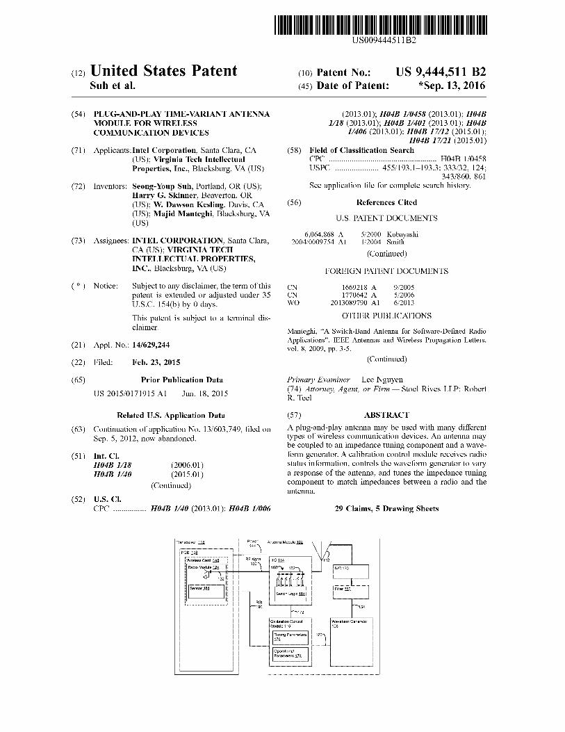
(57) ABSTRACTA plug-and-play antenna may be used with many differenttypes of wireless communication devices. An antenna maybe coupled to an impedance tuning component and a wave-
Int. CL form generator. A calibration control module receives radioHO4B 1/18 (2006.01) status information, controls the waveform generator to vary
HO4B 1/40 (2015.01) a response of the antenna, and tunes the impedance tuning(Continued) component to match impedances between a radio and the
antenna.
USS. Cl.
CPC oo H04B 1/40 (2013.01); HO4B 1/006 29 Claims, 5 Drawing Sheets
Transceiver 118 renee Antenna Module 102.
PCB 138 ‘\
(Wireless Card140| RF signal |[ito 114Radio Module 124 #30 ‘\ 160y 162,
ay, ttt ttOOD
Sensor 184. :Switch Logic 184}
RS! i
Teen 490 154
wre
Calibration Control
Module 416
Tuning Parameters ||170126 \
Waveform Generator
108
OperationalParameters 474

US 9,444,511 B2Page 2
(51) Int. Cl.HO4B 1/00HO4B 1/04
HO4B 1/401
HO04B 1/403
HO04B 17/12
HO4B 17/21
HO4B 1/26
(56)
(2006.01)(2006.01)(2015.01)(2015.01)(2015.01)(2015.01)(2006.01)
References Cited
U.S. PATENT DOCUMENTS
2005/0184922 Al2006/0094458 Al2007/0035356 Al2011/0166629 Al*
2011/0256841 Al*
8/20055/20062/20077/2011
10/2011
Ida etal.KitajiRantaDION weeccecceseeeeneees A6IN 1/08
607/60Kakuya wn... HO4B 1/18
455/334
2012/0088463 Al 4/2012 Rofougaran2014/0018020 Al* 1/2014 Suh we HO1Q 9/145
455/107
OTHER PUBLICATIONS
Manteghi, “Antenna Miniaturization Beyond the Fundamental Lim-
its Using Impedance Modulation”, IEEE Antennas and Propagation
Society International Symposium, 2009, 4 pages.Manteghi, “Non-LTI Systems, a New Frontier in ElectromagneticsTheory”, IEEE Antennas and Propagation Society InternationalSymposium (APSURSD),2010, 4 pages.PCT/US2013/046535, International Search Report and WrittenOpinion, Sep. 4, 2013, 15 pages.Peregrine Semiconductor Corp., “Peregrine Semiconductor UnveilsDigitally Tunable Capacitors Variable Capacitors Enable Fre-quency-agile Tunable Networks”, Jun. 8, 2011, 3 pages.
Peregrine Semiconductor Corp “Product Specification PE64904
Ultra CMOS® Digitally Tunable Capacitor (DTC) 100—3000
MHz”, 2011, pp. 1-11.
* cited by examiner

US 9,444,511 B2Sheet 1 of 5Sep. 13, 2016U.S. Patent
LeanGi4
SOE
JOPLIGUSS)WUOLOAGAA
pilSMBOWeIEd
jeucHeiedG
CobFOU
ootDAL
OZL
siepouieie,Buurye
OL,einpoy
jOHUOT)LIONeICHes)
Cbbeeen
POT
31607uoUMS
06)A
iSeal
Sy
sosues
nae
,Cel
th
peer
\(e
za.
Roos
\PEL
sinpoyyo1per,
Oct—
PitOU
uBisRy
ViPARA)
SBC1RJIAI
\Serdod
__
yl
__
ZOTainpoyw
euuayy|—
jemogSIT
seajsosuedy
US 9,444,511 B2Sheet 2 of 5Sep. 13, 2016
zein6i-
JO|ZISLISS)LUOLSABAA
Lon
PilSJePeWeEeYd
jeucieisdg
Sir
sugjouime.|Burn
STTeinpoyy
JOUODUOHeGIeD
OGL
iSa
shy
\OCL
AAPO,
O1bRed
jeuBis
4
ZLLAN
OF:
predSSajeAM—t
\Geb
dod
\pel
POEsinpoyBuUaTUy
LOMO
TT
seasosueiy
U.S. Patent

US 9,444,511 B2Sheet 3 of 5Sep. 13, 2016U.S. Patent
¢ani.
‘E6201807
YpImS
ml
[i
OsL—_—
acece
dee
meok
GitPLE
Siajsuleiedbe
sisjowiedBurn
jeuoneusedgG
ISG&_ogz
—\
an802
OTEsinpoyy
GLEPEE
SINpoyyJOYLISLIOT)
ULOLGARAAJOOS
UGHBICGHRDfojue75
uoneisdG
.O6E
ee
GLb
----QSa
!cscs
SG]31607
o6E
PS)
BIBO]USMS
Iosuesi
-PREsosuss
|
WTI
eBcedeob
aedeus
EL
i(
re
:+
“UrK091
\Och
(Pet
ainpowoipey
PLTOL
peuSisyy
|OPTpegSSIS|
\@Eb
@Od
PRLQOnSINpoyyeuuspuy
JaMGd
SLE
JSAIBISUBLE

U.S. Patent Sep. 13, 2016 Sheet 4 of 5 US 9,444,511 B2
—400
402NL Sensing EC nnn
404
{SEC ~ DEC] >>“ Threshold?
oN Adjusting impedance and/orantenna response
Figure 4
US 9,444,511 B2Sheet 5 of 5Sep. 13, 2016U.S. Patent
¢ainbi4
ces
396
PIBOIN
fam
JSAIGOSUBL|
BEG
BUUSIUYyae
seaiaspindinga~andy
0e5
SORLISIYIOMION
&a
O26
ye
e
SJOTOUIBIE
pegBOS
WOEoo;Bunend
2180)mmm
fsosset0ld
fOHUOSWBISAS
:
ors
@BelOlS/NANzw
965
ves
SISIOLUBIES
3160)Burne
els
AJORUGLLE
LUGISAS
NL
005

US 9,444,511 B2
1PLUG-AND-PLAY TIME-VARIANT ANTENNA
MODULE FOR WIRELESS
COMMUNICATION DEVICES
RELATED APPLICATION
This application claims priority benefit of U.S. patent
application Ser. No. 13/603,749, filed Sep. 5, 2012, which is
hereby incorporated by reference herein in its entirety.
TECHNICAL FIELD
Embodiments of the present disclosure generally relate to
the field of wireless communication devices, and more
particularly, to plug-and-play, time-variant antenna modules
for wireless communication devices.
BACKGROUND INFORMATION
Specified antenna performancecharacteristics are difficult
to maintain after antennas are installed in different mobile
devices. Even among mobile devices with identical or
similar form factors, slightly different antenna-installation
locations that may be attributable to manufacturing toler-
ances or errors typically result in deviations between the
specified and the actual antenna performance. These devia-
tions can negatively affect antenna performance and effi-
ciency. For example, an antenna installed at a location offset
by some distance (e.g., one or two millimeters) from itsspecified location may cause the antenna to deviate from its
specified resonate frequency, which may result in a poweramplifier wasting power while tuning the antenna to its
originally specified resonant frequency. This inefliciency
prematurely drains a battery of the mobile device, or resultsin suboptimal transmission and reception.
To address potential performance concerns, conventionalantennas are specifically designed for various form factors.
However, specifically designed antennas increase develop-ment costs and time-to-market for mobile devices. More-
over, once the antenna is installed, its efficiency cannot be
readily improved because the conventional antenna is spe-cifically designed andfully integrated with the transceiver in
the mobile device. Furthermore, even for specificallydesigned antennas, unpredictable manufacturing errors,
interference from the human body, or other environmentalconditions may degrade performance. For example, a user’s
hand or head touching the mobile device will typically
detune the antennato a degree that is often unpredictable, asit depends on a user’s physical characteristics, the way
mobile devices are held, or other environmental factors.Performance degradation of multi-band or broadband anten-
nas is difficult to dynamically improve because the environ-mental factors affecting the antenna may simultaneously
detune multiple (or broad) frequency bands employed by the
antenna.
BRIEF DESCRIPTION OF THE DRAWINGS
Aspects of embodiments will be apparent from the fol-lowing detailed description of embodiments, which pro-
ceeds with reference to the accompanying drawings.Embodimentsare illustrated by way of example and not by
wayof limitation in the figures of the accompanying draw-
ings.FIG.1 illustrates a plug-and-play antenna module and a
transceiver in accordance with some embodiments.
10
15
20
25
30
35
40
45
50
55
60
65
2FIG.2 illustrates a plug-and-play antenna module and a
transceiver in accordance with some embodiments.
FIG.3 illustrates a plug-and-play antenna module and a
transceiver in accordance with some embodiments.FIG.4 is a flowchart depicting a calibration operation in
accordance with some embodiments.FIG. 5 illustrates a system that may be used to practice
various embodiments described herein.
DESCRIPTION OF THE EMBODIMENTS
In the following detailed description, reference is made to
the accompanying drawingsthat form a part hereof, whereinlike numerals designate like parts throughout, and in which
is shown by wayofillustration, embodiments in which thesubject matter of the present disclosure may be practiced.
Various operations are described as multiple discrete
operations in turn, in a mannerthatis helpful in understand-ing the claimed subject matter. However, the order of
description should not be construed as to imply that theseoperations are necessarily order dependent. In particular,
these operations may not be performed in the order ofpresentation. Operations described may be performed in a
different order than the described embodiment. Various
additional operations may be performed and/or describedoperations may be omitted in additional embodiments.
For the purposes of the present disclosure, the phrase “Aand/or B” means(A), (B), or (A and B). For the purposes of
the present disclosure, the phrase “A, B, and/or C” means(A), (B), (C), (A and B), (A and C), (B and C), or (A, B and
C).The description may use the phrases “in an embodiment,”
or “in embodiments,” which may each refer to one or more
of the same or different embodiments. Furthermore, theterms “comprising,” “including,” “having,” and the like, as
used with respect to embodiments of the present disclosure,
are synonymous.As used herein, the term “module” may refer to, be part
of, or include an Application Specific Integrated Circuit(ASIC), an electronic circuit, a processor (shared, dedicated,
or group) and/or memory (shared, dedicated, or group) thatexecute one or more software or firmware programs, acombinational logic circuit, and/or other suitable compo-
nents that provide the described functionality.Original equipment manufacturers (OEMs) develop pro-
prietary industrial designs for mobile devices of variousform factors. To account for industrial design differences
that negatively affect antenna performance, conventionalantennas are specifically designed and integrated into par-
ticular mobile device models. However, it is challenging to
affordably and timely design for every different device aspecific, optimized antenna. Furthermore, manufacturing
errors and unpredictable environmental factors can degradethe antenna performance, even for fully integrated antenna
designs.According to embodiments described below, a dynami-
cally configurable plug-and-play antenna module is capable
ofchanging a resonance response ofthe antenna (hereinafter“antenna response”) for multiband, single band, and/or
broadband operational modes. Additionally, the plug-and-play antenna module maybecalibrated to match impedances
for various mobile device form factors, to adjust for vari-ances in antenna-installation locations attributable to manu-
facturing tolerances or errors, and to dynamically compen-
sate for various environmental factors. Thus, withoutchanging the antenna structure, the plug-and-play antenna
module may accommodate a variety of form factors having

US 9,444,511 B2
3a wide range of proprietary designs and manufacturingdifferences. Furthermore, once deployed and configured for
multi-band and broadband operation, the plug-and-play
antenna module dynamically enhances antenna performancein response to human body affects or other environmental
influences. Therefore, embodiments for a plug-and-playantenna module provide multiple operating modes andself-
calibration capability in wireless antenna systems for vari-ous mobile communication devices such as smartphones,
tablets, notebooks, netbooks, or other mobile devices.
FIG.1 illustrates a plug-and-play antenna module 102 inaccordance with some embodiments. The plug-and-play
antenna module 102 is a time-variant antenna moduleincluding a waveform generator 108, an antenna 112, an
impedance-tuning component (ITC) 114, and a calibrationcontrol module 116. In certain embodiments, the antenna
112 includes a passive antenna structure designed under
mobile device boundary conditions for one or more wirelesscommunication frequencies. The waveform generator 108,
ITC 114, and calibration control module 116 may be col-lectively implemented in silicon. As explained below, the
calibration control module 116 is configured to control theantenna response for multiband, single band, and/or broad-
band operational modes by producing with the waveform
generator 108 a voltage waveform (also referred to herein asa control waveform) that controls the capacitance of an
impedance-varying component (IVC) 120. In addition, thecalibration control module 116 is configured to improve
antenna efficiency by tuning the impedanceof the ITC 114to match the impedance ofthe antenna 112 with a transceiver
118 at operating frequencies.
The transceiver 118 includes a radio module 124. Theradio module 124 may be coupled with the ITC 114 by a
signaling interface 130 (e.g., a coaxial cable) for transmis-sion of a data-carrying signal, such as a radio-frequency
(RF) signal. The radio module 124 includes a transmission
line 132 to communicate (e.g., transmit/receive) the RFsignal with the antenna module 102 by wayofthe signaling
interface 130. In some embodiments, the radio module 124is disposed on a circuit board, such as printed circuit board
(PCB) 138. The radio module 124 may be directly coupledwith the PCB 138 or coupled with the PCB 138 through
another circuit board (e.g., wireless card 140). The antenna
module 102 receives power from a power interface 144,which may be disposed separately from the PCB 138 in
some embodiments.The waveform generator 108 is configured to generate
one ofa plurality of control waveformsthat it provides to afilter 152 via a control waveform interface 154. The filter
152 is coupled with the IVC 120 by an antenna signaling
interface, which may be a coaxial cable, to facilitate trans-mission ofthe control waveform to the IVC 120. The control
waveform is excited to the antenna 112 via the IVC 120,which may be a varactor, for example. Thefilter 152 passes
the control waveform to the IVC 120 by the antennasignaling interface while inhibiting the RF signal from
interfering with the waveform generator 108. Thus, the filter
152 provides at least some degree of isolation between thewaveform generator 108 and the transceiver 118.
The voltages of the control waveform vary (i.e., modulateand/or control) the capacitance of the IVC 120 and produce
controlled variations of the characteristic resonant frequen-cies of the antenna 112. A modulation frequency of the
control waveform may be greater than twice the radio signal
bandwidth to meet the Nyquist sampling theorem for trans-mitting/receiving data without data contamination. By vary-
ing the impedanceof the IVC 120, the antenna responseis
10
20
25
30
35
40
45
50
55
60
65
4configured (or dynamically reconfigured) to change a reso-nating frequency from a first band to a second band, from
one band to multi-bands, and/or from a relatively narrow-
band to a relatively wideband. For example, in someembodiments, a control waveform that is a square waveform
results in a dual-band antenna response, a control waveformthat is a tri-step waveform results in a tri-band antenna
response, and a control waveform that is a sawtooth wave-form results in a wideband antenna response. Thus, varying
amplitude, frequency, and/or shape of the control waveform
provides selectable antenna responses without any changesto the antenna structure. The capability of dynamically
reconfiguring the antenna response allows for the antenna112 to be smaller than a conventional antenna and/or allows
for the use of fewer antennas altogether. In some embodi-ments, the antenna 112 may be smaller than a conventional
antenna by thirty percent or more.
The ITC 114 includes a switchable impedance module160 that is dynamically tunable to match impedances
between the antenna module 102 and a corresponding trans-ceiver, such as the transceiver 118. The ITC 114 may be
designed to interface with the transceiver 118 at a standard-ized or predetermined impedance (e.g., fifty Ohms or
another impedance value), and the switchable impedance
module 160 is dynamically tunable to adjustfor variations inthe standardized or predetermined impedance value.
In addition to impedance matching capabilities, the swit-chable impedance module 160 mayalso provide impedance
at the antenna signaling interface that affects the antennaresponse and can therefore tune the antenna frequencies to
compensate for environmental changes attributable to
humanhandsor other environmental conditions, to differentinstallation locations for various different phone models
and/or manufacturing deviations, or to other conditions thatchange the impedanceof the transceiver 118.
As shown in FIG.1, in certain embodiments, the switch-
able impedance module 160 includes an array of capacitors162 (or other impedance tuning components) of different
values that are addressable with switch logic 164. Theswitch logic 164 is configured to electrically activate or
deactivate individual capacitors, and establish selected com-binations of active/inactive capacitors depending on a
desired impedance value. For example, the impedanceofthe
antenna module may be configurable by switching indi-vidual capacitors in the array of capacitors 162 between the
RF signaling interface 130 and ground. In some embodi-ments, and depending onthe desired resolution and range of
impendence values, five or six (for example) individualcapacitor elements are included in the array 162. For
example, a digitally tunable capacitor (DTC) that includes
switchable capacitors is model number PE64904 DuNE™DTC, available from Peregrine Semiconductor of San
Diego, Calif., USA. Persons skilled in the art will recognizefrom the disclosure herein, however, that other DTC may be
used, any number of capacitors may be used, and thatvarious different capacitor values may be used to achieve a
desired impedance tuning resolution.
The calibration control module 116 is coupled with theantenna module 102 and provides digital control signals to
the waveform generator 108 via an operational controlinterface 170, and provides digital control signals to the ITC
114 via a calibration control interface 172, which may be aserial data interface.
The calibration control module 116 provides an input to
the waveform generator 108 to configure the antenna 112 fora desired wireless transmission protocol. The calibration
control module 116 controls the waveform generator 108 in
US 9,444,511 B2
5a manner to apply control waveforms with appropriateamplitude, shape, and/or frequency to establish various
operational modes. In some embodiments, the calibration
control module 116 controls the waveform generator 108based on operational parameters 174. The operational
parameters 174, in some embodiments, are parameters thatrelate to an operational mode of the transceiver 118. For
example, in some embodiments, the transceiver 118switches from operating in a first operational mode in
accordance with a first protocol—e.g., digital television
(DTV), long-term evolution (LTE), WiFi, WiMAX, Blu-etooth, global positioning satellite (GPS), near field com-
munication (NFC), or another protocol—that uses a firstantenna response, to operating in a second operational mode
in accordance with a second protocol that uses a secondantenna response. Additionally, in some embodiments, dif-
ferent operational modes may also be used within one
protocol. For example, the transceiver 118 may usea firstantenna response for uplink communications and a second
antenna response for downlink communications. Otheroperational parameters may be additionally/alternatively
used in other embodiments.The calibration control module 116 also controls values
input to the ITC 114 by receiving impedance values for the
transceiver 118 and for the antenna 112, determinesa desiredcalibration control value, and provides the desired calibra-
tion control value to the ITC 114. In some embodiments, thecalibration control module 116 also concurrently controls
the waveform generator 108 based on the tuning parameters176.
The tuning parameters 176, in some embodiments, are
parameters that relate to the operating environment of thetransceiver 118, or its components. For example, in some
embodiments, the position of a user’s hand holding a mobilecommunication device hosting the transceiver 118 detunes
the antenna response. In another example, an antenna
response deviates from an expected antenna response to aless optimal antenna response uponinstallation and place-
mentof the antenna module 102 in a mobile communicationdevice. In either example, the calibration control module 116
controls the ITC 114 to tune the antenna response to com-pensate for environmental changes. In such a manner, the
antenna response may be adapted to a particular environ-
ment in which the antenna 112 is operating.In various embodiments, the calibration control module
116 may be pre-programmedwith the tuning parameters 176(e.g., at assembly of the mobile communication device)
and/or may receive the tuning parameters 176 dynamicallythrough operation. In one embodiment, the radio module
124 may include a sensor 184 to sense changesin electrical
characteristics associated with the transmission line 132and/or RF signal on the signaling interface 130. For
example, the sensor 184 detects signal power of the RFsignal, output impedance of the radio module 124, or other
electrical characteristics. These sensed changes mayindicatethat an antenna response has become detuned. The sensor
184 may generate radio status information (RSI) based on
these sensedelectrical characteristics and feed the RSI backto the calibration control module 116 via an RSI interface
190. The calibration control module 116 then adjusts theantenna response based on the RSI. In other embodiments,
a similar sensor may be located in or coupled to the antennamodule 102 and/or outside the radio module 124 in the
transceiver 118.
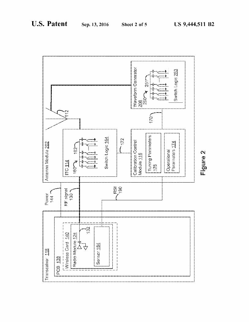
FIG.2 illustrates a plug-and-play antenna module 202 inaccordance with some embodiments. The antenna module
202 includes a waveform generator 208, an antenna 112, an
10
15
20
25
30
35
40
45
50
55
60
65
6ITC 114, and a calibration control module 116 that aresimilar to previously described components, except as noted
below. Additionally, a transceiver 118 shown in FIG. 2 and
its components operate similar to the transceiver 118 shownin FIG. 1 and its components, except as otherwise noted.
In this embodiment, rather than producing a voltagewaveform, the waveform generator 208 includes a switch-
able impedance module 250 that is similar to the switchableimpedance module 160. The switchable impedance module
250 includes an array of capacitors 251 and switch logic
253, which the waveform generator 208 uses to produce aplurality of different digitally controlled “capacitance wave-
forms” to modulate the impedance at an antenna signalinginterface and control the antenna response, as described
above. For example, the switchable impedance module 250may switch back and forth between two capacitance values
to generate a square capacitance waveform applied to an
input of the antenna 112 that produces a dual-band antennaresponse. As other examples, the switchable impedance
module 250 generates a tri-step capacitance waveform thatproduces a tri-band antenna response, and the switchable
impedance module 250 generates a sawtooth capacitancewaveform that produces a wideband antenna response.
Skilled persons will recognize from the disclosure herein
that other capacitance waveforms may be used to generateother antenna responses. Thus, varying amplitude, fre-
quency, and/or shape of the capacitance waveform providesselectable antenna responses without any changes to the
antenna structure. The capacitance values of the switchableimpedance module 250 are selected to produce the capaci-
tance waveforms with desired resolutions. In other embodi-
ments, an ITC and waveform generator are combined anduse a single switchable impedance module that functions in
a similar manneras a standalone ITC, waveform generator,and/or IVC.
FIG. 3 illustrates a plug-and-play antenna module 302
according to another embodiment. The antenna module 302includes a waveform generator 208, an antenna 112, and an
ITC 114 that are similar to previously described compo-nents. However, in this embodiment, a calibration control
component 316 communicates to a transceiver 318 via acalibration control interface 319. The transceiver 318
includes an operational control module 334 that has opera-
tional parameters 374 similar to operational parameters 174.Thetransceiver 318 receives RS] from sensor 384 via an RSI
interface 390 that is internal to the transceiver 318, andestablishes an operational mode based on the operational
parameters 374. Operational mode information is conveyedto the calibration control module 316 by way ofthe control
interface 319. The calibration control module 316 uses
operational mode information alone, or in combination withother electrical characteristics received from, for example,
an antenna sensor 394 via an antenna sensorinterface 396,to control the waveform generator 208 and the ITC 114, as
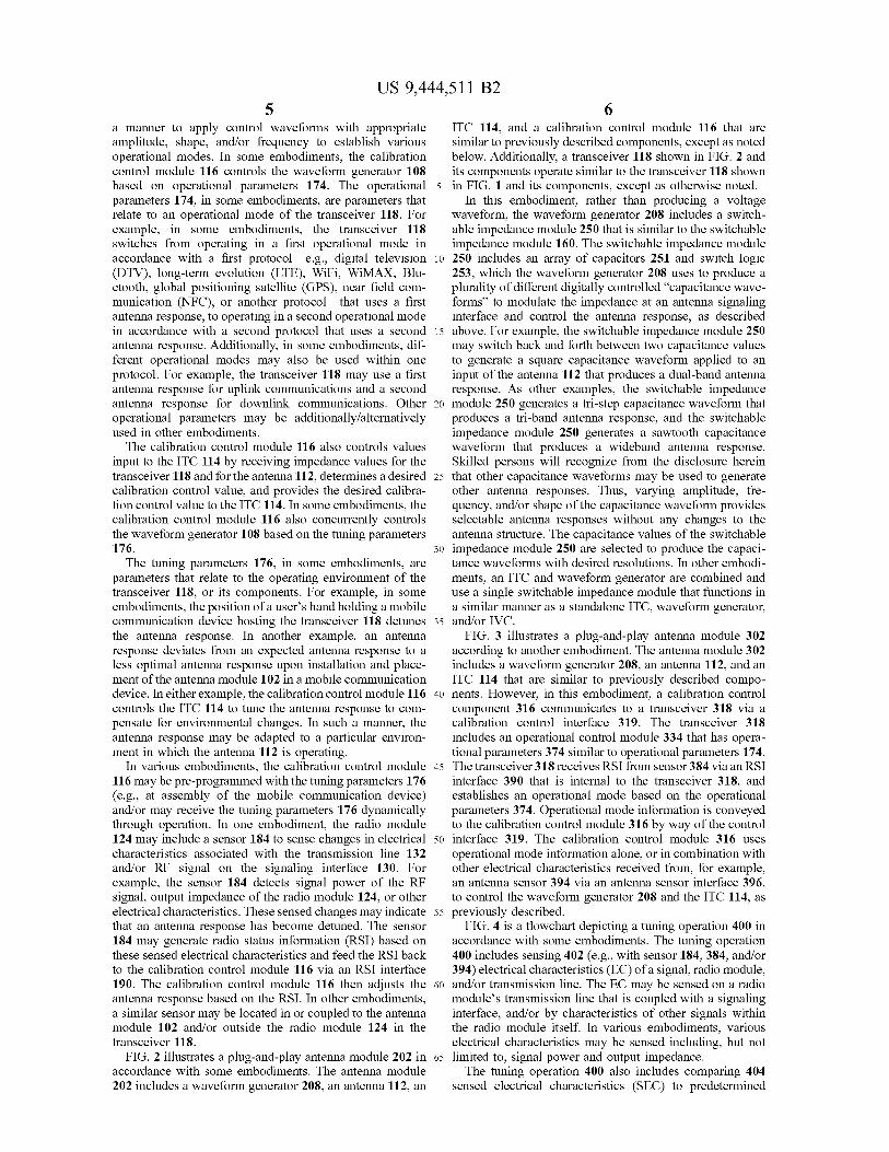
previously described.FIG.4 is a flowchart depicting a tuning operation 400 in
accordance with some embodiments. The tuning operation
400 includes sensing 402 (e.g., with sensor 184, 384, and/or394) electrical characteristics (EC) of a signal, radio module,
and/or transmission line. The EC may be sensed on a radiomodule’s transmission line that is coupled with a signaling
interface, and/or by characteristics of other signals withinthe radio module itself. In various embodiments, various
electrical characteristics may be sensed including, but not
limited to, signal power and output impedance.The tuning operation 400 also includes comparing 404
sensed electrical characteristics (SEC) to predetermined

US 9,444,511 B2
7desired electrical characteristics (DEC). The DEC may be arange of permissible or expected values of the particular
electrical characteristics. The comparing 404 may include
determining whether an absolute value of a differencebetween the SEC and the DEC is greater than a predeter-
mined threshold value. The predetermined threshold valuemay correspond with the range of permissible or expected
values.If it is determinedthat the difference between the SEC and
the DECis greater than the predetermined threshold value,
the tuning operation 400 includes adjusting 406 an imped-ance of a plug-and-play antenna module (e.g., antenna
modules 102, 202, and 302) and/or adjusting a controlwaveform. The adjusting may occur by a calibration control
module (e.g., calibration control module 116 or 316) pro-viding appropriate digital control signals to an impedance
tuning component (e.g., ITC 114) and to a waveform gen-
erator (e.g., waveform generator 108 or 208). The tuningoperation 400 may then loop back to sensing 402 of the EC.
If, however, it is determined 404 that the differencebetween the SEC and the DEC is less than or equal to the
predetermined threshold value, the tuning operation 400may loop back to sensing 402 of the EC.
Calibration of the antenna module, according to certain
embodiments, can be performed dynamically andat varioustimes depending on actual or anticipated factors that affect
the antenna response. For example, three calibration routinesare contemplated as follows, presented in order of increasing
calibration precision: a primary, secondary, and final cali-bration.
The primary calibration is a relatively coarse calibration
performed prior to installation (or following shortly there-after) ofthe antenna module. The primary calibration routine
accounts for different transceiver impedance specifications,for mobile-device boundary conditions attributable to form
factor differences, or for other proprietary industrial design
differences.The secondary calibration routine is employed upon
completion of the OEM-assembly stage to automaticallyaccount for manufacturing errors or deviations among simi-
lar or identical mobile communication devices.Once the mobile communication device is shipped to a
user, the final calibration routine is employed to sense
conditions such as the presence of a humanhand, or otherenvironmental changes, and then dynamically adjust the
impedance with ITC based on the transceiver impedance,and optionally tune the antenna response depending on how
the user is holding the phone, for example.The plug-and-play antenna modules described herein may
be implemented into a system using any suitable hardware
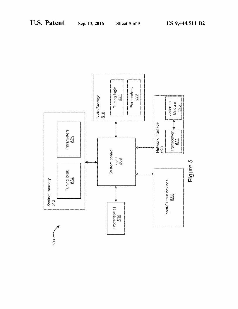
and/or software to configure as desired. FIG.5 illustrates, forone embodiment, an example system 500, such as a mobile
phone or other mobile communication device, comprisingone or more processor(s) 504, system control logic 508
coupled with at least one of the processor(s) 504, systemmemory 512 coupled with the system control logic 508,
non-volatile memory (NVM)/storage 516 coupled with the
system control logic 508, and a network interface 520coupled with the system control logic 508.
The processor(s) 504 may include one or more single-coreor multi-core processors. The processor(s) 504 may include
any combination of general-purpose processors and dedi-cated processors (e.g., graphics processors, application pro-
cessors, or other processors).
System control logic 508 for one embodiment mayinclude any suitable interface controllers to provide for any
suitable interface to at least one of the processor(s) 504
10
15
20
25
30
35
40
45
50
55
60
65
8and/or to any suitable device or component in communica-tion with the system control logic 508.
The system control logic 508 for one embodiment may
include one or more memory controller(s) to provide aninterface to the system memory 512. The system memory
512 may beused to load and store data and/orinstructions,for example, for the system 500. The system memory 512
for one embodiment may include any suitable volatilememory, such as suitable dynamic random access memory
(DRAM), for example.
The NVM/storage 516 may include one or moretangible,non-transitory computer-readable media used to store data
and/or instructions, for example. The NVM/storage 516 mayinclude any suitable non-volatile memory, such as flash
memory, for example, and/or may include any suitablenon-volatile storage device(s), such as one or more hard disk
drive(s) (HDD(s)), one or more compact disk (CD)drive(s),
and/or one or more digital versatile disk (DVD) drive(s) forexample.
The NVM/storage 516 may include a storage resourcephysically part of a device on which the system 500 is
installed or it may be accessible by, but not necessarily a partof, the device. For example, the NVM/storage 516 may be
accessed over a network via the network interface 520.
The system memory 512 and the NVM/storage 516 mayrespectively include, in particular, temporal and persistent
copies of tuning logic 524 and parameters 526, e.g., opera-tional and tuning parameters. The tuning logic 524 may
include instructions that, when executed by at least one ofthe processor(s) 504, result in the system 500 performing
tuning operations described herein. In some embodiments,
the tuning logic 524, or hardware, firmware, and/or softwarecomponents thereof, may additionally/alternatively be
located in the system control logic 508, the network inter-face 520, and/or the processor(s) 504.
The network interface 520 may have a transceiver 522
coupled to a plug-and-play antenna module 523 to providea radio interface for the system 500 to communicate over
one or more network(s) and/or with any other suitabledevice. The network interface 520 may include any suitable
hardware and/or firmware. The network interface 520 mayinclude a plurality of antenna modules to provide a MIMO
radio interface. The network interface 520, for one embodi-
ment, may include a network adapter, a wireless networkadapter, a telephone modem,and/or a wireless modem.
The transceiver 522 may be similar to, and substantiallyinterchangeable with, transceivers 118 and/or 318. Likewise,
the antenna module 523 may be similar to, and substantiallyinterchangeable with, antenna modules 102, 202, and/or
302. In various embodiments, the transceiver 522 or antenna
module 523 may be integrated with other components of thesystem 500. For example, the transceiver 522 may include a
processor of the processor(s) 504, memory of the systemmemory 512, and NVM/Storage of the NVM/Storage 516.
For one embodiment, at least one of the processor(s) 504may be packaged together with logic for one or more
controller(s) of the system control logic 508. For one
embodiment, at least one of the processor(s) 504 may bepackaged together with logic for one or more controllers of
the system control logic 508 to form a System in Package(SiP). For one embodiment, at least one of the processor(s)
504 may be integrated on the same die with logic for one ormore controller(s) of the system control logic 508. For one
embodiment, at least one of the processor(s) 504 may be
integrated on the same die with logic for one or morecontroller(s) of the system control logic 508 to form a
System on Chip (SoC).

US 9,444,511 B2
9The system 500 may further include input/output (1/O)
devices 532. The I/O devices 532 may include user inter-
faces designed to enable user interaction with the system
500, peripheral component interfaces designed to enableperipheral componentinteraction with the system 500, and/
or sensors designed to determine environmental conditionsand/or location information related to the system 500.
In various embodiments, the user interfaces could include,but are notlimited to, a display (e.g., a liquid crystal display,
a touch screen display, etc.), a speaker, a microphone, one or
more cameras(e.g., a still camera and/or a video camera), aflashlight (e.g., a light emitting diode flash), and a keyboard.
In various embodiments, the peripheral component inter-faces may include, but are not limited to, a non-volatile
memory port, an audio jack, and a power supply interface.In various embodiments, the sensors may include, but are
not limited to, a gyro sensor, an accelerometer, a proximity
sensor, an ambient light sensor, and a positioning unit. Thepositioning unit may also be part of, or interact with, the
network interface 520 to communicate with components ofa positioning network, e.g., a global positioning system
(GPS)satellite.In various embodiments, the system 500 may be a mobile
computing device such as, but not limited to, a laptop
computing device, a tablet computing device, a netbook, asmartphone, etc. In various embodiments, the system 500
may have more or less components, and/or different archi-tectures.
Tt will be understood by skilled persons that manychanges may be madeto the details of the above-described
embodiments without departing from the underlying prin-
ciples of the invention. The scope of the present inventionshould, therefore, be determined only by the following
claims.The invention claimedis:
1. An antenna module configured to communicate a radio
frequency (RF) signal with a transceiver, the antenna mod-ule comprising:
an antenna;
an impedance tuning component coupled to the antenna,
the impedance tuning component to match an imped-ance of the antenna to the transceiverat a plurality of
operating frequencies;
a waveform generator coupled to the antenna, the wave-form generator to generate a control waveform; and
a calibration control module coupled with the transceiverand the waveform generator, the calibration control
module to control the waveform generator to selec-tively provide the control waveform to vary a response
of the antenna, and to selectively tune the impedance
tuning component.2. The antenna module of claim 1, wherein the waveform
generator is configured to generate a voltage waveform.3. The antenna module of claim 2, further comprising:
an impedance varying component coupled between thewaveform generator and the antenna, the impedance
varying componentresponsiveto the voltage waveform
to produce controlled variations of characteristic reso-nant frequencies of the antenna.
4. The antenna module of claim 3, further comprising:a filter coupled in line with the impedance varying com-
ponent between the waveform generator and theantenna.
5. The antenna module of claim 3, wherein the impedance
varying component comprises a varactor.6. The antenna module of claim 1, wherein the waveform
generator is configured to generate a capacitance waveform.
25
35
40
45
50
65
107. The antenna module of claim 6, wherein the waveform
generator comprises a switchable impedance module.
8. The antenna module of claim 1, wherein the waveform
generator, the calibration control module, and the impedance
tuning component are monolithically integrated in a com-
mon die.
9. The antenna module of claim 1, wherein the impedance
tuning component comprises a switchable impedance mod-
ule.
10. The antenna module of claim 1, further comprising:
a sensor coupled with an RF transmission line and con-
figured to provide antenna and/orradio status informa-
tion to the calibration control module based on an RF
signal on the RF transmission line.
11. The antenna module of claim 1, wherein the calibra-
tion control module is configured to control the waveform
generator based on pre-programmed tuning parameters.
12. The antenna module of claim 1, wherein the calibra-
tion control module is configured to control the waveform
generator based on operational parameters.
13. The antenna module of claim 1, wherein the antenna
comprises a passive antenna structure designed under
mobile device boundary conditions for one or more wireless
communication frequencies.
14. A method for controlling a time-variant antenna
module, comprising:
generating a control waveform to vary a response of an
antenna and thereby provide a selected operating fre-
quency of the time-variant antenna module;
sensing an electrical characteristic associated with the
antenna and/or a radio;
comparing the sensed electrical characteristic to prede-
termined desired electrical characteristics; and
adjusting, based on said comparing, a switchable imped-
ance value to match impedances between the antenna
and the radio at the selected operating frequency of the
time-variant antenna module.
15. The method of claim 14, wherein said comparing
includes:
determining that an absolute value of a difference between
the sensed electrical characteristics and the desired
electrical characteristics is greater than a predeterminedvalue.
16. The method of claim 14, wherein the electrical char-acteristic is an input impedance ofan antenna module and/or
output impedance of a radio module.17. The method of claim 14, wherein the predetermined
desired electrical characteristics are associated with a mobile
device form factor.18. The method of claim 14, wherein the predetermined
desired electrical characteristics are associated with manu-facturing tolerances of a particular mobile device form
factor.19. The method of claim 14, wherein the sensedelectrical
characteristics correspond to environmental effects.
20. An antenna module, comprising:an antenna for transmitting and receiving radio frequency
(RF) signals;meansfor tuning an impedanceofthe antennain response
to changing environmental conditions; andmeans for varying a response of the antenna to change
between operational modes.
21. The antenna module of claim 20, wherein the opera-tional modes are selected from a group comprising multi-
band, single band, and broadband operational modes.

US 9,444,511 B2
1122. A mobile communication device, comprising:
a radio module; and
an antenna module coupled with the radio module by a
signaling interface configured to convey a radio-fre-
quency (RF) signal between the radio and antenna
modules, the antenna module including:
an antenna;
an impedance tuning component coupled to the antenna
and to the signaling interface;
a waveform generator; anda calibration control module coupled with the waveform
generator and with the impedance tuning component,the calibration control module configured to receive
radio status information and, based on the radio statusinformation, to control the waveform generator to vary
a response of the antenna, and to tune the impedance
tuning component to match impedances between theradio and antenna modules.
23. The mobile communication device of claim 22, fur-ther comprising:
an impedance varying component responsive to the volt-
age waveform, wherein the waveform generator isconfigured to generate a voltage waveform.
24. The mobile communication device of claim 22,wherein the waveform generator is configured to generate a
5
10
15
20
12capacitance waveform, and wherein the waveform generatorcomprises a switchable impedance module.
25. The mobile communication device of claim 22,
wherein the radio module comprises:a transmission line to communicate the RF signal with the
signaling interface; anda sensor proximal the signaling interface, the sensor
configured to sense an electrical characteristic associ-ated with the RF signal or the transmission line and to
generate the radio status information based on the
sensed electrical characteristic.26. The mobile communication device of claim 25,
wherein the sensed electrical characteristic corresponds toan input impedance of the antenna module and/or an output
impedance of the radio during operation of the mobilecommunication device.
27. The mobile communication device of claim 22,
wherein the signaling interface comprises a coaxial cable.28. The mobile communication device of claim 22,
wherein the calibration control module and the impedancetuning component are coupled via a serial interface.
29. The mobile communication device of claim 22,wherein the impedance tuning component includes a swit-
chable impedance module.
* * * * *