aa-07-01 evolver 202 solventborne robotic atomizers (draft)
TRANSCRIPT
EVOLEVOLEVOLEVOLEVOLVER 202VER 202VER 202VER 202VER 202TMTMTMTMTM SOL SOL SOL SOL SOLVENTBORNEVENTBORNEVENTBORNEVENTBORNEVENTBORNE
ROBOTIC AROBOTIC AROBOTIC AROBOTIC AROBOTIC ATTTTTOMIZERSOMIZERSOMIZERSOMIZERSOMIZERS
SERVICE MANUAL
AA-07-01AA-07-01AA-07-01AA-07-01AA-07-01June - 2007
MODEL: A1MODEL: A1MODEL: A1MODEL: A1MODEL: A11918-XXX1918-XXX1918-XXX1918-XXX1918-XXX
IMPORIMPORIMPORIMPORIMPORTTTTTANTANTANTANTANT: Before using this equipment, care-: Before using this equipment, care-: Before using this equipment, care-: Before using this equipment, care-: Before using this equipment, care-
fully read SAFETY PRECAUTIONS, starting onfully read SAFETY PRECAUTIONS, starting onfully read SAFETY PRECAUTIONS, starting onfully read SAFETY PRECAUTIONS, starting onfully read SAFETY PRECAUTIONS, starting on
page 1, and all instructions in this manual. Keeppage 1, and all instructions in this manual. Keeppage 1, and all instructions in this manual. Keeppage 1, and all instructions in this manual. Keeppage 1, and all instructions in this manual. Keep
this Service Manual for future reference.this Service Manual for future reference.this Service Manual for future reference.this Service Manual for future reference.this Service Manual for future reference.
Service Manual Price: Service Manual Price: Service Manual Price: Service Manual Price: Service Manual Price: €40.00 (Euro)40.00 (Euro)40.00 (Euro)40.00 (Euro)40.00 (Euro)
$50.00 (U.S.)$50.00 (U.S.)$50.00 (U.S.)$50.00 (U.S.)$50.00 (U.S.)
WithWithWithWithWith
TTTTTechnologyechnologyechnologyechnologyechnology

AA-07-01
DDDDDRAFTRAFTRAFTRAFTRAFT
AA-07-01
SAFETY:SAFETY:SAFETY:SAFETY:SAFETY:
SAFETY PRECAUTIONS.............................................................................................................
HAZARDS / SAFEGUARDS.........................................................................................................
PAGEPAGEPAGEPAGEPAGE
INTRODUCTION:INTRODUCTION:INTRODUCTION:INTRODUCTION:INTRODUCTION:
CONTENTSCONTENTSCONTENTSCONTENTSCONTENTS
ITW RANSBURG ELECTROSTATIC PROCESS......................................................................
EVOLVER 202 SOLVENTBORNE SPRAY APPLICATORS....................................................
SPECIFICATIONS.......................................................................................................................
EVOLVER 202 APPLICATOR ASSEMBLY................................................................................
EVOLVER 202 TUBING BUNDLE ASSEMBLY (ENGLISH).....................................................
EVOLVER 202 TUBING BUNDLE ASSEMBLY (METRIC).......................................................
EVOLVER 202 SOLVENTBORNE ROBOTIC ATOMIZER APPLICATORS............................
FEATURES..................................................................................................................................
A11918-XXX EVOLVER SPRAY APPLICATOR ASSEMBLY..................................................
TOOL CENTER-POINT COMPARISONS TABLE.....................................................................
1-41-41-41-41-4
5-145-145-145-145-14
1
2-4
5
5-6
7
8
9
10
11
12
13
14
Evolver 202 Robotic Atomizers - Contents
INSTALLATION:INSTALLATION:INSTALLATION:INSTALLATION:INSTALLATION:
EVOLVER 202 ROBOTIC ATOMIZER INSTALLATION............................................................
POWER SUPPLY ASSEMBLY...................................................................................................
LOW VOLTAGE CABLE CONNECTIONS.................................................................................
EVOLVER SPRAY APPLICATOR AIR AND FLUID LAYOUT..................................................
APPLICATOR AND MANIFOLD ASSEMBLY............................................................................
LOW VOLTAGE CABLE INSTALLATIONS................................................................................
SIGNAL IDENTIFICATION TABLES (ENGLISH/METRIC).......................................................
APPLICATOR AND MANIFOLD ASSEMBLY / PARTS LIST....................................................
SPRAY / BELL APPLICATOR TRIGGERING............................................................................
CONVERSION SCHEMATIC......................................................................................................
15-2215-2215-2215-2215-22
15
15
16
17
18
18-19
20
21
22
22
OPERATION:OPERATION:OPERATION:OPERATION:OPERATION:
SPRAY APPLICATOR CONTROLS...........................................................................................
HVLP SPRAY...............................................................................................................................
FLUID VALVE CONTROLS.........................................................................................................
DUAL PURGE SPRAYING.........................................................................................................
23-2623-2623-2623-2623-26
23
23
23
24-26
MAINTENANCE:MAINTENANCE:MAINTENANCE:MAINTENANCE:MAINTENANCE:
ROUTINE MAINTENANCE SCHEDULE.....................................................................................
PROCEDURES.............................................................................................................................
SPRAY HEAD REMOVAL / ASSEMBLY / PARTS LIST..........................................................
SERVICE......................................................................................................................................
SPRAY HEAD ASSEMBLY..........................................................................................................
79138 EVOLVER APPLICATOR HEAD ASSEMBLY / PARTS LIST........................................
27-5227-5227-5227-5227-52
27-28
28-29
31-32
33
33-35
37-38
(Continued On Next Page)(Continued On Next Page)(Continued On Next Page)(Continued On Next Page)(Continued On Next Page)
AA-07-01
Evolver 202 Robotic Atomizers- Contents
PARTS IDENTIFICATION:PARTS IDENTIFICATION:PARTS IDENTIFICATION:PARTS IDENTIFICATION:PARTS IDENTIFICATION:
A11918 SPRAY APPLICATOR ASSEMBLY / PARTS LIST......................................................
79138-01 SPRAY HEAD ASSEMBLY / PARTS LIST.................................................................
79179-00 SINGLE HEAD 60° / PARTS LIST...............................................................................
79243-00 DUAL HEAD 60° / PARTS LIST...................................................................................
79180-00 SINGLE HEAD 90° / PARTS LIST...............................................................................
79224-00 DUAL HEAD 90° / PARTS LIST...................................................................................
A11917 MANIFOLD ASSEMBLY / PARTS LIST.........................................................................
79105-01 REAR PLATE ASSEMBLY (UN-REGULATED VERSION) /
PARTS LIST..................................................................................................................................
A10747-00 REAR PLATE ASSEMBLY (REGULATOR VERSION) /
PARTS LIST..................................................................................................................................
REAR PLATE / BREAK-AWAY ASSEMBLY (SINGLE PAINT
WITH REGULATOR MANIFOLD ASSEMBLY ONLY) / PARTS LIST.......................................
79106-XXXXXXX TUBING BUNDLE ASSEMBLY (ENGLISH) / PARTS LIST..........................
A10892-XXXXXXX TUBING BUNDLE ASSEMBLY (METRIC) / PARTS LIST.........................
A10406 OR LECU5004 MICROPAK CONTROL UNIT...............................................................
ACCESSORIES AND SERVICE KITS........................................................................................
REPAIR KITS................................................................................................................................
SERVICE PARTS.........................................................................................................................
LUBRICANTS AND SEALERS....................................................................................................
RECOMMENDED SPARE PARTS.............................................................................................
53-8853-8853-8853-8853-88
53-54
55-57
58
58
59
59
61-63
64
65
66
67-72
73-78
79
79-81
82-83
84
84
85-87
WARRANTY POLICIES:WARRANTY POLICIES:WARRANTY POLICIES:WARRANTY POLICIES:WARRANTY POLICIES: 8989898989
LIMITED WARRANTY.................................................................................................................. 89
MAINTENANCE (Cont.):MAINTENANCE (Cont.):MAINTENANCE (Cont.):MAINTENANCE (Cont.):MAINTENANCE (Cont.): 27-5227-5227-5227-5227-52
REMOVING SPRAY APPLICATOR FROM THE
REAR MANIFOLD ASSEMBLY...................................................................................................
EVOLVER 202 60° SINGLE HEAD APPLICATOR
ASSEMBLY / PARTS LIST...........................................................................................................
MOUNTING BLOCK, SHROUD HALVES AND RETAINING
RING REMOVAL / PARTS LIST..................................................................................................
DISASSEMBLY OF INTERMEDIATE APPLICATOR
HOUSING / PARTS LIST.............................................................................................................
LOW VOLTAGE CABLE REMOVAL / PARTS LIST...................................................................
79103-00 DUAL PURGE VALVE MANIFOLD
DISASSEMBLY / PARTS LIST.....................................................................................................
79103-01 SINGLE PURGE VALVE MANIFOLD
DISASSEMBLY / PARTS LIST.....................................................................................................
REGULATOR VALVE MANIFOLD ASSEMBLY.........................................................................
A10745 FLUID REGULATOR ASSEMBLY / PARTS LIST.........................................................
TROUBLESHOOTING GUIDE....................................................................................................
39
40
41
43-44
45-46
47
47
48
49
50-52
PAGEPAGEPAGEPAGEPAGE

AA-07-01
Evolver 202 Robotic Atomizers - Contents
AA-07-01
SAFETY PRECAUTIONSSAFETY PRECAUTIONSSAFETY PRECAUTIONSSAFETY PRECAUTIONSSAFETY PRECAUTIONS
Before operating, maintaining or servicing anyITW Ransburg electrostatic coating system, readand understand all of the technical and safetyliterature for your ITW Ransburg products. Thismanual contains information that is important foryou to know and understand. This informationrelates to USER SAFETY and PREVENTINGEQUIPMENT PROBLEMS. To help you recog-nize this information, we use the following sym-bols. Please pay particular attention to thesesections.
A WARNING!A WARNING!A WARNING!A WARNING!A WARNING! states information to alert you to astates information to alert you to astates information to alert you to astates information to alert you to astates information to alert you to asituation that might cause serious injury if in-situation that might cause serious injury if in-situation that might cause serious injury if in-situation that might cause serious injury if in-situation that might cause serious injury if in-structions are not followed.structions are not followed.structions are not followed.structions are not followed.structions are not followed.
A CAUTION! states information that tells how toA CAUTION! states information that tells how toA CAUTION! states information that tells how toA CAUTION! states information that tells how toA CAUTION! states information that tells how toprevent damage to equipment or how to avoid aprevent damage to equipment or how to avoid aprevent damage to equipment or how to avoid aprevent damage to equipment or how to avoid aprevent damage to equipment or how to avoid asituation that might cause minor injury.situation that might cause minor injury.situation that might cause minor injury.situation that might cause minor injury.situation that might cause minor injury.
A NOTE is information relevant to the procedureA NOTE is information relevant to the procedureA NOTE is information relevant to the procedureA NOTE is information relevant to the procedureA NOTE is information relevant to the procedurein progress.in progress.in progress.in progress.in progress.
While this manual lists standard specificationsand service procedures, some minor deviationsmay be found between this literature and yourequipment. Differences in local codes and plantrequirements, material delivery requirements, etc.,make such variations inevitable. Compare thismanual with your system installation drawings andappropriate Ransburg equipment manuals to rec-oncile such differences.
Careful study and continued use of this manual willprovide a better understanding of the equipmentand process, resulting in more efficient operation,longer trouble-free service and faster, easiertroubleshooting. If you do not have the manualsand safety literature for your ITW Ransburg sys-tem, contact your local ITW Ransburg representa-tive or ITW Ransburg.
SAFETYSAFETYSAFETYSAFETYSAFETY
> The hazards shown on the following page
may occur during the normal use of thisequipment. Please read the hazard chartbeginning on page 2.
W A R N I N GW A R N I N GW A R N I N GW A R N I N GW A R N I N G!!!!!
> The user MUSTMUSTMUSTMUSTMUST read and be familiar with
the Safety Section in this manual and theITW Ransburg safety literature therein iden-tified.
> This manual MUSTMUSTMUSTMUSTMUST be read and thor-
oughly understood by ALLALLALLALLALL personnel whooperate, clean or maintain this equipment!Special care should be taken to ensure thatthe WARNINGSWARNINGSWARNINGSWARNINGSWARNINGS and safety requirementsfor operating and servicing the equipmentare followed. The user should be aware ofand adhere to ALLALLALLALLALL local building and firecodes and ordinances as well as NFPA-33NFPA-33NFPA-33NFPA-33NFPA-33
SAFETY STANDARD or applicableSAFETY STANDARD or applicableSAFETY STANDARD or applicableSAFETY STANDARD or applicableSAFETY STANDARD or applicable
country safety standards country safety standards country safety standards country safety standards country safety standards prior to install-ing, operating, and/or servicing this equip-ment.
W A R N I N GW A R N I N GW A R N I N GW A R N I N GW A R N I N G!!!!!
11111
Evolver 202 Robotic Atomizers - Safety
AA-07-01
AREAAREAAREAAREAAREA
Tells where hazards
may occur.
HAZARDHAZARDHAZARDHAZARDHAZARD
Tells what the hazard is.
SAFEGUARDSSAFEGUARDSSAFEGUARDSSAFEGUARDSSAFEGUARDS
Tells how to avoid the hazard.
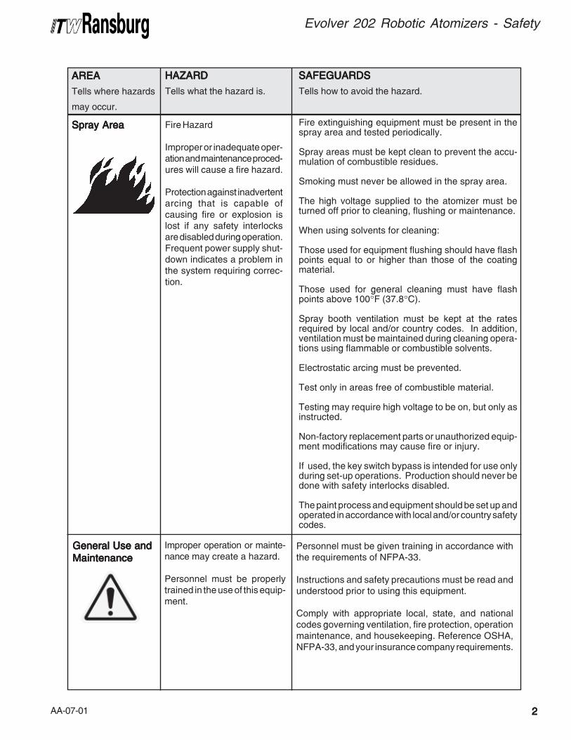
Spray AreaSpray AreaSpray AreaSpray AreaSpray Area
Improper operation or mainte-nance may create a hazard.
Personnel must be properlytrained in the use of this equip-ment.
Personnel must be given training in accordance withthe requirements of NFPA-33.
Instructions and safety precautions must be read andunderstood prior to using this equipment.
Comply with appropriate local, state, and nationalcodes governing ventilation, fire protection, operationmaintenance, and housekeeping. Reference OSHA,NFPA-33, and your insurance company requirements.
General Use andGeneral Use andGeneral Use andGeneral Use andGeneral Use and
MaintenanceMaintenanceMaintenanceMaintenanceMaintenance
Fire Hazard
Improper or inadequate oper-ation and maintenance proced-ures will cause a fire hazard.
Protection against inadvertentarcing that is capable ofcausing fire or explosion islost if any safety interlocksare disabled during operation.Frequent power supply shut-down indicates a problem inthe system requiring correc-tion.
Fire extinguishing equipment must be present in thespray area and tested periodically.
Spray areas must be kept clean to prevent the accu-mulation of combustible residues.
Smoking must never be allowed in the spray area.
The high voltage supplied to the atomizer must beturned off prior to cleaning, flushing or maintenance.
When using solvents for cleaning:
Those used for equipment flushing should have flashpoints equal to or higher than those of the coatingmaterial.
Those used for general cleaning must have flashpoints above 100°F (37.8°C).
Spray booth ventilation must be kept at the ratesrequired by local and/or country codes. In addition,ventilation must be maintained during cleaning opera-tions using flammable or combustible solvents.
Electrostatic arcing must be prevented.
Test only in areas free of combustible material.
Testing may require high voltage to be on, but only asinstructed.
Non-factory replacement parts or unauthorized equip-ment modifications may cause fire or injury.
If used, the key switch bypass is intended for use onlyduring set-up operations. Production should never bedone with safety interlocks disabled.
The paint process and equipment should be set up andoperated in accordance with local and/or country safetycodes.
22222
Evolver 202 Robotic Atomizers - Safety
AA-07-0133333
Evolver 202 Robotic Atomizers - Safety
AREAAREAAREAAREAAREA
Tells where hazards
may occur.
HAZARDHAZARDHAZARDHAZARDHAZARD
Tells what the hazard is.
SAFEGUARDSSAFEGUARDSSAFEGUARDSSAFEGUARDSSAFEGUARDS
Tells how to avoid the hazard.
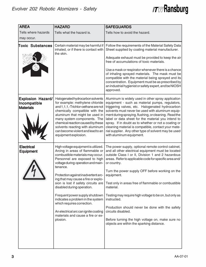
ElectricalElectricalElectricalElectricalElectrical
EquipmentEquipmentEquipmentEquipmentEquipment
High voltage equipment is utilized.Arcing in areas of flammable orcombustible materials may occur.Personnel are exposed to highvoltage during operation and main-tenance.
Protection against inadvertent arc-ing that may cause a fire or explo-sion is lost if safety circuits aredisabled during operation.
Frequent power supply shutdownindicates a problem in the systemwhich requires correction.
An electrical arc can ignite coatingmaterials and cause a fire or ex-plosion.
The power supply, optional remote control cabinet,and all other electrical equipment must be locatedoutside Class I or II, Division 1 and 2 hazardousareas. Refer to applicable code for specific area and/or country.
Turn the power supply OFF before working on theequipment.
Test only in areas free of flammable or combustiblematerial.
Testing may require high voltage to be on, but only asinstructed.
Production should never be done with the safetycircuits disabled.
Before turning the high voltage on, make sure noobjects are within the sparking distance.
Explosion Hazard/Explosion Hazard/Explosion Hazard/Explosion Hazard/Explosion Hazard/
IncompatibleIncompatibleIncompatibleIncompatibleIncompatible
MaterialsMaterialsMaterialsMaterialsMaterials
Halogenated hydrocarbon solventsfor example: methylene chlorideand 1,1,1,-Trichlor-oethane are notchemically compatible with thealuminum that might be used inmany system components. Thechemical reaction caused by thesesolvents reacting with aluminumcan become violent and lead to anequipment explosion.
Aluminum is widely used in other spray applicationequipment - such as material pumps, regulators,triggering valves, etc. Halogenated hydrocarbonsolvents must never be used with aluminum equip-ment during spraying, flushing, or cleaning. Read thelabel or data sheet for the material you intend tospray. If in doubt as to whether or not a coating orcleaning material is compatible, contact your mate-rial supplier. Any other type of solvent may be usedwith aluminum equipment.
Toxic SubstancesToxic SubstancesToxic SubstancesToxic SubstancesToxic Substances Certain material may be harmful ifinhaled, or if there is contact withthe skin.
Follow the requirements of the Material Safety DataSheet supplied by coating material manufacturer.
Adequate exhaust must be provided to keep the airfree of accumulations of toxic materials.
Use a mask or respirator whenever there is a chanceof inhaling sprayed materials. The mask must becompatible with the material being sprayed and itsconcentration. Equipment must be as prescribed byan industrial hygienist or safety expert, and be NIOSHapproved.
AA-07-01 44444
Evolver 202 Robotic Atomizers - Safety
AREAAREAAREAAREAAREA
Tells where hazards
may occur.
HAZARDHAZARDHAZARDHAZARDHAZARD
Tells what the hazard is.
SAFEGUARDSSAFEGUARDSSAFEGUARDSSAFEGUARDSSAFEGUARDS
Tells how to avoid the hazard.
Personnel SafetyPersonnel SafetyPersonnel SafetyPersonnel SafetyPersonnel Safety Skin puncturing by sharp electrode. Take precautions to see that flesh is not puncturedby sharp electrode.
Robot Work AreaRobot Work AreaRobot Work AreaRobot Work AreaRobot Work Area
-General Use and-General Use and-General Use and-General Use and-General Use and
MaintenanceMaintenanceMaintenanceMaintenanceMaintenance
Improper use or maintenance canlead to hazardous conditions, par-ticularly from unexpected robotmanipulator movement.
Applicator adjustments or maintenance should bedone after the robot is taken out of service. Do notadjust or repair the applicator if the robot is operatingor standing ready to start.
Refer to robot operating instructions for the proce-dures to take the robot out of service.
AA-07-01
THE ITW RANSBURGTHE ITW RANSBURGTHE ITW RANSBURGTHE ITW RANSBURGTHE ITW RANSBURG
ELECTROSTELECTROSTELECTROSTELECTROSTELECTROSTAAAAATICTICTICTICTIC
PROCESSPROCESSPROCESSPROCESSPROCESS
This process is a method for electrostaticallyapplying coatings to objects. A power supplyproduces a high voltage charge which is suppliedto the applicator, creating an electrostatic fieldbetween the applicator and the target object. Thetarget is electrostatically grounded through itssupport which may be either stationary or moving.
A regulated fluid system delivers coating materialto the applicator, where it is atomized forming aspray mist. There, under the influence of theelectrostatic field, the atomized coating becomeselectrostatically charged. The charged particlesare attracted to and deposited on the groundedtarget object. The forces between the chargedparticles and the target are sufficient to turnoverspray around and deposit it on the back surfaceof the target. Therefore, a higher percentage ofthe spray is deposited.
INTRODUCTIONINTRODUCTIONINTRODUCTIONINTRODUCTIONINTRODUCTION
55555
Evolver 202 Robotic Atomizers - Introduction
EVOLEVOLEVOLEVOLEVOLVER 202™VER 202™VER 202™VER 202™VER 202™
SOLSOLSOLSOLSOLVENTBORNE SPRAVENTBORNE SPRAVENTBORNE SPRAVENTBORNE SPRAVENTBORNE SPRAYYYYY
APPLICAAPPLICAAPPLICAAPPLICAAPPLICATTTTTORSORSORSORSORS
The Evolver 202 Spray Applicators SystemEvolver 202 Spray Applicators SystemEvolver 202 Spray Applicators SystemEvolver 202 Spray Applicators SystemEvolver 202 Spray Applicators Systemwill allow for the use of spray applicators or bellapplicators with minimal required down-time duringthe switching process. This system can alsooperate as a spray applicator system only thatlater can be upgraded to allow for bell applicatorsto be used. Lastly, this system can allow a usercurrently possessing an RMA-202 bell system touse spray applicators as well, with minimal conver-sion required. The Evolver 202 solventborneapplicator line consists of both 60° and 90° singleand dual-headed 100 kV automatic electrostaticapplicators. Developed for use on robots, theEvolver 202 spray applicator incorporates a unique1/3 turn quick-disconnect spray head and a twopiece bolt together manifold cover, providing theuser an efficient tool for the electrostatic applicationof coatings.
The Evolver 202 spray applicator also has theability to color change while spraying with novoltage draw down, a true dual purge function(depending on the unit purchased).
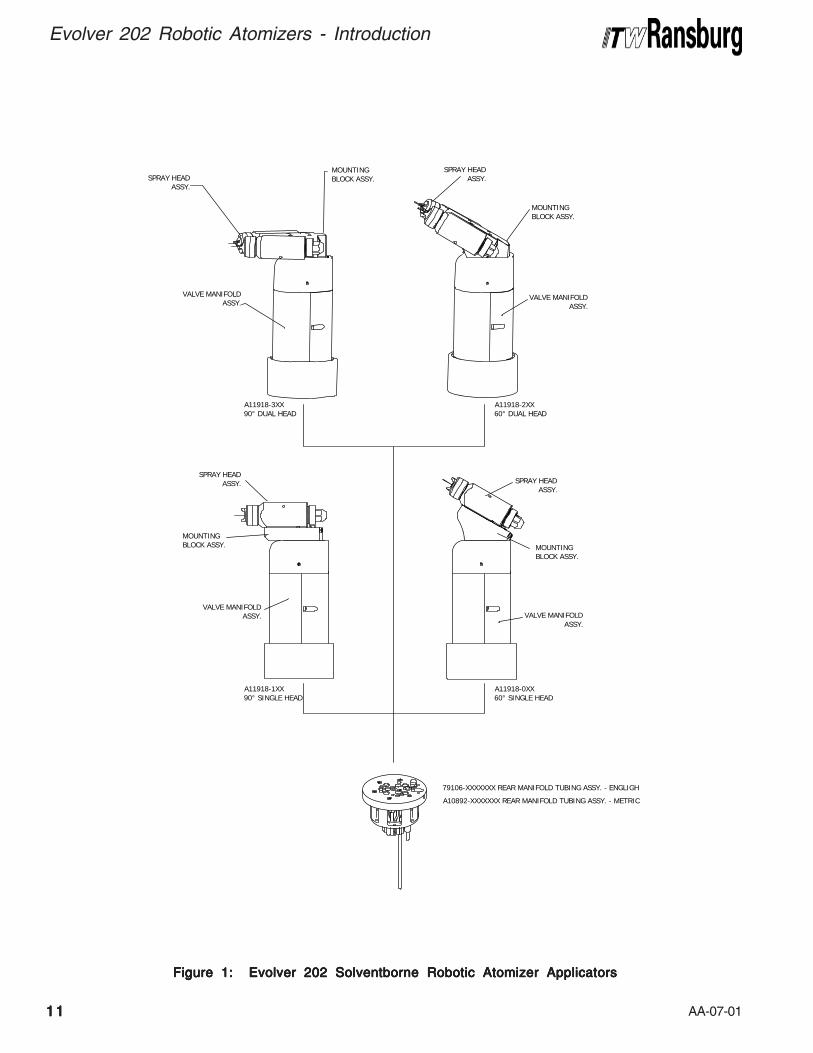
There are two single head models of the Evolver202 applicator (see Figure 1). Each model differsin the applicator to axis orientation of the sprayhead. These models are:
A11918-0XX 60° Single HeadA11918-1XX 90° Single Head
Two dual-head versions of the Evolver 202 appli-cator are also available (see Figure 1). The dualheaded applicators are primarily used where highvolume fluid delivery is required. The dual headedapplicator is available in two different configura-tions as follows:
A11918-2XX 60° Dual HeadA11918-3XX 90° Dual Head
AA-07-01
Evolver 202 Robotic Atomizers - Introduction
66666
The Evolver 202 spray applicator system con-sists of four major components:
1. Quick-Disconnect Spray Head2. Gun Head Mounting Block Assembly3. Valve Manifold Assembly (Includes the High
Voltage Cascade with a Quick-DisconnectRing)
4. Rear Tubing Manifold Assembly (both Englishand Metric)
The spray head(s) and valve manifold contain thefluid, air, and high voltage passages. All fluidpassages contain stainless steel and/or nylonfittings, compatible with halogenated hydrocarbonsolvents. The robot manifold incorporates stain-less steel fluid connections.
The high voltage cascade is entirely encapsulatedwith a solvent resistant epoxy. This cascadegenerates voltages up to 100 kV fed by a lowvoltage cable.
There are three sources for the high voltagesupply to the Evolver 202 applicators:
• MicroPak™ Control Unit (LECU5004)(for non-FM installations)
• Stand-alone control/power supply unit (A10406) (for FM installations)
• MicroPakTM Control Unit (LECU5004-31)(for FM installations)
The MicroPak Power Supply Control unit providesa low voltage signal through the robot manifold tothe spray applicator. The high voltage cascadelocated within the applicator converts the lowvoltage DC signal to a high voltage electrostaticoutput.
NOTESNOTESNOTESNOTESNOTES
AA-07-01
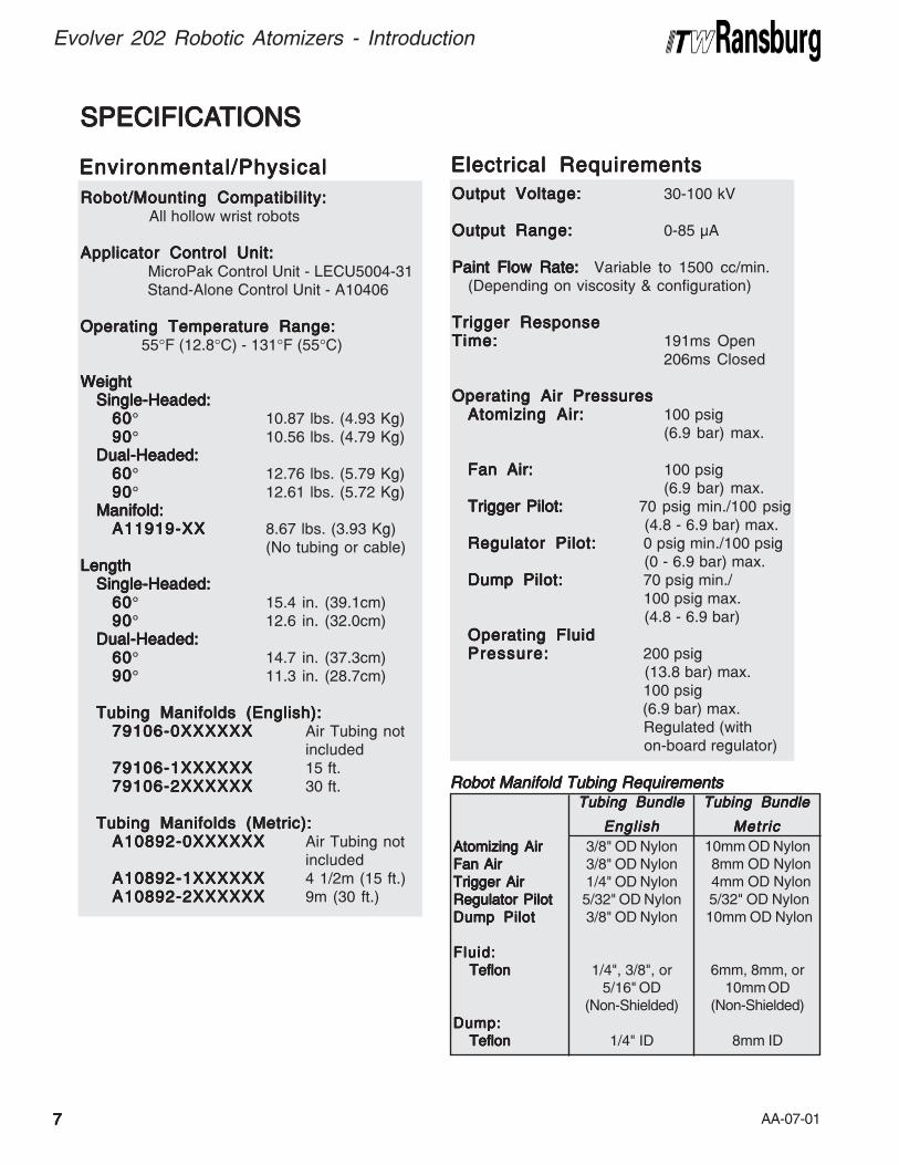
Output Voltage:Output Voltage:Output Voltage:Output Voltage:Output Voltage: 30-100 kV
Output Range:Output Range:Output Range:Output Range:Output Range: 0-85 μA
Paint Flow Rate: Paint Flow Rate: Paint Flow Rate: Paint Flow Rate: Paint Flow Rate: Variable to 1500 cc/min.(Depending on viscosity & configuration)
Trigger ResponseTrigger ResponseTrigger ResponseTrigger ResponseTrigger ResponseTime:Time:Time:Time:Time: 191ms Open
206ms Closed
Operating Air PressuresOperating Air PressuresOperating Air PressuresOperating Air PressuresOperating Air PressuresAtomizing Air:Atomizing Air:Atomizing Air:Atomizing Air:Atomizing Air: 100 psig
(6.9 bar) max.
Fan Air:Fan Air:Fan Air:Fan Air:Fan Air: 100 psig(6.9 bar) max.
Trigger Pilot: Trigger Pilot: Trigger Pilot: Trigger Pilot: Trigger Pilot: 70 psig min./100 psig (4.8 - 6.9 bar) max.
Regulator Pilot:Regulator Pilot:Regulator Pilot:Regulator Pilot:Regulator Pilot: 0 psig min./100 psig (0 - 6.9 bar) max.
Dump Pilot:Dump Pilot:Dump Pilot:Dump Pilot:Dump Pilot: 70 psig min./ 100 psig max. (4.8 - 6.9 bar)
Operating FluidOperating FluidOperating FluidOperating FluidOperating FluidPressure:Pressure:Pressure:Pressure:Pressure: 200 psig
(13.8 bar) max. 100 psig
(6.9 bar) max. Regulated (with
on-board regulator)
Robot/Mounting Compatibility:Robot/Mounting Compatibility:Robot/Mounting Compatibility:Robot/Mounting Compatibility:Robot/Mounting Compatibility: All hollow wrist robots
Applicator Control Unit:Applicator Control Unit:Applicator Control Unit:Applicator Control Unit:Applicator Control Unit: MicroPak Control Unit - LECU5004-31 Stand-Alone Control Unit - A10406
Operating Temperature Range:Operating Temperature Range:Operating Temperature Range:Operating Temperature Range:Operating Temperature Range: 55°F (12.8°C) - 131°F (55°C)
WeightWeightWeightWeightWeightSingle-Headed:Single-Headed:Single-Headed:Single-Headed:Single-Headed:
6060606060° 10.87 lbs. (4.93 Kg)9090909090° 10.56 lbs. (4.79 Kg)
Dual-Headed:Dual-Headed:Dual-Headed:Dual-Headed:Dual-Headed:6060606060° 12.76 lbs. (5.79 Kg)9090909090° 12.61 lbs. (5.72 Kg)
Manifold:Manifold:Manifold:Manifold:Manifold:A11919-XXA11919-XXA11919-XXA11919-XXA11919-XX 8.67 lbs. (3.93 Kg)
(No tubing or cable)LengthLengthLengthLengthLength
Single-Headed:Single-Headed:Single-Headed:Single-Headed:Single-Headed:6060606060° 15.4 in. (39.1cm)9090909090° 12.6 in. (32.0cm)
Dual-Headed:Dual-Headed:Dual-Headed:Dual-Headed:Dual-Headed:6060606060° 14.7 in. (37.3cm)9090909090° 11.3 in. (28.7cm)
Tubing Manifolds (English):Tubing Manifolds (English):Tubing Manifolds (English):Tubing Manifolds (English):Tubing Manifolds (English):79106-0XXXXXX79106-0XXXXXX79106-0XXXXXX79106-0XXXXXX79106-0XXXXXX Air Tubing not
included79106-1XXXXXX79106-1XXXXXX79106-1XXXXXX79106-1XXXXXX79106-1XXXXXX 15 ft.79106-2XXXXXX79106-2XXXXXX79106-2XXXXXX79106-2XXXXXX79106-2XXXXXX 30 ft.
Tubing Manifolds (Metric):Tubing Manifolds (Metric):Tubing Manifolds (Metric):Tubing Manifolds (Metric):Tubing Manifolds (Metric):A10892-0XXXXXXA10892-0XXXXXXA10892-0XXXXXXA10892-0XXXXXXA10892-0XXXXXX Air Tubing not
includedA10892-1XXXXXXA10892-1XXXXXXA10892-1XXXXXXA10892-1XXXXXXA10892-1XXXXXX 4 1/2m (15 ft.)A10892-2XXXXXXA10892-2XXXXXXA10892-2XXXXXXA10892-2XXXXXXA10892-2XXXXXX 9m (30 ft.)
SPECIFICASPECIFICASPECIFICASPECIFICASPECIFICATIONSTIONSTIONSTIONSTIONS
Atomizing AirAtomizing AirAtomizing AirAtomizing AirAtomizing Air
Fan AirFan AirFan AirFan AirFan Air
Trigger AirTrigger AirTrigger AirTrigger AirTrigger Air
Regulator PilotRegulator PilotRegulator PilotRegulator PilotRegulator Pilot
Dump PilotDump PilotDump PilotDump PilotDump Pilot
Fluid:Fluid:Fluid:Fluid:Fluid:
Teflon Teflon Teflon Teflon Teflon
Dump:Dump:Dump:Dump:Dump:
Teflon Teflon Teflon Teflon Teflon
RRRRRobot Manifold Tubing Requirementsobot Manifold Tubing Requirementsobot Manifold Tubing Requirementsobot Manifold Tubing Requirementsobot Manifold Tubing RequirementsTubing BundleTubing BundleTubing BundleTubing BundleTubing Bundle
EnglishEnglishEnglishEnglishEnglish
Tubing BundleTubing BundleTubing BundleTubing BundleTubing Bundle
MetricMetricMetricMetricMetric
3/8" OD Nylon3/8" OD Nylon1/4" OD Nylon5/32" OD Nylon3/8" OD Nylon
1/4", 3/8", or5/16" OD
(Non-Shielded)
1/4" ID
10mm OD Nylon 8mm OD Nylon 4mm OD Nylon 5/32" OD Nylon 10mm OD Nylon
6mm, 8mm, or10mm OD
(Non-Shielded)
8mm ID
Environmental/PhysicalEnvironmental/PhysicalEnvironmental/PhysicalEnvironmental/PhysicalEnvironmental/Physical Electrical RequirementsElectrical RequirementsElectrical RequirementsElectrical RequirementsElectrical Requirements
77777
Evolver 202 Robotic Atomizers - Introduction
AA-07-01
Evolver 202 Robotic Atomizers - Introduction
88888
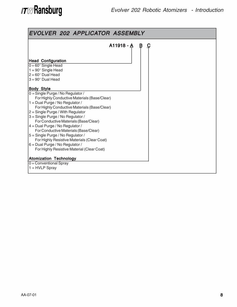
EVOLEVOLEVOLEVOLEVOLVER 202 APPLICAVER 202 APPLICAVER 202 APPLICAVER 202 APPLICAVER 202 APPLICATTTTTOR ASSEMBLOR ASSEMBLOR ASSEMBLOR ASSEMBLOR ASSEMBLYYYYY
Head ConfigurationHead ConfigurationHead ConfigurationHead ConfigurationHead Configuration0 = 60° Single Head1 = 90° Single Head2 = 60° Dual Head3 = 90° Dual Head
Body StyleBody StyleBody StyleBody StyleBody Style0 = Single Purge / No Regulator /
For Highly Conductive Materials (Base/Clear)1 = Dual Purge / No Regulator /
For Highly Conductive Materials (Base/Clear)2 = Single Purge / With Regulator3 = Single Purge / No Regulator /
For Conductive Materials (Base/Clear)4 = Dual Purge / No Regulator /
For Conductive Materials (Base/Clear)5 = Single Purge / No Regulator /
For Highly Resistive Materials (Clear Coat)6 = Dual Purge / No Regulator /
For Highly Resistive Material (Clear Coat)
Atomization TechnologyAtomization TechnologyAtomization TechnologyAtomization TechnologyAtomization Technology0 = Conventional Spray1 = HVLP Spray
A11918 - A B C A11918 - A B C A11918 - A B C A11918 - A B C A11918 - A B C
AA-07-0199999
Evolver 202 Robotic Atomizers - Introduction
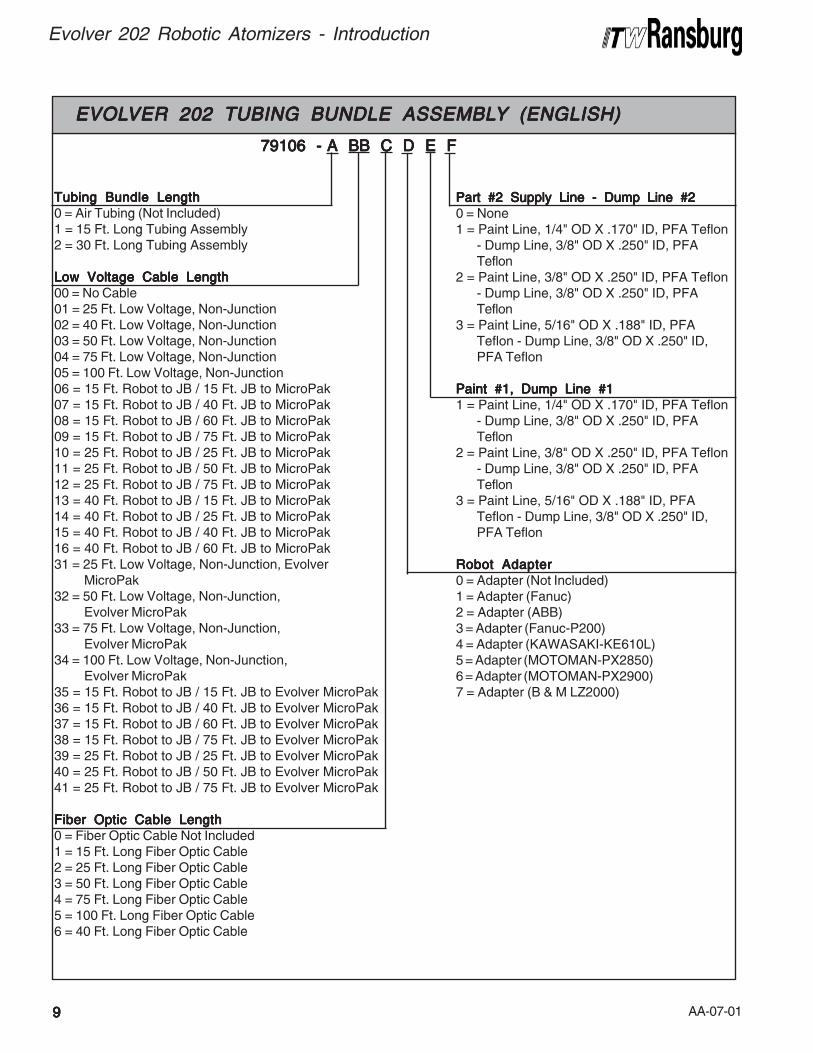
EVOLEVOLEVOLEVOLEVOLVER 202 TUBING BUNDLE ASSEMBLVER 202 TUBING BUNDLE ASSEMBLVER 202 TUBING BUNDLE ASSEMBLVER 202 TUBING BUNDLE ASSEMBLVER 202 TUBING BUNDLE ASSEMBLYYYYY (ENGLISH) (ENGLISH) (ENGLISH) (ENGLISH) (ENGLISH)
Tubing Bundle LengthTubing Bundle LengthTubing Bundle LengthTubing Bundle LengthTubing Bundle Length0 = Air Tubing (Not Included)1 = 15 Ft. Long Tubing Assembly2 = 30 Ft. Long Tubing Assembly
Low Voltage Cable LengthLow Voltage Cable LengthLow Voltage Cable LengthLow Voltage Cable LengthLow Voltage Cable Length00 = No Cable01 = 25 Ft. Low Voltage, Non-Junction02 = 40 Ft. Low Voltage, Non-Junction03 = 50 Ft. Low Voltage, Non-Junction04 = 75 Ft. Low Voltage, Non-Junction05 = 100 Ft. Low Voltage, Non-Junction06 = 15 Ft. Robot to JB / 15 Ft. JB to MicroPak07 = 15 Ft. Robot to JB / 40 Ft. JB to MicroPak08 = 15 Ft. Robot to JB / 60 Ft. JB to MicroPak09 = 15 Ft. Robot to JB / 75 Ft. JB to MicroPak10 = 25 Ft. Robot to JB / 25 Ft. JB to MicroPak11 = 25 Ft. Robot to JB / 50 Ft. JB to MicroPak12 = 25 Ft. Robot to JB / 75 Ft. JB to MicroPak13 = 40 Ft. Robot to JB / 15 Ft. JB to MicroPak14 = 40 Ft. Robot to JB / 25 Ft. JB to MicroPak15 = 40 Ft. Robot to JB / 40 Ft. JB to MicroPak16 = 40 Ft. Robot to JB / 60 Ft. JB to MicroPak31 = 25 Ft. Low Voltage, Non-Junction, Evolver
MicroPak32 = 50 Ft. Low Voltage, Non-Junction,
Evolver MicroPak33 = 75 Ft. Low Voltage, Non-Junction,
Evolver MicroPak34 = 100 Ft. Low Voltage, Non-Junction,
Evolver MicroPak35 = 15 Ft. Robot to JB / 15 Ft. JB to Evolver MicroPak36 = 15 Ft. Robot to JB / 40 Ft. JB to Evolver MicroPak37 = 15 Ft. Robot to JB / 60 Ft. JB to Evolver MicroPak38 = 15 Ft. Robot to JB / 75 Ft. JB to Evolver MicroPak39 = 25 Ft. Robot to JB / 25 Ft. JB to Evolver MicroPak40 = 25 Ft. Robot to JB / 50 Ft. JB to Evolver MicroPak41 = 25 Ft. Robot to JB / 75 Ft. JB to Evolver MicroPak
Fiber Optic Cable LengthFiber Optic Cable LengthFiber Optic Cable LengthFiber Optic Cable LengthFiber Optic Cable Length0 = Fiber Optic Cable Not Included1 = 15 Ft. Long Fiber Optic Cable2 = 25 Ft. Long Fiber Optic Cable3 = 50 Ft. Long Fiber Optic Cable4 = 75 Ft. Long Fiber Optic Cable5 = 100 Ft. Long Fiber Optic Cable6 = 40 Ft. Long Fiber Optic Cable
79106 - A BB C D E F 79106 - A BB C D E F 79106 - A BB C D E F 79106 - A BB C D E F 79106 - A BB C D E F
Part #2 Supply Line - Dump Line #2Part #2 Supply Line - Dump Line #2Part #2 Supply Line - Dump Line #2Part #2 Supply Line - Dump Line #2Part #2 Supply Line - Dump Line #20 = None1 = Paint Line, 1/4" OD X .170" ID, PFA Teflon
- Dump Line, 3/8" OD X .250" ID, PFATeflon
2 = Paint Line, 3/8" OD X .250" ID, PFA Teflon- Dump Line, 3/8" OD X .250" ID, PFATeflon
3 = Paint Line, 5/16" OD X .188" ID, PFATeflon - Dump Line, 3/8" OD X .250" ID,PFA Teflon
Paint #1, Dump Line #1Paint #1, Dump Line #1Paint #1, Dump Line #1Paint #1, Dump Line #1Paint #1, Dump Line #11 = Paint Line, 1/4" OD X .170" ID, PFA Teflon
- Dump Line, 3/8" OD X .250" ID, PFATeflon
2 = Paint Line, 3/8" OD X .250" ID, PFA Teflon- Dump Line, 3/8" OD X .250" ID, PFATeflon
3 = Paint Line, 5/16" OD X .188" ID, PFATeflon - Dump Line, 3/8" OD X .250" ID,PFA Teflon
Robot AdapterRobot AdapterRobot AdapterRobot AdapterRobot Adapter0 = Adapter (Not Included)1 = Adapter (Fanuc)2 = Adapter (ABB)3 = Adapter (Fanuc-P200)4 = Adapter (KAWASAKI-KE610L)5 = Adapter (MOTOMAN-PX2850)6 = Adapter (MOTOMAN-PX2900)7 = Adapter (B & M LZ2000)
AA-07-01
Evolver 202 Robotic Atomizers - Introduction
1010101010
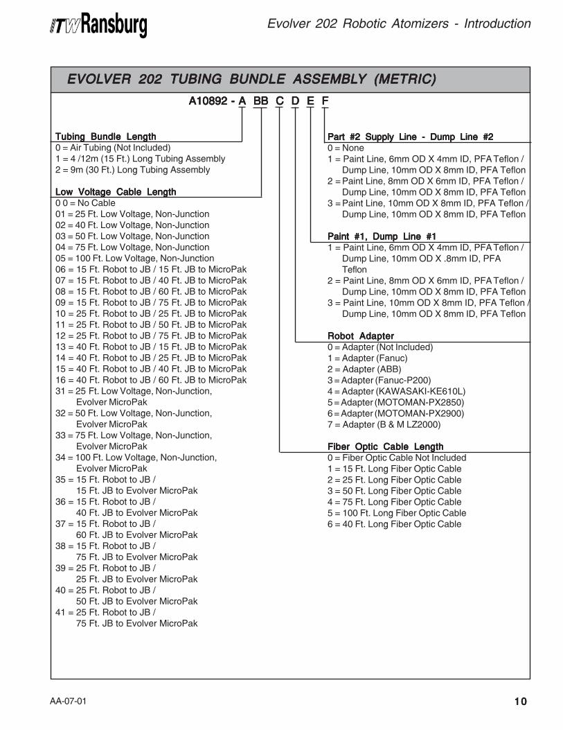
NOTESNOTESNOTESNOTESNOTESEVOLEVOLEVOLEVOLEVOLVER 202 TUBING BUNDLE ASSEMBLVER 202 TUBING BUNDLE ASSEMBLVER 202 TUBING BUNDLE ASSEMBLVER 202 TUBING BUNDLE ASSEMBLVER 202 TUBING BUNDLE ASSEMBLYYYYY (METRIC) (METRIC) (METRIC) (METRIC) (METRIC)
Tubing Bundle LengthTubing Bundle LengthTubing Bundle LengthTubing Bundle LengthTubing Bundle Length0 = Air Tubing (Not Included)1 = 4 /12m (15 Ft.) Long Tubing Assembly2 = 9m (30 Ft.) Long Tubing Assembly
Low Voltage Cable LengthLow Voltage Cable LengthLow Voltage Cable LengthLow Voltage Cable LengthLow Voltage Cable Length0 0 = No Cable01 = 25 Ft. Low Voltage, Non-Junction02 = 40 Ft. Low Voltage, Non-Junction03 = 50 Ft. Low Voltage, Non-Junction04 = 75 Ft. Low Voltage, Non-Junction05 = 100 Ft. Low Voltage, Non-Junction06 = 15 Ft. Robot to JB / 15 Ft. JB to MicroPak07 = 15 Ft. Robot to JB / 40 Ft. JB to MicroPak08 = 15 Ft. Robot to JB / 60 Ft. JB to MicroPak09 = 15 Ft. Robot to JB / 75 Ft. JB to MicroPak10 = 25 Ft. Robot to JB / 25 Ft. JB to MicroPak11 = 25 Ft. Robot to JB / 50 Ft. JB to MicroPak12 = 25 Ft. Robot to JB / 75 Ft. JB to MicroPak13 = 40 Ft. Robot to JB / 15 Ft. JB to MicroPak14 = 40 Ft. Robot to JB / 25 Ft. JB to MicroPak15 = 40 Ft. Robot to JB / 40 Ft. JB to MicroPak16 = 40 Ft. Robot to JB / 60 Ft. JB to MicroPak31 = 25 Ft. Low Voltage, Non-Junction,
Evolver MicroPak32 = 50 Ft. Low Voltage, Non-Junction,
Evolver MicroPak33 = 75 Ft. Low Voltage, Non-Junction,
Evolver MicroPak34 = 100 Ft. Low Voltage, Non-Junction,
Evolver MicroPak35 = 15 Ft. Robot to JB /
15 Ft. JB to Evolver MicroPak36 = 15 Ft. Robot to JB /
40 Ft. JB to Evolver MicroPak37 = 15 Ft. Robot to JB /
60 Ft. JB to Evolver MicroPak38 = 15 Ft. Robot to JB /
75 Ft. JB to Evolver MicroPak39 = 25 Ft. Robot to JB /
25 Ft. JB to Evolver MicroPak40 = 25 Ft. Robot to JB /
50 Ft. JB to Evolver MicroPak41 = 25 Ft. Robot to JB /
75 Ft. JB to Evolver MicroPak
A10892 - A BB C D E F A10892 - A BB C D E F A10892 - A BB C D E F A10892 - A BB C D E F A10892 - A BB C D E F
Part #2 Supply Line - Dump Line #2Part #2 Supply Line - Dump Line #2Part #2 Supply Line - Dump Line #2Part #2 Supply Line - Dump Line #2Part #2 Supply Line - Dump Line #20 = None1 = Paint Line, 6mm OD X 4mm ID, PFA Teflon /
Dump Line, 10mm OD X 8mm ID, PFA Teflon2 = Paint Line, 8mm OD X 6mm ID, PFA Teflon /
Dump Line, 10mm OD X 8mm ID, PFA Teflon3 = Paint Line, 10mm OD X 8mm ID, PFA Teflon /
Dump Line, 10mm OD X 8mm ID, PFA Teflon
Paint #1, Dump Line #1Paint #1, Dump Line #1Paint #1, Dump Line #1Paint #1, Dump Line #1Paint #1, Dump Line #11 = Paint Line, 6mm OD X 4mm ID, PFA Teflon /
Dump Line, 10mm OD X .8mm ID, PFATeflon
2 = Paint Line, 8mm OD X 6mm ID, PFA Teflon /Dump Line, 10mm OD X 8mm ID, PFA Teflon
3 = Paint Line, 10mm OD X 8mm ID, PFA Teflon /Dump Line, 10mm OD X 8mm ID, PFA Teflon
Robot AdapterRobot AdapterRobot AdapterRobot AdapterRobot Adapter0 = Adapter (Not Included)1 = Adapter (Fanuc)2 = Adapter (ABB)3 = Adapter (Fanuc-P200)4 = Adapter (KAWASAKI-KE610L)5 = Adapter (MOTOMAN-PX2850)6 = Adapter (MOTOMAN-PX2900)7 = Adapter (B & M LZ2000)
Fiber Optic Cable LengthFiber Optic Cable LengthFiber Optic Cable LengthFiber Optic Cable LengthFiber Optic Cable Length0 = Fiber Optic Cable Not Included1 = 15 Ft. Long Fiber Optic Cable2 = 25 Ft. Long Fiber Optic Cable3 = 50 Ft. Long Fiber Optic Cable4 = 75 Ft. Long Fiber Optic Cable5 = 100 Ft. Long Fiber Optic Cable6 = 40 Ft. Long Fiber Optic Cable
AA-07-011111111111
Evolver 202 Robotic Atomizers - Introduction
Figure 1: Evolver 202 Solventborne Robotic Atomizer ApplicatorsFigure 1: Evolver 202 Solventborne Robotic Atomizer ApplicatorsFigure 1: Evolver 202 Solventborne Robotic Atomizer ApplicatorsFigure 1: Evolver 202 Solventborne Robotic Atomizer ApplicatorsFigure 1: Evolver 202 Solventborne Robotic Atomizer Applicators
A10892-XXXXXXX REAR MANIFOLD TUBING ASSY. - METRIC
SPRAY HEADASSY.
MOUNTINGBLOCK ASSY.
VALVE MANIFOLDASSY.
A11918-3XX90° DUAL HEAD
SPRAY HEADASSY.
MOUNTINGBLOCK ASSY.
VALVE MANIFOLDASSY.
A11918-2XX60° DUAL HEAD
SPRAY HEADASSY.
MOUNTINGBLOCK ASSY.
VALVE MANIFOLDASSY.
A11918-1XX90° SINGLE HEAD
SPRAY HEADASSY.
MOUNTINGBLOCK ASSY.
VALVE MANIFOLDASSY.
A11918-0XX60° SINGLE HEAD
79106-XXXXXXX REAR MANIFOLD TUBING ASSY. - ENGLIGH
AA-07-01
Evolver 202 Robotic Atomizers - Introduction
1212121212
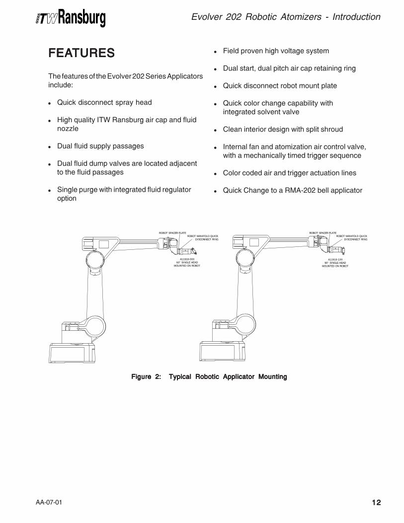
Figure 2: Typical Robotic Applicator MountingFigure 2: Typical Robotic Applicator MountingFigure 2: Typical Robotic Applicator MountingFigure 2: Typical Robotic Applicator MountingFigure 2: Typical Robotic Applicator Mounting
FEAFEAFEAFEAFEATURESTURESTURESTURESTURES
The features of the Evolver 202 Series Applicatorsinclude:
! Quick disconnect spray head
! High quality ITW Ransburg air cap and fluidnozzle
! Dual fluid supply passages
! Dual fluid dump valves are located adjacentto the fluid passages
! Single purge with integrated fluid regulatoroption
! Field proven high voltage system
! Dual start, dual pitch air cap retaining ring
! Quick disconnect robot mount plate
! Quick color change capability withintegrated solvent valve
! Clean interior design with split shroud
! Internal fan and atomization air control valve,with a mechanically timed trigger sequence
! Color coded air and trigger actuation lines
! Quick Change to a RMA-202 bell applicator
ROBOT MANIFOLD QUICKDISCONNECT RING
ROBOT SPACER PLATE
A11918-0XX60° SINGLE HEAD
MOUNTED ON ROBOT
ROBOT MANIFOLD QUICKDISCONNECT RING
ROBOT SPACER PLATE
A11918-1XX90° SINGLE HEAD
MOUNTED ON ROBOT
AA-07-011313131313
Evolver 202 Robotic Atomizers - Introduction
A1A1A1A1A11918-XXX EVOL1918-XXX EVOL1918-XXX EVOL1918-XXX EVOL1918-XXX EVOLVERVERVERVERVER
SPRASPRASPRASPRASPRAYYYYY APPLICA APPLICA APPLICA APPLICA APPLICATTTTTOROROROROR
ASSEMBLASSEMBLASSEMBLASSEMBLASSEMBLYYYYY
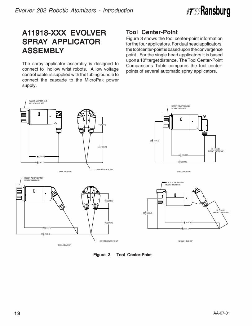
The spray applicator assembly is designed toconnect to hollow wrist robots. A low voltagecontrol cable is supplied with the tubing bundle toconnect the cascade to the MicroPak powersupply.
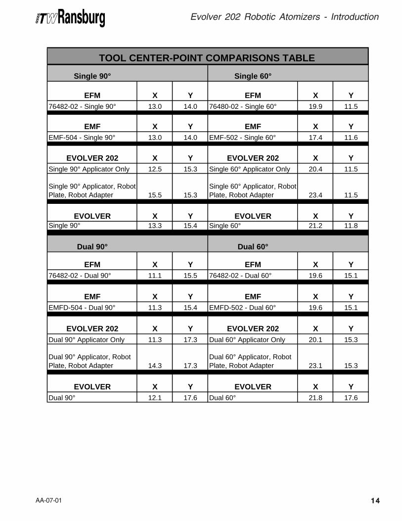
Figure 3: Tool Center-PointFigure 3: Tool Center-PointFigure 3: Tool Center-PointFigure 3: Tool Center-PointFigure 3: Tool Center-Point
TTTTTool Center-Pointool Center-Pointool Center-Pointool Center-Pointool Center-PointFigure 3 shows the tool center-point informationfor the four applicators. For dual head applicators,the tool center-point is based upon the convergencepoint. For the single head applicators it is basedupon a 10" target distance. The Tool Center-PointComparisons Table compares the tool center-points of several automatic spray applicators.
DUAL HEAD 90° SINGLE HEAD 90°
SINGLE HEAD 60°
DUAL HEAD 60°
1414 [363.1]
6 [152.4]
1114 [285.6]
1514 [386.5]
10 [254.0]TARGET DISTANCE
1512 [394.5]
558 [143.3]
958 [245.8]
2338 [595.2]
2318 [587.5]
10 [254.0]TARGET DISTANCE111
2 [291.8]
1114 [287.0]
1212 [318.8]
2038 [518.4]
2018 [511.4]
CONVERGENCE POINT
CONVERGENCE POINT
ROBOT ADAPTER ANDMOUNTING PLATE
ROBOT ADAPTER ANDMOUNTING PLATE
ROBOT ADAPTER ANDMOUNTING PLATE
ROBOT ADAPTER ANDMOUNTING PLATE
AA-07-01
Evolver 202 Robotic Atomizers - Introduction
1414141414
TOOL CENTER-POINT COMPARISONS TABLE
Single 90° Single 60°
EFM X Y EFM X Y76482-02 - Single 90° 13.0 14.0 76480-02 - Single 60° 19.9 11.5
EMF X Y EMF X YEMF-504 - Single 90° 13.0 14.0 EMF-502 - Single 60° 17.4 11.6
EVOLVER 202 X Y EVOLVER 202 X YSingle 90° Applicator Only 12.5 15.3 Single 60° Applicator Only 20.4 11.5
Single 90° Applicator, Robot Plate, Robot Adapter 15.5 15.3
Single 60° Applicator, Robot Plate, Robot Adapter 23.4 11.5
EVOLVER X Y EVOLVER X YSingle 90° 13.3 15.4 Single 60° 21.2 11.8
Dual 90° Dual 60°
EFM X Y EFM X Y76482-02 - Dual 90° 11.1 15.5 76482-02 - Dual 60° 19.6 15.1
EMF X Y EMF X YEMFD-504 - Dual 90° 11.3 15.4 EMFD-502 - Dual 60° 19.6 15.1
EVOLVER 202 X Y EVOLVER 202 X YDual 90° Applicator Only 11.3 17.3 Dual 60° Applicator Only 20.1 15.3
Dual 90° Applicator, Robot Plate, Robot Adapter 14.3 17.3
Dual 60° Applicator, Robot Plate, Robot Adapter 23.1 15.3
EVOLVER X Y EVOLVER X YDual 90° 12.1 17.6 Dual 60° 21.8 17.6
AA-07-01
INSTINSTINSTINSTINSTALLAALLAALLAALLAALLATIONTIONTIONTIONTION
1515151515
Evolver 202 Robotic Atomizers - Installation
EVOLEVOLEVOLEVOLEVOLVER 202 ROBOTICVER 202 ROBOTICVER 202 ROBOTICVER 202 ROBOTICVER 202 ROBOTICAAAAATTTTTOMIZER INSTOMIZER INSTOMIZER INSTOMIZER INSTOMIZER INSTALLAALLAALLAALLAALLATIONTIONTIONTIONTION
This information is intended ONLYONLYONLYONLYONLY to indicate thegeneral installation parameters of this productand, where applicable, its working relationship toother ITW Ransburg system components in typi-cal use. Each installation is unique and should bedirected by an authorized ITW Ransburg repre-sentative or conducted from the ITW Ransburginstallation drawings provided for your particularinstallation.
POWER SUPPLPOWER SUPPLPOWER SUPPLPOWER SUPPLPOWER SUPPLYYYYY
ASSEMBLASSEMBLASSEMBLASSEMBLASSEMBLYYYYY
Refer to the most current Power Supply Unitmanuals for complete information regarding powersupply installation.
• MicroPak Control Unit (LECU5004)(for non-FM installations)
• Stand-alone control/power supply unit (A10406) (for FM installations)
• MicroPak Control Unit (LECU5004-31)(for FM installations)
> The power supply MUSTMUSTMUSTMUSTMUST be located outside
the HAZARDOUSHAZARDOUSHAZARDOUSHAZARDOUSHAZARDOUS area (Reference OSHA,NFPA-33, and your insurance company re-quirements.)
> User should be aware of, and adhere to, all
local fire codes and ordinances.
> The user MUSTMUSTMUSTMUSTMUST provide a properly fused
disconnect between the power source and thepower supply which complies with appropriatecodes.
> Fluid supply must be grounded per NFPA-
33.
W A R N I N GW A R N I N GW A R N I N GW A R N I N GW A R N I N G!!!!!
AA-07-01 1616161616
Evolver 202 Robotic Atomizers - Installation
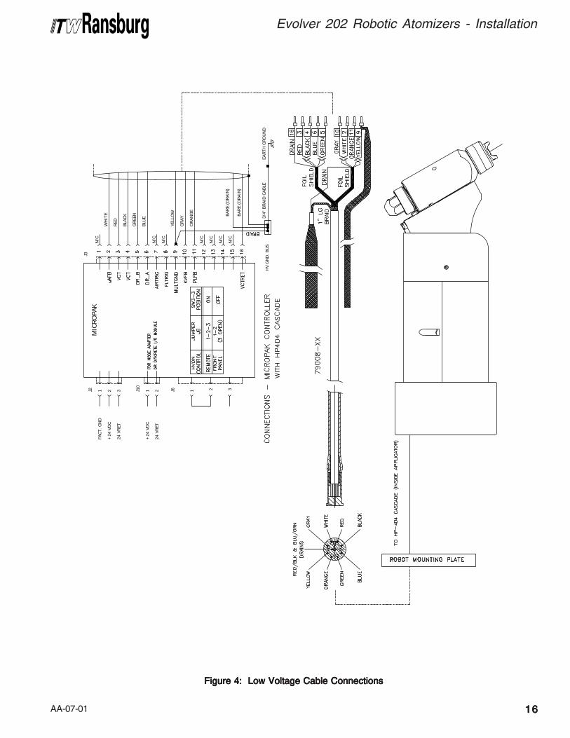
Figure 4: Low Voltage Cable ConnectionsFigure 4: Low Voltage Cable ConnectionsFigure 4: Low Voltage Cable ConnectionsFigure 4: Low Voltage Cable ConnectionsFigure 4: Low Voltage Cable Connections
HV G
ND
. BU
S
32J6 1J10
J2
+24
VD
C
24 V
RET
1 2
FACT.
GN
D
+24
VD
C
24 V
RET
321M
ICRO
PAK
BAR
E (D
RAI
N)
BAR
E (D
RAI
N)
YELL
OW
ORAN
GE
N/C
N/C
N/C
N/C
GRAY
BLACK
N/C
N/C
GREE
N
BLU
E
N/C
J3
WH
ITE
RED
3/4"
BR
AID
CABL
EEA
RTH
GRO
UN
D
AA-07-011717171717
Evolver 202 Robotic Atomizers - Installation
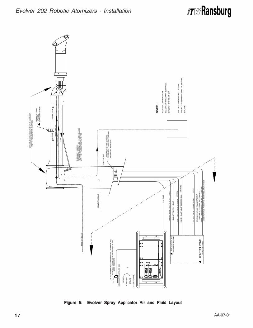
Figure 5: Evolver Spray Applicator Air and Fluid LayoutFigure 5: Evolver Spray Applicator Air and Fluid LayoutFigure 5: Evolver Spray Applicator Air and Fluid LayoutFigure 5: Evolver Spray Applicator Air and Fluid LayoutFigure 5: Evolver Spray Applicator Air and Fluid Layout
SHAP
ING
AIR
/ATO
MIZ
ATIO
N A
IR
SEAL
AIR
/FAN
AIR
BEARIN
G A
IR/P
AIN
T TR
IGG
ER
SOLV
ENT
VALV
E TR
IGG
ER S
IGN
AL
LEAVE
TU
BIN
G S
LACK
IN T
HE
WRIS
T AN
D E
LBO
WAREA
TO
RED
UCE
RO
TATI
ON
STR
ESS. TR
IGG
ER S
OLE
NO
ID(I
F U
SED
)SU
PPLI
ED B
Y O
THER
S
(MAIN
AIR
IF
EXTE
RN
AL T
RIG
GER
USE
D)
INSI
DE
ENCLO
SURE
3/4"
HV G
ND
BRAID
(D
EARBO
RN
#91
234
OR E
QU
IVAL
ANT)
ATT
ACH
TO
ISO
LATE
D H
.V. G
ND
(FO
R M
ICRO
PAK)
ATT
ACH
TO
PAN
EL
GRO
UN
D
AC N
EUTR
AL
120V
AC
BUIL
DIN
G S
TEEL
/GRO
UN
D R
OD
L.V. CAB
LE
CON
TRO
L PA
NEL
CO
NTR
OLS
BY
OTH
ERS
AN
ALO
G S
IGN
AL A
ND
TRAN
SDU
CER
REQ
UIR
ED
IF U
SIN
G A
CAP
CLE
ANER
TH
E
IF A
CAP
CLE
AN
ER I
S U
SED
IT
MU
ST B
E
VEN
TED
TO
ATM
OSP
HER
E W
ITH
OU
T PR
ESSU
RE
DIR
ECTL
Y IN
TO T
HE
AIR C
AP.
SOLV
ENT/
AIR
SH
OU
LD N
OT
BE S
PRAY
ED
BUIL
D U
P.
LUBR
ICATE
TH
E TU
BIN
G B
UN
DLE
EXCES
SIVEL
Y TO
EAS
E IN
STAL
LATI
ON
AND
EXT
END
TU
BIN
G L
IFE.
(BLU
E)
(GRAY
)
(YEL
LOW
)
(BLU
E)
PAIN
T 1
TRIG
GER
VAL
VE S
IGN
AL
PAIN
T 1
DU
MP
VALV
E TR
IGG
ER S
IGN
AL(GREE
N)
(ORAN
GE)
SOLV
ENT
SUPP
LY
WIT
H T
HE
ITW
EQ
UIP
MEN
T PU
RCH
ASE.
FOR R
EFER
ENCE
ON
LY A
ND
IS
NO
T IN
CLU
DED
THE
RO
BOT
IS S
HO
WN
DU
MP
SOLV
ENT
INBO
UN
D
DU
MP
LIN
E O
UT
PAIN
T SU
PPLY
1
PAIN
T 1
INBO
UN
D
PAIN
T 2
TRIG
GER
/PEG
ULA
TOR
PIL
OT
(USE
D F
OR D
UAL
PU
RG
E AN
D R
EGU
LATE
D A
PPLI
CAT
ION
S)
(NATU
RAL
)
AA-07-01 1818181818
Evolver 202 Robotic Atomizers - Installation
APPLICAAPPLICAAPPLICAAPPLICAAPPLICATTTTTOR ANDOR ANDOR ANDOR ANDOR AND
MANIFOLD ASSEMBLMANIFOLD ASSEMBLMANIFOLD ASSEMBLMANIFOLD ASSEMBLMANIFOLD ASSEMBLYYYYY(See Figures 4, 5, and 6)(See Figures 4, 5, and 6)(See Figures 4, 5, and 6)(See Figures 4, 5, and 6)(See Figures 4, 5, and 6)
The tubing, hose, and low voltage cable comebundled from the factory. Pull the bundle throughthe robot spacer plate and robot wrist carefully toprevent any cuts on the cable or hoses. Use thesix (6) socket head cap screws (76566-24C)included with the rear manifold tubing assembly toattach the rear manifold assembly (79106 orA10892) to the robot spacer plate (see Table 1).
Connect each signal line as required per "SignalIdentification Tables (English and Metric) TubingBundles" in the "Installation" section.
Robot Spacer PlateRobot Spacer PlateRobot Spacer PlateRobot Spacer PlateRobot Spacer PlateThe robot spacer plate is included with the robotmanifold assembly to increase life of the tubingbundle. The extra spacing it provides increasesthe bend radius of the tubes and decreases thehose or cable stress at the connector.
There is only one way the spacer plate may beassembled to the mounting plate. The spacerplate has an alignment pin that may only engagein one hole position in the robot mount plate. Thisprovides the final position to top dead center of therobot.
Six robot spacer plates shown in Table 1 areavailable for this product.
LOW VOLLOW VOLLOW VOLLOW VOLLOW VOLTTTTTAGE CABLEAGE CABLEAGE CABLEAGE CABLEAGE CABLE
INSTINSTINSTINSTINSTALLAALLAALLAALLAALLATIONSTIONSTIONSTIONSTIONS
For installations utilizing the LECU5004-XXMicroPak power supply, connect the low voltagecable (79008-XX) from the robot manifold assemblyto the LECU5004-XX MicroPak controller orjunction box. If connecting to a junction box, usea junction cable (77062-XX) to make the connectionfrom the junction box to the LECU5004-XXMicroPak. Make connections as shown in Figure4.
For installations utilizing the A10406-XX EvolverMicroPak power supply, connect the low voltagecable (A11353-XX or A11356-XX) from the robotmanifold assembly or junction box to the receptacleon the rear of the A10406-XX power supply. Tomaintain FM Approval, this cable must be securedto the stress relief bar on the rear of the powersupply. (See A10406-XX Evolver MicroPakPower Supply manual for further information onconnecting the low voltage cable.)
> If the length of the fan or atomization
air lines exceeds 30 ft. (10m), the linesmust be upsized to 1/2" ID (12mm formetric).
NOTENOTENOTENOTENOTE
> For the dipswitch settings for the
Evolver 202, reference the currentMicroPak service manual.
NOTENOTENOTENOTENOTE
> Leave 12-24 inches (.30m-.61m) of
extra length on all lines to prevent ex-treme tension being applied to these linesduring robot movement. This increasestubing bundle life.
NOTENOTENOTENOTENOTE
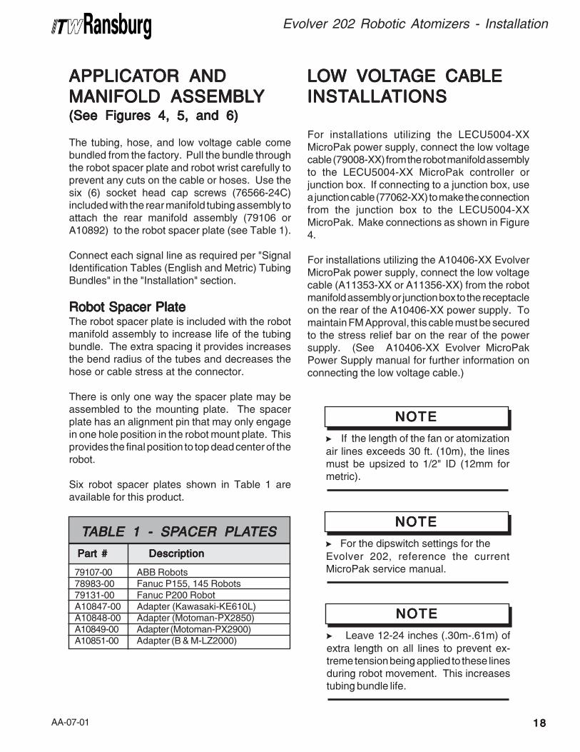
79107-00 ABB Robots78983-00 Fanuc P155, 145 Robots79131-00 Fanuc P200 RobotA10847-00 Adapter (Kawasaki-KE610L)A10848-00 Adapter (Motoman-PX2850)A10849-00 Adapter (Motoman-PX2900)A10851-00 Adapter (B & M-LZ2000)
Part # Part # Part # Part # Part # Description Description Description Description Description
TTTTTABLE 1 - SPABLE 1 - SPABLE 1 - SPABLE 1 - SPABLE 1 - SPACER PLAACER PLAACER PLAACER PLAACER PLATESTESTESTESTES
AA-07-011919191919
Evolver 202 Robotic Atomizers - Installation
> Install and route the hoses and cable so that
they are NOTNOTNOTNOTNOT exposed to temperatures inexcess of 120° F. Ensure that all hose andcable bends are NOT LESS THANNOT LESS THANNOT LESS THANNOT LESS THANNOT LESS THAN a 6 inch(15cm) radius and are not subjected to morethan 360° of torsional twist. Failure to complywith these parameters could cause equipmentmalfunctions that might create HAZARDOUSHAZARDOUSHAZARDOUSHAZARDOUSHAZARDOUS
CONDITIONS!CONDITIONS!CONDITIONS!CONDITIONS!CONDITIONS!
W A R N I N GW A R N I N GW A R N I N GW A R N I N GW A R N I N G!!!!!
> If a non-explosion proof junction box/termi-
nal strip is used, it must be located outside thehazardous area.
W A R N I N GW A R N I N GW A R N I N GW A R N I N GW A R N I N G!!!!!
> Do not exceed 100' combined length of the
low voltage cables.
C A U T I O NC A U T I O NC A U T I O NC A U T I O NC A U T I O N!!!!! NOTESNOTESNOTESNOTESNOTES
AA-07-01 2020202020
Evolver 202 Robotic Atomizers - Installation
Tubing MaterialTubing MaterialTubing MaterialTubing MaterialTubing Material Tubing SizeTubing SizeTubing SizeTubing SizeTubing Size
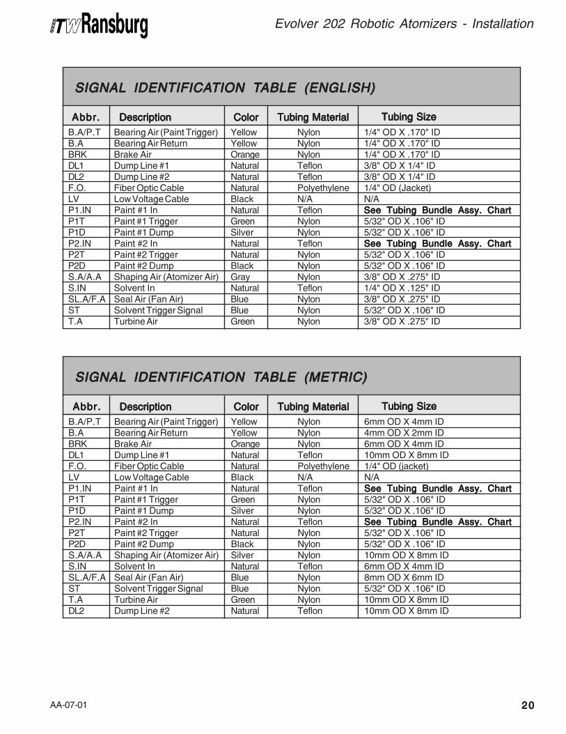
B.A/P.T Bearing Air (Paint Trigger) Yellow Nylon 1/4" OD X .170" IDB.A Bearing Air Return Yellow Nylon 1/4" OD X .170" IDBRK Brake Air Orange Nylon 1/4" OD X .170" IDDL1 Dump Line #1 Natural Teflon 3/8" OD X 1/4" IDDL2 Dump Line #2 Natural Teflon 3/8" OD X 1/4" IDF.O. Fiber Optic Cable Natural Polyethylene 1/4" OD (Jacket)LV Low Voltage Cable Black N/A N/AP1.IN Paint #1 In Natural Teflon See Tubing Bundle Assy. ChartSee Tubing Bundle Assy. ChartSee Tubing Bundle Assy. ChartSee Tubing Bundle Assy. ChartSee Tubing Bundle Assy. ChartP1T Paint #1 Trigger Green Nylon 5/32" OD X .106" IDP1D Paint #1 Dump Silver Nylon 5/32" OD X .106" IDP2.IN Paint #2 In Natural Teflon See Tubing Bundle Assy. ChartSee Tubing Bundle Assy. ChartSee Tubing Bundle Assy. ChartSee Tubing Bundle Assy. ChartSee Tubing Bundle Assy. ChartP2T Paint #2 Trigger Natural Nylon 5/32" OD X .106" IDP2D Paint #2 Dump Black Nylon 5/32" OD X .106" IDS.A/A.A Shaping Air (Atomizer Air) Gray Nylon 3/8" OD X .275" IDS.IN Solvent In Natural Teflon 1/4" OD X .125" IDSL.A/F.A Seal Air (Fan Air) Blue Nylon 3/8" OD X .275" IDST Solvent Trigger Signal Blue Nylon 5/32" OD X .106" IDT.A Turbine Air Green Nylon 3/8" OD X .275" ID
SIGNALSIGNALSIGNALSIGNALSIGNAL IDENTIFICA IDENTIFICA IDENTIFICA IDENTIFICA IDENTIFICATION TTION TTION TTION TTION TABLE (ENGLISH)ABLE (ENGLISH)ABLE (ENGLISH)ABLE (ENGLISH)ABLE (ENGLISH)
Abbr.Abbr.Abbr.Abbr.Abbr. DescriptionDescriptionDescriptionDescriptionDescription ColorColorColorColorColor
Tubing MaterialTubing MaterialTubing MaterialTubing MaterialTubing Material Tubing SizeTubing SizeTubing SizeTubing SizeTubing Size
B.A/P.T Bearing Air (Paint Trigger) Yellow Nylon 6mm OD X 4mm IDB.A Bearing Air Return Yellow Nylon 4mm OD X 2mm IDBRK Brake Air Orange Nylon 6mm OD X 4mm IDDL1 Dump Line #1 Natural Teflon 10mm OD X 8mm IDF.O. Fiber Optic Cable Natural Polyethylene 1/4" OD (jacket)LV Low Voltage Cable Black N/A N/AP1.IN Paint #1 In Natural Teflon See Tubing Bundle Assy. ChartSee Tubing Bundle Assy. ChartSee Tubing Bundle Assy. ChartSee Tubing Bundle Assy. ChartSee Tubing Bundle Assy. ChartP1T Paint #1 Trigger Green Nylon 5/32" OD X .106" IDP1D Paint #1 Dump Silver Nylon 5/32" OD X .106" IDP2.IN Paint #2 In Natural Teflon See Tubing Bundle Assy. ChartSee Tubing Bundle Assy. ChartSee Tubing Bundle Assy. ChartSee Tubing Bundle Assy. ChartSee Tubing Bundle Assy. ChartP2T Paint #2 Trigger Natural Nylon 5/32" OD X .106" IDP2D Paint #2 Dump Black Nylon 5/32" OD X .106" IDS.A/A.A Shaping Air (Atomizer Air) Silver Nylon 10mm OD X 8mm IDS.IN Solvent In Natural Teflon 6mm OD X 4mm IDSL.A/F.A Seal Air (Fan Air) Blue Nylon 8mm OD X 6mm IDST Solvent Trigger Signal Blue Nylon 5/32" OD X .106" IDT.A Turbine Air Green Nylon 10mm OD X 8mm IDDL2 Dump Line #2 Natural Teflon 10mm OD X 8mm ID
SIGNALSIGNALSIGNALSIGNALSIGNAL IDENTIFICA IDENTIFICA IDENTIFICA IDENTIFICA IDENTIFICATION TTION TTION TTION TTION TABLE (METRIC)ABLE (METRIC)ABLE (METRIC)ABLE (METRIC)ABLE (METRIC)
Abbr.Abbr.Abbr.Abbr.Abbr. DescriptionDescriptionDescriptionDescriptionDescription ColorColorColorColorColor
AA-07-012121212121
Evolver 202 Robotic Atomizers - Installation
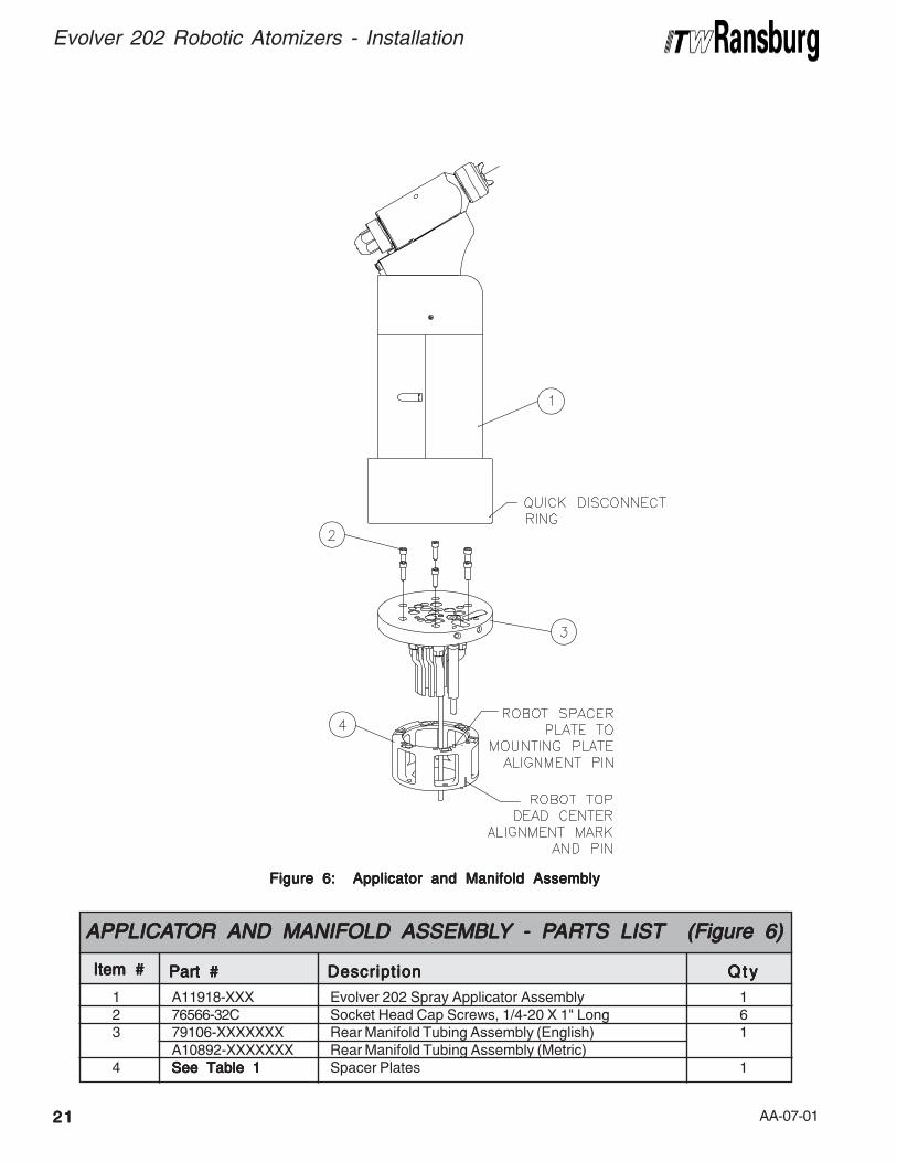
Figure 6: Applicator and Manifold AssemblyFigure 6: Applicator and Manifold AssemblyFigure 6: Applicator and Manifold AssemblyFigure 6: Applicator and Manifold AssemblyFigure 6: Applicator and Manifold Assembly
1 A11918-XXX Evolver 202 Spray Applicator Assembly 12 76566-32C Socket Head Cap Screws, 1/4-20 X 1" Long 63 79106-XXXXXXX Rear Manifold Tubing Assembly (English) 1
A10892-XXXXXXX Rear Manifold Tubing Assembly (Metric)4 See Table 1See Table 1See Table 1See Table 1See Table 1 Spacer Plates 1
Item #Item #Item #Item #Item #
APPLICAAPPLICAAPPLICAAPPLICAAPPLICATTTTTOR AND MANIFOLDOR AND MANIFOLDOR AND MANIFOLDOR AND MANIFOLDOR AND MANIFOLD ASSEMBL ASSEMBL ASSEMBL ASSEMBL ASSEMBLYYYYY - P- P- P- P- PARARARARARTS LISTTS LISTTS LISTTS LISTTS LIST (Figure 6) (Figure 6) (Figure 6) (Figure 6) (Figure 6)
Part #Part #Part #Part #Part # DescriptionDescriptionDescriptionDescriptionDescription Q t yQ t yQ t yQ t yQ t y
AA-07-01 2222222222
Evolver 202 Robotic Atomizers - Installation
SPRASPRASPRASPRASPRAYYYYY / BELL / BELL / BELL / BELL / BELL
APPLICAAPPLICAAPPLICAAPPLICAAPPLICATTTTTOROROROROR
TRIGGERINGTRIGGERINGTRIGGERINGTRIGGERINGTRIGGERING
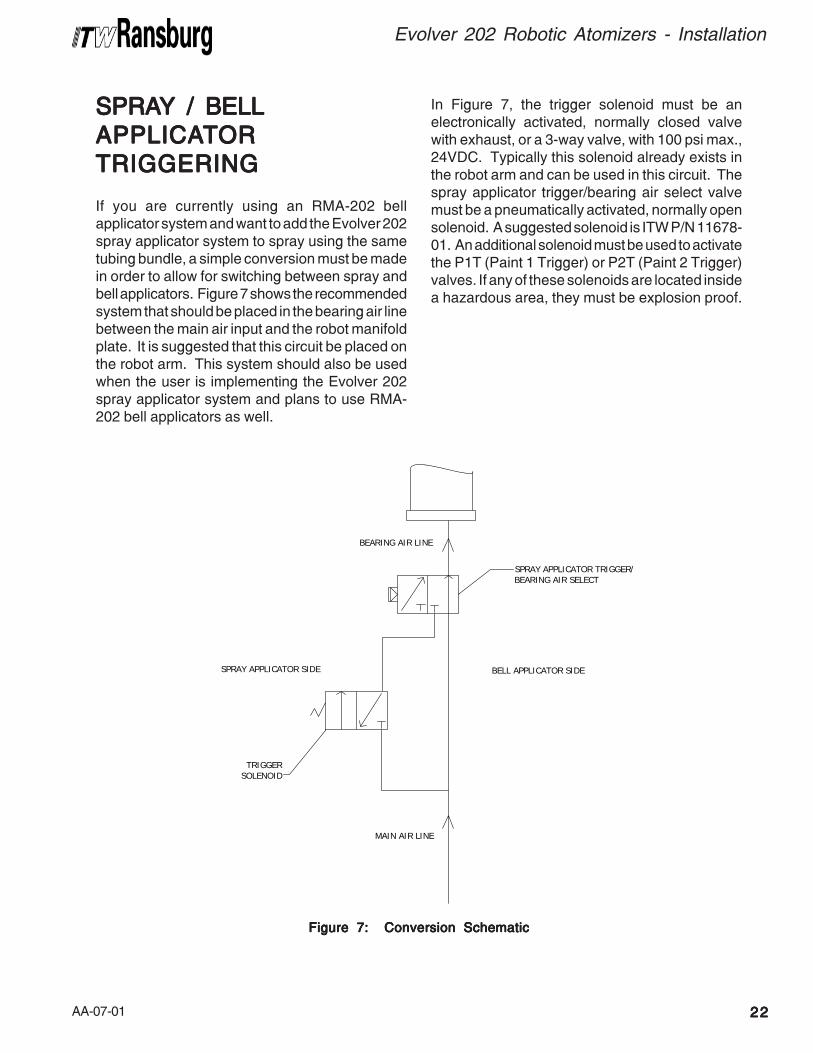
If you are currently using an RMA-202 bellapplicator system and want to add the Evolver 202spray applicator system to spray using the sametubing bundle, a simple conversion must be madein order to allow for switching between spray andbell applicators. Figure 7 shows the recommendedsystem that should be placed in the bearing air linebetween the main air input and the robot manifoldplate. It is suggested that this circuit be placed onthe robot arm. This system should also be usedwhen the user is implementing the Evolver 202spray applicator system and plans to use RMA-202 bell applicators as well.
Figure 7: Conversion SchematicFigure 7: Conversion SchematicFigure 7: Conversion SchematicFigure 7: Conversion SchematicFigure 7: Conversion Schematic
In Figure 7, the trigger solenoid must be anelectronically activated, normally closed valvewith exhaust, or a 3-way valve, with 100 psi max.,24VDC. Typically this solenoid already exists inthe robot arm and can be used in this circuit. Thespray applicator trigger/bearing air select valvemust be a pneumatically activated, normally opensolenoid. A suggested solenoid is ITW P/N 11678-01. An additional solenoid must be used to activatethe P1T (Paint 1 Trigger) or P2T (Paint 2 Trigger)valves. If any of these solenoids are located insidea hazardous area, they must be explosion proof.
MAIN AIR LINE
SPRAY APPLICATOR SIDE BELL APPLICATOR SIDE
TRIGGERSOLENOID
SPRAY APPLICATOR TRIGGER/BEARING AIR SELECT
BEARING AIR LINE
AA-07-012323232323
Evolver 202 Robotic Atomizers - Operation
OPERAOPERAOPERAOPERAOPERATIONTIONTIONTIONTION
SPRASPRASPRASPRASPRAYYYYY APPLICA APPLICA APPLICA APPLICA APPLICATTTTTOROROROROR
CONTROLSCONTROLSCONTROLSCONTROLSCONTROLS
Atomization Air (SA/AA) /Atomization Air (SA/AA) /Atomization Air (SA/AA) /Atomization Air (SA/AA) /Atomization Air (SA/AA) /Fan Air (SL.A/FFan Air (SL.A/FFan Air (SL.A/FFan Air (SL.A/FFan Air (SL.A/F.A).A).A).A).A)The atomization and fan air are turned on by thetrigger line and are controlled by an internal airvalve located in the applicator head. During nor-mal operation with applicator triggered off, there isa slight bleed of air through the atomization port.
Atomizing AirAtomizing AirAtomizing AirAtomizing AirAtomizing AirAdjustments are made through the robot PLC or amanually adjustable air regulator. The lowest airpressure required to break up the paint should beused. Lower atomizing air pressures result in lessoverspray and increased transfer efficiency.
Fan AirFan AirFan AirFan AirFan AirAdjusting the fan air increases or decreases thesize of the spray pattern. Increasing pressureincreases pattern size. Pattern adjustment shouldbe made to suit the size and shape of the objectbeing painted. This adjustment is made throughthe robot PLC or a manually adjustable air regula-tor.
Air cap atomization and fan pressures should beset and recorded using an air cap test kit. Thisprovides a consistent measurement, so initialsettings may be duplicated at any time. (See"Accessories" in the "Parts Identification" sec-tion.)
FLUID VFLUID VFLUID VFLUID VFLUID VALALALALALVE CONTROLSVE CONTROLSVE CONTROLSVE CONTROLSVE CONTROLS
TTTTTriggerriggerriggerriggerrigger, Dump, and Solvent, Dump, and Solvent, Dump, and Solvent, Dump, and Solvent, Dump, and Solvent(S(S(S(S(See ee ee ee ee FFFFFigureigureigureigureigure 8) 8) 8) 8) 8)The fluid valves in the Evolver 202 are actuated byan air signal. The air pressure must exceed 70 psi(4.8 bar) to assure proper actuation of the valve.Applying air to the valve actuator turns on the fluidflow for that valve.
The paint valve controls the paint flow to theapplicator. When actuated, paint flows throughthe valve to the coiled fluid tube and into the sprayhead.
The dump valve controls the paint flow through thedump line. When actuated, paint flow is directed tothe dump return line. This provides a method ofrapidly removing paint from the incoming line forcleaning and/or color change. Normally, the dumpvalve is not actuated at the same time as the paintvalve since the paint valve is intended to cause thefluid to flow to the applicator head at the prescribedinput pressure.
The solvent valve controls the flow of cleaningsolvent to the applicator. When actuated, solventflows through the fluid tube and into the sprayhead. The solvent valve is not triggered at thesame time as the paint trigger valve to preventsolvent from flowing backward into the paint line.
HVLPHVLPHVLPHVLPHVLP SPRA SPRA SPRA SPRA SPRAYYYYY
The Evolver 202 HVLP models, when properlyset-up, are designed to provide maximum transferefficiency by limiting air cap pressures to 10 psi(0.7 bar) (in the U.S., this complies with rulesissued by SCAQMD and other air qualityauthorities). Air cap pressures should be measuredwith an optional air cap test kit. (See "Accessories"in the "Parts Identification" section.)
> For HVLP operation (max. 10 psi, 0.7
bar cap pressure), DO NOTDO NOTDO NOTDO NOTDO NOT exceed theair inlet pressure, which was read at thegun base before the tubing manifolds,given as follows:
PSIPSIPSIPSIPSI (Bar)(Bar)(Bar)(Bar)(Bar) CAP #CAP #CAP #CAP #CAP #42 (2.9) 48-142 (2.9) 481-1
NOTENOTENOTENOTENOTE
AA-07-01 2424242424
Evolver 202 Robotic Atomizers - Operation
When the cleaning cycle with solvent is complete,an air purge for several seconds is recommendedto clean and dry the ID of the dump line hose.
Paint VPaint VPaint VPaint VPaint ViscosityiscosityiscosityiscosityiscosityThe applicator is capable of atomizing paint ofmost any desired viscosity. It is recommended tokeep the material viscosity as low as possible.This allows spraying at lower fan and atomizationair pressures which result in less overspray andhigher transfer efficiency.
Fluid Flow RateFluid Flow RateFluid Flow RateFluid Flow RateFluid Flow RateFluid flow is adjusted through the robot PLC byvarying the pilot pressure to either an exterior orthe on-board fluid regulator within the spray appli-cator. Fluid pressures from the circulating systemmay exceed the maximum fluid pressure rating ofthe Evolver 202 applicator. Because of these highfluid pressures, a manual step-down fluid regula-tor must be used.
Applicator TApplicator TApplicator TApplicator TApplicator Trigger Control Airrigger Control Airrigger Control Airrigger Control Airrigger Control AirThe Evolver applicators require a minimum of 70psig trigger control air pressure to ensure properoperation of the applicator piston.
Electrostatic VElectrostatic VElectrostatic VElectrostatic VElectrostatic VoltageoltageoltageoltageoltageUnder no load conditions, the maximum voltagelimit for these spray applicators is 100 kV. Somepainting operations may require different voltagesettings to obtain optimum transfer efficiencies. IfFaraday cage areas are predominant on the itembeing painted, a lower voltage setting would aid incoating these areas.
When not spraying, it is recommended to set backvoltage to 30-40 kV or off between target parts.
> Most paints and solvents, including those
listed in "Polar & Non-Polar Solvents Chart" inthe "Maintenance" section, are toxic to a cer-tain degree and flammable or combustible.Use them only in a well ventilated atmosphere.Use protective equipment as required in theMaterial Safety Data Sheet supplied with thesubstance.
W A R N I N GW A R N I N GW A R N I N GW A R N I N GW A R N I N G!!!!!
> Failure to turn voltage OFF during color
change sequence when solvent is flowingthrough the fluid nozzle, could cause a fireor explosion.
W A R N I N GW A R N I N GW A R N I N GW A R N I N GW A R N I N G!!!!!
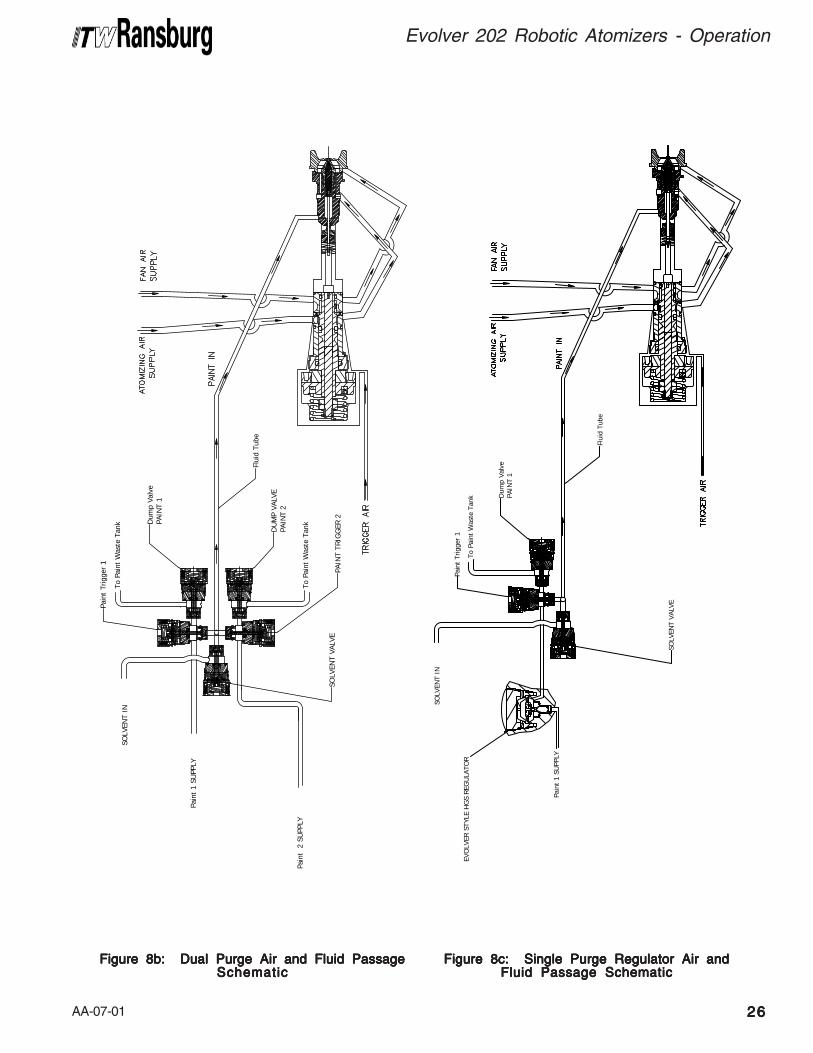
DUALDUALDUALDUALDUAL PURGE SPRA PURGE SPRA PURGE SPRA PURGE SPRA PURGE SPRAYINGYINGYINGYINGYING
The Evolver 202 applicator system has optionaldual purge capability. This means the applicatorcan continue to spray paint, at voltage, while side"B" or "Paint 2" is being flushed or cleaned. Thesolvent valve opens and cleans from the coiledfluid tube and up through the head and out thenozzle. A second color is then loaded through the"B" side. Side "A" is then color changed throughthe "A" side feed lines to the applicator and valveports, while the waste from side "A" is exitedthrough the dump lines. To operate in the dualpurge mode, two (2) separate color valvetwo (2) separate color valvetwo (2) separate color valvetwo (2) separate color valvetwo (2) separate color valvesystems or ITW MCV2 Dual Purge must besystems or ITW MCV2 Dual Purge must besystems or ITW MCV2 Dual Purge must besystems or ITW MCV2 Dual Purge must besystems or ITW MCV2 Dual Purge must beinstalled.installed.installed.installed.installed.
When the target part is finished and a color changeis desired, ensure voltage is turned off.
> If a 0 kV command is sent to the
MicroPak, a feedback fault will occur.
NOTENOTENOTENOTENOTE
Sometimes, depending upon target carrier spac-ing, higher setback voltages may be required. Theramp-up time for the HP-404 cascade (0-100 kV)is approximately 3 seconds.
The MicroPak voltage ramp-down works at a rateof 33 kV/sec.
AA-07-01
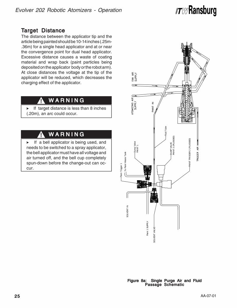
TTTTTarget Distancearget Distancearget Distancearget Distancearget DistanceThe distance between the applicator tip and thearticle being painted should be 10-14 inches (.25m-.36m) for a single head applicator and at or nearthe convergence point for dual head applicator.Excessive distance causes a waste of coatingmaterial and wrap back (paint particles beingdeposited on the applicator body or the robot arm).At close distances the voltage at the tip of theapplicator will be reduced, which decreases thecharging effect of the applicator.
> If target distance is less than 8 inches
(.20m), an arc could occur.
W A R N I N GW A R N I N GW A R N I N GW A R N I N GW A R N I N G!!!!!
2525252525
Evolver 202 Robotic Atomizers - Operation
Figure 8a: Single Purge Air and FluidFigure 8a: Single Purge Air and FluidFigure 8a: Single Purge Air and FluidFigure 8a: Single Purge Air and FluidFigure 8a: Single Purge Air and FluidPassage SchematicPassage SchematicPassage SchematicPassage SchematicPassage Schematic
> If a bell applicator is being used, and
needs to be switched to a spray applicator,the bell applicator must have all voltage andair turned off, and the bell cup completelyspun-down before the change-out can oc-cur.
W A R N I N GW A R N I N GW A R N I N GW A R N I N GW A R N I N G!!!!!
To P
aint
Was
te T
ank D
ump
Valv
ePA
INT
1
Pain
t Tr
igge
r 1
SOLV
ENT
VALV
E
Flui
d Tu
be
DU
MP
VALV
EPA
INT
2 (P
LUG
GED
)
PAIN
T TR
IGG
ER 2
(PL
UG
GED
)
SOLV
ENT
IN
Pain
t 1
SUPP
LY
AA-07-01 2626262626
Evolver 202 Robotic Atomizers - Operation
Figure 8b: Dual Purge Air and Fluid PassageFigure 8b: Dual Purge Air and Fluid PassageFigure 8b: Dual Purge Air and Fluid PassageFigure 8b: Dual Purge Air and Fluid PassageFigure 8b: Dual Purge Air and Fluid PassageSchematicSchematicSchematicSchematicSchematic
To P
aint
Was
te T
ank D
ump
Valv
ePA
INT
1
Pain
t Tr
igge
r 1
SOLV
ENT
VALV
E
Flui
d Tu
be
DU
MP
VALV
EPA
INT
2
PAIN
T TR
IGG
ER 2
SOLV
ENT
IN
Pain
t 1
SUPP
LY
Pain
t 2
SU
PPLY
To P
aint
Was
te T
ank
Figure 8c: Single Purge Regulator Air andFigure 8c: Single Purge Regulator Air andFigure 8c: Single Purge Regulator Air andFigure 8c: Single Purge Regulator Air andFigure 8c: Single Purge Regulator Air andFluid Passage SchematicFluid Passage SchematicFluid Passage SchematicFluid Passage SchematicFluid Passage Schematic
Flui
d Tu
be
To P
aint
Was
te T
ank D
ump
Valv
ePA
INT
1
Pain
t Tr
igge
r 1
SOLV
ENT
VAL
VE
SOLV
ENT
IN
Pain
t 1
SUPP
LY
EVO
LVER
STY
LE H
GS
REG
ULA
TOR
AA-07-012727272727
Evolver 202 Robotic Atomizers - Maintenance
MAINTENANCEMAINTENANCEMAINTENANCEMAINTENANCEMAINTENANCE
Good maintenance is essential to safe and pro-ductive operation. Schedules should be estab-lished by the user, based on the following generalinformation and observations of the initial produc-tion requirements. The ITW Ransburg mainte-nance and safety information should be madeavailable to each operator.
Normal fire protection measures are necessary,including proper storage of paints and solventsand the proper disposal of waste. Ready accessto appropriate fire extinguishing equipment is re-quired. For details, consult the appropriate NFPAsafety information and/or applicable country safetystandard.
ROUTINE MAINTENANCEROUTINE MAINTENANCEROUTINE MAINTENANCEROUTINE MAINTENANCEROUTINE MAINTENANCESCHEDULESCHEDULESCHEDULESCHEDULESCHEDULE
Follow these maintenance steps to extend the lifeof the spray applicator and ensure efficient opera-tion:
Several Times DailySeveral Times DailySeveral Times DailySeveral Times DailySeveral Times Daily1. Turn the MicroPak control unit OFFOFFOFFOFFOFF! Follow"Lockout/Tagout Procedures".
2. Inspect the fluid nozzle, air cap, and elec-trode wire for paint accumulation. Clean asfrequently as necessary. See "Procedures" inthe "Maintenance" section.
> An electrical discharge or spark may create
an electrical and/or fire hazard during mainte-nance. Do not clean or service the sprayapplicator with the power supply on. Verifythat the power supply has been locked out andtagged out per OSHA and/or your applicablecountry safety codes.
> Unexpected robot movement can be haz-
ardous. Do not adjust or repair the sprayapplicator when the robot is operating or wait-ing to start. The robot must be locked out andtagged out per OSHA and/or your applicablecountry safety codes.
> Solvents used for equipment flushing must
have flash point ratings equal to or greaterthan the flash point rating of the coating mate-rial. Solvents used for general cleaning musthave flash point ratings higher than 100°F(37.8°C).
> Never remove spray applicator head from
assembly while under pressure.
W A R N I N GW A R N I N GW A R N I N GW A R N I N GW A R N I N G!!!!!
> Take precautions to see that skin is not
punctured by sharp electrode.
W A R N I N GW A R N I N GW A R N I N GW A R N I N GW A R N I N G!!!!!
> Do not bend the applicator electrode while
wiping. Never immerse the applicator in sol-vents. This will cause damage to the electricalcomponents.
C A U T I O NC A U T I O NC A U T I O NC A U T I O NC A U T I O N!!!!!
Daily (Or at Shift Start)Daily (Or at Shift Start)Daily (Or at Shift Start)Daily (Or at Shift Start)Daily (Or at Shift Start)1. Turn the MicroPak control unit OFFOFFOFFOFFOFF and:
• Check within 20' (6.1 meters) of the point ofoperation (of the applicator) and remove orground ALLALLALLALLALL loose or ungrounded containers.
• Inspect workholders for accumulated coatingmaterials (remove such accumulations ifpresent). Ensure resistance to ground fromwork holder is less than 1 megohm.
• Check that the nozzle assembly is clean andundamaged. Ensure air caps are clean andundamaged.
AA-07-01 2828282828
Evolver 202 Robotic Atomizers - Maintenance
2. Turn the MicroPak control unit ONONONONON! Energizehigh voltage.
Shut-Down (Or at Shift End)Shut-Down (Or at Shift End)Shut-Down (Or at Shift End)Shut-Down (Or at Shift End)Shut-Down (Or at Shift End)1. Turn the MicroPak control unit OFF.
2. Flush the lines and allow the solvent to remainin the lines. See "Procedures" in the "Mainte-nance" section.
3. Wipe the applicator (including the air cap) androbot wrist with a cloth and a suitable, clean non-polar solvent.
WeeklyWeeklyWeeklyWeeklyWeekly1. Check the entire system for damage, leaks,and paint accumulation.
2. Clean the atomizer assembly.
3. Conduct a current output test. See "Proce-dures" in the "Maintenance" section.
PROCEDURESPROCEDURESPROCEDURESPROCEDURESPROCEDURESApplicator Cleaning/ServiceApplicator Cleaning/ServiceApplicator Cleaning/ServiceApplicator Cleaning/ServiceApplicator Cleaning/Service
(See Figure 9a and 9b)(See Figure 9a and 9b)(See Figure 9a and 9b)(See Figure 9a and 9b)(See Figure 9a and 9b)
1. Flush the paint supply line and the applicatorpaint passages using a solvent which is compat-ible with the material being sprayed. Continue toflush until all traces of paint are gone.
2. Turn off the solvent supply, actuate paint push-out air at color changer, and trigger the applicatorand P1T or P2T. Allow all of the fluid to drain fromthe spray applicator fluid passages.
3. Clean the exterior surfaces of the spray appli-cator with a solvent soaked rag. As long as theapplicator is intact, a polarpolarpolarpolarpolar solvent may be usedfor all cleaning, however, after cleaning, wipe off allsurfaces with a non-polarnon-polarnon-polarnon-polarnon-polar solvent to reduceconductive residue on the applicator's surface.(See "Polar & Non-Polar Solvents Chart" in the"Maintenance" section regarding proper solventselection.)
> Failure to use a non-polar solvent may
cause a decrease in voltage at the tip of theapplicator. This will significantly decreasetransfer efficiency.
C A U T I O NC A U T I O NC A U T I O NC A U T I O NC A U T I O N!!!!!
4. Remove end cap [1]. Removing the end capreleases tension on all internal spray head compo-nents. Remove needle spring [2] and valve spring[3], which are loose after removing the end cap.
5. Remove the air cap retainer [36] and air cap[35]. Soak in a non-polar solvent if necessary. Ifpaint remains in the air cap holes, clean with atoothpick or similar soft wood object. Air caps arebest cleaned in an ultrasonic cleaner.
6. Remove the air cap locator [33] and fluid tip [34].Clean using a non-polar solvent.
7. Tightly grip the plastic needle [6] and unscrewcounter-clockwise to remove the front electrodeneedle assembly. A short piece of H-2339 tubing(1/4" OD x 0.175" ID) pressed over the frontneedle will assist in unscrewing the assembly. Ifrequired, use needle nose pliers with maskingtape or duct tape. Carefully clean with a non-polarsolvent. Replace any parts that show signs ofwear or damage.
> Never attempt to clean the air cap holes
with a wire or other metal object. Doing somay damage the air cap, resulting in distor-tion of the spray pattern.
C A U T I O NC A U T I O NC A U T I O NC A U T I O NC A U T I O N!!!!!
> If using needle nose pliers to unscrew the
front needle, be very careful. Do not grip on thetapered sealing surface. If the pliers slip, theycould damage the tapered sealing surface ofthe needle.
C A U T I O NC A U T I O NC A U T I O NC A U T I O NC A U T I O N!!!!!
AA-07-012929292929
Evolver 202 Robotic Atomizers - Maintenance
8. Remove fluid nozzle [32] by unscrewingcounter-clockwise. Inspect o-ring [30] and allpassages for build up or damage. Clean or re-place as necessary. Lubricate and reinsert o-ring into applicator barrel and reinstall fluid nozzle.Torque fluid nozzle to 25 lbs•in (2.82 Nm).
> There should be a small gap between
the fluid nozzle and the applicator barrelafter tightening.
NOTENOTENOTENOTENOTE
9. After cleaning, insert the electrode assembly[31] back into the spray head assembly. ApplyLoctite #222, low strength (purple) thread-locker,to the threads of the electrode assembly beforereassembly.
10. Screw fluid tip [34] back into place. Handtighten first, then with a small wrench, tighten anadditional 30 degrees.
11. Replace air cap locator [33], air cap [35], andair cap retainer [36].
12. Apply a thin film of petroleum jelly to valve andneedle springs [2] and [3]. Install the springs backinto the end cap and the spray head assembly.
13. Screw end cap [1] back on.
Current Output TCurrent Output TCurrent Output TCurrent Output TCurrent Output Testestestestest1. Clean and blow out all fluid passages with non-conductive solvent.
2. Remove from robot and perform bench testusing a spare tubing bundle.
3. Turn the control unit power ONONONONON.
4. Activate high voltage and slowly approach theapplicator electrode with ground hook or wire.
5. Monitor the current output on MicroPak. Cur-rent should rise as ground approaches. Atapproximately 85 microamperes, the MicroPakwill shut off. The OVERCURRENTOVERCURRENTOVERCURRENTOVERCURRENTOVERCURRENT indicatorshould come on.
The spray head can be removed from assemblyas shown in Figure 9a for cleaning and service.
> The fluid tip [34] should always be
installed and tightened before installingthe needle and valve springs.
NOTENOTENOTENOTENOTE
> After tightening the fluid tip, always check
to see if the proper gap (1/16") between theneedle nuts and air valve stem occur, beforeinstallng the needle and valve springs backinto the head.
C A U T I O NC A U T I O NC A U T I O NC A U T I O NC A U T I O N!!!!!
Amyl AcetateMethyl Amyl Acetate
TolueneXylene
High Flash NapthaMineral Spirits
Non-Conductive (Non-Polar)Non-Conductive (Non-Polar)Non-Conductive (Non-Polar)Non-Conductive (Non-Polar)Non-Conductive (Non-Polar)
POLAR AND NON-POLAR SOLPOLAR AND NON-POLAR SOLPOLAR AND NON-POLAR SOLPOLAR AND NON-POLAR SOLPOLAR AND NON-POLAR SOLVENTSVENTSVENTSVENTSVENTS
Moderately ConductiveModerately ConductiveModerately ConductiveModerately ConductiveModerately Conductive Extremely Conductive (Polar)Extremely Conductive (Polar)Extremely Conductive (Polar)Extremely Conductive (Polar)Extremely Conductive (Polar)
Methyl Isobutyl KetoneEthyl Acetate
Methyl Ethyl KetoneButyl Carbitol
MethanolCarbitol
DiacetoneButyl Alcohol
AcetoneButyl Cellosolve

AA-07-01 3030303030
Evolver 202 Robotic Atomizers - Maintenance
NOTESNOTESNOTESNOTESNOTES
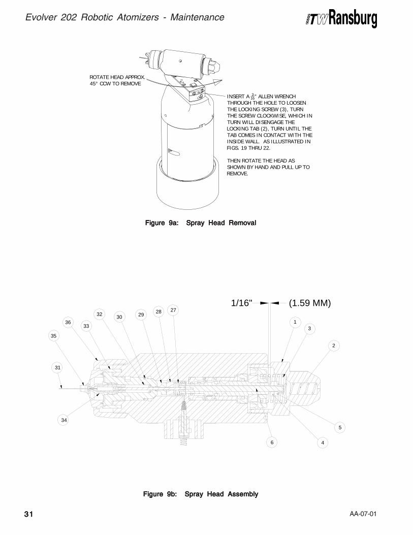
AA-07-013131313131
Evolver 202 Robotic Atomizers - Maintenance
Figure 9b: Spray Head AssemblyFigure 9b: Spray Head AssemblyFigure 9b: Spray Head AssemblyFigure 9b: Spray Head AssemblyFigure 9b: Spray Head Assembly
Figure 9a: Spray Head RemovalFigure 9a: Spray Head RemovalFigure 9a: Spray Head RemovalFigure 9a: Spray Head RemovalFigure 9a: Spray Head Removal
4
5
1/16" (1.59 MM)
34
31
35
29
3633
32 3028 27
6
2
31
ROTATE HEAD APPROX.45° CCW TO REMOVE
INSERT A 316" ALLEN WRENCH
THROUGH THE HOLE TO LOOSENTHE LOCKING SCREW (3), TURNTHE SCREW CLOCKWISE, WHICH INTURN WILL DISENGAGE THELOCKING TAB (2), TURN UNTIL THETAB COMES IN CONTACT WITH THEINSIDE WALL. AS ILLUSTRATED INFIGS. 19 THRU 22.
THEN ROTATE THE HEAD ASSHOWN BY HAND AND PULL UP TOREMOVE.
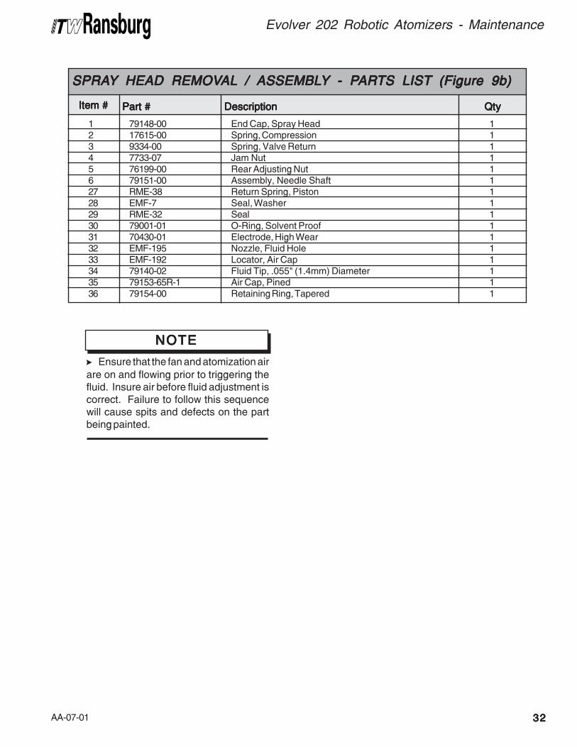
AA-07-01 3232323232
Evolver 202 Robotic Atomizers - Maintenance
Item #Item #Item #Item #Item #
SPRASPRASPRASPRASPRAYYYYY HEAD REMOV HEAD REMOV HEAD REMOV HEAD REMOV HEAD REMOVALALALALAL / / / / / ASSEMBLASSEMBLASSEMBLASSEMBLASSEMBLYYYYY - P- P- P- P- PARARARARARTS LISTTS LISTTS LISTTS LISTTS LIST (Figure 9b) (Figure 9b) (Figure 9b) (Figure 9b) (Figure 9b)
Part #Part #Part #Part #Part # DescriptionDescriptionDescriptionDescriptionDescription QtyQtyQtyQtyQty
1 79148-00 End Cap, Spray Head 12 17615-00 Spring, Compression 13 9334-00 Spring, Valve Return 14 7733-07 Jam Nut 15 76199-00 Rear Adjusting Nut 16 79151-00 Assembly, Needle Shaft 127 RME-38 Return Spring, Piston 128 EMF-7 Seal, Washer 129 RME-32 Seal 130 79001-01 O-Ring, Solvent Proof 131 70430-01 Electrode, High Wear 132 EMF-195 Nozzle, Fluid Hole 133 EMF-192 Locator, Air Cap 134 79140-02 Fluid Tip, .055" (1.4mm) Diameter 135 79153-65R-1 Air Cap, Pined 136 79154-00 Retaining Ring, Tapered 1
> Ensure that the fan and atomization air
are on and flowing prior to triggering thefluid. Insure air before fluid adjustment iscorrect. Failure to follow this sequencewill cause spits and defects on the partbeing painted.
NOTENOTENOTENOTENOTE
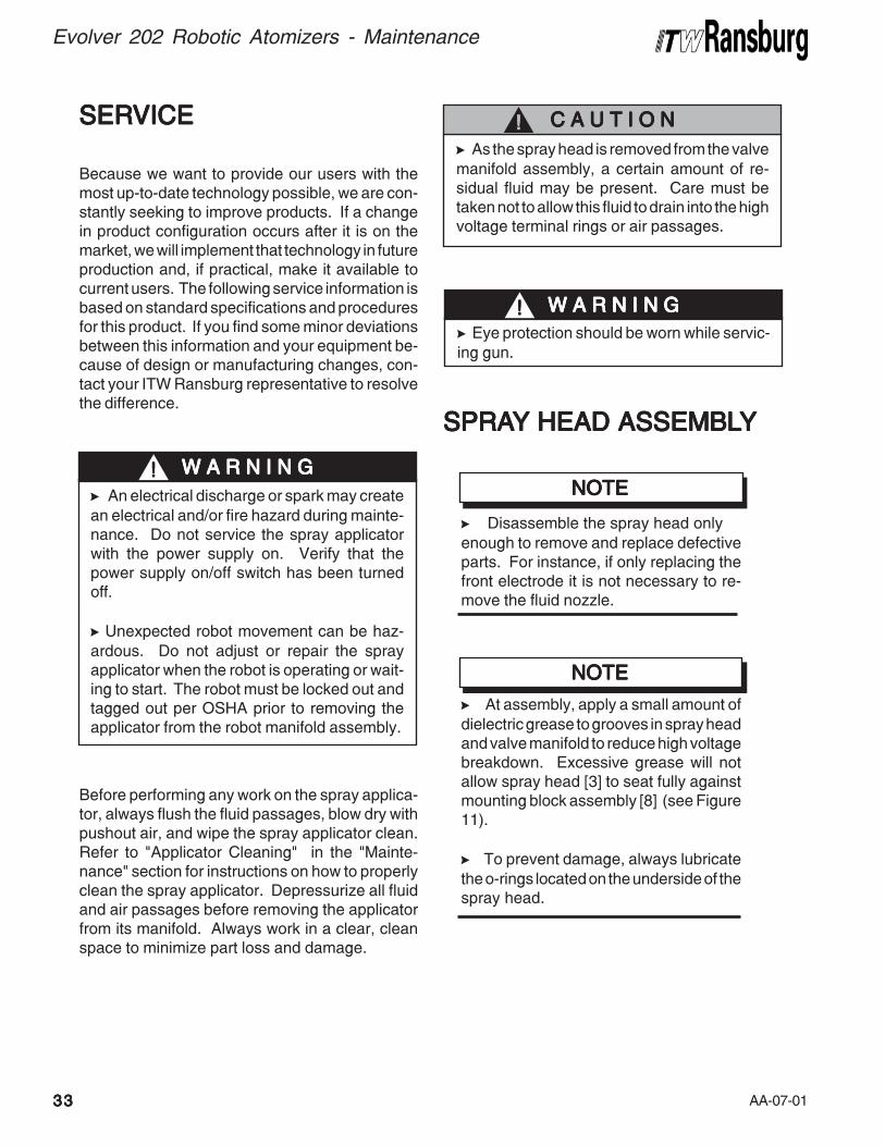
AA-07-013333333333
Evolver 202 Robotic Atomizers - Maintenance
SERSERSERSERSERVICEVICEVICEVICEVICE
Because we want to provide our users with themost up-to-date technology possible, we are con-stantly seeking to improve products. If a changein product configuration occurs after it is on themarket, we will implement that technology in futureproduction and, if practical, make it available tocurrent users. The following service information isbased on standard specifications and proceduresfor this product. If you find some minor deviationsbetween this information and your equipment be-cause of design or manufacturing changes, con-tact your ITW Ransburg representative to resolvethe difference.
> An electrical discharge or spark may create
an electrical and/or fire hazard during mainte-nance. Do not service the spray applicatorwith the power supply on. Verify that thepower supply on/off switch has been turnedoff.
> Unexpected robot movement can be haz-
ardous. Do not adjust or repair the sprayapplicator when the robot is operating or wait-ing to start. The robot must be locked out andtagged out per OSHA prior to removing theapplicator from the robot manifold assembly.
W A R N I N GW A R N I N GW A R N I N GW A R N I N GW A R N I N G!!!!!
Before performing any work on the spray applica-tor, always flush the fluid passages, blow dry withpushout air, and wipe the spray applicator clean.Refer to "Applicator Cleaning" in the "Mainte-nance" section for instructions on how to properlyclean the spray applicator. Depressurize all fluidand air passages before removing the applicatorfrom its manifold. Always work in a clear, cleanspace to minimize part loss and damage.
SPRASPRASPRASPRASPRAYYYYY HEAD ASSEMBL HEAD ASSEMBL HEAD ASSEMBL HEAD ASSEMBL HEAD ASSEMBLYYYYY
> As the spray head is removed from the valve
manifold assembly, a certain amount of re-sidual fluid may be present. Care must betaken not to allow this fluid to drain into the highvoltage terminal rings or air passages.
C A U T I O NC A U T I O NC A U T I O NC A U T I O NC A U T I O N!!!!!
> Disassemble the spray head only
enough to remove and replace defectiveparts. For instance, if only replacing thefront electrode it is not necessary to re-move the fluid nozzle.
NOTENOTENOTENOTENOTE
> At assembly, apply a small amount of
dielectric grease to grooves in spray headand valve manifold to reduce high voltagebreakdown. Excessive grease will notallow spray head [3] to seat fully againstmounting block assembly [8] (see Figure11).
> To prevent damage, always lubricate
the o-rings located on the underside of thespray head.
NOTENOTENOTENOTENOTE
> Eye protection should be worn while servic-
ing gun.
W A R N I N GW A R N I N GW A R N I N GW A R N I N GW A R N I N G!!!!!
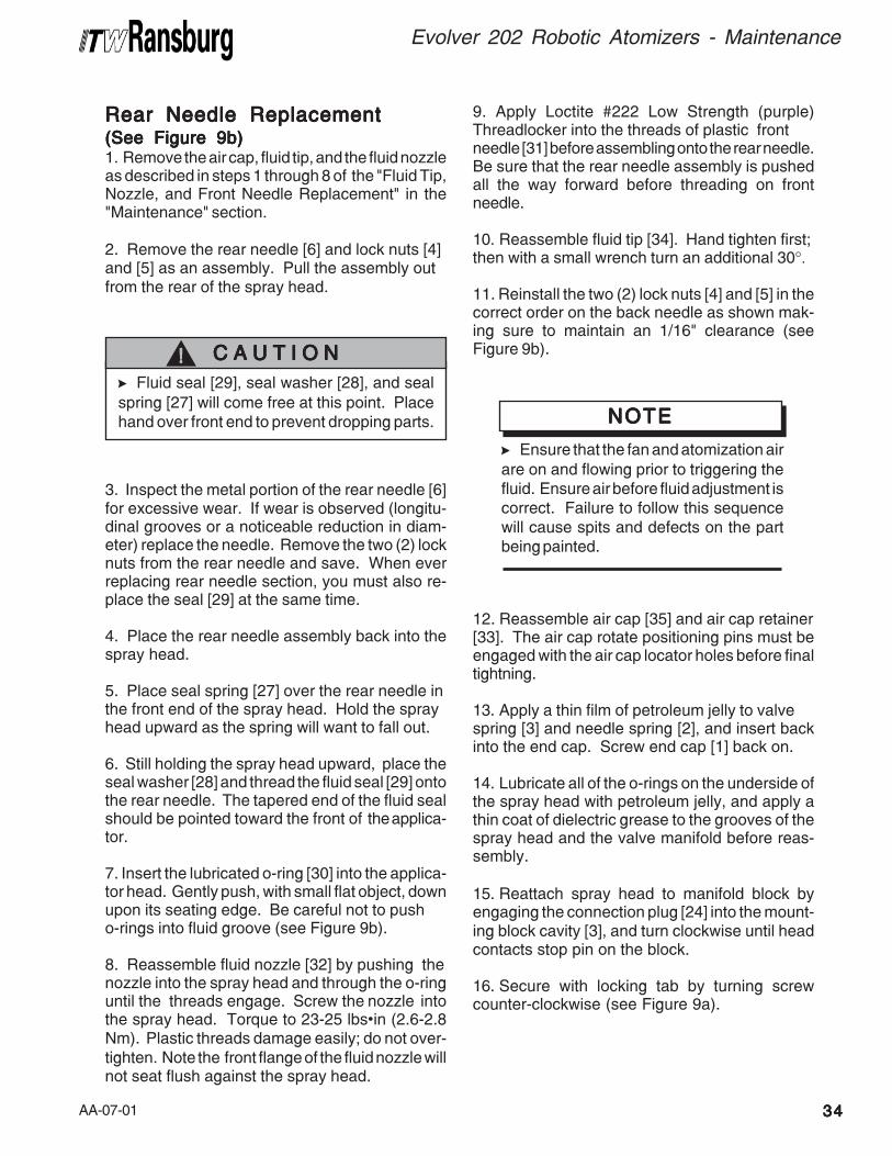
AA-07-01 3434343434
Evolver 202 Robotic Atomizers - Maintenance
Rear Needle ReplacementRear Needle ReplacementRear Needle ReplacementRear Needle ReplacementRear Needle Replacement(See Figure 9b)(See Figure 9b)(See Figure 9b)(See Figure 9b)(See Figure 9b)1. Remove the air cap, fluid tip, and the fluid nozzleas described in steps 1 through 8 of the "Fluid Tip,Nozzle, and Front Needle Replacement" in the"Maintenance" section.
2. Remove the rear needle [6] and lock nuts [4]and [5] as an assembly. Pull the assembly outfrom the rear of the spray head.
> Fluid seal [29], seal washer [28], and seal
spring [27] will come free at this point. Placehand over front end to prevent dropping parts.
C A U T I O NC A U T I O NC A U T I O NC A U T I O NC A U T I O N!!!!!
3. Inspect the metal portion of the rear needle [6]for excessive wear. If wear is observed (longitu-dinal grooves or a noticeable reduction in diam-eter) replace the needle. Remove the two (2) locknuts from the rear needle and save. When everreplacing rear needle section, you must also re-place the seal [29] at the same time.
4. Place the rear needle assembly back into thespray head.
5. Place seal spring [27] over the rear needle inthe front end of the spray head. Hold the sprayhead upward as the spring will want to fall out.
6. Still holding the spray head upward, place theseal washer [28] and thread the fluid seal [29] ontothe rear needle. The tapered end of the fluid sealshould be pointed toward the front of the applica-tor.
7. Insert the lubricated o-ring [30] into the applica-tor head. Gently push, with small flat object, downupon its seating edge. Be careful not to pusho-rings into fluid groove (see Figure 9b).
8. Reassemble fluid nozzle [32] by pushing thenozzle into the spray head and through the o-ringuntil the threads engage. Screw the nozzle intothe spray head. Torque to 23-25 lbs•in (2.6-2.8Nm). Plastic threads damage easily; do not over-tighten. Note the front flange of the fluid nozzle willnot seat flush against the spray head.
9. Apply Loctite #222 Low Strength (purple)Threadlocker into the threads of plastic frontneedle [31] before assembling onto the rear needle.Be sure that the rear needle assembly is pushedall the way forward before threading on frontneedle.
10. Reassemble fluid tip [34]. Hand tighten first;then with a small wrench turn an additional 30°.
11. Reinstall the two (2) lock nuts [4] and [5] in thecorrect order on the back needle as shown mak-ing sure to maintain an 1/16" clearance (seeFigure 9b).
> Ensure that the fan and atomization air
are on and flowing prior to triggering thefluid. Ensure air before fluid adjustment iscorrect. Failure to follow this sequencewill cause spits and defects on the partbeing painted.
NOTENOTENOTENOTENOTE
12. Reassemble air cap [35] and air cap retainer[33]. The air cap rotate positioning pins must beengaged with the air cap locator holes before finaltightning.
13. Apply a thin film of petroleum jelly to valvespring [3] and needle spring [2], and insert backinto the end cap. Screw end cap [1] back on.
14. Lubricate all of the o-rings on the underside ofthe spray head with petroleum jelly, and apply athin coat of dielectric grease to the grooves of thespray head and the valve manifold before reas-sembly.
15. Reattach spray head to manifold block byengaging the connection plug [24] into the mount-ing block cavity [3], and turn clockwise until headcontacts stop pin on the block.
16. Secure with locking tab by turning screwcounter-clockwise (see Figure 9a).
AA-07-013535353535
Evolver 202 Robotic Atomizers - Maintenance
Air VAir VAir VAir VAir Valve Removalalve Removalalve Removalalve Removalalve Removal(See Figure 10)(See Figure 10)(See Figure 10)(See Figure 10)(See Figure 10)1. After removal of end cap and spring, the airvalve can be pulled straight out the back of thehead assembly.
2. Inspect and replace the u-cup [8], if necessary,by holding the air valve shaft on it's flats andloosening the piston nut [7] counter-clockwise.
3. Remove the seal carrier with seal removal tool[B].
4. Use a bent hook to reach inside the air valvebushing [14], grip slot and pull out. Use the sameprocedure to pull out the rear seal carrier [17].
> Use Caution as NOT TONOT TONOT TONOT TONOT TO scratch or raise
burrs on inside diameters of the parts.
C A U T I O NC A U T I O NC A U T I O NC A U T I O NC A U T I O N!!!!!
12. If the locking tab plug connection [24] needsto be replaced, first remove the electrode springconnector [23] by pulling straight out with a needlenose pliers. If removed, the spring wire should bereplaced.
13. Remove socket head screw [22] and connec-tion plug [24] from body.
14. Replace conductive compressable contact[25] if necessary.
15. Reinstall the connection plug [24] into thebody, making sure the tabs on the bottom alignwith the notches in the body [19].
16. Insert and tighten the screw [22], making surethe tabs remain inside the notches [24] in the body.
17. Insert the spring electrode wire [23] throughthe hole in the screw using a needle nose pliers onthe straight wire portion. Carefully rotate andpush the wire through the screw hole and into thecompressable contact until the spring contactsthe screw head.
5. Remove and replace all o-rings if necessary.
6. O-rings [12] and [18] must be installed insidetheir mating parts (see Figure 10).
7. The Teflon o-ring [16] should be inserted intothe front of the bushing [14] and one of the o-rings[15] installed onto the outside groove before thebushing is installed.
8. Reassemble the remaining parts as shown inFigure 9 making sure that the alignment tab on thebushing [14] lines up with the align groove in thebody [19].
9. Torque the seal carriage [13] to 30-35 lbs•in(4.0-4.5 Nm).
10. If the u-cup needs to be replaced, assembleon piston plate [9] and push both onto shaft,tighten securely with piston nut [7] and install inbody as one assembly.
11. Assemble the remainder of the applicatorhead as stated earlier.

AA-07-01 3636363636
Evolver 202 Robotic Atomizers - Maintenance
NOTESNOTESNOTESNOTESNOTES
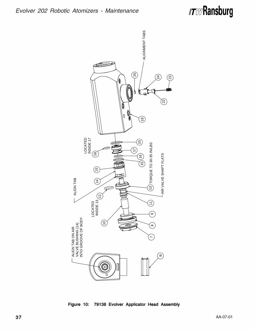
AA-07-01
Figure 10: 79138 Evolver Applicator Head AssemblyFigure 10: 79138 Evolver Applicator Head AssemblyFigure 10: 79138 Evolver Applicator Head AssemblyFigure 10: 79138 Evolver Applicator Head AssemblyFigure 10: 79138 Evolver Applicator Head Assembly
3737373737
Evolver 202 Robotic Atomizers - Maintenance
22
24
23
1113
25
17
15
1516
TO
RQ
UE
TO
30-
35 IN
/LB
S8
79
LO
CA
TE
D IN
SID
E 1
3
10
18L
OC
AT
ED
INS
IDE
17
15
1412
19
AIR
VA
LVE
SH
AF
T F
LAT
SB
ALI
GN
ME
NT
TA
BS
ALI
GN
TA
B O
N A
IRV
ALV
E B
US
HIN
G (
14)
INT
O G
RO
OV
E O
F B
OD
Y
ALI
GN
TA
B
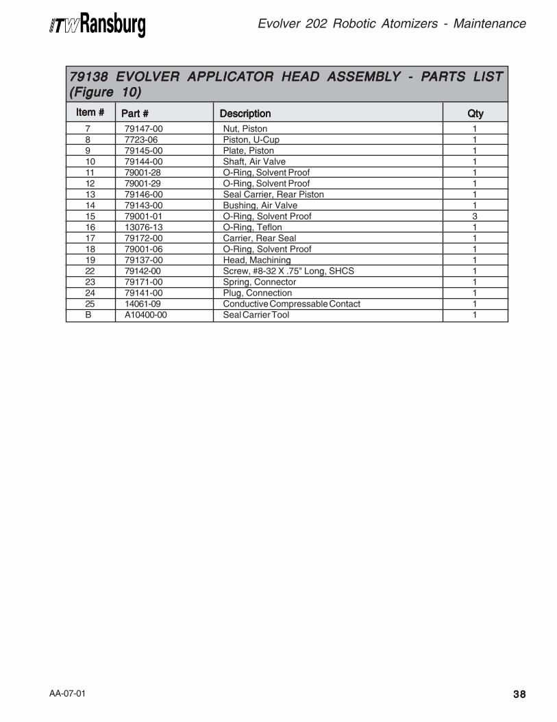
AA-07-01 3838383838
Evolver 202 Robotic Atomizers - Maintenance
7 79147-00 Nut, Piston 18 7723-06 Piston, U-Cup 19 79145-00 Plate, Piston 110 79144-00 Shaft, Air Valve 111 79001-28 O-Ring, Solvent Proof 112 79001-29 O-Ring, Solvent Proof 113 79146-00 Seal Carrier, Rear Piston 114 79143-00 Bushing, Air Valve 115 79001-01 O-Ring, Solvent Proof 316 13076-13 O-Ring, Teflon 117 79172-00 Carrier, Rear Seal 118 79001-06 O-Ring, Solvent Proof 119 79137-00 Head, Machining 122 79142-00 Screw, #8-32 X .75" Long, SHCS 123 79171-00 Spring, Connector 124 79141-00 Plug, Connection 125 14061-09 Conductive Compressable Contact 1B A10400-00 Seal Carrier Tool 1
Item #Item #Item #Item #Item #
79138 EVOL79138 EVOL79138 EVOL79138 EVOL79138 EVOLVER APPLICAVER APPLICAVER APPLICAVER APPLICAVER APPLICATTTTTOR HEAD ASSEMBLOR HEAD ASSEMBLOR HEAD ASSEMBLOR HEAD ASSEMBLOR HEAD ASSEMBLYYYYY - P - P - P - P - PARARARARARTS LISTTS LISTTS LISTTS LISTTS LIST(Figure 10)(Figure 10)(Figure 10)(Figure 10)(Figure 10)
Part #Part #Part #Part #Part # DescriptionDescriptionDescriptionDescriptionDescription QtyQtyQtyQtyQty
AA-07-01
REMOVING SPRAREMOVING SPRAREMOVING SPRAREMOVING SPRAREMOVING SPRAYYYYY
APPLICAAPPLICAAPPLICAAPPLICAAPPLICATTTTTOR FROM THEOR FROM THEOR FROM THEOR FROM THEOR FROM THE
REAR MANIFOLDREAR MANIFOLDREAR MANIFOLDREAR MANIFOLDREAR MANIFOLD
ASSEMBLASSEMBLASSEMBLASSEMBLASSEMBLYYYYY(See Figure 1(See Figure 1(See Figure 1(See Figure 1(See Figure 11)1)1)1)1)
Anytime service is required within the applicatorshroud, the applicator should be removed from therobot mounting plate assembly. After the applicatoris removed from the robot, always move to a clear,clean work area to remove the applicator shroudand begin servicing.
1. Purge all fluid from the system and blow linesdry with pushout air before the applicator isremoved.
2. All pressures must be removed, both air andfluid, before removing the applicator. Fluid pressurecan be removed by actuating the applicator triggerwith the fluid regulator open.
3. Turn off the power supply to the applicator.
4. Remove applicator from robot by turning theretaining ring counter-clockwise from the manifoldrobot mounting plate.
5. Remove spray head [3] (see Figure 11) aspreviously described in Figure 9a. (see Figure11).
SSSSSpray Applicator Disassemblypray Applicator Disassemblypray Applicator Disassemblypray Applicator Disassemblypray Applicator Disassembly
(S(S(S(S(See Figures 12, 13, and 14ee Figures 12, 13, and 14ee Figures 12, 13, and 14ee Figures 12, 13, and 14ee Figures 12, 13, and 14)))))6. Remove the four (4) screws [1] from mountingblock [10] and pull the block out of the uppermanifold [11] as shown in Figure 12.
7. Remove and inspect the o-rings [2, 8, and 9].Replace if necessary (see Figure 12).
8. Remove mounting ring cover [7] by pullingstraight up as shown in Figure 12.
9. Remove mounting ring [6] by pulling straight upas shown in Figure 12.
3939393939
Evolver 202 Robotic Atomizers - Maintenance
10. Loosen the two (2) screws [3] on the shroudhalves. Carefully pry the shroud halves [4 and 5]apart by placing a thin blade screw driver inbetween them.
11. Loosen one end of the coiled fluid tube [13] byremoving the nut [6] and ferrules [7 and 8] from thevalve manifold [5] (see Figure 13).
12. Loosen one end of the gray rigid tube [12] byremoving the nut [9] and ferreles [10 and 11] fromthe valve manifold [5].
13. Remove the six (6) screws [17] and the four(4) screws [14] from the bottom of the mountingplate [4] (see Figure 13). Inspect the four (4)o-rings [15] located within the screws [14] andreplace if necessary.
14. Carefully pull upward on the head manifoldblock [22] which will disengage from the bottomvalve assembly block [5]. Inspect o-rings [2] onthe ends of the connecting rods [1]. Replace ifnecessary (see Figure 13).
15. Remove the four (4) connecting rods [1] byunscrewing counter-clockwise. Remove andinspect the four (4) studs [3] and the o-rings [2] andreplace if necessary.
16. Remove and inspect the coiled fluid tube byremoving the tube nut [6] and ferrules [7 and 8]from the upper head manifold [22].
17. Release the cascade cable from the valvemanifold by loosening the set screw [23]. Pull thecable out of the mounting plate [4], and cascade[19] out of the upper head manifold [22].
18. Reassemble in reverse order making sure toalign the cascade wire plug timing mark with thetiming mark on the mounting plate [4] as shown inFigure 13. Tighten set screw [23].
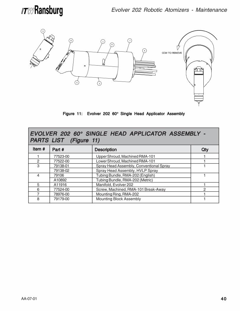
AA-07-01 4040404040
Evolver 202 Robotic Atomizers - Maintenance
Figure 11: Evolver 202 60Figure 11: Evolver 202 60Figure 11: Evolver 202 60Figure 11: Evolver 202 60Figure 11: Evolver 202 60° ° ° ° ° Single Head Single Head Single Head Single Head Single Head Applicator AssemblyApplicator AssemblyApplicator AssemblyApplicator AssemblyApplicator Assembly
3
5
6
1 7
4
2
8
CCW TO REMOVE
1 77523-00 Upper Shroud, Machined RMA-101 12 77522-00 Lower Shroud, Machined RMA-101 13 79138-01 Spray Head Assembly, Conventional Spray 1
79138-02 Spray Head Assembly, HVLP Spray4 79106 Tubing Bundle, RMA-202 (English) 1
A10892 Tubing Bundle, RMA-202 (Metric)5 A11916 Manifold, Evolver 202 16 77524-00 Screw, Machined, RMA-101 Break-Away 27 78976-00 Mounting Ring, RMA-202 18 79179-00 Mounting Block Assembly 1
Item #Item #Item #Item #Item #
EVOLEVOLEVOLEVOLEVOLVER 202 60VER 202 60VER 202 60VER 202 60VER 202 60°°°°° SINGLE HEAD APPLICA SINGLE HEAD APPLICA SINGLE HEAD APPLICA SINGLE HEAD APPLICA SINGLE HEAD APPLICATTTTTOR OR OR OR OR ASSEMBLASSEMBLASSEMBLASSEMBLASSEMBLYYYYY -----PPPPPARARARARARTS LISTTS LISTTS LISTTS LISTTS LIST (Figure 1 (Figure 1 (Figure 1 (Figure 1 (Figure 11)1)1)1)1)
Part #Part #Part #Part #Part # DescriptionDescriptionDescriptionDescriptionDescription QtyQtyQtyQtyQty
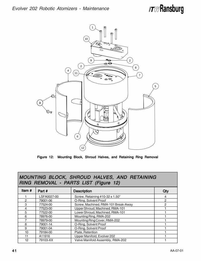
AA-07-014141414141
Evolver 202 Robotic Atomizers - Maintenance
Figure 12: Mounting Block, Shroud Halves, and Retaining Ring RemovalFigure 12: Mounting Block, Shroud Halves, and Retaining Ring RemovalFigure 12: Mounting Block, Shroud Halves, and Retaining Ring RemovalFigure 12: Mounting Block, Shroud Halves, and Retaining Ring RemovalFigure 12: Mounting Block, Shroud Halves, and Retaining Ring Removal
33
4
5
7
2 8
29
10
1
6
11
12
1 LSFA0027-00 Screw, Retaining #10-32 x 1.50" 42 79001-06 O-Ring, Solvent Proof 23 77524-00 Screw, Machined, RMA-101 Break-Away 24 77523-00 Upper Shroud, Machined, RMA-101 15 77522-00 Lower Shroud, Machined, RMA-101 16 78976-00 Mounting Ring, RMA-202 17 78979-00 Mounting Ring Cover, RMA-202 18 79001-14 O-Ring, Solvent Proof 19 79001-04 O-Ring, Solvent Proof 110 79184-00 Plate, Retention 111 A11916 Upper Manifold, Evolver 202 112 79103-XX Valve Manifold Assembly, RMA-202 1
Item #Item #Item #Item #Item #
MOUNTING BLOCK, SHROUD HALMOUNTING BLOCK, SHROUD HALMOUNTING BLOCK, SHROUD HALMOUNTING BLOCK, SHROUD HALMOUNTING BLOCK, SHROUD HALVES, AND RETVES, AND RETVES, AND RETVES, AND RETVES, AND RETAININGAININGAININGAININGAININGRING REMOVRING REMOVRING REMOVRING REMOVRING REMOVALALALALAL - P- P- P- P- PARARARARARTS LISTTS LISTTS LISTTS LISTTS LIST (Figure 12) (Figure 12) (Figure 12) (Figure 12) (Figure 12)
Part #Part #Part #Part #Part # DescriptionDescriptionDescriptionDescriptionDescription QtyQtyQtyQtyQty

AA-07-01 4242424242
Evolver 202 Robotic Atomizers - Maintenance
NOTESNOTESNOTESNOTESNOTES
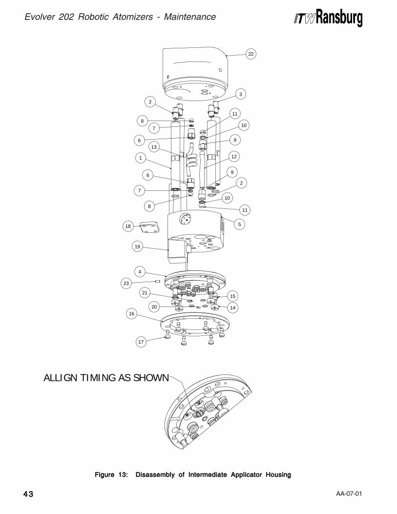
AA-07-014343434343
Evolver 202 Robotic Atomizers - Maintenance
Figure 13: Disassembly of Intermediate Applicator HousingFigure 13: Disassembly of Intermediate Applicator HousingFigure 13: Disassembly of Intermediate Applicator HousingFigure 13: Disassembly of Intermediate Applicator HousingFigure 13: Disassembly of Intermediate Applicator Housing
19
18
17
15
14
11
10
10
11
12
9
913
8
7
6
7
6
1
8
5
4
16
3
2
2
23
22
20
21
ALLIGN TIMING AS SHOWN
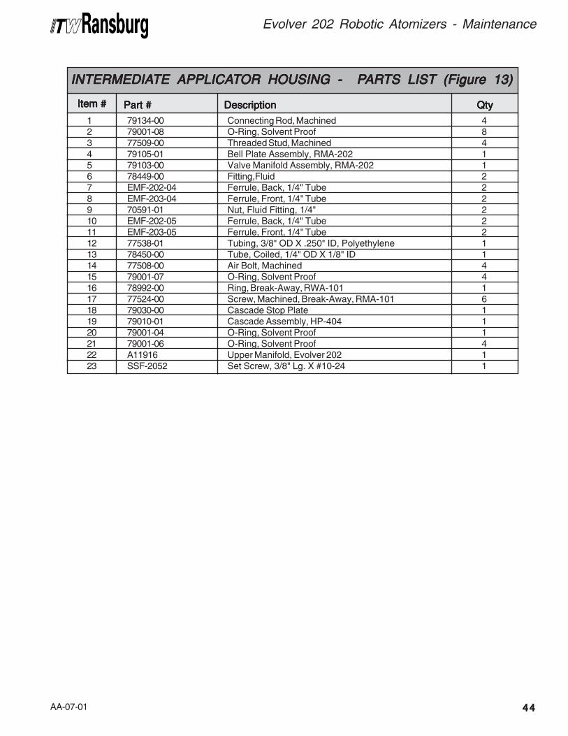
AA-07-01 4444444444
Evolver 202 Robotic Atomizers - Maintenance
1 79134-00 Connecting Rod, Machined 42 79001-08 O-Ring, Solvent Proof 83 77509-00 Threaded Stud, Machined 44 79105-01 Bell Plate Assembly, RMA-202 15 79103-00 Valve Manifold Assembly, RMA-202 16 78449-00 Fitting,Fluid 27 EMF-202-04 Ferrule, Back, 1/4" Tube 28 EMF-203-04 Ferrule, Front, 1/4" Tube 29 70591-01 Nut, Fluid Fitting, 1/4" 210 EMF-202-05 Ferrule, Back, 1/4" Tube 211 EMF-203-05 Ferrule, Front, 1/4" Tube 212 77538-01 Tubing, 3/8" OD X .250" ID, Polyethylene 113 78450-00 Tube, Coiled, 1/4" OD X 1/8" ID 114 77508-00 Air Bolt, Machined 415 79001-07 O-Ring, Solvent Proof 416 78992-00 Ring, Break-Away, RWA-101 117 77524-00 Screw, Machined, Break-Away, RMA-101 618 79030-00 Cascade Stop Plate 119 79010-01 Cascade Assembly, HP-404 120 79001-04 O-Ring, Solvent Proof 121 79001-06 O-Ring, Solvent Proof 422 A11916 Upper Manifold, Evolver 202 123 SSF-2052 Set Screw, 3/8" Lg. X #10-24 1
Item #Item #Item #Item #Item #
INTERMEDIAINTERMEDIAINTERMEDIAINTERMEDIAINTERMEDIATE APPLICATE APPLICATE APPLICATE APPLICATE APPLICATTTTTOR HOUSING - POR HOUSING - POR HOUSING - POR HOUSING - POR HOUSING - PARARARARARTS LISTTS LISTTS LISTTS LISTTS LIST (Figure 13) (Figure 13) (Figure 13) (Figure 13) (Figure 13)
Part #Part #Part #Part #Part # DescriptionDescriptionDescriptionDescriptionDescription QtyQtyQtyQtyQty
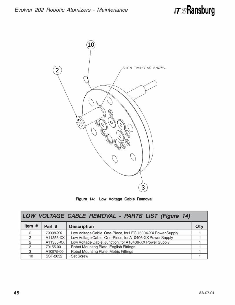
AA-07-014545454545
Evolver 202 Robotic Atomizers - Maintenance
Figure 14: Low Voltage Cable RemovalFigure 14: Low Voltage Cable RemovalFigure 14: Low Voltage Cable RemovalFigure 14: Low Voltage Cable RemovalFigure 14: Low Voltage Cable Removal
2 79008-XX Low Voltage Cable, One-Piece, for LECU5004-XX Power Supply 12 A11353-XX Low Voltage Cable, One-Piece, for A10406-XX Power Supply 12 A11355-XX Low Voltage Cable, Junction, for A10406-XX Power Supply 13 79155-00 Robot Mounting Plate, English Fittings 13 A10975-00 Robot Mounting Plate, Metric Fittings 110 SSF-2052 Set Screw 1
Item #Item #Item #Item #Item #
LOW VOLLOW VOLLOW VOLLOW VOLLOW VOLTTTTTAGE CABLE REMOVAGE CABLE REMOVAGE CABLE REMOVAGE CABLE REMOVAGE CABLE REMOVALALALALAL - P - P - P - P - PARARARARARTS LISTTS LISTTS LISTTS LISTTS LIST (Figure 14) (Figure 14) (Figure 14) (Figure 14) (Figure 14)
Part #Part #Part #Part #Part # DescriptionDescriptionDescriptionDescriptionDescription Q t yQ t yQ t yQ t yQ t y
3
2
10
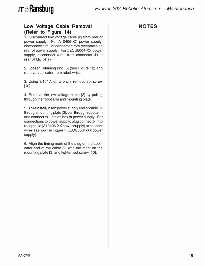
AA-07-01 4646464646
Evolver 202 Robotic Atomizers - Maintenance
Low VLow VLow VLow VLow Voltage Cable Removaloltage Cable Removaloltage Cable Removaloltage Cable Removaloltage Cable Removal
(Refer to Figure 14)(Refer to Figure 14)(Refer to Figure 14)(Refer to Figure 14)(Refer to Figure 14)1. Disconnect low voltage cable [2] from rear ofpower supply. For A10406-XX power supply,disconnect circular connector from receptacle onrear of power supply. For LECU5004-XX powersupply, disconnect wires from connector J3 atrear of MicroPak.
2. Loosen retaining ring [6] (see Figure 12) andremove applicator from robot wrist.
3. Using 3/16" Allen wrench, remove set screw[10].
4. Remove the low voltage cable [2] by pullingthrough the robot arm and mounting plate.
5. To reinstall, insert power supply end of cable [2]through mounting plate [3], pull through robot armand connect to junction box or power supply. Forconnections to power supply, plug connector intoreceptacle (A10406-XX power supply) or connectwires as shown in Figure 4 (LECU5004-XX powersupply).
6. Align the timing mark of the plug on the appli-cator end of the cable [2] with the mark on themounting plate [3] and tighten set screw [10].
NOTESNOTESNOTESNOTESNOTES
AA-07-014747474747
Evolver 202 Robotic Atomizers - Maintenance
13
2
1
4
3
2
Figure 15b: 79103-01 Single Purge Valve Manifold DisassemblyFigure 15b: 79103-01 Single Purge Valve Manifold DisassemblyFigure 15b: 79103-01 Single Purge Valve Manifold DisassemblyFigure 15b: 79103-01 Single Purge Valve Manifold DisassemblyFigure 15b: 79103-01 Single Purge Valve Manifold Disassembly
Figure 15a: 79103-00 Dual Purge Valve Manifold DisassemblyFigure 15a: 79103-00 Dual Purge Valve Manifold DisassemblyFigure 15a: 79103-00 Dual Purge Valve Manifold DisassemblyFigure 15a: 79103-00 Dual Purge Valve Manifold DisassemblyFigure 15a: 79103-00 Dual Purge Valve Manifold Disassembly
Install assemblies as shown. Apply A11545-00 Petroleum jelly to o-rings. Torque to 15-20 lbs•in (1.70-2.3 Nm) after valve is down.Install valve seat assemblies as shown. Apply A11545-00 Petroleum jelly to o-rings. Torque to 15-20lbs•in (1.70-2.3 Nm)
PPPPPARARARARARTS LISTTS LISTTS LISTTS LISTTS LIST BULLET BULLET BULLET BULLET BULLET DEFINITION T DEFINITION T DEFINITION T DEFINITION T DEFINITION TABLE - (Figures 15a and 15b)ABLE - (Figures 15a and 15b)ABLE - (Figures 15a and 15b)ABLE - (Figures 15a and 15b)ABLE - (Figures 15a and 15b)
1
2
1 79026-00 Valve Manifold 12 78949-00 Fluid Valve Assembly 53 77367-00 Valve Seat Assembly 5
Item #Item #Item #Item #Item #
79103-00 DUAL79103-00 DUAL79103-00 DUAL79103-00 DUAL79103-00 DUAL PURGE V PURGE V PURGE V PURGE V PURGE VALALALALALVE MANIFOLD - PVE MANIFOLD - PVE MANIFOLD - PVE MANIFOLD - PVE MANIFOLD - PARARARARARTS LISTTS LISTTS LISTTS LISTTS LIST(Figure 15a)(Figure 15a)(Figure 15a)(Figure 15a)(Figure 15a)
Part #Part #Part #Part #Part # DescriptionDescriptionDescriptionDescriptionDescription Q t yQ t yQ t yQ t yQ t y
1
2
1 79026-00 Valve Manifold 12 78949-00 Fluid Valve Assembly 33 77367-00 Valve Seat Assembly 34 77620-00 Kit, Valve Plug 2
Item #Item #Item #Item #Item #
79103-01 SINGLE PURGE V79103-01 SINGLE PURGE V79103-01 SINGLE PURGE V79103-01 SINGLE PURGE V79103-01 SINGLE PURGE VALALALALALVE MANIFOLD - PVE MANIFOLD - PVE MANIFOLD - PVE MANIFOLD - PVE MANIFOLD - PARARARARARTS LISTTS LISTTS LISTTS LISTTS LIST(Figure 15b)(Figure 15b)(Figure 15b)(Figure 15b)(Figure 15b)
Part #Part #Part #Part #Part # DescriptionDescriptionDescriptionDescriptionDescription Q t yQ t yQ t yQ t yQ t y
1
2
AA-07-01 4848484848
Evolver 202 Robotic Atomizers - Maintenance
REGULAREGULAREGULAREGULAREGULATTTTTOR VALOR VALOR VALOR VALOR VALVEVEVEVEVE
MANIFOLD ASSEMBLMANIFOLD ASSEMBLMANIFOLD ASSEMBLMANIFOLD ASSEMBLMANIFOLD ASSEMBLYYYYY(Figure 16)(Figure 16)(Figure 16)(Figure 16)(Figure 16)
Regulator Removal / ReplacementRegulator Removal / ReplacementRegulator Removal / ReplacementRegulator Removal / ReplacementRegulator Removal / ReplacementPrior to removing the regulator and related partsfrom the manifold, flush the system with solventand purge with air.
Using tool A10676-00, remove the regulator cap.Remove the six (6) stainless steel screws with aflat head screwdriver. Carefully remove theregulator bonnet. Then remove the diaphragmassembly. Next, remove the needle and seatassembly using a 3/16" Hex key.
Clean entire regulator with solvent and blow dry.Do not use any metal object to remove dried paintfrom any surface. Damage to the diaphragmsealing surface and the needle seat assembly willresult in leaks and may permanently damagevalve manifold. If regulator was disassembledbecause of leakage (fluid downstream of regula-tor), discard entire needle, seat, o-ring, and springand replace with new.
Regulator DiaphragmRegulator DiaphragmRegulator DiaphragmRegulator DiaphragmRegulator DiaphragmRemove the screw holding the upper plate andlower plate of the assembly with a Phillipsscrewdriver. Pull parts apart and discard thediaphragm. Inspect the lower plate for any damage,replace if necessary. Replace the o-ring that wasbetween the lower plate and the diaphragm.
Diaphragm AssemblyDiaphragm AssemblyDiaphragm AssemblyDiaphragm AssemblyDiaphragm AssemblyCarefully place the o-ring on the lower plate,center a new diaphragm over the parts, and centerthe upper plate over these parts. Install the screwwith a small amount of Loctite (7969-05) on thethreads. Tighten together to a torque of 8-10 lbs•in(.90-1.13 Nm). Make sure that Teflon (white sideof the diaphragm) faces towards the lower plate.
Seat Assembly ReplacementSeat Assembly ReplacementSeat Assembly ReplacementSeat Assembly ReplacementSeat Assembly ReplacementInstall the spring into the center-most cavity of themanifold. Place the pointed end of the needle ontothe center of the spring. Install the o-ring into thecavity of the seat. Lightly lubricate the o-ring withA11545-00 Petroleum jelly. Secure the needle/seat assembly by screwing the seat retainer intothe regulator cavity until a torque of 8-10 lbs•in(.90-1.13 Nm) is obtained. Use a 3/16" Hex keydriver.
Replacing Diaphragm AssemblyReplacing Diaphragm AssemblyReplacing Diaphragm AssemblyReplacing Diaphragm AssemblyReplacing Diaphragm AssemblyInstall assembly with the black rubber face towardsthe outside and align with the screw holes in thecavity. Place the regulator bonnet over thediaphragm assembly and align with screw holes ofthe diaphragm assembly and cavity. Insert all six(6) stainless steel scews and tighten in analternating 180° method. Install regulator cap andtighten to 125-135 lbs•in (14.1-15.3 Nm).
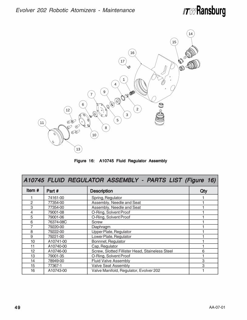
AA-07-014949494949
Evolver 202 Robotic Atomizers - Maintenance
Figure 16: A10745 Fluid Regulator AssemblyFigure 16: A10745 Fluid Regulator AssemblyFigure 16: A10745 Fluid Regulator AssemblyFigure 16: A10745 Fluid Regulator AssemblyFigure 16: A10745 Fluid Regulator Assembly
1 74161-00 Spring, Regulator 12 77354-00 Assembly, Needle and Seat 13 77354-00 Assembly, Needle and Seat 14 79001-08 O-Ring, Solvent Proof 15 79001-06 O-Ring, Solvent Proof 16 76374-08C Screw 17 79220-00 Diaphragm 18 79222-00 Upper Plate, Regulator 19 79221-00 Lower Plate, Regulator 110 A10741-00 Bonnnet, Regulator 111 A10740-00 Cap, Regulator 112 A10746-00 Screw, Slotted Fillister Head, Staineless Steel 613 79001-35 O-Ring, Solvent Proof 114 78949-00 Fluid Valve Assembly 315 77367-1 Valve Seat Assembly 316 A10743-00 Valve Manifold, Regulator, Evolver 202 1
Item #Item #Item #Item #Item #
A10745 FLUID REGULAA10745 FLUID REGULAA10745 FLUID REGULAA10745 FLUID REGULAA10745 FLUID REGULATTTTTOR ASSEMBLOR ASSEMBLOR ASSEMBLOR ASSEMBLOR ASSEMBLYYYYY - P - P - P - P - PARARARARARTS LISTTS LISTTS LISTTS LISTTS LIST (Figure 16) (Figure 16) (Figure 16) (Figure 16) (Figure 16)
Part #Part #Part #Part #Part # DescriptionDescriptionDescriptionDescriptionDescription QtyQtyQtyQtyQty
16
17
14
15
1
2
4
3
9
5
7
8
6
10
12
13
11
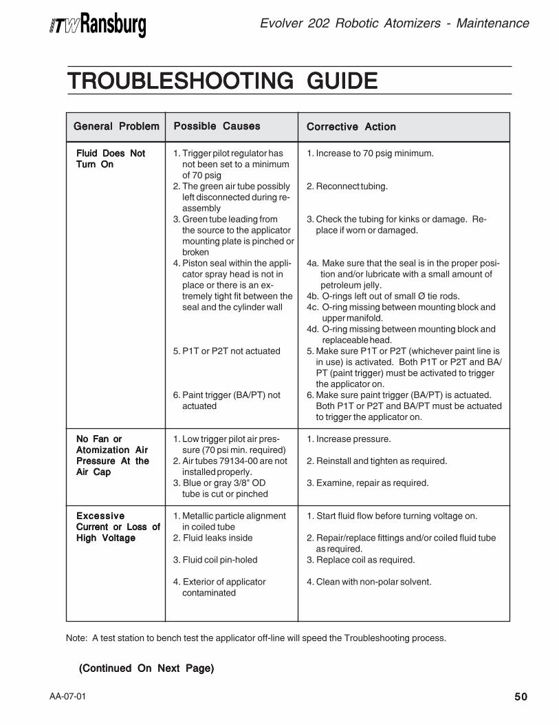
AA-07-01 5050505050
Evolver 202 Robotic Atomizers - Maintenance
TROUBLESHOOTING GUIDETROUBLESHOOTING GUIDETROUBLESHOOTING GUIDETROUBLESHOOTING GUIDETROUBLESHOOTING GUIDE
Note: A test station to bench test the applicator off-line will speed the Troubleshooting process.
General ProblemGeneral ProblemGeneral ProblemGeneral ProblemGeneral Problem Possible CausesPossible CausesPossible CausesPossible CausesPossible Causes Corrective ActionCorrective ActionCorrective ActionCorrective ActionCorrective Action
Fluid Does NotFluid Does NotFluid Does NotFluid Does NotFluid Does Not
Turn OnTurn OnTurn OnTurn OnTurn On
No Fan orNo Fan orNo Fan orNo Fan orNo Fan or
Atomization AirAtomization AirAtomization AirAtomization AirAtomization Air
Pressure At thePressure At thePressure At thePressure At thePressure At the
Air CapAir CapAir CapAir CapAir Cap
ExcessiveExcessiveExcessiveExcessiveExcessive
Current or Loss ofCurrent or Loss ofCurrent or Loss ofCurrent or Loss ofCurrent or Loss of
High VoltageHigh VoltageHigh VoltageHigh VoltageHigh Voltage
1. Trigger pilot regulator hasnot been set to a minimumof 70 psig
2. The green air tube possiblyleft disconnected during re-assembly
3. Green tube leading fromthe source to the applicatormounting plate is pinched orbroken
4. Piston seal within the appli-cator spray head is not inplace or there is an ex-tremely tight fit between theseal and the cylinder wall
5. P1T or P2T not actuated
6. Paint trigger (BA/PT) notactuated
1. Low trigger pilot air pres-sure (70 psi min. required)
2. Air tubes 79134-00 are notinstalled properly.
3. Blue or gray 3/8" ODtube is cut or pinched
1. Metallic particle alignmentin coiled tube
2. Fluid leaks inside
3. Fluid coil pin-holed
4. Exterior of applicatorcontaminated
1. Increase to 70 psig minimum.
2. Reconnect tubing.
3. Check the tubing for kinks or damage. Re-place if worn or damaged.
4a. Make sure that the seal is in the proper posi- tion and/or lubricate with a small amount of petroleum jelly.
4b. O-rings left out of small Ø tie rods.4c. O-ring missing between mounting block and
upper manifold.4d. O-ring missing between mounting block and
replaceable head.5. Make sure P1T or P2T (whichever paint line is
in use) is activated. Both P1T or P2T and BA/PT (paint trigger) must be activated to triggerthe applicator on.
6. Make sure paint trigger (BA/PT) is actuated.Both P1T or P2T and BA/PT must be actuatedto trigger the applicator on.
1. Increase pressure.
2. Reinstall and tighten as required.
3. Examine, repair as required.
1. Start fluid flow before turning voltage on.
2. Repair/replace fittings and/or coiled fluid tubeas required.
3. Replace coil as required.
4. Clean with non-polar solvent.
(Continued On Next Page)(Continued On Next Page)(Continued On Next Page)(Continued On Next Page)(Continued On Next Page)
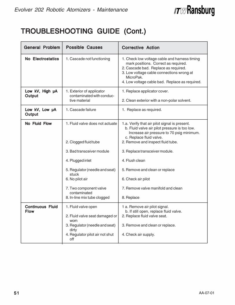
AA-07-015151515151
Evolver 202 Robotic Atomizers - Maintenance
TROUBLESHOOTING GUIDE (Cont.)TROUBLESHOOTING GUIDE (Cont.)TROUBLESHOOTING GUIDE (Cont.)TROUBLESHOOTING GUIDE (Cont.)TROUBLESHOOTING GUIDE (Cont.)
General ProblemGeneral ProblemGeneral ProblemGeneral ProblemGeneral Problem Possible CausesPossible CausesPossible CausesPossible CausesPossible Causes Corrective ActionCorrective ActionCorrective ActionCorrective ActionCorrective Action
No ElectrostaticsNo ElectrostaticsNo ElectrostaticsNo ElectrostaticsNo Electrostatics
Low kV, High μALow kV, High μALow kV, High μALow kV, High μALow kV, High μA
OutputOutputOutputOutputOutput
Low kV, Low μALow kV, Low μALow kV, Low μALow kV, Low μALow kV, Low μA
OutputOutputOutputOutputOutput
No Fluid FlowNo Fluid FlowNo Fluid FlowNo Fluid FlowNo Fluid Flow
Continuous FluidContinuous FluidContinuous FluidContinuous FluidContinuous Fluid
FlowFlowFlowFlowFlow
1. Cascade not functioning
1. Exterior of applicatorcontaminated with conduc-tive material
1. Cascade failure
1. Fluid valve does not actuate
2. Clogged fluid tube
3. Bad transceiver module
4. Plugged inlet
5. Regulator (needle and seat)stuck
6. No pilot air
7. Two component valvecontaminated
8. In-line mix tube clogged
1. Fluid valve open
2. Fluid valve seat damaged orworn
3. Regulator (needle and seat)dirty
4. Regulator pilot air not shutoff
1. Check low voltage cable and harness timingmark positions. Correct as required.
2. Cascade bad. Replace as required.3. Low voltage cable connections wrong at
MicroPak.4. Low voltage cable bad. Replace as required.
1. Replace applicator cover.
2. Clean exterior with a non-polar solvent.
1. Replace as required.
1.a. Verify that air pilot signal is present. b. Fluid valve air pilot pressure is too low.
Increase air pressure to 70 psig minimum. c. Replace fluid valve.2. Remove and inspect fluid tube.
3. Replace transceiver module.
4. Flush clean
5. Remove and clean or replace
6. Check air pilot
7. Remove valve manifold and clean
8. Replace
1 a. Remove air pilot signal. b. If still open, replace fluid valve.2. Replace fluid valve seat.
3. Remove and clean or replace.
4. Check air supply.
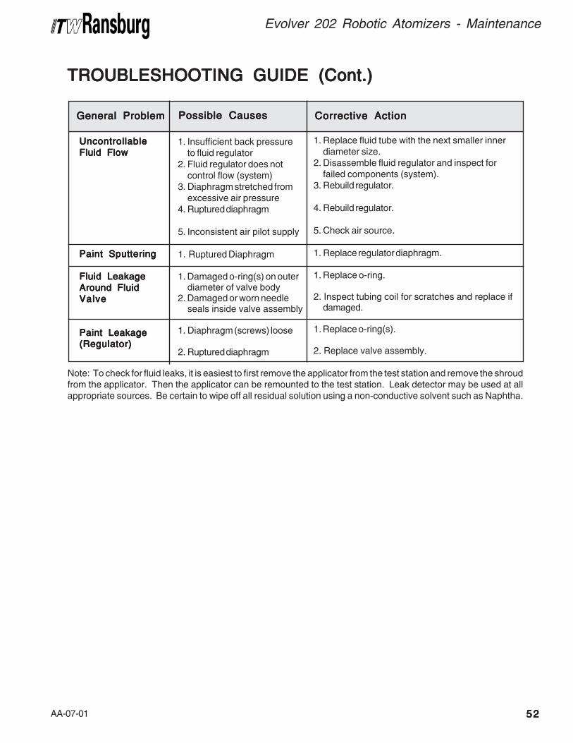
AA-07-01 5252525252
Evolver 202 Robotic Atomizers - Maintenance
Note: To check for fluid leaks, it is easiest to first remove the applicator from the test station and remove the shroudfrom the applicator. Then the applicator can be remounted to the test station. Leak detector may be used at allappropriate sources. Be certain to wipe off all residual solution using a non-conductive solvent such as Naphtha.
General ProblemGeneral ProblemGeneral ProblemGeneral ProblemGeneral Problem Possible CausesPossible CausesPossible CausesPossible CausesPossible Causes Corrective ActionCorrective ActionCorrective ActionCorrective ActionCorrective Action
1. Insufficient back pressureto fluid regulator
2. Fluid regulator does notcontrol flow (system)
3. Diaphragm stretched fromexcessive air pressure
4. Ruptured diaphragm
5. Inconsistent air pilot supply
1. Ruptured Diaphragm
1. Damaged o-ring(s) on outerdiameter of valve body
2. Damaged or worn needleseals inside valve assembly
1. Diaphragm (screws) loose
2. Ruptured diaphragm
1. Replace fluid tube with the next smaller innerdiameter size.
2. Disassemble fluid regulator and inspect forfailed components (system).
3. Rebuild regulator.
4. Rebuild regulator.
5. Check air source.
1. Replace regulator diaphragm.
1. Replace o-ring.
2. Inspect tubing coil for scratches and replace ifdamaged.
1. Replace o-ring(s).
2. Replace valve assembly.
UncontrollableUncontrollableUncontrollableUncontrollableUncontrollable
Fluid FlowFluid FlowFluid FlowFluid FlowFluid Flow
Paint SputteringPaint SputteringPaint SputteringPaint SputteringPaint Sputtering
Fluid LeakageFluid LeakageFluid LeakageFluid LeakageFluid Leakage
Around FluidAround FluidAround FluidAround FluidAround Fluid
ValveValveValveValveValve
Paint LeakagePaint LeakagePaint LeakagePaint LeakagePaint Leakage
(Regulator)(Regulator)(Regulator)(Regulator)(Regulator)
TROUBLESHOOTING GUIDE (Cont.)TROUBLESHOOTING GUIDE (Cont.)TROUBLESHOOTING GUIDE (Cont.)TROUBLESHOOTING GUIDE (Cont.)TROUBLESHOOTING GUIDE (Cont.)
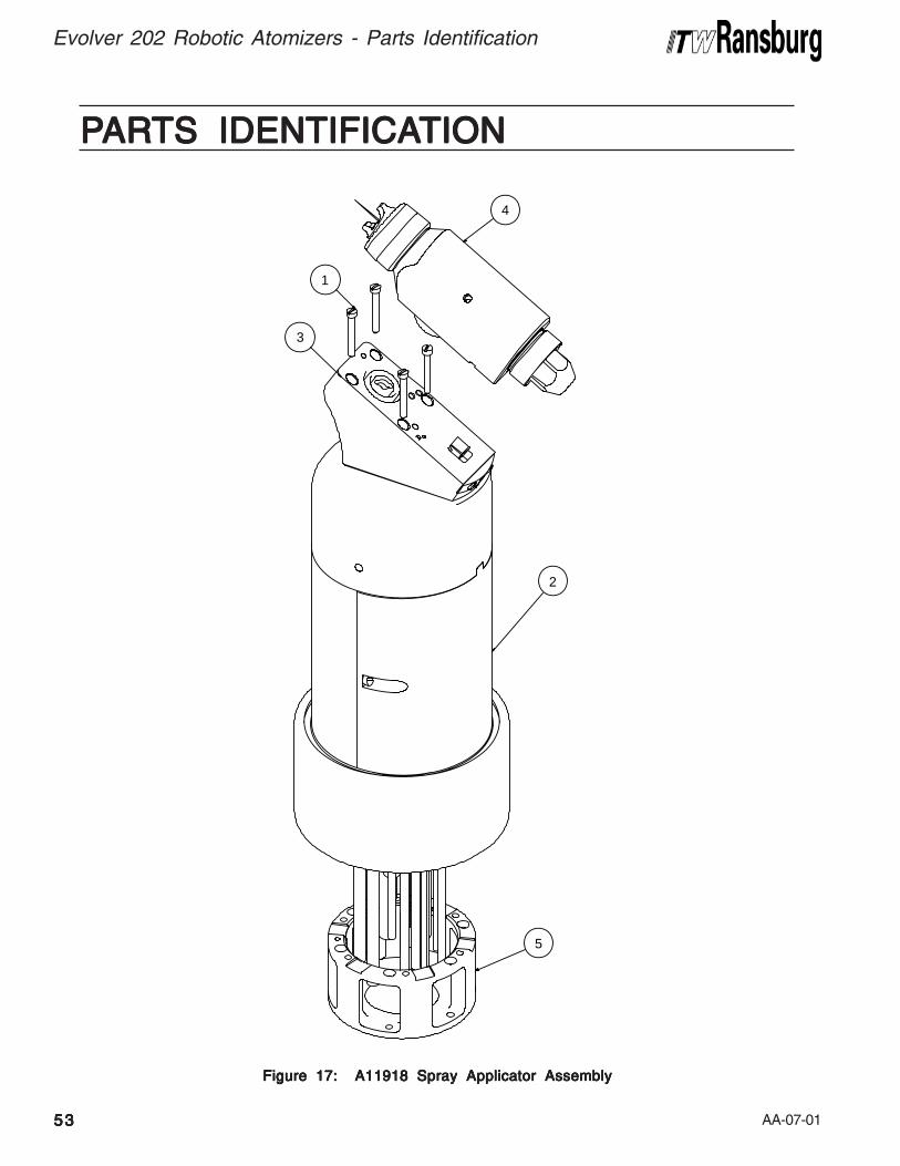
AA-07-015353535353
Evolver 202 Robotic Atomizers - Parts Identification
Figure 17: A11918 Spray Applicator AssemblyFigure 17: A11918 Spray Applicator AssemblyFigure 17: A11918 Spray Applicator AssemblyFigure 17: A11918 Spray Applicator AssemblyFigure 17: A11918 Spray Applicator Assembly
PPPPPARARARARARTS IDENTIFICATS IDENTIFICATS IDENTIFICATS IDENTIFICATS IDENTIFICATIONTIONTIONTIONTION
4
1
3
2
5

AA-07-01 5454545454
Evolver 202 Robotic Atomizers - Parts Identification
1 Table A - "A"Table A - "A"Table A - "A"Table A - "A"Table A - "A" Screw, #10-32, Thread 42 Table B - "B"Table B - "B"Table B - "B"Table B - "B"Table B - "B" Manifold Assembly 13 Table A - "C"Table A - "C"Table A - "C"Table A - "C"Table A - "C" Assembly, Mounting Block 14 Table C - "E"Table C - "E"Table C - "E"Table C - "E"Table C - "E" Assembly, Head Robot Gun Table A - "D"Table A - "D"Table A - "D"Table A - "D"Table A - "D"5 Table D - "F"Table D - "F"Table D - "F"Table D - "F"Table D - "F" Robot Adapters 1
Item #Item #Item #Item #Item #
A1A1A1A1A11918 SPRA1918 SPRA1918 SPRA1918 SPRA1918 SPRAYYYYY APPLICA APPLICA APPLICA APPLICA APPLICATTTTTOR ASSEMBLOR ASSEMBLOR ASSEMBLOR ASSEMBLOR ASSEMBLYYYYY - P - P - P - P - PARARARARARTS LISTTS LISTTS LISTTS LISTTS LIST(Figure 17)(Figure 17)(Figure 17)(Figure 17)(Figure 17)
Part #Part #Part #Part #Part # DescriptionDescriptionDescriptionDescriptionDescription Q t yQ t yQ t yQ t yQ t y
TTTTTABLE AABLE AABLE AABLE AABLE AHEAD CONFIGURAHEAD CONFIGURAHEAD CONFIGURAHEAD CONFIGURAHEAD CONFIGURATIONTIONTIONTIONTION
0123
DashDashDashDashDashNo.No.No.No.No. DescriptionDescriptionDescriptionDescriptionDescription
60° Single Head90° Single Head60° Dual Head90° Dual Head
"A""A""A""A""A"LSFA0027-00LSFA-0027-00
79206-0079206-00
"C""C""C""C""C"
79179-0079180-0079234-0079224-00
"D""D""D""D""D"
1122
TTTTTABLE BABLE BABLE BABLE BABLE BMANIFOLD CONFIGURAMANIFOLD CONFIGURAMANIFOLD CONFIGURAMANIFOLD CONFIGURAMANIFOLD CONFIGURATIONTIONTIONTIONTION
0123456
DashDashDashDashDashNo.No.No.No.No. DescriptionDescriptionDescriptionDescriptionDescription
Single Purge, No Regulator, for Highly Conductive Materials (Base/Clear)Dual Purge , No Regulator, for Highly Conductive Materials (Base/Clear)Single Purge W/RegulatorSingle Purge, No Regulator, for Conductive Materials (Base/Clear)Dual Purge, No Regulator, for Conductive Materials (Base/Clear)Single Purge, No Regulator, for Highly Resistive Materials (Clear Coat)Dual Purge, No Regulator, for Highly Resistive Materials (Clear Coat)
"B""B""B""B""B"A11917-01A11917-02A11917-03A11917-04A11917-05A11917-06A11917-07
TTTTTABLE CABLE CABLE CABLE CABLE CAAAAATTTTTOMIZAOMIZAOMIZAOMIZAOMIZATION TECHNOLOGYTION TECHNOLOGYTION TECHNOLOGYTION TECHNOLOGYTION TECHNOLOGY
01
DashDashDashDashDashNo.No.No.No.No. DescriptionDescriptionDescriptionDescriptionDescription
Conventional SprayHVLP Spray
"E""E""E""E""E"79138-0179138-02
TTTTTABLE DABLE DABLE DABLE DABLE DROBOT ADAPTERSROBOT ADAPTERSROBOT ADAPTERSROBOT ADAPTERSROBOT ADAPTERS
01234567
DashDashDashDashDashNo.No.No.No.No. DescriptionDescriptionDescriptionDescriptionDescription
No Adapter"ABB" Robot Adapter"Fanuc" P-155 Robot Adapter"Fanuc" P-200 Robot AdapterAdapter (Kawasaki-KE610L)Adapter (Motoman-PX2850)Adapter (Motoman-PX2900)Adapter (B & M-LZ2000)
"F""F""F""F""F"----
79107-0078983-0079131-00
A10847-00A10848-00A10849-00A10851-00
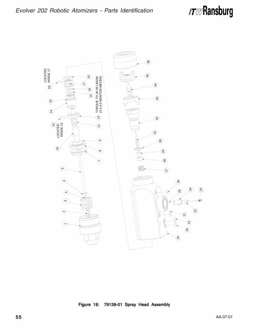
AA-07-015555555555
Evolver 202 Robotic Atomizers - Parts Identification
Figure 18: 79138-01 Spray Head AssemblyFigure 18: 79138-01 Spray Head AssemblyFigure 18: 79138-01 Spray Head AssemblyFigure 18: 79138-01 Spray Head AssemblyFigure 18: 79138-01 Spray Head Assembly
22
2120
21
2324
26
29
3132
3334
3536
9
10
12
78
53
46
12
TO
RQ
UE
TO
30-
35 L
BS
/IN(3
.4-4
.0 N
EW
TO
N M
ET
ER
)13
11
1615
15
17
LOC
AT
ED
IN
SID
E 1
3
141
5
LO
CA
TE
D
INS
IDE
17
18
2827
30
1925
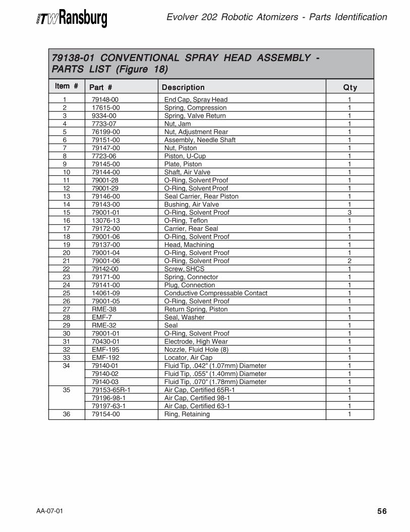
AA-07-01 5656565656
Evolver 202 Robotic Atomizers - Parts Identification
1 79148-00 End Cap, Spray Head 12 17615-00 Spring, Compression 13 9334-00 Spring, Valve Return 14 7733-07 Nut, Jam 15 76199-00 Nut, Adjustment Rear 16 79151-00 Assembly, Needle Shaft 17 79147-00 Nut, Piston 18 7723-06 Piston, U-Cup 19 79145-00 Plate, Piston 110 79144-00 Shaft, Air Valve 111 79001-28 O-Ring, Solvent Proof 112 79001-29 O-Ring, Solvent Proof 113 79146-00 Seal Carrier, Rear Piston 114 79143-00 Bushing, Air Valve 115 79001-01 O-Ring, Solvent Proof 316 13076-13 O-Ring, Teflon 117 79172-00 Carrier, Rear Seal 118 79001-06 O-Ring, Solvent Proof 119 79137-00 Head, Machining 120 79001-04 O-Ring, Solvent Proof 121 79001-06 O-Ring, Solvent Proof 222 79142-00 Screw, SHCS 123 79171-00 Spring, Connector 124 79141-00 Plug, Connection 125 14061-09 Conductive Compressable Contact 126 79001-05 O-Ring, Solvent Proof 127 RME-38 Return Spring, Piston 128 EMF-7 Seal, Washer 129 RME-32 Seal 130 79001-01 O-Ring, Solvent Proof 131 70430-01 Electrode, High Wear 132 EMF-195 Nozzle, Fluid Hole (8) 133 EMF-192 Locator, Air Cap 134 79140-01 Fluid Tip, .042" (1.07mm) Diameter 1
79140-02 Fluid Tip, .055" (1.40mm) Diameter 179140-03 Fluid Tip, .070" (1.78mm) Diameter 1
35 79153-65R-1 Air Cap, Certified 65R-1 179196-98-1 Air Cap, Certified 98-1 179197-63-1 Air Cap, Certified 63-1 1
36 79154-00 Ring, Retaining 1
Item #Item #Item #Item #Item #
79138-01 CONVENTIONAL79138-01 CONVENTIONAL79138-01 CONVENTIONAL79138-01 CONVENTIONAL79138-01 CONVENTIONAL SPRASPRASPRASPRASPRAYYYYY HEAD ASSEMBL HEAD ASSEMBL HEAD ASSEMBL HEAD ASSEMBL HEAD ASSEMBLYYYYY -----PPPPPARARARARARTS LISTTS LISTTS LISTTS LISTTS LIST (Figure 18) (Figure 18) (Figure 18) (Figure 18) (Figure 18)
Part #Part #Part #Part #Part # DescriptionDescriptionDescriptionDescriptionDescription Q t yQ t yQ t yQ t yQ t y
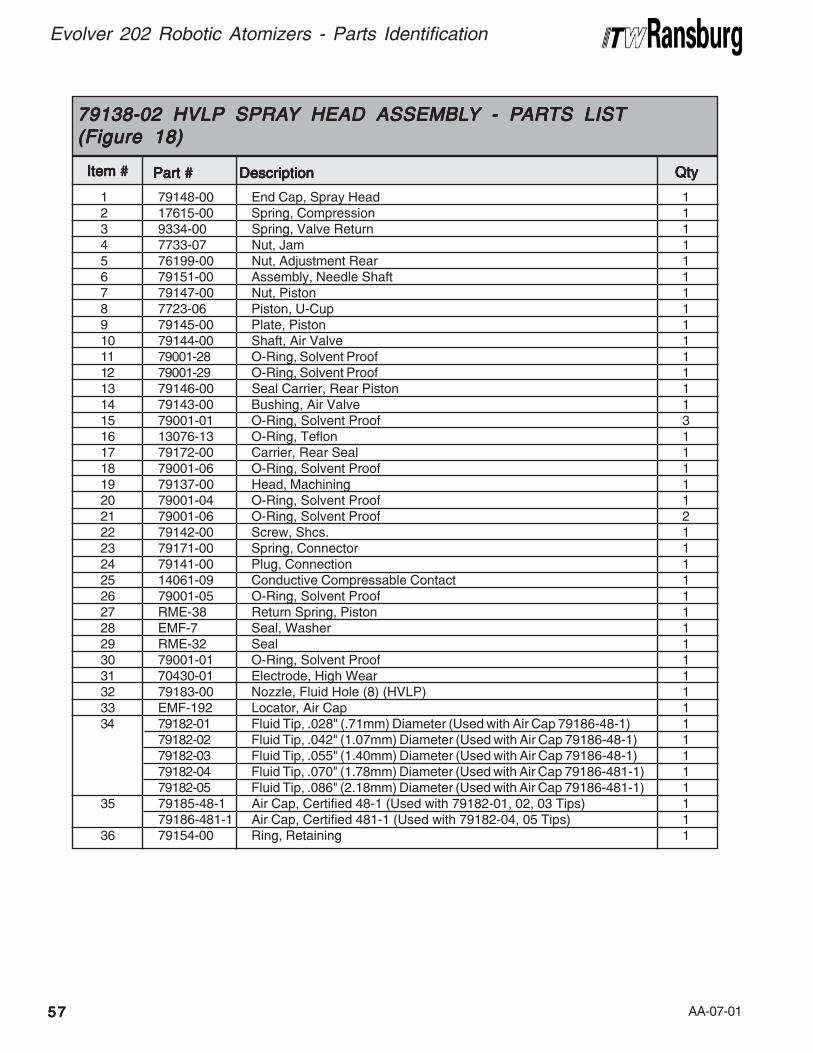
AA-07-01
Evolver 202 Robotic Atomizers - Parts Identification
5757575757
1 79148-00 End Cap, Spray Head 12 17615-00 Spring, Compression 13 9334-00 Spring, Valve Return 14 7733-07 Nut, Jam 15 76199-00 Nut, Adjustment Rear 16 79151-00 Assembly, Needle Shaft 17 79147-00 Nut, Piston 18 7723-06 Piston, U-Cup 19 79145-00 Plate, Piston 110 79144-00 Shaft, Air Valve 111 79001-28 O-Ring, Solvent Proof 112 79001-29 O-Ring, Solvent Proof 113 79146-00 Seal Carrier, Rear Piston 114 79143-00 Bushing, Air Valve 115 79001-01 O-Ring, Solvent Proof 316 13076-13 O-Ring, Teflon 117 79172-00 Carrier, Rear Seal 118 79001-06 O-Ring, Solvent Proof 119 79137-00 Head, Machining 120 79001-04 O-Ring, Solvent Proof 121 79001-06 O-Ring, Solvent Proof 222 79142-00 Screw, Shcs. 123 79171-00 Spring, Connector 124 79141-00 Plug, Connection 125 14061-09 Conductive Compressable Contact 126 79001-05 O-Ring, Solvent Proof 127 RME-38 Return Spring, Piston 128 EMF-7 Seal, Washer 129 RME-32 Seal 130 79001-01 O-Ring, Solvent Proof 131 70430-01 Electrode, High Wear 132 79183-00 Nozzle, Fluid Hole (8) (HVLP) 133 EMF-192 Locator, Air Cap 134 79182-01 Fluid Tip, .028" (.71mm) Diameter (Used with Air Cap 79186-48-1) 1
79182-02 Fluid Tip, .042" (1.07mm) Diameter (Used with Air Cap 79186-48-1) 179182-03 Fluid Tip, .055" (1.40mm) Diameter (Used with Air Cap 79186-48-1) 179182-04 Fluid Tip, .070" (1.78mm) Diameter (Used with Air Cap 79186-481-1) 179182-05 Fluid Tip, .086" (2.18mm) Diameter (Used with Air Cap 79186-481-1) 1
35 79185-48-1 Air Cap, Certified 48-1 (Used with 79182-01, 02, 03 Tips) 179186-481-1 Air Cap, Certified 481-1 (Used with 79182-04, 05 Tips) 1
36 79154-00 Ring, Retaining 1
Item #Item #Item #Item #Item #
79138-02 HVLP79138-02 HVLP79138-02 HVLP79138-02 HVLP79138-02 HVLP SPRASPRASPRASPRASPRAYYYYY HEAD ASSEMBL HEAD ASSEMBL HEAD ASSEMBL HEAD ASSEMBL HEAD ASSEMBLYYYYY - P- P- P- P- PARARARARARTS LISTTS LISTTS LISTTS LISTTS LIST(Figure 18)(Figure 18)(Figure 18)(Figure 18)(Figure 18)
Part #Part #Part #Part #Part # DescriptionDescriptionDescriptionDescriptionDescription QtyQtyQtyQtyQty
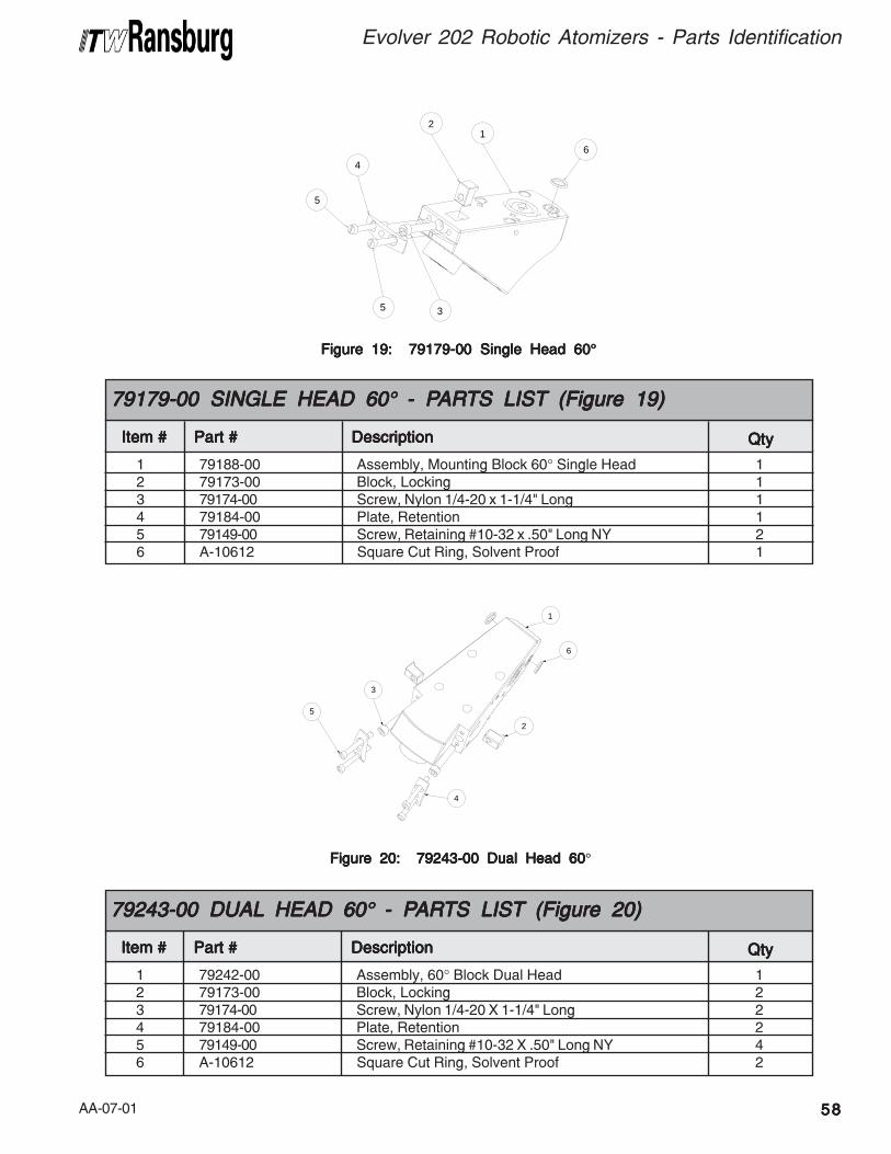
AA-07-01 5858585858
Evolver 202 Robotic Atomizers - Parts Identification
Figure 19: 79179-00 Single Head 60Figure 19: 79179-00 Single Head 60Figure 19: 79179-00 Single Head 60Figure 19: 79179-00 Single Head 60Figure 19: 79179-00 Single Head 60°°°°°
6
5
5
4
3
21
1 79188-00 Assembly, Mounting Block 60° Single Head 12 79173-00 Block, Locking 13 79174-00 Screw, Nylon 1/4-20 x 1-1/4" Long 14 79184-00 Plate, Retention 15 79149-00 Screw, Retaining #10-32 x .50" Long NY 26 A-10612 Square Cut Ring, Solvent Proof 1
Item #Item #Item #Item #Item #
79179-00 SINGLE HEAD 6079179-00 SINGLE HEAD 6079179-00 SINGLE HEAD 6079179-00 SINGLE HEAD 6079179-00 SINGLE HEAD 60° ° ° ° ° - P- P- P- P- PARARARARARTS LISTTS LISTTS LISTTS LISTTS LIST (Figure 19) (Figure 19) (Figure 19) (Figure 19) (Figure 19)
Part #Part #Part #Part #Part # DescriptionDescriptionDescriptionDescriptionDescription QtyQtyQtyQtyQty
Figure 20: 79243-00 Dual Head 60Figure 20: 79243-00 Dual Head 60Figure 20: 79243-00 Dual Head 60Figure 20: 79243-00 Dual Head 60Figure 20: 79243-00 Dual Head 60°
1 79242-00 Assembly, 60° Block Dual Head 12 79173-00 Block, Locking 23 79174-00 Screw, Nylon 1/4-20 X 1-1/4" Long 24 79184-00 Plate, Retention 25 79149-00 Screw, Retaining #10-32 X .50" Long NY 46 A-10612 Square Cut Ring, Solvent Proof 2
Item #Item #Item #Item #Item #
79243-00 DUAL79243-00 DUAL79243-00 DUAL79243-00 DUAL79243-00 DUAL HEAD 60 HEAD 60 HEAD 60 HEAD 60 HEAD 60° ° ° ° ° - P- P- P- P- PARARARARARTS LISTTS LISTTS LISTTS LISTTS LIST (Figure 20) (Figure 20) (Figure 20) (Figure 20) (Figure 20)
Part #Part #Part #Part #Part # DescriptionDescriptionDescriptionDescriptionDescription QtyQtyQtyQtyQty
6
1
2
3
5
4
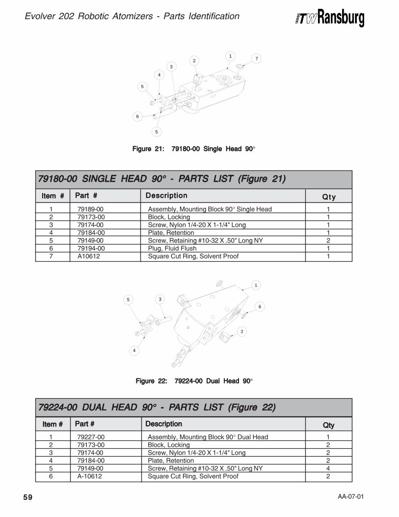
AA-07-01
Evolver 202 Robotic Atomizers - Parts Identification
5959595959
Figure 21: 79180-00 Single Head 90Figure 21: 79180-00 Single Head 90Figure 21: 79180-00 Single Head 90Figure 21: 79180-00 Single Head 90Figure 21: 79180-00 Single Head 90°
6
1 723
4
5
5
1 79189-00 Assembly, Mounting Block 90° Single Head 12 79173-00 Block, Locking 13 79174-00 Screw, Nylon 1/4-20 X 1-1/4" Long 14 79184-00 Plate, Retention 15 79149-00 Screw, Retaining #10-32 X .50" Long NY 26 79194-00 Plug, Fluid Flush 17 A10612 Square Cut Ring, Solvent Proof 1
Item #Item #Item #Item #Item # Part #Part #Part #Part #Part # DescriptionDescriptionDescriptionDescriptionDescription Q t yQ t yQ t yQ t yQ t y
79180-00 SINGLE HEAD 9079180-00 SINGLE HEAD 9079180-00 SINGLE HEAD 9079180-00 SINGLE HEAD 9079180-00 SINGLE HEAD 90° ° ° ° ° - P- P- P- P- PARARARARARTS LISTTS LISTTS LISTTS LISTTS LIST (Figure 21) (Figure 21) (Figure 21) (Figure 21) (Figure 21)
Figure 22: 79224-00 Dual Head 90Figure 22: 79224-00 Dual Head 90Figure 22: 79224-00 Dual Head 90Figure 22: 79224-00 Dual Head 90Figure 22: 79224-00 Dual Head 90°
6
4
1
3
2
5
1 79227-00 Assembly, Mounting Block 90° Dual Head 12 79173-00 Block, Locking 23 79174-00 Screw, Nylon 1/4-20 X 1-1/4" Long 24 79184-00 Plate, Retention 25 79149-00 Screw, Retaining #10-32 X .50" Long NY 46 A-10612 Square Cut Ring, Solvent Proof 2
Item #Item #Item #Item #Item #
79224-00 DUAL79224-00 DUAL79224-00 DUAL79224-00 DUAL79224-00 DUAL HEAD 90 HEAD 90 HEAD 90 HEAD 90 HEAD 90° ° ° ° ° - P- P- P- P- PARARARARARTS LISTTS LISTTS LISTTS LISTTS LIST (Figure 22) (Figure 22) (Figure 22) (Figure 22) (Figure 22)
Part #Part #Part #Part #Part # DescriptionDescriptionDescriptionDescriptionDescription QtyQtyQtyQtyQty

AA-07-01 6060606060
Evolver 202 Robotic Atomizers - Parts Identification
NOTESNOTESNOTESNOTESNOTES
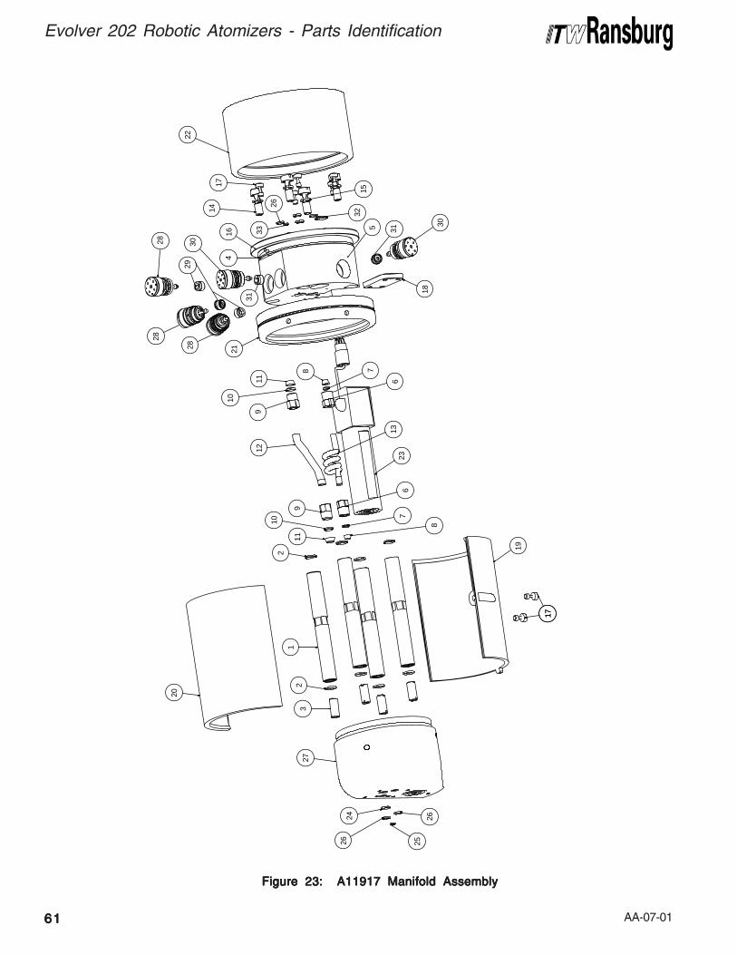
AA-07-01
Evolver 202 Robotic Atomizers - Parts Identification
6161616161
Figure 23: A11917 Manifold AssemblyFigure 23: A11917 Manifold AssemblyFigure 23: A11917 Manifold AssemblyFigure 23: A11917 Manifold AssemblyFigure 23: A11917 Manifold Assembly
32
33
26
15
1417
22
416
29
28
5
18
21
8 7
611
10
9
13
12
236
7
8
9
10
11
21
23
19
1717
20
25
24 26
26
27
30
31
28
2830
31
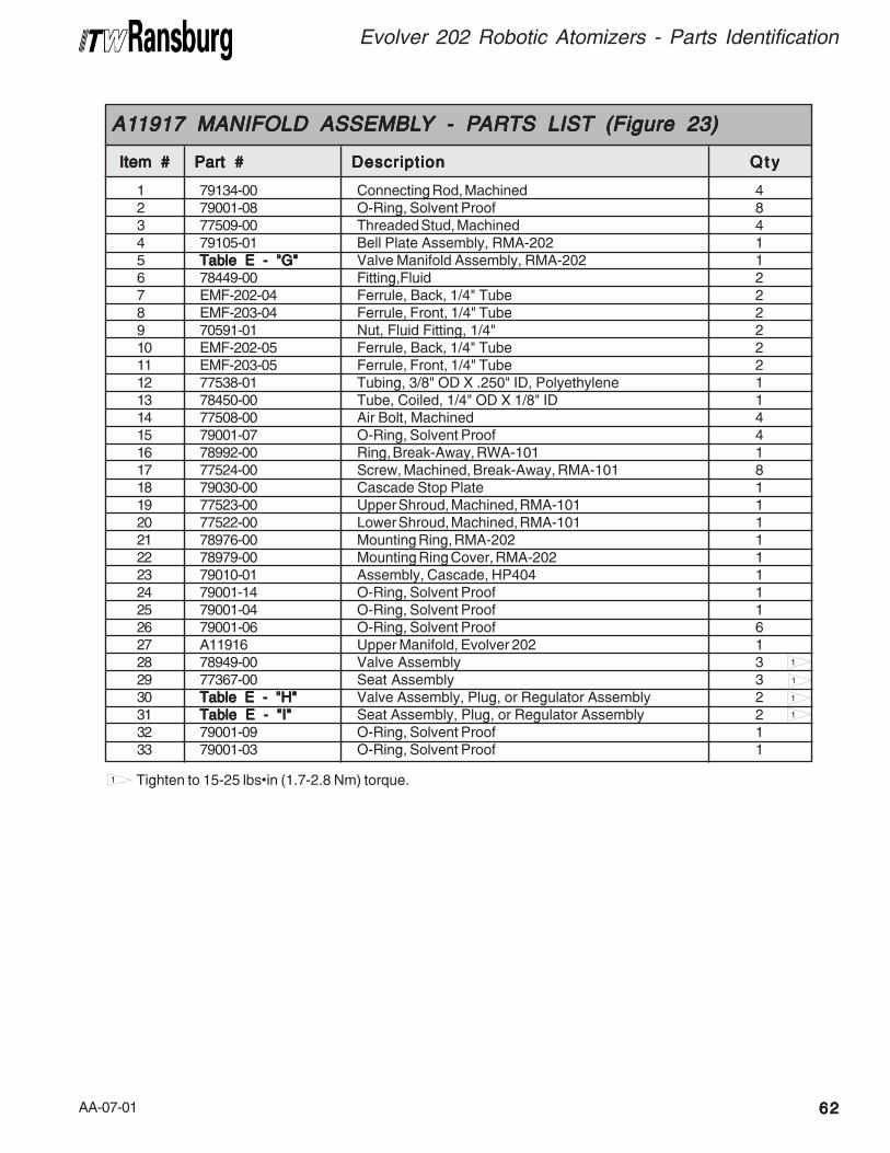
AA-07-01 6262626262
Evolver 202 Robotic Atomizers - Parts Identification
1
1
Tighten to 15-25 lbs•in (1.7-2.8 Nm) torque.
1
1
1
1 79134-00 Connecting Rod, Machined 42 79001-08 O-Ring, Solvent Proof 83 77509-00 Threaded Stud, Machined 44 79105-01 Bell Plate Assembly, RMA-202 15 Table E - "G"Table E - "G"Table E - "G"Table E - "G"Table E - "G" Valve Manifold Assembly, RMA-202 16 78449-00 Fitting,Fluid 27 EMF-202-04 Ferrule, Back, 1/4" Tube 28 EMF-203-04 Ferrule, Front, 1/4" Tube 29 70591-01 Nut, Fluid Fitting, 1/4" 210 EMF-202-05 Ferrule, Back, 1/4" Tube 211 EMF-203-05 Ferrule, Front, 1/4" Tube 212 77538-01 Tubing, 3/8" OD X .250" ID, Polyethylene 113 78450-00 Tube, Coiled, 1/4" OD X 1/8" ID 114 77508-00 Air Bolt, Machined 415 79001-07 O-Ring, Solvent Proof 416 78992-00 Ring, Break-Away, RWA-101 117 77524-00 Screw, Machined, Break-Away, RMA-101 818 79030-00 Cascade Stop Plate 119 77523-00 Upper Shroud, Machined, RMA-101 120 77522-00 Lower Shroud, Machined, RMA-101 121 78976-00 Mounting Ring, RMA-202 122 78979-00 Mounting Ring Cover, RMA-202 123 79010-01 Assembly, Cascade, HP404 124 79001-14 O-Ring, Solvent Proof 125 79001-04 O-Ring, Solvent Proof 126 79001-06 O-Ring, Solvent Proof 627 A11916 Upper Manifold, Evolver 202 128 78949-00 Valve Assembly 329 77367-00 Seat Assembly 330 Table E - "H"Table E - "H"Table E - "H"Table E - "H"Table E - "H" Valve Assembly, Plug, or Regulator Assembly 231 Table E - "I"Table E - "I"Table E - "I"Table E - "I"Table E - "I" Seat Assembly, Plug, or Regulator Assembly 232 79001-09 O-Ring, Solvent Proof 133 79001-03 O-Ring, Solvent Proof 1
Item #Item #Item #Item #Item #
A1A1A1A1A119171917191719171917 MANIFOLD ASSEMBL MANIFOLD ASSEMBL MANIFOLD ASSEMBL MANIFOLD ASSEMBL MANIFOLD ASSEMBLYYYYY - P - P - P - P - PARARARARARTS LISTTS LISTTS LISTTS LISTTS LIST (Figure 23) (Figure 23) (Figure 23) (Figure 23) (Figure 23)
Part #Part #Part #Part #Part # DescriptionDescriptionDescriptionDescriptionDescription Q t yQ t yQ t yQ t yQ t y
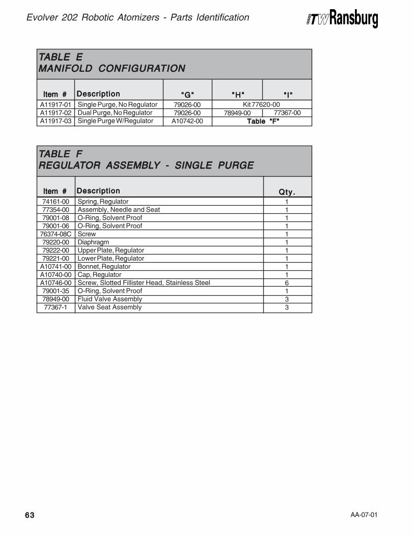
AA-07-01
Evolver 202 Robotic Atomizers - Parts Identification
6363636363
Kit 77620-00
TTTTTABLE EABLE EABLE EABLE EABLE EMANIFOLD CONFIGURAMANIFOLD CONFIGURAMANIFOLD CONFIGURAMANIFOLD CONFIGURAMANIFOLD CONFIGURATIONTIONTIONTIONTION
A11917-01A11917-02A11917-03
DescriptionDescriptionDescriptionDescriptionDescription
Single Purge, No RegulatorDual Purge, No RegulatorSingle Purge W/Regulator
"G""G""G""G""G"
79026-0079026-00
A10742-00
"H""H""H""H""H"
78949-00
"I""I""I""I""I"
77367-00
Item #Item #Item #Item #Item #
Table "F"Table "F"Table "F"Table "F"Table "F"
TTTTTABLE FABLE FABLE FABLE FABLE FREGULAREGULAREGULAREGULAREGULATTTTTOR ASSEMBLOR ASSEMBLOR ASSEMBLOR ASSEMBLOR ASSEMBLYYYYY - SINGLE PURGE - SINGLE PURGE - SINGLE PURGE - SINGLE PURGE - SINGLE PURGE
74161-0077354-0079001-0879001-06
76374-08C79220-0079222-0079221-00
A10741-00A10740-00A10746-0079001-3578949-0077367-1
DescriptionDescriptionDescriptionDescriptionDescription
Spring, RegulatorAssembly, Needle and SeatO-Ring, Solvent ProofO-Ring, Solvent ProofScrewDiaphragmUpper Plate, RegulatorLower Plate, RegulatorBonnet, RegulatorCap, RegulatorScrew, Slotted Fillister Head, Stainless SteelO-Ring, Solvent ProofFluid Valve AssemblyValve Seat Assembly
Qty .Qty .Qty .Qty .Qty .
11111111116133
Item #Item #Item #Item #Item #
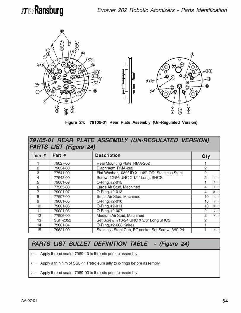
AA-07-01 6464646464
Evolver 202 Robotic Atomizers - Parts Identification
Figure 24: 79105-01 Rear Plate Assembly (Un-Regulated Version)Figure 24: 79105-01 Rear Plate Assembly (Un-Regulated Version)Figure 24: 79105-01 Rear Plate Assembly (Un-Regulated Version)Figure 24: 79105-01 Rear Plate Assembly (Un-Regulated Version)Figure 24: 79105-01 Rear Plate Assembly (Un-Regulated Version)
2
1 79027-00 Rear Mounting Plate, RMA-202 12 79034-00 Diaphragm, RMA-202 23 77541-00 Flat Washer, .089" ID X .149" OD, Stainless Steel 24 77543-00 Screw, #2-56 UNC X 1/4" Long, SHCS 25 79001-09 O-Ring, #2-015 16 77505-00 Large Air Stud, Machined 47 79001-07 O-Ring, #2-013 48 77507-00 Small Air Stud, Machined 109 79001-05 O-Ring, #2-010 1010 79001-06 O-Ring, #2-011 1011 79001-03 O-Ring, #2-007 212 77506-00 Medium Air Stud, Machined 213 SSF-2052 Set Screw, #10-24 UNC X 3/8" Long SHCS 214 79001-04 O-Ring, #2-008,Kalrez 115 79621-00 Stainless Steel Cup, PT socket Set Screw, 3/8"-24 1
Item #Item #Item #Item #Item #
79105-01 REAR PLA79105-01 REAR PLA79105-01 REAR PLA79105-01 REAR PLA79105-01 REAR PLATE ASSEMBLTE ASSEMBLTE ASSEMBLTE ASSEMBLTE ASSEMBLYYYYY (UN-REGULA (UN-REGULA (UN-REGULA (UN-REGULA (UN-REGULATED VERSION)TED VERSION)TED VERSION)TED VERSION)TED VERSION)PPPPPARARARARARTS LISTTS LISTTS LISTTS LISTTS LIST (Figure 24) (Figure 24) (Figure 24) (Figure 24) (Figure 24)
Part #Part #Part #Part #Part # DescriptionDescriptionDescriptionDescriptionDescription Q t yQ t yQ t yQ t yQ t y
1
2
1
2
1
2
1
3
2
Apply thread sealer 7969-10 to threads prior to assembly.
Apply a thin film of SSL-11 Petroleum jelly to o-rings before assembly
Apply thread sealer 7969-03 to threads prior to assembly.
PPPPPARARARARARTS LISTTS LISTTS LISTTS LISTTS LIST BULLET BULLET BULLET BULLET BULLET DEFINITION T DEFINITION T DEFINITION T DEFINITION T DEFINITION TABLE - (Figure 24)ABLE - (Figure 24)ABLE - (Figure 24)ABLE - (Figure 24)ABLE - (Figure 24)
1
2
3
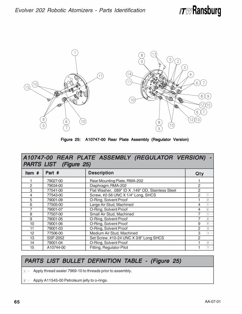
AA-07-01
Evolver 202 Robotic Atomizers - Parts Identification
6565656565
Figure 25: A10747-00 Rear Plate Assembly (Regulator Version)Figure 25: A10747-00 Rear Plate Assembly (Regulator Version)Figure 25: A10747-00 Rear Plate Assembly (Regulator Version)Figure 25: A10747-00 Rear Plate Assembly (Regulator Version)Figure 25: A10747-00 Rear Plate Assembly (Regulator Version)
Apply thread sealer 7969-10 to threads prior to assembly.
Apply A11545-00 Petroleum jelly to o-rings.
PPPPPARARARARARTS LISTTS LISTTS LISTTS LISTTS LIST BULLET BULLET BULLET BULLET BULLET DEFINITION T DEFINITION T DEFINITION T DEFINITION T DEFINITION TABLE - (Figure 25)ABLE - (Figure 25)ABLE - (Figure 25)ABLE - (Figure 25)ABLE - (Figure 25)
1
2
2
1 79027-00 Rear Mounting Plate, RMA-202 12 79034-00 Diaphragm, RMA-202 23 77541-00 Flat Washer, .089" ID X .149" OD, Stainless Steel 24 77543-00 Screw, #2-56 UNC X 1/4" Long, SHCS 25 79001-09 O-Ring, Solvent Proof 16 77505-00 Large Air Stud, Machined 47 79001-07 O-Ring, Solvent Proof 48 77507-00 Small Air Stud, Machined 79 79001-05 O-Ring, Solvent Proof 710 79001-06 O-Ring, Solvent Proof 911 79001-03 O-Ring, Solvent Proof 212 77506-00 Medium Air Stud, Machined 313 SSF-2052 Set Screw, #10-24 UNC X 3/8" Long SHCS 214 79001-04 O-Ring, Solvent Proof 115 A10744-00 Fitting, Regulator Pilot 1
Item #Item #Item #Item #Item #
A10747-00 REAR PLAA10747-00 REAR PLAA10747-00 REAR PLAA10747-00 REAR PLAA10747-00 REAR PLATE ASSEMBLTE ASSEMBLTE ASSEMBLTE ASSEMBLTE ASSEMBLYYYYY (REGULA (REGULA (REGULA (REGULA (REGULATTTTTOR VERSION) -OR VERSION) -OR VERSION) -OR VERSION) -OR VERSION) -PPPPPARARARARARTS LISTTS LISTTS LISTTS LISTTS LIST (Figure 25) (Figure 25) (Figure 25) (Figure 25) (Figure 25)
Part #Part #Part #Part #Part # DescriptionDescriptionDescriptionDescriptionDescription Q t yQ t yQ t yQ t yQ t y
1
2
1
2
1
2
1
2
1
2
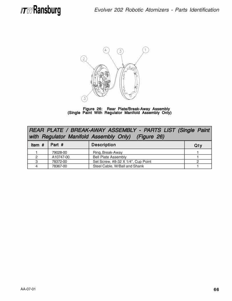
AA-07-01 6666666666
Evolver 202 Robotic Atomizers - Parts Identification
Figure 26: Rear Plate/Break-Away AssemblyFigure 26: Rear Plate/Break-Away AssemblyFigure 26: Rear Plate/Break-Away AssemblyFigure 26: Rear Plate/Break-Away AssemblyFigure 26: Rear Plate/Break-Away Assembly(Single Paint With Regulator Manifold Assembly Only)(Single Paint With Regulator Manifold Assembly Only)(Single Paint With Regulator Manifold Assembly Only)(Single Paint With Regulator Manifold Assembly Only)(Single Paint With Regulator Manifold Assembly Only)
1 79028-00 Ring, Break-Away 12 A10747-00 Bell Plate Assembly 13 78372-00 Set Screw, #8-32 X 1/4", Cup Point 24 78367-00 Steel Cable, W/Ball and Shank 1
Item #Item #Item #Item #Item #
REAR PLAREAR PLAREAR PLAREAR PLAREAR PLATE / BREAK-ATE / BREAK-ATE / BREAK-ATE / BREAK-ATE / BREAK-AWWWWWAAAAAYYYYY ASSEMBL ASSEMBL ASSEMBL ASSEMBL ASSEMBLYYYYY - - - - - PPPPPARARARARARTS LISTTS LISTTS LISTTS LISTTS LIST (Single Paint (Single Paint (Single Paint (Single Paint (Single Paintwith Regulator Manifold Assembly Only) (Figure 26)with Regulator Manifold Assembly Only) (Figure 26)with Regulator Manifold Assembly Only) (Figure 26)with Regulator Manifold Assembly Only) (Figure 26)with Regulator Manifold Assembly Only) (Figure 26)
Part #Part #Part #Part #Part # DescriptionDescriptionDescriptionDescriptionDescription Q t yQ t yQ t yQ t yQ t y

AA-07-01
Evolver 202 Robotic Atomizers - Maintenance
6767676767
81313
3420
3836
3012
2839
3735
4123
4331
15 25 27 29 45
516
1751
1352
1424
497
1850
32
16
42 1 5 33
48
47
1122
Figure 27: 79106-XXXXXXX Tubing Bundle Assembly (English)Figure 27: 79106-XXXXXXX Tubing Bundle Assembly (English)Figure 27: 79106-XXXXXXX Tubing Bundle Assembly (English)Figure 27: 79106-XXXXXXX Tubing Bundle Assembly (English)Figure 27: 79106-XXXXXXX Tubing Bundle Assembly (English)
> Do not over-tighten the 77544-01 [13]
beyond the maximum 10 lbs•in force.
C A U T I O NC A U T I O NC A U T I O NC A U T I O NC A U T I O N!!!!!T
orq
ue
to
To
rqu
e
toT
orq
ue
to
To
rqu
e
toT
orq
ue
to
10
lb
s-i
n1
0
lbs
-in
10
lb
s-i
n1
0
lbs
-in
10
lb
s-i
n
ma
x.
ma
x.
ma
x.
ma
x.
ma
x.
To
rqu
e
toT
orq
ue
to
To
rqu
e
toT
orq
ue
to
To
rqu
e
to
10
lb
s-i
n1
0
lbs
-in
10
lb
s-i
n1
0
lbs
-in
10
lb
s-i
n
ma
x.
ma
x.
ma
x.
ma
x.
ma
x.
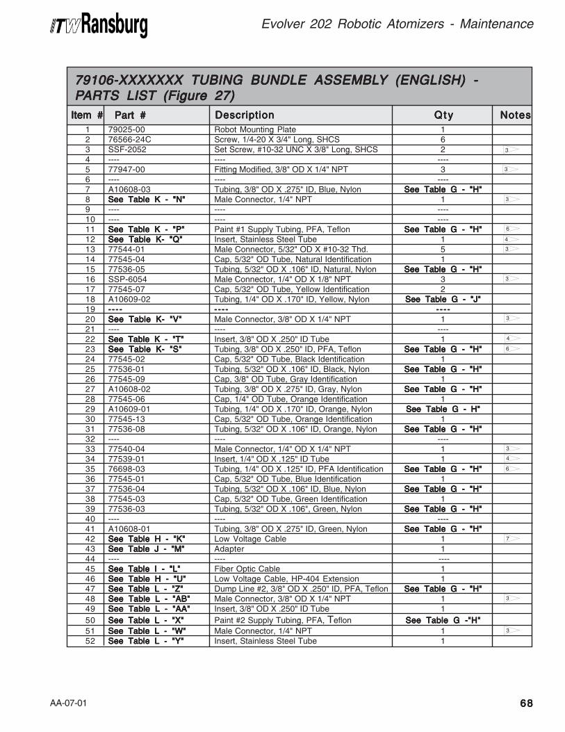
AA-07-01 6868686868
Evolver 202 Robotic Atomizers - Maintenance
6
4
6
3
4
3
3
1 79025-00 Robot Mounting Plate 12 76566-24C Screw, 1/4-20 X 3/4" Long, SHCS 63 SSF-2052 Set Screw, #10-32 UNC X 3/8" Long, SHCS 24 ---- ---- ----5 77947-00 Fitting Modified, 3/8" OD X 1/4" NPT 36 ---- ---- ----7 A10608-03 Tubing, 3/8" OD X .275" ID, Blue, Nylon See Table G - "H"See Table G - "H"See Table G - "H"See Table G - "H"See Table G - "H"8 See Table K - "N"See Table K - "N"See Table K - "N"See Table K - "N"See Table K - "N" Male Connector, 1/4" NPT 19 ---- ---- ----10 ---- ---- ----11 See Table K - "P"See Table K - "P"See Table K - "P"See Table K - "P"See Table K - "P" Paint #1 Supply Tubing, PFA, Teflon See Table G - "H"See Table G - "H"See Table G - "H"See Table G - "H"See Table G - "H"12 See Table K- "Q"See Table K- "Q"See Table K- "Q"See Table K- "Q"See Table K- "Q" Insert, Stainless Steel Tube 113 77544-01 Male Connector, 5/32" OD X #10-32 Thd. 514 77545-04 Cap, 5/32" OD Tube, Natural Identification 115 77536-05 Tubing, 5/32" OD X .106" ID, Natural, Nylon See Table G - "H"See Table G - "H"See Table G - "H"See Table G - "H"See Table G - "H"16 SSP-6054 Male Connector, 1/4" OD X 1/8" NPT 317 77545-07 Cap, 5/32" OD Tube, Yellow Identification 218 A10609-02 Tubing, 1/4" OD X .170" ID, Yellow, Nylon See Table G - "J"See Table G - "J"See Table G - "J"See Table G - "J"See Table G - "J"19 -- - -- - - -- - - -- - - -- - - - - - - -- - - -- - - -- - - -- - - - - - - -- - - -- - - -- - - -- - - -20 See Table K- "V"See Table K- "V"See Table K- "V"See Table K- "V"See Table K- "V" Male Connector, 3/8" OD X 1/4" NPT 121 ---- ---- ----22 See Table K - "T"See Table K - "T"See Table K - "T"See Table K - "T"See Table K - "T" Insert, 3/8" OD X .250" ID Tube 123 See Table K- "S"See Table K- "S"See Table K- "S"See Table K- "S"See Table K- "S" Tubing, 3/8" OD X .250" ID, PFA, Teflon See Table G - "H"See Table G - "H"See Table G - "H"See Table G - "H"See Table G - "H"24 77545-02 Cap, 5/32" OD Tube, Black Identification 125 77536-01 Tubing, 5/32" OD X .106" ID, Black, Nylon See Table G - "H"See Table G - "H"See Table G - "H"See Table G - "H"See Table G - "H"26 77545-09 Cap, 3/8" OD Tube, Gray Identification 127 A10608-02 Tubing, 3/8" OD X .275" ID, Gray, Nylon See Table G - "H"See Table G - "H"See Table G - "H"See Table G - "H"See Table G - "H"28 77545-06 Cap, 1/4" OD Tube, Orange Identification 129 A10609-01 Tubing, 1/4" OD X .170" ID, Orange, Nylon See Table G - H"See Table G - H"See Table G - H"See Table G - H"See Table G - H"30 77545-13 Cap, 5/32" OD Tube, Orange Identification 131 77536-08 Tubing, 5/32" OD X .106" ID, Orange, Nylon See Table G - "H"See Table G - "H"See Table G - "H"See Table G - "H"See Table G - "H"32 ---- ---- ----33 77540-04 Male Connector, 1/4" OD X 1/4" NPT 134 77539-01 Insert, 1/4" OD X .125" ID Tube 135 76698-03 Tubing, 1/4" OD X .125" ID, PFA Identification See Table G - "H"See Table G - "H"See Table G - "H"See Table G - "H"See Table G - "H"36 77545-01 Cap, 5/32" OD Tube, Blue Identification 137 77536-04 Tubing, 5/32" OD X .106" ID, Blue, Nylon See Table G - "H"See Table G - "H"See Table G - "H"See Table G - "H"See Table G - "H"38 77545-03 Cap, 5/32" OD Tube, Green Identification 139 77536-03 Tubing, 5/32" OD X .106", Green, Nylon See Table G - "H"See Table G - "H"See Table G - "H"See Table G - "H"See Table G - "H"40 ---- ---- ----41 A10608-01 Tubing, 3/8" OD X .275" ID, Green, Nylon See Table G - "H"See Table G - "H"See Table G - "H"See Table G - "H"See Table G - "H"42 See Table H - "K"See Table H - "K"See Table H - "K"See Table H - "K"See Table H - "K" Low Voltage Cable 143 See Table J - "M"See Table J - "M"See Table J - "M"See Table J - "M"See Table J - "M" Adapter 144 ---- ---- ----45 See Table I - "L"See Table I - "L"See Table I - "L"See Table I - "L"See Table I - "L" Fiber Optic Cable 146 See Table H - "U"See Table H - "U"See Table H - "U"See Table H - "U"See Table H - "U" Low Voltage Cable, HP-404 Extension 147 See Table L - "Z"See Table L - "Z"See Table L - "Z"See Table L - "Z"See Table L - "Z" Dump Line #2, 3/8" OD X .250" ID, PFA, Teflon See Table G - "H"See Table G - "H"See Table G - "H"See Table G - "H"See Table G - "H"48 See Table L - "AB"See Table L - "AB"See Table L - "AB"See Table L - "AB"See Table L - "AB" Male Connector, 3/8" OD X 1/4" NPT 149 See Table L - "AA"See Table L - "AA"See Table L - "AA"See Table L - "AA"See Table L - "AA" Insert, 3/8" OD X .250" ID Tube 1
50 See Table L - "X"See Table L - "X"See Table L - "X"See Table L - "X"See Table L - "X" Paint #2 Supply Tubing, PFA, Teflon See Table G -"H"See Table G -"H"See Table G -"H"See Table G -"H"See Table G -"H"
51 See Table L - "W"See Table L - "W"See Table L - "W"See Table L - "W"See Table L - "W" Male Connector, 1/4" NPT 152 See Table L - "Y"See Table L - "Y"See Table L - "Y"See Table L - "Y"See Table L - "Y" Insert, Stainless Steel Tube 1
Item #Item #Item #Item #Item #
79106-XXXXXXX TUBING BUNDLE ASSEMBL79106-XXXXXXX TUBING BUNDLE ASSEMBL79106-XXXXXXX TUBING BUNDLE ASSEMBL79106-XXXXXXX TUBING BUNDLE ASSEMBL79106-XXXXXXX TUBING BUNDLE ASSEMBLYYYYY (ENGLISH) - (ENGLISH) - (ENGLISH) - (ENGLISH) - (ENGLISH) -PPPPPARARARARARTS LISTTS LISTTS LISTTS LISTTS LIST (Figure 27) (Figure 27) (Figure 27) (Figure 27) (Figure 27)
Part #Part #Part #Part #Part # DescriptionDescriptionDescriptionDescriptionDescription Q t yQ t yQ t yQ t yQ t y NotesNotesNotesNotesNotes
3
7
6
4
3
3
3
3
3
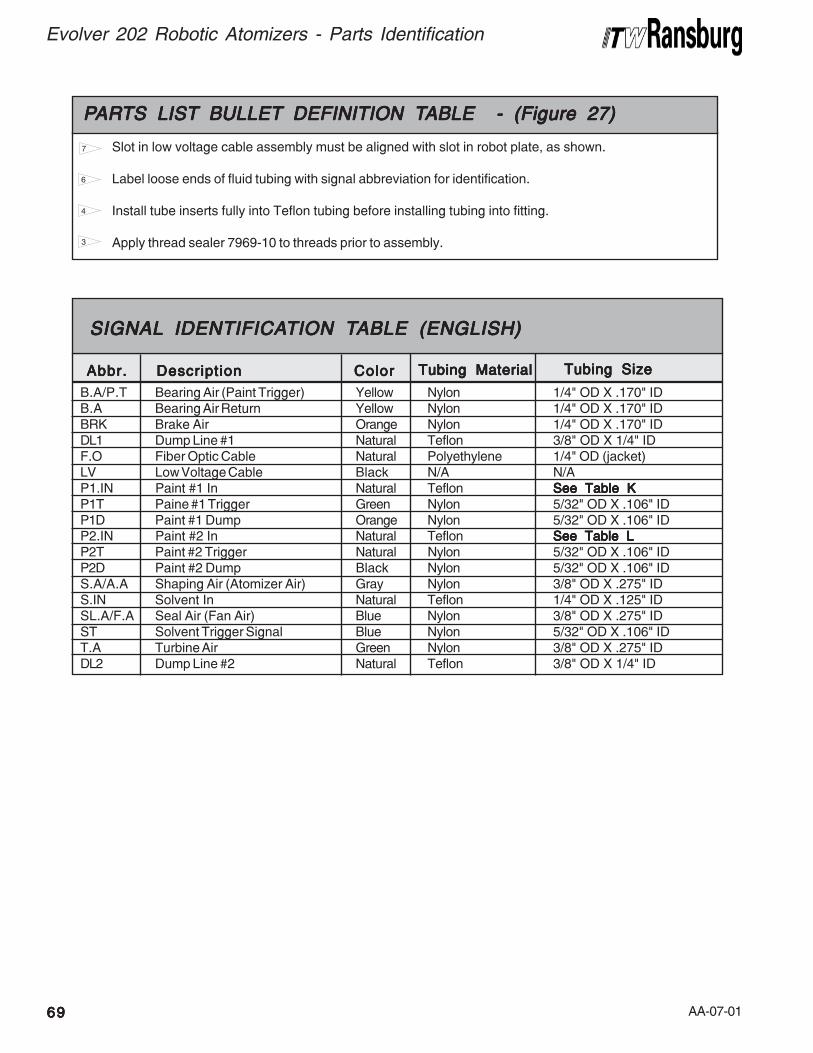
AA-07-016969696969
Evolver 202 Robotic Atomizers - Parts Identification
Tubing MaterialTubing MaterialTubing MaterialTubing MaterialTubing Material Tubing SizeTubing SizeTubing SizeTubing SizeTubing Size
B.A/P.T Bearing Air (Paint Trigger) Yellow Nylon 1/4" OD X .170" IDB.A Bearing Air Return Yellow Nylon 1/4" OD X .170" IDBRK Brake Air Orange Nylon 1/4" OD X .170" IDDL1 Dump Line #1 Natural Teflon 3/8" OD X 1/4" IDF.O Fiber Optic Cable Natural Polyethylene 1/4" OD (jacket)LV Low Voltage Cable Black N/A N/AP1.IN Paint #1 In Natural Teflon See Table KSee Table KSee Table KSee Table KSee Table KP1T Paine #1 Trigger Green Nylon 5/32" OD X .106" IDP1D Paint #1 Dump Orange Nylon 5/32" OD X .106" IDP2.IN Paint #2 In Natural Teflon See Table LSee Table LSee Table LSee Table LSee Table LP2T Paint #2 Trigger Natural Nylon 5/32" OD X .106" IDP2D Paint #2 Dump Black Nylon 5/32" OD X .106" IDS.A/A.A Shaping Air (Atomizer Air) Gray Nylon 3/8" OD X .275" IDS.IN Solvent In Natural Teflon 1/4" OD X .125" IDSL.A/F.A Seal Air (Fan Air) Blue Nylon 3/8" OD X .275" IDST Solvent Trigger Signal Blue Nylon 5/32" OD X .106" IDT.A Turbine Air Green Nylon 3/8" OD X .275" IDDL2 Dump Line #2 Natural Teflon 3/8" OD X 1/4" ID
SIGNALSIGNALSIGNALSIGNALSIGNAL IDENTIFICA IDENTIFICA IDENTIFICA IDENTIFICA IDENTIFICATION TTION TTION TTION TTION TABLE (ENGLISH)ABLE (ENGLISH)ABLE (ENGLISH)ABLE (ENGLISH)ABLE (ENGLISH)
Abbr.Abbr.Abbr.Abbr.Abbr. DescriptionDescriptionDescriptionDescriptionDescription ColorColorColorColorColor
Slot in low voltage cable assembly must be aligned with slot in robot plate, as shown.
Label loose ends of fluid tubing with signal abbreviation for identification.
Install tube inserts fully into Teflon tubing before installing tubing into fitting.
Apply thread sealer 7969-10 to threads prior to assembly.
PPPPPARARARARARTS LISTTS LISTTS LISTTS LISTTS LIST BULLET BULLET BULLET BULLET BULLET DEFINITION T DEFINITION T DEFINITION T DEFINITION T DEFINITION TABLE - (Figure 27)ABLE - (Figure 27)ABLE - (Figure 27)ABLE - (Figure 27)ABLE - (Figure 27)
7
6
4
3
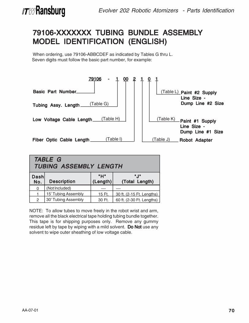
AA-07-01 7070707070
Evolver 202 Robotic Atomizers - Parts Identification
79106-79106-79106-79106-79106-XXXXXXXXXXXXXXXXXXXXXXXXXXXXXXXXXXX TUBING BUNDLE ASSEMBL TUBING BUNDLE ASSEMBL TUBING BUNDLE ASSEMBL TUBING BUNDLE ASSEMBL TUBING BUNDLE ASSEMBLYYYYY
MODELMODELMODELMODELMODEL IDENTIFICA IDENTIFICA IDENTIFICA IDENTIFICA IDENTIFICATION (ENGLISH)TION (ENGLISH)TION (ENGLISH)TION (ENGLISH)TION (ENGLISH)
When ordering, use 79106-ABBCDEF as indicated by Tables G thru L. Seven digits must follow the basic part number, for example:
79106 - 1 00 2 1 0 1 79106 - 1 00 2 1 0 1 79106 - 1 00 2 1 0 1 79106 - 1 00 2 1 0 1 79106 - 1 00 2 1 0 1
Tubing Assy. LengthTubing Assy. LengthTubing Assy. LengthTubing Assy. LengthTubing Assy. Length
Basic Part NumberBasic Part NumberBasic Part NumberBasic Part NumberBasic Part Number
Paint #1 SupplyPaint #1 SupplyPaint #1 SupplyPaint #1 SupplyPaint #1 Supply
Line Size -Line Size -Line Size -Line Size -Line Size -
Dump Line #1 SizeDump Line #1 SizeDump Line #1 SizeDump Line #1 SizeDump Line #1 Size
Paint #2 SupplyPaint #2 SupplyPaint #2 SupplyPaint #2 SupplyPaint #2 Supply
Line Size -Line Size -Line Size -Line Size -Line Size -
Dump Line #2 SizeDump Line #2 SizeDump Line #2 SizeDump Line #2 SizeDump Line #2 Size
Low Voltage Cable LengthLow Voltage Cable LengthLow Voltage Cable LengthLow Voltage Cable LengthLow Voltage Cable Length
Fiber Optic Cable LengthFiber Optic Cable LengthFiber Optic Cable LengthFiber Optic Cable LengthFiber Optic Cable Length Robot AdapterRobot AdapterRobot AdapterRobot AdapterRobot Adapter
(Table G)
(Table H)
(Table I)
(Table L)
(Table K)
(Table J)
----
30 ft. (2-15 Ft. Lengths)
60 ft. (2-30 Ft. Lengths)
(Not Included)
15' Tubing Assembly
30' Tubing Assembly
TTTTTABLE GABLE GABLE GABLE GABLE GTUBING ASSEMBLTUBING ASSEMBLTUBING ASSEMBLTUBING ASSEMBLTUBING ASSEMBLYYYYY LENGTH LENGTH LENGTH LENGTH LENGTH
0
1
2
----
15 Ft.
30 Ft.
DashDashDashDashDashNo.No.No.No.No.
"H""H""H""H""H"(Length)(Length)(Length)(Length)(Length)DescriptionDescriptionDescriptionDescriptionDescription
"J""J""J""J""J"(Total Length)(Total Length)(Total Length)(Total Length)(Total Length)
NOTE: To allow tubes to move freely in the robot wrist and arm,remove all the black electrical tape holding tubing bundle together.This tape is for shipping purposes only. Remove any gummyresidue left by tape by wiping with a mild solvent. Do NotDo NotDo NotDo NotDo Not use anysolvent to wipe outer sheathing of low voltage cable.
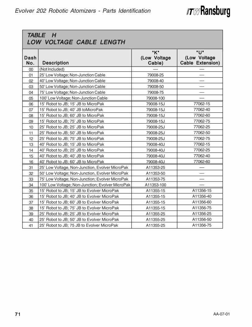
AA-07-017171717171
Evolver 202 Robotic Atomizers - Parts Identification
(Not Included)
25' Low Voltage; Non-Junction Cable
40' Low Voltage; Non-Junction Cable
50' Low Voltage; Non-Junction Cable
75' Low Voltage; Non-Junction Cable
100' Low Voltage; Non-Junction Cable
15' Robot to JB; 15' JB to MicroPak
15' Robot to JB; 40' JB toMicroPak
15' Robot to JB; 60' JB to MicroPak
15' Robot to JB; 75' JB to MicroPak
25' Robot to JB; 25' JB to MicroPak
25' Robot to JB; 50' JB to MicroPak
25' Robot to JB; 75' JB to MicroPak
40' Robot to JB; 15' JB to MicroPak
40' Robot to JB; 25' JB to MicroPak
40' Robot to JB; 40' JB to MicroPak
40' Robot to JB; 60' JB to MicroPak
25' Low Voltage, Non-Junction, Evolver MicroPak
50' Low Voltage; Non-Junction, Evolver MicroPak
75' Low Voltage; Non-Junction; Evolver MicroPak
100' Low Voltage; Non-Junction; Evolver MicroPak
15' Robot to JB; 15' JB to Evolver MicroPak
15' Robot to JB; 40' JB to Evolver MicroPak
15' Robot to JB; 60' JB to Evolver MicroPak
15' Robot to JB; 75' JB to Evolver MicroPak
25' Robot to JB; 25' JB to Evolver MicroPak
25' Robot to JB; 50' JB to Evolver MicroPak
25' Robot to JB; 75 JB to Evolver MicroPak
TTTTTABLE HABLE HABLE HABLE HABLE HLOW VOLLOW VOLLOW VOLLOW VOLLOW VOLTTTTTAGE CABLE LENGTHAGE CABLE LENGTHAGE CABLE LENGTHAGE CABLE LENGTHAGE CABLE LENGTH
00
01
02
03
04
05
06
07
08
09
10
11
12
13
14
15
16
31
32
33
34
35
36
37
38
39
40
41
----
79008-25
79008-40
79008-50
79008-75
79008-100
79008-15J
79008-15J
79008-15J
79008-15J
79008-25J
79008-25J
79008-25J
79008-40J
79008-40J
79008-40J
79008-40J
A11353-25
A11353-50
A11353-75
A11353-100
A11355-15
A11355-15
A11355-15
A11355-15
A11355-25
A11355-25
A11355-25
DashDashDashDashDashNo.No.No.No.No.
"K""K""K""K""K"(Low Voltage(Low Voltage(Low Voltage(Low Voltage(Low Voltage
Cable)Cable)Cable)Cable)Cable)DescriptionDescriptionDescriptionDescriptionDescription
----
----
----
----
----
----
77062-15
77062-40
77062-60
77062-75
77062-25
77062-50
77062-75
77062-15
77062-25
77062-40
77062-60
----
----
----
----
A11356-15
A11356-40
A11356-60
A11356-75
A11356-25
A11356-50
A11356-75
"U""U""U""U""U"(Low Voltage(Low Voltage(Low Voltage(Low Voltage(Low Voltage
Cable Extension)Cable Extension)Cable Extension)Cable Extension)Cable Extension)
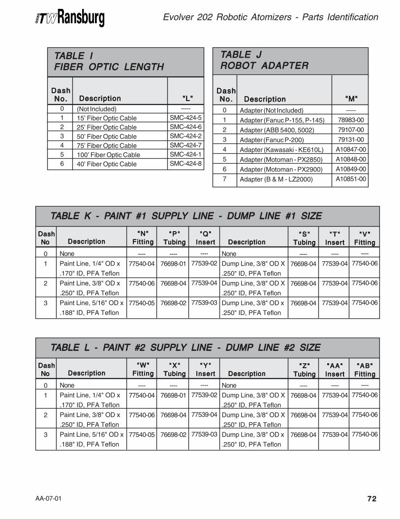
AA-07-01 7272727272
Evolver 202 Robotic Atomizers - Parts Identification
(Not Included)
15' Fiber Optic Cable
25' Fiber Optic Cable
50' Fiber Optic Cable
75' Fiber Optic Cable
100' Fiber Optic Cable
40' Fiber Optic Cable
TTTTTABLE IABLE IABLE IABLE IABLE IFIBER OPTIC LENGTHFIBER OPTIC LENGTHFIBER OPTIC LENGTHFIBER OPTIC LENGTHFIBER OPTIC LENGTH
0
1
2
3
4
5
6
-----
SMC-424-5
SMC-424-6
SMC-424-2
SMC-424-7
SMC-424-1
SMC-424-8
DashDashDashDashDashNo.No.No.No.No. "L""L""L""L""L"DescriptionDescriptionDescriptionDescriptionDescription
Adapter (Not Included)
Adapter (Fanuc P-155, P-145)
Adapter (ABB 5400, 5002)
Adapter (Fanuc P-200)
Adapter (Kawasaki - KE610L)
Adapter (Motoman - PX2850)
Adapter (Motoman - PX2900)
Adapter (B & M - LZ2000)
TTTTTABLE JABLE JABLE JABLE JABLE JROBOT ADAPTERROBOT ADAPTERROBOT ADAPTERROBOT ADAPTERROBOT ADAPTER
0
1
2
3
4
5
6
7
-----
78983-00
79107-00
79131-00
A10847-00
A10848-00
A10849-00
A10851-00
DashDashDashDashDashNo.No.No.No.No. "M""M""M""M""M"DescriptionDescriptionDescriptionDescriptionDescription
None
Paint Line, 1/4" OD x
.170" ID, PFA Teflon
Paint Line, 3/8" OD x
.250" ID, PFA Teflon
Paint Line, 5/16" OD x
.188" ID, PFA Teflon
TTTTTABLE K - PABLE K - PABLE K - PABLE K - PABLE K - PAINTAINTAINTAINTAINT #1 SUPPL #1 SUPPL #1 SUPPL #1 SUPPL #1 SUPPLYYYYY LINE - DUMP LINE - DUMP LINE - DUMP LINE - DUMP LINE - DUMP LINE #1 SIZE LINE #1 SIZE LINE #1 SIZE LINE #1 SIZE LINE #1 SIZE
0
1
2
3
DashDashDashDashDash
No No No No No DescriptionDescriptionDescriptionDescriptionDescription
----
77540-04
77540-06
77540-05
"N""N""N""N""N"
Fitt ingFitt ingFitt ingFitt ingFitt ing
----
76698-01
76698-04
76698-02
"P""P ""P ""P ""P "
TubingTubingTubingTubingTubing
----
77539-02
77539-04
77539-03
"Q""Q""Q""Q""Q"
InsertInsertInsertInsertInsert
None
Dump Line, 3/8" OD X
.250" ID, PFA Teflon
Dump Line, 3/8" OD X
.250" ID, PFA Teflon
Dump Line, 3/8" OD x
.250" ID, PFA Teflon
DescriptionDescriptionDescriptionDescriptionDescription
----
76698-04
76698-04
76698-04
"S""S ""S ""S ""S "
TubingTubingTubingTubingTubing
----
77539-04
77539-04
77539-04
"T""T""T""T""T"
InsertInsertInsertInsertInsert
----
77540-06
77540-06
77540-06
"V""V ""V ""V ""V "
Fitt ingFitt ingFitt ingFitt ingFitt ing
None
Paint Line, 1/4" OD x
.170" ID, PFA Teflon
Paint Line, 3/8" OD x
.250" ID, PFA Teflon
Paint Line, 5/16" OD x
.188" ID, PFA Teflon
TTTTTABLE LABLE LABLE LABLE LABLE L - P - P - P - P - PAINTAINTAINTAINTAINT #2 SUPPL #2 SUPPL #2 SUPPL #2 SUPPL #2 SUPPLYYYYY LINE - DUMP LINE - DUMP LINE - DUMP LINE - DUMP LINE - DUMP LINE #2 SIZE LINE #2 SIZE LINE #2 SIZE LINE #2 SIZE LINE #2 SIZE
0
1
2
3
DashDashDashDashDash
No No No No No DescriptionDescriptionDescriptionDescriptionDescription
----
77540-04
77540-06
77540-05
"W""W""W""W""W"
Fitt ingFitt ingFitt ingFitt ingFitt ing
----
76698-01
76698-04
76698-02
"X""X ""X ""X ""X "
TubingTubingTubingTubingTubing
----
77539-02
77539-04
77539-03
"Y""Y ""Y ""Y ""Y "
InsertInsertInsertInsertInsert
None
Dump Line, 3/8" OD X
.250" ID, PFA Teflon
Dump Line, 3/8" OD X
.250" ID, PFA Teflon
Dump Line, 3/8" OD x
.250" ID, PFA Teflon
DescriptionDescriptionDescriptionDescriptionDescription
----
76698-04
76698-04
76698-04
"Z""Z""Z""Z""Z"
TubingTubingTubingTubingTubing
----
77539-04
77539-04
77539-04
"AA""AA""AA""AA""AA"
InsertInsertInsertInsertInsert
----
77540-06
77540-06
77540-06
"AB""AB""AB""AB""AB"
Fitt ingFitt ingFitt ingFitt ingFitt ing
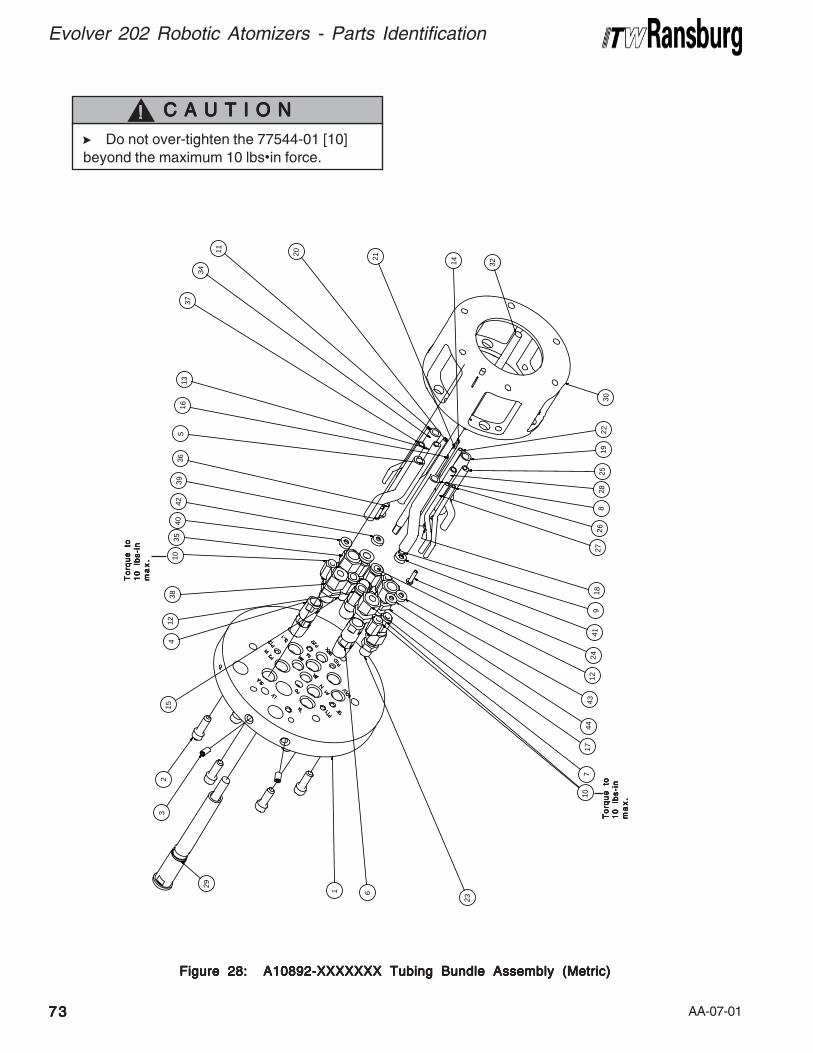
AA-07-01
Evolver 202 Robotic Atomizers - Parts Identification
7373737373
710
241
74
44
34
19
258
193
02
2
11
16
21
14 32
41
238
10
3940
4236
37
32
15
29
1 6
23
35
34
26
5
12
18
13
2728
20
Figure 28: A10892-XXXXXXX Tubing Bundle Assembly (Metric)Figure 28: A10892-XXXXXXX Tubing Bundle Assembly (Metric)Figure 28: A10892-XXXXXXX Tubing Bundle Assembly (Metric)Figure 28: A10892-XXXXXXX Tubing Bundle Assembly (Metric)Figure 28: A10892-XXXXXXX Tubing Bundle Assembly (Metric)
> Do not over-tighten the 77544-01 [10]
beyond the maximum 10 lbs•in force.
C A U T I O NC A U T I O NC A U T I O NC A U T I O NC A U T I O N!!!!!
To
rqu
e
toT
orq
ue
to
To
rqu
e
toT
orq
ue
to
To
rqu
e
to
10
lb
s-i
n1
0
lbs
-in
10
lb
s-i
n1
0
lbs
-in
10
lb
s-i
n
ma
x.
ma
x.
ma
x.
ma
x.
ma
x.
To
rqu
e
toT
orq
ue
to
To
rqu
e
toT
orq
ue
to
To
rqu
e
to
10
lb
s-i
n1
0
lbs
-in
10
lb
s-i
n1
0
lbs
-in
10
lb
s-i
n
ma
x.
ma
x.
ma
x.
ma
x.
ma
x.
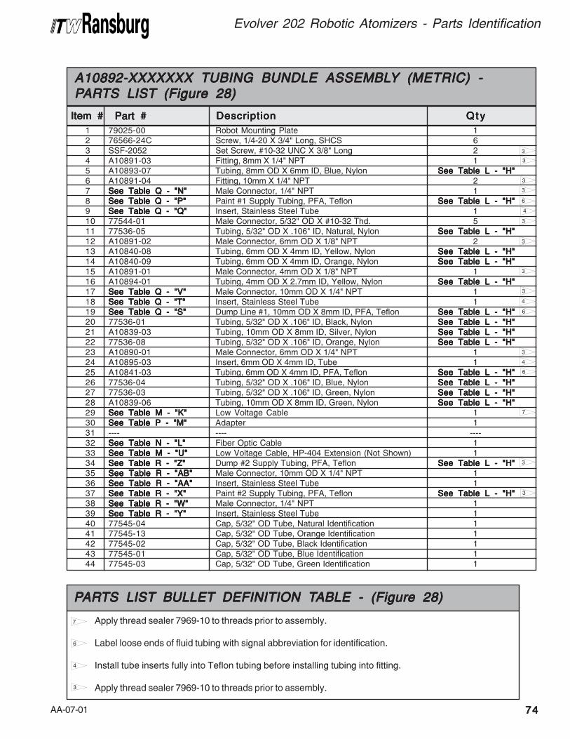
AA-07-01 7474747474
Evolver 202 Robotic Atomizers - Parts Identification
3
4
4
4
3
3
1 79025-00 Robot Mounting Plate 12 76566-24C Screw, 1/4-20 X 3/4" Long, SHCS 63 SSF-2052 Set Screw, #10-32 UNC X 3/8" Long 24 A10891-03 Fitting, 8mm X 1/4" NPT 15 A10893-07 Tubing, 8mm OD X 6mm ID, Blue, Nylon See Table L - "H"See Table L - "H"See Table L - "H"See Table L - "H"See Table L - "H"6 A10891-04 Fitting, 10mm X 1/4" NPT 27 See Table Q - "N"See Table Q - "N"See Table Q - "N"See Table Q - "N"See Table Q - "N" Male Connector, 1/4" NPT 18 See Table Q - "P"See Table Q - "P"See Table Q - "P"See Table Q - "P"See Table Q - "P" Paint #1 Supply Tubing, PFA, Teflon See Table L - "H"See Table L - "H"See Table L - "H"See Table L - "H"See Table L - "H"9 See Table Q - "Q"See Table Q - "Q"See Table Q - "Q"See Table Q - "Q"See Table Q - "Q" Insert, Stainless Steel Tube 110 77544-01 Male Connector, 5/32" OD X #10-32 Thd. 511 77536-05 Tubing, 5/32" OD X .106" ID, Natural, Nylon See Table L - "H"See Table L - "H"See Table L - "H"See Table L - "H"See Table L - "H"12 A10891-02 Male Connector, 6mm OD X 1/8" NPT 213 A10840-08 Tubing, 6mm OD X 4mm ID, Yellow, Nylon See Table L - "H"See Table L - "H"See Table L - "H"See Table L - "H"See Table L - "H"14 A10840-09 Tubing, 6mm OD X 4mm ID, Orange, Nylon See Table L - "H"See Table L - "H"See Table L - "H"See Table L - "H"See Table L - "H"15 A10891-01 Male Connector, 4mm OD X 1/8" NPT 116 A10894-01 Tubing, 4mm OD X 2.7mm ID, Yellow, Nylon See Table L - "H"See Table L - "H"See Table L - "H"See Table L - "H"See Table L - "H"17 See Table Q - "V"See Table Q - "V"See Table Q - "V"See Table Q - "V"See Table Q - "V" Male Connector, 10mm OD X 1/4" NPT 118 See Table Q - "T"See Table Q - "T"See Table Q - "T"See Table Q - "T"See Table Q - "T" Insert, Stainless Steel Tube 119 See Table Q - "S"See Table Q - "S"See Table Q - "S"See Table Q - "S"See Table Q - "S" Dump Line #1, 10mm OD X 8mm ID, PFA, Teflon See Table L - "H"See Table L - "H"See Table L - "H"See Table L - "H"See Table L - "H"20 77536-01 Tubing, 5/32" OD X .106" ID, Black, Nylon See Table L - "H"See Table L - "H"See Table L - "H"See Table L - "H"See Table L - "H"21 A10839-03 Tubing, 10mm OD X 8mm ID, Silver, Nylon See Table L - "H"See Table L - "H"See Table L - "H"See Table L - "H"See Table L - "H"22 77536-08 Tubing, 5/32" OD X .106" ID, Orange, Nylon See Table L - "H"See Table L - "H"See Table L - "H"See Table L - "H"See Table L - "H"23 A10890-01 Male Connector, 6mm OD X 1/4" NPT 124 A10895-03 Insert, 6mm OD X 4mm ID, Tube 125 A10841-03 Tubing, 6mm OD X 4mm ID, PFA, Teflon See Table L - "H"See Table L - "H"See Table L - "H"See Table L - "H"See Table L - "H"26 77536-04 Tubing, 5/32" OD X .106" ID, Blue, Nylon See Table L - "H"See Table L - "H"See Table L - "H"See Table L - "H"See Table L - "H"27 77536-03 Tubing, 5/32" OD X .106" ID, Green, Nylon See Table L - "H"See Table L - "H"See Table L - "H"See Table L - "H"See Table L - "H"28 A10839-06 Tubing, 10mm OD X 8mm ID, Green, Nylon See Table L - "H"See Table L - "H"See Table L - "H"See Table L - "H"See Table L - "H"29 See Table M - "K"See Table M - "K"See Table M - "K"See Table M - "K"See Table M - "K" Low Voltage Cable 130 See Table P - "M"See Table P - "M"See Table P - "M"See Table P - "M"See Table P - "M" Adapter 131 ---- ---- ----32 See Table N - "L"See Table N - "L"See Table N - "L"See Table N - "L"See Table N - "L" Fiber Optic Cable 133 See Table M - "U"See Table M - "U"See Table M - "U"See Table M - "U"See Table M - "U" Low Voltage Cable, HP-404 Extension (Not Shown) 134 See Table R - "Z"See Table R - "Z"See Table R - "Z"See Table R - "Z"See Table R - "Z" Dump #2 Supply Tubing, PFA, Teflon See Table L - "H"See Table L - "H"See Table L - "H"See Table L - "H"See Table L - "H"35 See Table R - "AB"See Table R - "AB"See Table R - "AB"See Table R - "AB"See Table R - "AB" Male Connector, 10mm OD X 1/4" NPT 136 See Table R - "AA"See Table R - "AA"See Table R - "AA"See Table R - "AA"See Table R - "AA" Insert, Stainless Steel Tube 137 See Table R - "X"See Table R - "X"See Table R - "X"See Table R - "X"See Table R - "X" Paint #2 Supply Tubing, PFA, Teflon See Table L - "H"See Table L - "H"See Table L - "H"See Table L - "H"See Table L - "H"38 See Table R - "W"See Table R - "W"See Table R - "W"See Table R - "W"See Table R - "W" Male Connector, 1/4" NPT 139 See Table R - "Y"See Table R - "Y"See Table R - "Y"See Table R - "Y"See Table R - "Y" Insert, Stainless Steel Tube 140 77545-04 Cap, 5/32" OD Tube, Natural Identification 141 77545-13 Cap, 5/32" OD Tube, Orange Identification 142 77545-02 Cap, 5/32" OD Tube, Black Identification 143 77545-01 Cap, 5/32" OD Tube, Blue Identification 144 77545-03 Cap, 5/32" OD Tube, Green Identification 1
Item #Item #Item #Item #Item #
A10892-XXXXXXX TUBING BUNDLE ASSEMBLA10892-XXXXXXX TUBING BUNDLE ASSEMBLA10892-XXXXXXX TUBING BUNDLE ASSEMBLA10892-XXXXXXX TUBING BUNDLE ASSEMBLA10892-XXXXXXX TUBING BUNDLE ASSEMBLYYYYY (METRIC) - (METRIC) - (METRIC) - (METRIC) - (METRIC) -PPPPPARARARARARTS LISTTS LISTTS LISTTS LISTTS LIST (Figure 28) (Figure 28) (Figure 28) (Figure 28) (Figure 28)
Part #Part #Part #Part #Part # DescriptionDescriptionDescriptionDescriptionDescription Q t yQ t yQ t yQ t yQ t y
3
3
3
3
3
6
6
6
3
7
3
3
Apply thread sealer 7969-10 to threads prior to assembly.
Label loose ends of fluid tubing with signal abbreviation for identification.
Install tube inserts fully into Teflon tubing before installing tubing into fitting.
Apply thread sealer 7969-10 to threads prior to assembly.
PPPPPARARARARARTS LISTTS LISTTS LISTTS LISTTS LIST BULLET BULLET BULLET BULLET BULLET DEFINITION T DEFINITION T DEFINITION T DEFINITION T DEFINITION TABLE - (Figure 28)ABLE - (Figure 28)ABLE - (Figure 28)ABLE - (Figure 28)ABLE - (Figure 28)
7
6
4
3
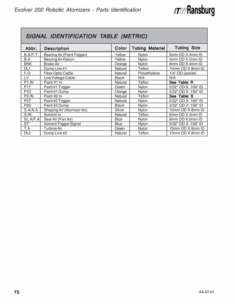
AA-07-01
Evolver 202 Robotic Atomizers - Parts Identification
7575757575
Tubing MaterialTubing MaterialTubing MaterialTubing MaterialTubing Material Tubing SizeTubing SizeTubing SizeTubing SizeTubing Size
B.A/P.T Bearing Air (Paint Trigger) Yellow Nylon 6mm OD X 4mm IDB.A Bearing Air Return Yellow Nylon 4mm OD X 2mm IDBRK Brake Air Orange Nylon 6mm OD X 4mm IDDL1 Dump Line #1 Natural Teflon 10mm OD X 8mm IDF.O Fiber Optic Cable Natural Polyethylene 1/4" OD (jacket)LV Low Voltage Cable Black N/A N/AP1.IN Paint #1 In Natural Teflon See Table RSee Table RSee Table RSee Table RSee Table RP1T Paint #1 Trigger Green Nylon 5/32" OD X .106" IDP1D Paint #1 Dump Orange Nylon 5/32" OD X .106" IDP2.IN Paint #2 In Natural Teflon See Table SSee Table SSee Table SSee Table SSee Table SP2T Paint #2 Trigger Natural Nylon 5/32" OD X .106" IDP2D Paint #2 Dump Black Nylon 5/32" OD X .106" IDS.A/A.A Shaping Air (Atomizer Air) Silver Nylon 10mm OD X 8mm IDS.IN Solvent In Natural Teflon 6mm OD X 4mm IDSL.A/F.A Seal Air (Fan Air) Blue Nylon 8mm OD X 6mm IDST Solvent Trigger Signal Blue Nylon 5/32" OD X .106" IDT.A Turbine Air Green Nylon 10mm OD X 8mm IDDL2 Dump Line #2 Natural Teflon 10mm OD X 8mm ID
SIGNALSIGNALSIGNALSIGNALSIGNAL IDENTIFICA IDENTIFICA IDENTIFICA IDENTIFICA IDENTIFICATION TTION TTION TTION TTION TABLE (METRIC)ABLE (METRIC)ABLE (METRIC)ABLE (METRIC)ABLE (METRIC)
Abbr.Abbr.Abbr.Abbr.Abbr. DescriptionDescriptionDescriptionDescriptionDescription ColorColorColorColorColor
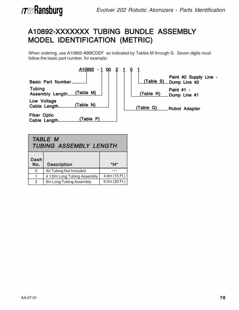
AA-07-01 7676767676
Evolver 202 Robotic Atomizers - Parts Identification
When ordering, use A10892-ABBCDEF as indicated by Tables M through S. Seven digits mustfollow the basic part number, for example:
A10892 - 1 00 2 1 0 1 A10892 - 1 00 2 1 0 1 A10892 - 1 00 2 1 0 1 A10892 - 1 00 2 1 0 1 A10892 - 1 00 2 1 0 1
Low VoltageLow VoltageLow VoltageLow VoltageLow Voltage
Cable LengthCable LengthCable LengthCable LengthCable Length
Basic Part NumberBasic Part NumberBasic Part NumberBasic Part NumberBasic Part Number
Paint #1 -Paint #1 -Paint #1 -Paint #1 -Paint #1 -
Dump Line #1Dump Line #1Dump Line #1Dump Line #1Dump Line #1
Fiber OpticFiber OpticFiber OpticFiber OpticFiber Optic
Cable LengthCable LengthCable LengthCable LengthCable Length
Robot AdapterRobot AdapterRobot AdapterRobot AdapterRobot Adapter(Table N)(Table N)(Table N)(Table N)(Table N)
(Table P)(Table P)(Table P)(Table P)(Table P)
(Table R)(Table R)(Table R)(Table R)(Table R)
(Table Q)(Table Q)(Table Q)(Table Q)(Table Q)
A10892-XXXXXXX TUBING BUNDLE ASSEMBLA10892-XXXXXXX TUBING BUNDLE ASSEMBLA10892-XXXXXXX TUBING BUNDLE ASSEMBLA10892-XXXXXXX TUBING BUNDLE ASSEMBLA10892-XXXXXXX TUBING BUNDLE ASSEMBLYYYYY
MODELMODELMODELMODELMODEL IDENTIFICA IDENTIFICA IDENTIFICA IDENTIFICA IDENTIFICATION (METRIC)TION (METRIC)TION (METRIC)TION (METRIC)TION (METRIC)
Paint #2 Supply Line -Paint #2 Supply Line -Paint #2 Supply Line -Paint #2 Supply Line -Paint #2 Supply Line -
Dump Line #2Dump Line #2Dump Line #2Dump Line #2Dump Line #2(Table S)(Table S)(Table S)(Table S)(Table S)
TubingTubingTubingTubingTubing
Assembly LengthAssembly LengthAssembly LengthAssembly LengthAssembly Length (Table M)(Table M)(Table M)(Table M)(Table M)
Air Tubing Not Included
4 1/2m Long Tubing Assembly
9m Long Tubing Assembly
TTTTTABLE MABLE MABLE MABLE MABLE MTUBING ASSEMBLTUBING ASSEMBLTUBING ASSEMBLTUBING ASSEMBLTUBING ASSEMBLYYYYY LENGTH LENGTH LENGTH LENGTH LENGTH
0
1
2
----
4.6m (15 Ft.)
9.2m (30 Ft.)
DashDashDashDashDashNo.No.No.No.No. "H""H""H""H""H"DescriptionDescriptionDescriptionDescriptionDescription
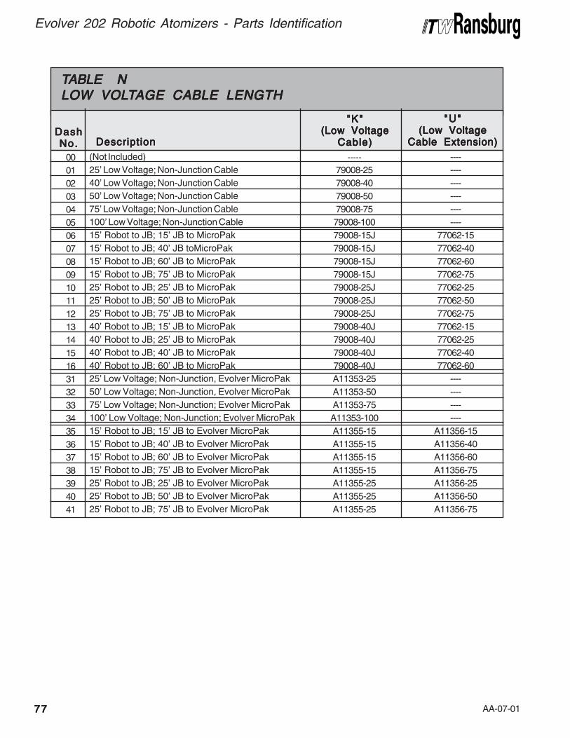
AA-07-01
Evolver 202 Robotic Atomizers - Parts Identification
7777777777
(Not Included)
25' Low Voltage; Non-Junction Cable
40' Low Voltage; Non-Junction Cable
50' Low Voltage; Non-Junction Cable
75' Low Voltage; Non-Junction Cable
100' Low Voltage; Non-Junction Cable
15' Robot to JB; 15' JB to MicroPak
15' Robot to JB; 40' JB toMicroPak
15' Robot to JB; 60' JB to MicroPak
15' Robot to JB; 75' JB to MicroPak
25' Robot to JB; 25' JB to MicroPak
25' Robot to JB; 50' JB to MicroPak
25' Robot to JB; 75' JB to MicroPak
40' Robot to JB; 15' JB to MicroPak
40' Robot to JB; 25' JB to MicroPak
40' Robot to JB; 40' JB to MicroPak
40' Robot to JB; 60' JB to MicroPak
25' Low Voltage; Non-Junction, Evolver MicroPak
50' Low Voltage; Non-Junction, Evolver MicroPak
75' Low Voltage; Non-Junction; Evolver MicroPak
100' Low Voltage; Non-Junction; Evolver MicroPak
15' Robot to JB; 15' JB to Evolver MicroPak
15' Robot to JB; 40' JB to Evolver MicroPak
15' Robot to JB; 60' JB to Evolver MicroPak
15' Robot to JB; 75' JB to Evolver MicroPak
25' Robot to JB; 25' JB to Evolver MicroPak
25' Robot to JB; 50' JB to Evolver MicroPak
25' Robot to JB; 75' JB to Evolver MicroPak
TTTTTABLE NABLE NABLE NABLE NABLE NLOW VOLLOW VOLLOW VOLLOW VOLLOW VOLTTTTTAGE CABLE LENGTHAGE CABLE LENGTHAGE CABLE LENGTHAGE CABLE LENGTHAGE CABLE LENGTH
00
01
02
03
04
05
06
07
08
09
10
11
12
13
14
15
16
31
32
33
34
35
36
37
38
39
40
41
-----
79008-25
79008-40
79008-50
79008-75
79008-100
79008-15J
79008-15J
79008-15J
79008-15J
79008-25J
79008-25J
79008-25J
79008-40J
79008-40J
79008-40J
79008-40J
A11353-25
A11353-50
A11353-75
A11353-100
A11355-15
A11355-15
A11355-15
A11355-15
A11355-25
A11355-25
A11355-25
DashDashDashDashDashNo.No.No.No.No.
"K""K""K""K""K"(Low Voltage(Low Voltage(Low Voltage(Low Voltage(Low Voltage
Cable)Cable)Cable)Cable)Cable)DescriptionDescriptionDescriptionDescriptionDescription
----
----
----
----
----
----
77062-15
77062-40
77062-60
77062-75
77062-25
77062-50
77062-75
77062-15
77062-25
77062-40
77062-60
----
----
----
----
A11356-15
A11356-40
A11356-60
A11356-75
A11356-25
A11356-50
A11356-75
"U""U""U""U""U"(Low Voltage(Low Voltage(Low Voltage(Low Voltage(Low Voltage
Cable Extension)Cable Extension)Cable Extension)Cable Extension)Cable Extension)
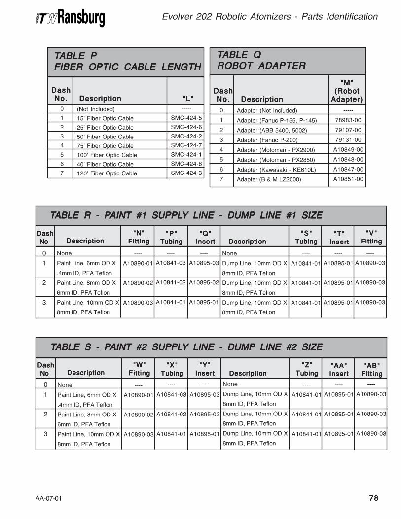
AA-07-01
Adapter (Not Included)
Adapter (Fanuc P-155, P-145)
Adapter (ABB 5400, 5002)
Adapter (Fanuc P-200)
Adapter (Motoman - PX2900)
Adapter (Motoman - PX2850)
Adapter (Kawasaki - KE610L)
Adapter (B & M LZ2000)
TTTTTABLE QABLE QABLE QABLE QABLE QROBOT ADAPTERROBOT ADAPTERROBOT ADAPTERROBOT ADAPTERROBOT ADAPTER
0
1
2
3
4
5
6
7
-----
78983-00
79107-00
79131-00
A10849-00
A10848-00
A10847-00
A10851-00
DashDashDashDashDashNo.No.No.No.No.
"M""M""M""M""M"(Robot(Robot(Robot(Robot(Robot
Adapter)Adapter)Adapter)Adapter)Adapter)DescriptionDescriptionDescriptionDescriptionDescription
(Not Included)
15' Fiber Optic Cable
25' Fiber Optic Cable
50' Fiber Optic Cable
75' Fiber Optic Cable
100' Fiber Optic Cable
40' Fiber Optic Cable
120' Fiber Optic Cable
TTTTTABLE PABLE PABLE PABLE PABLE PFIBER OPTIC CABLE LENGTHFIBER OPTIC CABLE LENGTHFIBER OPTIC CABLE LENGTHFIBER OPTIC CABLE LENGTHFIBER OPTIC CABLE LENGTH
0
1
2
3
4
5
6
7
-----
SMC-424-5
SMC-424-6
SMC-424-2
SMC-424-7
SMC-424-1
SMC-424-8
SMC-424-3
DashDashDashDashDashNo.No.No.No.No. "L""L""L""L""L"DescriptionDescriptionDescriptionDescriptionDescription
7878787878
Evolver 202 Robotic Atomizers - Parts Identification
None
Paint Line, 6mm OD X
.4mm ID, PFA Teflon
Paint Line, 8mm OD X
6mm ID, PFA Teflon
Paint Line, 10mm OD X
8mm ID, PFA Teflon
TTTTTABLE R - PABLE R - PABLE R - PABLE R - PABLE R - PAINTAINTAINTAINTAINT #1 SUPPL #1 SUPPL #1 SUPPL #1 SUPPL #1 SUPPLYYYYY LINE - DUMP LINE - DUMP LINE - DUMP LINE - DUMP LINE - DUMP LINE #1 SIZE LINE #1 SIZE LINE #1 SIZE LINE #1 SIZE LINE #1 SIZE
0
1
2
3
DashDashDashDashDash
No No No No No DescriptionDescriptionDescriptionDescriptionDescription
----
A10890-01
A10890-02
A10890-03
"N""N""N""N""N"
Fitt ingFitt ingFitt ingFitt ingFitt ing
----
A10841-03
A10841-02
A10841-01
"P ""P ""P ""P ""P "
TubingTubingTubingTubingTubing
----
A10895-03
A10895-02
A10895-01
"Q""Q""Q""Q""Q"
InsertInsertInsertInsertInsert
None
Dump Line, 10mm OD X
8mm ID, PFA Teflon
Dump Line, 10mm OD X
8mm ID, PFA Teflon
Dump Line, 10mm OD X
8mm ID, PFA Teflon
DescriptionDescriptionDescriptionDescriptionDescription
----
A10841-01
A10841-01
A10841-01
"S ""S ""S ""S ""S "
TubingTubingTubingTubingTubing
----
A10895-01
A10895-01
A10895-01
"T""T""T""T""T"
InsertInsertInsertInsertInsert
----
A10890-03
A10890-03
A10890-03
"V ""V ""V ""V ""V "
Fitt ingFitt ingFitt ingFitt ingFitt ing
None
Paint Line, 6mm OD X
.4mm ID, PFA Teflon
Paint Line, 8mm OD X
6mm ID, PFA Teflon
Paint Line, 10mm OD X
8mm ID, PFA Teflon
TTTTTABLE S - PABLE S - PABLE S - PABLE S - PABLE S - PAINTAINTAINTAINTAINT #2 SUPPL #2 SUPPL #2 SUPPL #2 SUPPL #2 SUPPLYYYYY LINE - DUMP LINE - DUMP LINE - DUMP LINE - DUMP LINE - DUMP LINE #2 SIZE LINE #2 SIZE LINE #2 SIZE LINE #2 SIZE LINE #2 SIZE
0
1
2
3
DashDashDashDashDash
No No No No No DescriptionDescriptionDescriptionDescriptionDescription
----
A10890-01
A10890-02
A10890-03
"W""W""W""W""W"
Fitt ingFitt ingFitt ingFitt ingFitt ing
----
A10841-03
A10841-02
A10841-01
"X ""X ""X ""X ""X "
TubingTubingTubingTubingTubing
----
A10895-03
A10895-02
A10895-01
"Y ""Y ""Y ""Y ""Y "
InsertInsertInsertInsertInsert
None
Dump Line, 10mm OD X
8mm ID, PFA Teflon
Dump Line, 10mm OD X
8mm ID, PFA Teflon
Dump Line, 10mm OD X
8mm ID, PFA Teflon
DescriptionDescriptionDescriptionDescriptionDescription
----
A10841-01
A10841-01
A10841-01
"Z""Z""Z""Z""Z"
TubingTubingTubingTubingTubing
----
A10895-01
A10895-01
A10895-01
"AA""AA""AA""AA""AA"
InsertInsertInsertInsertInsert
----
A10890-03
A10890-03
A10890-03
"AB""AB""AB""AB""AB"
Fitt ingFitt ingFitt ingFitt ingFitt ing
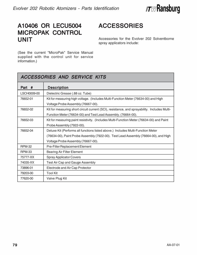
AA-07-017979797979
Evolver 202 Robotic Atomizers - Parts Identification
A10406 OR LECU5004A10406 OR LECU5004A10406 OR LECU5004A10406 OR LECU5004A10406 OR LECU5004
MICROPMICROPMICROPMICROPMICROPAK CONTROLAK CONTROLAK CONTROLAK CONTROLAK CONTROL
UNITUNITUNITUNITUNIT
(See the current "MicroPak" Service Manualsupplied with the control unit for serviceinformation.)
ACCESSORIESACCESSORIESACCESSORIESACCESSORIESACCESSORIES
Accessories for the Evolver 202 Solventbornespray applicators include:
Dielectric Grease (.88 oz. Tube)
Kit for measuring high voltage. (Includes Multi-Function Meter (76634-00) and High
Voltage Probe Assembly (76667-00).
Kit for measuring short circuit current (SCI), resistance, and sprayability. Includes Multi-
Function Meter (76634-00) and Test Lead Assembly. (76664-00).
Kit for measuring paint resistivity. (Includes Multi-Function Meter (76634-00) and Paint
Probe Assembly (7922-00).
Deluxe Kit (Performs all functions listed above.) Includes Multi-Function Meter
(76634-00), Paint Probe Assembly (7922-00). Test Lead Assembly (76664-00), and High
Voltage Probe Assembly (76667-00).
Pre-Filter Replacement Element
Bearing Air Filter Element
Spray Applicator Covers
Test Air Cap and Gauge Assembly
Electrode and Air Cap Protector
Tool Kit
Valve Plug Kit
ACCESSORIES AND SERVICE KITSACCESSORIES AND SERVICE KITSACCESSORIES AND SERVICE KITSACCESSORIES AND SERVICE KITSACCESSORIES AND SERVICE KITS
LSCH0009-00
76652-01
76652-02
76652-03
76652-04
RPM-32
RPM-33
75777-XX
74035-XX
73896-01
79203-00
77620-00
Part #Part #Part #Part #Part # DescriptionDescriptionDescriptionDescriptionDescription
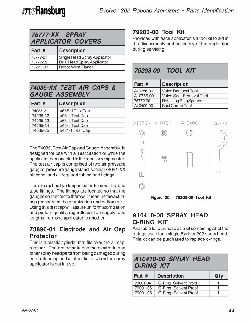
AA-07-01 8080808080
Evolver 202 Robotic Atomizers - Parts Identification
75777-01 Single Head Spray Applicator75777-02 Dual Head Spray Applicator75777-03 Robot Wrist Flange
75777-XX SPRA75777-XX SPRA75777-XX SPRA75777-XX SPRA75777-XX SPRAYYYYYAPPLICAAPPLICAAPPLICAAPPLICAAPPLICATTTTTOR COVERSOR COVERSOR COVERSOR COVERSOR COVERS
Part #Part #Part #Part #Part # DescriptionDescriptionDescriptionDescriptionDescription
The 74035, Test Air Cap and Gauge Assembly, isdesigned for use with a Test Station or while theapplicator is connected to the robot or reciprocator.The test air cap is comprised of two air pressuregauges, pressure gauge stand, special 74061-XXair caps, and all required tubing and fittings.
The air cap has two tapped holes for small barbedtube fittings. The fittings are located so that thegauges connected to them will measure the actualcap pressure of the atomization and pattern air.Using this test cap will assure uniform atomizationand pattern quality, regardless of air supply tubelengths from one applicator to another.
73896-01 Electrode and Air Cap73896-01 Electrode and Air Cap73896-01 Electrode and Air Cap73896-01 Electrode and Air Cap73896-01 Electrode and Air Cap
ProtectorProtectorProtectorProtectorProtectorThis is a plastic cylinder that fits over the air capretainer. The protector keeps the electrode andother spray head parts from being damaged duringbooth cleaning and at other times when the sprayapplicator is not in use.
Figure 29: 79203-00 Tool KitFigure 29: 79203-00 Tool KitFigure 29: 79203-00 Tool KitFigure 29: 79203-00 Tool KitFigure 29: 79203-00 Tool Kit
79203-00 T79203-00 T79203-00 T79203-00 T79203-00 Tool Kitool Kitool Kitool Kitool KitProvided with each applicator is a tool kit to aid inthe disassembly and assembly of the applicatorduring servicing.
A10410-00 SPRAA10410-00 SPRAA10410-00 SPRAA10410-00 SPRAA10410-00 SPRAYYYYY HEAD HEAD HEAD HEAD HEAD
O-RING KITO-RING KITO-RING KITO-RING KITO-RING KITAvailable for purchase as a kit containing all of theo-rings used for a single Evolver 202 spray head.This kit can be purchased to replace o-rings.
74035-21 #65R-1 Test Cap74035-22 #98-1 Test Cap74035-23 #63-1 Test Cap74035-24 #48-1 Test Cap74035-25 #481-1 Test Cap
74035-XX TEST AIR CAPS &74035-XX TEST AIR CAPS &74035-XX TEST AIR CAPS &74035-XX TEST AIR CAPS &74035-XX TEST AIR CAPS &GAUGE ASSEMBLGAUGE ASSEMBLGAUGE ASSEMBLGAUGE ASSEMBLGAUGE ASSEMBLYYYYY
Part #Part #Part #Part #Part # DescriptionDescriptionDescriptionDescriptionDescription
A10756-00 Valve Removal ToolA10766-00 Valve Seat Removal Tool76772-00 Retaining Ring SpannerA10400-00 Seal Carrier Tool
79203-0079203-0079203-0079203-0079203-00 TOOL KIT TOOL KIT TOOL KIT TOOL KIT TOOL KIT
Part #Part #Part #Part #Part # DescriptionDescriptionDescriptionDescriptionDescription
79001-04 O-Ring, Solvent Proof 179001-06 O-Ring, Solvent Proof 179001-05 O-Ring, Solvent Proof 1
A10410-00 SPRAA10410-00 SPRAA10410-00 SPRAA10410-00 SPRAA10410-00 SPRAYYYYY HEAD HEAD HEAD HEAD HEADO-RING KITO-RING KITO-RING KITO-RING KITO-RING KIT
Part #Part #Part #Part #Part # DescriptionDescriptionDescriptionDescriptionDescription Q t yQ t yQ t yQ t yQ t y
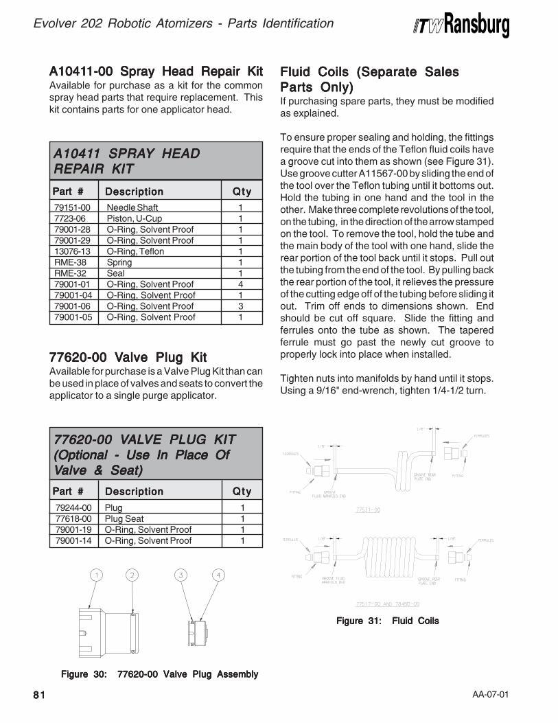
AA-07-018181818181
Evolver 202 Robotic Atomizers - Parts Identification
79151-00 Needle Shaft 17723-06 Piston, U-Cup 179001-28 O-Ring, Solvent Proof 179001-29 O-Ring, Solvent Proof 113076-13 O-Ring, Teflon 1RME-38 Spring 1RME-32 Seal 179001-01 O-Ring, Solvent Proof 479001-04 O-Ring, Solvent Proof 179001-06 O-Ring, Solvent Proof 379001-05 O-Ring, Solvent Proof 1
A1041A1041A1041A1041A10411 SPRA1 SPRA1 SPRA1 SPRA1 SPRAYYYYY HEAD HEAD HEAD HEAD HEADREPREPREPREPREPAIR KITAIR KITAIR KITAIR KITAIR KIT
Part #Part #Part #Part #Part # DescriptionDescriptionDescriptionDescriptionDescription Q t yQ t yQ t yQ t yQ t y
Figure 30: 77620-00 Valve Plug AssemblyFigure 30: 77620-00 Valve Plug AssemblyFigure 30: 77620-00 Valve Plug AssemblyFigure 30: 77620-00 Valve Plug AssemblyFigure 30: 77620-00 Valve Plug Assembly
Fluid Coils (Separate SalesFluid Coils (Separate SalesFluid Coils (Separate SalesFluid Coils (Separate SalesFluid Coils (Separate Sales
Parts Only)Parts Only)Parts Only)Parts Only)Parts Only)If purchasing spare parts, they must be modifiedas explained.
To ensure proper sealing and holding, the fittingsrequire that the ends of the Teflon fluid coils havea groove cut into them as shown (see Figure 31).Use groove cutter A11567-00 by sliding the end ofthe tool over the Teflon tubing until it bottoms out.Hold the tubing in one hand and the tool in theother. Make three complete revolutions of the tool,on the tubing, in the direction of the arrow stampedon the tool. To remove the tool, hold the tube andthe main body of the tool with one hand, slide therear portion of the tool back until it stops. Pull outthe tubing from the end of the tool. By pulling backthe rear portion of the tool, it relieves the pressureof the cutting edge off of the tubing before sliding itout. Trim off ends to dimensions shown. Endshould be cut off square. Slide the fitting andferrules onto the tube as shown. The taperedferrule must go past the newly cut groove toproperly lock into place when installed.
Tighten nuts into manifolds by hand until it stops.Using a 9/16" end-wrench, tighten 1/4-1/2 turn.
Figure 31: Fluid CoilsFigure 31: Fluid CoilsFigure 31: Fluid CoilsFigure 31: Fluid CoilsFigure 31: Fluid Coils
79244-00 Plug 177618-00 Plug Seat 179001-19 O-Ring, Solvent Proof 179001-14 O-Ring, Solvent Proof 1
77620-00 V77620-00 V77620-00 V77620-00 V77620-00 VALALALALALVE PLUG KITVE PLUG KITVE PLUG KITVE PLUG KITVE PLUG KIT(((((Optional - Use In Place OfOptional - Use In Place OfOptional - Use In Place OfOptional - Use In Place OfOptional - Use In Place OfVVVVValve & Seatalve & Seatalve & Seatalve & Seatalve & Seat)))))
Part #Part #Part #Part #Part # DescriptionDescriptionDescriptionDescriptionDescription Q t yQ t yQ t yQ t yQ t y
A1041A1041A1041A1041A10411-00 1-00 1-00 1-00 1-00 Spray Head Repair KitSpray Head Repair KitSpray Head Repair KitSpray Head Repair KitSpray Head Repair KitAvailable for purchase as a kit for the commonspray head parts that require replacement. Thiskit contains parts for one applicator head.
77620-00 V77620-00 V77620-00 V77620-00 V77620-00 Valve Plug Kitalve Plug Kitalve Plug Kitalve Plug Kitalve Plug KitAvailable for purchase is a Valve Plug Kit than canbe used in place of valves and seats to convert theapplicator to a single purge applicator.
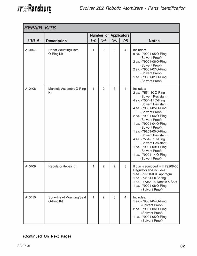
AA-07-01 8282828282
Evolver 202 Robotic Atomizers - Parts Identification
(Continued On Next Page)(Continued On Next Page)(Continued On Next Page)(Continued On Next Page)(Continued On Next Page)
A10407 Robot Mounting Plate 1 2 3 4 Includes:O-Ring Kit 9 ea. - 79001-05 O-Ring
(Solvent Proof)2 ea. - 79001-06 O-Ring
(Solvent Proof)2 ea. - 79001-07 O-Ring
(Solvent Proof)1 ea. - 79001-01 O-Ring
(Solvent Proof)
A10408 Manifold Assembly O-Ring 1 2 3 4 Includes:Kit 2 ea. - 7554-10 O-Ring
(Solvent Resistant)4 ea. - 7554-11 O-Ring
(Solvent Resistant)4 ea. - 79001-05 O-Ring
(Solvent Proof)2 ea. - 79001-06 O-Ring
(Solvent Proof)1 ea. - 79001-04 O-Ring
(Solvent Proof)1 ea. - 79209-00 O-Ring
(Solvent Resistant)4 ea. - 7554-07 O-Ring
(Solvent Resistant)1 ea. - 79001-09 O-Ring
(Solvent Proof)1 ea. - 79001-14 O-Ring
(Solvent Proof)
A10409 Regulator Repair Kit 1 2 2 3 If gun is equipped with 79208-00Regulator and Includes:1 ea. - 79220-00 Diaphragm1 ea. - 74161-00 Spring1 ea. - 77354-00 Needle & Seat1 ea. - 79001-08 O-Ring
(Solvent Proof)
A10410 Spray Head Mounting Seal 1 2 3 4 Includes:O-Ring Kit 1 ea. - 79001-04 O-Ring
(Solvent Proof)2 ea. - 79001-06 O-Ring
(Solvent Proof)1 ea. - 79001-05 O-Ring
(Solvent Proof)
Part #Part #Part #Part #Part #
REPREPREPREPREPAIR KITSAIR KITSAIR KITSAIR KITSAIR KITS
DescriptionDescriptionDescriptionDescriptionDescription 1-2 3-4 5-6 7-81-2 3-4 5-6 7-81-2 3-4 5-6 7-81-2 3-4 5-6 7-81-2 3-4 5-6 7-8 NotesNotesNotesNotesNotes
Number of Applicators Number of Applicators Number of Applicators Number of Applicators Number of Applicators
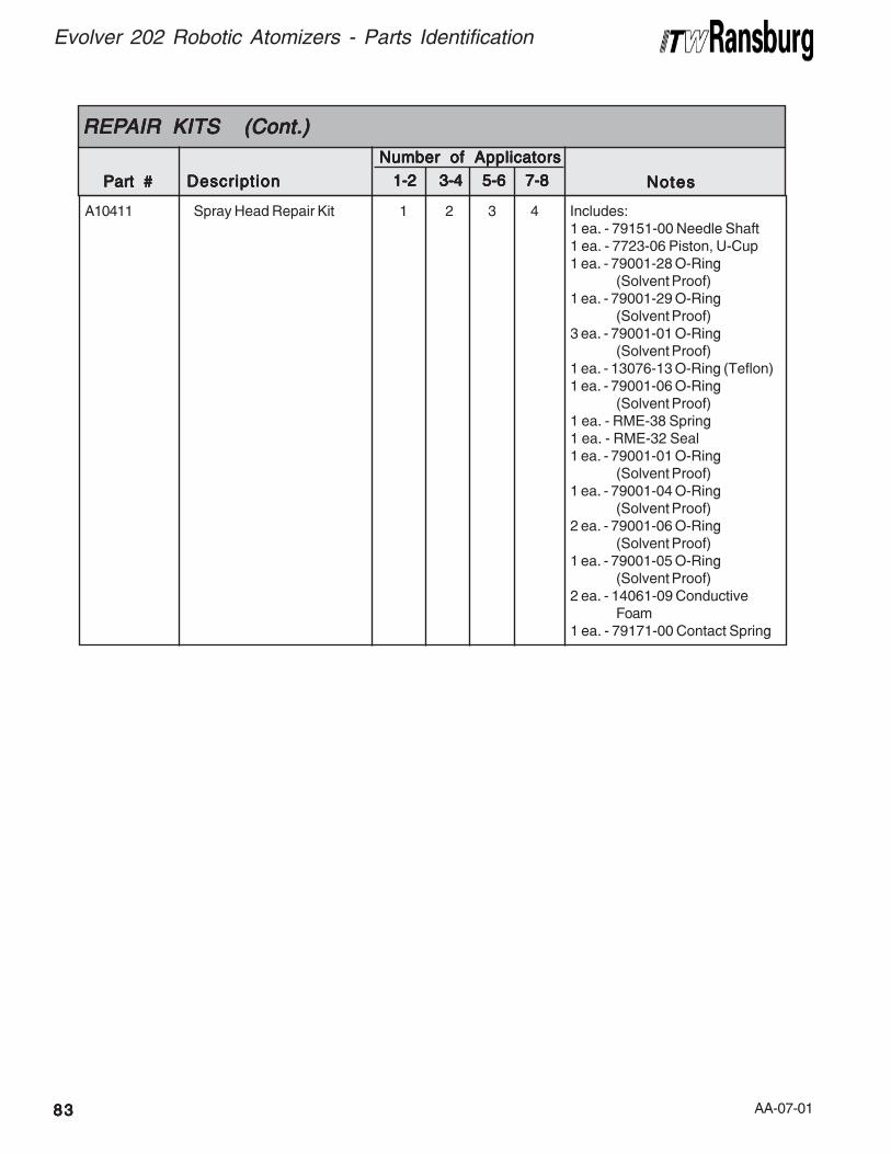
AA-07-018383838383
Evolver 202 Robotic Atomizers - Parts Identification
Part #Part #Part #Part #Part #
REPREPREPREPREPAIR KITS (CAIR KITS (CAIR KITS (CAIR KITS (CAIR KITS (Cont.)ont.)ont.)ont.)ont.)
DescriptionDescriptionDescriptionDescriptionDescription 1-2 1-2 1-2 1-2 1-2 3-4 5-6 7-8 3-4 5-6 7-8 3-4 5-6 7-8 3-4 5-6 7-8 3-4 5-6 7-8 NotesNotesNotesNotesNotes
A10411 Spray Head Repair Kit 1 2 3 4 Includes:1 ea. - 79151-00 Needle Shaft1 ea. - 7723-06 Piston, U-Cup1 ea. - 79001-28 O-Ring
(Solvent Proof)1 ea. - 79001-29 O-Ring
(Solvent Proof)3 ea. - 79001-01 O-Ring
(Solvent Proof)1 ea. - 13076-13 O-Ring (Teflon)1 ea. - 79001-06 O-Ring
(Solvent Proof)1 ea. - RME-38 Spring1 ea. - RME-32 Seal1 ea. - 79001-01 O-Ring
(Solvent Proof)1 ea. - 79001-04 O-Ring
(Solvent Proof)2 ea. - 79001-06 O-Ring
(Solvent Proof)1 ea. - 79001-05 O-Ring
(Solvent Proof)2 ea. - 14061-09 Conductive
Foam1 ea. - 79171-00 Contact Spring
Number of ApplicatorsNumber of ApplicatorsNumber of ApplicatorsNumber of ApplicatorsNumber of Applicators
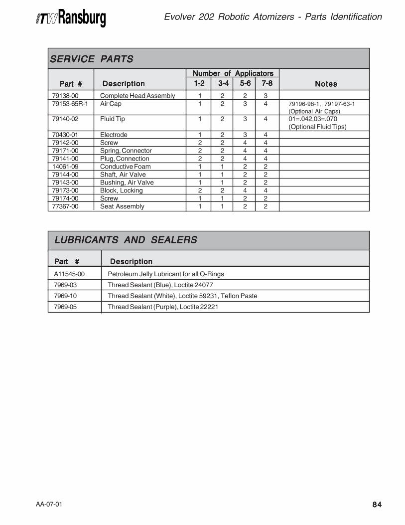
AA-07-01 8484848484
Evolver 202 Robotic Atomizers - Parts Identification
Petroleum Jelly Lubricant for all O-Rings
Thread Sealant (Blue), Loctite 24077
Thread Sealant (White), Loctite 59231, Teflon Paste
Thread Sealant (Purple), Loctite 22221
LUBRICANTS AND SEALERSLUBRICANTS AND SEALERSLUBRICANTS AND SEALERSLUBRICANTS AND SEALERSLUBRICANTS AND SEALERS
A11545-00
7969-03
7969-10
7969-05
Part #Part #Part #Part #Part # DescriptionDescriptionDescriptionDescriptionDescription
79138-00 Complete Head Assembly 1 2 2 379153-65R-1 Air Cap 1 2 3 4 79196-98-1, 79197-63-1
(Optional Air Caps)
79140-02 Fluid Tip 1 2 3 4 01=.042,03=.070(Optional Fluid Tips)
70430-01 Electrode 1 2 3 479142-00 Screw 2 2 4 479171-00 Spring, Connector 2 2 4 479141-00 Plug, Connection 2 2 4 414061-09 Conductive Foam 1 1 2 279144-00 Shaft, Air Valve 1 1 2 279143-00 Bushing, Air Valve 1 1 2 279173-00 Block, Locking 2 2 4 479174-00 Screw 1 1 2 277367-00 Seat Assembly 1 1 2 2
Part #Part #Part #Part #Part #
SERSERSERSERSERVICE PVICE PVICE PVICE PVICE PARARARARARTSTSTSTSTS
DescriptionDescriptionDescriptionDescriptionDescription 1-2 3-4 5-6 7-8 1-2 3-4 5-6 7-8 1-2 3-4 5-6 7-8 1-2 3-4 5-6 7-8 1-2 3-4 5-6 7-8 NotesNotesNotesNotesNotes
Number of Applicators Number of Applicators Number of Applicators Number of Applicators Number of Applicators
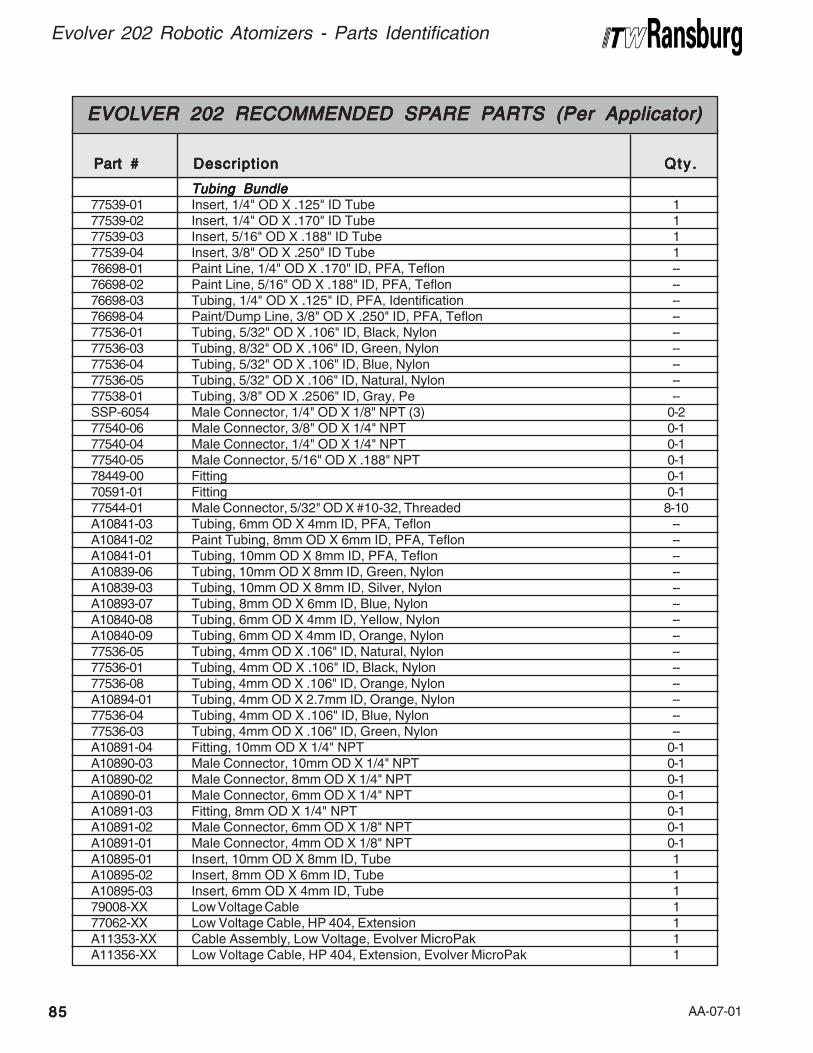
AA-07-01
Evolver 202 Robotic Atomizers - Parts Identification
8585858585
Tubing BundleTubing BundleTubing BundleTubing BundleTubing Bundle77539-01 Insert, 1/4" OD X .125" ID Tube 177539-02 Insert, 1/4" OD X .170" ID Tube 177539-03 Insert, 5/16" OD X .188" ID Tube 177539-04 Insert, 3/8" OD X .250" ID Tube 176698-01 Paint Line, 1/4" OD X .170" ID, PFA, Teflon --76698-02 Paint Line, 5/16" OD X .188" ID, PFA, Teflon --76698-03 Tubing, 1/4" OD X .125" ID, PFA, Identification --76698-04 Paint/Dump Line, 3/8" OD X .250" ID, PFA, Teflon --77536-01 Tubing, 5/32" OD X .106" ID, Black, Nylon --77536-03 Tubing, 8/32" OD X .106" ID, Green, Nylon --77536-04 Tubing, 5/32" OD X .106" ID, Blue, Nylon --77536-05 Tubing, 5/32" OD X .106" ID, Natural, Nylon --77538-01 Tubing, 3/8" OD X .2506" ID, Gray, Pe --SSP-6054 Male Connector, 1/4" OD X 1/8" NPT (3) 0-277540-06 Male Connector, 3/8" OD X 1/4" NPT 0-177540-04 Male Connector, 1/4" OD X 1/4" NPT 0-177540-05 Male Connector, 5/16" OD X .188" NPT 0-178449-00 Fitting 0-170591-01 Fitting 0-177544-01 Male Connector, 5/32" OD X #10-32, Threaded 8-10A10841-03 Tubing, 6mm OD X 4mm ID, PFA, Teflon --A10841-02 Paint Tubing, 8mm OD X 6mm ID, PFA, Teflon --A10841-01 Tubing, 10mm OD X 8mm ID, PFA, Teflon --A10839-06 Tubing, 10mm OD X 8mm ID, Green, Nylon --A10839-03 Tubing, 10mm OD X 8mm ID, Silver, Nylon --A10893-07 Tubing, 8mm OD X 6mm ID, Blue, Nylon --A10840-08 Tubing, 6mm OD X 4mm ID, Yellow, Nylon --A10840-09 Tubing, 6mm OD X 4mm ID, Orange, Nylon --77536-05 Tubing, 4mm OD X .106" ID, Natural, Nylon --77536-01 Tubing, 4mm OD X .106" ID, Black, Nylon --77536-08 Tubing, 4mm OD X .106" ID, Orange, Nylon --A10894-01 Tubing, 4mm OD X 2.7mm ID, Orange, Nylon --77536-04 Tubing, 4mm OD X .106" ID, Blue, Nylon --77536-03 Tubing, 4mm OD X .106" ID, Green, Nylon --A10891-04 Fitting, 10mm OD X 1/4" NPT 0-1A10890-03 Male Connector, 10mm OD X 1/4" NPT 0-1A10890-02 Male Connector, 8mm OD X 1/4" NPT 0-1A10890-01 Male Connector, 6mm OD X 1/4" NPT 0-1A10891-03 Fitting, 8mm OD X 1/4" NPT 0-1A10891-02 Male Connector, 6mm OD X 1/8" NPT 0-1A10891-01 Male Connector, 4mm OD X 1/8" NPT 0-1A10895-01 Insert, 10mm OD X 8mm ID, Tube 1A10895-02 Insert, 8mm OD X 6mm ID, Tube 1A10895-03 Insert, 6mm OD X 4mm ID, Tube 179008-XX Low Voltage Cable 177062-XX Low Voltage Cable, HP 404, Extension 1A11353-XX Cable Assembly, Low Voltage, Evolver MicroPak 1A11356-XX Low Voltage Cable, HP 404, Extension, Evolver MicroPak 1
EVOLEVOLEVOLEVOLEVOLVER 202 RECOMMENDED SPVER 202 RECOMMENDED SPVER 202 RECOMMENDED SPVER 202 RECOMMENDED SPVER 202 RECOMMENDED SPARE PARE PARE PARE PARE PARARARARARTS (Per Applicator)TS (Per Applicator)TS (Per Applicator)TS (Per Applicator)TS (Per Applicator)
Part #Part #Part #Part #Part # DescriptionDescriptionDescriptionDescriptionDescription Qty .Qty .Qty .Qty .Qty .
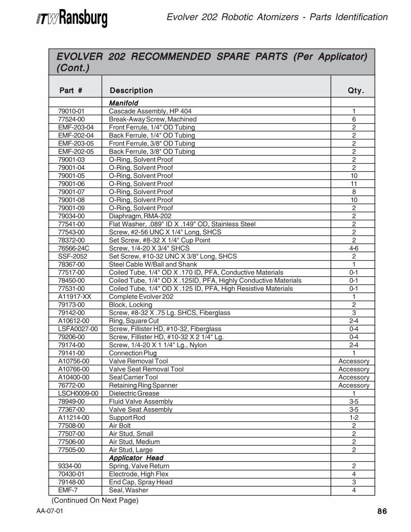
AA-07-01 8686868686
Evolver 202 Robotic Atomizers - Parts Identification
ManifoldManifoldManifoldManifoldManifold79010-01 Cascade Assembly, HP 404 177524-00 Break-Away Screw, Machined 6EMF-203-04 Front Ferrule, 1/4" OD Tubing 2EMF-202-04 Back Ferrule, 1/4" OD Tubing 2EMF-203-05 Front Ferrule, 3/8" OD Tubing 2EMF-202-05 Back Ferrule, 3/8" OD Tubing 279001-03 O-Ring, Solvent Proof 279001-04 O-Ring, Solvent Proof 279001-05 O-Ring, Solvent Proof 1079001-06 O-Ring, Solvent Proof 1179001-07 O-Ring, Solvent Proof 879001-08 O-Ring, Solvent Proof 1079001-09 O-Ring, Solvent Proof 279034-00 Diaphragm, RMA-202 277541-00 Flat Washer, .089" ID X .149" OD, Stainless Steel 277543-00 Screw, #2-56 UNC X 1/4" Long, SHCS 278372-00 Set Screw, #8-32 X 1/4" Cup Point 276566-24C Screw, 1/4-20 X 3/4" SHCS 4-6SSF-2052 Set Screw, #10-32 UNC X 3/8" Long, SHCS 278367-00 Steel Cable W/Ball and Shank 177517-00 Coiled Tube, 1/4" OD X .170 ID, PFA, Conductive Materials 0-178450-00 Coiled Tube, 1/4" OD X .125ID, PFA, Highly Conductive Materials 0-177531-00 Coiled Tube, 1/4" OD X .125 ID, PFA, High Resistive Materials 0-1A11917-XX Complete Evolver 202 179173-00 Block, Locking 279142-00 Screw, #8-32 X .75 Lg. SHCS, Fiberglass 3A10612-00 Ring, Square Cut 2-4LSFA0027-00 Screw, Fillister HD, #10-32, Fiberglass 0-479206-00 Screw, Fillister HD, #10-32 X 2 1/4" Lg. 0-479174-00 Screw, 1/4-20 X 1 1/4" Lg., Nylon 2-479141-00 Connection Plug 1A10756-00 Valve Removal Tool AccessoryA10766-00 Valve Seat Removal Tool AccessoryA10400-00 Seal Carrier Tool Accessory76772-00 Retaining Ring Spanner AccessoryLSCH0009-00 Dielectric Grease 178949-00 Fluid Valve Assembly 3-577367-00 Valve Seat Assembly 3-5A11214-00 Support Rod 1-277508-00 Air Bolt 277507-00 Air Stud, Small 277506-00 Air Stud, Medium 277505-00 Air Stud, Large 2
Applicator HeadApplicator HeadApplicator HeadApplicator HeadApplicator Head9334-00 Spring, Valve Return 270430-01 Electrode, High Flex 479148-00 End Cap, Spray Head 3EMF-7 Seal, Washer 4
EVOLEVOLEVOLEVOLEVOLVER 202 RECOMMENDED SPVER 202 RECOMMENDED SPVER 202 RECOMMENDED SPVER 202 RECOMMENDED SPVER 202 RECOMMENDED SPARE PARE PARE PARE PARE PARARARARARTS (Per Applicator)TS (Per Applicator)TS (Per Applicator)TS (Per Applicator)TS (Per Applicator)(Cont.)(Cont.)(Cont.)(Cont.)(Cont.)
Part #Part #Part #Part #Part # DescriptionDescriptionDescriptionDescriptionDescription Qty .Qty .Qty .Qty .Qty .
(Continued On Next Page)
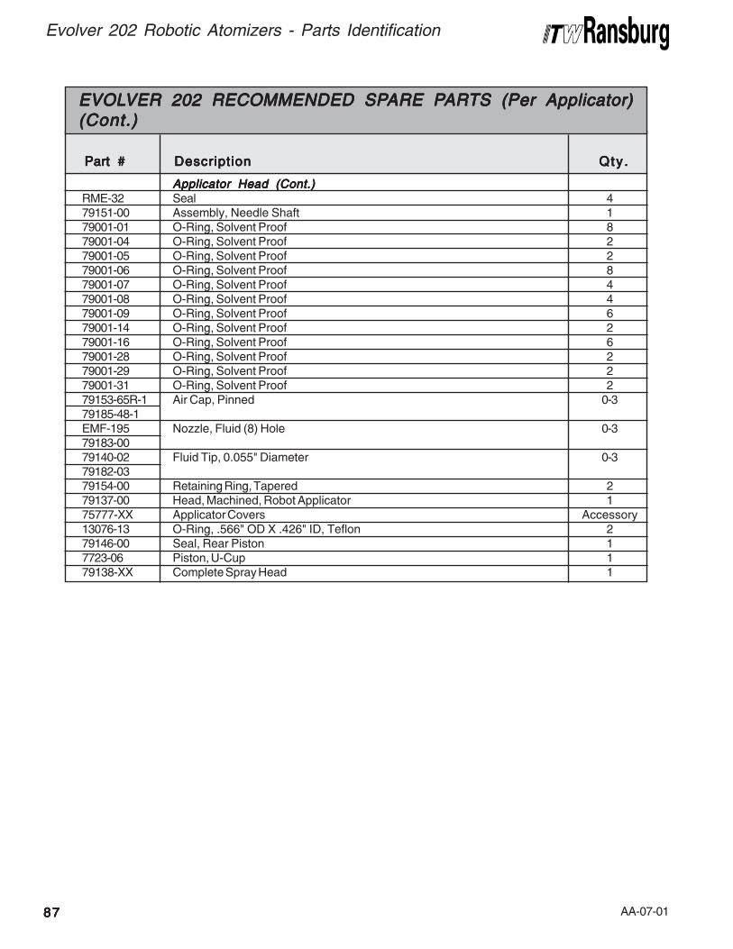
AA-07-01
Evolver 202 Robotic Atomizers - Parts Identification
8787878787
Applicator Head (Cont.)Applicator Head (Cont.)Applicator Head (Cont.)Applicator Head (Cont.)Applicator Head (Cont.)RME-32 Seal 479151-00 Assembly, Needle Shaft 179001-01 O-Ring, Solvent Proof 879001-04 O-Ring, Solvent Proof 279001-05 O-Ring, Solvent Proof 279001-06 O-Ring, Solvent Proof 879001-07 O-Ring, Solvent Proof 479001-08 O-Ring, Solvent Proof 479001-09 O-Ring, Solvent Proof 679001-14 O-Ring, Solvent Proof 279001-16 O-Ring, Solvent Proof 679001-28 O-Ring, Solvent Proof 279001-29 O-Ring, Solvent Proof 279001-31 O-Ring, Solvent Proof 279153-65R-1 Air Cap, Pinned 0-379185-48-1EMF-195 Nozzle, Fluid (8) Hole 0-379183-0079140-02 Fluid Tip, 0.055" Diameter 0-379182-0379154-00 Retaining Ring, Tapered 279137-00 Head, Machined, Robot Applicator 175777-XX Applicator Covers Accessory13076-13 O-Ring, .566" OD X .426" ID, Teflon 279146-00 Seal, Rear Piston 17723-06 Piston, U-Cup 179138-XX Complete Spray Head 1
EVOLEVOLEVOLEVOLEVOLVER 202 RECOMMENDED SPVER 202 RECOMMENDED SPVER 202 RECOMMENDED SPVER 202 RECOMMENDED SPVER 202 RECOMMENDED SPARE PARE PARE PARE PARE PARARARARARTS (Per Applicator)TS (Per Applicator)TS (Per Applicator)TS (Per Applicator)TS (Per Applicator)(Cont.)(Cont.)(Cont.)(Cont.)(Cont.)
Part #Part #Part #Part #Part # DescriptionDescriptionDescriptionDescriptionDescription Qty .Qty .Qty .Qty .Qty .

AA-07-01 8888888888
Evolver 202 Robotic Atomizers - Parts Identification
AA-07-01
Evolver 202 Robotic Atomizers - Warranty Policies
8989898989
WWWWWARRANTYARRANTYARRANTYARRANTYARRANTY POLICIES POLICIES POLICIES POLICIES POLICIES
LIMITED WLIMITED WLIMITED WLIMITED WLIMITED WARRANTYARRANTYARRANTYARRANTYARRANTY
ITW Ransburg will replace or repair without chargeany part and/or equipment that fails within thespecified time (see below) because of faulty work-manship or material, provided that the equipmenthas been used and maintained in accordancewith ITW Ransburg’s written safety and operatinginstructions, and has been used under normaloperating conditions. Normal wear items areexcluded.
THE USE OF OTHER THAN ITW RANSBURGTHE USE OF OTHER THAN ITW RANSBURGTHE USE OF OTHER THAN ITW RANSBURGTHE USE OF OTHER THAN ITW RANSBURGTHE USE OF OTHER THAN ITW RANSBURG
APPROVED PARTS VOIDS ALL WAR-APPROVED PARTS VOIDS ALL WAR-APPROVED PARTS VOIDS ALL WAR-APPROVED PARTS VOIDS ALL WAR-APPROVED PARTS VOIDS ALL WAR-
RANTIES.RANTIES.RANTIES.RANTIES.RANTIES.
SPARE PARTS: One hundred and eighty (180)days from date of purchase, except for rebuiltparts (any part number ending in “R”) for which thewarranty period is ninety (90) days.
EQUIPMENT: When purchased as a completeunit, (i.e., guns, power supplies, control units,etc.), is one (1) year from date of purchase.
WRAPPING THE APPLICATOR IN PLAS-WRAPPING THE APPLICATOR IN PLAS-WRAPPING THE APPLICATOR IN PLAS-WRAPPING THE APPLICATOR IN PLAS-WRAPPING THE APPLICATOR IN PLAS-
TIC WILL VOID THIS WARRANTY.TIC WILL VOID THIS WARRANTY.TIC WILL VOID THIS WARRANTY.TIC WILL VOID THIS WARRANTY.TIC WILL VOID THIS WARRANTY.
ITW RANSBURG’S ONLY OBLIGATION UN-ITW RANSBURG’S ONLY OBLIGATION UN-ITW RANSBURG’S ONLY OBLIGATION UN-ITW RANSBURG’S ONLY OBLIGATION UN-ITW RANSBURG’S ONLY OBLIGATION UN-
DER THIS WARRANTY IS TO REPLACE PARTSDER THIS WARRANTY IS TO REPLACE PARTSDER THIS WARRANTY IS TO REPLACE PARTSDER THIS WARRANTY IS TO REPLACE PARTSDER THIS WARRANTY IS TO REPLACE PARTS
THAT HAVE FAILED BECAUSE OF FAULTYTHAT HAVE FAILED BECAUSE OF FAULTYTHAT HAVE FAILED BECAUSE OF FAULTYTHAT HAVE FAILED BECAUSE OF FAULTYTHAT HAVE FAILED BECAUSE OF FAULTY
WORKMANSHIP OR MATERIALS. THERE AREWORKMANSHIP OR MATERIALS. THERE AREWORKMANSHIP OR MATERIALS. THERE AREWORKMANSHIP OR MATERIALS. THERE AREWORKMANSHIP OR MATERIALS. THERE ARE
NO IMPLIED WARRANTIES NOR WARRAN-NO IMPLIED WARRANTIES NOR WARRAN-NO IMPLIED WARRANTIES NOR WARRAN-NO IMPLIED WARRANTIES NOR WARRAN-NO IMPLIED WARRANTIES NOR WARRAN-
TIES OF EITHER MERCHANTABILITY OR FIT-TIES OF EITHER MERCHANTABILITY OR FIT-TIES OF EITHER MERCHANTABILITY OR FIT-TIES OF EITHER MERCHANTABILITY OR FIT-TIES OF EITHER MERCHANTABILITY OR FIT-
NESS FOR A PARTICULAR PURPOSE. ITWNESS FOR A PARTICULAR PURPOSE. ITWNESS FOR A PARTICULAR PURPOSE. ITWNESS FOR A PARTICULAR PURPOSE. ITWNESS FOR A PARTICULAR PURPOSE. ITW
RANSBURG ASSUMES NO LIABILITY FOR IN-RANSBURG ASSUMES NO LIABILITY FOR IN-RANSBURG ASSUMES NO LIABILITY FOR IN-RANSBURG ASSUMES NO LIABILITY FOR IN-RANSBURG ASSUMES NO LIABILITY FOR IN-
JURY, DAMAGE TO PROPERTY OR FOR CON-JURY, DAMAGE TO PROPERTY OR FOR CON-JURY, DAMAGE TO PROPERTY OR FOR CON-JURY, DAMAGE TO PROPERTY OR FOR CON-JURY, DAMAGE TO PROPERTY OR FOR CON-
SEQUENTIAL DAMAGES FOR LOSS OFSEQUENTIAL DAMAGES FOR LOSS OFSEQUENTIAL DAMAGES FOR LOSS OFSEQUENTIAL DAMAGES FOR LOSS OFSEQUENTIAL DAMAGES FOR LOSS OF
GOODWILL OR PRODUCTION OR INCOME,GOODWILL OR PRODUCTION OR INCOME,GOODWILL OR PRODUCTION OR INCOME,GOODWILL OR PRODUCTION OR INCOME,GOODWILL OR PRODUCTION OR INCOME,
WHICH RESULT FROM USE OR MISUSE OFWHICH RESULT FROM USE OR MISUSE OFWHICH RESULT FROM USE OR MISUSE OFWHICH RESULT FROM USE OR MISUSE OFWHICH RESULT FROM USE OR MISUSE OF
THE EQUIPMENT BY PURCHASER OR OTH-THE EQUIPMENT BY PURCHASER OR OTH-THE EQUIPMENT BY PURCHASER OR OTH-THE EQUIPMENT BY PURCHASER OR OTH-THE EQUIPMENT BY PURCHASER OR OTH-
ERS.ERS.ERS.ERS.ERS.
EXCLUSIONS:EXCLUSIONS:EXCLUSIONS:EXCLUSIONS:EXCLUSIONS:If, in ITW Ransburg’s opinion the warranty item inquestion, or other items damaged by this part wasimproperly installed, operated or maintained,Ransburg will assume no responsibility for repairor replacement of the item or items. The pur-chaser, therefore will assume all responsibility forany cost of repair or replacement and servicerelated costs if applicable.

AA-07-01
Form No. AH-07-01Litho in U.S.A.06/07
ManufacturingManufacturingManufacturingManufacturingManufacturing1910 North Wayne StreetAngola, Indiana 46703-9100Telephone: 260/665-8800Fax: 260/665-8516
TTTTTechnical/Service Assistanceechnical/Service Assistanceechnical/Service Assistanceechnical/Service Assistanceechnical/Service AssistanceAutomotive Assembly and Tier I Telephone: 800/ 626-3565 Fax: 419/ 470-2040Industrial Systems Telephone: 800/ 233-3366 Fax: 419/ 470-2071Ransburg Guns Telephone: 800/ 233-3366 Fax: 419/ 470-2071www.itwransburg.com
TTTTTechnical Support Representative will direct you to the appropriate telephoneechnical Support Representative will direct you to the appropriate telephoneechnical Support Representative will direct you to the appropriate telephoneechnical Support Representative will direct you to the appropriate telephoneechnical Support Representative will direct you to the appropriate telephone
number for ordering Spare Parts.number for ordering Spare Parts.number for ordering Spare Parts.number for ordering Spare Parts.number for ordering Spare Parts.
© 2007 Illinois Tool Works Inc. All rights reserved.Models and specifications subject to change without notice.
Service Manual Price: Service Manual Price: Service Manual Price: Service Manual Price: Service Manual Price: €40.00 (Euro)40.00 (Euro)40.00 (Euro)40.00 (Euro)40.00 (Euro)
$50.00 (U.S.)$50.00 (U.S.)$50.00 (U.S.)$50.00 (U.S.)$50.00 (U.S.)