aa f2c-c 2009 07 catalogo eng - homberger s.p.a.€¦ · 4 3. nomenclature 4. products 5. speed...
TRANSCRIPT

No. F2003E-1

1. Construction..................................................................................1
2. Application Examples .........................................................3
3. Nomenclature ..............................................................................4
4. Products .............................................................................................4
5. Speed Ratio & Rotation Direction .........................4
6. Operating Principles ............................................................5
7. Rating ....................................................................................................6
8. Engineering Data .....................................................................8
9. Main Bearings .......................................................................... 11
10. Selection ........................................................................................ 12
11. Nortice for Designing ..................................................... 14
12. Outline Drawing.................................................................... 16
Warranty Standard

2

3
2. Application Examples
1. ConstructionFig. C-1

4
3. Nomenclature
4. Products
5. Speed Ratio & Rotation Direction
F 2C SF — C35 — — 119
Reduction ratio
Frame size
Standard: −
Special specification: S
Shape of Ring gear housing Farm of a cylinder : −
With flange : F
2C(Output shaft with angular contact ball bearing)
Symbol of Fine CYCLO
Specification suffix
Frame sizeReduction ratio
59 89 119
C25
C35
C45
C55
C65
Mark : Model Lineup
High Speed Shaft
Ring Gear Housing
Slow Speed Shaft
Reducer
Input : High SpeedShaft
Output : Slow SpeedShaft
Fixed : Ring GearHousing
i = -1/n
Increaser
Input : Ring GearHousing
Output : High SpeedShaft
Fixed : Slow SpeedShaft
i = n+1
Increaser
Input : Ring GearHousing
Output : Slow SpeedShaft
Fixed : High SpeedShaft
i = (n+1)/n
Reducer
Input : High SpeedShaft
Output : Ring GearHousing
Fixed : Slow SpeedShaft
i = 1/(n+1)
Reducer
Input : Slow SpeedShaft
Output : Ring GearHousing
Fixed : High SpeedShaft
i = n/(n+1)
Reducer
Input : Slow SpeedShaft
Output : High SpeedShaft
Fixed : Ring GearHousing
i = -n
When all elements
rotate at the same
time, speed ratio is
based on a
combination out of 1
throught 6."
Speed ratio = (Output
Speed/Input Speed)
("-" indicates opposite
direction.)
Reduction ratio
Fig. C-2
1
5
2
6
3
7
4

5
6. Operating PrinciplesThe reducer portion of the FINE CYCLO® is fundamentaly different in principle and mechanism from the involute gearing mechanism of competitive gearmotors. The unique speed reducer portion is an ingenious combination of the following two mechanisms:
☆ A combination of a planet gear and a fixed internal sun gear. In the FINE CYCLO®, the planet gear has cycloidal-shaped teeth and the sun gear has circular pin teeth. The number of teeth in the planet gear is one or two less than the sun gear.
☆ A constant speed internal gearing mechanism.
2e
Epitrochoid planet gear(P)
Circular tooth fixedinternal sun gear(S)
Crankshaft
Slow speed shaft pin
Planet gear(cycloid disc)
Eccentricity
Twice eccentricity
Eccentricity
Twice eccentricity
Ring gear pin(with roller)
Slow speed shaft pin(with roller)
Cycloid disc
Planet gear(P)
Angular velocity ofcrankshaft
Angular velocity ofplanet gear
Fixed sun gear(S)
Crankshaft axis
Rotation of crankshaft
Rotation of planet gear
Fig. C-3 Principle of internal Planetary Gearing
Fig. C-4 Epitrochoid Planet Gear-Circular(PIN)
Tooth Sun Gear Combination
Fig. C-5 Constant Speed Internal Gearing
Fig. C-6 Combination of Planet-Sun Gears and Constant Speed Internal Gear
See Fig. C-3
In equation 1, below, P identifies the number of the planet gear
teeth, S that of the sun gear, w2 the angular velocity of the planet
gear around its own axis. The velocity ratio of w2 to w1 is shown
as follows:
With S greater by one or two than P in this equation, the highest
velocity ratio is obtainable.
That is, if S-P=1 is applied to Equation 1, the velocity ratio may be
calculated from the following equation:
Or if S-P= 2 is applied to Equation 1, the velocity ratio may be
calculated from the following equation:
As the crankshaft rotates at the angular velocity w1 around the
axis of the sun gear, the planet gear rotates at the angular
velocity:
when P indicates the number of the teeth of the planet gear and
the symbol indicates that the rotation of the planet gear is in a
reverse direction to that of the crankshaft.
In the FINE CYCLO®, illustrated in Fig. C-4, circular teeth(pins) are
adapted for the sun gear and epitrochoid curved teeth for the
planet gear, thereby avoiding tooth top interference. The rotation
of the planet gear around its own axis is taken out through a
constant speed internal gearing mechanism as shown in Fig. C-5.
In this mechanism shown in Fig. C-6, the pins of the slow speed
shaft are evenly spaced on a circle that is concentric to the axis of
the sun gear. The pins transmit the rotation of the planet gear by
rolling internally on the circumference of the bores of each planet
gear or cycloid disc. The diameter of the bores minus the
diameter of the slow speed shaft pins is equal to twice the
eccentricity value of the crank shaft (eccentric). This mechanism
smoothly transmits only the rotation of the planet gear around its
own axis to the slow speed shaft.
w2
w1=1- =- ...Equation 1
S
P
S-P
P
w2
w1= ...Equation 2
1
P
w2
w1= ...Equation 3
2
P
- or - 1w1
P
2w1
P

6
1.70
1.13
0.84
3.24
2.15
1.61
5.27
3.50
2.61
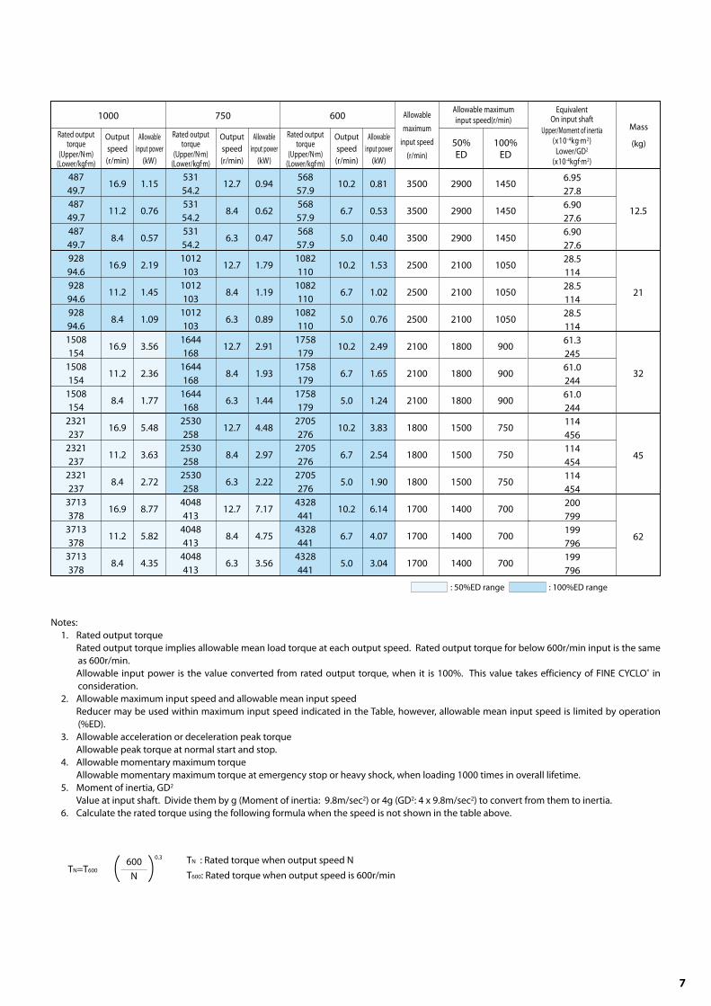
7. Rating
Input speed (r/min)
Reduction
ratio
Rated output torque
(Upper/N m)(Lower/kgf m)
Output
speed
(r/min)
Allowable
input power
(kW)
Rated output torque
(Upper/N m)(Lower/kgf m)
Output
speed
(r/min)
Allowable
input power
(kW)
Rated output torque
(Upper/N m)(Lower/kgf m)
Output
speed
(r/min)
Allowable
input power
(kW)
Rated output torque
(Upper/N m)(Lower/kgf m)
Output
speed
(r/min)
Allowable
input power
(kW)
2500 2000 1750 1500
Table C-1 Rating Table (Input rotation base)
Model
F2C
F2CF
F2CF
F2CF
F2CF
370
37.7
370
37.7
370
37.7
42.4
28.1
21.0
2.19
1.45
1.08
396
40.4
396
40.4
396
40.4
754
76.9
754
76.9
754
76.9
59
89
119
59
89
119
59
89
119
59
89
119
59
89
119
33.9
22.5
16.8
33.9
22.5
16.8
1.87
1.24
0.93
3.56
2.36
1.77
412
42
412
42
412
42
785
80
785
80
785
80
1275
130
1275
130
1275
130
29.7
19.7
14.7
29.7
19.7
14.7
29.7
19.7
14.7
Frame size
C25
C35
C45
C55
C65
432
44.0
432
44.0
432
44.0
822
83.8
822
83.8
822
83.8
1336
136
1336
136
1336
136
2055
209
2055
209
2055
209
25.4
16.9
12.6
25.4
16.9
12.6
25.4
16.9
12.6
25.4
16.9
12.6
1.53
1.01
0.76
2.91
1.93
1.44
4.73
3.14
2.35
7.28
4.83
3.61
Frame
size
Maximum acceleration
or deceleration torque
Peak torque for
emergency stop
(N m) (kgf m) (N m) (kgf m)
Table C-2 Maximum acceleration or deceleration torque
C25
C35
C45
C55
C65
1030
1962
3188
4316
6278
105
200
325
440
640
2060
3924
6377
8633
12577
210
400
650
880
1280
7
Rated output torque
(Upper/N m)(Lower/kgf m)
Output
speed
(r/min)
Allowable
input power
(kW)
Rated output torque
(Upper/N m)(Lower/kgf m)
Output
speed
(r/min)
Allowable
input power
(kW)
Rated output torque
(Upper/N m)(Lower/kgf m)
Output
speed
(r/min)
Allowable
input power
(kW)
1000 750 600Allowable maximum
input speed(r/min)
50%ED
100%ED
Equivalent On input shaft
Upper/Moment of inertia(x10 -4kg m2)
Lower/GD2
(x10-4kgf m2)
Allowable
maximum
input speed
(r/min)
487
49.7
487
49.7
487
49.7
928
94.6
928
94.6
928
94.6
1508
154
1508
154
1508
154
2321
237
2321
237
2321
237
3713
378
3713
378
3713
378
16.9
11.2
8.4
16.9
11.2
8.4
16.9
11.2
8.4
16.9
11.2
8.4
16.9
11.2
8.4
1.15
0.76
0.57
2.19
1.45
1.09
3.56
2.36
1.77
5.48
3.63
2.72
8.77
5.82
4.35
531
54.2
531
54.2
531
54.2
1012
103
1012
103
1012
103
1644
168
1644
168
1644
168
2530
258
2530
258
2530
258
4048
413
4048
413
4048
413
12.7
8.4
6.3
12.7
8.4
6.3
12.7
8.4
6.3
12.7
8.4
6.3
12.7
8.4
6.3
0.94
0.62
0.47
1.79
1.19
0.89
2.91
1.93
1.44
4.48
2.97
2.22
7.17
4.75
3.56
568
57.9
568
57.9
568
57.9
1082
110
1082
110
1082
110
1758
179
1758
179
1758
179
2705
276
2705
276
2705
276
4328
441
4328
441
4328
441
10.2
6.7
5.0
10.2
6.7
5.0
10.2
6.7
5.0
10.2
6.7
5.0
10.2
6.7
5.0
0.81
0.53
0.40
1.53
1.02
0.76
2.49
1.65
1.24
3.83
2.54
1.90
6.14
4.07
3.04
Mass
(kg)
6.95
27.8
6.90
27.6
6.90
27.6
28.5
114
28.5
114
28.5
114
61.3
245
61.0
244
61.0
244
114
456
114
454
114
454
200
799
199
796
199
796
12.5
21
45
32
62
3500
3500
3500
2500
2500
2500
2100
2100
2100
1800
1800
1800
1700
1700
1700
1450
1450
1450
1050
1050
1050
900
900
900
750
750
750
700
700
700
2900
2900
2900
2100
2100
2100
1800
1800
1800
1500
1500
1500
1400
1400
1400
: 50%ED range : 10 0%ED range
Notes:
1. Rated output torque
Rated output torque implies allowable mean load torque at each output speed. Rated output torque for below 600r/min input is the same
as 600r/min.
Allowable input power is the value converted from rated output torque, when it is 100%. This value takes efficiency of FINE CYCLO® in
consideration.
2. Allowable maximum input speed and allowable mean input speed
Reducer may be used within maximum input speed indicated in the Table, however, allowable mean input speed is limited by operation
(%ED).
3. Allowable acceleration or deceleration peak torque
Allowable peak torque at normal start and stop.
4. Allowable momentary maximum torque
Allowable momentary maximum torque at emergency stop or heavy shock, when loading 1000 times in overall lifetime.
5. Moment of inertia, GD2
Value at input shaft. Divide them by g (Moment of inertia: 9.8m/sec2) or 4g (GD2: 4 x 9.8m/sec2) to convert from them to inertia.
6. Calculate the rated torque using the following formula when the speed is not shown in the table above.
TN : Rated torque when output speed N
T600: Rated torque when output speed is 600r/min
600
N
0.3
TN=T600

8
Fig. C-7 Hysteresis curve
Fig. C-8
Table C-3 Engineering data
Frame
size
C25
C35
C45
C55
C65
412
42
785
80
1275
130
1962
200
3139
320
12.4
1.26
23.5
2.40
38.3
3.90
58.9
6.00
94.2
9.60
128
13
294
30
491
50
687
70
1030
105
1.0
Rated output torque
1750r/minUp/ N m
Down/ kgf m
Lost Motion
Measured torque
Up/ N mDown/ kgf m
Lost Motion
arc min
StiffnessUp :
N m/arc minDown :
kgf m/arc min
8-2. No Load Running Torque
No load running torque indicates torque on input shaft for rotating reducer under no-load condition.
Notes) 1. Fig. C-8 shows average data after
reducers have been run.
2. Measurement Conditions
8. Engineering Data
8-1. Stiffness and lost motion
output flange (rotational angle) when load is removed slowly from allowable torque to zero torque, with fixed input shaft.
± 3% of allowable output torque.
when allowable torque is 50% and 100% on the hysteresis curve.
(Example calculation of torsional deflected angle)
Calculation of torsion angle when torque is applied in one direction using C35 as example.
1) When load torque is 15N m
(When load torque is in the range of lost motion)
2) When load torque is 600N m
Note) Arc min means "minute" of the angle.Stiffness is the
average value (typical data).
! = x =0.32 arcmin
! = x =2.5 arcmin
1
2
1
2
15
23.5
600−23.5
294
Ring gear housing temperature
Accuracy in assembled dimensions
Lubrication
Approx. 30°C
Refer to 11.1
Standard grease

9
8-3. No-Load Friction Torque on Output Shaft
Indicates torque necessary to start rotation from output side of reducer from stop without load.
8-4. Efficiency
Notes: 1. Table C-4 shows average data after reducers have been run.
2. Measurement Conditions
Table C-4 Value of no-load friction torque on output shaft
Fig. C-9 Efficiency Curve (Frame size C25-C45)
40
50
60
70
80
90
100
0 500 1000 1500 2000 2500
Input speed r/min
Eff
icie
ncy
%
Fig. C-10 (Frame size C55-C65)
40
50
60
70
80
90
100
0 500 1000 1500 2000 2500
Input speed r/min
Eff
icie
ncy
%
Efficiency varies by input speed, load torque, grease
temperature, reduction ratio, etc.
Fig. C-9 and C-10 indicates efficiency vs. input speed at
allowable output torque with stable grease temperature.
Efficiency curve is indicated with flexible coverage for
variations in models and reduction ratio.
Fig. C-11 Compensation Curve of Efficiency
1.0
0.9
0.80 0.5 1.0
(Load torque/Rated output torque at 1750 r/min)
Co
mp
ensatio
n f
acto
r fo
r eff
icie
ncy
Torque ratio
Compensation efficiency=Efficiency(Fig.C-9, Fig. C-10) x
Compensation factor for efficiency(Fig.C-11)
Note) 1. Efficiency varies when load torque differs with
allowable torque. Check the compensation factor in
the left diagram.
2. When torque ratio is over 1.0, compensation factor for
efficiency is 1.0.
Accuracy in assembled dimensions
Lubrication
Refer Item 11-1
Standard grease
Frame
size N m kgf m
C25
C35
C45
C55
C65
59
118
147
245
343
6
12
15
25
35
No-load friction torque on output shaft

10
L(mm)
Frame size
C25 C35 C45 C55 C65
Frame size 2500 2000 1750 1500 1000 750
Input speed r/min
8-5. ALLOWABLE RADIAL LOAD & AXIAL LOAD OF HIGH SPEED SHAFT
When a gear or sheave is mounted on the high speed shaft, radial load and axial load should be equal to or less than allowable value.
Check radial & axial load by following the next formula (1)-(3).
Table C-5 Actual radial load Pro(Up: N/Down: kgf )
Fig. C-12 Load location on input shaft
Table C-6 Actual axial load Pao(Up: N/Down: kgf )
Table C-8 Coupling Factor Cf
Table C-9 Shock Factor FS1
Table C-7 Load Location Factor Lf
5
10
15
20
25
30
35
40
45
50
60
70
80
Lf=When 1
of L(mm)22 30 36 42 44
0.80
0.86
0.92
0.98
1.14
1.36
1.59
1.82
2.05
0.76
0.81
0.86
0.90
0.95
1.00
1.17
1.33
1.50
1.67
2.00
0.75
0.79
0.83
0.87
0.91
0.95
0.99
1.11
1.25
1.39
1.67
1.94
0.73
0.77
0.80
0.84
0.88
0.91
0.95
0.99
1.07
1.19
1.43
1.67
1.90
0.73
0.77
0.80
0.84
0.87
0.90
0.94
0.97
1.02
1.14
1.36
1.59
1.82
C25
C35
C45
C55
C65
563
57
589
60
687
70
785
80
620
63
723
74
826
84
981
100
709
72
828
84
946
96
1123
114
1419
145
781
80
911
93
1041
106
1236
126
1561
159
600
841
86
981
100
1121
114
1332
136
1682
171
Frame size 2500 2000 1750 1500 1000 750
Input speed r/min
C25
C35
C45
C55
C65
540
55
589
60
746
76
628
64
795
81
912
93
677
69
863
88
981
100
1481
151
824
84
1040
106
1197
122
1785
182
2570
262
942
96
1197
122
1373
140
2050
209
2953
301
600
1040
106
1334
136
1530
156
2276
232
3286
335
+ Cf FS1 " 1
(1) Radial load Pr
Pr : Actual radial load [N, kgf ]
T : Equivalent torque on input shaf [N m, kgf m]
R : Pitch circle radius of sprocket, gear, or sheave [m]
Pro : Allowable radial load [N, kgf ] (Table C-5)
Pa : Actual axial load [N, kgf ]
Pao : Allowable axial load [N, kgf ] (Table C-6)
Lf : Load location factor (Table C-7)
Cf : Coupling factor (Table C-8)
FS1 : Shock factor (Table C-9)
(2) Axial load Pa
(3) When radial and axial load co-exist
Pr = " [N, kgf ]
Pa "
[N, kgf ]
(Formula C-1)
(FormulaC-2)
(FormulaC-3)
T
R
Pro
Lf Cf FS1
Pao
Cf FS1
Pr Lf
Pro
Pa
Pao
CfCoupling method
Chain
Machine gear or pinion
Timing belt
V-Belt
1
1.25
1.25
1.5
FS1Degree of shock
Practically no shock
Light shock
Severe shock
1
1-1.2
1.4-1.6

11
Frame size
Span of Loading Points
9. Main Bearings
Fig. C-13 Span between each loading point
Note) Consult us if: Lr > 4 x L1
1. Moment Stiffness
Indicates stiffness on inclination of output shaft with
external moment.
External moment (M)
M = Pr Lr + Pa La ............................................................... (Formula C-4)
2. Allowable Moment & Allowable Axial Load
Check external moment and external axial load with
Formula C-5, Formula C-6, and Fig.C-13.
Equivalent moment (Me)
Me = Cf FS1 Pr Lr + Cf FS1 Pa La .................................. (Formula C-5)
Equivalent axial load (Pae)
Pae = Cf FS1 Pa ..........................................................................................................................(Formula C-6)
Cf : Coupling factor [Table C-13]
FS1: Shock factor [Table C-14]
Table C-13 Coupling Factor Cf
General purpose chain
Machine gear or pinion
Timing belt
V-Belt
Load connection factor Cf
1
1.25
1.25
1.5
Table C-14 Shock factor FS1
Uniform load (no shock)
Moderate shocks
Heavy shocks
Load Classification FS1
1
1-1.2
1.4-1.6
Fig. C-14 Diagram of Allowable Moment & Axial Load
Pr: Actual radial load(N, kgf )
Pa: Actual axial load(N, kgf )
Table C-10 Span of Loading Points(mm)
C25
C35
C45
C55
C65
L1(mm)
102
135.2
158.8
191.8
211.8
a(mm)
13.5
24.6
30.9
41.9
46.4
Table C-11 Moment Stiffness
Frame size
C25
C35
C45
C55
C65
(N m/arcmin)
883
1668
2649
3924
5690
(kgf m/arcmin)
90
170
270
400
580
Moment Stiffness
Table C-12 Allowable Moment & Allowable Axial Load
Frame size
C25
C35
C45
C55
C65
(N m)
1619
2551
3924
6082
8829
(kgf m)
165
260
400
620
900
(N)
5396
6867
8339
10791
13734
(kgf )
550
700
850
1100
1400
Allowable Moment Allowable Axial Load
Equivalent moment Me (N m)
Eq
uiv
ale
nt
axi
al l
oa
d P
ae
(N)
Equivalent moment Me (N m)
Eq
uiv
ale
nt
axi
al l
oa
d P
ae
(N)

12
TE ≦ TOE
≦
≦
≦
≦
≦
( )
≦
NO
NO
NO NO
NO
NO
NO
Evaluate load characteristic
Calculate of average input speed
Calculate of average output torque
(nE)
(TE)
TOE
Calculate of allowable rating output torque at average input speed
Selection Table(Table C-1)
Select larger size or
lower average output torque TE.
Select tentative frame size
Radial load at output shaftAxial load at output shaftMoment
Check
Actual radial load, axial load, or moment
Allowable radial load, axial load, or moment
(Table C-5, Formula C-1)(Table C-12, Formula C-6)
Check input speed
Maximum input speed
Allowable maximum input speed
Calculation of %ED
Allowable average input speed for %ED
Average input speed
Check peak torque acceleration and deceleration
Peak torque at acceleration and deceleration
Allowable peak torque at acceleration and deceleration
Check emergency torque
Emergency torque
Allowable peak torque for emergency stop
(Table C-2)(Table C-1)
(Table C-2)(Table C-3)
Selection of frame size
End
Actual radial load
Allowable radial load
(Table C-5, Formula C-1)
Check radial load at input shaft
10. Selection
10-1. Flow Cart and Formula of Selection
FIG. C-15 Load cycle
nA : Average input speed during
acceleration under
condition defined in Fig.
C-15
nR : Input speed with normal
running
nB : Average input speed during
deceleration in Fig. C-15
nA =
tA : Acceleration time
tR : Normal running time
tB : Deceleration time
tO : Total running time
tP : Standstill time
T : Time/Cycle
TA : Acceleration peak torque
TR : Torque during normal running
TB : Peak torque at braking
nR
2
nB = nR
2

13
FS2Loading condition
Table C-15 FS2 Load factor
Uniform load
Moderate shock
Heavy shock
1
11.2
1.41.6
10-2. Example of Selection
Average input speed nE =
Average output torque TE =
Allowable output torque
at average input speed TOE
=
Evaluate F2C-C25-119 for following specification.
It considered that reducer is used to operate wrist of robot with moderate shock.
TA : Acceleration peak torque 600N m
TR : Normal running torque 250N m
TB : Peak torque at breaking 400N m
Emergency torque : 1700N m
(1000 times during overall life time)
nA : Average input speed during acceleration 1250r/min
nR : Input speed with normal running 2500r/min
nB : Average input speed during deceleration 1250r/min
Calculate of %ED %ED = x 100 = 50%
Evaluate of maximum input speed 2500(r/min) < 3500(r/min) (Table C-1)
Evaluate of average input speed 2292(r/min) at50%ED < 2900(r/min) at50%ED (Table C-1)
Evaluate of peak torque at acceleration and deceleration 600(N m) < 1030(N m) (Table C-2)
Evaluate of emergency torque 1700(N m) < 2060(N m) (Table C-2)
Allowable radial load at input shaft with coefficient in consideration
Pro=538N=841 x (600/2292)1/3, Lf =1.14, Cf =1.25, FS1=1.2
Evaluate of allowable moment
Lr = 55+L1-a = 55+102-13.5 = 143.5
External Moment Calculated with the Coefficient
Cf = 1.25, FS1 = 1.2, M = Cf x FS1 x Pr x Lr = 1.25 x 1.2 x 4116 x 143.5 = 886(N m) < 1619(N m)
F2C-C25-119 is selected by evaluation above.
tA : Acceleration time 0.3sec
tR : Normal running time 3.0sec
tB : Deceleration time 0.3sec
tP : Total running time 3.6sec
tO : Standstill time 3.6sec
T : Single cycle time 7.2sec
Radial load at input shaft : Operated by t iming belt with
moderate shock 196N at point
25mm from end of shaft
Radial load at output shaft : Connection with gear, moderate
shock 4116N at 60mm point from
side of flange
(Specification)
(Calculate) = 2292(r/min)
x 1= 306(N m)
0.3
x 568 = 380(N m) # 306(N m)-->F2C-C25-119
Average input speed nE =
Average output torque TE =
Allowable rating output torque at average input speed
%ED %ED = x 100
Maximum of single cycle time is 10 minutes when calculating %ED. When single cycle time is over 10
minutes, calculate %ED as T =10 (minutes).
(Formula C-8)
(Formula C-9)
(Formula C-10)
(Formula C-11)
TOE =
0.3
x To To: Rated output torque at input speed
600r/min (Table C-2)
When nE < 600, TOE equals to TO at input
speed 600r/min.
0.3
x FS2
Calculation in Load Condition of Fig. C-15
600
2292
Pro
Lf x Cf x FS1
538
1.14 x 1.25 x 1.2= = 315(N) > 196(N) (Table C-5, Fomula C-1)
0.3 x 250 x 60010/3+3.0 x 2500 x 25010/3+0.3 x 1250 x 40010/3
3.6 x 2292
0.3 x 1250 + 3.0 x 2500 + 0.3 x 1250
3.6
tAnA + tRnR + tBnB
tO
600
nE
tAnATA10/3
+ tRnRTR10/3
+ tBnBTB
tO
tO
T
3.6
7.2

14
Frame
sizeNumber of
bolts-size
Tightening torque Allowable transmitted torque by bolts
N m N mkgf cm kgf m
Output Flange Bolts
Table C-16
F2C-C25
F2CF-C35
F2CF-C45
F2CF-C55
F2CF-C65
12-M8
12-M10
12-M12
12-M14
12-M16
33.4
65.7
114
181
284
340
670
1160
1850
2890
2080
4267
7191
10919
16893
212
435
733
1113
1722
Number of
bolts-size
Tightening torque Allowable transmitted torque by bolts
N m N mkgf cm kgf m
Ring gear housing bolts
12-M8
8-M10
8-M12
12-M12
16-M16
33.4
65.7
114
114
114
340
670
1160
1160
1160
3178
4670
7760
1308
19404
324
476
791
1326
1978
Frame
sizeNumber of
bolts-size
Tightening torque Allowable transmitted torque by bolts
N m N mkgf cm kgf m
Eccentric High Speed Shaft
F2C-C25
F2CF-C35
F2CF-C45
F2CF-C55
F2CF-C65
6-M3
6-M4
6-M4
8-M5
12-M5
1.67
3.92
3.92
8.04
8.04
17
40
40
82
82
69
157
196
481
785
7.0
16
20
49
80
11. Notice for Designing
11-1 Precision in Assembly Dimensions
Fig. C-16 Method of Assembly
C in following figure.
B for output shaft assembly and A for casing assembly as pilot for mounting.
Example for Assembly 1
11-2. Tightening Torque and Allowable Transmitted Torque for Bolts
1 Allowable transmitted torque for bolts
Quantity, size, and tightening torque of bolt for the output flange and ring gear housing are shown in Table C-16. Allowable peak torque for
emergency stop that can be transmitted is shown in Table C-16.
reducer to prevent damaging the bolt bearing surface.

15
11-3. Assembly Procedure
FINE CYCLO® F-Series is attached to the casing of
machine with bolts.(Pilot )
Oposit side (Pilot ) can be used for attaching to the
casing of machine.
Apply liquid gasket to the assembly side "a" at this
point.
Attach Pulley or equivalent parts to
input shaft with bolts.
Attach Output flange of FINE CYCLO to output
shaft of machine by bolts.(Pilot )
Apply liquid gasket to the assembly side "b" at
this point.
Example for Assembly 1(1)
(2)
(3)
Notes1) Make sure to apply specified tightening torque( refer to Table C-16) to bolts when attaching
reducer.
Notes2) Choose bolts shorter then the depth of tap indicated in output side flange and input shaft in
Outline Drawing.
Recommended liquid gasket: Liquid gasket Three Bond 1215 of Three Bond Co., Ltd.
Frame size C25 C35 C45
11-4. Lubrication
Grease supply at the time of assembly is not necessary. FINE CYCLO® is filled with grease (Multemp FZ No.
00) before shipment to customer.
Overhaul recommended when reducer runs for total 20000 hours or 3-5 years after purchase.
Overhaul requires experience and technique. F-CYCLO must be sent to SHI-factory.
Condition of use: Ambient temperture -10 - +40 Ceisius Degree.
Table C-18
Grease(g) 100 190
C55
270
C65
400150
B
A
Assembly Surface "a"
Casing of machine
Ring gear housing bolts
Output flange
Output shaft bolts
Assembly Surface "b"
Motor shaft
Pully
Input shaft bolts
Unit: g

16
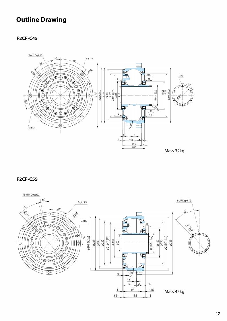
12. Outline Drawing
F2C-C25
Mass 12.5kg
F2CF-C35
Mass 21kg
17
Outline Drawing
F2CF-C45
Mass 32kg
F2CF-C55
Mass 45kg

18
Outline Drawing
F2CF-C65
Mass 62kg

MEMO
19

20
Warranty
Warranty Period
WarrantyCondition
WarrantyExclusions
Notwithstanding the above warranty, the warranty as set forth herein shall not apply to any problem or damage to the Product that is caused by :
1. installation, connection, combination or integration of the Product in or to the other equipment or machine that is rendered by any person or entity other than the Seller ;
2. insufficient maintenance or improper operation by the Buyer or its customers, such that the Product is not maintained in accordance with the maintenance manual provided or designated by the Seller ;
3. improper use or operation of the Product by the Buyer or its customers that is not informed to the Seller, including, without limitation, the Buyer,s or its customers, operation of the Product not in conformity with the specifications, or use of lubricating oil in the Product that is not recommended by the Seller ;
4. any problem or damage on any equipment or machine to which the Product is installed, connected or combined or on any specifications particular to the Buyer or its customers ;
5. any changes, modifications, improvements or alterations to the Product or those functions that are rendered on the Product by any person or entity other than the Seller ;
6. any parts in the Product that are supplied or designated by the Buyer or its customers ; 7. earthquake, fire, flood, sea-breeze, gas, thunder, acts of God or any other reasons beyond the control of the Seller ; 8. normal wear and tear, or deterioration of the Product,s parts, such as bearings, oil-seals ; 9. any other troubles, problems or damage to the Product that are not attributable to the Seller.
The warranty period for the Products shall be 18 months after the commencement of delivery or 18 months after the shipment of the Products from the seller's works or 12 months from the Products coming into operation, whether comes first.
In the event that any problem or damage to the Product arises during the“Warranty Period” from defects in the Product whenever the Product is properly installed and combined with the Buyer,s equipment or machines, maintained as specified in the maintenance manual, and properly operated under the conditions described in the catalog or as otherwise agree upon in writing between the Seller and the Buyer or its customers ; the Seller will provide, at its sole discretion, appropriate repair or replacement of the Product without charge at a designted facility, except as stipulated in the“Warranty Exclusions” as described below.
However, if the Product is installed or integrated into the Buyer,s equipment or machines, the Seller shall not reimburse the cost of : removal or re-installation of the Product or other incidental costs related thereto, any lost opportunity, any profit loss or other incidental or consequential losses or damages incurred by the Buyer or its customers.
The scope of our warranty for our products is limited to the range of our manufacture.
Warranty (period and contents)