aachen - gwdgwebdoc.sub.gwdg.de/ebook/serien/ah/aib/2002-05.pdf · aachener informatik berichte...
TRANSCRIPT
AachenDepartment of Computer Science
Technical Report
Modelling Requirementsand Architectures forSoftware Product Lines
Horst Lichter, Thomas von der Maßen and Thomas Weiler
ISSN 0935–3232 � Aachener Informatik Berichte � AIB-2002-05
RWTH Aachen � Department of Computer Science � February 2002

The publications of the Department of Computer Science of RWTH Aachen (AachenUniversity of Technology) are in general accessible through the World Wide Web.
http://aib.informatik.rwth-aachen.de/

Modelling Requirements and Architectures for SoftwareProduct Lines
Horst Lichter, Thomas von der Maßen and Thomas Weiler
Lehr- und Forschungsgebiet Informatik IIIRWTH Aachen, Germany
Email: �lichter, vdmass, thweiler�@cs.rwth-aachen.de
Abstract. The development of software product lines has become a new and promisingfield in software development in the last few years. Market asks for faster developmentof new software products which also must be cheap and of high quality. Here softwareproduct line engineering offers software companies the possibility to adress this marketneeds by also reducing the development costs.Software product line engineering is based on the domain engineering which provides abasis of core assets (also called platform), which in turn can be reused by thereon basedapplications in the application engineering. Thereby it is essential to model the variabilitywhich occurs among different applications derived from the platform.Within requirements engineering the specification of requirements only in natural lan-guage isn’t adequate to obtain a most possible complete and consistent description ofrequirements. Because existing notations aren’t adequat for modeling requirements forsoftware product lines a new approach is required.Also architecture modeling for software product lines requires new concepts for modelingthe common and variable parts of a software product line. Therefore software architec-tures for software product lines can be described by means of feature components whichrepresent a specific characteristic of the system to be modeled.This report adresses these problems and offers new concepts for their solution.
1 Introduction
The development of software product lines has become a new and promising field insoftware development in the last few years. The idea behind the concept of a softwareproduct line is not to build one software product after another, but to develop a prod-uct family in that each member shares a set of commonalities with all other membersand differs in particular aspects. This approach is very common in traditional engin-eering fields like for example the automobile industry or even the computer hardwareindustry.
Today most software applications are still constructed in a single-product-fashion. Onthe basis of customer requirements an application is created and once the applicationmeets the customer’s requirements the product is released. Because reuse is no strate-gic objective none or only small effort is invested in the identification and creation ofpossibly reusable elements which can be used in future projects. But, increased reuse isa key factor in software development to fasten the development process and to deliverproducts in time. The approach to develop a software product family for a particulardomain based on a common shared platform attempts to address this objective.
1.1 Evolution of Reusablity Concepts
Since its early days software engineering has regarded reusability an important objec-tive to be archieved and a central means to improve software development. For thisreason increasing reusability was always a goal when developing new methods, tech-niques, and languages.
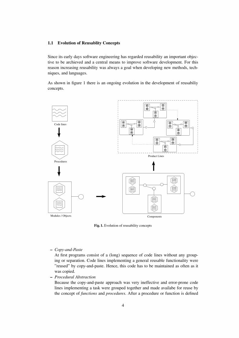
As shown in figure 1 there is an ongoing evolution in the development of reusabiliyconcepts.
Procedures
Code lines
Product Lines
ComponentsModules / Objects
Fig. 1. Evolution of reusability concepts
– Copy-and-PasteAt first programs consist of a (long) sequence of code lines without any group-ing or separation. Code lines implementing a general reusable functionality were”reused” by copy-and-paste. Hence, this code has to be maintained as often as itwas copied.
– Procedural AbstractionBecause the copy-and-paste approach was very ineffective and error-prone codelines implementing a task were grouped together and made availabe for reuse bythe concept of functions and procedures. After a procedure or function is defined
4

it can be called by its name together with its actual parameters as many times asneeded.
– Modules and ObjectsBut as the size of software systems grew only procedural abstraction which stillleads to monolithic systems remains unsatisfying. To develop large software sys-tems a concept was needed to divide the whole system into smaller units which canbe independently developed, tested and integrated. Each unit hides its inner struc-ture and complexity and offers an interface for external access. In the 70th modulesand later objects were introduced to implement the concept of information hidingi.e. to encapsulate data and to offer operations to manipulate this data.
– FrameworksBased on the object oriented concepts frameworks define a reusable architecturefor a class of applications. A framework defines the central abstractions and de-sign decisions for this application class. Based on a framework applications can bebuilt by subclassing abstract classes of the framework and by providing additionalclasses needed to complete an application. Concerning reusability frameworks fo-cus on both architecture and implementation reuse.
– ComponentsExperience shows that objects, classes, and inheritance are well suited to conc-truct applications and to increase reusability on a single application level. On theother side inheritance is a difficult means and leads to a very strong coupling ofthe classes involved. To overcome this problems, the concept of components wasintroduced. A component offers a set of useful and reusable functionality at its in-terfaces. A component can be reused in every context where its specific task mustbe solved. Components can be easily assembled resulting in a new application.
– Software Product LinesSoftware product lines are the latest and advanced concept of software reusabil-ity. The idea is not only to reuse components where similar tasks must be donebut also to reuse structures of collaborating components to solve similar prob-lems. This can be seen as a framework of higher-level software elements, whichabstractly describes the relation of components in a family of similar softwareproducts. Thereby component doesn’t necessarily mean components as used inJAVATM Beans, CORBATM or MicrosoftTM ActiveX/DCOM but a higher-level soft-ware element, which could also be again something like a framework. Softwareproduct lines therefore introduce a reuse strategy at a still higher abstraction levelas objects and components respecitvely and even frameworks.
1.2 Definitions
The Software Engineering Institute (SEI) at the Carnegie Mellon University gives thefollowing definition of a software product line:
”A software product line is a set of software-intensive systems sharing acommon, managed set of features that satisfy the specific needs of a particularmarket segment or mission and that are developed from a common set of coreassets in a prescribed way.” [SEI].
5

In that definition it is stressed, that the development is constrained by a prescribed way.The software products have to be built from a set of core assets instead of being builtseparately. A software product line is therefore a set of products that have a commoncore of characteristics - in this report called platform - and have a set of differentcharacteristics, the variable parts. Figure 2 shows this context.
Product 1 Product 2
Product 3
Platform
Fig. 2. Products and their shared platform
Closely related to the concept of a software product line is the concept of a productfamily. As early as 1976 David Parnas introduces this concept to the software engin-eering community [Par76]. Weiss et al. refine this concept in the context of softwareproduct lines [BSW99]. This refinement leads to the following stages in defining aproduct family:
– Potential product familyA set of software for which one suspects that there is sufficient commonality to beworth studying the common aspects of the software.
– Semi product familiyA set of software for which common and variable aspects have been identified.
– Defined product familyA semi-family for which an economic analysis has been performed in order todecide how much of an investment should be made in the family. This investmentexploits the commonalities and variabilities for the purpose of efficiently creatingfamily members.
– Engineered product familyA defined family for which the organizational and technical infrastructure has beenset up in order to develop the family members (i.e. the products).
Based on these definitions a software product line can be seen as an engineered productfamily where each product is launched, sold, and shipped seperately.
6

1.3 Expected Benefits
Reuse of high level artifacts is the main objective of the product line developmentapproach. As stated by Jacobson et. al. [JGJ97] reuse strategies have three major goals:
– Faster developmentTime to market has become a crucial factor for being successful in todays softwaremarkets. Reusing artefacts leads to shorter development times because productsare not build from scratch each time.
– Improved qualityOnly products that fit the users requirements and are of high quality are acceptedand used. We expect that the reuse of validated high quality artifacts leads to betterquality of the resulting new products.
– Reduced development and maintenance costsBecause product development is conceptionally based on reusing high quality ar-tifacts and products have not to be implemented from scratch the overall develop-ment costs will decrease. The same holds for the maintenance costs since only theproduct specific aspects must be developed and maintained separately.
By consequently applying reuse strategies in all development areas noticeable im-provements can be achieved. Jacobson et al. report the following improvements [JGJ97]:
– Factor 2 to 5 faster time to market– Factor 5 to 10 less error sensibility– Factor 5 to 10 less maintenance costs
The overall development costs are reduced of around 15% to as much as 75% for longterm projects. Furthermore, the application of reuse strategies creates highly adaptableproducts, consistently usable products and higher market agility.
2 Software Product Line Engineering
Because developing software product lines needs new or adapted methods and tech-niques a new engineering field called Software Product Line Engineering emerges.Software Product Line Engineering concerns with the definition of methods, tech-niques, tools, and processes to support software product line development. Each soft-ware product line must be carefully defined and planned. Its realization must be imple-mented with great disciplin. Therefore the development of a software product line putshigh demands on the whole software development process. A very high level processfor developing software product lines is given by the SEI. It defines the following threemain parts: Domain Engineering, Application Engineering, and Management (see 3)
Next we will describe these major aspects of software product line development inmore detail.
7

Fig. 3. High Level Product Line Engineering Process (acc. to [SEI])
2.1 Domain Engineering
By identifying common parts of similar products and major aspects of a given domainrespectively a basis of shared artifacts is created. This process is called Domain En-gineering. So the task of the domain engineering can be defined as: Identify similarstructures (features) from a set of related products or problems of a given domain andprovide a basis of elements which can be shared among thereon based applications.
This definition is consciously generally, because domain engineering doesn’t onlymean to provide a basis of shared software elements but also sharing similar documentsor document templates, requirements artefacts or (abstract) test cases for example.
Furthermore domain engineering may mean to analyze
– a given domain of a specific problem or– a set of closely related, already produced applications.
In the first case (the greenfield approach) the development of the platform is onlybased on the domain knowledge of the domain engineers. Therefore domain expertswith experiences in the regarded area are needed to fulfill this task. In the latter casethe common basis is created on the similarities among the analyzed products and alsoon base of the domain knowledge of the domain engineers.
The result of the domain engineering is a model defining the common platform of theproduct line. This domain model will be used by the application engineering to produceapplication models for each specific product.
8

Domain Engineering
PlatformSpecification
PlatformDesign
PlatformImplementation
PlatformEvolution
Fig. 4. Structure of the Domain Engineering Process
The domain engineering process can be divided into the activties depicted in figure 4.After the scope of the product line and the products belonging to the product line aredefined, a common architecture must be developed and the platform must be imple-mented. The maintenance and evolution of the platform is also part of this process.
2.2 Application Engineering
In the Application Engineering single products are created by (re-)using the artifactsprovided by the common platform (often called core assets), see figure 5.
Fig. 5. Domain and Application Engineering
For that purpose the specific features of an application to be build must be specifiedand determined. The domain model should support the application engineer in thistask by providing decision guidance which helps to map customer requirements tofeatures provided by the platform. Features might be provided by platform or might
9

also be special features which can - in the worst case - only be identified for a singleproduct. In the first case features and their implementation can be (re)used in the lattercase features must be newly specified and implemented. As will be shown in moredetail in section 5 the domain model will also help to determine which dependenciesexist between different features, so that the application engineer knows which depen-dent features must also be included if he decides to include a specific feature in theapplication. Figure 6 visualizes the main parts of the Application Engineering process.
Application Engineering
ProductSpecification
ProductDesign
ProductImplementation
ProductEvolution
Fig. 6. Structure of the Appication Engineering
2.3 Management
The main task of management is to coordinate the two processes (domain and appli-cation engineering), because they are not completed one after the other but are highlyperformed in parallel.
Hence, management plays a critical role in successfully developing a product line.Activities of both domain and application engineering must be given resources, theymust be coordinated, and supervised. Organizational management must set in placethe right organizational structure that makes sense for the enterprise, and make surethat the organizational units receive the right resources. Organizational management isthe authority that is responsible for the ultimate success or failure of the product lineeffort. Organizational management also contributes to the core asset list, by makingavailable for reuse those management artifacts (especially schedules and budgets) forproducing products in the product line.
The professional management of a product line development is a prerequisite to gainthe benefits of this approach. Experience shows that a developing organization musthave mature software development processes to move from single product develop-ment to the product line development approach. This holds especially from a manage-ment point of view.
In the following section some case studies in producing software product lines will bepresented and analyzed. These approaches often differ greatly from each other becausethey often are an adaption of existing methods and technologies which were used inthe companies before they decided to migrate to a product line based software develop-ment. Furthermore the different domains of this companies caused different solutions
10

which were adequat for the specific company but wouldn’t work for other companiesin general.
3 Practical and research experiences
Within literature and practice different approaches for the introduction and implemen-tation of a software product line can be found. In this section at first two of them shallbe presented. In section 5 this different approaches will slip into a first draft versionof a meta-model for the architecture of software product lines which tries to identifythe modeling elements needed to describe a domain architecture and a thereof derivedapplication architecture.
3.1 Domain-Oriented Engineering of Elevator Control Software
LG Industrial Systems Co. Ltd. (LGIS) is one of Korea’s leading suppliers of elevatorcontrol systems. The diversity of customers’ needs, rapidly changing market require-ments and the necessity to respond quickly to the actions of market competitors forcedLGIS to consider new ways in software developing. By utilizing reusable and adapt-able components LGIS achieved to reduce maintenance costs drastically [LKK�00].The method used can be divided into three parts, see figure 7
– Domain analysis– Separation of behaviour, function and implementation– Architecture based software composition and generation
Domain Engineering Within the domain analysis commonalities and differencesamong a family of products in terms of product features are analyzed. The resultsare then organized into a feature model, which is used to develop domain models (i.a.operational models, component models and architecture models). The feature modelonly represents the static aspects of a given domain, that is, it describes structuraland compositional aspects of the features. An example of a feature model of elevatorcontrol software is given in figure 8. The dynamic characteristics are modeled withthe help of message-sequence diagrams (MSD), statechards and data flow diagrams(DFD). This operational models describe how the features cooperate within the givendomain.
The features and their interaction are then modeled as components in a componentmodel. The purpose of this component modeling is to develop reusable and adaptablecomponents. Thereby the term component refers to any unit of reuse or integration,including computational components, interface components, communication compo-nents and implementation package components. In the next step components are de-composed into objects which are described by an object model.
11

Fig. 7. Domain-Oriented Engineering at LGIS [LKK�00]
In the last step an architecture model is produced which maps the logical structure pro-vided by the operational models to the physical configuration of the problem domain.This may mean to map the logical structure on a centralized or a distributed IO ControlSystem.
Application Engineering Application engineering is a process to obtain an exe-cutable source code while utilizing models developed in the domain engineering phase[LKK�00]. This is done by selecting the necessary features for a spezific productwhich in turn requires to select the components needed. Based on this selection auto-matic code generation is used to produce executable code for the spezific applicationwithin the given architectural environment. Thereby only two JAVA classes are gener-ated - one for the program logic and one for the data used in the program logic.
This approach surely can only be used in domains where problems can easily describedby state machines - as it is the case for elevator control software - which can be imple-mented the way it is done in the given example by LGIS. In the next section softwareproduct line development at Cummins Engine Company will be presented. Therebyfocus will be layed upon the problems which arrise in introducing and executing soft-ware product lines in a company.
12

Fig. 8. Feature model of elevator control software [LKK�00]
3.2 Software Product Line Development at Cummins
Around 1994 Cummins Engine Company established a software product line for itsreal-time embedded diesel engine controls in cooperation with the Software Enginee-ring Institute (SEI) of Carnegy Mellon University [Dag00]. The results of this projectalso sliped in the framework for software product line practice developed at the SEI[SEI] which tries to give an overall description of software product lines. The soft-ware product line program at Cummins slashed development costs and time to marketand launched many successful products. But the introduction of software product lineswasn’t without throwbacks. Five years after Cummins started to use a product linebased approach in software development the overall reuse effort was reduced by 50percent. Therefore management of Cummins decided to analyze this evolution whichleads to the following results
– Components and interfaces were to complex
13

– Insufficient domain analysis resulted in frequently changed components which inturn caused instability of components
– Lack of training for software developers in applying the product line– Distribution of configuration management resulting in non-synchronized reposito-
ries– Lack of a product line supporting development process– Insufficient documentation of requirements, architecture and design decision
Furthermore the analysis showed the necessity to concentrate of spezific parts of anoverall software architecture by separation of concern. Consequently a lack of toolswhich suport different views on an architecture was stated.
Besides that reviews were introduced to improve the communication between cus-tomers and developers but also within development teams and to eliminate errors, mis-understanding and inaccuracy in early phases of the software development process.This was essential for the development of software product lines because inaccuracyin early phases of the domain analysis resulted in errors which affected every productwhich is based on the errorness domain model. All this change of structure resulted inthe development of a completely new product line basis which is actually be used atCummins to improve their software product line approach.
As shown in this section modeling software product lines requires specific modelingelements not found in ”conventional” software engineering. Features for example areused to designate a behavioural or quality characteristic of a domain and applicationrespectively. As stated in section 1 this feature modeling is at a still higher abstrac-tion level then components or even frameworks. These features can be grouped intocommon and variable features found in all respectively few applications.
Furthermore the possibility to concentrate on specific aspects of the overall systemarchitecture is still more important for complex architectures like software productlines. In section 5 the required modeling elements for modeling software product linesshould therefore be identified and structured by a meta model.
4 Requirements Engineering for Software Product Lines
4.1 Overview
In this section we will discuss the main problems of the requirements engineering pro-cess for software product lines. In section 4.2 the new topics and problems concerningthe requirements engineering process will be presented. Furthermore various charac-teristics of a product line are mentioned and requirements for a requirements engin-eering model that supports software product line development will be presented. Oneof the main tasks in requirements engineering for software product lines is to capturevariability. In section 4.3 we present requirements for a graphical notation to modelvariability. Further we analyse two existing notations for modelling variability in re-quirements and find out that none of them is able to fulfill all the requirements that
14
have been elicitated. Finally we present a conclusion and discuss related and futurework on this topic.
4.2 Requirements Engineering for Software Product Lines
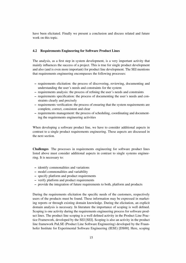
The analysis, as a first step in system development, is a very important activity thatmainly influences the success of a project. This is true for single product developmentand also (and is even more important) for product line development. The SEI mentionsthat requirements engineering encompasses the following processes:
– requirements elicitation: the process of discovering, reviewing, documenting andunderstanding the user´s needs and constraints for the system
– requirements analysis: the process of refining the user´s needs and constraints– requirements specification: the process of documenting the user´s needs and con-
straints clearly and precisely– requirements verification: the process of ensuring that the system requirements are
complete, correct, consistent and clear– requirements management: the process of scheduling, coordinating and document-
ing the requirements engineering activities
When developing a software product line, we have to consider additional aspects incontrast to a single product requirements engineering. These aspects are discussed inthe next section.
Challenges The processes in requirements engineering for software product lineslisted above must consider additional aspects in contrast to single systems enginee-ring. It is necessary to:
– identify commonalities and variations– model commonalities and variability– specify platform and product requirements– verify platform and product requirements– provide the integration of future requirements to both, platform and products
During the requirements elicitation the specific needs of the customers, respectivelyusers of the products must be found. These information may be expressed in market-ing reports or through existing domain knowledge. During the elicitation, an explicitdomain analysis is necessary. In literature the importance of scoping is well defined.Scoping is one activity during the requirements engineering process for software prod-uct lines. The product line scoping is a well defined activity in the Product Line Prac-tice Framework, developed by the SEI [SEI]. Scoping is also an activity in the productline framework PuLSE (Product Line Software Engineering) developed by the Fraun-hofer Institute for Experimental Software Engineering (IESE) [DS00]. Here, scoping
15
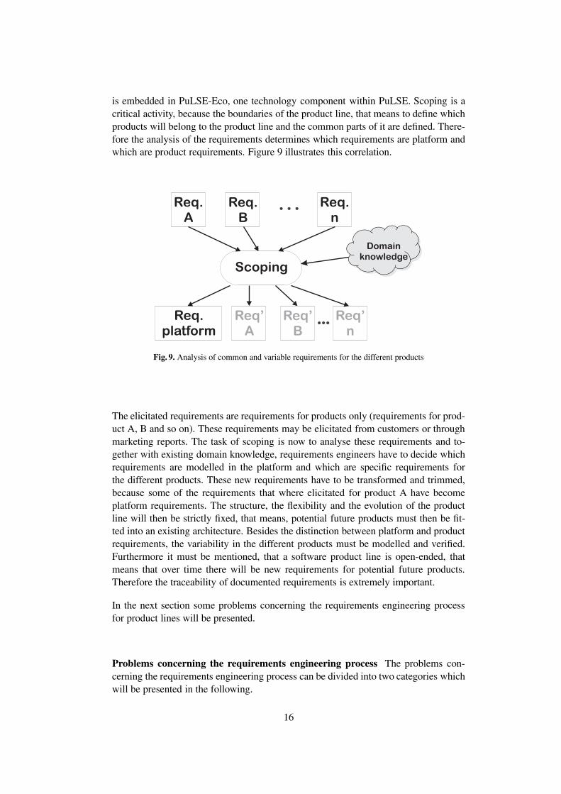
is embedded in PuLSE-Eco, one technology component within PuLSE. Scoping is acritical activity, because the boundaries of the product line, that means to define whichproducts will belong to the product line and the common parts of it are defined. There-fore the analysis of the requirements determines which requirements are platform andwhich are product requirements. Figure 9 illustrates this correlation.
Req.A
Req.B
Req.n
Req.platform
Req’A
Req’B
Req’n
Scoping
Domainknowledge
Fig. 9. Analysis of common and variable requirements for the different products
The elicitated requirements are requirements for products only (requirements for prod-uct A, B and so on). These requirements may be elicitated from customers or throughmarketing reports. The task of scoping is now to analyse these requirements and to-gether with existing domain knowledge, requirements engineers have to decide whichrequirements are modelled in the platform and which are specific requirements forthe different products. These new requirements have to be transformed and trimmed,because some of the requirements that where elicitated for product A have becomeplatform requirements. The structure, the flexibility and the evolution of the productline will then be strictly fixed, that means, potential future products must then be fit-ted into an existing architecture. Besides the distinction between platform and productrequirements, the variability in the different products must be modelled and verified.Furthermore it must be mentioned, that a software product line is open-ended, thatmeans that over time there will be new requirements for potential future products.Therefore the traceability of documented requirements is extremely important.
In the next section some problems concerning the requirements engineering processfor product lines will be presented.
Problems concerning the requirements engineering process The problems con-cerning the requirements engineering process can be divided into two categories whichwill be presented in the following.
16
Management problems As said before, professional management is cruical for suc-cessfully developing a software product line. Problems to be mastered may be e.g.
– CommunicationA lot of communication is needed to coordinate the domain and the various appli-cation engineering processes concerning requirements management. If this com-munication is not set up adequately and not monitored, problems in identifyingand classifying of requirements will arise.
– Right requirements classificationDuring platform and product maintenance new requirements must be integratedproperly. Often it is not not clear, whether new requirements should be integratedin the platform or are specifc for one product. Wrong decisions regarding thisrequirements classification lead often to implementing requirements in products,which belong obviously into the platform. These decisions must be made explicitlyby a change control board that is responsible for all products of a product line.
– Measuring benefitsA serious problem is to value the costs and the benefits of the platform develop-ment. This can be done be regarding the return of investment for a product linedevelopment, i.e. defining at which point the large expense at the beginning of theproduct line development will be leveled and the whole project becomes profitable.
Methodical problems Methodical problems cover problems concerning methods andnotations to model common and variable aspects of the product line. We will see insection 5.3, that there is no special method or notation to express variability in re-quirements. Therefore existing notations are taken and modified to suit to the needsof the requirements engineer but until now, no notation is applicable to fulfill all therequirements that were put on such a notation.
Another important aspect is the lack of suitable tools supporting the requirements en-gineering activities for product lines. That means tools to model and trace platformand product requirements as well as commonalities and variations.
4.3 Modelling variability
With respect to the methodical problems mentioned above, a notation is required, thatis able to express variability. Variability expresses that a part of the system deviatesin a defined way. So called variation points can be defined. In these points different,concrete variants can be chosen to resolve this variation point. For example we wantto consider to administer bank accounts in a homebanking-system. At these variationpoint it is possible to administer giro accounts and/or fixed deposit accounts, whereasit should always be possible to manage giro accounts. Examining this simple example,it is necessary to distinguish between different types of variability and relationshipsbetween variations. The following types of variability must be considered:
– options
17

– alternatives
Optional aspects of a system can be integrated or not. That means from a set of optionalaspects, any quantity of these aspects can be choosen, including none or all. Hence,so optional aspects can be modelled by means of an or-relatonship. From a set ofalternative aspects, only one aspect can be choosen - defining an exclusive-or (xor)-relationship.
Besides the distiction of the different types of variability, the relationships betweenthe variable parts must be defined, too. These relationships define constraints withrespect to the choice of variant parts. The following constraints are needed to expressthe different relationships:
– implied– equivalent– mutual exclusiv
The implied-relationships (A, B) expresses, that if aspect A is choosen the impliedaspect B must be choosen, too, whereas an equivalent-relationship is an implied-relationship in both directions. An exclusiv-relatonship (A, B) expresses, that if aspectA is chosen, it is not allowed to choose aspect B as well, and vice versa.
To express variability it is necessary to model variation points. A variation point is alocation within the system where functionality differs in some way. This differentia-tion will be examined later in this section. In the first place it is necessary to stressthe importance to supplement natural-language requirements specifications with semi-formal notations. By the majority, in practice requirements specification are composedin natural language. In spite that it is possible to write correct, clear and sound requi-rements in natural language [Rup01] it is very difficult to express variability. Anotherpoint is, that the various products have to be discussed with domain experts, respec-tively the customers in a way that both sides can understand what the potential systemsshould be able to perform.
Requirements for a notation to model variability As usual notations can be graphi-cal a textual or a mixture of both. The advantage of modelling variability in a graphicalnotation is, that variation points are recognized much easier than in a pure textual de-scription. In this section we want to present the requirements that have to be put on anotation that provides to express variability in Software Product Lines. The followingrequirements have been identified:
– representation of common and variable parts– distinction between types of variability– representation of dependencies between variable parts– providing different views– possibility to add future requirements easily
18

– providing good tangibility for domain experts and system developers
Representation of common and variable parts. In a graphical representation it mustbe possible to express common and variable parts of the system. That means thereis a need of a graphical element to express aspects that belong to the platform andtherefore shared by every product of the product line. Another element is needed toexpress variations at a specific point.
Distinction between types of variability. The notation must be able to express differ-ent types of variable parts. Types of variability comprises that there are optional andalternative parts. Optional means that these aspects may belong or may not belong to asystem, whereas between two or more alternative aspects an exclusive-or relationshipexists.
Representation of dependencies between variable parts. The description of depen-dencies is mandatory. Dependencies between variable parts are implied, equivalentand xor-relationships. An implied-relationship means, that if one aspect is needed,than another aspect must be taken into the system as well. An equivalent-relationshipis an implied-relationship in both directions and a xor-relationship expresses that onlyone aspect from a set of aspects can be taken into the system.
Providing different views. Using the notation it should be possible to model at leasttwo different views on the product line. It must be possible to model the product line asa whole, comprising the common and the variable parts - the platform and the variousproducts. The representation of only one product must be mandatory, too, taking intoaccount that one product consists of parts taken from the platform and parts that arespecific for this one product.
Possibility to add future requirements. Future requirements must be added easily,that means without changing the structure of the existing parts of the system, becausenew requirements will arise for future products of the product line.
Providing good tangibility. In most cases domain experts do not want or are notable to understand formal specifications. On the other side, they do not want to readunstructured natural language specification, but want to get a first view of the system.So a graphical representation might help to understand the relevant parts very easily.
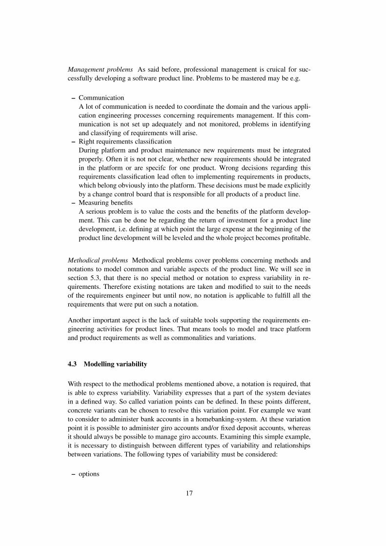
It is important to mention that the graphical notation should not replace natural lan-guage specifications but to supplement them and to provide a different view on thesame context (see figure 10). It is mandatory to abstract from conrete requirements.The combination of requirements specified in natural language and a graphical rep-resentation should be supported by a capable requirements-template [Rup01,RR00].This template should be modified in the way that it provides sections for platform andproduct requirements.
In the next section we analyse two notations with regard to the listed requirements onsuch a notation:
19
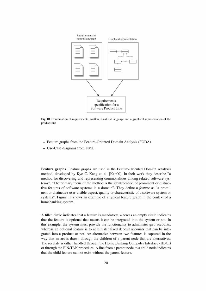
Fig. 10. Combination of requirements, written in natural language and a graphical representation of theproduct line
– Feature graphs from the Feature-Oriented Domain Analysis (FODA)
– Use-Case diagrams from UML
Feature graphs Feature graphs are used in the Feature-Oriented Domain Analysismethod, developed by Kyo C. Kang et. al. [Kan00]. In their work they describe ”amethod for discovering and representing commonalities among related software sys-tems”. ”The primary focus of the method is the identification of prominent or distinc-tive features of software systems in a domain”. They define a feature as ”a promi-nent or distinctive user-visible aspect, quality or characteristic of a software system orsystems”. Figure 11 shows an example of a typical feature graph in the context of ahomebanking-system.
A filled circle indicates that a feature is mandatory, whereas an empty circle indicatesthat the feature is optional that means it can be integrated into the system or not. Inthis example, the system must provide the functionality to administer giro accounts,whereas an optional feature is to administer fixed deposit accounts that can be inte-grated into a product or not. An alternative between two features is captured in theway that an arc is drawn through the children of a parent node that are alternatives.The security is either handled through the Home Banking Computer Interface (HBCI)or through the PIN/TAN procedure. A line from a parent node to a child node indicatesthat the child feature cannot exist without the parent feature.
20

Homebanking-System�
Administer account� Transaction� Security�
Giro account� Fixed deposit account� Bank transfer� PIN/TAN�HBCI�Debit�
mandatory� optional� alternative�
Fig. 11. Feature graph from FODA
EvaluationThe feature graphs provide a good understandable representation of common and vari-able parts. Common features, which are platform candidates can be identified trough afilled circle. Variable features are divided into optional and alternative features. The us-age of the feature concept abstracts additionaly from concrete requirements [SGB00]and new features - generated from new requirements can be integrated easily.
Besides these advantages the feature graphs do not meet all the requirements. De-pendencies between features can only be modelled implicitly through alternatives andparent-child relationships. It is not possible to model equivalent relationships or xor-relationships between features which are not alternatives. Furthermore, platform fea-tures may be scattered over the whole diagram. That makes it difficult to recognize thecommon parts directly.
Use Case diagrams The second notation we have examined, are the Use Case dia-grams. These diagrams provide the possibility to model Use Cases. A Use Case de-scribes a sequence of events, initiated by the user, here called actor, of the system.Furthermore it describes the interactions between the actor and the system. Use Casediagrams represent the textual target-state description of Use Cases in a graphical no-tation.
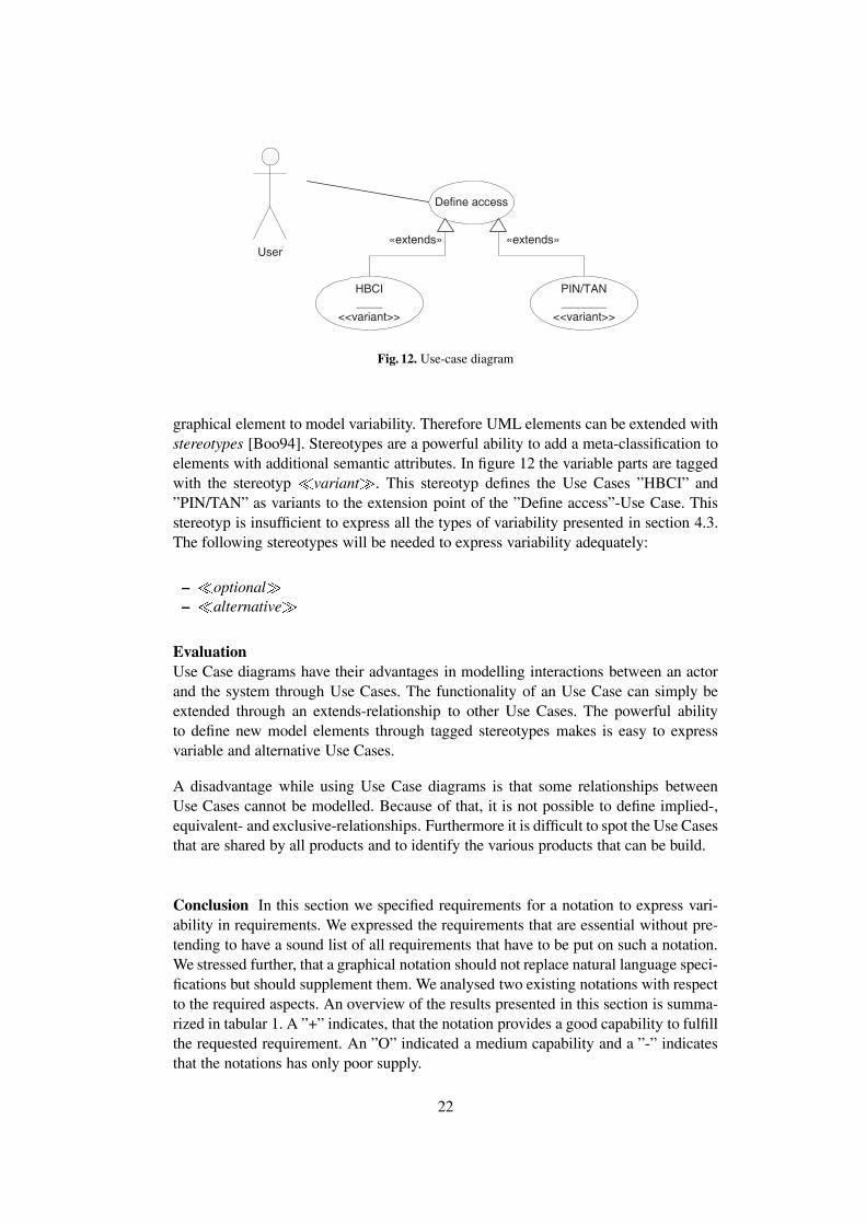
In these diagrams it is also possible to model relationships between various Use Cases.Use Cases can use other Use Cases to fulfill their duty. Through the inheritance-relationship, a super-Use-Case can be declared as extension points and the sub-Use-Cases define the actions that are embedded in the super-Use-Case. That means one UseCase can be embedded in another Use Case through an extends-relationship [Jac92].Figure 12 shows an example of a Use Case in the homebanking context.
In this example, the use case ”Define access” is defined. The two sub-Use Cases”HBCI” and ”PIN/TAN” define the steps the user must perform in the homebanking-system to install the process, provided by his bank. The Use Case diagrams provide no
21
Define access�
HBCI�____�
<<variant>>�
PIN/TAN�_______�
<<variant>>�
«extends»� «extends»�User�
Fig. 12. Use-case diagram
graphical element to model variability. Therefore UML elements can be extended withstereotypes [Boo94]. Stereotypes are a powerful ability to add a meta-classification toelements with additional semantic attributes. In figure 12 the variable parts are taggedwith the stereotyp �variant�. This stereotyp defines the Use Cases ”HBCI” and”PIN/TAN” as variants to the extension point of the ”Define access”-Use Case. Thisstereotyp is insufficient to express all the types of variability presented in section 4.3.The following stereotypes will be needed to express variability adequately:
– �optional�– �alternative�
EvaluationUse Case diagrams have their advantages in modelling interactions between an actorand the system through Use Cases. The functionality of an Use Case can simply beextended through an extends-relationship to other Use Cases. The powerful abilityto define new model elements through tagged stereotypes makes is easy to expressvariable and alternative Use Cases.
A disadvantage while using Use Case diagrams is that some relationships betweenUse Cases cannot be modelled. Because of that, it is not possible to define implied-,equivalent- and exclusive-relationships. Furthermore it is difficult to spot the Use Casesthat are shared by all products and to identify the various products that can be build.
Conclusion In this section we specified requirements for a notation to express vari-ability in requirements. We expressed the requirements that are essential without pre-tending to have a sound list of all requirements that have to be put on such a notation.We stressed further, that a graphical notation should not replace natural language speci-fications but should supplement them. We analysed two existing notations with respectto the required aspects. An overview of the results presented in this section is summa-rized in tabular 1. A ”+” indicates, that the notation provides a good capability to fulfillthe requested requirement. An ”O” indicated a medium capability and a ”-” indicatesthat the notations has only poor supply.
22

Feature graphs Use Case diagrams
Representation of common and variableparts
+ O
Distinction between types of variability + ORepresentation of dependencies be-tween variable parts
O -
Providing different views on productline and products
+ +
Possibility to add future requirementseasily
+ +
Providing good tangibility for domainexperts and developer
O O
Table 1. Comparison of feature graphs and Use Case diagrams
Both notations have their advantages: Both do abstract from concrete requirementsand are able to express the requested variability. Both are well understandable and it ispossible to integrate new requirements very easily. With the elements of the notationsit is possible to model a product line and a single product view. On the other hand,both notations lack on expressing dependencies between variable and common partsdirectly. The feature graphs comprises dependencies indirectly whereas the Use Casediagrams are not able to express relationships, besides use- and extends-relationships,at all.
4.4 Conclusion and future work
Conclusion In this section we gave an overview of the requirements engineering pro-cess in the context of Software Product Lines. In section 4.2 we expressed the new as-pects that arouse while implementing the requirements engineering process for productlines and pointed at the problems that will additionally come up in that process. One ofthe main tasks in documenting requirements for a product line is to model the commonparts, shared by all potential products and the variable parts, that belong to a specificvariant. There is indeed a demand for a graphical, semiformal notation to express theseparts to get an better overview of what the products should perform. In section 4.3 weput on several requirements on such a notation. Furthermore we analysed two existingnotations, the feature graphs from the Feature-Oriented Domain Analysis and the UseCase diagrams from the UML. Both notations have their advantages and disadvantagesand both are not capable to fulfill all the requirements that were put on.
Related work The following list gives an overview of related work on requirementsengineering for Software Product Lines and Domain engineering:
1. Sofware Engineering Institute (SEI). It offers the Framework for Product LinePractice and presents the Feature Oriented Domain Analysis.Available at: http://www.sei.cmu.edu
23

2. Fraunhofer Institut Experimentelles Software Engineering (IESE). The institutepresents the PuLSE-framework. PuLSE provides a complete framework that cov-ers the whole software product line development life cycle, including reuse infras-tructure construction, usage, and evolution. PuLSE-Eco and PuLSE-CDA are thecomponents of the framework that deal with economic scoping and customizabledomain analysis.Available at: http://www.iese.fhg.de
3. TU Ilmenau Fachgebiet Prozessinformatik - Projekt Alexandria. The project workaims towards a general method for developing system families, which will inte-grate existing methods.Available at: http://www.theoinf.tu-ilmenau.de/�pld/pub/index.html
4. Chair for Software Systems Engineering - University of Essen. The institute re-searches in requirements engineering for product lines using Use Cases.Available at: http://sse.informatik.uni-essen.de/
Furthermore, the GI-Arbeitskreis ”Requirements Engineering fur Produktlinien” of theGI Fachgruppe 2.1.6 is analyzing selected industrial Software Product Line scenariosin order to determine special problems in different contexts and to recognize some kindof problem pattern and to find solutions to those problems. A final report describingthe results will be published soon.
Future work The current studies deal with the enhancement of the feature graphsand the change of the UML-Metamodel to express variability directly and not throughthe usage of stereotypes in UML. Therefore new elements are needed to express thedifferent types of variability and the relationships between them. The objective is topresent a notation that fulfills the demands to model variability in software productlines. In future studies the integration of representing variability of requirements intorequirements templates will be analysed. The objective is to support the requirementsengineer in documenting the requirements of the platform and of the various products.
Concurrently a diploma thesis deals with the applicability of existing cost estimationmodels on the development of Software Product Lines. The goal of this work is to anal-yse at which points, existing methods are not able to take into account the variabilityof system families, like in Software Product Lines.
5 Architecture Modeling
The task of architecture modeling is to create a structure plan or a blueprint for thesystem to be build. The architecture of a software system can be split into two areas
– Static structure– Dynamic structure
24

The static structure describes which elements of the system to be build are in relation-ship with other elements of the system. The dynamic structure describes how theseelements interact to realize the system’s functionality. Therefore the static structurecan be called the Who whereas the dynamic structure describes the How of the sys-tem. Although current praxis of modeling software architectures often focuses solelyon the static structure as represented by for example UML class diagrams, both as-pects, static and dynamic structure, are essential for software architectures and shouldtherefore taken into account when constructing a metamodel for SPL architectures.
Architecture modeling for software product lines can be seen as a four layer modelas presented in Figure 13. The top level SPL Architecture Metamodel describes the
Fig. 13. Four layer model for software product line architectures
modeling elements needed to build models of the underlying level, the Domain Ar-chitecture. These modeling elements will be described in more detail in section 5.2.The Domain Architecture describes the overall structure of thereon based ApplicationArchitectures and provides the designer with customization possibilities among whichhe has to choose to build a concrete Application Architecture which is in turn theconstruction plan for a ready build product, an Application.
5.1 Feature Components
The central building blocks of the Domain and Application Architecture are FeatureComponents. A feature component can be seen as a self-contained unit, which repre-sents a specific characteristic of the system to be modeled. They are an adaption of thefeature concept introduced by the Feature Oriented Domain Analysis (FODA) [Kan00]
25

to the level of architecture modeling for software product lines. It must be mentionedthat the feature components at the level of architecture modeling aren’t necessarilyidentical to the features identified at the level of the domain analysis. For example itmight be possible that a set of features identified in the domain analysis together build afeature component at the architecture modeling level. Furthermore feature componentsneed not to be realized as components provided by for example Corba or MicrosoftCOM/ActiveX.
The feature components can be divided into three different types as shown in figure 14
– Common Feature Components: They are used in a domain architecture and de-scribe components which can occur in every application based on this domainarchitecture. Common Feature Components occur in derived application architec-tures without modification.
– Variable Common Feature Components: These are Common Feature Compo-nents which can occur in every derived application architecture only by specifyingthe variability offered by the component.
– Specific Feature Components: They are special building blocks needed to con-struct a specific architecture derived from a domain architecture.
Feature Component�
Common Feature Component� Specific Feature Componet�Variable Common Feature Component�
Fig. 14. Feature Components
The possible variations which can occur at Variable Common Feature Componentswill be described in detail in the following section.
5.2 SPL Architecture Metamodel
In this section a first draft of a SPL Architecture Metamodel will be given, see fig-ure 15. The Domain Architecture describes the overall structure of applications whichare based on it. It consists of a set of Common Feature Compontens which wereshared among the applications, a set of Variable Common Feature Components, seesection 5.1, and a set of Relations which interconnect the different feature components.
26

Domain Architecture� Feature Component�
Common Feature Component� Specific Feature Componet�
Relation End�Relation�
Dependency�
Variability�
Prohibited� Implied�
Choice�
Alternative� Option�
Decision Support�
1� 1�
1� 2..*�
Extension�
Definition�
Redefinition�
Refinement�
1�
2..*�
1�
*�
1�
1..*�
1�
*�
Variable Common Feature Component�
Fig. 15. SPL Architecture Metamodel
27

The different types of feature components were presented in the last section. It wasmentioned that Variable Common Feature Components differ from Common FeatureComponents by offering the possiblity to modify the feature component. This variabil-ity can occur in four different ways:
– Extension: A feature component must be extended with regard to behaviour in aderived application architecture
– Definition: A feature component must be defined with regard to behaviour in aderived application architecture
– Redefinition: A feature component must be redefined with regard to behaviour ina derived application architecture
– Refinement: A feature component must be refined with regard to behaviour in aderived application architecture
Every Variable Common Feature Component includes a note (written in natural lan-guage) which helps the designer in processing the different types of variance.
Feature Components are interconnected with the help of relations. Thereby each re-lation consists of a set of relation ends where each end is connected to exactly onefeature component. The relations can be devided into two types
– Choice: A choice allows the designer to choose a - possibly empty - set of fea-ture components among a set of offered feature components. Therefore the choiceprovides a decision support which helps the designer to come to a decision. Thechoice can further be refined into two additionaly different kinds:� Alternative: The designer has to choose exactly one feature component among
a set of offered feature components.� Option: The designer has to decide to choose a feature component or not.
– Dependency: A set of feature components, where the existence of one featurecomponent depends on another feature component. This abstract type can be re-fined into two concrete types� Prohibited: A prohibited dependency between two feature components � and� means that the existence of feature component � forbids the existence offeature component � in a derived application architecture and vice versa.
� Implied: An implied dependency from feature component � to feature compo-nent � means that the existence of feature component � enforces the existenceof feature component �. That is feature component � cannot exist without theexistence of feature component � in an derived application architecture.
5.3 Application Architecture
Every application architecture which is based on a domain architecture must providean instantiation for the variable feature components which occur in the domain archi-tecture and a choice among the feature components offered by a choice in the domainarchitecture. Furthermore each application architecture may include a set of Specific
28
Feature Components, which describe feature components not included in the domainarchitecture but which are possibly shared among several applications. Therefore theapplication architecture may also include - with respect to the domain architecture- new relations between the Specific Feature Components and the Common FeatureComponents found in the domain architecture and between the Specific Feature Com-ponents themselves.
Thereby the differentiation in Common Feature Components and Specific FeatureComonents is not unchangeable. Within the evolution of a software product line aSpecific Feature Component can become a Common Feature Component. This maylead to a growing complexity of the domain architecture where separation of concernbecomes more and more important. This is among others one aspect which should beconsidered in the development of a metamodel for software product line architecturesas will be shown in the next section.
5.4 Future Work
In this section some problems in modeling software product line architectures shouldbe presented which require future research work. At first the term Feature Componentmust be stated more precisely. It must be examined how to find the edges of a Fea-ture Component. Furthermore an adequat notation and semantic for the definition ofFeature Components must be given.
Furthermore the metamodel presented in section 5.2 should be proofed by means of a(not to complex) example to validate the identified modeling elements and to identifypossibly missing modeling elements.
In addition a way to model collaborations of Feature Components must be given.Thereby modeling of static structure as well as dynamic behaviour must be possi-ble. Because these collaborations tend to be very complex a mechanism to focus onspecific parts of an overall system (separation of concern) must be developed.
Moreover the evolution of software product lines requires the possibility to insert (Spe-cific) Feature Components in the set of Common Feature Components and therefore inthe domain architecture. Furthermore it is necessary to trace the evolution of a softwareproduct line in order to trace design decisions.
Finally existing modeling (quasi) standards like the UML [OMG01] should be ana-lyzed whether respectively to which level they fulfill the requirements for modelingsoftware product lines and where already existing concepts must be extended.
6 Conclusion
As shown in this report, single-product development is not always an adequate way insoftware development. Market asks for faster development of new software products
29

which also must be cheap and of high quality. Here software product line engineeringoffers software companies the possibility to adress this market needs by also reducingthe development costs. Therefore the high demands on software companies, which areconditional upon more and more growing and changing customer requirements andalso a more and more narrow market, can be fulfilled nearly without loss of earnings.
Software product line engineering is based on the domain engineering which providesa basis of core assets (platform), which in turn can be reused by thereon based appli-cations in the application engineering. Thereby it is essential to model the variabilitywhich occurs among different applications derived from the platform. As was shownin sections 4 and 5 this is crucial for requirements engineering as well as for modelingsoftware architectures for software product lines.
Within requirements engineering the specification of requirements only in natural lan-guage isn’t adequate to obtain a most possible complete and consistent description ofrequirements. Because existing notations for requirements like FoDA and Use Casesdon’t fullfil all the requirements mentioned in section 4, like for example modelingdependencies between features, a new approach is required.
In section 5 a draft metamodel for architecture modeling for software product lineswas given. This metamodel describes software architectures for software product linesby means of feature components. A feature component can be seen as a self-containedunit, which represents a specific characteristic of the system to be modeled. Therebythe feature components are differentiated into common feature components, variablecommon feature components and specific feature components. The feature componentsare in relationship among one another whereas the existence of one feature componentmay depend on the the existence of another feature component (Dependency). Fur-thermore a domain architecture may provide the possibility to choose a set of neededfeature components among a set of offered feature components (Choice).
Future work will focus on the development of an adequate notation for the descriptionof requirements as well as for architecture modeling for software product lines. There-fore existing quasi standards like the UML should be analyzed and adapted wherenecessary to fulfill the requirements for a usefull notation as stated in this report.
7 Glossary
Application: A ready build software product.
Application Architecture: A construction plan for an application.
Architecture: A construction plan. Used as synonym for model.
Common Feature Component: A Feature Component which can occur in every de-rived application architecture without modification.
30

Core Asset : A software artifact that is used in the production of more than one productin a product line A core asset may be an architecture, a software component, a processmodel, a plan, a document or any other useful result of building a system.
Domain Architecture: A construction plan for the overall structure of applicationswhich are based on it.
Feature Component: A self-contained unit, which represents a specific characteristicof the System to be modeled.
Metamodel: A model which describes the modeling elements needed to build a model.
Model: A construction plan, see also architecture.
Platform : Core software asset base that is reused across systems in the product line.
Product Line : A group of products sharing a common, managed set of features thatsatisfy specific needs of a selected market or mission area.
SPL Architecture Metamodel: A model which describes the modeling elements neededto build a domain architecture.
Variable Common Feature Component: A Common Feature Comonent which canoccur in every derived application architecture only by specifying the variability of-fered by the component.
References
[BCS00] D. Batory, Rich Cardone, and Y. Smaragdakis. Software Product Lines - Experience andResearch Directions, chapter Object-Oriented Frameworks and Product Lines, pages 227–247. Kluwer Academic Publishers, 2000.
[Boo94] Grady Booch. Objektorientierte Analyse und Design. Addison-Wesley Verlag, 1994.[BSW99] W Bartussek, P. Strooper, and D. Weiss. Defining Software Families, pages 35–40. Dagstuhl-
Seminar-Report: 230, 1999.[Dag00] J.C. Dager. Software Product Lines - Experience and Research Directions, chapter Cummins’s
Experience in Developing a Software Product Line Architecture for Real-time EmbeddedDiesel Engine Controls, pages 23–45. Kluwer Academic Publishers, 2000.
[DS00] Jean-Marc DeBaud and Klaus Schmidt. A systematic approach to derive the scope of softwareproduct lines. Fraunhofer Institute for Experimental Software Engineering (IESE), Kaiser-slautern, 2000.
[GJC00] Cristina Gacek, Jean Jourdan, and Michel Coriat, editors. Proceedings of Product Line Archi-tecture Workshop, The First Software Product Line Conference (SPLC1). Fraunhofer IESE,August 2000. IESE-Report No. 053.00/E, Version 1.0.
[Jac92] Ivar Jacobson. Object-Oriented Software Engineering - A Use Case Driven Approach.Addison-Wesley Verlag, 1992.
[JGJ97] Ivar Jacobson, Martin Griss, and Patrik Jonsson. Software Reuse, Architecture, Process andOrganization for Business Success. Addison Wesley, 1997.
[Kan00] Kyo et al. Kang. Feature-oriented domain analysis (foda) feasibility study. Technical report,SEI, Carnegie Mellon University, Pittsburgh, PA, 2000.
[KN00] T. Kishi and N. Natsuko. Software Product Lines - Experience and Research Directions,chapter Aspect-Oriented Analysis for Product Line Architecture, pages 135–145. KluwerAcademic Publishers, 2000.
31

[KS00] Peter Knauber and Giancarlo Succi, editors. Proceedings of Software Product Lines: Eco-nomics, Architectures, and Implications. Fraunhofer IESE, June 2000. IESE-Report No.070.00/E, Version 1.0.
[LKK�00] K Lee, K.C. Kang, E. Koh, W. Chae, B. Kim, and B. Choi. Software Product Lines - Expe-rience and Research Directions, chapter Domain-Oriented Engineering of Elevator ControlSoftware - A Product Line Practice, pages 3–22. Kluwer Academic Publishers, 2000.
[OMG01] OMG. Unified modeling language specification, version 1.4. Technical report, OMG, 2001.[Par76] D.L. Parnas. On the design and development of program families. IEEE Trans. on SE, SE-
2:1-9, March, 1976.[RR00] James Robertson and Suzanne Robertson. Volere requirements specification template. At-
lantic System Guild www.systemguild.com, 2000.[Rup01] Chris Rupp. Requirements-Engineering und -Management. Hanser Verlag, 2001.[SEI] SEI/CMU. A framework for software product line practice - version 3.0.
http://www.sei.cmu.edu.[SGB00] Mikael Svahnberg, Jilles van Gurp, and Jan Bosch. On the notion of variability in software
product lines. University of Karlskrona/Ronneby, Department of Software Engineering andComputer Science, 2000.
32

Aachener Informatik-Berichte
���� �� � ���� � ��� � ���� ���� ������ �� ����� ������ � ���� ���� �����
������ �� ���� ������������ ���������������� ���� � �� � ��� ������
��� � ������������������ ��� !���� � !�� ��� ""� "#$"% !���� �
&����� [email protected]
����� � �� ���� � � ��� ������� ��������� �������� �� ��������
���
����! � "�#� $����� � %�&� '����� � %� %��(� � �� )(��� *�+�(������
,��-��� .(�� ������� /�(���������� 01��(������ ���� �������� ����
����� ���������-
����2 � �� ���� � �� )(��� 3��(������ ��������� �. 01��(���- ���(���
�4�� #����
����5 � /� /���(� � /� �4�4(�� � �� )��.���� ������ /(����� 6(������ 3�.�(�
����� ��������� �������� ������ � &�(�
����� � �� *�� � �� )(��� /(��������� �. ��� 7�.�� ,��� &�(����� ��
3�.�(����� ������������ 8 �-�����
����9 � &� %�� � ��� &�����( � 7� �:��4� ;���(����� 01������ �� 7�������
<���� /(��(�����
�9�� � )�(����(���� ����
�9�! �� %�� � ��(� /(���.�(� %����(�6(��( '((����� ���� ;�=�������
�(���
�9�2 � &� ����.��� � "� ���(������ 6����� 6(��(��� �. ���������� �� )����
�� ,�-���� >�(��� ���� 01������� /(�������
�9�5 � /���� /*6�,*�� 0������ *�+�(������ /(���(�������-
�9�� � /���� *�+�(������ 0������(���� ,� 6��(����
�9�9 � �� )(�� � &� �(+(��� ;����� �� 0������ �. ������(?,����
/(����� ��������� �����
�9�@ 6� ������� ��� ����������� , ����(�������� �������� .�( 7�������
/(��(��
�9�A � �� �(���� 6� 0��(��- �� ��� <��������� �. ��� ������ <� �. ���(�
���-�����
�9�� �� %�� B0��C� /(��������� �. ��� /����( ������� �. ,</D�9 E 7�.��
3���(������ ���.�(���� �� ,����(�� �� <���� /(��(�����
�9��F *� ���(�� � � &���.������� #�(���� ������ .�( ��.��(� ���=�(����
��������
�9��� � �� &���� � ;� <��4���� , 7�� ;������� ,���(���� .�( ����� *�=������
�9��! � *� ;G����� � � /��� � �� )(�� � � <����� � &� �(+(��� /*6�
,*���0� E ,� 0���(������ .�( ������ ��� 0������� �. �������
/(����� �������� ������
�9��2 � � /��� � *� ��� � � &�������� � *� ;G����� � /� %��( �
�� )(��� , 7(����(� .�( /(������3����(��� �����
�9��5 � *� "���(��G�(.�( � � ����� � ,� ����4 � �� 0H�I�(� 3';3,E 3�����
������ '����(�� � ;� 3�������� ,���������J 7��� /(�I��� *���(�J
)�� ���9
33

�9��� � %� ������� � �� ����� #,*0K� ,� 0���(������ .�( #������� ��
*�=���� *�� ���
�9��9 � �� )(�� � �� "���(��J �� )����J %� '������ ���L��� ,��-��� ,�(���
%���(������� #���������� 7�(���4���� �� #����4����
�9��@ �� )��.��� � �� K� �� ;������� ����(� ���������� �� ��� 3���(���
�9��A �� )��.��� � �� /�4����� 3�.�(����� (���(���� ;�����J ��(�� ��
�(��.�(�����
�9��� � /� /���(� � �� )(��� �������� ��� ����� �. ��.�(����� L��� ��
�����(��� �(���4�����
�9�!F �� )(�� � /� /���(� � �� )��.���� �������(���� ������� �� ������
�. �����(���� ��.�(����� �-�����
�9�!� � "� �� �������� � 0� ;���� � �� )(�� � 7� ������ � )� �-�������
� � /��� � )� ������� � �� &�� � 0� M� �����(���� ��.�(�����
�-������ ���.����
�9�!! � �� )���� � �� "���(��J �� ����(�J &� *4�� 7������ %��< .�(��
����������-� ��&�� (�������(� �� .���������-
�9�!2 � �� "���(�� � �� )����� ���L��� �������� �� ;�����
�@�F� )�(����(���� ���9
�@�F! )� 7����� N���� .�� �(���� ���4��� ������� .�( 6�����4����
�@�F2 ,� &����( � ,� ���G((� ������ �� N������ "(�� #���� .�( /*6�
�(���� "(�� *0�(����� �-�����
�@�F5 �� ������ � �� ������� 3����������� �����1� /���(�� �� ��� "�����
%����� �������(
�@�F� � �� "(��(� �������((��������41���� ���(��G�4�� ��� �(�(���
������ ���4�=����� ���(���������( 3����(�������(�4���
�@�F9 �� '���� � �� )(��� ;����� �� 0������ �. &�(����� %���� �(�
3�.�(����� �-����� �� ;��������� ����(���
�@�F@ /� %�.������ ����(����� �������� .G( �((���G( ��(��(��(�� /(������
�� ����(����� ��(����
�@�FA ;� ������� � ,� ���G((� �������� ���� "(��� �� "(�� *��(�����
�@�F� ���,� (�� � � &���.������� 7������ %������ �� ;-���� ��� '���
�@��F �� '���� � �� )(��� 3����(���� *��������� �� ����������� ��
/�(.�(���� ������ �. ;���(����� ;�����
�@��2 �� ������� 6��������� ��� ����(- �������� �. %����(�6(��(
7������� /(��(��
�@��5 *� ���� ���������(��( ;���(������ �� ��(��(��6(������ ;��
��� �������� �-����
�@��� "� %� ���(��� %����<���� /(���� /(��(����� �� ��� 0����� 3��
����������� �. '��(��� ,���(�����
�A�F� � )�(����(���� ���@
�A�F! �� "(��(� �� '��� � ,� ���G((� 7�����(���� �� ��(��(���(������
3����(���� ����� (� '����� .�( /(���� ;���������� /(�������
�A�F2 �� "(��(� 0����� ,���(����� 4( �(���(��������� ���4�=�����
��� 3����(�������(�4���� ��� &���.������J )�����J <�.�(��� ��
���G((
�A�F5 � 6� ���4� ������ *����� �� ;-���� 0���(�������
34
�A�F� �� <����( � ��� ������� �(�� E , #�(�=����� /��.�(� .�( ;���(�����
�-�����
�A�F@ �� ,(���� � �� 0(���� � �� "���4 � /� %��( � *� ���� � �
/��� � � /��� � )� *-��( � *� ����( � � &��������� �(��- ��
��� ����(�� N�� �� ������ �������� 3����(�� /(�I����
�A�FA � %� ,��� ��(����(������ �� ;������������(�� �� ��G(������(���
������ 3�.�(�������-������
�A�F� � ��� <������ "�����(����� ,�(������ ����4�������( ����( �
������� ���(�(��( *����(�����
�A��F � �� '���� � �� )(��� /�(.�(���� �������� �. ;���(����� �� *�����
���� ;�����
�A��� � ,� ���������( � � &���.������ � ;� )G��(� �������� ;-���� ��.��(�
/(������� �� N�<
�A��! � &� ,����� � �� )(��� 3���(���(��� ����� .�( �����(���� ����(�
���� ��� &�(�� &��� &��
�A��2 � 3���(�(�� ������� (��(����( 7���������=�������� ��� ��(����
�������.�(�����
���F� � )�(����(���� ���A
���F! � 7� %��� #�(�.����� �. 0(��� /(��(�� ���� ,���(�� 3���(�(������
�� ����� �������� E 01������ #�(����
���F2 � *� "���(��G�(.�( � �� )(�� � �� '����� ��� ,;* *��������� ����(
���F5 �� ,������ � �� %�� � �� <�� � "� #���� �������4���� �. 7���
����� <���� /(��(�� ��� �� '����� '((�����
���F@ ��� &����� ��<O �� �1���������- ��(� ������� ��� ��<
���FA 6� ��4� ;���;���� �� ������ >���=�( ,���(����� ���( /���(��
!FFF�F� � )�(����(���� ����
!FFF�F! )��� #G��� � �(��� )(�4�:����� , ;���(��� ��(���- 3��(������� ,����
(���� .�( ������� /(��- "���
!FFF�F5 ,��(�� ����J ���.� ����(4J ������ )(��� 01���(��� ��� �������
��(��(� �. �������� ;������ ������������ , �����(���� �-�����
,��(���
!FFF�F� � �(���� ������� �����(���� ;������ ��������
!FFF�F9 � �(���� ������J ��(������ >�1 B0��C� /(��������� �. ��� 7�.�� 3���(��
����� &�(����� �� ��� <�����,����� /�(�������� �� �����������
���������
!FFF�F@ � �(�� ������ � /����( ����� B0���C� /(��������� �. ��� �!�� 3��
��(������ &�(����� �. 7������� <�����
!FFF�FA ����� ,(�� � ����� '���� #�(�.-��� "���(�� 0(��� ���������(��(
3�������������
!FF��F� � )�(����(���� !FFF
!FF��F! ������� ����� � �(��� <����(� ;������� <�< ���( �4(������4
�(���
!FF��F2 ����((- ����� ��� ����( �. ���������( (����� ������
!FF��F5 ������� ����� � �(��� <����( � ������ &���(� <��� /(���� �����
�������� .�( ��� ,���(����� .(�� �������
!FF��F� ������� ����� � �(��� <����( � ����� '���� *���( ��� ���
����
35

!FF��F9 ,���� �������� /(�=1�*���������� "(��� �� ������ �������
6(��( <����
!FF��F@ �(��� "(��� � ���.� &G��(��� ,� 01�������� <�����- ����(��
!FF��FA �(���� ������ � )��� �-��( B����C� /(��������� �. ��� ��1�� 3���(��
����� &�(����� �� ��� <�����,����� /�(�������� �� �����������
���������
!FF��F� ����� ,(�� � )G(��� "����� , ���������� �. �1����� .�( ��(������� �.
��(� (��(����� ���� ���������- ��(�
!FF���F ,���� �������� ,1��������� �(�������(�(����� ��(��(��
!FF���� �� 3���(�(� �� ����� '��� B����C� ����+�� /(��(����(�
��(���� �� "(������ ��( /(��(����(��
!FF!�F� � )�(����(���� !FF�
!FF!�F! )G(��� "���� � ,(� ��������(�� �(��.�(����� ������+�� .�(
�����1����������� *��(��� �-�����
!FF!�F2 ������� ����� � �(��� <����( � ����� '���� "���(����� *���(
��� <�����
!FF!�F5 )G(��� "���� � ,(� ��������(�� 3���(���� ��(������� �. �����1��
��������� *��(�����
� These reports are only available as a printed version.
Please contact [email protected] to obtain copies.
36