aae 415 final project designing a wing cuff for a cessna cj1
TRANSCRIPT

Page
AAE 415
Final Project
Designing a Wing Cuff for a Cessna CJ1
Brian Adams
Kevin Clark
Greg Davidson
Phil Spindler
Friday, December 15, 2004

Page 1
Table of Contents
1.0 Background of Problem
2.0 Literature Review
3.0 Introduction to Design Project
4.0 Design Approach
4.1 CMARC
4.2 FLUENT
4.3 XFoil/MatLab
5.0 Final Design
6.0 Conclusions
7.0 Appendix
7.1 CJ1 Wing Size
7.2 CMARC Input File
7.3 MatLab Code
7.4 References

Page 2
1.0 Background of Problem
For years, many of the new single-engine airplanes produced were bought
by inexperienced pilots, fresh out of training. Few of these new pilots have
undergone complete spin recovery training. There has also been an aura
surrounding these pilots as people who know how to get themselves into a bad
situation while flying, but may have trouble getting out.
For example, a newly certified private pilot purchases a brand new
Mooney airplane, known for their high performance but terrible stall
characteristics, and has a fun filled day of flying. While in the pattern, the pilot is
making the turn to enter a final approach for landing. He allows the airplane to
get too slow and it starts to lose altitude, the pilot continually pulls the nose up
trying to regain the lost altitude. As a result of this slow flight and nose up
attitude, the aircraft stalls and begins to spin. The pilot does not have enough
time to recover the aircraft from the resulting spin and crashes.
A stall occurs when the wing of an aircraft is not creating enough lift to
continue flying in its current condition. This usually occurs at high angles of
attack and low airspeeds. An unwanted result from a stall that can happen if the
aircraft is not in a coordinated flight path (adverse roll or yaw conditions) is a
spin. A spin occurs when one wing stalls while the other wing is still producing a
considerable amount of lift. This causes the airplane to start to spin
uncontrollably toward the ground. To recover the pilot must apply full forward
elevator control and opposite rudder. Having to apply forward (down) elevator
control seems backward since you are already heading towards the ground, but
this allows the airplane to pitch down even more and regain air flow over the
stalled wing. This recover phenomenon is why it is sometimes difficult for newly
trained pilots to recover from a spin. This project looks at a way of reducing the
tendencies for an aircraft to enter a spin.
One possible way to reduce the spin tendencies of an aircraft is by use of a
wing cuff. A wing cuff is a leading edge modification done to the wing. The

Page 3
modification consists of a slight extension of the chord on the outboard section of
the wings (see Figure 1 below). Much like the tip vortex, the high pressure air on
the lower section of the wing comes around to the low pressure air on top at the
wing cuff. This creates a vortex over the top the wing. This vortex delays the
propagation of separated air down the span of the wing, maintaining smooth
attached air over the aileron. This will allow the pilot to maintain roll authority
while the inner section of each wing is stalled. This fact is what plays a major
part in preventing the airplane from entering a spin. In addition to aiding in spin
prevention, the team believes the wing cuff is also quite cosmetically appealing.
Figure 1: View of Wing cuff on Cirrus SR-22
There are currently two General Aviation companies that have adapted the
use of wing cuffs in every single-engine airplane they sell. They are Cirrus Design
located in Duluth, MN and Lancair Certified Aircraft located in Bend, OR. Cirrus
is currently the number one producer of piston powered general aviation aircraft
in the world, surpassing Cessna Aircraft in 2004. Both companies claim their
aircraft are nearly spin resistant. What the team wishes to explore is if this is a
marketing gimmick, or if it actually work.
The team recently conducted an e-mail interview with a friend of a
member who has a lot of experience not only flying airplanes, but also building.
When asked the question if he had ever flown an aircraft with a wing cuff, he gave
an interesting answer. “I rode with the Lancair company pilot when they had the
prototype Columbia 400 here in Willmar about 3 years ago. I flew the airplane
from take off to landing except when he took over to show me how the stall
works. We eased back on the power and went into a stall and he held it in and did
banks while in stall going down and had FULL aileron control. I was amazed!” -
Gene Underland, Pilot.
Page 4
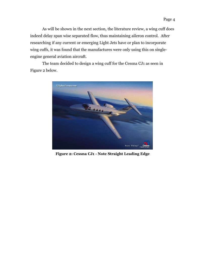
As will be shown in the next section, the literature review, a wing cuff does
indeed delay span wise separated flow, thus maintaining aileron control. After
researching if any current or emerging Light Jets have or plan to incorporate
wing cuffs, it was found that the manufactures were only using this on single-
engine general aviation aircraft.
The team decided to design a wing cuff for the Cessna CJ1 as seen in
Figure 2 below.
Figure 2: Cessna CJ1 - Note Straight Leading Edge

Page 5
2.0 Literature Review
Various papers were reviewed in order to gain a better understanding of
the problem and prior work pertaining to the group’s issue. There has been a
small amount of work done examining the addition of wing cuffs and other
leading edge modifications on general aviation aircraft. This section reviews the
documents examined in hopes to better understand the group’s design project.
The first document reviewed was an AIAA paper, AIAA-1988-4353, and is
listed as Reference 1 in the Appendix of this report. The document examined the
prediction of platform modification effects at high angles of attack. The figure
below shows a wing with the addition of a wing cuff exposed to some freestream
flow.
It can clearly be seen, that as the flow passes over the wing, the addition of
the cuff creates a secondary vortex normally not produce by a stock wing. The tip
vortex, which generally appears, can also be seen. This secondary vortex delays
the spanwise stall propagation over the wing. At high angles of attack, where the
stock portion of the wing is stalled, the flow over the outboard section of the wing
and consequently over the aileron, remains attached. This attached flow allows
aileron control even at high angles of attack.
Figure 3: Vortex Creation over Outboard
Wing Section

Page 6
The next paper reviewed was from the Journal of Aircraft and can be seen
in Reference 2 in the Appendix. The topic of this paper examined the stall
departure resistance as a result of a wing leading edge droop/slot modification.
Figure 4 below is similar to Figure 3 above.
This figure also shows the generation of a vortex as a direct result of the
leading edge modification. Disregarding the leading edge slot and the vortex
created by this, the addition of the leading edge droop, which is comparable to a
wing cuff, also creates a secondary vortex over the wing. As shown above, the
flow over the inboard section of the wing is very disturbed and separated while
the vortex created by the wing cuff prevents the stall from occurring over the
outboard section.
Tests were performed both in a wind tunnel and in real flight test of an
aircraft with and without wing modification. The wing modification had 2
changes to the chord of the wing. There was an extension of 2.57% and 0.77%
droop of the local chord and an extension of 2.44% and 1.62% droop to the local
chord. Each configuration was tested both for a free to roll apparatus and the
stall pattern at high angles of attack. The wind tunnel test showed that the vortex
created by the leading edge extension and droop caused the separated flow to not
propagate down the span and remain attached to the wing airfoil. A flight test
Figure 4: Flow Characteristics Resulting from
Leading Edge Modification

Page 7
was performed with the same condition as the wind-tunnel test. The flight test
used small yard tuffs to view attached and separated flow over the wing. The
tuffs of yarn were examined at high angles of attack for both configurations. The
leading edge extension and droop caused the separated flow to stop right at the
leading edge extension and remain attached. The paper concluded that the wing
leading edge modification significantly improved the stall departure resistance.
The full-scale flight test with the modified configuration demonstrated a gentle
and easily controlled stall for all types of stalls tested.
Reference 3 in the Appendix lists a SAE paper used during the design of
the wing cuff. This paper reviewed wing modification for increased spin
resistance on a general aviation aircraft. This study found that a segmented
leading edge device can increase the maximum angle of attack by 20 degrees and
increase roll control at these higher angles of attack. An outer wing drooped
leading edge results in a significant delay in wing-tip stall thus improving lateral
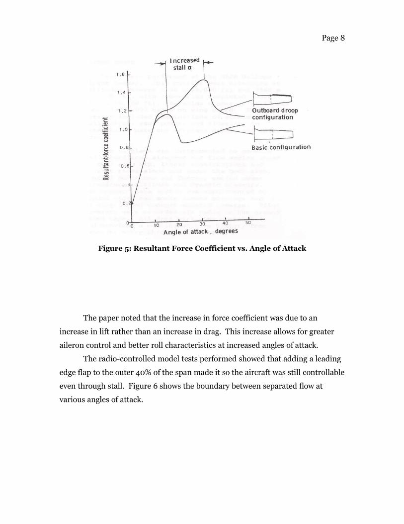
stability. Figure 5 below shows the resultant force coefficient, the addition of lift
and drag, as a function of angle of attack for both the basic configuration and a
wing with a wing droop.
Page 8
The paper noted that the increase in force coefficient was due to an
increase in lift rather than an increase in drag. This increase allows for greater
aileron control and better roll characteristics at increased angles of attack.
The radio-controlled model tests performed showed that adding a leading
edge flap to the outer 40% of the span made it so the aircraft was still controllable
even through stall. Figure 6 shows the boundary between separated flow at
various angles of attack.
Figure 5: Resultant Force Coefficient vs. Angle of Attack

Page 9
Reference 4 in the Appendix investigated the spin recovery ability of a low
speed aircraft with straight wings at various angles of attack and various engine
throttle settings for a wing with leading edge slats and compares it to a regular
airfoil. The purpose of the paper was to provide designers of small aircraft ways
to size the slot to aid in aircraft control near stall. The paper includes many
sketches of the tufts experiments performed which show the separated flow over
the airfoil and the effect of the slat. It is shown that the slats delay separation
over the region of the airfoil behind the slat. In addition, the slat increased CLmax.
The flow characteristics at various angles of attack can be viewed in Figure 7.
Figure 6: Separated Flow Boundary at Various
Angles of Attack

Page 10
Figure 7: Flow Characteristic Comparison
It can be seen that at approximately 17 degrees, the flow over the
unmodified wing is mostly disturbed and separated near the inboard section.
However, at the same angle of attack, the modified wing has smooth flow over the
outboard section. The modified wing still exhibits disturbed flow over the
inboard section, but over the aileron the flow is smooth. The flow remains
smooth over the outboard section of the wing until approximately 25 degrees,
which is much higher than the original wing configuration.
The final paper containing a plethora of useful information is listed as
Reference 5 in the Appendix. This paper was a NASA Technical Paper that
examined the effects of wing leading edge modifications on full-scale, low-wing
general aviation aircraft. It discusses tests performed on leading-edge
modifications in the Langley 30-60 foot wind tunnel. It examines different

Page 11
arrangements of leading edge droops and slat configurations. Some of the tests
were made to determine the control effectiveness and the effect of power. It was
found that the addition of a drooped leading edge on the outboard section of the
wing delayed tip stall to a very high angle of attack and resulted in a relatively
small drag penalty in cruise. Increases in lateral control were seen throughout
many angles of attack. Figure 8 shows both coefficient of lift and coefficient of
drag versus angle of attack.
The data points represented by circles on the plot were created using the
basic wing configuration in the paper. The other two sets of data points, squares
and diamonds, were created by testing modified wing configurations. The plot
shows that at high angles of attack, the modified wing configurations have a
much gentler stall and in some cases, level off around the stall location of the
unmodified wing. The coefficient of lift remains approximately 1.2 at angle of
Figure 8: Cl and Cd vs. Alpha

Page 12
attack up to 40 degrees. At this same location, the lift coefficient for the
unmodified wing, after first stalling, is approximately 0.9. Of special note is the
fact that with the addition of the leading edge modification throughout all angles
of attack, there is no or a negligible drag penalty.

Page 13
3.0 Introduction to Design Project
After completing the literature review, it was determined that the addition
of the wing cuff does create a secondary vortex, delaying the spanwise stall
propagation at high angles of attack. As mentioned previously, the emerging
market for light jets is a natural segue from single engine piston aircraft. The
design project was to design a wing cuff for use on the Cessna CJ1, as seen in
Figure 9 below, to help maintain roll control at high angles of attack.
Figure 9: Proposed Location of Wing Cuff on the CJ1

Page 14
4.0 Design Approach
The design outline below summarizes the tools used during the design
process. Although CMARC was a fast tool to use to show that the wing cuff does
create a vortex on top of the wing, it does not predict separation so it could not
fully capture the flow field for this analysis. Because of this, a FLUENT model
was created. Although this model also provided good visualizations, the team's
limited knowledge with FLEUNT made getting accurate computations difficult.
In the interest of time, a simplified model was developed to analyze the effect of
the wing cuff using only XFoil and MatLab.
1) Analyze wing cuff using CMARC
2) Create wing geometry in SolidWorks CAD package
a) Wing with no cuff - Aileron Deployed
b) Wing with no cuff - Aileron not Deployed
c) Wing with cuff - Aileron Deployed
d) Wing with cuff - Aileron not Deployed
3) Import CAD model into Gambit
4) Create mesh in Gambit
5) Run FLUENT for both stock and modified configurations
6) Calculate Cl for various airfoil sections with XFoil
7) Analyze root bending moment using MatLab with XFiol data

Page 15
4.1 CMARC:
The first analysis attempted utilized CMARC. However, this program does
not model separated flow, and therefore could only be used to demonstrate the
creation of a vortex due to the wing cuff. Figure 10 shows the wing geometry
used in the CMARC analysis. Figure 11 shows the vortex created at the location of
the cuff as well as the wing tip.
This simulation validated the vortex creation due to the addition of the
wing cuff as stated in the numerous papers examined during the literature
review. No conclusions could be drawn from the Cp distribution plots created
using CMARC due to the limited variation across the span of the wing.
Figure 11: CMARC Wing Wake
Figure 10: CMARC Wing Geometry

Page 16
4.2 Fluent
Based on experience from AAE 412, Introduction to Computational Fluid
Dynamics, a decision was made to use FLUNET as a means to show separated
flow over the wing models. The first step was to use SolidWorks CAD package to
model the CJ1 wing based on geometry obtained from Jane’s All the World’s
Aircraft. The CJ1 wing utilizes a NACA 23014 airfoil section across it's span.
Images of the model with and without the cuff are seen in Figure 12 below.
Figure 12: SolidWorks Model of CJ1 Stock Wing and Cuffed Wing
This file was exported as an *.iges file to be read into Gambit to create a
mesh around the wing. With limited overall knowledge of Gambit it was difficult
to create a mesh fine enough to capture boundary layer separation. The finest
grid created is shown in Figure 13.

Page 17
Figure 13: CJ1 Cuffed Wing FLUENT Grid
Figure 14 shows the grid of the wing and the symmetric boundary
condition at the root of the airfoil. These conditions allow for flow through the
boundary wall which prevents errors due to wall boundary layers.

Page 18
Two mesh files were created, one with the cuffed and one with the stock
wing design. The FLUENT calculations were iterated about 2000 times for each
case. Further research into FLUENT indicated that for the solution to converge
to reasonable results the calculations must be run for 10,000’s of iterations which
could take days to run using the available resources.
Although the results obtained from the FLUENT models are not
necessarily numerically correct, they do show trends that coincide with the
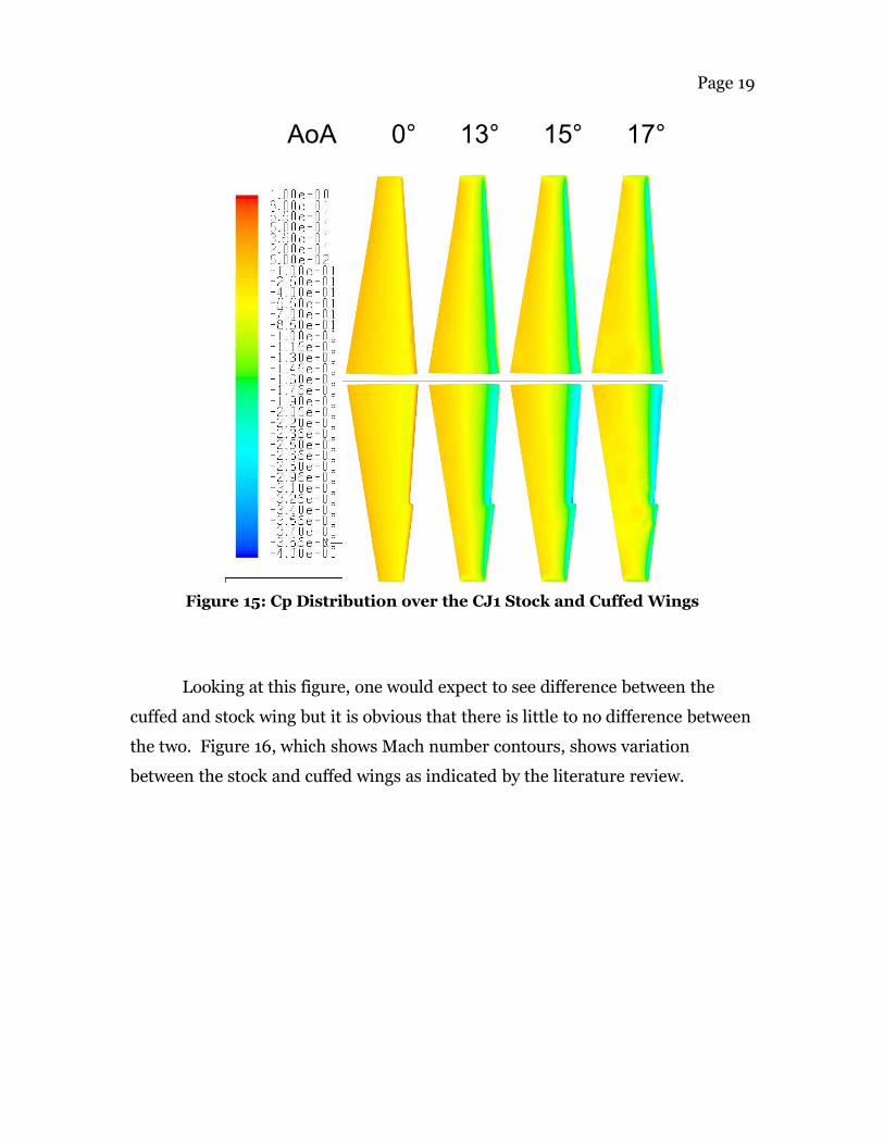
information found in the literature review. In Figure 15 is a contour of the
coefficient of pressure for the cuffed and stock wings.
Figure 14: FLUENT Grid Display of Symmetric Boundary Wall
Page 19
Figure 15: Cp Distribution over the CJ1 Stock and Cuffed Wings
Looking at this figure, one would expect to see difference between the
cuffed and stock wing but it is obvious that there is little to no difference between
the two. Figure 16, which shows Mach number contours, shows variation
between the stock and cuffed wings as indicated by the literature review.
AoA 0° 13° 15° 17°

Page 20
Figure 16: Mach Distribution over the CJ1 Stock and Cuffed Wings
At 16° angle of attack there is some considerable difference between the
cuffed and stock wings. The stock wing clearly shows that no vortices are created
over the wing, expect on the wing tip. Figure 16 also shows a vortex on the cuffed
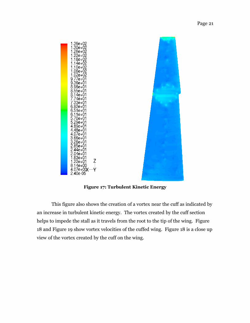
wing at the location of the discontinuity of the leading edge. Figure 17 shows
turbulent kinetic energy on the cuffed wing.
AoA 0° 13° 15° 17°
Page 21
This figure also shows the creation of a vortex near the cuff as indicated by
an increase in turbulent kinetic energy. The vortex created by the cuff section
helps to impede the stall as it travels from the root to the tip of the wing. Figure
18 and Figure 19 show vortex velocities of the cuffed wing. Figure 18 is a close up
view of the vortex created by the cuff on the wing.
Figure 17: Turbulent Kinetic Energy

Page 22
The red arrow demonstrates a vortex as the flow is going vertical at high
velocity. Directly after the cuff are rolling eddies created by the vortex. Figure 19
is a velocity vortex plot of the entire wing. This figure also shows the vortex
created by the wing cuff.
Figure 18: Velocity Vector at the Cuff

Page 23
Although FLUENT can show separated flow on a wing or an airfoil, it had
trouble showing the interaction of the vortex with the separated flow. The
FLUENT model did demonstrate that the literature was correct about the
creation of the vortex. Due to the fact that FLUENT was unable to show the
separated flow prior to the cuff and attached flow after the cuff, another form of
analysis was required. Thus the XFoil/MatLab analysis was used to estimate the
performance increase due to the wing cuff.
Figure 19: Velocity Vector of Cuffed Wing
Page 24
4.3 XFOIL/MatLab
The XFoil and MatLab analysis consisted of calculating the root bending
moment on the wing due to the total lift. This analysis assumes that the wing
geometry is the same as in the CMARC analysis shown in Figure 10. The total lift
on each wing section, the root and the cuff, was calculated by assuming constant
Cl across the span. The bending moment at the root was then assumed to be that
total lift value calculated multiplied by the distance from the root to the center of
the wing section. The root bending moment was calculated assuming the root
section is stalled and assuming the cuff section is attached. These two values
were then used to find a percent increase in bending moment. This increase in
bending moment corresponds to better roll control for the cuffed wing which
leads to the ability to prevent aircraft spin. The MatLab code used to perform the
root bending moment calculations can be seen in Appendix 7.3.
XFoil was used to calculate the Cl of an airfoil section for various angles of
attack. These numbers were taken as the coefficient of lift values for when the
flow is attached. Based on examination of experimental data from Abbott and
von Doenhoff, a separated Cl of 40% less than Cl max was assumed for separated
flow. Figure 20 shows the airfoil geometries used to calculate Cl. A curved
aileron configuration was used to ensure XFoil would accept the geometry
without error. The Cl results attained from XFoil and the 40% relation discussed
are shown in Table 1.

Page 25
Figure 20: Airfoil Geometry
Cl Root - Separated 1.0 (Abbott & von Doenhoff)
Cl Cuff - Aileron Nominal - Attached 1.69
Cl Cuff - Aileron Nominal - Separated 1.02
Cl Cuff - Aileron Up - Attached 0.81
Cl Cuff - Aileron Up - Separated 0.49
Cl Cuff - Aileron Down - Attached 1.96
Cl Cuff - Aileron Down - Separated 1.18
Table 1: Cl Values For Airfoils from Figure 20
Figure 21 shows the percent increase in root bending moment for the
aileron up configuration. The horizontal axis is the percent increase in chord
length of the cuff when compared to the root section. The vertical axis is the
percent of the total wing span that the wing cuff takes up. Figure 22 shows the
percent increase in root bending moment for the aileron down configuration.

Page 26

Page 27
Figure 23 shows the percent increase in platform area for the various
combinations of cuff size. Note that the percent increase in wing area directly
correlates to an increase in wing weight.
Figure 23: Platform Area Percent Increase

Page 28
5.0 Final Design
The cuff for the CJ1 was restricted to a 1% increase in platform area in
order to prevent a drastic increase in weight. Using this criterion along with the
size of the aileron as shown in Appendix 7.1, the cuff was sized using Figure 23.
Note that although the aileron on the CJ1 covers only 34% of the span, the cuff
was sized at 40% of the span to ensure laminar flow over the aileron. The design
cuff dimensions are shown in Table 2.
Platform Area Increase 1 %Chord Increase 3 %Span Size 40 %
Table 2: CJ1 Cuff Size
Using the defined cuff dimensions and referring to Figure 21 and Figure
22, the percent increase in root bending moment are shown in Table 3.
Aileron Up Aileron Down% Increase 33.3 48.5
Table 3: Cuffed Wing Root Bending Moment Increase
Note that the addition of the cuff increases the root bending moment for
both the aileron up and aileron down configurations by about 40%. This change
increases the roll control of the aircraft at high angles of attach and thus helps to
prevent spin.

Page 29
6.0 Conclusion
As was shown in the literature review and multiple design analysis a wing
cuff creates a vortex over the top of the wing which energizes the boundary layer
and prevents premature separation along the wing. The computational tools
available were all helpful in showing the vortex creation and comparing the
inboard and outboard wing sections. Perhaps a more experienced FLUENT user
could obtain results similar to the XFoil/MatLab analysis. It was shown that
since the flow remains attached over the aileron, it remains effective at larger
angles of attack where the root section of the wing has already separated. As seen
in the literature review, the addition of the wing cuff does not increase the drag
on the wing a noticeable amount. Although the MatLab simulation used would
have an altered Cl distribution with respect to a stock wing, the Cl distribution
could be held constant with the addition of the wing cuff if the wing was properly
tapered.
The opportunity to use multiple tools to demonstrate a particular
aerodynamic design was overall a great learning experience. Knowledge gained
throughout the semester in AAE415 and skills acquired in other classes were
applied to this design problem. Anytime one sees an airplane with a wing cuff
there is no doubt they will imagine a vortex flowing over the wing and hope that
when the inexperienced pilot gets himself into a bad situation, the wing cuff will
help him recover.
Page 30
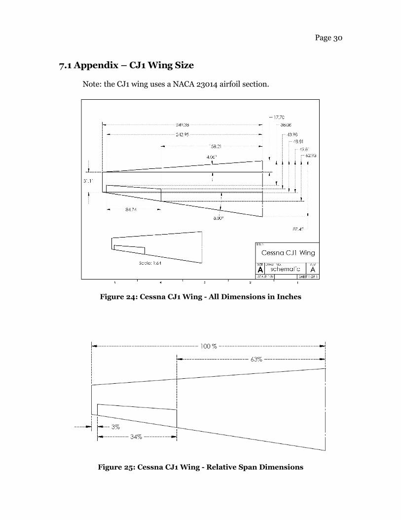
7.1 Appendix – CJ1 Wing Size
Note: the CJ1 wing uses a NACA 23014 airfoil section.
Figure 24: Cessna CJ1 Wing - All Dimensions in Inches
Figure 25: Cessna CJ1 Wing - Relative Span Dimensions

Page 31
7.2 Appendix – CMARC Input File
joined wing &BINP2 LSTINP=2, LSTOUT=1, LSTFRQ=0, LENRUN=0, LPLTYP=1, &END &BINP3 LSTGEO=1, LSTNAB=0, LSTWAK=0, LSTCPV=0, &END &BINP4 MAXIT=150, SOLRES=0.0005, &END &BINP5 NTSTPS=20, DTSTEP=.1 &END &BINP6 RSYM=0.0, RGPR=0.0, RFF=5.0, RCORE=0.008, RCOREW=0.0080, &END &BINP7 VINF=1, VSOUND=1116.0, &END &BINP8 ALDEG=10.0, AWDEG=0.0, THEDOT=0.0, PSIDOT=0.0, PHIDOT=0.0, &END &BINP8A PHIMAX=0.0, THEMAX=0.0, PSIMAX=0.0,
WRX=0.0, WRY=0.0, WRZ=0.0, &END &BINP8B DXMAX=0.0, DYMAX=0.0, DZMAX=0.0,
WTX=0.0, WTY=0.0, WTZ=0.000, &END &BINP9 CBAR=1., SREF=5.0, SSPAN=5.0, RMPX=0.25, RMPY=0.00, RMPZ=0.00, &END &BINP10 NORSET=0, NBCHGE=0, NCZONE=0, NCZPAN=0, CZDUB=0.0, VREF=00.0, &END &BINP11 NORPCH=0, NORF=0, NORL=0,
NOCF=0, NOCL=0, VNORM=0.0, &END &BINP12 KPAN=0, KSIDE=0, NEWNAB=0, NEWSID=0, &END &BINP13 NBLIT = 0, &END &ASEM1 ASEMX=0.00, ASEMY=0.00, ASEMZ=0.00, ASCAL=1.00, ATHET=0.00, NODEA=5, &END &COMP1 COMPX=0.0000, COMPY=0.0000, COMPZ= 0.0000, CSCAL= 1.000, CTHET= 0.0, NODEC=5, &END
&PATCH1 IREV=0, IDPAT=1, MAKE=0, KCOMP=1, KASS=1, &END WING root bottom &SECT1 STX=0.000, STY=0.000, STZ=0.000, SCALE=1, ALF=0.0, THETA=0.0, INMODE=4, TNODS=0, TNPS=30, TINTS=0, &END 1 0 -0.0015 0.9992 0 -0.0016 0.9742 0 -0.0051 0.9492 0 -0.0084 0.9242 0 -0.0116 0.8992 0 -0.0148 0.8743 0 -0.0178 0.8493 0 -0.0207 0.8243 0 -0.0235 0.7993 0 -0.0263 0.7494 0 -0.0314 0.6994 0 -0.0362 0.6495 0 -0.0405 0.5995 0 -0.0444 0.5495 0 -0.0479 0.4996 0 -0.0507 0.3997 0 -0.0544 0.2998 0 -0.0545 0.1998 0 -0.0492 0.15 0 -0.044 0.1249 0 -0.0409 0.0999 0 -0.0376 0.0749 0 -0.0341 0.05 0 -0.0299 0.0375 0 -0.0273 0.025 0 -0.0238 0.0125 0 -0.0185 0.005 0 -0.0127 0.002 0 -0.0085 0 0 0.0005 &BPNODE TNODE=3, TNPC=15, TINTC=0, &END
&SECT1 STX=.00, STY=4.000, STZ=0., SCALE=1.00, ALF=0.0, THETA=0.0,

Page 32
INMODE=0, TNODS=3, TNPS=30, TINTS=0, &END
&PATCH1 IREV=0, IDPAT=1, MAKE=0, KCOMP=1, KASS=1, &END WING root top &SECT1 STX=0.000, STY=0.000, STZ=0.000, SCALE=1, ALF=0.0, THETA=0.0, INMODE=4, TNODS=0, TNPS=30, TINTS=0, &END 0 0 0.0005 0.002 0 0.0097 0.005 0 0.0157 0.0125 0 0.0256 0.025 0 0.0371 0.0375 0 0.0459 0.05 0 0.053 0.0749 0 0.0638 0.0999 0 0.0716 0.1249 0 0.077 0.1499 0 0.0807 0.1998 0 0.0846 0.2998 0 0.0855 0.3997 0 0.081 0.4996 0 0.0728 0.5495 0 0.0678 0.5995 0 0.0621 0.6495 0 0.056 0.6994 0 0.0494 0.7494 0 0.0425 0.7993 0 0.0351 0.8243 0 0.0313 0.8493 0 0.0274 0.8743 0 0.0233 0.8992 0 0.0192 0.9242 0 0.015 0.9492 0 0.0107 0.9742 0 0.0062 0.9992 0 0.0016 1 0 0.0015 &BPNODE TNODE=3, TNPC=15, TINTC=0, &END &SECT1 STX=.00, STY=4, STZ=0., SCALE=1.00, ALF=0.0, THETA=0.0, INMODE=0, TNODS=3, TNPS=30, TINTS=0, &END
&PATCH1 IREV=0, IDPAT=1, MAKE=0, KCOMP=1, KASS=1, &END WING tip bottom &SECT1 STX=0.000, STY=4.000, STZ=0.000, SCALE=1.0, ALF=0.0, THETA=0.0, INMODE=4, TNODS=0, TNPS=20, TINTS=0, &END 1 0 -0.0015 0.9992 0 -0.0016 0.9742 0 -0.0051 0.9492 0 -0.0084 0.9242 0 -0.0116 0.8992 0 -0.0148 0.8743 0 -0.0178 0.8493 0 -0.0207 0.8243 0 -0.0235 0.7993 0 -0.0263 0.7494 0 -0.0314 0.6994 0 -0.0362 0.6495 0 -0.0405 0.5995 0 -0.0444 0.5495 0 -0.0479 0.4996 0 -0.0507 0.3997 0 -0.0544 0.2998 0 -0.0545 0.1698 0 -0.0492
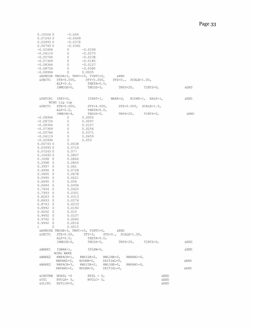
Page 33
0.10506 0 -0.044 0.07243 0 -0.0409 0.03993 0 -0.0376 0.00743 0 -0.0341 -0.02494 0 -0.0299 -0.04119 0 -0.0273 -0.05744 0 -0.0238 -0.07369 0 -0.0185 -0.08344 0 -0.0127 -0.08734 0 -0.0085 -0.08994 0 0.0005 &BPNODE TNODE=3, TNPC=15, TINTC=0, &END &SECT1 STX=0.000, STY=5.000, STZ=0., SCALE=1.00, ALF=0.0, THETA=0.0, INMODE=0, TNODS=3, TNPS=20, TINTS=0, &END
&PATCH1 IREV=0, IDPAT=1, MAKE=0, KCOMP=1, KASS=1, &END WING tip top &SECT1 STX=0.000, STY=4.000, STZ=0.000, SCALE=1.0, ALF=0.0, THETA=0.0, INMODE=4, TNODS=0, TNPS=20, TINTS=0, &END -0.08994 0 0.0005 -0.08734 0 0.0097 -0.08344 0 0.0157 -0.07369 0 0.0256 -0.05744 0 0.0371 -0.04119 0 0.0459 -0.02494 0 0.053 0.00743 0 0.0638 0.03993 0 0.0716 0.07243 0 0.077 0.10493 0 0.0807 0.1698 0 0.0846 0.2998 0 0.0855 0.3997 0 0.081 0.4996 0 0.0728 0.5495 0 0.0678 0.5995 0 0.0621 0.6495 0 0.056 0.6994 0 0.0494 0.7494 0 0.0425 0.7993 0 0.0351 0.8243 0 0.0313 0.8493 0 0.0274 0.8743 0 0.0233 0.8992 0 0.0192 0.9242 0 0.015 0.9492 0 0.0107 0.9742 0 0.0062 0.9992 0 0.0016 1 0 0.0015 &BPNODE TNODE=3, TNPC=15, TINTC=0, &END &SECT1 STX=0.00, STY=5, STZ=0., SCALE=1.00, ALF=0.0, THETA=0.0, INMODE=0, TNODS=5, TNPS=20, TINTS=0, &END
&WAKE1 IDWAK=1, IFLXW=0, &END WING WAKE
&WAKE2 KWPACH=1, KWSIDE=2, KWLINE=0, KWPAN1=0, KWPAN2=0, NODEW=0, INITIAL=0, &END
&WAKE2 KWPACH=3, KWSIDE=2, KWLINE=0, KWPAN1=0, KWPAN2=0, NODEW=5, INITIAL=0, &END
&ONSTRM NONSL =0 KPSL = 0, &END &VS1 NVOLR= 0, NVOLC= 0, &END &SLIN1 NSTLIN=0, &END

Page 34
7.3 Appendix – MatLab Code
close allclear allclc
%assume that root is stalled and tip is not (tip is stalled in stock%numbers for comparison). also assume that aileron has no effect after%stall.
%-----------------------------------% wing at 14 deg% root is stalledClr_sep = 1.016; %guessCltan_at = 1.6936;Cltan_sep = 1.016; %guessCltau_at = 0.8127;Cltau_sep = 0.4876; %guessCltad_at = 1.9585;Cltad_sep = 1.1751; %guess%-----------------------------------
bw = 6.35;cr = 1.505;
rho = 1.23;V = 57.85;
gammaA = 0:.01:.5; %fraction of total span that tip coversbetaA = 1:.01:1.2; %tip chord fraction of root chord
found = 0;
areainc = 1;spanfrac = .4;
for idx1 = 1:1:length(gammaA) gamma = gammaA(idx1); for idx2 = 1:1:length(betaA) beta = betaA(idx2); S_percinc(idx1,idx2) = (gamma*beta-gamma)*100; Mr_cuff_au(idx1,idx2) = 0.25*bw^2*rho*V^2*cr*((1-gamma)^2*Clr_sep + (2-gamma)*gamma*beta*Cltau_at); Mr_cuff_ad(idx1,idx2) = 0.25*bw^2*rho*V^2*cr*((1-gamma)^2*Clr_sep + (2-gamma)*gamma*beta*Cltad_at); Mr_cuff_an(idx1,idx2) = 0.25*bw^2*rho*V^2*cr*((1-gamma)^2*Clr_sep + (2-gamma)*gamma*beta*Cltan_at); Mr_stock_au(idx1,idx2) = 0.25*bw^2*rho*V^2*cr*((1-gamma)^2*Clr_sep + (2-gamma)*gamma*1*Cltau_sep); Mr_stock_ad(idx1,idx2) = 0.25*bw^2*rho*V^2*cr*((1-gamma)^2*Clr_sep + (2-gamma)*gamma*1*Cltad_sep);

Page 35
Mr_stock_an(idx1,idx2) = 0.25*bw^2*rho*V^2*cr*((1-gamma)^2*Clr_sep + (2-gamma)*gamma*1*Cltan_sep); Mr_delta_au(idx1,idx2) = abs(Mr_cuff_au(idx1,idx2) - Mr_stock_au(idx1,idx2))/Mr_stock_au(idx1,idx2)*100; Mr_delta_ad(idx1,idx2) = abs(Mr_cuff_ad(idx1,idx2) - Mr_stock_ad(idx1,idx2))/Mr_stock_ad(idx1,idx2)*100; Mr_delta_an(idx1,idx2) = abs(Mr_cuff_an(idx1,idx2) - Mr_stock_an(idx1,idx2))/Mr_stock_an(idx1,idx2)*100;
if gamma == spanfrac if S_percinc(idx1,idx2) > areainc & found == 0 found = 1; idxf1 = idx1; idxf2 = idx2; end end endend
disp('At Design Point')
fprintf('Platform Area Increase: %0.3f Percent \n',areainc)fprintf('Cuff Percent of Span: %0.3f Percent\n',(spanfrac)*100)fprintf('Cuff Percent Increase of Chord: %0.3f Percent\n',(betaA(idxf2)-1)*100)
fprintf('Root Bending Moment cuff au: %0.0f \n',Mr_cuff_au(idxf1,idxf2))fprintf('Root Bending Moment cuff ad: %0.0f \n',Mr_cuff_ad(idxf1,idxf2))fprintf('Root Bending Moment cuff an: %0.0f \n',Mr_cuff_an(idxf1,idxf2))
fprintf('Root Bending Moment stock au: %0.0f \n',Mr_stock_au(idxf1,idxf2))fprintf('Root Bending Moment stock ad: %0.0f \n',Mr_stock_ad(idxf1,idxf2))fprintf('Root Bending Moment stock an: %0.0f \n',Mr_stock_an(idxf1,idxf2))
fprintf('Root Bending Moment Percent Increase au: %0.3f \n',Mr_delta_au(idxf1,idxf2))fprintf('Root Bending Moment Percent Increase ad: %0.3f \n',Mr_delta_ad(idxf1,idxf2))fprintf('Root Bending Moment Percent Increase an: %0.3f \n',Mr_delta_an(idxf1,idxf2))
figurepcolor((betaA-1).*100,100.*gammaA,Mr_delta_au)lighting phongshading interpcolorbarylabel('Unserparated Section Length (% Total Span)')xlabel('Unserparated Section Chord Increase (% Root Chord)')title('Percent Increase in Root Bending Moment Aileron Up')axis square

Page 36
figurepcolor((betaA-1).*100,100.*gammaA,Mr_delta_an)lighting phongshading interpcolorbarylabel('Unserparated Section Length (% Total Span)')xlabel('Unserparated Section Chord Increase (% Root Chord)')title('Percent Increase in Root Bending Moment Aileron Nominal')axis square
figurepcolor((betaA-1).*100,100.*gammaA,Mr_delta_ad)lighting phongshading interpcolorbarylabel('Unserparated Section Length (% Total Span)')xlabel('Unserparated Section Chord Increase (% Root Chord)')title('Percent Increase in Root Bending Moment Aileron Down')axis square
figurepcolor((betaA-1).*100,100.*gammaA,S_percinc)lighting phongshading interpcolorbarylabel('Unserparated Section Length (% Total Span)')xlabel('Unserparated Section Chord Increase (% Root Chord)')title('Percent Increase in Platform Area')axis square

Page 37
7.4 Appendix - References
1. AIAA-1988-4353 - Prediction of platform modification effects at high angles of attack. AIAA Atmospheric Flight Mechanics Conference, Minneapolis, MN, Aug. 15-17, 1988, Technical Papers (A88-50576 21-01). Washington, DC, American Institute of Aeronautics and Astronautics, 1988, p. 217-222.
2. H. M. Ross, L. P. Yip, J. N. Perkins, R. J. Vess and D. B. Owens; “Wing Leading-Edge Droop/Slot Modification for the stall Departure Resistance,” Journal of Aircraft. Vol. 28. N 7. Pg 436 – 442
3. Stough, H. Paul, DiCarlo, Daniel J., Stewart, Eric C., “Wing Modification for Increased Spin Resistance”, NASA Langley Research Center, SAE Technical Paper Series, Paper 830720, Business Aircraft Meeting & Exposition, Wichita, Kansas, April 12-15, 1983.
4. NACA TN 2948 – Investigation of the Lateral Control Near the Stall Flight Investigation With a Light High-Wing Monoplane Tested With Various Amounts of Washout and Various Lengths of Leading-Edge Slot
5. NASA TP-2011, 1982 – Effects of Wing-Leading Edge Modification on a Full-Scale, Low-Wing General Aviation Airplane
6. Jackson, P. (2001). Jane's All the World's Aircraft. Alexandria, VA. Jane'sInformation Group Inc.
7. Abbott, I., von Doenhoff, A., (1959). Theory of Wing Sections. New York, NY.Dover Publications Inc.
8. http://www.cirrusdesign.com
9. Underland, Gene. [email protected]. “Re:Cirrus?”. 26 Oct 2004.