aaf international installation, operation and maintenance manual · 2015-11-13 · this document...
TRANSCRIPT

T H E W O R L D L E A D E R I N C L E A N A I R S O L U T I O N S
AAF® INTERNATIONAL
INSTALLATION, OPERATIONAND MAINTENANCE MANUAL
RotoClone™ W

2 RotoClone® W
© 2015 American Air Filter Company, Inc. Any use of the text or images this document contains, without permission of American Air Filter Company, Inc., is prohibited. RotoClone, AAF, REDClean, REDFiltration, and Reliable Efficient Durable are registered trademarks of American Air Filter Company, Inc. d/b/a AAF International.
TO ORDER SPARE & REPLACEMENT PARTS
Call 1-800-477-1214
Email: [email protected]
Parts Sales Power & Industrial
AAF International 9920 Corporate Campus Drive
Suite 2200 Louisville, KY 40223-5000
USA
Internet: http://www.AAFParts.com

3 RotoClone® W
© 2015 American Air Filter Company, Inc. Any use of the text or images this document contains, without permission of American Air Filter Company, Inc., is prohibited. RotoClone, AAF, REDClean, REDFiltration, and Reliable Efficient Durable are registered trademarks of American Air Filter Company, Inc. d/b/a AAF International.
TABLE OF CONTENTS
1 INTRODUCTION ........................................................................................................................... 5
2 SAFETY .............................................................................................................................................. 5
2.1 Safety statement ................................................................................................................. 5 2.2 Safe working practices and staff training ............................................................ 5 2.3 Dust explosions .................................................................................................................... 6
2.3.1 NFPA 654 and referenced codes and standards .......................................................................... 7
2.3.2 Other requirements ............................................................................................................................................ 8
2.4 Electrical hazards ................................................................................................................ 9 2.5 Rotating equipment ........................................................................................................... 9 2.6 Safety guards ........................................................................................................................ 9
3 GENERAL PRODUCT INFORMATION .............................................................................. 10
3.1 Description ............................................................................................................................ 10 3.2 Purpose and intended use ........................................................................................... 10 3.3 Normal Operation .............................................................................................................. 10 3.4 Sizes .......................................................................................................................................... 13 3.5 Filter elements .................................................................................................................... 13 3.6 Weights ................................................................................................................................... 14 3.7 Food Quality RotoClone W ........................................................................................... 14 3.8 Range Hood and FM Controls ..................................................................................... 15
4 PRODUCT SHIPMENT .............................................................................................................. 16
4.1 How the product ships ................................................................................................... 16 4.2 Items that ship separately .......................................................................................... 16
5 PRODUCT RECEIPT AT THE DESIGNATED DELIVERY POINT .......................... 16
5.1 Responsibilities of the customer or the customer’s agent ....................... 16 5.2 Receiving ................................................................................................................................ 16 5.3 Inspection on arrival ....................................................................................................... 16 5.4 Damaged goods .................................................................................................................. 17 5.5 Missing goods ...................................................................................................................... 17
6 UNLOADING AND HANDLING ............................................................................................ 17
6.1 Unloading ............................................................................................................................... 17 6.2 Handling.................................................................................................................................. 18 6.3 Rigging and hoisting instructions ........................................................................... 18
7 STORAGE AND PROTECTION .............................................................................................. 18
8 SITE PREPARATION ................................................................................................................ 20

4 RotoClone® W
© 2015 American Air Filter Company, Inc. Any use of the text or images this document contains, without permission of American Air Filter Company, Inc., is prohibited. RotoClone, AAF, REDClean, REDFiltration, and Reliable Efficient Durable are registered trademarks of American Air Filter Company, Inc. d/b/a AAF International.
8.1 Locating equipment ......................................................................................................... 20 8.2 Foundations .......................................................................................................................... 20
9 ASSEMBLY AND INSTALLATION ...................................................................................... 20
9.1 Introduction ......................................................................................................................... 20 9.2 Assembling and installing the structure ............................................................. 21
9.2.1 Arrangement A ..................................................................................................................................................... 21
9.2.2 Arrangement D ..................................................................................................................................................... 22
9.2.3 Bearings ..................................................................................................................................................................... 24
9.2.4 Drive ............................................................................................................................................................................. 25
9.2.5 Electrical Connections ..................................................................................................................................... 25
9.2.6 Water connections ............................................................................................................................................. 26
9.2.7 Ductwork Installation ...................................................................................................................................... 32
10 START-UP & OPERATION ..................................................................................................... 33
10.1 Start-up checklist .............................................................................................................. 33
11 MAINTENANCE ........................................................................................................................... 34
11.1 Record Keeping .................................................................................................................. 34 11.2 Lubrication ............................................................................................................................ 34 11.3 Nozzles and Strainer ....................................................................................................... 35 11.4 RotoClone Inlet (Arr. A) ................................................................................................ 35 11.5 Pre-cleaner Inlet (Arr. D) ............................................................................................ 36 11.6 RotoClone Impeller .......................................................................................................... 36 11.7 Drains ....................................................................................................................................... 36 11.8 Emergency Overflow (Arr. D only) ......................................................................... 37 11.9 Shaft Seal ............................................................................................................................... 37 11.10 Replacement of Shaft, Impeller or Water Cone .................................... 38
12 TROUBLESHOOTING................................................................................................................ 41
12.1 Water Entrainment ........................................................................................................... 41 12.2 Dust Entrainment .............................................................................................................. 42 12.3 Start/Stop Issues ............................................................................................................. 42
13 RECOMMENDED SPARE PARTS ......................................................................................... 43

5 RotoClone® W
© 2015 American Air Filter Company, Inc. Any use of the text or images this document contains, without permission of American Air Filter Company, Inc., is prohibited. RotoClone, AAF, REDClean, REDFiltration, and Reliable Efficient Durable are registered trademarks of American Air Filter Company, Inc. d/b/a AAF International.
1 INTRODUCTION This document contains the information necessary to properly receive,
assemble, install, operate, and maintain the AAF RotoClone® W filter system and
filters. The purchaser, installer, and operator of the filter system MUST read and comply with this document in its entirety prior to installation of the equipment and
its operation. Failure to comply with the requirements of this manual may void the product warranty. The information and guidelines contained in this
manual are not exhaustive, and additional or alternative precautions, measures, training, etc. may be needed depending on the specific circumstances.
CAUTION
These instructions are specific to the AAF RotoClone® W filter system and
filters. All ancillary tasks including, but not limited to, electrical and
mechanical work, equipment handling, and safety procedures must be performed in accordance with industry accepted practice and all relevant
local, state, and federal government codes, laws, and policies.
2 SAFETY 2.1 Safety statement
The air cleaning equipment supplied by AAF International ranges from very
large multiple-component assemblies which require significant and complex, rigging, handling and assembly on-site, to small compact assemblies that are
easily handled and maneuvered. In addition to size, many of the dust collectors will require electrical connections, compressed air connections, and will feature
high speed rotating equipment.
At all times, when dealing with industrial equipment such as dust collection equipment personnel safety must be the highest priority of all involved, from
riggers, installers, operators, users, and maintenance personnel. Those responsible on-site shall review the details of the equipment beforehand and
develop a plan for dealing with all stages of the installation from receipt of the equipment on-site to start-up, commissioning, and hand-over. All applicable
health, safety, and environmental (“HSE”) rules, regulations and legislation shall
be fully complied with at all times. 2.2 Safe working practices and staff training
AAF International is fully committed to the safety of its employees and those of its customers. In this spirit the following guidelines are offered for the
consideration of those responsible:

6 RotoClone® W
© 2015 American Air Filter Company, Inc. Any use of the text or images this document contains, without permission of American Air Filter Company, Inc., is prohibited. RotoClone, AAF, REDClean, REDFiltration, and Reliable Efficient Durable are registered trademarks of American Air Filter Company, Inc. d/b/a AAF International.
All personnel shall receive safety training specific to the site, the task, and
the conditions under which the work will be conducted.
All personnel shall be equipped with appropriate safety apparel and equipment, such as clothing, footwear, hard-hats, gloves, ear protection, eye
protection, and safety harness.
All personnel involved in any stage of the process shall have been trained for the tasks in which they will be involved and at all times shall be under the direct
supervision of experienced supervisors and managers.
All personnel shall be equipped with appropriate tools and equipment to safely and efficiently complete their task.
Adequate lighting shall be supplied at all times while work is being
conducted.
A work perimeter shall be set up to define the limits of the area within which
the work will be conducted and outside which there will be no threat to the safety of personnel or plant. The perimeter shall be taped-off and marked appropriately
to prevent accidental ingress of uninvolved personnel or equipment. When the work area impedes into existing access ways or traffic routes for which no practical
alternative is available, barriers, wardens and flaggers shall be employed to safely control crossing traffic and personnel.
At any time only those personnel directly involved in completing the task at
hand shall be allowed within the work perimeter. 2.3 Dust explosions
By its very nature the RotoClone® W is intended to be used to capture
airborne particulate matter, otherwise known as dust.
Many dusts have the potential to be explosive. Dust explosions constitute a serious industrial hazard and may result in death, serious injury, and devastating
property damage. It is the responsibility of the user to identify the nature of the dust generated during any process or activity, whether or not it poses an explosive
hazard, and to properly mitigate this hazard.
Except as otherwise expressly provided in writing, AAF makes no representation or warranty in connection with explosion hazard equipment,

7 RotoClone® W
© 2015 American Air Filter Company, Inc. Any use of the text or images this document contains, without permission of American Air Filter Company, Inc., is prohibited. RotoClone, AAF, REDClean, REDFiltration, and Reliable Efficient Durable are registered trademarks of American Air Filter Company, Inc. d/b/a AAF International.
including, but not limited to, the necessity or effectiveness of explosion hazard
equipment or to the design, installation, operation, and performance of such equipment.
The basic standards for dealing with explosive dust applications are
published by the National Fire Protection Agency (“NFPA”). The user shall be fully conversant with the provisions of the particular codes and standards that apply to
the specific application and equipment used, and shall comply in full with all of the requirements of the applicable codes and standards.
2.3.1 NFPA 654 and referenced codes and standards
The owner shall review and comply with NFPA 654: Standard for the
Prevention of Fire and Dust Explosions from the Manufacturing, Processing, and Handling of Combustible Particulate Solids, and those other
documents referenced therein. NFPA 654 pertains to “all phases of manufacturing, processing, blending, conveying, repackaging, and handling of combustible
particulate solids or hybrid mixtures, regardless of concentration or particle size, where the materials present a fire or explosion hazard”. The purpose of the
standard “is to prescribe technical requirements for safety to life and property from fire and explosion and to minimize the resulting damage from a fire or
explosion”. The user shall be fully conversant with the provisions of NFPA 654 and shall comply in full with all of its requirements and those of all applicable
referenced codes and standards.
Note that NFPA 654 does not apply to the specific applications or materials
covered by the following documents unless specifically referenced by those documents. Review this list to determine if any of these codes and standards apply
to the particular use for which the RotoClone® W will be employed. If such is the
case the appropriate documents shall be reviewed and complied with in full.
NFPA 30B, Code for the Manufacture and Storage of Aerosol Products, 2015
edition.
NFPA 33, Standard for Spray Application Using Flammable or Combustible Materials, 2011 edition.
NFPA 61, Standard for the Prevention of Fires and Dust Explosions in
Agricultural and Food Processing Facilities, 2013 edition.
8 RotoClone® W
© 2015 American Air Filter Company, Inc. Any use of the text or images this document contains, without permission of American Air Filter Company, Inc., is prohibited. RotoClone, AAF, REDClean, REDFiltration, and Reliable Efficient Durable are registered trademarks of American Air Filter Company, Inc. d/b/a AAF International.
NFPA 85, Boiler and Combustion Systems Hazards Code, 2015 edition.
NFPA 120, Standard for Fire Prevention and Control in Coal Mines, 2015
edition.
NFPA 400, Hazardous Materials Code, 2016 edition. NFPA 484, Standard for Combustible Metals, 2015 edition.
NFPA 495, Explosive Materials Code, 2013 edition.
NFPA 655, Standard for Prevention of Sulfur Fires and Explosions, 2012 edition.
NFPA 664, Standard for the Prevention of Fires and Explosions in Wood
Processing and Woodworking Facilities, 2012 edition.
NFPA 1124, Code for the Manufacture, Transportation, Storage, and Retail Sales of Fireworks and Pyrotechnic Articles, 2013 edition.
NFPA 1125, Code for the Manufacture of Model Rocket and High Power
Rocket Motors, 2012 edition.
2.3.2 Other requirements
The use of a dust collector for the collection of explosive dust is only one part of a safe dust prevention and mitigation program. Dust shall not be allowed to
accumulate or build up on the surfaces of the dust collector, on the air intakes or in the surrounding area. The owner’s attention is directed particularly to the
“Housekeeping” chapters in NFPA 654 (Chapter 8 in the 2013 edition) or NFPA 484 (Chapter 7 in the 2015 edition). If any of the other codes and standards
referenced above apply consult the appropriate chapters in those documents.
The editions referenced here were current at the time of writing. Be aware
that they may have changed. When referring to NFPA standards the user shall ensure that they are working with the most current edition.
For information on NFPA® standards, go to http://www.nfpa.org/ . NFPA
provides free on-line read-only access to its codes and standards. Standards may also be purchased.

9 RotoClone® W
© 2015 American Air Filter Company, Inc. Any use of the text or images this document contains, without permission of American Air Filter Company, Inc., is prohibited. RotoClone, AAF, REDClean, REDFiltration, and Reliable Efficient Durable are registered trademarks of American Air Filter Company, Inc. d/b/a AAF International.
2.4 Electrical hazards
Before doing any work on the AAF equipment make sure that all potential electrical hazards have been identified and that all electric current connected to
the equipment, and to any connected or associated equipment, has been properly disconnected and securely locked-out to prevent accidental reconnection prior to
completion of the work. All electrical work shall be done in full accordance with the current edition of NFPA 70, the National Electrical Code, and all other applicable
laws, rules, and regulations. All electrical work shall be performed by a licensed electrician. Only original AAF parts shall be used as replacements for ongoing
maintenance and repair.
2.5 Rotating equipment The RotoClone W acts as a dust collector and as a fan. The impeller may
rotate at nominal speeds approaching 3600 rpm and has the potential to cause severe injury. The collector’s impeller can be accessed through the collector from
the air inlet if the ductwork is removed, from the outside of the collector through
the collector discharge, and through various access panels. All due care should be exercised to avoid any contact with the operating collector’s impeller. Under no
circumstances should the collector ever be allowed to operate when any of the access panels on the dust collector have been removed. The fan must be
disconnected and locked out prior to the performance of any maintenance work, see paragraph 2.4.
2.6 Safety guards
The dust collector housing prevents access to the impeller blades. All access panels and the inlet duct shall remain bolted in place while the collector is
operating. Prior to the removal of any access panels, the electrical power to the collector shall be disconnected and locked out, see paragraphs 2.4 and 2.5.
After electrical power is disconnected, the impeller will continue to rotate for
a period of time before coasting to a stop.
Multiple outlet options are available at the outlet of the RotoClone W. These
outlet options are bolted to the outlet flange of the collector. Under no circumstances should these be removed while the collector is in operation or when
there is electrical power connected to the dust collector.

10 RotoClone® W
© 2015 American Air Filter Company, Inc. Any use of the text or images this document contains, without permission of American Air Filter Company, Inc., is prohibited. RotoClone, AAF, REDClean, REDFiltration, and Reliable Efficient Durable are registered trademarks of American Air Filter Company, Inc. d/b/a AAF International.
3 GENERAL PRODUCT INFORMATION 3.1 Description
The RotoClone W is a complete dust collector. It comprises a combination
fan and dust collector in a single compact device. Dust is separated from the airstream and the concentrated material is continuously discharged in a slurry
form. The RotoClone W can be applied in a variety of applications involving the collection of dry, damp, wet, or sticky dusts and where space is limited. The
distinguishing features of the RotoClone W are the combination of multiple high
power water sprays, special blade design, and dynamic precipitation.
The RotoClone W has been designed to operate automatically and requires very little maintenance. However, as is the case with any mechanical equipment, it
should be operated, and regularly maintained and serviced in accordance with these instructions to ensure long life and trouble free performance and use. 3.2 Purpose and intended use
The RotoClone W is a wet dust collector that is intended to be used for dust
collection. Typical product applications include mining, coal handling, food
processing, chemical handling, and general nuisance dusts. 3.3 Normal Operation
Dust laden air enters the RotoClone W where it is wetted by a fine conical water spray. The water and the dust, being heavier than air, impinge on the
blades of the impeller which are covered by a flowing water film which is sprayed separately onto and covers all blade surfaces. The water and dust are directed into
the water cone by the special blade design and the centrifugal force generated by
the rotating impeller. The mixture of dust and water forms a slurry which is emitted from the collector through the sludge chute and also from the drain in the
bottom of the RotoClone expansion chamber.
Similar to a fan, the rotating impeller and blades impart energy to the cleaned air, which being lighter than the water and dust, is discharged in front of
the water cone and continues to the clean air outlet.

11 RotoClone® W
© 2015 American Air Filter Company, Inc. Any use of the text or images this document contains, without permission of American Air Filter Company, Inc., is prohibited. RotoClone, AAF, REDClean, REDFiltration, and Reliable Efficient Durable are registered trademarks of American Air Filter Company, Inc. d/b/a AAF International.
Arrangement A
The RotoClone W Arrangement A is recommended for the collection of airborne granular dusts and mist up to loadings of 2 grains per cubic foot of inlet
air.

12 RotoClone® W
© 2015 American Air Filter Company, Inc. Any use of the text or images this document contains, without permission of American Air Filter Company, Inc., is prohibited. RotoClone, AAF, REDClean, REDFiltration, and Reliable Efficient Durable are registered trademarks of American Air Filter Company, Inc. d/b/a AAF International.
Arrangement D
The RotoClone W Arrangement D is designed to collect heavy concentrations of airborne granular dust up to loadings of 10 grains per cubic foot of inlet air. The
Arrangement D is equipped with an integral wet centrifugal pre-cleaner, which removes a high percentage of the incoming dust from the airstream. The
differential pressure in the wet pre-cleaner section is approximately twice the

13 RotoClone® W
© 2015 American Air Filter Company, Inc. Any use of the text or images this document contains, without permission of American Air Filter Company, Inc., is prohibited. RotoClone, AAF, REDClean, REDFiltration, and Reliable Efficient Durable are registered trademarks of American Air Filter Company, Inc. d/b/a AAF International.
value of the inlet velocity pressure for a RotoClone Arrangement A of the same
size. Collected dust and water are continuously discharged as a slurry through a single hopper drain. 3.4 Sizes
The RotoClone W Arrangement A is available in 12 sizes and the RotoClone
W Arrangement D is available in 7 sizes as outlined in the table below. The table also shows the inlet dust load range for each Arrangement and the airflow range
from the smallest to largest size. The RotoClone W Arrangement A sizes represent
the inlet diameter of the collector in inches (1 inch = 25.4 mm), e.g. the Size 12 has a 12 inch inlet diameter. See 3.6 for a listing of sizes with weights.
Arrangement
*
Inlet Dust Loading Sizes
Offered*
Airflow Range (Depending on
Size)*
Grains/ft3 mg/m3 ft3/ minute m3/ hour
A 0 to 2 0 to 4576 12.0 1000 to 50,000
1699 to 84950
D 0 to 10 0 to
22,884 7.0
1000 to 15,000
1699 to 25,485
Review the purchase order and the product documentation supplied for the
arrangement, size and airflow rating of the equipment supplied.
3.5 Filter elements
There are no disposable filter elements associated with the standard
RotoClone W. Occasionally, but rarely, after-filters may be supplied to provide
additional filtration efficiency on very small particulates. Review the purchase order and the product documentation supplied for details of any after-filters.

14 RotoClone® W
© 2015 American Air Filter Company, Inc. Any use of the text or images this document contains, without permission of American Air Filter Company, Inc., is prohibited. RotoClone, AAF, REDClean, REDFiltration, and Reliable Efficient Durable are registered trademarks of American Air Filter Company, Inc. d/b/a AAF International.
3.6 Weights
Table 1. RotoClone W Shipping and Operating Weights
Size
Arrangement A Arrangement D
Shipping Weight
(lbs.)
Operating Weight
(lbs.)
Shipping Weight
(lbs.)
Operating Weight
(lbs.)
8 225 425 1725 2625
10 360 610 1810 3010
12 630 880 2030 3380
14 990 1340 2790 5320
16 1260 1710 3760 6310
20 1620 2270 5420 9650
24 1890 2590 7190 13290
27 2970 3720
30 3870 5020
33 4860 6360
36 5850 7350
45 13500 16000
Notes: 1. Shipping weight does not include motor and drive.
2. Operating Weight includes estimated weight for motor and drive for Arrangements
A and D.
3. Operating weight also includes an additional 100 lb. per cubic foot of hopper
volume for the Arrangement D, in the event that the drain line becomes plugged.
3.7 Food Quality RotoClone W
“Food Quality” refers to features on the RotoClone W that make it readily accessible for interior cleaning, and exterior finishing to facilitate wash-down by
minimizing surfaces that can collect and trap material or water. These features include quick opening access doors in the Inlet Section, Expansion Chamber, and
90° Elbow Outlet or Centrifugal Outlet (if supplied in lieu of the standard Straight Outlet); exterior welds ground smooth; and construction features to eliminate or
minimize flat, horizontal surfaces. Additionally, nozzles are installed in the Expansion Chamber and the 90° Elbow Outlet or Centrifugal Outlet (if supplied in
lieu of the standard Straight Outlet), to facilitate removal of buildup in the drain area.

15 RotoClone® W
© 2015 American Air Filter Company, Inc. Any use of the text or images this document contains, without permission of American Air Filter Company, Inc., is prohibited. RotoClone, AAF, REDClean, REDFiltration, and Reliable Efficient Durable are registered trademarks of American Air Filter Company, Inc. d/b/a AAF International.
3.8 Range Hood and FM Controls
A RotoClone W provided with Range Hood or FM controls has slightly different inlet piping and controls than the standard RotoClone W. The Range Hood
RotoClone W has two (2) flow switches, two (2) solenoid valves, extra inlet nozzle(s); and no pressure switch. Additionally, there is an electrical control box
that houses relays and terminal strips, and a temperature switch to be installed in the ductwork upstream of the RotoClone W. The piping assembly with the solenoid
valves and flow switches, pressure gauge, and strainer, ship loose along with the temperature switch and electrical control box - see the specific wiring diagram in
the electrical control box (or in the envelope with the other documents) for proper wiring, and sequence of operation. See Figure 1.
Figure 1. Flow Switches and Solenoid Valves

16 RotoClone® W
© 2015 American Air Filter Company, Inc. Any use of the text or images this document contains, without permission of American Air Filter Company, Inc., is prohibited. RotoClone, AAF, REDClean, REDFiltration, and Reliable Efficient Durable are registered trademarks of American Air Filter Company, Inc. d/b/a AAF International.
4 PRODUCT SHIPMENT 4.1 How the product ships
Typically, size 24 and smaller RotoClone W dust collectors will ship upright
on a wooden skid. Larger sizes will ship on 4x4 wooden runners. Size 16 units and smaller will ship using LTL (less than truckload shipping) unless otherwise agreed
with the buyer. Consult AAF International for information on carrier arrangements for all larger sizes. 4.2 Items that ship separately
To reduce freight costs, AAF International may ship some items separately. The customer will be notified which particular equipment items ship separately
when the order is placed. Items that ship separately may arrive at the designated receipt point at different times. Those items that arrive early should be set aside in
an area that is clean, dry, and secure, where the equipment will be safe and protected.
5 PRODUCT RECEIPT AT THE DESIGNATED DELIVERY POINT The people of AAF International take pride in the quality of the products that
we supply and it is our intention that our customer’s experience with our products and services be positive and satisfying. This process includes delivery. It is
important to ensure that the product delivered is what was ordered and that it arrives at its destination in perfect condition. Adequate preparation on the part of
the buyer together with a structured approach to receipt and inspection will ensure that if problems exist they are communicated swiftly and efficiently through the
proper channels allowing them to be resolved in the shortest possible time.
5.1 Responsibilities of the customer or the customer’s agent Ensure all loading/unloading equipment and safety equipment is on site at
the time of delivery. Safe and efficient operation of the collector depends on proper installation. Know and fully understand all laws, codes and regulations that
apply before installation starts. 5.2 Receiving
Remove crates, tarps, shipping straps, etc. along with any loose items or
equipment before unloading the AAF RotoClone W.
5.3 Inspection on arrival The AAF RotoClone W is normally shipped by truck and should be checked
for damage that may have occurred in route. Compare the product received to the

17 RotoClone® W
© 2015 American Air Filter Company, Inc. Any use of the text or images this document contains, without permission of American Air Filter Company, Inc., is prohibited. RotoClone, AAF, REDClean, REDFiltration, and Reliable Efficient Durable are registered trademarks of American Air Filter Company, Inc. d/b/a AAF International.
description and/or drawing of the product ordered. Immediately report any
missing items or differences to the product ordered to AAF International. Remove loose items or components before lifting the collector from the truck.
5.4 Damaged goods
If there is any visible damage to the packaging or the equipment notify the carrier and AAF before proceeding further and, if appropriate, file an immediate
claim with the carrier against such damage. Be aware that damage to packaging may indicate hidden damage to the product that is not immediately discernable.
Digital color photographs must be taken of any damage to the packaging
and the equipment immediately on discovery. The nature of any damage must also be documented in writing. Adequate documentation will be critical to support
any claims.
Contact AAF International for claim filing procedure. 5.5 Missing goods
Any missing goods should be noted on the delivery receipt, and the carrier
and AAF notified immediately. Contact AAF International for claim filing procedure.
FOR ASSISTANCE: Contact AAF International at 1-800-477-1214. Have the AAF control number available. The control number can be found on the
shipping papers.
6 UNLOADING AND HANDLING 6.1 Unloading
Failure to lift the collector correctly can result in severe personal injury,
property damage, or even death.
Connect the lifting sling to at least four lifting points, if possible, distributing the load evenly.
Use clevises, not hooks, on the lifting sling.
Use of spreader bars is recommended on all lifting slings.
Check the drawings of the specific RotoClone W ordered for dimensions and
weights to ensure proper lifting and installation equipment.

18 RotoClone® W
© 2015 American Air Filter Company, Inc. Any use of the text or images this document contains, without permission of American Air Filter Company, Inc., is prohibited. RotoClone, AAF, REDClean, REDFiltration, and Reliable Efficient Durable are registered trademarks of American Air Filter Company, Inc. d/b/a AAF International.
All lifting operations must be made in compliance with the relevant HSE legislation.
6.2 Handling
Only personnel experienced in handling equipment shall be employed for this task.
If lifted by its shipping pallet, attention must be paid to properly balancing
the load and strapping it to the handling device. Care shall be taken to ensure that the equipment is not dropped or subjected to any impact loads. 6.3 Rigging and hoisting instructions
Only personnel experienced in rigging and hoisting equipment shall be employed for this task.
It is recommended that each item of equipment remain on its pallet until it
has been moved to its final installation location. The RotoClone W may be moved using a forklift to lift the product using its shipping pallet, if available.
The RotoClone W also has lifting lugs mounted on the top. These may be
used to hoist the product instead of lifting it using the shipping pallet. All lifting lugs must be used when hoisting the product. When using the top mounted lifting
lugs use spreader bars at all times. Position the spreader bars so that the force
applied to each lifting lug is vertical and not angled. Also make sure that lifting straps or cables do not come into contact with any other part of the product to
prevent the possibility of damage from abrasion. Before hoisting make sure that the load is properly balanced. At the beginning of the lift hoist the product slowly
and carefully.
7 STORAGE AND PROTECTION If not installed immediately, the equipment shall be retained and stored in a
protective environment until immediately prior to installation. This environment shall be clean, dry, and temperature and humidity-controlled.
At all times the equipment shall be protected from exposure to weather and
from standing water.

19 RotoClone® W
© 2015 American Air Filter Company, Inc. Any use of the text or images this document contains, without permission of American Air Filter Company, Inc., is prohibited. RotoClone, AAF, REDClean, REDFiltration, and Reliable Efficient Durable are registered trademarks of American Air Filter Company, Inc. d/b/a AAF International.
All equipment shall be stored on its original shipping pallet so that it is
elevated above grade.
The equipment shall be clearly labelled and be stored in a location that is easily and readily accessible.
If prolonged storage (greater than 30 days) is anticipated, the equipment
shall be covered with plastic to prevent the accumulation of surface dust and include the following:
Motor shaft and flanges to be coated with easily removable rust
preventative, Tectyl No.502-C manufactured by Ashland Inc., or equal.
Block all openings to prevent rodents and small animals from nesting inside.
Insert silica gel desiccant in control boxes and motor junction boxes.
Cover units completely to exclude dirt, dust, moisture, and other foreign materials. If possible, insert motor in strong, transparent plastic bag.
Attach moisture indicator to side of motor, place several bags of silica gel inside, then seal plastic bag. If motor cannot be placed in plastic bag and
relative humidity exceeds 50%, use space heaters to keep motor at least 10F above ambient air temperature.
Rotate motor shaft at least 10 revolutions every month; re-lubricate
bearings after each year of storage.
Check desiccant bags and rust prohibitive monthly; replace desiccant and recoat with rust preventative as required. Also check operation of space
heaters.
If the unit has been in use and prolonged storage is anticipated, the unit
shall be cleaned on the inside and outside of dust and water to prevent damage to the interior and exterior of the collector.

20 RotoClone® W
© 2015 American Air Filter Company, Inc. Any use of the text or images this document contains, without permission of American Air Filter Company, Inc., is prohibited. RotoClone, AAF, REDClean, REDFiltration, and Reliable Efficient Durable are registered trademarks of American Air Filter Company, Inc. d/b/a AAF International.
8 SITE PREPARATION 8.1 Locating equipment
The dust collector site location must take into account the wind and seismic
loadings. See collector specifications to ensure proper site location.
Ensure local laws, codes and regulations are followed for the materials being collected. Noise levels should be considered when selecting the proper location of
the RotoClone W.
Locate the RotoClone W in a location so that maintenance to the collector can be handled easily. See collector drawing for cartridge clearance.
In the case of hazardous dust, consult your local authorities, laws, codes, or
regulations for the location of the unit.
8.2 Foundations Foundations must be true, level, and rigid enough to prevent vibration and
support the weight of the RotoClone W. See section 3.6 for net weights of the RotoClone W.
9 ASSEMBLY AND INSTALLATION 9.1 Introduction
Safe and efficient operation of the RotoClone W depends on proper
installation.
AAF recommends that the ductwork going into the collector be as straight as possible, with at least 5 duct diameters of straight run recommended.
Authorities with jurisdiction should be consulted before installing the RotoClone W to insure local installation laws, codes, regulations and procedures
are followed.
A qualified installation and service agent must complete installation and service of the dust collector and equipment.
Ensure all covers from shipping and loose materials are removed from the
collector before installation. Failure to do so can result in failure of the dust collector.

21 RotoClone® W
© 2015 American Air Filter Company, Inc. Any use of the text or images this document contains, without permission of American Air Filter Company, Inc., is prohibited. RotoClone, AAF, REDClean, REDFiltration, and Reliable Efficient Durable are registered trademarks of American Air Filter Company, Inc. d/b/a AAF International.
Ensure the hardware on the dust collector assemblies are properly installed
and tight before installation. 9.2 Assembling and installing the structure
9.2.1 Arrangement A Refer to Installation Diagram - Figure 2. Assembly of the RotoClone should
proceed in the following manner sealing all joints using gaskets and bolts included with shipment. Some RotoClone, size 16 and smaller, have inlet, outlet, and
expansion chamber welded to housing in lieu of flanged and bolted connections.
1. Bolt RotoClone outlet connection to RotoClone outlet. Be sure that the
bottom of the outlet piece is even with the bottom of the RotoClone outlet and that no gasket material is protruding inside as this will cause water
carryover.
2. Bolt RotoClone on foundation. If vibration isolators are used, a sub-base must be used to support the exhauster with the isolators located at each
corner of the sub-base. Connecting ductwork requires flexible connections when vibration isolators are used.
3. Bolt RotoClone inlet connection to RotoClone inlet. (Note: Eliminate
elbows and other inlet obstructions if at all possible. Sharp elbows at the fan inlet or other disturbances will seriously reduce the air volume and
can affect the RotoClone dust collection efficiency. A minimum of 4-5 inlet
diameters of straight duct prior to the RotoClone is recommended to evenly distribute airflow.)
4. Bolt expansion chamber to water outlet.

22 RotoClone® W
© 2015 American Air Filter Company, Inc. Any use of the text or images this document contains, without permission of American Air Filter Company, Inc., is prohibited. RotoClone, AAF, REDClean, REDFiltration, and Reliable Efficient Durable are registered trademarks of American Air Filter Company, Inc. d/b/a AAF International.
Figure 2. Installation Diagram
9.2.2 Arrangement D Refer to Arrangement D Erection Diagram - Figure 3. Assembly should
proceed in the following manner, using gaskets and bolts included with shipment for each joint. Some RotoClone, sizes 16 and smaller, may have inlet, outlet, and
expansion chamber welded to housing in lieu of flanged and bolted connections.
1. Place hopper section on foundation and anchor.
2. Bolt pre-cleaner section to hopper top. (Note: On RotoClone sizes 8 through 20, the hopper and pre-cleaner sections are normally shipped
assembled.)

23 RotoClone® W
© 2015 American Air Filter Company, Inc. Any use of the text or images this document contains, without permission of American Air Filter Company, Inc., is prohibited. RotoClone, AAF, REDClean, REDFiltration, and Reliable Efficient Durable are registered trademarks of American Air Filter Company, Inc. d/b/a AAF International.
3. Bolt RotoClone outlet connection to RotoClone outlet. Be sure that the bottom of the outlet piece is even with the bottom of the RotoClone outlet
and that no gasket material is protruding inside as this will cause water carryover.
4. Bolt RotoClone to pre-cleaner top. (Note: On RotoClone sizes 8 and
10, RotoClone® is shipped assembled to pre-cleaner and hopper.)
5. Bolt pre-cleaner outlet connection to pre-cleaner section. (Note: On RotoClone sizes 8 through 16, the pre-cleaner outlet connection and pre-
cleaner are shipped assembled.)
6. Bolt RotoClone inlet connection to RotoClone inlet and pre-cleaner outlet connection.
7. Connect hose from water drain in RotoClone outlet connection to
nipple provided in hopper using fittings provided.

24 RotoClone® W
© 2015 American Air Filter Company, Inc. Any use of the text or images this document contains, without permission of American Air Filter Company, Inc., is prohibited. RotoClone, AAF, REDClean, REDFiltration, and Reliable Efficient Durable are registered trademarks of American Air Filter Company, Inc. d/b/a AAF International.
Figure 3. Arrangement D Erection Diagram
9.2.3 Bearings
RotoClone bearings are of the ball or roller-bearing type and are packed with proper amounts of grease before leaving the factory. Additional grease need not
be added at the time of installation. Both a “fixed” and “floating” bearing are used. For optimum life, the “fixed” bearing is located on the outboard position (drive
side).

25 RotoClone® W
© 2015 American Air Filter Company, Inc. Any use of the text or images this document contains, without permission of American Air Filter Company, Inc., is prohibited. RotoClone, AAF, REDClean, REDFiltration, and Reliable Efficient Durable are registered trademarks of American Air Filter Company, Inc. d/b/a AAF International.
9.2.4 Drive RotoClone W units are belt-driven. Motor, if supplied by others, should be
equipped with adjustable slide base. Short center V-belt drives, if provided by others, are the preferred arrangement. V-belt drives are usually mounted by the
factory in an Arrangement 9 motor mounting. Where the motor mounting is Arrangement 1 or the motor and drive are too large to be shipped mounted on the
unit, refer to belt manufacturer’s recommendations for belt tension, or call AAF for instructions. Improper tension will affect performance and life of the drive and
bearings. 9.2.5 Electrical Connections 9.2.5.1 Pressure Switch
A switch is supplied with the RotoClone which will stop the RotoClone motor automatically when water supply fails or water pressure falls below 28 psi. This
pressure switch should be mounted in the water supply line as shown in Figure 2 and wired as shown in the wiring diagram supplied with the unit. (Note: this switch
is not supplied, when “Range Hood” controls are supplied - see Section 9.2.6.1 for Range Hood controls.)
When switch has stopped RotoClone motor because the water pressure has
dropped below 28 PSI, RotoClone cannot be started again until water pressure has returned to not less than 30 PSI.
Switch has been adjusted at factory to operate in the range described
above. Switch setting may be checked against pressure gage reading. To readjust,
remove cover and turn adjustment screw to right or left, using pressure gage as a guide. 9.2.5.2 FM Range Hood Controls
These controls are designed to prevent fires in kitchen range hoods beyond
the RotoClone outlet when wired according to Drawing U48P-46209 (except NY), U48P-1427848 (NY), U48P-1653872 (Canada), or the specific wiring diagram
supplied with the unit. These controls, when supplied, include two solenoid valves, two flow control switches (these replace the pressure switch), Fenwal Detect-A-
Fire switch, and relays. (See Section 3.8 for additional details on this option.)

26 RotoClone® W
© 2015 American Air Filter Company, Inc. Any use of the text or images this document contains, without permission of American Air Filter Company, Inc., is prohibited. RotoClone, AAF, REDClean, REDFiltration, and Reliable Efficient Durable are registered trademarks of American Air Filter Company, Inc. d/b/a AAF International.
9.2.5.3 Auxiliary Impeller Flushing
An auxiliary flushing nozzle is supplied with a manual valve or automatic
solenoid valve to provide extra cleaning for the impeller while it coasts down to a stop after the motor is de-energized.
The automatic solenoid valve option includes a timer/relay in a separate
(shipped loose) box. Refer to the wiring diagram supplied with the unit for connection directions. The timer/relay is interlocked with the motor starter to open
the solenoid when the “STOP” button is pushed. After the timer runs its preset
time, the solenoid closes, shutting off water to the RotoClone.
NOTE: The valve should not remain open while the RotoClone® is running.
The extra water may cause water entrainment in the exhaust airstream. 9.2.6 Water connections
Arrangement A - RotoClone piping may be shipped loose to prevent
damage during shipping. Connect the two lines from the “cross” to the two connections on the RotoClone inlet. The third outlet from the cross connects to the
pressure gauge supplied and the front leg should be connected to the water supply line. Supply line should be ¾” size for RotoClone through size 14; 1” size for size
16 RotoClone® and larger and designed for supply line water pressures.
Connect the water supply line to strainer located near RotoClone inlet, using pipe at least as large as the strainer connection. The Solenoid Valve should be
installed between the strainer and cross, and should be wired in parallel with the RotoClone motor per the wiring diagram supplied with the unit. Solenoid valves
should always be installed with the coil in the top, vertical position. Finished piping
should be per Figure 2. It is recommended that a manual shut-off valve be installed in the supply line, to be able to do maintenance on the solenoid valve.
The water connection must be capable of supplying the volume listed in 9.2.6.11, Table 2 to the spray nozzles at 40 to 60 psi pressure.
Arrangement D - Instructions same as Arrangement A, strainer located
near Pre-cleaner inlet. Refer to Figure 3 for Pressure Gage Installation.
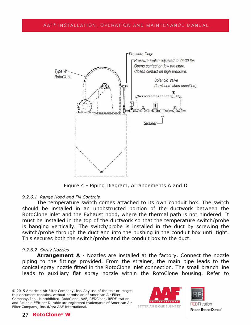
A by-pass connection with manual valve per Figure 4 (both Arrangement A and D) may be included to safeguard operation of
RotoClone in case of solenoid valve failure or for strainer maintenance.
27 RotoClone® W
© 2015 American Air Filter Company, Inc. Any use of the text or images this document contains, without permission of American Air Filter Company, Inc., is prohibited. RotoClone, AAF, REDClean, REDFiltration, and Reliable Efficient Durable are registered trademarks of American Air Filter Company, Inc. d/b/a AAF International.
Figure 4 - Piping Diagram, Arrangements A and D
9.2.6.1 Range Hood and FM Controls
The temperature switch comes attached to its own conduit box. The switch
should be installed in an unobstructed portion of the ductwork between the RotoClone inlet and the Exhaust hood, where the thermal path is not hindered. It
must be installed in the top of the ductwork so that the temperature switch/probe is hanging vertically. The switch/probe is installed in the duct by screwing the
switch/probe through the duct and into the bushing in the conduit box until tight. This secures both the switch/probe and the conduit box to the duct.
9.2.6.2 Spray Nozzles
Arrangement A - Nozzles are installed at the factory. Connect the nozzle piping to the fittings provided. From the strainer, the main pipe leads to the
conical spray nozzle fitted in the RotoClone inlet connection. The small branch line leads to auxiliary flat spray nozzle within the RotoClone housing. Refer to

28 RotoClone® W
© 2015 American Air Filter Company, Inc. Any use of the text or images this document contains, without permission of American Air Filter Company, Inc., is prohibited. RotoClone, AAF, REDClean, REDFiltration, and Reliable Efficient Durable are registered trademarks of American Air Filter Company, Inc. d/b/a AAF International.
installation diagram, Figure 2. Flat spray should be in the 7 o’clock position with
“fan” parallel to the blades of the impeller.
Arrangement D - Nozzles are installed at the factory. Connect nozzle piping to the fittings provided. Refer to erection diagram, Figure 3. From the strainer, the
main line branches into two connections, one leading to two or more vertical flat spray nozzles fitted at the pre-cleaner inlet and the other one to a conical spray
nozzle fitted into the RotoClone inlet connection. From this line, a small branch leads to an auxiliary flat spray nozzle within the RotoClone® housing.
9.2.6.3 Sludge connection
Arrangement A - The expansion chamber and outlet connection drains
should discharge to an open funnel, so if drain piping plugs up, water will run over
funnel and not back up in RotoClone which may cause damage. See Figure 2. Piping from funnel should be equal or larger in size than expansion chamber
nipple. This connection can run to (1) sewer or drain line, (2) process, (3) settling tank, or (4) other locations dependent on local conditions/regulations and the
amount of material collected by the RotoClone.
Arrangement D - The hopper drain should discharge into an open funnel. See Figure 3. Piping from the funnel should be equal or larger in size than the
hopper drain opening. The sludge can be disposed the same as suggested under Arrangement A.
9.2.6.4 Drain Connection
Arrangement A - The drain from the outlet connection, see Figure 2, should be connected to the sludge pipe from expansion chamber or directly to a
drain. Full size piping should be used. Refer to installation diagram Figure 1. Note that a funnel is shown under the drain. This provides easy access to the drain if an
obstruction should occur. A plugged drain can cause the water level in the collector to rise into the impeller and the impeller tips will break.
Arrangement D - The drain from the outlet connection should be piped
back into the RotoClone hopper (see Figure 3).
9.2.6.5 Emergency Overflow (arrangement D only)
Connect pipe nipple located on hopper side to open drain funnel using same
size pipe. See Figure 3. Connection from funnel to sludge line must be no smaller than main drain connection at bottom of RotoClone hopper.

29 RotoClone® W
© 2015 American Air Filter Company, Inc. Any use of the text or images this document contains, without permission of American Air Filter Company, Inc., is prohibited. RotoClone, AAF, REDClean, REDFiltration, and Reliable Efficient Durable are registered trademarks of American Air Filter Company, Inc. d/b/a AAF International.
9.2.6.6 Food Quality RotoClone W
Installation and Operation procedure is the same as shown in Sections 9.2
and 10 of this IOM, with the exception of the requirement for extra water connections. Additional, valved, 40 psi, water supply connections should be made
for the spray nozzle connections (screwed coupling(s) - see general Arrangement drawing for location(s)) in the Expansion Chamber and 90° Elbow or Centrifugal
Outlet (if other than the Straight Outlet is supplied). It is recommended that the valves be opened intermittently, for a brief period, during RotoClone operation and
at shutdown, to facilitate flushing of material that can accumulate and plug the
drains. Frequency and duration of the water spray must be determined individually for each RotoClone application. (Provision can be made for automatic operation, by
installing solenoid valves, actuated by timers.)
NOTE: Leaving the water “on” during operation of the RotoClone can result in water carryover in the exhaust duct; and, will result in excessive water
consumption. An empirically determined timed sequence should be adequate to keep drains free-flowing, and is the recommended operational approach.
9.2.6.7 Flow Switches for Range Hood and FM Controls
Flow switches are shipped assembled on the external piping assembly, which is shipped loose. They are referred to as FS-1 and FS-2. Flow switch FS-1 is
connected to the standard inlet nozzle and the impeller flushing (auxiliary) nozzle. Flow switch FS-2 is connected to the emergency spray nozzle(s). Flow switches are
set at the factory and should not be field adjusted. Each flow switch is set for a specific flow and is not interchangeable. The flow switches need only be wired up
according to the separate wiring diagram.
9.2.6.8 Solenoid Valves for Range Hood and FM Controls
The solenoid valves (SV-1 and SV-2) are shipped assembled on the external
piping assembly, which is shipped loose. The solenoid valves are identical and interchangeable; and need only be wired up according to the separate wiring
diagram.
9.2.6.9 Water connection for Range Hood and FM Controls
The “shipped loose” piping assembly is attached to the RotoClone at the two
unions on the end of the loose piping and connecting pieces on the RotoClone. Connect the water supply line to the strainer on the other end of the RotoClone
piping assembly. It is recommended that a manual shut off valve (supplied by others) be installed in the supply line to facilitate maintenance on the flow

30 RotoClone® W
© 2015 American Air Filter Company, Inc. Any use of the text or images this document contains, without permission of American Air Filter Company, Inc., is prohibited. RotoClone, AAF, REDClean, REDFiltration, and Reliable Efficient Durable are registered trademarks of American Air Filter Company, Inc. d/b/a AAF International.
switches and solenoid valves. The water connection should be capable of supplying
the volume listed in Table 2 at a pressure of 40 psi.
9.2.6.10 Auxiliary Impeller Flushing
The manual or solenoid valve should be piped up to the water line that supplies the RotoClone, after the strainer. The connection size is a ½" FPT on the
valve.
9.2.6.11 Water Usage Table
Table 2. Normal Water Supply Rates
RotoClone Size
Arrangement A Arrangement D
GPM Supplied GPM Supplied
40 50 60 40 50 60
8 1.1 1.2 1.3 2.1 2.2 2.5
10 1.5 1.6 1.8 3.1 3.4 3.8
12 1.8 2 2.2 4.8 5.4 5.9
14 2.3 2.5 2.9 5.3 5.9 6.5
16 3.5 3.9 4.3 7.5 8.4 9.2
20 4.5 5 5.5 8.5 9.5 10.4
24 5.5-6.0 6.2-6.7 6.8-7.3 13.5-14.0 15.1-15.6 16.6-17.1
27 7.0-7.5 7.9-8.4 8.7-9.2
30 8 8.9 9.8
33 12 13.4 14.7
36 14.0-15.0 14.7-15.7 16.7-17.1
45 21.0-22.0 23.6-24.6 25.9-26.9
Notes: 1. Decreased or increased water requirements can be provided by changing
nozzle size.
2. For air temperatures in excess of 300F, cooling spray nozzles should be
provided in inlet duct to compensate for evaporation. A safe
approximation will be 0.2 GPM if additional water per 1000 CFM for each
100°F temperature reduction.

31 RotoClone® W
© 2015 American Air Filter Company, Inc. Any use of the text or images this document contains, without permission of American Air Filter Company, Inc., is prohibited. RotoClone, AAF, REDClean, REDFiltration, and Reliable Efficient Durable are registered trademarks of American Air Filter Company, Inc. d/b/a AAF International.
Table 3. Spray Nozzles
RotoClone Size
Inlet Nozzle (GPM)1
Impeller
Auxiliary Nozzle
(GPM)2
Arr. D Pre-
cleaner Nozzles
(GPM)2
Total Water
Requirements @ 40 psi
Arr. A Arr. D
8 0.6 0.5 0.5 1.1 2.1
10 1.0 0.5 0.8 1.5 3.1
12 1.0 0.8 1.5 1.8 4.8
14 1.5 0.8 1.5 2.3 5.3
16 2.0 1.5 2.0 3.5 7.5
20 3.0 1.5 2.0 4.5 8.5
24 3.5-4.0 2.0 4.0 5.5-6.0 13.5-14.0
27 5.0-5.5 2.0 7.0-7.5
30 6.0 2.0 8.0
33 8.0 4.0 12.0
36 10.0-11.0 4.0 14.0-15.0
45 15.0-17.0 6.0 21.0-22.0
Notes: 1 Hollow Cone Nozzle with 70 to 90 degree spray pattern
2 80 to 90 degree flat spray pattern
Table 4. Water Requirements for Range Hood and FM Controls
RotoClone Size
8 10 12 14 16 20 24 27 30 33 36 45
Normal (GPM)
1.1 1.5 1.8 2.3 3.5 4.5 6.0 7.5 8.0 12.0 14.0 22.0
Emergency
(GPM) 1.3 4.0 4.0 3.2 4.0 6.0 6.0 12.0 12.0 14.0 14.0 30.0
Combined
(GPM) 2.4 5.5 5.8 5.5 7.5 10.5 12.0 19.5 20.0 26.0 28.0 52.0

32 RotoClone® W
© 2015 American Air Filter Company, Inc. Any use of the text or images this document contains, without permission of American Air Filter Company, Inc., is prohibited. RotoClone, AAF, REDClean, REDFiltration, and Reliable Efficient Durable are registered trademarks of American Air Filter Company, Inc. d/b/a AAF International.
9.2.7 Ductwork Installation
Arrangement A - Inlet and discharge ducts must be supported from floor, wall, or ceiling, and not by the RotoClone. The joint between the RotoClone inlet
and exhaust main must be water-tight. Inlet duct should slope downward with bottom of duct no lower than bottom of RotoClone inlet. There should be at least
four (4) duct diameters of straight run leading to the inlet of the RotoClone or performance may be impaired. Discharge duct should extend above roof line and
should discharge the air vertically upward. It should be of same diameter as the RotoClone inlet and seams must be soldered or welded water-tight. A gasket (not
furnished) should be placed between the outlet connection and the discharge duct to make joint water-tight. A weather hood is not required. Expansion chamber
should be vented per Figure 5, where recirculation of discharge air is not permitted.
Figure 5- Expansion Chamber Venting Diagram
Arrangement D - Instructions same as Arrangement A except on arrangement D, the joint between Pre-cleaner inlet and exhaust main must be
water-tight.

33 RotoClone® W
© 2015 American Air Filter Company, Inc. Any use of the text or images this document contains, without permission of American Air Filter Company, Inc., is prohibited. RotoClone, AAF, REDClean, REDFiltration, and Reliable Efficient Durable are registered trademarks of American Air Filter Company, Inc. d/b/a AAF International.
10 START-UP & OPERATION To make sure the impeller is free, turn shaft by hand before starting the
RotoClone. THE DIRECTION OF ROTATION MUST BE COUNTERCLOCKWISE when
viewed from the drive side of RotoClone, NOTE ARROW ON HOUSING.
Flush strainer to remove pipe scale and solids from supply line. Paper, wood, and other foreign materials are frequently left in exhaust system during erection.
Inspect RotoClone impeller through inspection doors located at RotoClone inlet and
rear housing before operating the unit and after 24 hours operation. Remove any such accumulations conveyed to the RotoClone impeller, and check all drains for
blockage.
10.1 Start-up checklist TO START RotoClone:
1. Open valve in water supply line (unless automatically controlled).
2. Start RotoClone motor.
TO STOP RotoClone:
1. Stop RotoClone motor.
2. Close valve in water supply line (unless automatically controlled).
CAUTION: Pressure in water supply line to spray nozzles must be maintained at 40 lb. per square inch (psi) or higher during RotoClone
operation.
Do not permit paper, waste, or similar large pieces of material to be thrown into suction hoods because they will plug the RotoClone and cause water and dust
to escape through the clean air discharge or will plug drains, allowing water to build up and damage the impeller.

34 RotoClone® W
© 2015 American Air Filter Company, Inc. Any use of the text or images this document contains, without permission of American Air Filter Company, Inc., is prohibited. RotoClone, AAF, REDClean, REDFiltration, and Reliable Efficient Durable are registered trademarks of American Air Filter Company, Inc. d/b/a AAF International.
11 MAINTENANCE 11.1 Record Keeping
It is suggested that a record is kept of operational data and that all servicing
maintenance is recorded.
Maintenance data to be recorded should include details of inspections and any parts replaced.
11.2 Lubrication
Flush and refill pillow block bearings on RotoClone shaft per attached schedule. Using amounts listed below. #2 S.R.I. type grease is recommended.
For 2 piece split bearings, 12 hours/day, 5 days/week operation, the
bearings should be lubricated every 6 months, as follows (Note: this type of bearing should not be over greased).
Table 5. Bearing Lubrication
RotoClone Size 8 10 12 14 16 20 24 27 30 33 36
Oz. of grease per Bearing 2 2 3 4 10 10 16 22 28 32 36
For single piece bearings, the following minimum schedule should be
followed for 12 hours/day, 5 days/week operations. This type of bearing can be greased until old grease is forced out of seals.
Table 6. Shaft Seal Lubrication Interval

35 RotoClone® W
© 2015 American Air Filter Company, Inc. Any use of the text or images this document contains, without permission of American Air Filter Company, Inc., is prohibited. RotoClone, AAF, REDClean, REDFiltration, and Reliable Efficient Durable are registered trademarks of American Air Filter Company, Inc. d/b/a AAF International.
Lubrication Interval
RotoClone
Size
Cu. In.
Grease
6mos 4mos 2mos
Max Operating Speed
(RPM)
8 0.3 2400 3600 5000
10 0.3 2400 3600
12 0.4 2000 3000
14 0.8 1700 2500
16 0.8 1450 2200
20 0.8 1450 2200
24 1.2 1300 1900
27 1.7 1200 1800
30 2.3 1100
33 3.1 1000
36 3.1 1000
45 4.3 900
Grease shaft seal at same time as bearings. Water leakage is an indication of insufficient grease. 11.3 Nozzles and Strainer
Flush out strainer periodically and inspect spray nozzles for proper water
delivery and pattern. Since water quality varies, a monthly inspection, for the first
year of operation is recommended, in order to determine a maintenance schedule.
On a Food Quality RotoClone W, special attention should be paid to the spray nozzles and areas where there are quick opening access doors. These areas often
require more frequent cleaning. It is recommended that a preventative maintenance schedule be developed specific to each W RotoClone.
11.4 RotoClone Inlet (Arr. A)
Open inspection door at RotoClone inlet connection and remove any accumulation in the inlet at the border line of the wet and dry section. The
frequency of cleaning varies for each installation and must be determined by frequent inspection when RotoClone is first placed in service. Clean out before
accumulation obstructs one-tenth of cross section area or inlet connection. Clean sludge from RotoClone inlet door before closing.

36 RotoClone® W
© 2015 American Air Filter Company, Inc. Any use of the text or images this document contains, without permission of American Air Filter Company, Inc., is prohibited. RotoClone, AAF, REDClean, REDFiltration, and Reliable Efficient Durable are registered trademarks of American Air Filter Company, Inc. d/b/a AAF International.
11.5 Pre-cleaner Inlet (Arr. D) Under certain operating conditions, a deposit of dust will occur at the border
line of the dry and wet zones in the pre-cleaner inlet. The removal of this deposit must become a part of regular maintenance. The frequency of removal can be
established only by periodic inspections when the RotoClone is first put in operation. The deposit should never be allowed to obstruct more than one quarter
of the area of the pre-cleaner inlet.
A door is provided at the pre-cleaner inlet to remove this accumulation. Be sure spray nozzle is not damaged or clogged and that nozzle orifice is vertical.
Gasket seal should be cleaned before closing inlet door. 11.6 RotoClone Impeller
Inspect the RotoClone impeller periodically for accumulations of foreign
material or obstructions in blade hooks. The blade hooks formed by the leading edge of the impeller blades convey the collected dust and water out of the
airstream. A buildup of dust within these hooks may be sufficient to cause pronounced vibration or dust and water entrainment. Such accumulations should
be removed either by flushing with high velocity water jet or scraping with long screw driver through access door in back of RotoClone housing and from front side
of impeller.
Flat spray of flushing nozzle located at impeller (7 o’clock position, viewed
from the inlet) should be parallel to blade edges. Check this spray with water on periodically to ensure proper positioning and spray pattern.
Certain accumulations in RotoClone impeller cause no difficulty and can be
disregarded. They include minor deposits on back of impeller blades, slight coating or small deposits on front side of blades, and slight deposits in blade hooks that do
not obstruct flow of dust and water.
11.7 Drains
Keep all drains clean. If necessary flush out periodically. A plugged drain can
cause damage to the impeller. Inspect grating in bottom of the Arr. D RotoClone hopper periodically and remove any accumulation.

37 RotoClone® W
© 2015 American Air Filter Company, Inc. Any use of the text or images this document contains, without permission of American Air Filter Company, Inc., is prohibited. RotoClone, AAF, REDClean, REDFiltration, and Reliable Efficient Durable are registered trademarks of American Air Filter Company, Inc. d/b/a AAF International.
11.8 Emergency Overflow (Arr. D only)
An emergency overflow is provided on side of hopper to drain off the water in case hopper drain pipe becomes clogged. This stoppage must be cleared
immediately.
11.9 Shaft Seal Other than routine greasing of the shaft seal (see 11.2 Lubrication), the
shaft seal requires no maintenance. Should the seal fail, replacement of the two seals as shown in Figure 6 may be necessary. Since the seals are “split”, it is
usually not necessary to remove anything, other than the seals, from the shaft itself, unless damage to the seal housing or metal spacer (located between the
two seals) is evident. On the smaller RotoClone, it may be necessary to loosen the bearing closest to the seal and move it back about 6 inches, to gain clearance to
remove the seal housing. Be certain that the position of the shaft in relation to the RotoClone is not changed in any direction when doing this.
1. Remove the seal housing by removing the nuts securing it to the scroll, and slide the housing back, exposing the seals and spacer. Discard old
seals.
2. Inspect the shaft and seal housing to ensure that they are clean and smooth. Remove any rust buildup with emery cloth or steel wool. Inspect
metal spacer; replace if necessary (this will require removing bearings to slip spacer off the shaft and install new spacer. Be sure to reposition impeller per
Figure 7, before tightening bearings back in place).
3. Place a small amount of silicone sealant between the radial cut on each seal.
4. Install the new seals on either side of the spacer with the radial cut at
the top and the garter springs circling the inner lip of each seal.
5. Ensure that the radial cut in the metal spacer is located directly below
the grease fitting in the seal housing to allow grease flow.
6. Install the seal housing and tighten the nuts.
7. Lubricate the seal thoroughly with No. 2 grease.

38 RotoClone® W
© 2015 American Air Filter Company, Inc. Any use of the text or images this document contains, without permission of American Air Filter Company, Inc., is prohibited. RotoClone, AAF, REDClean, REDFiltration, and Reliable Efficient Durable are registered trademarks of American Air Filter Company, Inc. d/b/a AAF International.
8. Replace any bearings, if removed, in original position and check
impeller clearance per Figure 7 before tightening bearings onto shaft.
Figure 6. Construction details of the RotoClone W shaft Assembly
11.10 Replacement of Shaft, Impeller or Water Cone Removal of the shaft, impeller, or water cone requires access to the front of
the scroll. This is most easily accomplished by removing the inlet piece and scroll inlet cone. The water piping should be disconnected before removing the inlet
sections. The water cone should be marked to indicate the bolt hole locations in relation to the scroll, before removal. The old water cone can be used to match
mark the replacement water cone, which comes undrilled. Note the distance from the back of the impeller to the scroll before removing the impeller. The impeller is
fastened to the shaft by a taper lock hub.
It is easiest to remove the impeller from the shaft by using a wheel puller,
after unbolting the hub; or one can reinsert the hub screws into the unused holes in the hub to “push” the shaft off of the hub. However, on units that have been in
service for years, this method may not provide the necessary force to “break” the hub away from the shaft, and the wheel puller will be necessary. Finally, the
bearings and driven sheave are taken off and the shaft can be removed.
Reinstallation is the reverse of removal. The shaft is replaced and the bearings and driven sheave tightened back onto it. New set screws should be
used, when single piece bearings are supplied, as the old ones will most likely have blunted ends that can no longer adequately secure the collar to the shaft. Be

39 RotoClone® W
© 2015 American Air Filter Company, Inc. Any use of the text or images this document contains, without permission of American Air Filter Company, Inc., is prohibited. RotoClone, AAF, REDClean, REDFiltration, and Reliable Efficient Durable are registered trademarks of American Air Filter Company, Inc. d/b/a AAF International.
sure to tighten the set screws to the proper torque as recommended by the
bearing supplier (or contact AAF for recommendation). The impeller is reattached to the shaft, but the taper lock hub screws are not tightened yet. All old gasket
material should be removed from the scroll and water cone. A new water cone gasket should be cemented to the water cone. The water cone is then reattached
to the scroll using the match marks to orient it in the same position as the original. The impeller is then checked for proper distance from the water cone edge using
Figure 7 and the Table 7.
The taper lock hub screws are tightened after confirming the proper position of the impeller. Note that the impeller may shift as the hub is tightened onto the
shaft; the impeller position should be checked while tightening the hub and repositioned as necessary. A wooden block and hammer can be used to “tap” the
impeller back if required. Recheck the impeller position and rotate the impeller to insure that it turns freely, once the impeller is locked onto the shaft. The inlet
pieces and piping can then be reattached. A waterproof caulking/gasket is used
between the inlet flanges; remove any old material before reinstalling, and be sure to encircle bolt holes with caulk, or leaks may result.
Figure 7. Field Replacement of RotoClone W Impeller

40 RotoClone® W
© 2015 American Air Filter Company, Inc. Any use of the text or images this document contains, without permission of American Air Filter Company, Inc., is prohibited. RotoClone, AAF, REDClean, REDFiltration, and Reliable Efficient Durable are registered trademarks of American Air Filter Company, Inc. d/b/a AAF International.
Table 7: Distance of Impeller from Water Cone
RotoClone
Size C = Cap Screws
F= Impeller
Clearance
8 3/8 - 16 x 1 5/16 - 7/16
10 3/8 - 16 x 1 7/16 - 9/16
12 3/4 - 10 x 1 9/16 - 11/16
14 3/4 - 10 x 1 9/16 - 11/17
16 3/4 - 10 x 1 5/8 - 7/8
20 3/4 - 10 x 1 13/16 - 1 1/16
24 3/4 - 10 x 1 1 1/8 - 1 3/8
27 3/4 - 10 x 1 1 1/8 - 1 3/8
30 5/8 - 10 x 1 1 5/16 - 1 11/16
33 3/4 - 10 x 1 1 5/16 - 1 11/16
36 3/4 - 10 x 1 1 5/8 - 1 15/16
45 3/4 - 10 x 2 3/4 2 - 2 1/2

41 RotoClone® W
© 2015 American Air Filter Company, Inc. Any use of the text or images this document contains, without permission of American Air Filter Company, Inc., is prohibited. RotoClone, AAF, REDClean, REDFiltration, and Reliable Efficient Durable are registered trademarks of American Air Filter Company, Inc. d/b/a AAF International.
12 TROUBLESHOOTING 12.1 Water Entrainment
Issue: Excessive discharge of water in the exhaust may be due to the following:
Fix:
Incorrect rotation (correct rotation is counter-clockwise, when
viewed form the drive end).
Incorrect size cone spray or auxiliary nozzles and incorrect spray pattern (i.e. flat spray at 7 o’clock position viewed from the inlet and
parallel to blades and cone spray to be centered at wheel).
Inlet spray should just miss inlet perimeter as it passes into the scroll.
Disturbances at inlet, such as elbows or branch entries, causing
unbalanced airflow or dust loading (see Section 2.3).
Bent blade tips and/or obstructions in impeller such as rags, collected material buildup, etc.
• Pluggage of drains.
Incorrect outlet piece location. The bottom of the outlet piece should never be above the bottom of the RotoClone® scroll. Any gasketing
that has squeezed out should be removed.
Improper gasketing of water cone, or damage/wear of the water cone.
• Incorrect water pressure.

42 RotoClone® W
© 2015 American Air Filter Company, Inc. Any use of the text or images this document contains, without permission of American Air Filter Company, Inc., is prohibited. RotoClone, AAF, REDClean, REDFiltration, and Reliable Efficient Durable are registered trademarks of American Air Filter Company, Inc. d/b/a AAF International.
12.2 Dust Entrainment
Issue: Excessive entrainment of dust with the cleaned air may be due to the following:
Fix:
• Equipment running dry or with insufficient water – because of clogged spray nozzles or strainer, or low water pressure, (40 lb.
minimum pressure required at nozzles).
• Obstructions in impeller blade hooks.
• On Arrangement D, spray nozzle in pre-cleaner turned. Flat spray must discharge in a vertical plane.
• Dust loading too heavy.
• Particulate size too small to be captured.
• Disturbances at inlet, such as elbows or branch entries, causing unbalanced airflow or dust loading (see Section 9.2.7).
12.3 Start/Stop Issues
Issue: Water pressure or flow insufficient to actuate flow switch/switches. Fix:
• Supply water pressure less than 40 psi
• Nozzles plugged
• Strainer plugged
• Water usage elsewhere causes momentary interruption in flow to
RotoClone
• Solenoid valve malfunctioning
Issue: Flow switch wired incorrectly
Fix:
• See Note under 9.2.6.7

43 RotoClone® W
© 2015 American Air Filter Company, Inc. Any use of the text or images this document contains, without permission of American Air Filter Company, Inc., is prohibited. RotoClone, AAF, REDClean, REDFiltration, and Reliable Efficient Durable are registered trademarks of American Air Filter Company, Inc. d/b/a AAF International.
Issue: Motor amperage exceeds nameplate full load amps
Fix: • Impeller turning backward
• Airflow or static pressure change in ductwork
• Drains plugged
• Motor and RotoClone sheaves reversed
13 RECOMMENDED SPARE PARTS When ordering Replacement Parts, customer must state Serial Number and
Size of RotoClone, Part Name (when shown on drawing) and Item Number.

44 RotoClone® W
© 2015 American Air Filter Company, Inc. Any use of the text or images this document contains, without permission of American Air Filter Company, Inc., is prohibited. RotoClone, AAF, REDClean, REDFiltration, and Reliable Efficient Durable are registered trademarks of American Air Filter Company, Inc. d/b/a AAF International.

45 RotoClone® W
© 2015 American Air Filter Company, Inc. Any use of the text or images this document contains, without permission of American Air Filter Company, Inc., is prohibited. RotoClone, AAF, REDClean, REDFiltration, and Reliable Efficient Durable are registered trademarks of American Air Filter Company, Inc. d/b/a AAF International.
RotoClone W Parts List:
1. Expansion Chamber Assembly
2. Impeller Shaft
3. Bearing, Shown on 4. Water Cone Assembly
5. Inlet Cone Assembly 6. Impeller Assembly
7. Inlet Connection 8. Cone Spray Nozzle
9. Piping Assembly 10. Monarch Figure 624 Nozzle
11. Housing Assembly
12. Outlet Connection
13. Impeller Hub 14. Hex. Head Cap Screws
15. Impeller Hub Cap 16. Taper Lock Bushing
17. Key 18. Seal Housing Assembly
19. Shaft Seal 2 20. Spacer
1. Standard RotoClone, sizes 16 and smaller, may have inlet, outlet, and
expansion chamber welded to housing in lieu of flanged and bolted connection.
2. Seal consists of two Buna-N pieces and two garter springs. Radial cuts
should be sealed with silicon caulk when installing new seal.

Sales Offices:
Reliable, Efficient, Durable
The information in this document is the property of American Air Filter Company, Inc. (AAFCI) and may not be
copied or distributed to any third party, or used for any purpose other than that for which it is supplied, without
the express written consent of AAFCI.
While the information herein is provided in good faith based on information available when the document was
created, it should not be relied upon as being complete or accurate, and the products advertised within this
document, and their components and accessories, are subject to change without notice. AAFCI provides this
information on an AS IS basis and makes no warranties, expressed or implied, or representations regarding
same. This document does not establish, and should not be taken as establishing, any contractual or other
commitment binding upon AAFCI or any of its subsidiaries or associated companies.
ISO Certified Firm ©2015 AAF InternationalAPC-
Europe, Middle East & Africa
AAF Ltd Bassington Lane, CramlingtonNorthumberland, NE23 8AF UKTel: +44 1670 713 477Email: [email protected]
AAF, S.A. C/ Urartea, 11Polígono Ali-Gobeo01010 Vitoria, SpainTel: +34 945 214851Email: [email protected]
AAF FranceRue Wiiliam DianB.P.327620 Gasny, FranceTel: +33 2 32 53 60 60Email: [email protected]
AAF SriVia Lario, 122070 – Fenegrò (CO), ItalyTel: +39 031 35 25 311Email: [email protected]
AAF Luftreinigungssysteme Gesmbi-iCampus 21Europaring F12 4012345 Brunn am Gebirge, AustriaTel: +43 (0) 2236 677 628 0Email: [email protected]
AAF – Lufttechnik GmbHCentroalle 263 bD 46047Oberhausen, GermanyTel: +49 208 828423 0Email: [email protected]
AAF – Environmental Control Epe1, Ifaistou & Kikladon15354- Glika Nera, GreeceTel: +30 2106632015Email: [email protected]
AAF Hava Filtreleri ve Ticaret ASHürriyet MahallesiYakac1k D-100 Kuzey Yan Yol No: 49/1-234876 Kartal, Istanbul, TurkeyTel: +90 216 4495164/65Email: [email protected]
AAF International – Middle EastFZS1BC01-BC04, Jebel Ali Dubai, UAETel: 009714 8894886Email: [email protected]
AAF Saudi Arabia Ltd.P.O. Box 59336 Riyadh 11525,Kingdom of Saudi ArabiaTel: +966 1 265 0883Email: [email protected]
Asia
America Air Filter Manufacturing Sdn Bhd(Asia Regional Office)Lot 6, Jalan Pengapit 15/19Seksyen 15 40000 Shah AlamSelangor Darul Ehsan, MalaysiaTel: (60) 3 5039 7777 +603 5039 7732Email: [email protected]
AAF (Wuhan) Co. Ltd., (China HQ)268 CheCheng RoadWuhan Economic & TechnologicalDevelopment ZoneWuhan, Hubei Province PR,China 430056Tel: +86 27 8447 3671 +86 27 8447 3672Email: [email protected]
AAF International (Thailand) Co., Ltd.100 Moo 4 Soi Namdang – Bangplee 44Bangkaew Bangplee, Samutprakarn 10540, ThailandTel: +66 2738 7788Email: [email protected]
Daikin Australia Pty Ltd(AAF Australia & New Zealand Sales Office)15 Nyadale Road Scoresby Victoria 3179,AustraliaTel: +61 (0)3 9237 5562Email: [email protected]
North & South America
AAF International9920 Corporate Campus Drive, Suite 2200Louisville, KY 40223-5000, USATel: 1 502 637 0011Toll Free: 1 800 477 1214Email: [email protected]
AAF, S de RL de CVAv. Primero de Mayo No. 85,Col. San Andrés Atenco,C.P. 54040 Tialnepantla Edo. De Mexico, MéxicoTel: +52 55 5565 5200Email: [email protected]
American Air Filter Brasil Ltda.Rua Doutor Bacelar, 173-CJ. 121 Vila Clementino – São Paulo – BrazilCEP 04026-000Tel: +55 11 5567 3000Email: [email protected]