aai - banggoodimg.banggood.com/file/products/20160922213704n1201sa - user … · aai...
TRANSCRIPT
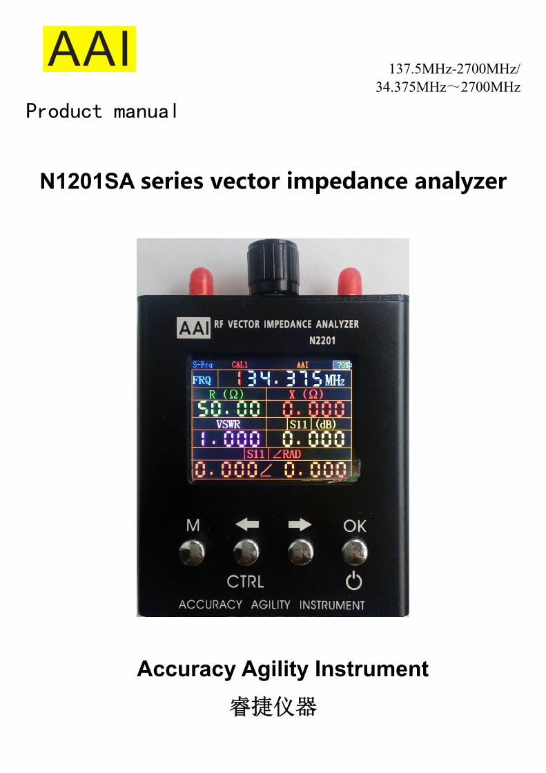
AAI 137.5MHz-2700MHz/
34.375MHz~2700MHz
Product manual
N1201SA series vector impedance analyzer
Accuracy Agility Instrument
睿捷仪器
Brief introduction
N1201SA series is the handheld radio frequency vector impedance measurement
analysis instrument,Easy to use, simple operation. Built-in high capacity lithium ion battery for mobile and outdoor use. Shutdown automatically save Settings parameters, without human intervention, after starting up, interface Settings completely the same as the power off before, use very worry.
Can be used to test the antenna, the impedance of the radio frequency devices .
As RF impedance measuring need calibration, so you need to purchase separately calibration。
N1201SA series is divided into three sub models:N1201SA,N1201SAC,N1201SA+,
The N1201SA is basic, N1201SA + is enhanced,Frequency range is expanding, the
other is exactly the same。N1201SAC is a custom model, on the basis of N1201SA increased the serial data output, cable length and characteristic impedance of a transmission line measurement function.
The main technical indicators
N1201SA technical indicators
model N1201SA N1201SAC N1201SA+ Working frequency 137.5MHz~2700MHz 137.5MHz~2700MHz 34.375MHz~2700MHz
The frequency step by step 1kHz
display 2.4 inch TFT resolution 320×240(QVGA)
Battery capacity 2000mAH(7.4Wh)
Power consumption <1.5W
Charging current 400mA
Charger port
USB(only act as
charge port)
Output measurement data in
serial port
USB(only act as charge
port)
Automatic shun-down Can be set(it has been open for 5minutes~60minutes optional)
Measurement parameters resistance,reactance,standing,s11
resolution Four significant figures
Frequency accuracy <±3ppm
connector SMA-K
impedance 0.1Ω~1000Ω(The absolute value of the impedance)
standing 1.000~65 Measurement
range s11(dB) 0dB~-60dB
impedance < The absolute value of the impedance×5%±0.1Ω(Z小于 200Ω,<1.5GHz)
standing < Effective reading×10%±0.1
s11 0.1 dB /5° (0dB~-10dB)
(dB/°) 1 dB /10° (-10dB~-20dB)
Error
(single-point
measurement) 5dB/20° (-20dB~-40dB)
Directivity <35dB(140MHz~2GHz Calibrated),<30dB(2GHz~2.7GHz)
Scan Points 280
Output Level -18dBm
Work temperature 0℃~40℃
Atmospheric pressure 860hPa~1060hPa
Cable length measurement —— <3m ——
Transmission line
characteristic impedance
measurements —— 10Ω~300Ω ——
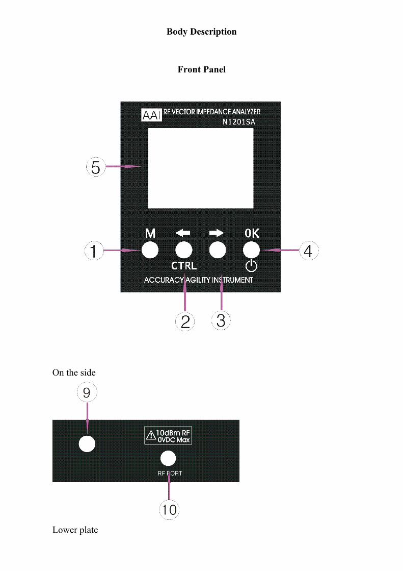
Body Description
Front Panel
On the side
Lower plate

Buttons and interface function No. Mark Name Function description
1 M Main menu (menu)
button
Touch the main course, a single press this
key role is to measure the interface
switches to "Spot" or "Scan Mode." Hold down
the CTRL key and then press the M key
instrument among the "System Information"
and "calibrate" switch
2 ← Left direction and
CTRL key
And to the left of the object you want to
modify, the second function, CTRL, used in
conjunction with M
3 → Right arrow keys Right arrow keys, move the object to modify
4 OK Determine and Off
button
Sure you want to edit. The second function
switch (long press shutdown)
5 LCD LCD
6 RESET Instrument reset
hole
If deadlocks or other problems arise
instrument, try resetting the instrument。
7 CHARGE charging port
Using Mini USB interface, but only as a
charging port use, data transfer
temporarily open. Please use high-current
mobile phone charger (requires a supply
current> 1A), please do not take the
computer USB port charging, because the
instrument itself is a great power, the
computer USB port is insufficient current
may cause the computer not working
properly.
8 charging indicator Instrument standby, charging indicator
light
9 Adjustment knob Adjust parameter number,move modified
objects
RF PORT RF port(SMA-K) DUT or RF cable connected to this port
.
Function Description
There are four operation interfaces, single point measurement, Scan function, system information and calibration. The default power-on interface is single point measurement
Power-on and power-off
When the analyzer is power-off, keep pressing the Ctrl key and press the Power key once, and the analyzer is turned on. When the analyzer is power-on, press the power key for two seconds, then release, and the analyzer is turned off.
Crash and reset
In case of intense interference or unusual operation, dead lock may occur. Dead lock may run out of the battery power, which can cause damages to the battery. To avoid that, reset the analyzer when deadlock occurs. When the battery power is drained off, choose chargers featuring enough current to charge the analyzer.

Single point measurement
Single-point measurement using a very simple, only one parameter needs to be adjusted, that is a single point measurement frequency. Be adjusted to the number of bits of red, left-right can be selected to adjust the position, rotating the adjustment knob to change the value of this bit, after adjusting the frequency, the measurement results are automatically updated. Note that this digital instrument elsewhere adjustment methods are similar to the above process.
The case of single point measurement press the OK button, you can switch impedance and S-parameter measurements and capacitance and inductance measurements.
Measuring about some of the experiences described
S11 Magical. S11 and VSWR can be used to characterize the antenna or RF circuit matching degree. But the S11 have some of the features of its own. Such as measuring the loss of the cable, is generally used S21, namely vector network analyzer or scanner to measure the two ports, in fact, use a single port impedance analyzer can also be measured. A cable connected to our RF impedance analyzer port, the other end open. Then read S11 divided by 2, that is, this RF cable loss, of course, would be accurate to low frequency, high frequency, then the frequency fluctuates with the change, it is best to use the sweep function, adjacent The maximum and minimum mean it.。

Scan function
Single-point measurement mode,press the M key, it will switch to the scan function
interface
Scan function There are five types of parameters can be modified:
1. Scan Parameter Type
Respectively, S11, VSWR, | Z |, R, X, a total of five kinds of scan parameters 2. Scaling factor 1. Scale display that is the y-axis, according to the DUT value to adjust the ratio of the
display Mark point frequency
2. Scan the drawing frequency point mark 3. Start frequency
Starting frequency sweep,N1201SA lowest frequency of 140MHz
4. End frequency Stop frequency scanning,N1201SA highest frequency of 1100MHz

Parameter adjusting method
5. There are two parameters to adjust status: parameter selection and parameter adjustment mode, press the "OK" button to switch between these two states. parameter selection state, press the left or right button or turn the knob to select the parameters to be adjusted, the parameters are selected into a full red (start frequency, stop frequency, MK point three parameters from the original color changes to red, It indicates that the parameter is selected), or a red box (the type of scan parameters or scaling factor). After pressing the "OK" button to switch to adjust the parameters to the state, then the selected parameter changes to yellow box red box (the type of scan parameters or scaling factor), wherein the numerical parameters (start frequency, stop frequency, MK points) be adjusted position turns red. Similar adjustments with a single point mode parameter, namely left and right keys to select the desired position of the knob to adjust the value of the parameter. Tip: The instrument knob with key function, the same buttons and knobs "OK" button
function, select the parameters, use the dial button will be a lot easier.
The above instructions for use are relatively simple, in fact, the use of very simple, little careful experience to understand.
During use, the different measurements required to adjust the ratio of the display, if the ratio of the display is inappropriate, can not well reflect the results of the measurements.
Scan function with a single point measurement value measured at the point mark is different. Actually measuring the frequency of the current is not accurately mark points of this frequency, but with the closest scanning frequency value。For example, now scanning frequency of 1000MHz to 1280MHz, mark point frequency is set to 1200.45MHz, actual measured with 1200.45MHz latest 1200MHz This frequency value, if the frequency is just sensitive point, it may be more obvious difference that there are two ways, one is single-point measurement value, whichever one is to try to reduce the swath width. There are many users consult our talent if you can see the resonance point of the antenna, in fact, simply open the scanning feature to scan the VSWR function, see where the standing wave minimum, the resonance point where the basic is, of course, was the definition of the resonance point will there are some differences, this time can be anti-resistance curve based on a standard scan curve or electricity.
System information

In single point mode or scan function interface, hold down the CTRL key (second function
button), press the M key, then switch to the system information interface, system information is
mainly information about the instrument, wherein the automatic shutdown parameters can be
modified, Turn the knob or press the left into effect right to edit, modify, after pressing "OK"
button to keep the parameter.
Cable length measurements (N1201SAC models only)
Currently cable length measurement is limited to within 3 meters.
In the scanning interface, click the M key to enter the cable length measurement interface, the measurement is shown below.
Picture omitted
Test step:
1. Press the M key to switch the instrument interface to the "Cable length measurement" interface. The cable under test to the instrument, and the other end open (nothing connected)
2. Enter the dielectric constant of the cable.
3. Read data
Characteristic impedance measurement (only N1201SAC models) "Characteristic impedance measurements" and "Cable length measurement" is used in conjunction. The main features characteristic impedance measurement for pcb trace impedance measurement, specifically recommendation goes a characteristic impedance of the line to do the

test, recommended length of about 6 ~ 7cm more appropriate (shortest not less than 3cm).
Test Procedure:
1. in the "cable length measurement" test the transmission line length. Press ok key to switch to the "characteristic impedance measurement" and the other end of the transmission line access terminal load value and terminal load (for the sake of measurement accuracy to make use of high-precision 50 ohm load) into the instrument.
2. read data.
Serial data output function (only N1201SAC models)
Serial data output is unidirectional output:Sent out from the inside of the instrument through the serial port baud rate 9600bps.
Serial port voltage is 3.3V level, the USB to serial chip output level Please use a 3.3V. Switching serial data output function:For compatibility with manual measurement, only the information in the system will shut down automatically modify the interface has been switched to output output to open.
When single-point test function, about a fraction of a second output, the output data format for example as follows:
single-point,frequency: 150000 ,resistance: 8497,reactance:956325, standing
wave:2158647, Return Loss: -8,|impedance|:956362,parameter|s11|∠RAD: 999 104
All data are magnified by the output integer (no decimal point), itemized below explain
Single point represents a single point measurement means
frequency: 150000 indicates150MHz
Resistance: 8497 represents 8.497 ohm
Reactance: 956 325 represents 956.325 ohms
VSWR: 2,158,647 represents 2158.647
Return loss: -8 expressed -0.008dB
Impedance |: 956362 represents 956.362 ohms
s parameters | s11 | ∠RAD: 999 104 indicates | s11 | = 0.999 rad = 0.104 +
Scan test data format (per scan a frequency output data)
F= 1546875 , R = 1
F= 1546875 represents frequency 1546.875MHz
取消 R = 1 represents the resistance parameter is being scanned, the resistance value of the current point is 0.001 Euro Cable length measurement data format
TLINE= 508 represents the measured cable length 0.508 m。

Serial cable wiring instructions
USB MINI borrow serial interface, the interface line sequence shown in the following table.
Serial cable wiring
instructions
instrument PC
1 +5V input +5V output
2 RX TX
3 TX RX
4 NC NC
5 GND GND
Correction and calibration
△! In explaining the calibration method of operation, the first special note
that if you are not the hands of the calibration member, please do not do calibration, the instrument has been calibrated in production to SMA port, can be used directly。
In what circumstances need to be calibrated:
1、 you need to do precise measurements, calibration using the calibration member
DUT is not directly connected to the port together, but after a period of cable, and you need to measure the DUT parameters such as resistance and reactance
pay attention: Logo "school 0" in red on the instrument, is to use the system calibration parameters, ie calibration port on the instrument's RF port. "School 1" indicates that user calibration data. If you use the adapter, the case at lower frequencies, but also eliminates the need for calibration.

First, a description of calibration and discrimination calibration concepts. Used vector network knows, to accurately measure the RF impedance of the device under test, the test must be calibrated cables. But some correction is less clear.
After the test cable, using the calibration member on the cable to calibrate and maintain the results of the calibration (ie calibration parameters). When using the test cable test DUT, if using the calibration parameters of the measurement result is corrected, the result is corrected, if not using the calibration parameters to correct measurement results, the result is not corrected.
That is to say, the correction of the choice is to measure the measured parts, whether the use of calibration parameters to correct the results of the measurement.
In the system information interface state, hold down the CTRL key, press the M key, then switch to the correction and calibration interface.
The upper half of the left side of the interface is the correct choice, there are two options, namely, "system correction" and "user correction ". When selecting the system correction , the instrument's measurement standard surface at the SMA port of the instrument.
The lower half of the left side of the interface is the calibration choice.
Press the left or right key can switch in the correction and calibration of the two options, turn the knob can choose specific projects. Calibration is selected, press the "OK" button to start the calibration. Note that calibration once after the start is irreversible. That is, it must be coming to the end of a calibration procedure, because once you start after calibration, the previous calibration data have all been cleared.

The instrument calibration using SOL calibration, namely open circuit (OPEN), short circuit (SHORT), load (LOAD) three kinds of calibration.
Calibration procedure:
Select the highlighted selection in the "port calibration", press the "OK" key, that is, the beginning of the calibration process.
Enter the calibration process began to have a preparation process, the preparation process is completed, it will be prompted to access the circuit breaker, press the left button to calibrate
Calibration process takes a little time:"

And then the short circuit.
Then the calibration of the standard load.
After all the calibration is completed
:

Note: for users, each calibration will automatically change the calibration options to user calibration. At the same time, in order to ensure the integrity of the calibration, calibration process, automatic shutdown function failure, that is, to keep the boot.