aalborg universitet a circulating current suppression...
TRANSCRIPT

Aalborg Universitet
A Circulating Current Suppression Method for Parallel Connected Voltage-Source-Inverters (VSI) with Common DC and AC BusesWei, Baoze; Guerrero, Josep M.; Quintero, Juan Carlos Vasquez; Guo, Xiaoqiang
Published in:Proceedings of 8th IEEE Energy Conversion Congress and Exposition (ECCE), 2016
DOI (link to publication from Publisher):10.1109/ECCE.2016.7854655
Publication date:2016
Document VersionEarly version, also known as pre-print
Link to publication from Aalborg University
Citation for published version (APA):Wei, B., Guerrero, J. M., Quintero, J. C. V., & Guo, X. (2016). A Circulating Current Suppression Method forParallel Connected Voltage-Source-Inverters (VSI) with Common DC and AC Buses. In Proceedings of 8th IEEEEnergy Conversion Congress and Exposition (ECCE), 2016 IEEE Press. DOI: 10.1109/ECCE.2016.7854655
General rightsCopyright and moral rights for the publications made accessible in the public portal are retained by the authors and/or other copyright ownersand it is a condition of accessing publications that users recognise and abide by the legal requirements associated with these rights.
? Users may download and print one copy of any publication from the public portal for the purpose of private study or research. ? You may not further distribute the material or use it for any profit-making activity or commercial gain ? You may freely distribute the URL identifying the publication in the public portal ?
Take down policyIf you believe that this document breaches copyright please contact us at [email protected] providing details, and we will remove access tothe work immediately and investigate your claim.
Downloaded from vbn.aau.dk on: juli 14, 2018

A Circulating Current Suppression Method for Parallel Connected Voltage-Source-Inverters (VSI)
with Common DC and AC Buses
Baoze Wei, Josep M. Guerrero, Juan C. Vásquez Department of Energy Technology
Aalborg University Aalborg, Denmark
[email protected], [email protected], [email protected]
Xiaoqiang Guo Department of Electrical Engineering
Yanshan University Qinhuangdao, China
Abstract—This paper describes a theoretical with experiment study on a control strategy for the parallel operation of three-phase voltage source inverters (VSI), to be applied to uninterruptible power systems (UPS). A circulating current suppression strategy for parallel VSIs is proposed in this paper based on circulating current control loops used to modify the reference currents by compensating the error currents among parallel inverters. Both of the cross and zero-sequence circulating currents are considered. The proposed method is coordinated together with droop and virtual impedance control. In this paper, droop control is used to generate the reference voltage of each inverter, and the virtual impedance is used to fix the output impedance of the inverters. In addition, a secondary control is used in order to recover the voltage deviation caused by the virtual impedance. And the auxiliary current control loop is added to acquire a better average current sharing performance among parallel VSIs, which can effectively suppress both of the cross and zero-sequence circulating currents. Experimental results are presented in order to verify the effectiveness of the proposed control strategy.
Keywords—voltage source inverter; parallel connected; cross circulating current; zero-sequence; common DC and AC buses; uninterruptible power system
I. INTRODUCTION
As the rating of switching devices is often limited or constrained by technical or economic considerations, parallel architecture is often adopted to increase the power rating [1], [2]. The features of high reliability and redundancy make it attractive in many UPS applications [3], such as high speed elevators, high-power electric drives and distributed generation systems as an interface between the utility grid and distributed power sources [4]. The topology of two paralleled inverters is shown in Fig.1.
In a parallel system, one of the main problems is the circulating current. Furthermore, when inverters are connected in parallel with common dc and ac buses, the zero-sequence circulating current problem will occur besides the cross circulating current [2], [5]. One simple method of dealing with such a problem is to add isolation transformers to the ac sides of inverters, thus changing the circulating current circuit into
an open circuit. The main disadvantage of this solution is that the isolation transformers are bulky and expensive, and they incur both core and copper losses [5].
A traditional current-sharing solution is the frequency and voltage droop method with the feature of wireless control among UPS units [6]. But the droop-method performance is particularly sensitive to the output impedance of the parallel inverters [7]. Virtual impedance is proposed in [8] to modify the output impedance, contributing to good power-sharing accuracy. However, in a practical paralleled inverters system, it is difficult to design proper virtual impedance. And if poorly designed or implemented, the virtual impedance may introduce current distortions and adversely affect the system stability and dynamics [9].
In order to solve the problems of above mentioned control strategies, this paper proposed a control strategy based on circulating current control loops with droop and virtual impedance control. In the control strategy, the droop control is used to generate the reference voltages of each inverter, and the virtual impedance is used to regulate the output impedance of the inverters, and the proposed circulating current control loops are added to analysis the current difference between parallel inverters, including the d-axis, q-axis and zero-axis currents, then the error currents are used to compensate the reference currents, and with proper controller design, both of the cross circulating current and zero-sequence circulating current can be effectively suppressed, finally to reach the purpose of average current-sharing between parallel inverters. The concept of the proposed control strategy is based on the distributed control strategy. In the distributed control strategy, the average unit current can be determined by measuring the total load current and then divide this current by the number of units in the system [10]. More details will be introduced in section II.
This paper is organized as follows: In Section II, the circulating current analysis for paralleled VSIs is discussed. And the proposed control strategy based on circulating current control loops with droop and virtual impedance control is presented. In Section III, experimental results are implemented which verify the effectiveness of the proposed method. The conclusion is given in Section IV.

Fig. 1. Two inverters work in parallel.
II. THE PROPOSED CONTROL STRATEGY
A. The Analysis of the Circulating Current
This paper takes a system of two parallel-connected VSIs for an example to analyze the circulating currents. The circulating currents can be classified into cross circulating current and zero-sequence circulating current, which will flow from one inverter to another through the common AC and DC buses [2]. Figure 2(a) shows the probably zero-sequence circulating current paths. Figure 2(b) shows the probably cross circulating current paths because of different switching states. According to literature [11], the cross circulating current Icir can be defined as (1), in which I1 and I2 are the output currents of the parallel inverters. Considering the output impedances and assuming that the output impedances of the parallel inverters are equal to each other, then the cross circulating current can be calculated as (2). E1 and E2 are the output voltages of the two inverters, Z is the output impedance of the inverters. But in a practical system, the output impedances of each inverter will be different because of the different parameters of filters and line impedances or stray parameters. So virtual impedance can be used to modify the output impedance of the parallel inverters. The zero-sequence circulating current Izcir can be calculated as (3), in which Ia, Ib and Ic are the three phase currents of the inverter [2], [5].
( ) / 2cir 1 2I = I - I (1)
( - )2cir 1 2I E E Z= (2)
( ) / 3zcir a b cI I I I= + + (3)
(a)
(b)
Fig. 2. Circulating current paths. (a) Zero-sequence circulating current path. (b) Cross circulating current path.
B. The Proposed Control Strategy
Figure 3 shows the block diagram of the control architecture for one of the parallel three-phase VSIs, the other one VSI will use the same control principle. In the control architecture, droop control is used to generate the reference voltages, the virtual impedance is used to modify the output impedance of the inverters, and in order to increase the stability of the droop control, a secondary control is added to recover the output voltage. Rv1 and Lv1 are the virtual resistor and virtual inductor respectively. The proposed circulating current control loops are marked with purple line. The basic concept is to appropriately revise the reference currents from voltage control loop by sum of the error currents of d-axis, q-axis and zero-axis currents among the two parallel inverters which are named Idex, Iqex and Izex, x=1,2. With this compensation, new reference currents will be generated.
Take the generation of Idex and Iqex for example, Izex will use the same principle. Id1, Iq1, Id2 and Iq2 are the d-axis and q-axis currents from the Clark and Park transformation of the output currents Iabc1, Iabc2 of VSI1 and VSI2 respectively. Idr1, Iqr1, Idr2 and Iqr2 are the reference currents from the outer voltage control loop. Idr1*, Iqr1*, Idr2* and Iqr2* are the new reference currents after compensation with the error current between the real output currents of VSI1 and VSI2. With formulas (4) and (5), the d-axis error current Ide1 and q-axis error current Iqe1 between VSI1 and VSI2 are obtained. Note that this calculation is in the controller of VSI1, so Id1 and Iq1 are in the position of dividend in (4) and (5). Then the error currents between Id1, Id2, Iq1 and Iq2 will be compared with 0 because if there is no cross circulating current among parallel inverters, the error currents Idex and Iqex (x=1,2) will be 0, and the other one important purpose is to define the direction of the compensation. The gain “1/2” is from the cross circulating current calculation formula (1). And Goexs (x=1,2) is the controller in the auxiliary current control loop.
For example, if currents Id1>Id2, the direction of compensation in the control loop should be decreasing reference Idr1 for VSI1 and increasing Idr2 for VSI2. Based on (4) and (6), the calculation results will be Ide1<0, Ide2>0. Institute (4) to (8), (6) to (10), compared with Idr1, Idr2, the new d-axis reference current Idr1* will be decreased, and Idr2* will be increased which indicates the right compensation direction. With proper controller design in the circulating current control

Lf1
Cf1
VSI1
Iabc1 Vabc1
Iabc1
Vabc1
abc
abc
PQcalculate
Droop&Vref1 Generator
abcdq0
abcdq0
PISecondary
control
Rv1+ωLv1 dq0
Idr1
Iqr1
Ide1
Iqe1
Id1
Iq1
Gu1s
Gd1s
abc
dq0 SPWM for VSI1
Iabc1 abcdq0
Iq1
Id1
Iabc2 abcdq0
Iq2
Id2
Id1
Id2
0
1/2Ide1
0
1/2Iqe1Iq1
Iq2
Id1
Id2
0
1/2Ide2
0
1/2Iqe2
Iq1
Iq2
Lf2
Cf2
VSI2
Iabc2 Vabc2
Gq1s
Load
Static switch
Idr1*
Iqr1*
V
Gde2s
Gqe2s
Gde1s
Gqe1s
Udc
Iz1
Iz2
0
1/2Ize2
Iz1
Iz2 Gze2s
0
1/2Ize1Iz1
Iz2
Gze1s
αβ
αβ
αβIzr1
Ize1 Iz1
Gz1s
Izr1*
Cross circulating current control loop
Zero-sequence circulating current control loop
Fig. 3. The control architecture of parallel VSIs.
loops, both of the cross circulating current and the zero-sequence circulating current can be effectively suppressed.
1 2 1[0 ( )] / 2d d deI I I− − = (4)
[0 ( )] / 2q1 q2 qe1I I I− − = (5)
[0 ( )] / 2d2 d1 de2I I I− − = (6)
[0 ( )] / 2q2 q1 qe2I I I− − = (7)
*dr1 doff1 dr1I I I+ = (8)
*qr1 qoff1 qr1I I I+ = (9)
*dr2 doff2 dr2I I I+ = (10)
*qr2 qoff2 qr2I I I+ = (11)
III. EXPERIMENTAL RESULTS
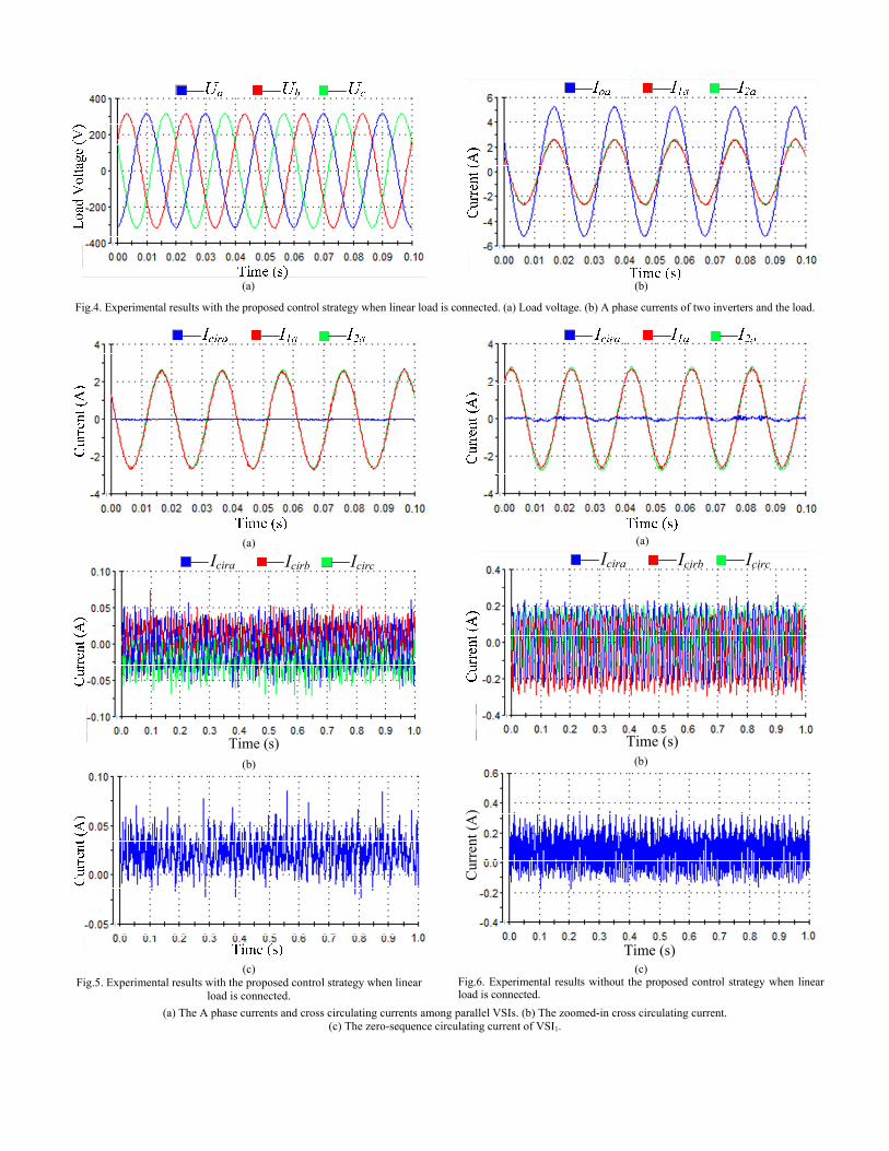
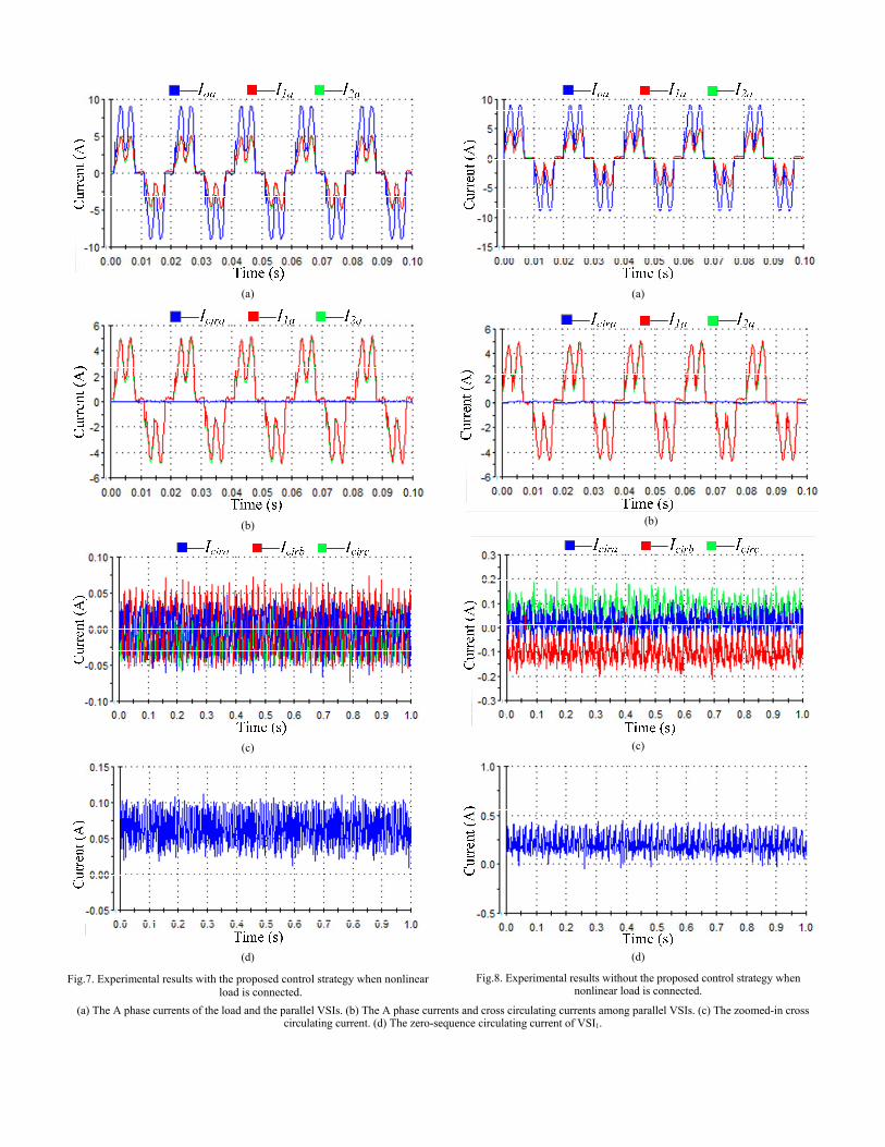
In order to verify the effectiveness of the proposed control strategy, experiments had been done with dSPACE 1006, using the proposed control strategy. Both of the linear and nonlinear loads were considered in the experiments. The nonlinear load
was a rectifier connected with a resistor and a capacitor. The maximum phase voltage of the load is 325V. The experimental results with linear load are shown in Fig.4~Fig.6, and Fig.7~Fig.8 are the experimental results when nonlinear load is connected.
With the proposed control strategy, when the parallel VSIs supplied a linear load, the maximum value of the cross circulating current is about 50 mA, the number will be about 75mA for the zero-sequence circulating current. But without the proposed strategy, the maximum value will be more than 200 mA and 300mA for the cross and zero-sequence circulating currents respectively. If the parallel inverters were sharing a nonlinear load, the maximum value of the cross and zero-sequence circulating currents is about 75 mA and 100 mA respectively. But with the conventional droop and virtual impedance control, the maximum value of the cross circulating current is more than 200 mA, the number will be about 400mA for the zero-sequence circulating current. So compared with the conventional droop and virtual impedance control method, both of the cross circulating current and the zero-sequence circulating current can be effectively suppressed using the proposed control strategy with both linear and nonlinear loads. Therefore, a better average current-sharing performance is obtained.
(a) (b)
Fig.4. Experimental results with the proposed control strategy when linear load is connected. (a) Load voltage. (b) A phase currents of two inverters and the load.
(a)
Icira Icirb Icirc
Time (s)
(b)
(c)
Fig.5. Experimental results with the proposed control strategy when linear load is connected.
(a)
Icira Icirb Icirc
Time (s)
(b)
Cur
rent
(A
)
Time (s) (c)
Fig.6. Experimental results without the proposed control strategy when linear load is connected.
(a) The A phase currents and cross circulating currents among parallel VSIs. (b) The zoomed-in cross circulating current. (c) The zero-sequence circulating current of VSI1.
(a)
(b)
(c)
(d)
Fig.7. Experimental results with the proposed control strategy when nonlinear load is connected.
(a)
(b)
(c)
(d)
Fig.8. Experimental results without the proposed control strategy when nonlinear load is connected.
(a) The A phase currents of the load and the parallel VSIs. (b) The A phase currents and cross circulating currents among parallel VSIs. (c) The zoomed-in cross circulating current. (d) The zero-sequence circulating current of VSI1.

IV. CONCLUSION
Parallel inverters are widely used for high power demand, and the average current-sharing scheme is necessary. A control strategy considering both of the cross circulating current and zero-sequence circulating current with droop and virtual impedance control is proposed in this paper. It combined the concept of droop control and the distributed control strategies. Experiments had been done when parallel-connected inverters were sharing linear or nonlinear loads. The results demonstrate that, both of the cross and zero-sequence circulating currents among the parallel VSIs can be effectively suppressed, then the average current-sharing is realized.
REFERENCES
[1] T. B. Lazzarin, G. A. T. Bauer, and I. Barbi, “A control strategy for parallel operation of single-phase voltage source inverters: Analysis, design and experimental result,” IEEE Trans. Ind. Electron., vol. 60, no. 6, pp. 2194–2204, Jun. 2013.
[2] F. Wang, Y. Wang, Q. Gao, C. wang, and Y. liu, “A Control Strategy for Suppressing Circulating Currents in Parallel-Connected PMSM Drives With Individual DC Links,” IEEE Trans. Power Electron., vol. 31, no. 2, pp. 1680-1691, Feb. 2016.
[3] D. C. Pham, S. Huang, and K. Huang, “Modeling and Simulation of Current Source Inverters with Space Vector Modulation,” in Proc. IEEE ICEMS 2010, Oct. 10–13, pp. 320 - 325.
[4] Z. Bai, Z. Zhang, and X. Ruan, “A Natural Soft-Commutation PWM Scheme for Current Source Converter and Its Logic Implementation,” IEEE Trans. Ind. Electron., vol. 58, no. 7, pp. 2772 - 2779, Jul. 2011.
[5] T. -P. Chen, “Zero-Sequence Circulating Current Reduction Method for Parallel HEPWM Inverters Between AC Bus and DC Bus,” IEEE Trans. Ind. Electron., vol. 59, no. 1, pp. 290–300, Jan. 2012.
[6] J. M. Guerrero, J. Matas, L. G. Vicuna, M. Castilla, and J. Miret, “Wireless-control strategy for parallel operation of distributed-generation inverters,” IEEE Trans. Ind. Electron., vol. 53, no. 5, pp. 1461–1470, Oct. 2006.
[7] Y. Zhang, M. Yu, F. Liu, and Y. Kang, “Instantaneous Current-Sharing Control Strategy for Parallel Operation of UPS Modules Using Virtual Impedance,” IEEE Trans. Power Electron., vol. 28, no. 1, pp. 432-440, Jan. 2013.
[8] J. M. Guerrero, L. G. Vicuna, J. Matas, M. Castilla, and J. Miret, “Output impedance design of parallel-connected UPS inverters with wireless load-sharing control,” IEEE Trans. Ind. Electron., vol. 52, no. 4, pp. 1126–1135, Aug. 2005.
[9] J. He, and Y. Li, “Analysis, Design, and Implementation of Virtual Impedance for Power Electronics Interfaced Distributed Generation,” IEEE Trans. Ind. Applica., vol. 47, no. 6, pp. 2525–2538, Nov. 2011.
[10] M. Prodanovic, T.C. Green, and H. Mansir, “Survey of control methods for three-phase inverters in parallel connection,” IEEE Conference Publication (475) 472-477.
[11] H. Cai, R. Zhao, and H. Yang, “Study on Ideal Operation Status of Parallel Inverters,” IEEE Trans. Power Electron., vol. 23, no. 6, pp. 2964–2969, Nov. 2008.