aalborg universitet a repetitive control scheme aimed...
TRANSCRIPT

Aalborg Universitet
A Repetitive Control Scheme Aimed at Compensating the 6k + 1 Harmonics for aThree-Phase Hybrid Active FilterLuo, Zhaoxu; Su, Mei; Yang, Jian; Sun, Yao; Hou, Xiaochao; Guerrero, Josep M.
Published in:Energies
DOI (link to publication from Publisher):10.3390/en9100787
Publication date:2016
Document VersionEarly version, also known as pre-print
Link to publication from Aalborg University
Citation for published version (APA):Luo, Z., Su, M., Yang, J., Sun, Y., Hou, X., & Guerrero, J. M. (2016). A Repetitive Control Scheme Aimed atCompensating the 6k + 1 Harmonics for a Three-Phase Hybrid Active Filter. DOI: 10.3390/en9100787
General rightsCopyright and moral rights for the publications made accessible in the public portal are retained by the authors and/or other copyright ownersand it is a condition of accessing publications that users recognise and abide by the legal requirements associated with these rights.
? Users may download and print one copy of any publication from the public portal for the purpose of private study or research. ? You may not further distribute the material or use it for any profit-making activity or commercial gain ? You may freely distribute the URL identifying the publication in the public portal ?
Take down policyIf you believe that this document breaches copyright please contact us at [email protected] providing details, and we will remove access tothe work immediately and investigate your claim.
Downloaded from vbn.aau.dk on: juni 25, 2018

Energies2016,9,x; doi: www.mdpi.com/journal/energies
Article
A repetitive control scheme aiming to compensate the 6k+1 harmonics for three-phase hybrid active filter Zhaoxu Luo 1, Mei Su 1, Jian Yang1,*, Yao Sun 1, Xiaochao Hou 1, and Josep M. Guerrero2
1 School of Information Science and Engineering, Central South University, Changsha 410083, China; [email protected] (Z.L.); [email protected] (M.S.);
2 Department of Energy Technology, Aalborg University, DK-9220 Aalborg East, Denmark; [email protected]
* Correspondence: [email protected] (J.Y.); Tel.: +86-189-7488-0556
Abstract: The traditional repetitive controller has relatively worse stability and poor transient performance due to the facts that it generates infinite gain at all the integer multiples of the fundamental frequency, and its control action is postponed by one fundamental period (T0). To improve these disadvantages, many repetitive controllers with reduced delay time have been proposed, which can selectively compensate the odd harmonics or 6k±1 harmonics with delay time reduced to T0/2 and T0/3,repectively. To further study in this area, this paper proposes an improved repetitive scheme implemented in stationary reference frame, which only compensates the 6k+1 harmonics (e.g. -5, +7, -11, +13) in three-phase systems and reduces the time delay to T0/6 . So compared with the earlier reduced delay time repetitive controllers, the robustness and transient performance is further improved, the waste of control effort is reduced, and the possibility of amplifying and even injecting any harmonic noises into system is avoided to the greatest extent. Moreover, the proposed repetitive scheme is used in the control of a three-phase hybrid active power filter. The experimental results validate the effectiveness of the proposed repetitive control scheme.
Keywords: repetitive control; hybrid active power filter; power quality; harmonic compensation;
PACS: J0101
1. Introduction
Recently, due to the widespread applications of distributed generations, adjustable speed drives,uncontrolled AC/DC rectifiers, and other nonlinear loads, the harmonic pollution in power systems is getting more and more serious. The passive power filter (PPF) and active power filter (APF) are the two common solutions applied to mitigate these harmonics [1-2]. PPFs have the advantages of low-cost and high-efficiency. However, they also have some inherent drawbacks. Their compensation characteristics are strongly influenced by supply impedance and they are highly susceptible to series and parallel resonances with the supply and load impedance. The APFs,which are based on the power electronics, can overcome above drawbacks of PPFs [3-4]. Additionally, APFs are more flexible and efficient compared with PPFs. But, pure APFs usually require a PWM inverter with large kilovoltampere (KVA) rating. Thus, they do not constitute a cost-effective harmonic filtering solution for nonlinear loads above 500-1000 kW[5-6]. To address this issue, hybrid active power filter (HAPF) have been developed, which are composed of small rated APF and PPF in different configurations. Among the various viable hybrid active filter topologies, parallel hybrid active filters present a cost-effective solution for harmonic filtering and reactive power compensation of high power nonlinear industrial loads, due to small rating of the active filter—2%–3% of load KVA rating [6]. Thus, they have attracted increasing attention [7-11].

Energies 2016, 9, x 2 of 18
Among various control strategies, the repetitive control, as a kind of control method based on
internal model principle, can accurately track the periodic signal or reject periodic interference.
Hence it is widely used in harmonic compensation scheme for active filters [12-15]. The traditional
repetitive control technique can generate infinite gains at all the integer multiples of the
fundamental frequency, including the odd, even harmonics and dc component. However, in most
cases, the introduction of high gain for all frequencies is not necessary, as it could waste control
effort and reduce the system robustness without improving system performance, even amplify
irrelevant signal and reinject distortions to systems [16]. Moreover, the control action of traditional
repetitive controller is postponed by one fundamental period (T0), hence the transient performance
is poorer. To improve the drawbacks above, and considering the fact that even harmonic
components do not regularly appear in power systems, literatures [16-17] propose a repetitive
control scheme aiming at compensating only the odd harmonics. It uses a negative feedback array
instead of the usual positive feedback in the traditional repetitive controller. Meanwhile, the delay
time of control action is reduced to T0/2. As a sequence, the control performance is improved and
the convergence rate is enhanced. Furthermore, among the odd harmonics, the group of 6 1 ( 0, 1, 2 )k k± = ± ± ⋅ ⋅⋅ harmonic components in electric industry are dominated due to the wide
use of uncontrolled rectifiers and six-pulse converters. Thus, many improved repetitive control
schemes aiming at compensating 6 1k ± harmonics have been developed [18-20]. For instance, in
[18] a repetitive control scheme based on the feedback array of two delay lines plus a feedforward
path is presented, which can only compensate 6 1k ± harmonics and reduce delay time to T0/3; In
[19], the authors propose a 6 1k ± repetitive control scheme in there-phase synchronous reference
frame (SRF). It has an advantage of T0/6 delay time. However, it needs complex coordinate
transformation and much more calculation in both positive-rotating and negative-rotating SRFs.
Considering in three-phase power systems, harmonic of the same frequency can be
decomposed into positive sequence, negative sequence and zero sequence. Generally speaking, a
normal balanced three-phase system mainly contains 6k+1 harmonics (such as -5, +7, -11, +13), and
rarely contains 6k-1 harmonics (such as +5, -7, +11, -13). For this reason, this paper proposes a
repetitive control scheme aiming at compensating the 6k+1 harmonics implemented in three-phase
stationary reference frame with T0/6 delay time. So that the transient performance is further
improved. The 6k+1 repetitive controller is expressed with complex-vector notation, so that the dual-input/dual-output control system (in the αβ reference frame) can be simplified into one
single-input/single-output system. Meanwhile, the general design method of Lk+M repetitive
controller is also introduced, with which a repetitive controller aiming at compensating Lk+M
harmonics can be easily deduced. Moreover, taking the transformerless parallel hybrid active filter
as controlled object, a harmonic compensating control system based on the proposed 6 1k +
repetitive control scheme is presented. Finally, the experimental results validate the effectiveness of
the 6 1k + repetitive control scheme.
2. System structure and mathematical modeling of HAPF
2.1. Topological structure analysis

Energies 2016, 9, x 3 of 18
The topology of the transformerless parallel hybrid active filter is shown in Figure 1. It consists
of a LC passive filter and a three-phase voltage source inverter (VSI). The purposes of installing the
LC filter are: 1) to provide reactive power compensating and absorb some harmonics; 2) to sustain
fundamental voltage at the point of common coupling (PCC). And the active filter (VSI) is
responsible for improving the filtering characteristics of passive filter and avoiding the undesirable
resonances with the grid. To minimize its own KVA rating, VSI doesn't participate in reactive
compensation, and the grid voltage is almost fully dropped on the capacitor in LC filter. Thus the
fundamental voltage sustained by VSI is small. So that the dc bus voltage rating of VSI can be set
very low, the KVA rating and power losses are reduced greatly. Due to the presence of VSI, LC
filter is not necessary to be accurately tuned at a certain harmonic frequency. The design objective
of LC filter is to offer a lowest possible impedance path for injecting harmonic currents, on the
premise of ensuring reactive power compensating.
Nonlinear load
sbvscv
,L RC Cav Cbv Ccv+
−
savsaisbisci
lai
lbilci
ai
bi
ci
+
−
+
−
dcC
dcv
cS bS dci
cS bS
aS
aS
avbv
cv
GridPCC
Figure 1. Topology of parallel hybrid active power filter
2.2. Mathematical modeling
According to Figure 1, the mathematical model in state-space representation for the system is
formulated as
asa Ca a a
bsb Cb b b
csc Cc c c
diL v v Ri vdtdiL v v Ri vdtdiL v v Ri vdt
= − + − + = − + − +
= − + − +
(1)
Caa
Cbb
Ccc
dvC idt
dvC idt
dvC idt
= − = −
= −
(2)
( )dcdc dc a a b b a a
dvC i S i S i S idt
= = − + +
(3)

Energies 2016, 9, x 4 of 18
where aS , bS and cS are switching functions defined by
1, ( on, )( , , )
0, ( off, )x x
xx x
when S S offS x a b c
when S S on
= =
(4)
2. System control
According to (1-2), it can be inferred that the state equation of output current ( , , )xi x a b c= is a second-order differential equation. If the output current control is implemented in dq synchronous reference frame, it needs to sample and feed back the AC capacitor voltage ( , , )Cxv x a b c= to achieve decoupling control between d-axis and q-axis. Therefore, in this paper, the output current control is implemented in αβ stationary frame, which has the advantages of no need of complex decoupling control and AC capacitor voltage sampling. The overall system control diagram is shown in Figure 2, it is mainly composed of dc-link voltage control and harmonic current tacking control. In this figure, Bpf(s) is a band-pass filter to extract the fundamental frequency component of input signal, and its expression is given by
02 2
0 0
( )sBpf s
s sγωγω ω
=+ +
(5)
where 0ω is the grid frequency; γ is the control coefficient of passband width and 0γ > .
( )fv αβ
Dc-link voltage control
PI
d
q
0
/dqT αβfqV ∗
je q
*dcV
dcv
(come from Phase-locked loop)
( )l abciabc αβ
( )li αβ1 ( )Bpf s−
( )hi αβ∗
( )abciabc αβ
( )i αβ1 ( )Bpf s− ( )hi αβ
harmonic current reference
injected harmonic current
Repetitivecontroller
( )hv αβ
harmonic current tracking
PWMmodulation
aS
aS
cS
( )v αβ
Figure 2. Overall block diagram of system control
2.1. DC-link voltage stabilisation method
Assuming that the VSI doesn't provide reactive power compensation for the load and only absorbs active power from grid to maintain its power loss. According to the power conservation principle, there is
dcdvin dc dc lossdtP C v P= + (6)

Energies 2016, 9, x 5 of 18
where inP is the active power absorbed from gird, dcdvdc dc dtC v is the power of the dc-link capacitor
and lossP is the power loss of inverter. It can be inferred from (6) that if lossP is regarded as a disturbance, dcv could be controlled by adjusting inP . In the dq synchronous reference frame (grid voltage orientation), the active power inP and reactive power inQ absorbed by VSI can be given by
2 2
sd fqin
fd sd fd fqin
V VP
XV V V V
QX
= −
− + =
(7)
where X denotes the fundamental frequency impedance of LC filter; sdV is the d-axis component of grid voltage ( 0sqV = ); fqV , fqV are the d-axis and q-axis component of VSI output fundamental
voltage, respectively. It can be inferred from (7) that inP is only regulated by fqV . Generally, fqV is small. Thus,
0inQ ≈ could be achieved when fqV is set to 0. Thus, the dc-link voltage regulator can be designed
as (8), and the corresponding bode diagram is shown in Figure 2.
( )( )
0fq p i dc dc
fd
V k k s V v
V
∗ ∗
∗
= + −
= (8)
where *dcV is the rated value of dc-link voltage; pk , ik are the parameters of PI controller.
2.2. Harmonic current tracking control
Harmonic current tracking control is the important part of system control, which contributes directly to the performance of harmonic compensating. The block diagram of current control is shown in Figure 2. Considering the case that the three-phase load current mainly contains 6k+1 harmonics, this paper presents a 6k+1 repetitive control scheme to compensate these harmonics. The detail theoretical derivation, analysis and design of proposed 6k+1 repetitive controller is given in the next section.
3. 6k+1 repetitive control scheme
3.1. internal model of 6k+1 repetitive controller
Firstly, the internal model of the wellknown traditional repetitive controller is given by
0
0( )
1
sT
t sTeRC s
e
−
−=−
(9)
where 0sTe− is the periodic time delay unit, and T0 is the fundamental period, i.e., 0 02T π ω= .
By setting the denominator 01 sTe−− in (9) equal to zero, it can be obtained that
0 ( 0, 1, 2, , )pks jk kω= = ± ± ±∞2 (10)
where pks is the pole of (9). Seen from (10), it is clear that the traditional repetitive controller has
an infinite number of poles located at 0jkω , which is the reason traditional repetitive controller has resonant peaks at every integral multiple of fundermental frequency 0ω .

Energies 2016, 9, x 6 of 18
In order to make repetitive controller with poles only located at a selected group of harmonic frequencies, a new internal model is need to be structured. Assume the order h of these harmonics meets the rule:
h Lk M= + (11) where L, M are intergers, and L is not equal to zero.
Then, the poles of the new internal model should be located at
0( ) ( 0, 1, 2, , )pks j Lk M kω′ = + = ± ± ±∞2 (12)
Moreover, to enhance the frequency selectivity, an infinite number of zeros of the new internal model that located in the midpoints between two consecutive poles are introduced as
0( 0.5 ) ( 0, 1, 2, , )zks j Lk M L kω′ = + + = ± ± ±∞2 (13)
These zeros bring another benefit that allowing bigger gains with improved performance. In order to satisfy (12-13) , the general internal model for Lk M+ harmonics can be structured
as 0
0
00
( ( 0.5 ))
( )1( )
1
s j M LT
L
g s j MT
L
eRC se
ω
ω
− +−
−−
−=
− (14)
After the substitution of L=6 and M=1 in (14), the 6k+1 internal model is given by 0
0
3 6
3 6
1( )1
Tj s
Tj s
e eRC se e
π
π
−
−
+=
−
(15)
Comparing (15) with the traditional internal model given by (9), it can be found that the delay time of 6k+1 internal model is reduced to T0/6, which means a much faster dynamic response. what's more, it should be noted that the 6k+1 internal model is expressed using the complex-vector
notation, as it contains the complex coefficient 3j
eπ
. As a consequence, the input signal of RC (s) is required to be a complex vector. The block of the proposed 6k+1 internal model is shown in Figure 3.
0
6Ts
e
( )se
3j
e
( )sy
(a)

Energies 2016, 9, x 7 of 18
( )e s ( )sy
0
6Ts
e
32
( )e s ( )sy
0
6Ts
e
12
12
12
12
32
(b)
Figure 3. Block diagram of the 6k+1 repetitive controller internal model: (a) complex-vector notation;(b) scalar
notation
Assuming that the fundermental frequcny f0 = 50 Hz, i.e., T0 = 0.02 s, the bode plot of the 6k+1 repetitive controller internal model is shown in Figure 4. As expected, the amplitude-frequency response curve shows that 6k+1 internal model has resonant peaks that located at frequency multiples 6k+1 of 50 Hz (50, -250, 350, -550, 650 Hz ...), and has notches that located at frequency multiples 6k+4 of 50 Hz (-100, 200, -400, 500 Hz ...). The phase-frequency response curve shows the phase shift is bounded between 90 and - 90 degree, and zero at the peaks and notches.
-600 -400 -200 0 200 400 600 800-400
-200
0
200
400
Frequency (Hz)
Mag
titud
e (d
B)
-600 -400 -200 0 200 400 600 800-100
-50
0
50
100
Phas
e (d
eg)
Figure 4. Bode plot of the proposed repetitive controller internal model.
3.2. Fractional delay compensation
In a practical application, the implementation of repetitive control scheme is usually performed in the digital form. Using the transformation ssTz e= , (15) can be discretized and its expression in discrete time domain is given by
0
0
3 6
3 6
1( )1
sTs
Nj
Nz e j
e zRC ze z
π
π
−
= −
+=
−
(16)

Energies 2016, 9, x 8 of 18
where Ts is the sampling period, and 0 0 sN T T= (the number of samples per fundamental period ).
In most cases, the sampling frequncy sf ( 1s sf T= ) is a fixed rate(e.g. 10 kHz,12.8 kHz, 20 kHz), and the grid frequecny detected by PLL is variabe in a certain range (e.g. 49~51Hz). Thus,
0 6N is usually non-interger. Let
0( )6
ND d D dz z z z
− − + − −= = ⋅ (17)
where D and d are the integral and fractional parts of 0 6N , repectively. In a common implementation, 60N
z− is approximately treated as Dz− and performed by
reserving D memory locations, with the fractional order part dz− neglected. But, this will cause the resonant peaks to deviate from the harmonic frequencies. As a consequence, the harmonic comperseation performance could be degraded.
To address this problem, fractional delay (FD) filters have been usd as approximations of dz− . The magnitude-frequency and phase-frequency characteristics of dz− can be given by
1d
ds
z
z d Tω
−
−
=∠ = −
(18)
Thus, it requires that FD filters should have a unit gain and linear phase in the low-middle frequencies, and acheive a high attenuation rate in the high frequencies to enhance the system stablity.
In the condition of 1 1 1z− − < (i.e. (3 ) (3 )s sT Tπ ω π− < < ), with the use of the Taylor
expansion, dz− can be expressed as
1 1 1( 1) ( 1)(1 1) 1 ( 1) ( 1)!
d d nd d d nz z d z zn
− − − −− − += + − = + − + + −
22
(19)
Specifically, choose the first-order Taylor expansion of dz− as a FD filter, that is
1( ) 1Fd z d dz−= − + (20)
Figure 5 shows the bode plot of ( )Fd z , with 78.125 ssT µ= , d =0.2, 0.5 and 0.8, respectively. It can be seen that ( )Fd z has the low-pass filter nature. In low frequecnies, ( )Fd z has a well linear phase approximated to the ideal value. However, the main disadvantages of ( )Fd z are that the cutoff frequecny is too high (greater than 3000 Hz), and it changes with the value of d. Only when d=0.5, ( )Fd z achieves the lowest cutoff frequecny and best linear phase.

Energies 2016, 9, x 9 of 18
-25
-20
-15
-10
-5
0
Mag
nitu
de (d
B)
Frequency (Hz)1000 2000 3000 4000 5000 6000
-180
-135
-90
-45
0P
hase
(deg
)
0.2,0.8d =
0.5d =
0.5d =
0.2d =
0.8d =
ideal value
-3db
ideal value
ideal value
Figure 5. Bode plot of Fd(z)
To overcome above issue, this paper presents a FD filter ( )Q z by cascading Fd(z) with a zero-phase digital low-pass filter, i.e.,
( ) ( ) ( )Q z Fd z M z= (21) where ( )M z is the zero-phase digital low-pass filter used to low the cut-off frequency and Increase the attenuation rate in high frequecnies. Its expression is given as
11 0 1( ) ( )nM z a z a a z−= + + (22)
where 0 1, 0a a > and 0 12 1a a+ = ; n is the order of filter. Although ( )Q z is noncausal, the time delay term Dz− makes it applicable. After the
fractional delay compseation, (16) should be revised as
3
3
1 ( )( )1 ( )
j D
j D
e Q z zRC ze Q z z
π
π
−
−
+=
−
(23)
3.3. Design of 6k+1 repetitive controller
Figure 6 shows the block diagram of the harmonic current tracking control. This paper adopts a plug-in repetive controller structure in the control loop,where the PI controller is used to enhance the stability and improve dynamic response, and the repetive controller is used to eliminate the steady-state error.
*hi
ck ( )P z hihve
PI(z) ( )P z′
RC(z) ( )fG z
Figure 6. Block diagram of harmonic current tracking control
In Figure 6, P(z) is the plant of current control. According to (1-2), its expression in continuous domain can be obtained as

Energies 2016, 9, x 10 of 18
1( )1
P sLs R Cs
=+ +
(24)
Obviously, P(s) is a second-order system. To modify the characteristic of P(s), a method of
output current status feedback is used. Accoding to Figure 6, the modified plant expression is given
by ( ) 1( )
( ) 11 ( )c
cc
c c c
k P sP s k RLk P s sk k k Cs
′ = =++ + +
(25)
Equation (25) reveals that ( )P s′ can be viewed as the R becomes to 1 ( ck R ), while L, C
become 1 ck and ck times of its original values in P(s), respectively. The bode plots of P(s) and
( )P s′ are shown in Figure 7, with 3 mHL = , 90 FC µ= , 0.1 R = Ω . As seen, ( )P s′ has cancelled
the resonant peak appeared in P(s), and presents the characteristics of a band-pass filter. The
passband width depends on the value of ck . A larger ck leads to bigger passband width and
smaller phase lead/lag.
-40
-20
0
20
Mag
nitu
de (d
B)
200 400 600 800 1000 1200 1400 1600-90
-45
0
45
90
Pha
se (d
eg)
Frequency (Hz)
( )P s
( )P s
0
( ) with 3cP s k′ = ( ) with 6cP s k′ =
( ) with 3cP s k′ =
( ) with 6cP s k′ =
Figure 7. Bode plots of P(s) and ( )P s′
In Figure 7, without the repetitive controller, the tracking error e between the reference *hi
and output hi is
*0
1( )1 ( ) ( ) hz
PI z P z=
′+e i
(26)
where ( )PI z should be designed to guarantee the stability of 0 ( )ze .
With the proposed 6k+1 repetitive controller, the tracking error e can be written as

Energies 2016, 9, x 11 of 18
0
3
03
1( ) ( )1 ( ) ( ) ( )
1 (1 ( ) )( )2
1 (1- ( ) ( )) (1 ( ) ) 2
f
j D
j Df
z zH z G z R z
e Q z zzH z G z e Q z z
π
π
−
−
=+
−=
− +
e e
e (27)
where ( )fG z is the compensation function, and
( )( )1 ( ) ( )
P zH zPI z P z
′=
′+
(28)
By the small gain theorem, the sufficient condition for ensuring (27) stable can be given as
3(1- ( ) ( )) (1 ( ) ) 2 1j D
fH z G z e Q z zπ
−+ < (29)
Clearly, 3(1 ( ) ) 2 1j De Q z zπ
−+ ≤ is true. To make (29) true, it only needs 1- ( ) ( ) 1fH z G z <
being satisfied. Thus, ( )fG z can be chosen as
1 1( )( ) 1fG s
H s sτ= ⋅
+ (30)
where ( )fG s and ( )H s are the functions of ( )fG z and ( )H z in Laplace domain, respectively;
1 ( 1)sτ + is a low-pass filter.
Moreover, on the premise of system stability, it can be derived that the numerator of (27) has
such a steady-state relationship:
0 0(6 1) (6 1)31 ( ) 0s sj j k T j k DTe Q e eπ
ω ω+ − +− = (31)
Equation (31) indicates that the 6k+1 repetitive control scheme can eliminate the steady-state
error of 6k+1 harmonics tracking in D+d Ts (i.e., T0/6), which means the proposed repetitive control
scheme could has a much faster transient state response than the traditional one.
4. Experimental results
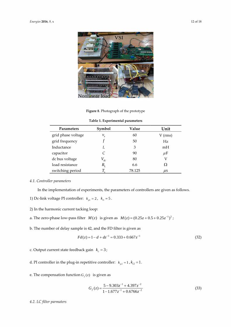
To validate the correctness and effectiveness of the proposed 6k+1 repetitive control scheme, a
prototype of three-phase parallel hybrid APF is built in lab, which is shown in Figure 8. The control
system is realized by a combination of digital signal processor TMS320F28335 and field
programmable gate array FPGA EP2C8T144C8N. The power switches use three Infineon IGBT
modules and the drive circuit uses M57962L driver chips. The non-linear load used in the
experiments is a three-phase diode rectifier bridge with resistive load. The overall experimental
parameters are given in Table 1.
Energies 2016, 9, x 12 of 18
VSI
PPF
Nonlinear load
Figure 8. Photograph of the prototype
Table 1. Experimental parameters
Parameters Symbol Value Unit grid phase voltage sv 60 V (rms) grid frequency f 50 Hz Inductance L 3 mH capacitor C 90 Fµ dc bus voltage dcV 80 V load resistance LR 6.6 Ω switching period sT 78.125 sµ
4.1. Controller parameters
In the implementation of experiments, the parameters of controllers are given as follows.
1) Dc-link voltage PI controller: 1 2pk = , 1 5ik = .
2) In the harmonic current tacking loop:
a. The zero-phase low-pass filter ( )M z is given as 1 2( ) (0.25 0.5 0.25 )M z z z−= + + ;
b. The number of delay sample is 42, and the FD filter is given as
1 1( ) 1 0.333 0.667Fd z d dz z− −= − + = + (32)
c. Output current state feedback gain 3ck = ;
d. PI controller in the plug-in repetitive controller: 2 1pk = , 2 1ik = .
e. The compensation function ( )fG z is given as
1 2
1 25 9.303 4.397( )1 1.677 0.6766f
z zG zz z
− −
− −
− +=
− + (33)
4.2. LC filter parmaters
Energies 2016, 9, x 13 of 18
As the non-linear load used in this paper is a three-phase diode rectifier bridge with resistive
load,the 5th, 7th, 11th, 13th harmonic currents are dominated in load current. Assume that the load
harmonic currents are fully compensated by the hybrid APF, the voltage drop across the LC filter
by the injected compensating harmonic current is
1 1
1 1( ) ( )m mh lh m lh m
m mm m
v i L I LC C
ω ωω ω> >
= − ≤ −∑ ∑ (34)
where mlhi is the m-th order harmonic component of load current, and m
lhI is the amplitude of mlhi .
For the hybrid APF, the design objective of LC filter is to offer a lowest possible impedance
path for injecting harmonic currents, in other words, to minimize the voltage drop hv . Thus, the
dc-link voltage rating of VSI can be minimized.
Then, an optimization function can be given as
min5,7,11,13 5,7,11,13
1 1( ) ( )mh m f m m
m mm m
f I L I HD LC C
ω ωω ω= =
= − = ⋅ −∑ ∑ (35)
where mHD is the individual m-th order harmonic distortion rate, and lfI is the amplitude of
fundamental component in load current.
The capacitor C in LC filter can be chose by the rule as follow:
213C sQ CVω= (36)
where CQ is the reactive power demanded by load, 1ω is the grid frequency, sV is the grid
voltage amplitude.
Assume the capacitor C has been determined, such as C=90uf. According to Fig.11(b), it can
obtained that 5 22.4%HD = , 7 8%HD = , 11 5.7%HD = and 13 2.6%HD = . Substituting the above
parameters into (32), the optimal inductor L can be obtained as L=2.8 mH. So we choose L=3 mH for
the hybrid APF experimental prototype without loss of much performance, and the resonant
frequency of LC filter is 306 Hz.
4.3. Experimental results
Figure 9 shows the dynamic behaviour of dc-link capacitor voltage in start-up process. To avoid the inrush current caused by capacitors, the series-resistance soft-start mode is used in experiments. Specifically, when 60 Vdc setv V≤ = , the IGBTs are turned off, the capacitors are charged up with small current due to the series-resistance ; When dc setv V> , the series-resistance is bypassed and then the PWM pulses will be activated. dcv reaches the setting value 80 V in the steady state, which verifies the correctness of the dc voltage control strategy.

Energies 2016, 9, x 14 of 18
dcv
setV
Figure 9. Start-up process of dc-link voltage
To validate the static and dynamic performances of the proposed 6k+1 repetitive control scheme, the related experimental results are shown in Figure 10-13. For the sake of simplicity, only the a-phase waveforms are displayed.
Figure 10 shows the harmonic compensation results when nonlinear load is disconnected ( 0lai = ). As seen, sa ai i= , and sai is almost the reactive power current provided by LC filter. The waveform of ai is sinusoidal with less distortion, which indicates that the proposed repetitive control scheme can well suppress the undesired harmonic components.
sav
sai
ai
lai
Figure 10. Harmonic compensation results with nonlinear load disconnected
Figure 11-12 show the steady-state harmonic compensation results with and without fractional
delay compensation when the nonlinear load is connected, respectively. In Figure 11, the total
harmonic distortion (THD) of the source current sai is reduced to 3.8% from 24.8% (THD of the
load current), and the distortion ratio of 5th, 7th, 11th and 13th harmonics in sai are reduced to 2.3%,
1.3%, 1.6% and 1.2%, respectively. As a contrast, the THD of sai is 4.9% in Figure 12. These
comparison experiment results demonstrate the good static performance of 6k+1 repetitive
controller and effectiveness of the fractional delay compensation.

Energies 2016, 9, x 15 of 18
sai
lai
ai
(a)
(b)
Figure 11. Harmonic compensation results with FD compensation: (a) source (L1), compensating
(L2), load (L3) current waveforms ; (b) harmonic distortion rate graph.
sai
lai
ai
(a)

Energies 2016, 9, x 16 of 18
(b)
Figure 12. Harmonic compensation results without FD compensation: (a) source (L1), compensating
(L2), load (L3) current waveforms ; (b) harmonic distortion rate graph.
Also, to highlight the effectiveness of the 6k+1 repetitive control scheme, the harmonic
compensation results by only the LC filter is shown in Figure 13. As seen, the source current is still
highly distorted after the compensation of the LC filter, with a THD of 15.9%. The main reasons are
that the resonant frequency of LC filter is not precisely tuned at a domain harmonic frequency, and
the performance of LC filter seriously depends on the internal resistance of grid source.
sai
lai
ai
(a)
(b)
Figure 13. Harmonic compensation results by only the LC filter: (a) source (L1), compensating (L2),
load (L3) current waveforms ; (b) harmonic distortion rate graph.
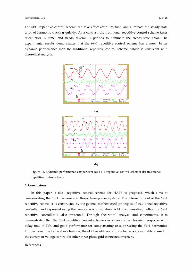
To verify the dynamic performance of the 6k+1 repetitive control scheme, Figure 14 shows
the comparison experimental results of the proposed and traditional repetitive control schemes in
transient process. As seen, before the time 1t , the harmonic compensation function is not enabled,
ai is only the reactive power current provided by LC filter with sinusoidal waveform, and sai is
distorted by the load harmonics. At the time 1t , the harmonic compensation function is enabled.
Energies 2016, 9, x 17 of 18
The 6k+1 repetitive control scheme can take effect after T0/6 time, and eliminate the steady-state
error of harmonic tracking quickly. As a contrast, the traditional repetitive control scheme takes
effect after T0 time, and needs several T0 periods to eliminate the steady-state error. The
experimental results demonstrates that the 6k+1 repetitive control scheme has a much better
dynamic performance than the traditional repetitive control scheme, which is consistent with
theoretical analysis.
sai
lai
ai
0
6T
1t
(a)
sai
laiai
1t
0T
(b)
Figure 14. Dynamic performance comparison: (a) 6k+1 repetitive control scheme; (b) traditional
repetitive control scheme
5. Conclusions
In this paper, a 6k+1 repetitive control scheme for HAPF is proposed, which aims at
compensating the 6k+1 harmonics in three-phase power systems. The internal model of the 6k+1
repetitive controller is constructed by the general mathematical principles of traditional repetitive
controller, and expressed using the complex-vector notation. A FD compensating method for 6k+1
repetitive controller is also presented. Through theoretical analysis and experiments, it is
demonstrated that the 6k+1 repetitive control scheme can achieve a fast transient response with
delay time of T0/6, and good performance for compensating or suppressing the 6k+1 harmonics.
Furthermore, due to the above features, the 6k+1 repetitive control scheme is also suitable to used in
the current or voltage control for other three-phase grid-connected inverters.
References

Energies 2016, 9, x 18 of 18
1. Singh, B.; Al-Haddad, K.; Chandra, A. A review of active filters for power quality improvement. IEEE Trans. Ind. Electron. 1999, 46, 960−971.
2. Peng F.Z. Application issues of active power filters. IEEE Industry Applications Magazine 1998, 4, 21-30. 3. Trinh, Q.N., Lee, H.H. An advanced current control strategy for three-phase shunt active power filters.
IEEE Trans. Ind. Electron. 2013, 60, 5400–5410. 4. Cao, W.; Liu, K.; Ji, Y.; Wang, Y.; Zhao, J. Design of a Four-Branch LCL-Type Grid-Connecting Interface
for a Three-Phase, Four-Leg Active Power Filter. Energies 2015, 8, 1606-1627. 5. Bhattacharya, S.; Divan, D.M. Active filter solutions for utility interface of industrial loads. In Proceedings
of the 1996 International Conference on Power Electronics, Drives and Energy Systems for Industrial Growth, New Delhi, India, 1996; pp. 1078-1084.
6. Bhattacharya, S.; Cheng P.T.; Divan, D. M. Hybrid solutions for improving passive filter performance in high power applications. IEEE Trans. Ind. Appl. 1997, 33, 732-747.
7. Inzunza, R.; Akagi, H. A 6.6-kV transformerless shunt hybrid active filter for installation on a power distribution system. IEEE Trans. Power Electron. 2005, 20, 893−900.
8. Lee, T.L.; Wang, Y.C.; Li, J.C. Hybrid Active Filter With Variable Conductance for Harmonic Resonance Suppression in Industrial Power Systems. IEEE Trans. Ind. Electron. 2015, 62, 746−756.
9. Luo, Z.X.; Su, M.; Sun, Y.; Zhang, W.; Lin, Z.L. Analysis and control of a reduced switch hybrid active power filter. IET Power Electron. 2016, 9, 1416-1425.
10. Luo, A.; Xu, X.Y.; Fang, H.H. Feedback-Feedforward PI-Type Iterative Learning Control Strategy for Hybrid Active Power Filter With Injection Circuit. IEEE Trans. Ind. Electron. 2010, 57, 3767-3779.
11. Deng, Y.P.; Tong, X.Q,; Jia, H. A Bidirectional Control Principle of Active Tuned Hybrid Power Filter Based on the Active Reactor Using Active Techniques. IEEE Trans. Ind. Inform. 2015, 11, 141-154.
12. Zou, Z.X.; Zhou, K.L.; Wang, Z. Frequency-Adaptive Fractional-Order Repetitive Control of Shunt Active Power Filters. IEEE Trans. Ind. Electron. 2015, 62, 1659−1668.
13. Sun, J.J.; Gong, J.W.; Chen, B.F. Analysis and design of repetitive controller based on regeneration spectrum and sensitivity function in active power filter system. IET Power Electron., 2014, 7, 2133−2140.
14. Miret, J.; Castilla, M.; Matas, J. Selective Harmonic-Compensation Control for Single-Phase Active Power Filter With High Harmonic Rejection. IEEE Trans. Ind. Electron. 2009, 56, 3117−3127.
15. Grino, R.; Cardoner, R.; Costa-Castelló, R. Digital Repetitive Control of a Three-Phase Four-Wire Shunt Active Filter. IEEE Trans. Ind. Electron. 2007, 54, 1495-1503.
16. Costa-Castelló, R.; Grino, R.; Fossas, E. Odd-harmonic digital repetitive control of a single-phase current active filter. IEEE Trans. Power Electron. 2004, 19, 1060−1068.
17. Escobar, G.; Martinez, P.R.; Leyva-Ramos, J. A Negative Feedback Repetitive Control Scheme for Harmonic Compensation. IEEE Trans. Ind. Electron. 2006, 53, 1383−1386.
18. Escobar, G.; Hernandez-Briones P.G.; Martinez P.R. A Repetitive-Based Controller for the Compensation of 6l±1 Harmonic Components. IEEE Trans. Ind. Electron. 2008, 55, 3150−3158.
19. Chen, D.; Zhang, J.M.; Qian, Z.M. Research on fast transient and 6n ± 1 harmonics suppressing repetitive control scheme for three-phase grid-connected inverters. IET Power Electron. 2013, 6, 601−610.
20. Escobar, G.; Hernandez-Gomez, M.; Valdez-Fernandez, A.A. Implementation of a 6n ± 1 Repetitive Controller Subject to Fractional Delays. IEEE Trans. Ind. Electron. 2015, 62,444−452.
© 2016 by the authors. Submitted for possible open access publication under the terms and conditions of the Creative Commons Attribution (CC-BY) license (http://creativecommons.org/licenses/by/4.0/).