aalborg universitet fast link adaptation for mimo-ofdm...
TRANSCRIPT

Aalborg Universitet
Fast Link Adaptation for MIMO-OFDM
Jensen, Tobias Lindstrøm; Kant, Shashi; Wehinger, Joachim; Fleury, Bernard Henri
Published in:I E E E Transactions on Vehicular Technology
DOI (link to publication from Publisher):10.1109/TVT.2010.2053727
Publication date:2010
Document VersionEarly version, also known as pre-print
Link to publication from Aalborg University
Citation for published version (APA):Jensen, T. L., Kant, S., Wehinger, J., & Fleury, B. H. (2010). Fast Link Adaptation for MIMO-OFDM. I E E ETransactions on Vehicular Technology, 59(8), 3766 - 3778 . DOI: 10.1109/TVT.2010.2053727
General rightsCopyright and moral rights for the publications made accessible in the public portal are retained by the authors and/or other copyright ownersand it is a condition of accessing publications that users recognise and abide by the legal requirements associated with these rights.
? Users may download and print one copy of any publication from the public portal for the purpose of private study or research. ? You may not further distribute the material or use it for any profit-making activity or commercial gain ? You may freely distribute the URL identifying the publication in the public portal ?
Take down policyIf you believe that this document breaches copyright please contact us at [email protected] providing details, and we will remove access tothe work immediately and investigate your claim.
Downloaded from vbn.aau.dk on: maj 20, 2018

(c) 2010 IEEE. Personal use of this material is permitted. Permission from IEEE must be obtained for all other users, including reprinting/ republishing this material for advertisingor promotional purposes, creating new collective works forresale or redistribution to servers or lists, or reuse of anycopyrighted components of this work in other works. 1
Fast Link Adaptation for MIMO-OFDMTobias Lindstrøm Jensen,Student Member, IEEE, Shashi Kant,
Joachim Wehinger,Member, IEEE, and Bernard H. Fleury,Senior Member, IEEE
Abstract—We investigate link quality metrics (LQMs) basedon raw bit-error-rate, effective signal-to-interference-and-noise-ratio, and mutual-information (MI) for the purpose of fastlink adaptation in communication systems employing orthogonalfrequency division multiplexing and multiple-input multi ple-output (MIMO) antenna technology. From these LQMs thepacket-error-rate (PER) can be estimated and exploited to selectthe modulation and coding scheme (MCS) among a class ofcandidate MCSs that achieves the maximum throughput for thecurrent channel state under a specified target PER objective.We propose a novel MI-based LQM and compare the PER-estimation accuracy obtained with this LQM with that result ingfrom using other LQMs by means of comprehensive Monte Carlosimulations. Search methods for the MCS in the class mostsuitable for a given channel state are presented. An algorithmfor obtaining a practical upper bound on the throughput ofany link adaptation scheme is proposed. The investigated LQMsare applied to the IEEE 802.11n standard with a 2x2 MIMOconfiguration and practical channel estimation. The proposedMI-based LQM yields the highest PER estimation accuracy andits throughput shows only1.7dB signal-to-noise-ratio (SNR) losswith respect to the upper bound, but up to 9.5dB SNR gaincompared to the MCS maximizing the throughput for the currentnoise variance.
Index Terms—Adaptive modulation and coding, link adap-tation, link quality metrics, channel state information, fading,feedback delay, OFDM, MIMO, PER estimation.
I. I NTRODUCTION
The sub-carriers transmitted by a multiple-input multiple-output (MIMO) orthogonal frequency division multiplexing(OFDM) system across a time-varying frequency-selectivechannel are received with a quality level that varies overtime, frequency and spatial streams. This knowledge can beexploited in the transmitter to adjust the modulation and cod-ing scheme (MCS) in such a way that high-order modulationsand high coding rates are used in situations of goodchannelstate. This can be accomplished by the receiver identifying,among an indexed list of candidate MCSs, the best MCS forthe currentchannel stateand feeding the index of this MCSback to the transmitter. It was shown in,e.g., [1] that adaptivemodulation and coding increases the throughput of a wirelesscommunication system tremendously. The key elements in fastlink adaptation (FLA) are estimation of the packet-error-rate(PER) for different candidate MCSs and selection of the MCS
This work was sponsored by Wipro-NewLogic Technologies, Sophia-Antipolis, France, email:[email protected]. Parts of this workwere presented at the IEEE Int. Conf. on Communications, May19–23, 2008, Bejing, China. T. L. Jensen and B. H. Fleury arewith Dept. of Electronic Systems, Aalborg University, Denmark, email:[email protected] and [email protected], respectively. S. Kant is withST-Ericsson AT AB, LTE & 3G Modem Solutions, Lund, Sweden,email: [email protected]. J. Wehinger is with Infi-neon Technologies AG, Wireless Solutions, Neubiberg, Germany, email:[email protected].
that maximizes the throughput with the constraint that the timeaverage PER lies below a specified target value. FLA alsoincludes a time critical aspect because the selection of thebest MCS for the current channel state may become obsoleteas this state changes.
In systems employing MIMO OFDM antenna techniques,the main difficulty of PER estimation arises due to the unequalSNR levels in the different sub-carriers, as well asin thespatial streams when they are employed. This occurs since(i) the individual sub-carriers undergo different attenuationsdue to frequency selectivity and (ii) the ability of the receiverto separate multiple spatial streams depends on the condition-number of the MIMO channel matrix. The particularpatternof post-processing SINR values of the differentsub-carriersinduced by thechannel stateand the choice of the symboldetector strongly influence the decoder performance.However,the relationship between the post-processing SINR levels andthe resulting bit-error-rate (BER) or PER after decoding cannotbe expressed in a simple form [2].Hence, one has to resort toa simple yet accuratemappingwhich provides an estimate ofthe PER as a function of the SINR levels.
The very sameproblemis of fundamental importance forsystem level simulations in cellular communications wheretheperformance of a multitude of individual links are computedwithout actually simulating the transmission procedure oftheindividual bits. The latter approach would require too muchcomputing effort to determine the overall system performance.The goal is to identify an appropriate physical layer abstractionthat characterizes the instantaneous PER behaviour of theMIMO-OFDM transceiver for the current state of the timeand frequency-selective channel. In UMTS-technology, basedon CDMA, the assumption is that the instantaneous post-processing SINRs can be averaged (average value interface)or at least quantized using a few quantization levels [3]. Thisrequires that the channel transfer function fades slowly versusfrequency. Then the approach allows for accurate PER estima-tion results. However, in OFDM, multipath propagation causesa selective attenuation of the individual sub-carriers and, as aresult, individual code symbols experience different SINRs.Hence, other methods have to be applied to supply reliableBER/PER estimation.One-dimensional mappings exhibit lowcomplexity, while guaranteeing good performance [2]. Analternative is to use two-dimensional mappings that yieldsthe PER as a function of the mean and the variance of theSINR levels [4], [5]. However, the resulting gain in accuracyis small according to [2], which shows that the gap betweenoptimal performance and the performance achieved by one-dimensional mappings is minor. Our simulations show asimilar behaviour (see Fig. 7).Thus, FLA algorithms using onedimensional mappings almost exhaust the maximal theoretical

2(c) 2010 IEEE. Personal use of this material is permitted. Permission from IEEE must be obtained for all other users, including reprinting/ republishing this material for advertisingor promotional purposes, creating new collective works forresale or redistribution to servers or lists, or reuse of anycopyrighted components of this work in other works.
performance improvement and the additional gain achievableby using more complex techniques is minor. This motivatesthe interest in one-dimensional mappings in FLA.
Robust one-dimensional mappings have been widely stud-ied in the literature, considering methods such as uncodedBER/RawBER [6], effective SNR [7], mutual-information(MI) [8], [9] and PER indicator [10]. We propose a novellink quality metric (LQM) for MIMO-OFDM to be used forFLA. We call it mean MI bit mapping (MMIBM). We comparethis metric with three other metrics, namely MI effective SNR(MIESM), effective SNR (EESM) and RawBER. We assess theestimation accuracy of allfour metrics for a large number ofrealizations of the (frequency) transfer function of frequency-selective channels exhibiting different delay spreads. Wecom-pare the effectiveness of these metrics by realistic throughputlink-level simulations including channel estimation and feed-back delay. We extend the investigations in [11] by comparingfurther metrics, presenting a solution to problems occurringwith multiple packet lengths, and addressing the importantissue of how to obtain accurate mappings.In contrast to [12]we include results on the PER estimation accuracy, obtain anexact expression for the MI between the coded bits and thelog-likelihood ratios (LLRs), and provide comparison amongstate-of-the-art PER estimation methods, as opposed to theless accurate instantaneous SNR method [2]. Furthermore,we develop a methodology to obtain an upper bound for thethroughputof any link adaptation (LA) algorithm.A similarupper bound was independently proposed in [13]. However, weshow that in order to obtain this bound it is only necessary toevaluate an ordered subset of the candidate MCSs instead ofall candidate MCSs as done in [13]. We also prove the boundand study its tightness. In particular, we analyse the conditionsfor which the FLA algorithm can achieve the bound.
Notation
We denote vectors by bold lower case letters,e.g., x, y,and matrices by bold upper case letters,e.g., H, G. Theconjugate transpose of the matrixA is denoted byAH. Theelement in thei-th row and j-th column of A is denotedas [A]i,j . TheQ × Q identity matrix is written asIQ. Theexpectation operatoris denoted byE· andC is the set ofcomplex numbers.
II. SYSTEM MODEL
We choose the IEEE 802.11n standard asa concrete ex-ample for the system model. However, other systems, likeIEEE 802.16d/e or 3GPP-LTE, can be described in a similarway. The setup common to these systems is depicted inFig. 1. This figure shows the simplified block diagram ofa MIMO bit-interleaved coded modulation (BICM) OFDMsystem equipped withNT transmit antennas andNR receiveantennas. In the IEEE 802.11n system, the information bitstreamb is encoded using a convolutional encoder withgenerators[133, 171] in octal representation and basic coderate Rc = 1/2. The coded bit stream may be punctured toincrease the code rate to2/3, 3/4 or 5/6, depending on theused MCS. The stream of interleaved and spatially parsed
bits is mapped to a stream of complex symbols using Graymapping. Supported sub-carrier modulation formats are BPSK,QPSK, 16QAM and 64QAM. The candidate MCSs availableare enumerated according to a certain order. In the sequel,Ωdenotes the index set of the MCSs in this list. By convention,the term MCS might designate either the MCS scheme itselfor its index in Ω. The available MCSs for single-streamand dual-stream transmission are listed with their index inTable I. Their maximum throughput is reported in the columns“Throughput”. BICM schemes using different coding andmodulation per stream in multi-stream transmission are givenin [14].
The streams of complex symbolsx are modulated inan OFDM format with NSD = 52 data sub-carriers of312.5 kHz bandwidth. The total bandwidth of the OFDMsignal is 20MHz. The relationship for thek-th sub-carrier,k = 1, . . . , NSD, between the input of the spatial expansionscheme and the output of the OFDM receiver in Fig. 1 is
y[k] = H [k]x[k] + n[k] , (1)
wherey[k] ∈ CNR andx[k] ∈ CNSS are the received signalvector and the transmitted symbol vector respectively for sub-carrierk andn[k] ∈ CNR is a complexzero-meanGaussiannoise vector with covariance matrixσ2
nINR. The variableNSS
denotes the number of spatial streams andH[k] ∈ CNR×NSS
describes the effective channel matrix, including the channeltransfer function, the cyclic delay diversity (CDD) and thespatial expansion [14] for sub-carrierk. Spatial expansiontransmitsNSS symbol streams overNT transmit antennas,whereNSS ≤ NT. When spatial multiplexing is employed,NSS = NT. When either beamforming or Alamouti space-time coding is applied,NSS < NT. The CDD transmitsa cyclicly delayed OFDM symbol waveform through eachtransmit antenna in order to obtain frequency diversity at thereceiver side.
An unbiased linear minimum mean square error (MMSE)estimator is used to recover the transmitted symbol from thereceived signaly[k]:
x[k] = GH[k]y[k] . (2)
TheNR ×NSS matrix G[k] =[G1[k],G2[k], . . . ,GNSS
[k]]
has columns given by
Gj [k] =1
HHj [k]
(H[k]HH[k] + σ2
nINR
)−1Hj [k]
·(H[k]HH[k] + σ2
nINR
)−1Hj [k] , (3)
j = 1, 2, . . . , NSS, with Hj [k] denoting the columns ofH[k], i.e., H[k] = [H1[k],H2[k], . . . ,HNSS
[k] ]. Notice thatthe linear biased MIMO-MMSE corresponds to (3) with theexpression in the denominator set to one. The post-processingsignal-to-interference-and-noise ratio (SINR) at the output ofthe linear MMSE estimator for thej-th stream andk-th toneis given by [15]
γj [k] =1[(
Es
σ2nNT
HH[k]H [k] + INSS
)−1]
j,j
− 1 , (4)

3
OFDMTx
OFDMTx
SpatialParser
MapperSymbol
MapperSymbol
LLRsDepuncturerDecoder
MaxLogDemapper
MaxLogDemapper
OFDMRx
ExpansionDe-
per tone
MMSEper tone
OFDMRx
yx
MMSE
b L(c) Deparser
SpatialBitsInformationDecoded
Spatial
Π−1
NR
1
NSS
1
CodedBits
PuncturerEncoderb c
InformationBits
Expansion
SpatialΠ
x
Symbols(Complex)
NT
1 1
NSS
Fig. 1. Block diagram of a MIMO-OFDM system employing BICM.
TABLE IMCSS WITH THEIR INDICES AND ACHIEVABLE THROUGHPUTS FOR SINGLE-STREAM AND DOUBLE-STREAM (IN PARENTHESES) TRANSMISSION WITH
EQUAL SUB-CARRIER MODULATION. AN 800 ns GUARD INTERVAL IS USED IN IEEE 802.11n [14].
Indexm Sub-carrier modulation Rc Throughput [Mbps] Indexm Sub-carrier modulation Rc Throughput [Mbps]
0 (8) BPSK 1/2 6.5 (13.0) 4 (12) 16QAM 3/4 39.0 (78.0)1 (9) QPSK 1/2 13.0 (26.0) 5 (13) 64QAM 2/3 52.0 (104.0)2 (10) QPSK 3/4 19.5 (39.0) 6 (14) 64QAM 3/4 58.5 (117.5)3 (11) 16QAM 1/2 26.0 (52.0) 7 (15) 64QAM 5/6 65.0 (130.0)
k = 1, 2, . . . , NSD, j = 1, 2, . . . , NSS, with Es/σ2n denoting
the SNR measured at the ports of each receive antenna. AMaxLog symbol demapper is used to generate log-likelihoodratios (LLRs) for the coded bits, which are then multiplexedinto a single streamL(c). This stream is de-interleaved andde-punctured before it is fed to a Viterbi decoder that computesthe information bit estimatesb. In this paper we focus onthe case withNT = NR = 2 antennas. The IEEE ChannelModel B (root mean square (RMS) delay spread15 ns, excessdelay spread80 ns) and Channel Model E (RMS delay spread100 ns, excess delay spread730 ns) with 20MHz system-bandwidth are used [16].
III. FAST L INK ADAPTATION
The objective of FLA is to exploit the varyingchannel stateto increase the throughput of the system, while maintainingsome target PER (PERtarget). The FLA algorithm employedin the receiver feeds the index of the selected MCS back to thetransmitter. This MCS feedback (MFB) response may occurbased upon request from the transmitter.
The FLA algorithm considers thechannel stateinformationvia the post-processing SINRs of all spatial streams andsub-carriersΓ =
[γj [k]
]j=1,...,NSS; k=1,...,NSD
. For a givenMCS m, the FLA algorithm computes a scalar LQM valueq = q(m;Γ). The PER valuePERm,p(Γ) for packet lengthp corresponding to the current realization of the channeltransfer function is estimated byPERAWGN
m,p (q), i.e., the PERachieved when the MCS transmits across the AWGN channelwith quality metric q. The latter mapping circumvents theneed to store a look-up table ofPERm,p(Γ) functions forsome selected (quantized) SINR matrices. Indeed, the set ofsuch quantized matrices required is large, which makes animplementation of this approach problematic.
Thus, for a given MCSm transmitting packets of lengthpacross a channel inducing post-processing SINRsΓ, the LQM-to-PER mapping is determined such that the approximations
PERm,p (Γ) ≈ PERAWGNm,p (q(m;Γ)) ≈ ψm,p (q(m;Γ)) (5)
hold. For each MCSm ∈ Ω and packet lengthp of interest,the functionψm,p(q) is computed considering two differentchannel quality metric, namely the SNRγ and the MI Iof the AWGN channel. Each function is obtained by fittinga quadratic log-linear regression to a set of
(q,PERAWGN
m,p
)
pairs (q ∈ γ, I) obtained from Monte Carlo simulations.The PER performances of the single-stream MCSs reported inTable I are depicted in Fig. 2 and Fig. 3 versusγ andI respec-tively together with the approximation functionsψm,pref
(γ)andψm,pref
(I) respectively where a reference packet lengthpref = 1024Bytes is considered. As can be seen from thesefigures the fit provided byψm,pref
(q) to the simulation resultsis good. Closer inspection of Fig. 2 reveals that a single dBchange inγ leads to a PER change of up to 1.5 decade.The same comment applies to the PER performance versusIreported in Fig. 3. This implies that the LQM functionq(m,Γ)must be very accurate. In Section IV we will consider differentSNR- and MI-based LQMs that will be used as arguments ofrespectivelyψm,p(γ) andψm,p(I) to estimate the PER. Wewill assess the accuracy of these LQMs in Section V.
IV. L INK QUALITY METRICS
In this section, we define the four investigated LQMs.Thefirst two LQMs are based on the concept of MI. The thirdLQM relies on a weighting of the entries inΓ in a log-sum-exp manner. The last LQM is based on raw BER. The MI-based LQMs basically compute the mean MI (MMI) per sub-carrier symbol in the receiver, where the MI of one symbolis obtained by averaging the MIs of the bits mapped in this

4(c) 2010 IEEE. Personal use of this material is permitted. Permission from IEEE must be obtained for all other users, including reprinting/ republishing this material for advertisingor promotional purposes, creating new collective works forresale or redistribution to servers or lists, or reuse of anycopyrighted components of this work in other works.
−3 −2 −1 0 1 2 3 4 5 6 7 8 9 10 11 12 13 14 15 16 17 18 19 20 21 2210
−3
10−2
10−1
100
(1,1/2) (2,1/2) (2,3/4) (4,1/2) (4,3/4) (6,2/3)
(6,3/4) (6,5/6)
MCS 0MCS 1MCS 2MCS 3MCS 4MCS 5MCS 6MCS 7RegressionP
ER
SNR γ (dB)
Fig. 2. PER versus SNR in the AWGN channel of the MCSs in Table Iwithpacket lengthpref = 1024 Bytes computed from Monte Carlo simulations.The functionsψm,pref (γ) (solid lines) are obtained by fitting a quadraticlog-linear regression to the simulation results.
symbol [8]. This LQM corresponds to the mean MI betweenthe stream of coded bitsc at the output of the puncturer inthe transmitter and the corresponding stream of LLRsL(c)at the output of the de-interleaver in the receiver (see Fig.1).The accuracy of the four investigated LQMs is assessed in twotypes of frequency-selective channels in the next section.
A. Mean Mutual Information per Coded Bit Mapping(MMIBM)
MI-based metrics are used in system-level simulations toestimate the PER since they achieve a high PER estimationaccuracy for a large variety of realizations of the channeltransfer function [4], [9], [17]. In [8], an MI-based LQM issuggested for system-level simulations in IEEE802.16e. Thismetric computes the effective MMI per (sub-carrier) symbol
I ′eff (m;Γ) =1
NSSNSD
NSS∑
j=1
NSD∑
k=1
IM(m)
(γj [k]
). (6)
The PER is estimated by insertingI = I ′eff (m;Γ) in thecorresponding functionψm,p(I) depicted in Fig. 3. The func-tion IM (γ) in (6) is the MI per symbol for the modulationformat M at SNR γ. The function M(m) specifies themodulation format of MCSm. For the MaxLog demapperunder considerationIM (γ) is selected as follows:
IM (γ)
=J(√
8 γ)
; M=BPSK
=J(√
4 γ)
; M=QPSK
≈ 12J(0.8818
√γ)+ 1
4J(1.6764
√γ)
+ 14J(0.9316
√γ)
; M= 16QAM
≈ 13J(1.1233
√γ)+ 1
3J(0.4381
√γ)
+ 13J(0.4765
√γ)
; M= 64QAM
.
(7)
The functionJ(·) is given in (25) in Appendix C. Assumingan equivalent Gaussian channel for each sub-carrier afterMMSE equalization [18],IM (γ) is given in closed formas a function of the SNRγ for M = BPSK andM =QPSK [8]. No closed-form expression forIM (γ) is known for
0.6 0.65 0.7 0.75 0.8 0.85 0.9 0.95 110
−3
10−2
10−1
100
1/22/3
3/4
5/6
MCS 0MCS 1MCS 2MCS 3MCS 4MCS 5MCS 6MCS 7Regression
PE
R
MMI per symbolIFig. 3. PER versus MMI per symbol in the AWGN channel of the MCSsin Table I with packet lengthpref = 1024 Bytes computed from MonteCarlo simulations. The functionsψm,pref (I) (solid lines) are obtained byfitting a quadratic log-linear regression to the simulationresults. PER curvescorresponding to the same code-rate are bundled with an ellipse.
the high-order modulation formatsM = 16QAM andM =64QAM. In [8], I16QAM(γ) andI64QAM(γ) are approximatedby numerical integration of the LLR histogram. These relationsare then approximated with the linear combinations of ex-panded/compressed versions ofJ(γ) given in (7).We proposea simple and more elegant method to derive an approximationof I16QAM(γ) andI64QAM(γ). The method computes first theMMI using the reliability of the LLRs along [19]:
ILLR(L) =(
1
NsymbNSSNSDNbits
)
·Nsymb∑
n=1
NSS∑
j=1
NSD∑
k=1
Nbits∑
i=1
f
(∣∣Lnj [k](ci)
∣∣). (8)
In this expression,Nsymb is the number of OFDM symbols,Nbits is the number of bits mapped to one sub-carrier symbol,Lnj [k](ci) is the LLR of thei-th coded bit in then-th OFDM
symbol for sub-carrierk of the j-th spatial stream, andL =
[Lnj [k](ci)
]j=1,...,NSS;k=1,...,NSD;i=1,...,Nbits;n=1,...,Nsymb
.The functionf(·) is given by [19]
f(x)=
(1
1 + exp(+x)
)log2
(2
1 + exp(+x)
)+
(1
1 + exp(−x)
)log2
(2
1 + exp(−x)
), x ≥ 0. (9)
Sets ofILLR(L) are computed for 16QAM and 64QAM sig-naling across the AWGN channel for a wide range of the SNRγ. Then non-linear least-squares fits (cf. [20]) are performedto these sets to obtain the coefficients of the approximationsfor I16QAM(γ) andI64QAM(γ) in (7). Notice that the MMI in(8) is not used as an LQM in this paper. It is merely employedto compute the approximations in (7).
The MMI per symbol in (6) is used to estimate the PER ofMCSs operating in fading channels [8]. However, simulationsshow that the MMI per symbol does not accurately estimatethe PER in IEEE 802.11n fading channels due to the highdynamic of the MI per symbol (or of the entries inΓ) due tofrequency selectivity. As a remedy, in [13] the authors proposeto replace the sum in (6) by a weighted sum of first-orderstatistics.Inspired by [21], we propose an alternative approach
5
in which the right-hand side of (6) isaugmentedwith a termthat reflects this dynamic:
Ieff (m;Γ) =1
NSSNSD
NSS∑
j=1
NSD∑
k=1
IM(m)
(γj [k]
)
+λ(m)
1
NSS
NSS∑
j=1
vark
IM(m)
(γj [k]
) . (10)
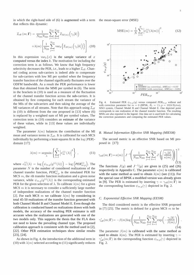
In this expressionvarkx is the sample variance ofxcomputed versus the indexk. The motivation for including thecorrection term is as follows. We know that high frequencyselectivity decreases the PER,i.e., leads to a higherIeff . Chan-nel coding across sub-carriers is indeed able to compensatefor sub-carriers with low MI per symbol when the frequencytransfer function of the channel significantly fluctuates over theODFM bandwidth. As a result the PER performance is lowerthan that obtained from the MMI per symbolin (6). The termin the brackets in (10) is used as a measure of the fluctuationof the channel transfer function across thesub-carriers. It isobtained by first computing for each stream the variance ofthe MIs of the subcarriers and then taking the average of theMI variances of all streams. Note that this approach usingIeffin (10) is different from the one proposed in [13] where (6)is replaced by a weighted sum of MI per symbol values. Thecorrection term in (10) considers anestimate of thevarianceof these values, while in [13] these values are individuallyweighted.
The parameterλ(m) balances the contribution of the MImean and variance terms inIeff . It is calibrated for each MCSindividually by performing a least-squares fit in thelog (PER)-domain [17]:
λ(m) = argminλ
N∑
i=1
∣∣∣e(i)m (λ)∣∣∣2
, (11)
where e(i)m (λ) = log(ψm,p(q
(i)(λ)))− log
(PER(i)
m,p
). The
parameterN is the number of considered realizations of thechannel transfer function,PER(i)
m,p is the simulated PER forMCSm, theith transfer function realization and a given noisevariance, whileψm,p(q
(i)(λ)) is the corresponding estimatedPER for the given selection ofλ. To calibrateλ(m) for a givenMCSm it is necessary to consider a sufficiently large numberof independent realizations of the channel transfer function[2]. For each MCSm we calibrateλ(m) by considering intotal 45-50 realizations of the transfer function generated withboth Channel Model B and Channel Model E. Even though thecalibration is conducted based on realizations drawn with bothmodels, the accuracy of the resulting PER estimator is stillaccurate when the realizations are generated with one of thetwo models only. This supports the thesis that the FLA doesnot need to know the prevailing channel type. The proposedcalibration approach is consistent with the method used in [2],[22]. Other PER estimation techniques show similar results[23], [24].
As shown in Fig. 4, the introduction of the additional term in(10) withλ(m) selected according to (11) significantly reduces
the mean-square error (MSE)
MSE(m) =1
N
N∑
i=1
∣∣∣e(i)m (λ(m))∣∣∣2
. (12)
10−3
10−2
10−1
10010
−3
10−2
10−1
100
PERm,p
ψm
,p(q
)
IdealMMIBM (no correction), MSE(m) = 0.157MMIBM (with correction), MSE(m) = 0.051
Fig. 4. Estimated PERψm,p(q) versus computedPERm,p without andwith correction parameter form = 0 (BPSK,Rc = 1/2, p = 1024Bytes),SISO system, Channel Model B and Channel Model E. One depicted pointcorresponds to one realization of the channel transfer function. The resultingMSEs are also reported in the legend. One data set is used bothfor calculatingthe correction parameters and computing the estimated PER values.
B. Mutual Information Effective SNR Mapping (MIESM)
The second metric is an effective SNR based on MI pro-posed in [17]:
γeff(m;Γ)=κ(m)
J−1
1
NSSNSD
NSS∑
j=1
NSD∑
k=1
J
(√γj [k]
κ(m)
)2
.
(13)The functionsJ(y) and J−1(y) are given in (25) and (26)respectively in Appendix C. The parameterκ(m) is calibratedwith the same method as used to obtainλ(m) (see (11)). Forthe special case of BPSK a modified version was already givenin [9]. The PER is estimated by insertingγ = γeff(m;Γ) inthe corresponding functionψm,p(γ) depicted in Fig. 2.
C. Exponential Effective SNR Mapping (EESM)
The third considered metric is the effective SNR proposedin [7] [25]. The metric is defined for a given MCSm to be
γ′eff(m;Γ)= −β(m)log
1
NSSNSD
NSS∑
j=1
NSD∑
k=1
exp
(− γj [k]β(m)
) .
(14)The parameterβ(m) is calibrated with the same method asused to obtainλ(m). The PER is estimated by insertingγ =γ′eff(m;Γ) in the corresponding functionψm,p(γ) depicted inFig. 2.

6(c) 2010 IEEE. Personal use of this material is permitted. Permission from IEEE must be obtained for all other users, including reprinting/ republishing this material for advertisingor promotional purposes, creating new collective works forresale or redistribution to servers or lists, or reuse of anycopyrighted components of this work in other works.
D. Raw Bit-Error-Rate (RawBER)
This mapping computes a single scalar value by averagingthe uncoded bit-error rates of all sub-carriers [6] [26]:
RawBER′(m;Γ)=1
NSSNSD
NSS∑
j=1
NSD∑
k=1
RawBERj,M(m)[k] .
(15)In the right-hand expressionRawBERj,M [k] is the raw BERof the jth spatial stream andkth sub-carrier when using themodulation formatM . A function ψm,p(RawBER) is usedas an estimate of the PER. Let us for example consider themodulation formatM = BPSK. If we assume that the outputof the MMSE receiver can be approximated as the output ofan AWGN channel [18], we have
RawBERj,BPSK[k] ≈ Q(√
2 γj[k]
). (16)
Notice that this metric is independent of the used code. Weintroduce a correction similar to that applied to EESM (see(14)) for RawBER:
RawBER(m;Γ) =
1
NSSNSD
NSS∑
j=1
NSD∑
k=1
Q
(√2 γj[k]
α(m)
)
√α(m)
.
(17)The parameterα(m) is calibrated with the same methodas used to obtainλ(m). The method can be generalizedto arbitrary subcarrier modulation formats.Simulations showthat with this correction, the accuracy of the PER estimationincreases.
V. ACCURACY OF THEPER ESTIMATES
In this section, we discuss the PER estimation accuracyof the four considered LQMs. The accuracy of the approx-imation in (5) can be assessed numerically by Monte Carlosimulations. To this end, estimates of the left-hand term(PERm,p(Γ)
)and the right-hand term
(ψm,p (q(m; Γ))
)in
(5) for a particular LQMq are computed for various real-izations of the channel transfer function. The steepness ofthe functionPERAWGN
m,p (q) requires the calculated LQMs tobe quite accurate. An inaccuracy of1 dB can lead to a PERestimate shifted1.5 decades away from the true PER. Fig.5 shows a scatter plot of pairs of computed and estimatedPERs using the considered LQMs for different realizationsof the channel transfer function generated with the ChannelModel B and Channel Model E.Table II reports the correctionparameters for these LQMs. The values are given in dB with(·)dB = 20 log10(·).
It can be seen that the MMIBM, MIESM and EESMmetrics provide nearly the same PER estimation accuracy, withMMIBM slightly outperforming the other two metrics. TheRawBER metric shows the largest MSE. We observe outlierswhich result when the interleaving depth of the interleaverismismatched to the current channel state. Indeed, a static inter-leaver, as used in IEEE 802.11n [14], is designed according toaverage channel statistics,i.e., the coherence bandwidth andcoherence time. However, individual realizations of the chan-nel transfer function may exhibit an instantaneous coherence
bandwidth and/or coherence time exceeding the interleaverdepth. In this case all soft bits at the interleaver output willbe affected by similar highly correlated channel weights [27].This, motivates the use of adaptive interleavers [28]. Evenwiththe presence of the outliers, the scatter plots in Fig. 5 showthatthe correction parameters are valid for both Channel ModelB and Channel Model E.We observed that each correctionparameter is robust,i.e., a small variation of it results in asmall variation of the PER estimates.
10−3
10−2
10−1
10010
−3
10−2
10−1
100
PERm,p
ψm
,p(q
)
IdealMMIBM, average MSE =0.030
MIESM, average MSE =0.031
EESM, average MSE =0.034
RawBER, average MSE =0.082
(a)m ∈ 3, 11
10−3
10−2
10−1
10010
−3
10−2
10−1
100
PERm,p
ψm
,p(q
)
IdealMMIBM, average MSE =0.073
MIESM, average MSE =0.079
EESM, average MSE =0.081
RawBER, average MSE =0.081
(b) m ∈ 7, 15Fig. 5. Scatter plots of estimated PERψm,p(q) versus computedPERm,p
for MCSs with same modulation and coding per streamm ∈ 3, 11 (a)andm ∈ 7, 15 (b). The data points are joined from both MCSs. The dataare obtained for realizations of the channel transfer functions generated withChannel Model B (2×2 MIMO) and Channel Model E (SISO) using a packetlength p = 1024Bytes. The respective correction parameters of the LQMsare computed from these scatter plots. The average MSEs are also reportedin the legends, ex:1
2(MSE(3) + MSE(11)). One data set is used both for
finding the correction parameters and computing the estimated PER values.
VI. M APPING OF THEESTIMATED PER VERSUSPACKET
LENGTH
The functionψm,p(q) is parameterized by the MCS indexm and packet lengthp. It should therefore be computed foreach pair(m, p), m ∈ Ω andp ranging in the set of supportedpacket lengths. However, in order to keep the complexity ofthe mapping low, it is desirable to storeψm,p(q) for a few ofthe most used packet length values only and to interpolate the

7
TABLE IICORRECTION PARAMETERSOF THE LQMS COMPUTEDCHANNEL MODEL B AND CHANNEL MODEL E. ALL VALUES ARE IN dB.
MCS Index 0 (8) 1 (9) 2 (10) 3 (11) 4 (12) 5 (13) 6 (14) 7 (15)
α(m) 2.61 2.70 2.66 1.22 1.74 0.99 1.22 1.42β(m) 0.13 3.15 3.12 8.52 9.45 14.68 15.34 15.70κ(m) 7.80 4.77 5.08 -0.60 -1.28 -6.62 -7.19 -7.51λ(m) -3.89 -4.15 -2.64 -5.97 -4.23 -5.21 -3.79 -2.48
PER for other packet length values from this set of referencefunctions. The simple case, which we consider here, is whenthe set contains one elementψm,pref
(q) only. We propose thefollowing interpolation:
ψm,p(q) = 1−(1− ψm,pref
(q)) p
pref . (18)
The right-hand expression yields a reasonable approximationacross a wide range ofp. This approximation has, however,a limitation: ψm,p(q) = 1 for all p when ψm,pref
(q) = 1.If a higher accuracy is needed, multiple reference curvescan be used.Since the set of packet lengths supported in apractical network is small, storing multiple reference curvesis a minor practical problem.The approach presented in [29]is an attractive alternative for turbo-codes.
VII. MCS SEARCH
The selected MCS fed back to the Tx is the MCS keepingthe PER below a given threshold,PERth. This selectionprocedure leads to a discrete optimization problem that canbe formulated as
maxm∈Ω
TP(m)
s.t. ψm,p(q(m;Γ)) ≤PERth , ∀m∈Ω∖
argminm∈Ω
TP(m)
(19)for the prevailingSINR matrixΓ. In (19), PERth is selectedsuch thatPERtarget is met on average over time. This step in-cludes some heuristics and is based on experimental evidence.The parameterPERtarget essentially controls the delay/jitter ofthe link, if retransmission is needed, and of course the through-put. Different PERtarget can therefore be used according tothe quality of service needed for the considered applications(digital video streaming, voice over IP, web-browsing, etc.).
Note that at sufficiently high and low SNR regimes itis not possible to obtain a PER close toPERtarget. Thisis because transmission with all MCSs will almost alwayssucceed at sufficiently high SNR, while it will almost alwaysfail at sufficiently low SNR. If at an given mid SNR regimePERth is selected such thatPERtarget is fulfilled on average,this PER might not be reached within a small time window.The following algorithm controlsPERth such that the FLAalgorithm approximately delivers a givenPERtarget within acertain time window: If the recorded PER is too high or toolow as time elapses in the window, then adjustPERth suchthat PER is approximately equal toPERtarget at the end ofthe window.
It is desired that the Rx always feeds back an MCS index tothe Tx. Excluding the MCS with the lowest throughput in theconstraints of the optimization problem (19) guarantees that
this problem always has a solution.If no MCS succeeds in pro-viding a sufficiently small PER, a situation that occurs at suffi-ciently low SNR, the Rx feeds backm = argminm∈Ω TP(m)to the Tx.
In the literature either the objective functionTP(m) in (19)or (1− ψm,p(q(m;Γ)))TP(m) is used for selecting the MCSto be utilized, seee.g., [13], [30]. The two objective functionsare equivalent if
PERth< minm1,m2
1− TP(m1)
TP(m2)
(20)
where
m1,m2 ∈ Ω,m1 6=m2 such thatTP(m1) ≤ TP(m2) ,
sinceTP(m) cannot differ from(1−ψm,p(q(m;Γ)))TP(m) bymore than a factor1− PERth because of the PER constraintsin (19). Condition (20) is fulfilled in the simulation setupprovided in Section IX. Hence, the MCS selection algorithmis optimal with respect to both the objective functionTP(m)and (1− ψm,p(q(m;Γ)))TP(m) for these simulations.
One way of solving (19) is by performing an exhaustivesearch across all elements inΩ [13]. We propose a sequentialsearch, in which the MCSs are first ordered in decreasingorder of their throughput and then the PER of each MCSin the list is evaluated one by one. The first MCS thatfulfils the PER constraint in (19) is the sought solution,because it has the maximum throughputamong the MCSsatisfying the PER constraint, due to the selected ordering.Both exhaustive and sequentialsearch procedures lead to thesame solution. However, the sequential search method hasa smaller computational burden compared to the exhaustivesearch method. For instance thelatterapproach searches in thecomplete set of cardinality 16 forNT = 2 [14] when the samemodulation format is used on both spatial streams, while theformer stops earlier in general. Both methods are applicablewhen the number of candidate MCSs,i.e., the cardinality ofΩ, is fairly low. We apply the sequential search method toassess the performance of the FLA algorithms in Section IX.
In case unequal modulation formats are used in the spatialstreams, the effective MI is computed to be a weighted sumof the mutual information values calculated for the individualstreams. The weights equal the relative fractions of informa-tion bits transmitted in the streams.
The transmission mode can use beamforming or spatial-multiplexing depending on the condition-number of the chan-nel.This would, for example, implyNSS = 1 for beamformingandNSS = 2 for dual-stream transmission. In order to considerboth scenarios in the MCS search an estimate of the fullMIMO channel matrixH [k] ∈ CNR×NT must beavailableat the receiver. With this estimate, the receiver calculatesanother effective channel matrix estimateH
′
[k] = H[k]Q[k],

8(c) 2010 IEEE. Personal use of this material is permitted. Permission from IEEE must be obtained for all other users, including reprinting/ republishing this material for advertisingor promotional purposes, creating new collective works forresale or redistribution to servers or lists, or reuse of anycopyrighted components of this work in other works.
with Q[k] ∈ CNT×NSS denoting the precoding matrix. Thecorresponding post-processing SINRs, LQMs and estimatedPERs are then obtained fromH
′
[k] for all possible supportedprecoding and MCS combinations.If H[k] is not available,the channel is only known for the particular precoding mode.Hence, the performance of other combinations of precodingand MCS cannot be accurately estimated.A straightforwardapproach, which is also suggested in 802.11n [14,§20.3.13.3],is that the receiver selects an MCS based on the observedchannel matrix only. That is, the MCS selection is based ona subset of the set of MCSs supported for the fully-knownchannel. This subset is determined by the observed signaldimension and the precoding capabilities of the consideredMIMO system.
VIII. A N UPPERBOUND FOR THETHROUGHPUT OFLA S
The common way of determining an upper bound for thethroughput is to evaluate the ergodic capacity of the MIMOchannel. However, the resulting bound is weak in this par-ticular context and it cannot be achieved due to the followingreasons: (i) we use only convolutional coding; (ii) we considerpractical channel estimation; and (iii) the setΩ of candidateMCSs is not infinitely large in terms of available subcarriermodulation formats and code-rate combinations.Hence, weare interested in a practical bound on the throughput for anyLA scheme. The genie-based method [2] provides such abound. However the method has high complexity because itnecessitates to simulate the PER for all MCSs, and large setsofSNRs and realizations of the channel transfer function. Insteadwe propose an upper bound and a low complexity algorithmto compute it. A similar bound was independently presentedin [13]. We show below that it is not necessary to evaluate allcandidate MCSm ∈ Ω as done in [13]. Instead, it suffices toevaluate an ordered subset of MCSs. The proposed bound canbe seen as a further generalization of the bound in [31]. Noticethat the algorithm in [31] generates a bound for a specific LAmethod, whereas the proposed algorithm generates a boundfor any LA method.
We now describe the algorithm that computes an upperbound on the throughput for a given set of candidate MCSs.The algorithm - we coined it performance bound algorithm -is depicted in Fig. 6 for the sake of clarity.Define onΩ anordering functionh, such thatTP(h(i)) ≥ TP(h(i − 1)), i ∈1, · · · , |Ω| − 1. The bound is obtained as follows: firstgenerate a realization of the channel transfer function andthen obtain an indexi ← |Ω| − 1 with the correspondingMCSm = h(i), i.e., starting with the MCS having the largestthroughput. In our case this MCS is 64QAM withRc = 5/6.This MCS is used to send a packet across the channel with thegenerated transfer function. If the transmission fails,i.e., thepacket is received incorrectly, the algorithm updatesi← i−1(if i 6= 0) and obtain a new MCSm = h(i). Notice that thethroughput of the new MCS is equal or lower than that of theprevious MCS. The new MCS isthen used to send a packetacross a channel with the same realization of the transferfunction. These steps continue until the transmitted packet isreceived successfully ori = 0 which corresponds to the MCS
Start Channel
i← i− 1i← |Ω| − 1
Generate channeltransfer function
YES YES
NO
NO
the packet transmissionSave statistics from
If receivedsuccessful If i = 0
MCS m transmitter
MCS m receiver
m← h(i)
Fig. 6. Flow graph of the performance bound algorithm. The function hfulfils the propertyTP(h(Ω, i)) ≥ TP(h(Ω, i− 1)), i ∈ 1, · · · , |Ω| − 1.
with the lowest throughput. Information on the outcome of thelast transmission (packet error event and throughput) is thensaved for later evaluation. The algorithm then generates a newrealization of the channel transfer function and starts a newcycle.
The upper bound is practically notachievablebut it is tightenough to be of practical use as we will see in Section IX. Theboundis derived in Appendix A and its tightness investigatedin Appendix B.
IX. N UMERICAL RESULTS
For the evaluation of the FLA algorithm we utilize asimulator fully compliant with the IEEE 802.11n standard[14] and the IEEE channel models [16]. Channel estimationis performed based on the long training field provided inthe preamble of a packet [14]. The channel estimates aresmoothed before they are used in (4) for the computation ofthe post-processing SINR matrixΓ. The correction param-etersα(m), β(m), κ(m), and λ(m) are found by means ofpreliminary simulations in which realizations of the channeltransfer function are generated with both Channel Model Band Channel Model E (see Section IV-A). Table II reports theobtainedvalues of these parameters. Only Channel Model Bis used to obtain the results discussed below.The sequentialsearch approach presented in Section VII is used to determinethe MCS fed back to the transmitter.
A. Throughput and PER
Simulation results of the throughput and PER versus theSNR are shown in Fig. 7. The realizations of the channelresponse are normalized such that theirtime-averagedenergyis unity. The SNR is defined as the inverse of the noise varianceγ = 1/σ2
n. For clarity we first discuss the results when FLAis not applied:
• The reported upper bound on the throughput is obtainedusing the performance bound algorithm described inSection VIII.

9
• Each curve indicated in dashed line “fixed MCS” repre-sent the throughput or PER performance versus SNR ofone individual MCSm ∈ Ω.
• The reported “fixed MCS envelopes” are obtained for agiven SNR by selecting the performance (throughput andPER) of the MCS achieving the maximum throughputat that SNR without considering any PER constraints.The bumpiness of the curve results due to the limitednumber of candidate MCSs, since a smooth transitionin performance between the optimum MCSs for twoconsecutive SNR values is not always realized.
• The reported “PER-constraint envelopes” are obtained fora given SNR by selecting the performance (throughputand PER) of the MCS achieving the maximum throughputat each SNR, while maintaining a PER value less than1%. These curves describe the performance of a slowlink adaptation (SLA) method, which selects the MCSmaximizing the throughput for a fixed noise variance,while maintaining a certain PER. Since the set of can-didate MCSs is finite, the corresponding PER curveisalso bumpy. The SLA method does not consider theinstantaneous fading in the channel realizations and henceit is less effective than FLA, as we will see shortly.
The FLA algorithms under consideration operate as follows.Within each cycle a single data packet is sent with the MCSsuggested by the receiver.The MCS feedback link is assumedto be free of error. The results are reported in Fig. 7.Thethroughput and PER values at each considered SNR value havebeen obtained by transmitting packets until 200 of them fail,with a maximum number of transmitted packets set to 3000.
It is observed that the throughput curves of the FLAalgorithms using MMIBM, MIESM, EESM and RawBER arepractically lying on top of each other, with a small degradationfor EESM around25 dB SNR. Using EESM and RawBERalso yields a slightly larger PER than with MMIBM andMIESM. The throughput performance curves of MMIBM- andMIESM-based FLA methods are at most1.7 dB shifted to theright of the throughput upper bound. Moreover, at a giventhroughput the SNR requirement for these FLA methods are9.5 dB lower than for the PER-constraint envelope.The PERstabilizes around 1% within the SNR range15− 30 dB. Thisfeature, common to all four FLA methods investigated, isknown as the inherently anti-fluctuating property of FLA [32].
All curves generated with the FLA algorithms approach thecorresponding throughput value for the fixed MCSsh(0) andh(|Ω|−1) at respectively low and high SNR regimes. An FLAalgorithm is expected to have this behaviour. For sufficientlylow SNR only MCSh(0) may lead to error-free reception;at sufficiently high SNR, all MCS lead to successful packetreception, such that the FLA algorithm selects MCSh(|Ω|−1)to ensure the highest throughput.
If the channel is time-invariant, FLA is equivalent to SLA.This means that no gain is observed by using FLA comparedto SLA in this case. On the other hand, if the channel has smalltime coherence,i.e., the channel response changes fast, SLAwill be ineffective due to the long averaging time. Generally,the smaller the time coherence, the higher the performancegain of FLA compared to SLA.
0 5 10 15 20 25 30 35 40 450
20
40
60
80
100
120
140
9.5 dB
23 24 25 26
70
72
74
76
78
1.7 dB
SNR (dB)
TP(M
bps)
0 5 10 15 20 25 30 35 40 4510
−3
10−2
10−1
100
Performance boundsFixed MCSFixed MCS envelopePER constraint envelopeFLA: MMIBMFLA: MIESMFLA: EESMFLA: RawBER
SNR (dB)
PE
R
Fig. 7. Throughput (TP) and PER versus SNR of the considered schemesusing the following settings: Channel Model B with bandwidth 20MHz,velocity of 1.2km/h, 2 × 2 MIMO OFDM system,p = 1024Bytes andPERtarget = 1% with PERth = 3% in (19).
B. MCS Feedback Delay
The performance of FLA is evaluated with respect totheMFB delay. The MFB delay is the time required for the MCSselected in the FLA algorithm to be effectively utilized at thetransmitter. We consider only the MIESM-based FLA methodto assess the impact of the MFB delay. The results for the otherconsidered FLA methods are very similar as already observedin Fig. 7. Fig. 8 shows the throughput and PER versus theMFB delay. The throughputdecreasesand the PER increasesas the MFB delay increases for both considered SNR levelsof 20 dB and30 dB. At 4.5 − 5.5ms MFB delay the loss inthroughput is only minor but we observe a drastic degradationof the PER.
We also investigate the impact of scatter velocity on FLA.The results are shown in Fig. 9. Here we select a slightlylargerPERth = 5%. We further observe that for higher scattervelocity the observed PER increases faster as a function of theMFB delay.
In general, it is hard to know the MFB delay - in IEEE802.11n it is unconstrained - or even the scatter velocity inadvance. Both factors significantly impact the observed PERas shown in Fig. 8 and Fig. 9. To address this problem, thePERtarget can be maintained by adjustingPERth based onlong-term PER statistics, without affecting the fast adaptationfeature of FLA.

10(c) 2010 IEEE. Personal use of this material is permitted. Permission from IEEE must be obtained for all other users, including reprinting/ republishing this material for advertisingor promotional purposes, creating new collective works forresale or redistribution to servers or lists, or reuse of anycopyrighted components of this work in other works.
2 2.5 3 3.5 4 4.5 5 5.5 6 7 8 9 10 15 20 40 30
40
50
60
70
80
90
100
SNR = 20 dBSNR = 30 dB
TP(M
bps)
MFB delay (ms)
2 2.5 3 3.5 4 4.5 5 5.5 6 7 8 9 10 15 20 40 10
−3
10−2
10−1
100
SNR = 20 dBSNR = 30 dB
MFB delay (ms)
PE
R
Fig. 8. Throughput (TP) and PER versus MFB delay of MIESM-based FLAwith different scatter velocity using the following settings: Channel ModelB with bandwidth 20MHz, velocity of 1.2 km/h, 2 × 2 MIMO system,p = 1024Bytes. The target PER of1% is fulfilled up to an MFB delay ofaround2.3ms. Note that the horizontal axes are non-linear.
X. CONCLUSION
We have investigated four link quality metrics (LQMs),i.e., the mean mutual information per coded bit mapping(MMIBM), the mutual information effective SNR mapping(MIESM), the effective SNR mapping (EESM) and the rawbit-error-rate (RawBER) for the purpose of fast link adaptation(FLA) in a multiple-input, multiple-output (MIMO) orthogonalfrequency division multiplexing (OFDM) system operating infrequency selective channels. Our findings, exemplified fortheIEEE 802.11n standard, indicate that introducing a correctionparameter for MMIBM considerably improves the accuracyof the packet error rate (PER) estimation. The correctionparameter depends on the modulation and coding scheme(MCS); but it is valid for a wide class of channel models.The PER estimators based on the modified MMIBM, MIESM,EESM and RawBER perform very closely. Furthermore, weproposed a practical algorithm to obtain an upper bound onthe throughput of a link adaptation method using a given setof MCSs bymeans ofsimulations. The throughput that resultsfrom using the FLA algorithms is only 1.7 dB away from thethroughput upper bound and showsa gain of up to 9.5 dBover a slow link adaptation (SLA) approach. FLA methodsusing MI metrics slightly outperform methods employingRawBER and EESM in terms of PER. FLA outperforms SLAin channels with low time coherence. The dependency on
0 0.5 1 1.5 2 2.5 3 3.5 4 4.5 5 5.5 6 7 8 9 10 14
16
18
20
22
24
TP(M
bps)
MFB delay (ms)
0 0.5 1 1.5 2 2.5 3 3.5 4 4.5 5 5.5 6 7 8 9 10 10
−2
10−1
100
1.2 km/h2.0 km/h3.0 km/h4.0 km/h
MFB delay (ms)
PE
R
Fig. 9. Throughput (TP) and PER versus MFB delay of MIESM-based FLAwith the velocity as parameter. Channel Model B with bandwidth 20MHz,1 × 1 MIMO system,SNR = 20dB, p = 1024Bytes and PERth = 5%.Note that the horizontal axes are non-linear.
feedback delay was also investigated. We observed that thePER increases rapidly to an unacceptable levelasthe feedbackdelayincreases. This effect maybe counteracted by adjustingthe PER threshold using an outer loop.
ACKNOWLEDGMENT
The authors would like to thank Dr. Karim Maouche fromWipro-NewLogic Technologies for kindly providing some ofthe simulation results.
APPENDIX
A. Derivation of the Upper Bound for the Throughput of AnyLA
We show that the algorithm proposed in Section VIII yieldsan upper bound on the throughput. Letm = fLA(H, γ,Ω) ∈ Ωbe the selection function ofany LA algorithm for the channelH = [H [k]]k=1,...,NSD
and average SNRγ. The throughputof an LA algorithm can be written as
TPLA(γ,Ω) = E
TP(m)(1− PER(m,H, γ))
, (21)
where TP(m) and PER(m,H, γ) are respectively the max-imum throughput and the PER of MCSm for the chan-nel realizationH and average SNRγ. Expectation is withrespect toH. The function TPLA depends onΩ through

11
m = fLA(H, γ,Ω). The throughput resulting from using theperformance bound algorithm is
TPPBA(γ,Ω) = E
∑
m∈Ω
TP(m)Ps(m,Ω,H, γ)
(22)
with Ps(m,Ω,H, γ) denoting the probability that MCSmis selected by the algorithm from the setΩ for the channelrealizationH andγ. AlthoughH is fixed, thermal noise caststhe outcome of successful decoding as a probabilistic process.Consider now the partitionΩ = Ωhigh ∪ m ∪ Ωlow. Theset of MCSs with throughput higher thanTP(m) is Ωhigh
and the set of MCSs with throughput lower than or equalto TP(m) is Ωlow. The evaluation of the algorithm on the setΩ = m ∪ Ωlow is
TPPBA(γ,Ω) ≥ TPPBA(γ, Ω) =
E
TP(m)Ps(m, Ω,H, γ)
+
E
∑
m∈Ωlow
TP(m)Ps(m, Ω,H, γ). (23)
Because the first evaluated MCS in the algorithm using thesetΩ is m, Ps(m, Ω,H, γ) = (1−PER(m,H, γ)). Hencethefirst term in (23) is the throughput of any LA algorithm asgiven in (21). Now,
TPPBA(γ,Ω) ≥ TPPBA(γ, Ω) ≥ TPLA(γ,Ω) (24)
holds, becauseTP(m)Ps(m,Ω,H, γ) ≥ 0. ThusTPPBA is anupper bound of throughput forany LA algorithm.
B. Discussion of the Tightness of the Upper Bound on theThroughput
Equality in (24) holds if Ps(m,Ω,H, γ) = 1 andPs(m,Ω,H, γ) = 0, ∀m ∈ Ωhigh ∪ Ωlow. In this casetheupper bound on the throughput can be achieved by an LAalgorithm. If PER ∈ 0, 1, then one MCSm will be selectedwith probability Ps(m,Ω,H, γ) = 1 by the performancebound algorithm. This corresponds to a sharp transition fromPER(m,H, γ) = 1 to PER(m,H, γ + ǫ) = 0 with ǫ > 0 inthe PER-vs-SNR plot forall MCSs.
However, the PER is a smooth decreasing function of theSNR, which implies that, in general,more than one MCSm fulfill Ps(m,Ω,H, γ) > 0 for a given H and γ. Thisgives contributions from the MCSs with larger and smallerthroughputs relative to MCSm, and hence the upper boundis not reachable byany LA algorithm. So, the setup withthe steepest PER-vs-SNR curve yields the tightest bound. Weobserve the following behaviours:
(i) For stronger codes, the PER curves drop faster versusSNR, leading to a tighter upper bound.
(ii) If only few MCSs exist with a high probability to beselected by the performance bound algorithm,i.e., withhigh Ps(m,Ω,H, γ), then the bound will be tight. So,the more MCSs to choose from, the less tight the boundis. This can be concluded from the fact that the bound isreached at very low or high SNR where only one MCSis likely to be selected (see Fig. 7).
C. Approximations of the function J(·) in (7)
In [33], the functionJ(·) in (7) is approximated by
J(x)≈a1x
3+b1x2+c1x, 0 < x < 1.6363
1− exp(a2x3+b2x
2+c2x+d2), 1.6363 ≤ x<∞(25)
with the coefficients found for the MaxLog-demapper [20]
a1 = −0.04210610 b1 = 0.209252 c1 = −0.00640081a2 = 0.00181491 b2 = −0.142675 c2 = −0.08220540d2 = 0.0549608.
From (25) we obtain the inverse function ofJ(x)
J−1(y) ≈a5y
2 + b5y + c5√y, 0 < y < 0.3646
a6 log (b6(y − 1)) + c6y, 0.3646 ≤ y ≤ 1(26)
with coefficients
a5 = 1.09542 b5 = 0.214217 c5 = 2.33727a6 = −0.706692 b6 = −0.386013 c6 = 1.75017 .
REFERENCES
[1] J. Cavers, “Variable-rate transmission for Rayleigh fading channels,”IEEE Trans. Commun., vol. 20, pp. 15–22, Feb. 1972.
[2] S. Simoens, S. Rouquette-Leveil, P. Sartori, Y. Blankenship, and B. Clas-son, “Error prediction for adaptive modulation and coding in multiple-antenna OFDM systems,”EURASIP Sig. Proc. J., Special Section:Advances in Signal Processing-assisted Cross-layer Designs, vol. 86,no. 8, pp. 1911–1919, Aug. 2006.
[3] S. Hamalainen, P. Slanina, M. Hartmann, A. Lappetel¨ainen, andH. Holma, “A novel interface between link and system level simulation,”in Proc. ACTS Mobile Summit, Aalborg, Denmark, Oct. 1997, pp. 599–604.
[4] Member of IST-WINNER Consortium, “IST-2003-507581 WINNER,Deliverable 2.7, version 1.1, Assessment of Advanced Beamforming andMIMO Technologies,” IST-WINNER, Tech. Rep., Feb. 2005.
[5] L. Berger, “Performance of Multi-Antenna Enhanced HSDPA,” Ph.D.dissertation, Aalborg Universitet, Aalborg, Denmark, Jun. 2005.
[6] M. Lamarca and F. Rey, “Indicators for PER prediction in wirelesssystems: A comparative study,” inProc. IEEE Veh. Techn. Conf. (VTC),vol. 2, no. 30, Stockholm, Sweden, May 2005, pp. 792–796.
[7] 3GPP TSG-RAN WG1, “System-level Evaluation of OFDM - FurtherConsiderations,”R1-031303, Nov. 2003.
[8] K. Sayana, J. Zhuang, and K. Stewart, “Link performance abstractionbased on mean mutual information per bit (MMIB) of the LLR channel,”IEEE 802.16 BWA WG, C802.16m-07/097, 2007.
[9] S. Shawn Tsai and Anthony C. K. Soong, “Effective-SNR Mappingfor Modelling Frame Error Rates in Multiple-State Channels, C30-20030429-010,” 3GPP2 - Ericsson, Tech. Rep., Apr. 2003, availableat ftp://ftp.3gpp2.org/TSGC/Working/2003/2003-05-SanDiego/TSG-C-2003-05-San%20Diego/WG3/WG3%20Call,%202003.04.29/.
[10] M. Lampe, T. Giebel, H. Rohling, and W. Zirwas, “PER-prediction forPHY mode selection in OFDM communication systems,” inProc. IEEEGlobal Telecomm. Conf. (GLOBECOM), San Francisco, CA, USA, Dec.2003, pp. 25 – 29.
[11] T. L. Jensen, S. Kant, J. Wehinger, and B. Fleury, “Mutual informationmetrics for fast link adaptation in IEEE 802.11n,” inProc. IEEE Int.Conf. on Comm. (ICC), Beijing, China, May 2008, pp. 4910–4915.
[12] P. H. Tan, Y. Wu, and S. Sun, “Link adaptation based on adaptivemodulation and coding for multiple-antenna OFDM system,”IEEE J.Select. Areas Commun., vol. 26, no. 8, pp. 1599–1606, Oct. 2008.
[13] Y.-S. Choi and S. M. Alamouti, “A pragmatic PHY abstraction techniquefor link adaption and MIMO switching,”IEEE J. Select. Areas Commun.,vol. 26, no. 6, pp. 960–971, Aug. 2008.
[14] IEEE Computer Society, “IEEE Standard 802.11n, Amendment 5:Enhancements for Higher Throughput,” 2009.
[15] A. Paulraj, R. Nabar, and D. Gore,Introduction to Space-Time WirelessCommunications. Cambridge University Press, 2003.
[16] Members of IEEE 802.11 TGn, “TGn Channel Models for IEEE802.11WLANs,” 802.11-03/940r4, May 2004.

12(c) 2010 IEEE. Personal use of this material is permitted. Permission from IEEE must be obtained for all other users, including reprinting/ republishing this material for advertisingor promotional purposes, creating new collective works forresale or redistribution to servers or lists, or reuse of anycopyrighted components of this work in other works.
[17] K. Brueninghaus, D. Astely, T. Salzer, S. Visuri, A. Alexiou, S. Karger,and G. Seraji, “Link performance models for system level simulations ofbroadband radio access systems,” inProc. IEEE Int. Symp. on Personal,Indoor and Mob. Radio Comm. (PIMRC), Berlin, Germany, Sep. 2005,pp. 2306 – 2311.
[18] Y. Kim, J. Cioffi, and K. Holt, “Low complexity BICM-OFDMbasedMIMO receiver using successive interference cancellation,” in Proc.Wireless Tele. Symp. (WTS), Pomona, CA, USA, Apr. 2006, pp. 1–5.
[19] I. Land, P. Hoeher, and S. Gligorevic, “Computation of symbol-wisemutual information in transmission systems with LogAPP decoders andapplication to EXIT charts,” inProc. 5th Int. ITG Conf. on Source andChannel Coding (SCC), Erlangen-Nuremberg, Germany, Jan. 2004, pp.195–202.
[20] T. L. Jensen and S. Kant, “Fast Link Adaptation for IEEE 802.11n,”Master’s thesis, Aalborg University, Denmark, Aug. 2007.
[21] B. A. Bjerke, J. Ketchum, R. Walton, S. Nanda, I. Medvedev, M. Wal-lace, and S. Howard, “Packet error probability prediction for systemlevel simulations of MIMO-OFDM based 802.11n WLANs,” inProc.IEEE Int. Conf. on Comm. (ICC), San Diego, CA, USA, May 2005, pp.2538–2542.
[22] E. Westman, “Calibration and Evaluation of the Exponential EffectiveSINR Mapping (EESM) in 802.16,” Master’s thesis, KTH ElectricalEngineering Dep., Stockholm, Sweden, Jul. 2006.
[23] Beijing University of Post and Telecommunications, “ESM Beta Train-ing in 802.16e System 3.0,” WiMAX Forum, AATG Report, 2007, Tech.Rep., 2007.
[24] Nortel Networks, “Modelling of Performance with Coloured InterferenceUsing the EESM (Exponential Effective SIR Mapping),” 3GPP TSGRAN WG1 37, R1-040509, Tech. Rep., 2004.
[25] S. Nanda and K. Rege, “Frame error rates for convolutional codes onfading channels and concept of effectiveEb/N0,” IEEE Trans. Veh.Technol., vol. 47, no. 4, pp. 1245–1250, Nov. 1998.
[26] F. Peng, J. Zhang, and W. Ryan, “Adaptive modulation andcoding forIEEE 802.11n,” inProc. IEEE Wireless Comm. and Networking Conf.(WCNC), Hong Kong, China, Mar. 11-15, 2007, pp. 656 – 661.
[27] C. Stierstorfer and R. F. H. Fischer, “Adaptive interleaving for bit-interleaved coded modulation,” inProc. 7th Int. ITG Conf. on Sourceand Channel Coding (SCC), Ulm, Germany, Jan. 2008.
[28] S. Lei and V. Lau, “Adaptive interleaving for OFDM in TDDsystems,”IEE Proc. of Commun., vol. 148, pp. 77–80, Apr. 2001.
[29] S. Dolinar, D. Divsalar, and F. Pollara, “Code performance as a functionof block size,” TMO Progress Report 42-133, Tech. Rep., May 1998.
[30] R. C. Daniels, C. M. Caramanis, and R. W. Heath, “Adaption inconvolutionally-coded MIMO-OFDM wireless systems through super-vised learning and SNR ordering,”IEEE Trans. Veh. Technol., vol. 59,no. 1, pp. 114–126, Jan. 2010.
[31] K. Freudenthaler, A. Springer, and J. Wehinger, “NovelSINR-to-CQImapping maximizing the throughput in HSDPA,” inProc. IEEE WirelessComm. and Networking Conf. (WCNC), Kowloon, China, 2007, pp.2231–2235.
[32] M. Lampe, H. Rohling, and W. Zirwas, “Misunderstandings about linkadaptation for frequency selective fading channels,” inProc. IEEE Int.Symp. on Personal, Indoor and Mob. Radio Comm. (PIMRC), Lisbon,Portugal, Sep. 2002, pp. 710–714.
[33] S. ten Brink, G. Kramer, and A. Ashikhmin, “Design of low-densityparity-check codes for modulation and detection,”IEEE Trans. Com-mun., vol. 52, no. 4, pp. 670–678, Apr. 2004.
Tobias Lindstrøm Jensen received his M.Sc. inElectrical Engineering from Aalborg University in2007. In the same year,he was awarded the Com-putational Science in Imaging (CSI) Ph.D. fellow-ship from the Danish Research Council.Tobias L.Jensen is currently affiliated with the Deparment ofElectronic Systemsat Aalborg University. In 2007,he was a research associate at Wipro-NewLogicTechnologies in Sophia-Antipolis, France.In 2009he was a visiting researcher scholar at Universityof California, Los Angeles (UCLA). His current
research interests include convex optimization based modelling, estimationand inverse problems.
Shashi Kant received M.Sc.E.E degree with spe-cialisation in Signal and Information Processingin Communications from Aalborg University, Den-mark, in August 2007. He was a research associateat Wipro NewLogic-Technologies, Sophia Antipolis,France from February 2007 to August 2007. FromSeptember 2007 to July 2008, he was a researchassistant at Radio Access Technology Section,De-partment of ElectronicSystems at Aalborg Univer-sity and an external researcher at Nokia SiemensNetworks, Aalborg, Denmark. Since July 2008, he
has beenwith ST-Ericsson AT AB, LTE & 3G Modem Solutions (erstwhileEricsson mobile platforms), Lund, Sweden, on 3GPP LTE physical layeralgorithms development, simulation and performance evaluation. His interestsare in the areas of time and frequency synchronization of OFDM systems andCQI estimation.
Joachim Wehinger was born in Hohenems, Aus-tria, in 1975. He received his Dipl.-Ing. and Ph.D.degrees in electrical engineering from TechnischeUniversitat Wien, Austria, in 2001 and 2005 andan M.Sc. degree in digital communications fromChalmers Tekniska Hogskola, Goteborg, Sweden in2002, all with distinction. From 2001 to 2006 Dr.Wehinger was employed with ForschungszentrumTelekommunikation Wien (ftw.) where he was work-ing as senior researcher and project manager in thearea of multi-user receivers and smart antennas in
3G systems. During 2006-2007 Dr. Wehinger was with Wipro-NewLogicTechnologies in Sophia-Antipolis, France, where he was in charge of modemdevelopment for IEEE 802.11n and Bluetooth 2.1+EDR. Since 2008 hehas been employed as Senior Staff Engineer with Infineon Technologies inMunich, Germany, working on baseband-chip development for3G+ mobiledevices. He authored more than 30 papers in international journals andconferences and serves as reviewer for IEEE Trans. on SignalProcessing,IEEE Trans. on Wireless Communications, and EURASIP Journal on SignalProcessing. His interests are the area of low-complexity implementations, linkadaptation, iterative receivers, MIMO, and multiuser communication systems.
Bernard H. Fleury received the diploma in electri-cal engineering and mathematics in 1978 and 1990respectively, and the doctoral degree in electricalengineering in 1990 from the Swiss Federal Instituteof Technology Zurich (ETHZ), Switzerland.
Since 1997 Bernard H. Fleury has been with theDepartment of Electronic Systems, Aalborg Univer-sity, Denmark, as a Professor in CommunicationTheory. He is the Head of the Section Navigationand Communications, one of the eight labs of thisdepartment. From 2006 to 2009 he was affiliated as
a Key Researcher with FTW Forschungszentrum Telekommunikation Wien,Austria. In 1999 he was elected IEEE Senior Member. During 1978-85and 1992-96 he was a Teaching Assistant and a Senior ResearchAssociaterespectively at the Communication Technology Laboratory at ETHZ. Between1988 and 1992 he was a Research Assistant at the Statistical Seminar atETHZ.
Prof. Fleury’s general fields of interest cover numerous aspects within com-munication theory and signal processing, mainly for wireless communications.His current areas of research include stochastic modellingand estimationof the radio channel, especially for multiple-input multiple-output (MIMO)applications and in fast time-varying environments, iterative message-passingprocessing with focus on the design of efficient, feasible advanced receiverarchitectures, and localization in wireless terrestrial systems. He has authoredand co-authored more than 100 publications in these areas. Prof. Fleury hasdeveloped with his staff a high-resolution method for the estimation of radiochannel parameters that has found a wide application and hasinspired similarestimation techniques both in academia and in industry.