aapa facilities and engineering seminar - results...
TRANSCRIPT

AAPA Facilities and Engineering Seminar
Robert Tolsma PE, PPM, D.PE
Division Manager
Atkins North America
San Diego, CA
Oct 22, 2015
Realizing the Value of Port
Infrastructure Reinvestment
Through Life Cycle Cost
Analysis
-OR-
Everything is fine until it’s not!
Agenda
• Introduction of Atkins
• Project Identification
• The Process
• Inspection, Assessment, and Surveys
• Structural Testing
• Pre-Engineering
• Asset Management Integration

Atkins at a glance
• Atkins is one of the world’s foremost engineering
design consultancies. Established in 1938.
• A long-standing reputation for technical excellence in
providing clients cost-effective and carbon-conscious
solutions.
• 18,000 employees worldwide
• World’s 15th largest global design firm (ENR 2014)
• 2,700 US Employees in 80 offices

Vision
To be the world’s best infrastructure consultancy
Mission
Who we are: vision and mission
Plan
From cost and risk planning, feasibility studies and logistics, to impact assessments and stakeholder engagement activity, we plan every aspect of our clients’ projects.
Design
Atkins designs intellectual capital such as management systems and business processes. We also design physical structures such as office towers, schools, bridges and highways.
Enable
Our clients entrust us with the management of projects, people and issues – ensuring that deadlines are met, costs are controlled, and success is delivered.

Ports & Terminal Group

Ports and Terminals
Atkins Cross Practice Integration
• Program management
• Emergency response
Landside
• Planning
• Cruise facilities
• Cargo facilities
• Structures
• Rail yards
• Infrastructure
• Warehousing
• Security and Administrative Facilities
Waterside
• Physical modeling
• Dredging
• Aids to navigation
• Structures
• Off-shore
• Marina facilities
• Beach management
• Beach nourishment
• Planning
• Roadways
• Multimodal
• Structures
• Tolls
• Ecological studies
• NEPA process
• Permitting
• Hazardous waste
• FATE modeling
• Resource mapping
• Archeology
• Environmental damage assessments
• Contracting
• Construction inspection
• Long-range scheduling
PORTS and COASTAL TRANSPORTATION CONSTRUCTION SVCS
ENVIRONMENTAL
• Upstream , midstream, downstream refining and terminals
• Greenfield and brownfield development projects
• Onshore facilities (production, processing, terminal, tank farm)
• Offshore facilities (subsea)
• Front end process design and technology selection
• Multidisciplinary feasibility, concept and FEED studies
• Production operations support
PROCESS ENGINEERING
The Process
• Collect Existing Information
• Initial Visual Inspection
• Assessment, Testing and Evaluation
• Preliminary Basis of Design
• Options Analysis and Cost Estimates
• Re-evaluate the Basis of Design and Options vs Operational Requirements and Budget

Decision Drivers
• Safety
• Operational Requirements
• Cost, Budget and ROI
• Strategic Plan
• Tenant Requirements

Project Identification:
What type of project do you have?
• Repair and Rehabilitate – Hold the line
• Upgrade - Improve
• Demolish and Replace – Start over

Repair and Rehabilitate?

Upgrade?
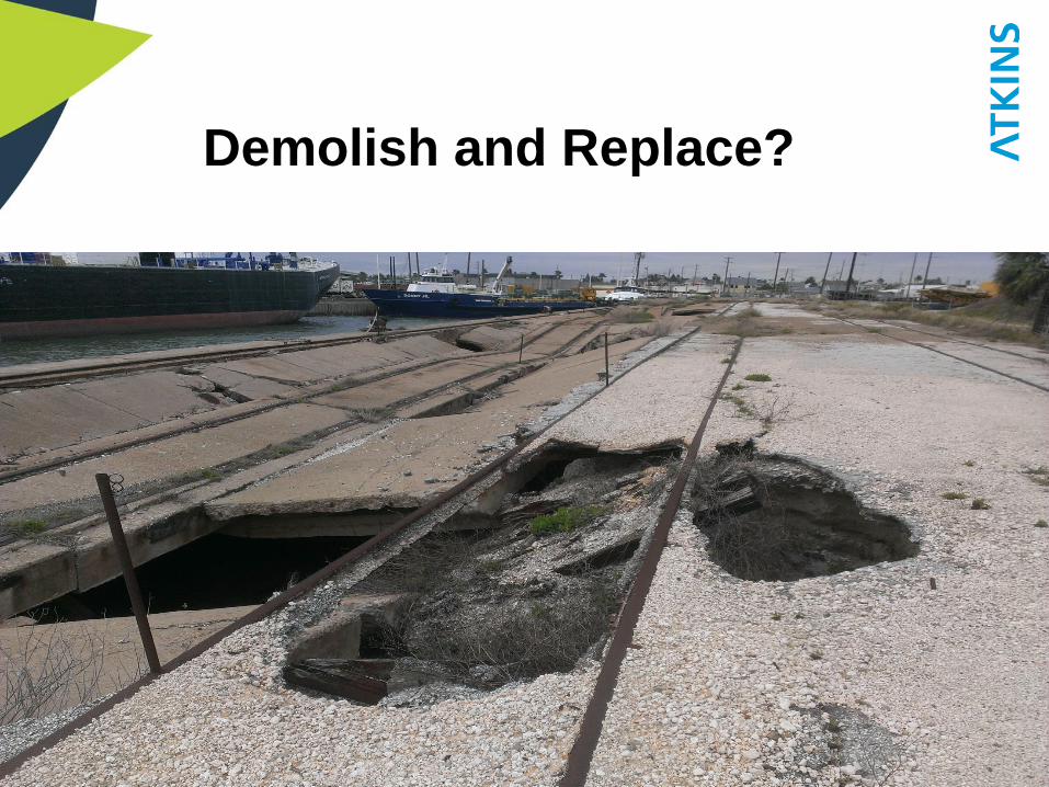
Demolish and Replace?

Assessment Phase: Surveys
1. Above and below deck Land Surveying
2. Bathymetric and Multi-Beam Survey
3. Subsurface Utility Investigation: Stormwater,
Product Lines, Electric, Communications, Etc.

Geotechnical Data Goals
• Axial capacity of existing as well as proposed piles
• Lateral capacity of piles
• Physical properties of soils: Strength, Reactivity, Etc

Geotechnical FindingsDescription
Plasticity
Index
(%)
Moisture
Content
(%)
Moisture
Content vs.
Plastic Limit1
Undrained
Shear
Strength2
(psf)
SPTN-Value3
(bpf)
Percentage
of Fines4
(%)
Silty Sand NP5 12 to 13 --- --- 2 to 4 25 to 26
Fat Clay 29 to 62 23 to 75 -1 to +53 700 to 3100 WOH6 to 16 90 to 99
Lean Clay
and Sandy
Lean Clay
8 to 29 20 to 35 +2 to +16 1100 to 2500 WOH6 to 16 69 to 100
Silt and
Sandy Silt3 26 +9 --- WOH6 to 2 ---
Clayey Sand,
Silty Sand,
and Sand
3 20 to 24 +4 --- 2 to 9 6 to 36
Elevation2
(feet)
Estimated
Unit Wt.
(pcf)
Effective
Unit
Weight3
(pcf)
Soil
Type
LPILE
Soil
Type
Number4
Lateral
Subgrade
Modulus
(pci)
Strain
(in/in)
Undrained
Shear
Strength
(psf)
Angle of
Internal
Friction
(degrees)
+12 to +5 120 -- Sand 5 25 -- 0 26
+5 to -2 115 53 Sand 5 20 -- 0 25
-2 to -26 120 58 Clay 1 -- 0.020 200 0
-26 to -36 125 63 Clay 3 -- 0.007 1000 0
-36 to -46 125 63 Clay 3 -- 0.007 1500 0
-46 to -58 125 63 Clay 3 -- 0.007 1700 0
-58 to -78 120 53 Clay 3 -- 0.007 2000 0
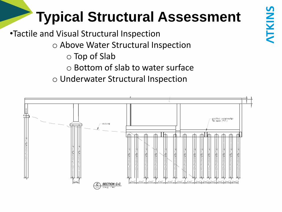
Typical Structural Assessment•Tactile and Visual Structural Inspection
o Above Water Structural Inspectiono Top of Slabo Bottom of slab to water surface
o Underwater Structural Inspection

Materials Assessment / Testing
Concrete compressive strength evaluation destructive and non-destructive coring and Schmidt hammer tests
Rebar investigation (using Ground Penetrating Radar)
Carbonation depth testing Typical structuralcross sections
cover

Topside Survey:FeaturesStructures

Below-Deck Survey:Location and geometry of existing elements

Underwater Multi-beam
Bathymetric Survey
• Similar to the above water 3D imaging, provides mudline as
well as structural/foundation elements information
• Provides information concerning piles and their location
• Combines with the above-water imaging in the 3D model
• No Surprises, nothing unexpected detected
• Useful for design including slope-stability analysis

Utility Survey

3D Model
The 3D model is similar to as-built drawings. It can
be a very effective tool in planning work due to it’s
accuracy.

Bathymetry and
multi-beam survey
3D Rendering of the Site
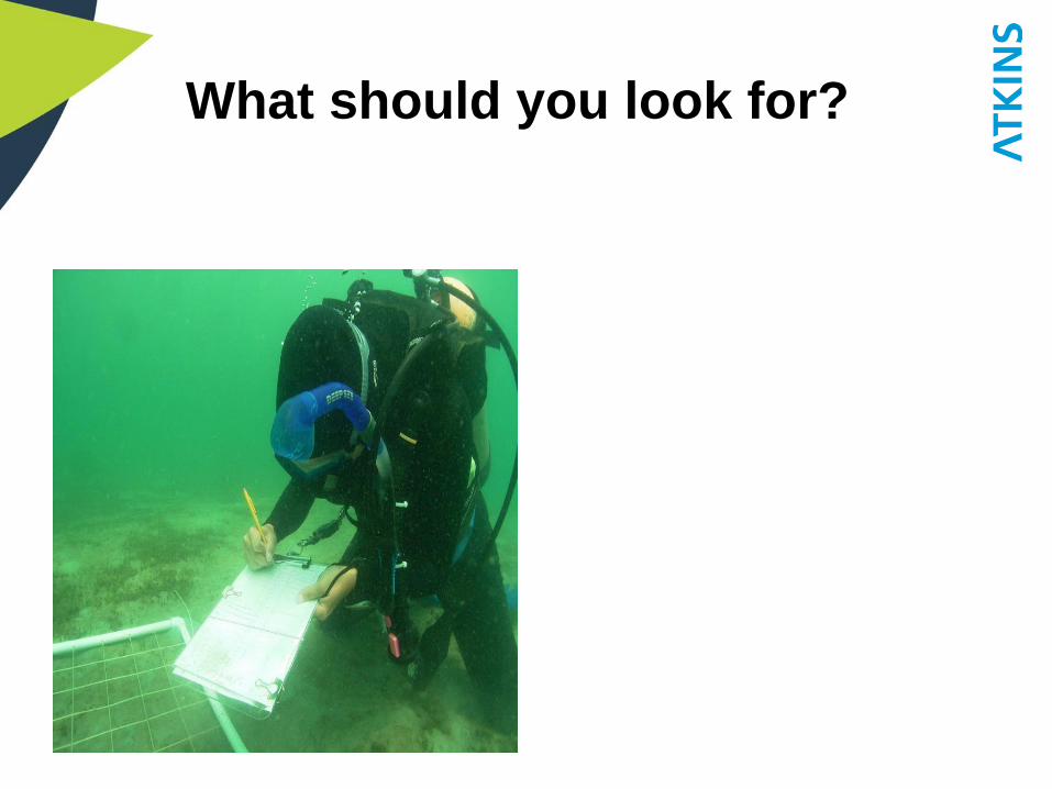
What should you look for?

ASCE Structural Inspection
Rating System
Code Description
N Not Applicable
9 Excellent Condition (Generally new construction only.)
8 Very Good Condition (No defects noted.)
7 Good Condition (Minor defects noted.)
6 Satisfactory Condition (Structural elements show some minor deterioration.)
5 Fair Condition (All primary structural elements are sound but may have minor section loss, cracking,
spalling, or scour.)
4 Poor Condition (Advanced section loss, deterioration, spalling, or scour.)
3 Serious Condition (Loss of section, deterioration, spalling, or scour have seriously affected the primary
structural components. Local failures are possible. Fatigue cracks in steel or shear cracks in concrete
may be present.)
2 Critical Condition (Advanced deterioration of primary structural elements. Fatigue cracks in steel or
shear cracks in concrete may be present or scour may have removed structural support. Unless closely
monitored, it may be necessary to close the structure until corrective action is taken.)
1 Failed Condition
FailedCriticalSeriousPoor Fair
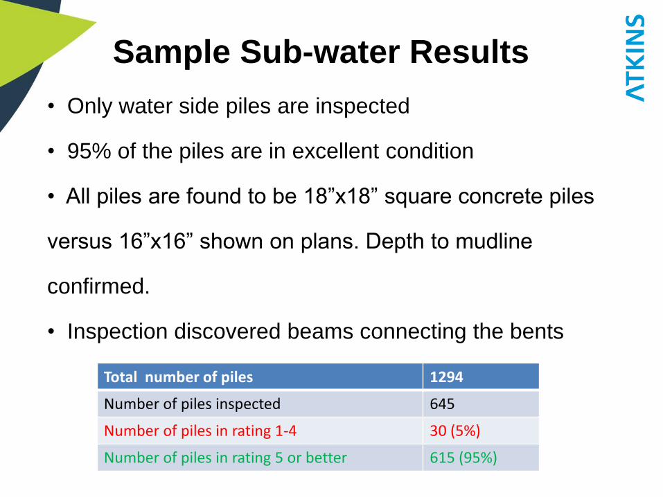
Sample Sub-water Results
• Only water side piles are inspected
• 95% of the piles are in excellent condition
• All piles are found to be 18”x18” square concrete piles
versus 16”x16” shown on plans. Depth to mudline
confirmed.
• Inspection discovered beams connecting the bents
Total number of piles 1294
Number of piles inspected 645
Number of piles in rating 1-4 30 (5%)
Number of piles in rating 5 or better 615 (95%)

Underwater Inspection
Underwater Beams

Above Water Structural
Inspection: Beams
Number of beams/Pile caps 686
Number of beams in rating 1-4 518 (~75%)
Number of Beams in rating 5-6 168 (~25%)

Above Water Structural
Inspection: Columns
Number of columns 529
Number of columns with rating 1-4 271 (51%)
Number of columns with Rating 5-6 258 (49%)

Above Water Structural
Inspection: Shear Walls
Number of shear wall segments 106
Number of shear wall segments in rating 1-4 27 (~25%)
Number of shear wall segments in rating 5-6 79 (75%)

Structural Slab Inspection
Number of slab segments 232
Number of segments in rating 1-4 232
Rating 5-6 0

GPR Scan to Locate Rebar

GPR Scan to Locate Rebar

Schmidt Hammer Test – non-
destructive test for surface
concrete

Concrete Coring: to confirm
concrete properties, perform
Carbonation Depth Test

Carbonation Depth Test

Structural Material Testing:
Durability
• If Chemical ingress depth has exceeded the
cover concrete, then there will be continued,
unabated, rebar corrosion
Typical structuralcross sections
Cover concrete

Structural Material Testing:
ConcreteNo. Structural Entity
Average
Compressive Strength
(psi)
Standard Deviation
(psi)
1 Row - 0 piles/walls 2984 246
2 Row -1 24" columns 3386 155
3 Row -1 16" columns 2902 237
4 Shear walls 3246 214
5Row 2 shear wall
columns3598 471
6 Row 2, 18" columns 3233 326
7Row 3 shear wall
columns3458 556
• Concrete compressive strength reliably above3000psi and low variability
• More than 100 rebound hammer tests show reliable concrete compressive strength throughout the structural members

Topsides Assessment: Hardware/Fenders

Establishing the Basis of Design
• Operational Requirements – Now and the foreseeable future– Cargoes to be handled and methods
– Vessel characteristics
– Barges vs ships
• Structure strength and capacity
• Single tenant or general purpose
• Design life
• Access issues
• Rail and intermodal requirements

Pre-Engineering Methodology
• Evaluate methodologies based on planned uses
• Foundations analysis in APile and LPile
• Structural sections based on current ACI design
process
• Fenders designed based on berthing energy
analysis
• Finite Element Analysis dolphin foundations
• Costs estimates based on actual quotes from
manufacturers, suppliers and local contractors

Project Example
Before After

Integrating Asset Management
into the Process

Asset Management
Optimize life-cycle costs and facilitate asset preservation
GIS technology with ESRI’s latest ArcGIS server platform

High-definition Surveying
• Terrestrial laser scanning
• 3D Models & 4D Visualization
• Digital terrain models
• Ortho-rectified imagery
• Sections, elevations & profiles
• Structural & site plans
• Surface deviation analysis
• 2 & 3 dimensional
planimetrics
• Vertical & horizontal
clearances

Marine Structural Applications
•Provides terminal operators
with a tool to better manage
assets; readily access record
drawings and facility
infrastructure information.
•Enhanced decision support
•Increased accessibility
•Improved collaboration and
consensus development
•Platform standardization

Atkins North America
Thank you!Robert Tolsma PE, PPM, D.PE
Tallahassee FL.