ab-pr quarter-turn uk/pub033...a us us a us a a us redefining flow control cast iron housing...
TRANSCRIPT

A4 US
US
A4
US
A4
A4 US
Redefining Flow Control
Cast Iron Housing Gearboxes
AB-PR Quarter-turn
AB-PR Quarter-turn Gear Series
The Rotork Gears Series ‘AB-PR’ quarter-turn gear operators are rugged, industrial grade products manufactured with cast iron housing components.
All models in this series feature a polyurethane coating and high performance axial bearings. These gear operators are well suited for applications in chemical, power, waterworks, HVAC and most general industrial applications.
Application
Rotork Gears series ‘AB-PR’ operators are quarter-turn devices intended for the operation of ball, plug and butterfly valves as well as power and process dampers.
The handwheels are available in a variety of sizes for smooth and easy operation.
Features
• Cast iron housing (ductile iron optional)
• Protected steel input shaft (stainless steel optional)
• 15 models up to 32.000 Nm (283.224 lbf.in) output
• Rugged construction
• Axial thrust bearings
• Stroke: 0 - 90° (± 5° adjustable).
Options
• Padlockable Flange
• Limit switches
• High Temperature to +200 °C
• Low Temperature to -60 °C
• Chainwheels
• Flexible Extensions
• Firesafe to ISO 10497
• Interlock Safety System
Environmental Specification
• Standard Enclosure:
N type sealed to IP67 for standard environment
• Optional Enclosure:
W type sealed to IP68 for submerged applications up to depth 1 metre for 72 hours according to EN60529:1991/14.2.8
CS type suitable for continuous submerged duty up to a maximum depth of 20 metres
G type sealed to IP68 for buried service applications
• Temperature:
-20 to +120 °C (-4 to +250 °F)

US A4
US
A4
A4US
US
A4
Redefining Flow Control
Type RatioTorque Nm (lbf.in)
M.A. ±15%
Max.Stem Height (mm)
Weight kg (lbs)Output Input
AB150 40 : 1 150 (1328) 16 (138) 9.6 48.5 /*50.5 2 (5) / *3 (7)
AB210 37 : 1 330 (2921) 28 (252) 11.6 54 4 (8) / *6 (12)
AB215 37 : 1 500 (4425) 43 (381) 11.6 54 4 (8) / *6 (12)
AB550 34 : 1 1000 (8851) 83 (738) 12 79 9 (19) / *12 (25)
AB880 38 : 1 2000 (17702) 152 (1341) 13.2 82 14 (31) / *17 (38)
AB1250 55 : 1 3250 (28765) 171 (1514) 19 91 22 (49) / *28 (61)
AB1950 52 : 1 5500 (48679) 289 (2562) 19 111 /*114 32 (71) / *45 (99)
AB2000 109 : 1 4500 (39828) 136 (1207) 33 111 24 (53) / *27 (60)
AB1950/PR4 217 : 1 7000 (61955) 106 (939) 66 111 /*114 39 (85) / *52 (115)
AB3000/PR4 243 : 1 9000 (79657) 111 (983) 81 121 /*123 49 (108) / *55.7 (123)
AB3000/PR6 348 : 1 11000 (97358) 104 (918) 106 121 /*123 51 (112) / *57 (126)
AB6800/PR4 326 : 1 12500 (110634) 130 (1152) 96 121 /*142 62.5 (138) / *92.5 (204)
AB6800/PR6 468 : 1 17000 (150463) 121 (1075) 140 121 /*142 64.2 (142) / *94.2 (208)
A200/PR10 729 : 1 26000 (230120) 124 (1096) 210 165 134.4 (296)
A250/PR10 729 : 1 32000 (283224) 142 (1259) 225 169 219.4 (484)
*Dimensions if the large base housing is used. The static safety factor is 1.5.The published M.A. is achieved after a few cycles.
TypeDimensions Maximum (Inserts)
ØM ØN O P ØQ R S
AB150 25 (0.98) 15 (0.59) 19.6 (0.77) 5 (0.2) 18.1 (0.71) 14 (0.55) 14 (0.55)
AB210 32.15 (1.27) 20 (0.79) 25.6 (1.01) 6 (0.24) 22.2 (0.87) 17 (0.67) 17 (0.67)
AB215 32.15 (1.27) 20 (0.79) 25.6 (1.01) 6 (0.24) 22.2 (0.87) 17 (0.67) 17 (0.67)
AB550 45.3 (1.78) 30 (1.18) 36.6 (1.44) 8 (0.31) 36.2 (1.43) 27 (1.06) 27 (1.06)
AB880 60 (2.36) 44 (1.73) 50.6 (1.99) 12 (0.47) 48.2 (1.90) 36 (1.42) 36 (1.42)
AB1250 60 (2.36) 44 (1.73) 50.6 (1.99) 12 (0.47) 48.2 (1.90) 36 (1.42) 36 (1.42)
AB1950 TBC TBC TBC TBC TBC TBC TBC
Inserts are not retained in the gearbox, please specify if required.
Material specification for Rotork AB-PR Quarter-turn Gear Series
No. Description Material Notes
1 Set-screw Carbon Steel DIN915 / grade 12.9
2 Worm Carbon Steel C45 / AISI1045
3 Gasket Liquid seal -
4 Axial-Bearing Hardened Steel -
5 Bushing P10, P14 PAP
6 Oil-seal Nitrile -
7 Shaft Protected Steel C45 / AISI1045 (For PR the material is 40Cr Low Alloy Steel)
8 Grease Renolit CLX2 -
9 Position indicator Scanblend FS7 PC/ASA -
10 Coverplate Cast Iron GG25 / ASTM A48-40
11 Quadrant Ductile Iron GGG40 / ASTM D60-40-18
11A Quadrant AB215 Ductile Iron GGG50 / ASTM D70-50-05
12 Body Cast Iron GG25 / ASTM A48-40
13 Gear Carbon Steel C45 / AISI1045
14 Carrier Steel EN8 / GB/T 699 GRADE 45
Note: Due to the company’s policy of continuous improvement, Rotork Gears reserves the right to change specification details without prior notice. Protected steel and stainless steel available. Ductile Iron housing available as option.
Inserts Valve Stem Variations
1
4 5 6 7 10 9
1214
11
8
13
Flat head stemKeyed stem Square stem 90º
BC
OFF
CEN
TER
A
B
DC
øM
E
H
F
K
2 3
øN
P
øQ
R
S
O
L
W
U
T
Centerpoint (4x)
V
G
J
Z
Y
Centerpoint (1x)
X
SHU
T1
4 5 6 7 10 9
1214
11
8
13
Flat head stemKeyed stem Square stem 90º
BC
OFF
CEN
TER
A
B
DC
øM
E
H
F
K
2 3
øN
P
øQ
R
S
O
L
W
U
T
Centerpoint (4x)
V
G
J
Z
Y
Centerpoint (1x)
X
SHU
T
1
4 5 6 7 10 9
1214
11
8
13
Flat head stemKeyed stem Square stem 90º
BC
OFF
CEN
TER
A
B
DC
øM
E
H
F
K
2 3
øN
P
øQ
R
S
O
L
W
U
T
Centerpoint (4x)
V
G
J
Z
Y
Centerpoint (1x)
X
SHU
T
A4 US
US
A4
US
A4
A4 US
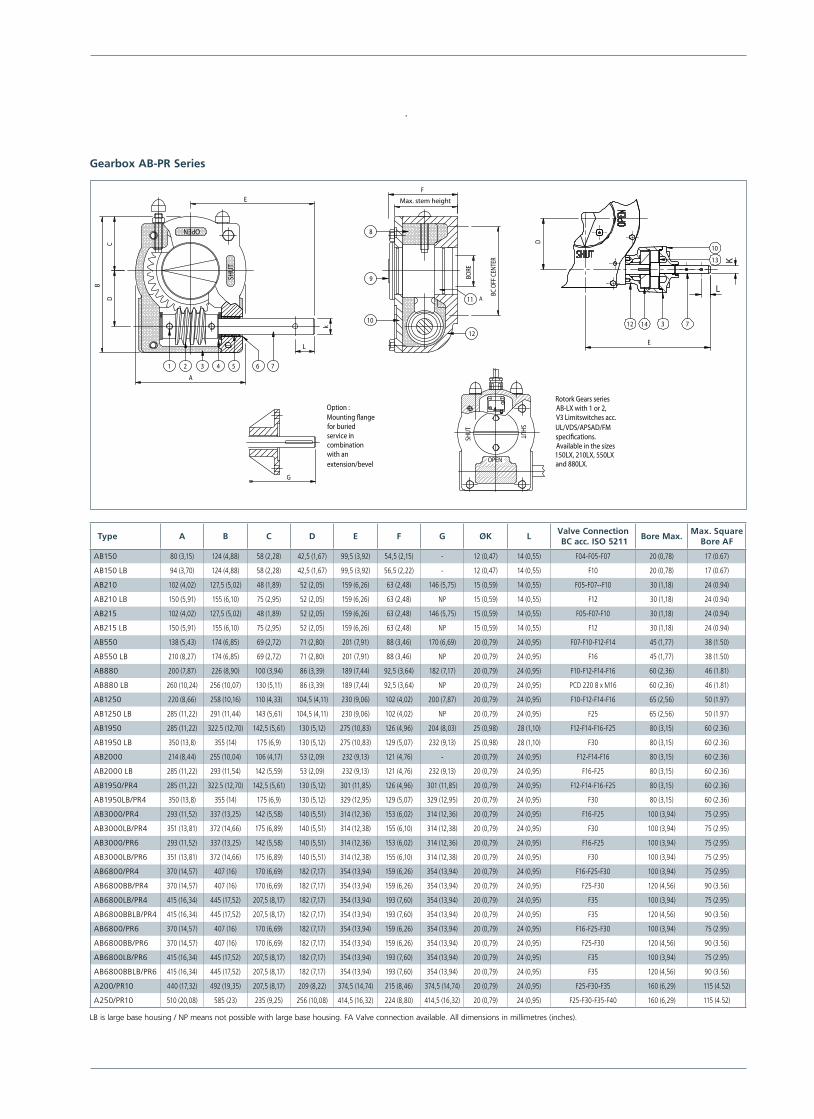
Gearbox AB-PR Series
9
8
10
12
11
F
BC O
FF C
ENTE
R
BORE
Option :
G=
Mounting �angefor buriedservice incombinationwith anextension/bevel
OPEN
SHUT
SHUT
Rotork Gears series AB-LX with 1 or 2, V3 Limitswitches acc. UL/VDS/APSAD/FM speci�cations.Available in the sizes 150LX, 210LX, 550LX and 880LX.
OPEN
SHUT
1 2 3 4 5 6 7
E
k
A
CD
B
L
Max. stem height
A
E
D
10
13
12 3 714
L
K9
8
10
12
11
F
BC O
FF C
ENTE
R
BORE
Option :
G=
Mounting �angefor buriedservice incombinationwith anextension/bevel
OPEN
SHUT
SHUT
Rotork Gears series AB-LX with 1 or 2, V3 Limitswitches acc. UL/VDS/APSAD/FM speci�cations.Available in the sizes 150LX, 210LX, 550LX and 880LX.
OPEN
SHUT
1 2 3 4 5 6 7
E
k
A
CD
B
L
Max. stem height
A
E
D
10
13
12 3 714
L
K
9
8
10
12
11
F
BC O
FF C
ENTE
R
BORE
Option :
G=
Mounting �angefor buriedservice incombinationwith anextension/bevel
OPENSH
UT
SHUT
Rotork Gears series AB-LX with 1 or 2, V3 Limitswitches acc. UL/VDS/APSAD/FM speci�cations.Available in the sizes 150LX, 210LX, 550LX and 880LX.
OPEN
SHUT
1 2 3 4 5 6 7
E
k
A
CD
B
L
Max. stem height
A
E
D
10
13
12 3 714
L
K
9
8
10
12
11
F
BC O
FF C
ENTE
R
BORE
Option :
G=
Mounting �angefor buriedservice incombinationwith anextension/bevel
OPEN
SHUT
SHUT
Rotork Gears series AB-LX with 1 or 2, V3 Limitswitches acc. UL/VDS/APSAD/FM speci�cations.Available in the sizes 150LX, 210LX, 550LX and 880LX.
OPEN
SHUT
1 2 3 4 5 6 7
E
k
A
CD
B
L
Max. stem height
A
E
D
10
13
12 3 714
L
K
Type A B C D E F G ØK LValve Connection BC acc. ISO 5211
Bore Max.Max. Square
Bore AF
AB150 80 (3,15) 124 (4,88) 58 (2,28) 42,5 (1,67) 99,5 (3,92) 54,5 (2,15) - 12 (0,47) 14 (0,55) F04-F05-F07 20 (0,78) 17 (0.67)
AB150 LB 94 (3,70) 124 (4,88) 58 (2,28) 42,5 (1,67) 99,5 (3,92) 56,5 (2,22) - 12 (0,47) 14 (0,55) F10 20 (0,78) 17 (0.67)
AB210 102 (4,02) 127,5 (5,02) 48 (1,89) 52 (2,05) 159 (6,26) 63 (2,48) 146 (5,75) 15 (0,59) 14 (0,55) F05-F07--F10 30 (1,18) 24 (0.94)
AB210 LB 150 (5,91) 155 (6,10) 75 (2,95) 52 (2,05) 159 (6,26) 63 (2,48) NP 15 (0,59) 14 (0,55) F12 30 (1,18) 24 (0.94)
AB215 102 (4,02) 127,5 (5,02) 48 (1,89) 52 (2,05) 159 (6,26) 63 (2,48) 146 (5,75) 15 (0,59) 14 (0,55) F05-F07-F10 30 (1,18) 24 (0.94)
AB215 LB 150 (5,91) 155 (6,10) 75 (2,95) 52 (2,05) 159 (6,26) 63 (2,48) NP 15 (0,59) 14 (0,55) F12 30 (1,18) 24 (0.94)
AB550 138 (5,43) 174 (6,85) 69 (2,72) 71 (2,80) 201 (7,91) 88 (3,46) 170 (6,69) 20 (0,79) 24 (0,95) F07-F10-F12-F14 45 (1,77) 38 (1.50)
AB550 LB 210 (8,27) 174 (6,85) 69 (2,72) 71 (2,80) 201 (7,91) 88 (3,46) NP 20 (0,79) 24 (0,95) F16 45 (1,77) 38 (1.50)
AB880 200 (7,87) 226 (8,90) 100 (3,94) 86 (3,39) 189 (7,44) 92,5 (3,64) 182 (7,17) 20 (0,79) 24 (0,95) F10-F12-F14-F16 60 (2,36) 46 (1.81)
AB880 LB 260 (10,24) 256 (10,07) 130 (5,11) 86 (3,39) 189 (7,44) 92,5 (3,64) NP 20 (0,79) 24 (0,95) PCD 220 8 x M16 60 (2,36) 46 (1.81)
AB1250 220 (8,66) 258 (10,16) 110 (4,33) 104,5 (4,11) 230 (9,06) 102 (4,02) 200 (7,87) 20 (0,79) 24 (0,95) F10-F12-F14-F16 65 (2,56) 50 (1.97)
AB1250 LB 285 (11,22) 291 (11,44) 143 (5,61) 104,5 (4,11) 230 (9,06) 102 (4,02) NP 20 (0,79) 24 (0,95) F25 65 (2,56) 50 (1.97)
AB1950 285 (11,22) 322.5 (12,70) 142,5 (5,61) 130 (5,12) 275 (10,83) 126 (4,96) 204 (8,03) 25 (0,98) 28 (1,10) F12-F14-F16-F25 80 (3,15) 60 (2.36)
AB1950 LB 350 (13,8) 355 (14) 175 (6,9) 130 (5,12) 275 (10,83) 129 (5,07) 232 (9,13) 25 (0,98) 28 (1,10) F30 80 (3,15) 60 (2.36)
AB2000 214 (8,44) 255 (10,04) 106 (4,17) 53 (2,09) 232 (9,13) 121 (4,76) - 20 (0,79) 24 (0,95) F12-F14-F16 80 (3,15) 60 (2.36)
AB2000 LB 285 (11,22) 293 (11,54) 142 (5,59) 53 (2,09) 232 (9,13) 121 (4,76) 232 (9,13) 20 (0,79) 24 (0,95) F16-F25 80 (3,15) 60 (2.36)
AB1950/PR4 285 (11,22) 322.5 (12,70) 142,5 (5,61) 130 (5,12) 301 (11,85) 126 (4,96) 301 (11,85) 20 (0,79) 24 (0,95) F12-F14-F16-F25 80 (3,15) 60 (2.36)
AB1950LB/PR4 350 (13,8) 355 (14) 175 (6,9) 130 (5,12) 329 (12,95) 129 (5,07) 329 (12,95) 20 (0,79) 24 (0,95) F30 80 (3,15) 60 (2.36)
AB3000/PR4 293 (11,52) 337 (13,25) 142 (5,58) 140 (5,51) 314 (12,36) 153 (6,02) 314 (12,36) 20 (0,79) 24 (0,95) F16-F25 100 (3,94) 75 (2.95)
AB3000LB/PR4 351 (13,81) 372 (14,66) 175 (6,89) 140 (5,51) 314 (12,38) 155 (6,10) 314 (12,38) 20 (0,79) 24 (0,95) F30 100 (3,94) 75 (2.95)
AB3000/PR6 293 (11,52) 337 (13,25) 142 (5,58) 140 (5,51) 314 (12,36) 153 (6,02) 314 (12,36) 20 (0,79) 24 (0,95) F16-F25 100 (3,94) 75 (2.95)
AB3000LB/PR6 351 (13,81) 372 (14,66) 175 (6,89) 140 (5,51) 314 (12,38) 155 (6,10) 314 (12,38) 20 (0,79) 24 (0,95) F30 100 (3,94) 75 (2.95)
AB6800/PR4 370 (14,57) 407 (16) 170 (6,69) 182 (7,17) 354 (13,94) 159 (6,26) 354 (13,94) 20 (0,79) 24 (0,95) F16-F25-F30 100 (3,94) 75 (2.95)
AB6800BB/PR4 370 (14,57) 407 (16) 170 (6,69) 182 (7,17) 354 (13,94) 159 (6,26) 354 (13,94) 20 (0,79) 24 (0,95) F25-F30 120 (4,56) 90 (3.56)
AB6800LB/PR4 415 (16,34) 445 (17,52) 207,5 (8,17) 182 (7,17) 354 (13,94) 193 (7,60) 354 (13,94) 20 (0,79) 24 (0,95) F35 100 (3,94) 75 (2.95)
AB6800BBLB/PR4 415 (16,34) 445 (17,52) 207,5 (8,17) 182 (7,17) 354 (13,94) 193 (7,60) 354 (13,94) 20 (0,79) 24 (0,95) F35 120 (4,56) 90 (3.56)
AB6800/PR6 370 (14,57) 407 (16) 170 (6,69) 182 (7,17) 354 (13,94) 159 (6,26) 354 (13,94) 20 (0,79) 24 (0,95) F16-F25-F30 100 (3,94) 75 (2.95)
AB6800BB/PR6 370 (14,57) 407 (16) 170 (6,69) 182 (7,17) 354 (13,94) 159 (6,26) 354 (13,94) 20 (0,79) 24 (0,95) F25-F30 120 (4,56) 90 (3.56)
AB6800LB/PR6 415 (16,34) 445 (17,52) 207,5 (8,17) 182 (7,17) 354 (13,94) 193 (7,60) 354 (13,94) 20 (0,79) 24 (0,95) F35 100 (3,94) 75 (2.95)
AB6800BBLB/PR6 415 (16,34) 445 (17,52) 207,5 (8,17) 182 (7,17) 354 (13,94) 193 (7,60) 354 (13,94) 20 (0,79) 24 (0,95) F35 120 (4,56) 90 (3.56)
A200/PR10 440 (17,32) 492 (19,35) 207,5 (8,17) 209 (8,22) 374,5 (14,74) 215 (8,46) 374,5 (14,74) 20 (0,79) 24 (0,95) F25-F30-F35 160 (6,29) 115 (4.52)
A250/PR10 510 (20,08) 585 (23) 235 (9,25) 256 (10,08) 414,5 (16,32) 224 (8,80) 414,5 (16,32) 20 (0,79) 24 (0,95) F25-F30-F35-F40 160 (6,29) 115 (4.52)
LB is large base housing / NP means not possible with large base housing. FA Valve connection available. All dimensions in millimetres (inches).
US A4
US
A4
A4US
US
A4
Redefining Flow Control
Cast Iron Housing Gearboxes
AB-PR Quarter-turn
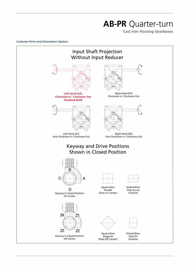
Customer Drive and Orientation Options
Keyway In Closed PositionOn Center
Keyway In Closed PositionOff Center
Square BoreParallel
(Flats on Center)
Slotted BoreFlats Across
Flowline
Slotted BoreFlats OnFlowline
Square BoreDiagonal
(Flats Off Center)
Keyway and Drive PositionsShown in Closed Position
Input Shaft ProjectionWithout Input Reducer
Right Hand (B1)Clockwise In / Clockwise Out
Left Hand (A2)Clockwise In / Clockwise Out
Standard Build
Right Hand (B2)Anti-Clockwise In / Clockwise Out
Left Hand (A1)Anti-Clockwise In / Clockwise Out

A4 US
US
A4
US
A4
A4 US
IP RATING AND SPECIFICATION FOR AB-PR SERIES GEARBOXES
Service: Standard Duty Marinised Duty Buried Service Duty Continuous Submerged Duty
Duty N W G CS
IP Rating IP67 IP68 IP68 IP68
Time & Depth 30 min to a depth of 1 metre
72 hours to a depth of 1 metre in clean water.
Buried service Continuously submerged to a depth of 20 metres.
Input Shafts C45 Carbon Steel or 40Cr Low Alloy Steel, Electrophoresis protection
Stainless Steel 303 or Stainless Steel 431
Stainless Steel 303 or Stainless Steel 431
Stainless Steel 316 or F53 Super Duplex
Fasteners Steel. Stainless Steel A4 Stainless Steel A4 Stainless Steel A4
Position Indicator FS7 (plastic) up to AB3000 and Metal for A6800 and above
Powder coated Metal with O-Ring
Metal Non-rotating plate
Non-rotating plate. If indication is required it will be in SS316
AB880 + W100 90º Bevel + extension + ECL + HW
A200N PR10
AB880 + Soldo Switchbox + Direct Mount Chainwheel
A4US
US
A4
US A4
US
A4
Formerly RGm110E. As part of a process of on-going product development, Rotork reserves the right to amend and change specifications without prior notice. Published data may be subject to change. For the very latest version release, visit our website at www.rotork.com. The name Rotork is a registered trademark. Rotork recognizes all registered trademarks. Published and produced in the UK by Rotork Controls Limited. POWTG0715
A full listing of our worldwide sales and service network is available on our website at
www.rotork.com
Rotork Gears BVNijverheidstraat 257581 PV LosserP.O. Box 98 7580 AB LosserThe Netherlands
tel +31 (0)53-5388677fax +31 (0)53-5383939email [email protected]
Rotork Gears UK 9 Brown Lane WestHolbeckLeedsWest Yorkshire LS12 6BHEngland
tel +44 (0)113 256 7922email [email protected]
Rotork Gears Americas1811 BrittmooreHoustonTexas 77043USA
tel +1 713 983 7381fax +1 713 856 8022email [email protected]
Rotork Gears S.R.L.via Olona, 65/6720015 Parabiago (MI)Italy
tel +39 0331 552128fax +39 0331 553147email [email protected]
Rotork Gears ShanghaiNo. 260 Lian Cao RoadXin Mei Urban Industrial ParkMin Hang DistrictShang Hai 201108China
tel 0086-21-33236200fax 0086-21-64348388email [email protected]
Rotork Gears India 165/166, Bommasandra, Jigani Link Road,Kiadb Industrial Area,Anekal Thaluk, Jigani Hobli,Bangalore 562106
tel +91 80 3098 1600fax +91 80 3098 1610email [email protected]
Rotork ValvekitsBrookside WayNunn ParkHuthwaiteNottinghamshire NG17 2NLEngland
tel +44 (0)1623 440211fax +44 (0)1623 440214email [email protected]
Rotork Valvekits AmericasRenfro Associates Inc 501 South 12th Street Broken Arrow, OK 74012 USA
tel +1 (918) 259-8100 fax +1 (918) 259-9167 email [email protected]
PUB033-006-00 Issue 07/15
Cast Iron Housing Gearboxes
AB-PR Quarter-turn
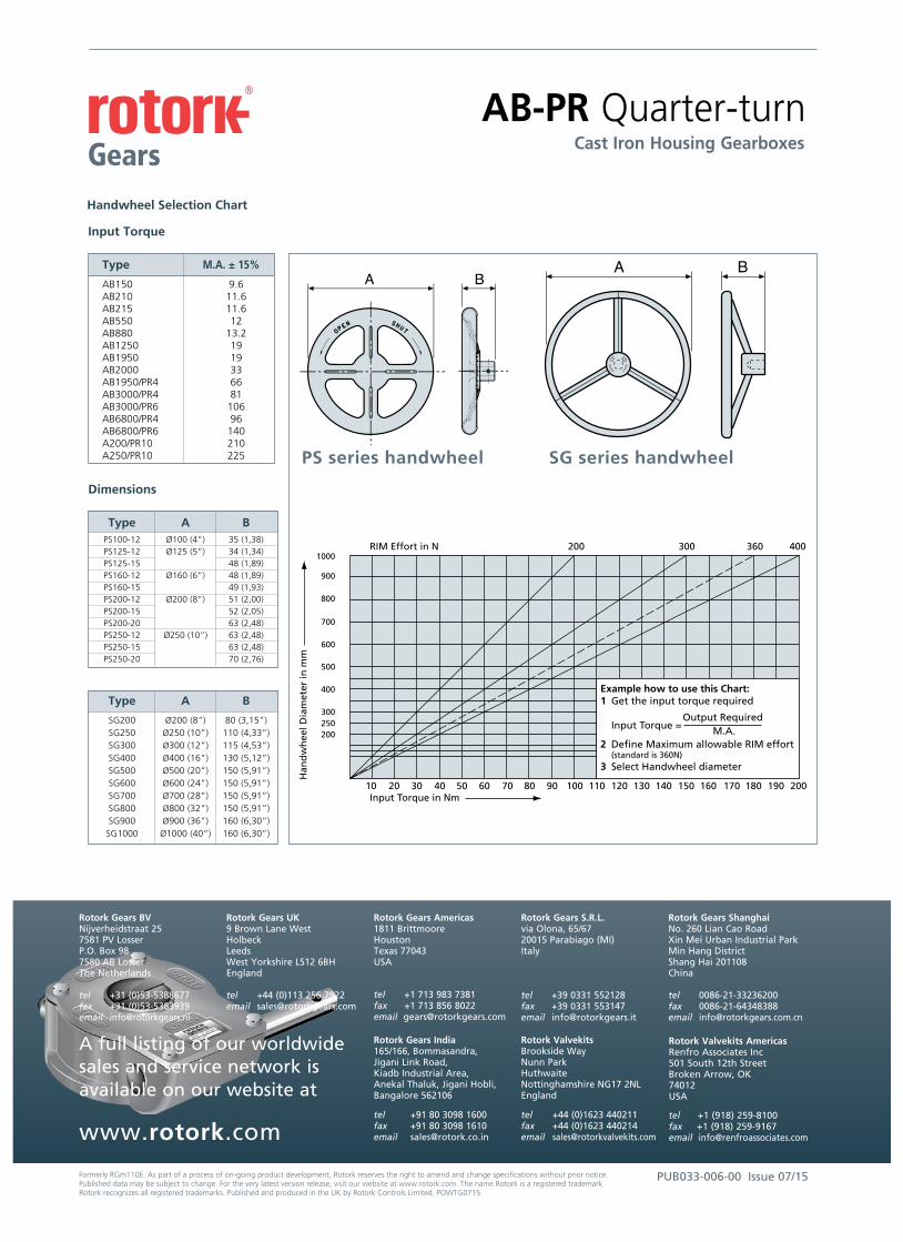
Handwheel Selection Chart
Input Torque
Type M.A. ± 15%
AB150 9.6 AB210 11.6 AB215 11.6 AB550 12 AB880 13.2 AB1250 19 AB1950 19 AB2000 33 AB1950/PR4 66 AB3000/PR4 81 AB3000/PR6 106 AB6800/PR4 96 AB6800/PR6 140 A200/PR10 210 A250/PR10 225
Dimensions
Type A B PS100-12 Ø100 (4”) 35 (1,38) PS125-12 Ø125 (5”) 34 (1,34) PS125-15 48 (1,89) PS160-12 Ø160 (6”) 48 (1,89) PS160-15 49 (1,93) PS200-12 Ø200 (8”) 51 (2,00) PS200-15 52 (2,05) PS200-20 63 (2,48) PS250-12 Ø250 (10”) 63 (2,48) PS250-15 63 (2,48) PS250-20 70 (2,76)
Type A B
SG200 Ø200 (8”) 80 (3,15”) SG250 Ø250 (10”) 110 (4,33”) SG300 Ø300 (12”) 115 (4,53”) SG400 Ø400 (16”) 130 (5,12”) SG500 Ø500 (20”) 150 (5,91”) SG600 Ø600 (24”) 150 (5,91”) SG700 Ø700 (28”) 150 (5,91”) SG800 Ø800 (32”) 150 (5,91”) SG900 Ø900 (36”) 160 (6,30”) SG1000 Ø1000 (40”) 160 (6,30”)
PS series handwheel
A B
SG series handwheel
SHUTOP
EN
A B
1000
900
800
700
600
500
400
300250200
200 300 360 400RIM Effort in N
Example how to use this Chart:1 Get the input torque required Output Required Input Torque = M.A.2 Define Maximum allowable RIM effort (standard is 360N)3 Select Handwheel diameter
Han
dw
hee
l Dia
met
er in
mm
Input Torque in Nm10 20 30 40 50 60 70 80 90 100 110 120 130 140 150 160 170 180 190 200