abb i-bus eib universal interface, 2-fold, fm us/u 2.2, gh ... · page 2 of 28 usu_22_td_en_v1-1...
TRANSCRIPT

Page 1 of 28USU_22_TD_EN_V1-12CDC 504 022 D0201
ABB i-bus® EIB
US/U 2.2US/U 2.2
44
Universal Interface, 2-fold, FMUS/U 2.2, GH Q631 0074 R0111
The device has four channels whichcan either be parameterised as inputsor outputs by selecting the application inthe ETS2 program.
Using the colour-coded connecting ca-bles, it is possible to connect conventio-nal push buttons, floating contacts orlight-emitting diodes.
The scanning voltage for the contactsand the supply voltage for the LEDs aremade available by the device.
SK
020
0 B
02
Technical Data
Power supply – EIB 24 V DC, via the bus linePower consumption < approx. 10 mA
Inputs/outputs – Number 2, can be parameterised as inputs oroutputs (depending on the application)
– Permitted cable length � 10 mInput – Scanning voltage 20 V DC
– Input current 0.5 mAOutput – Supply voltage 5 V DC
– Output current max. 2 mA, limited via 1.5 k�series resistor
– Safety short-circuit-proof, overload protection,reverse voltage protection
Operating and display elements – Red LED and push button for assigning thephysical address
Connections – Inputs/outputs 4 cables of approx. 30 cm in lengthcan be extended to max. 10 m
– EIB Bus connecting terminalincluded with supply
Type of protection – IP 20, EN 60 529when installed
Protection class – IIIAmbient temperature range – Operation - 5 °C … 45 °C
– Storage - 25 °C … 55 °C– Transport - 25 °C … 70 °C
Dimensions – 39 x 40 x 12 mm (H x W x D)Weight – 0.05 kgCertification – EIB-certifiedCE norm – in accordance with the EMC guideline
and the low voltage guideline
Series resistors for external LEDs areintegrated in the device.
The universal interface is inserted in aconventional 60 mm combined wall andjoint box.
The bus connection is carried out viathe bus connecting terminal supplied.

Page 2 of 28USU_22_TD_EN_V1-12CDC 504 022 D0201
ABB i-bus® EIB
US/U 2.2US/U 2.2
44
Universal Interface, 2-fold, FMUS/U 2.2, GH Q631 0074 R0111
Circuit diagram
1 Programming LED/push button 2 Inputs/outputs3 Bus terminal
S 0
071
Z02
Application progr ams Number of Max. number of Max. number ofcommunication objects group addresses associations
Binary Input Display Heat 2f/1 15 254 254
Note Please note that you can only pro-gram the universal interface usingETS2 from version 1.2 onwards.
The grey wire forms a common refe-rence potential for the connected pushbutton or switch contacts.
The black wire forms a common refe-rence potential for the LEDs.
Wires that are not required should beinsulated.
Further detailed information aboutthe installation, programming andapplication can be found in the “Pro-duct manual for US/U 2.2 and US/U4.2”.

Page 3 of 28USU_22_TD_EN_V1-12CDC 504 022 D0201
ABB i-bus® EIB
US/U 2.2US/U 2.2
44
Universal Interface, 2-fold, FMUS/U 2.2, GH Q631 0074 R0111
The application program makes a sepa-rate set of parameters and communica-tion objects available for each input.Further parameters or different commu-nication objects are displayed depen-ding on the parameter settings.
Bus voltage recovery
After bus voltage recovery, the interfacedoes not start to send immediately butonly once an adjustable delay has elap-sed.
The initialisation period of 2 s is alreadyincluded in the sending delay.
Limit telegram rate
On the general parameter page, it ispossible to limit the number of tele-grams that are sent over a specific timeperiod. This factor should be noted pri-marily on bus voltage recovery when alarge number of bus devices send theircurrent status simultaneously.
Function of inputs/outputs
The parameter setting “Function of thechannel” defines the operating mode ofthe input. The following functions can beselected:– switch sensor,– switch/dimming sensor,– shutter sensor,– value / forced operation,– scene control,– control of electronic relay
(heating actuator),– LED control,– switching sequence (“latching
relay”),– push button with multiple operation– or pulse counter.Alternatively, it is possible to fully deac-tivate an input with the setting “nofunction”.
Disable
It is possible to disable an input via the1 bit communication object. To do so, atelegram with the value “1” must be re-ceived. A telegram with the value “0”cancels the lock-out. The disable objectis activated for all the input functions,except for the operation of an electronicrelay and LED control.
Binary Input Display Heat 2f/1
Selection in ETS2
– ABBIn/Output
Binary/binary
�
Switch sensor
If the function of the input is set as aswitch sensor, it is possible to connectconventional push buttons to the inputsof the universal interface. The ETS2program makes at least one 1 bit com-munication object “Input ... - Telegr.switch” available for each switch sensorinput.
If the setting “Distinction between longand short operation” is set to “yes”, theswitch sensor can distinguish betweena short and a long input signal. A furtherobject “Input ... -long - Telegr. switch”can be activated via the parameter“Number of objects for short/long ope-ration” so that it only reacts to long ope-rations.
Both normally closed and normally opencontacts can be connected to the re-spective input. If normally open con-tacts are used for example, the setting“Connected contact type” must be setto “normally open”.
The information that should be sentwhen the push button is pressed is defi-ned separately for each switch object.Either an ON or OFF telegram can betriggered. Alternatively, no reaction cantake place after a push button operati-on.
It is possible to specify the period whichis interpreted as a long operation by theinput. Intervals from 200 ms upwardscan be set. The period comprises abase and a factor.
Period for long operation =Base * Factor
An adjustable debounce time can be setto prevent a bounce at the contacts ofconventional push buttons or switchesfrom having a negative influence. Thedefault setting of 50 ms should normallybe sufficient for conventional push but-tons.

Page 4 of 28USU_22_TD_EN_V1-12CDC 504 022 D0201
ABB i-bus® EIB
US/U 2.2US/U 2.2
44
Universal Interface, 2-fold, FMUS/U 2.2, GH Q631 0074 R0111
If the switch sensor input should notdistinguish between a short and longoperation, the input sends telegrams tothe object “Input ... - Telegr. switch” afteran operation at the input.
In this case, the object value can besent cyclically. It is possible to send eit-her each object value cyclically on thebus (setting: “always”) or only specificobject values (setting: “if ‘switch’ = ON”or “if ‘switch’ = OFF”).
The reaction at the closing and openingof the input contact can also be defined.For both cases, it is possible to set se-parately whether an ON, OFF orTOGGLE telegram is triggered. Alterna-tively, it is possible to stop the cyclicalsending.
The cyclic interval required for cyclicalsending is composed of a base and afactor.
Cyclic sending interval=Base*Factor
If only one object is activated, it can besent after bus voltage recovery. Howe-ver, the parameter “Transmit object va-lue after bus voltage recovery” is deac-tivated by default.
If there is no distinction between a shortand long operation, the contact bouncecan either be removed via a debouncetime or a minimum operating time. Thedefault setting of 50 ms should also besufficient in this case for standard pushbuttons and switches.
Switch/dimming sensor
If an input is parameterised as a switch/dimming sensor, the ETS2 program dis-plays by default a 1 bit communicationobject “Input ...-short - Telegr. switch”and a 4 bit communication object “Input... - Telegr. dimming”.
Both normally closed and normally opencontacts are connected to the respecti-ve input. If normally open contacts areused for example, the setting “Connec-ted contact type” must be set to “nor-mally open”.
The 1 bit object “Input ...-short - Telegr.switch” can be masked via the parame-ter “Dimming functionality”. the 4 bit ob-ject is then only available for dimming.
This function is advisable e.g. if a seriespush button occupies two inputs of theuniversal interface. The left push buttonshould only be able to switch on and theright push button should only be able todim.
If both objects are displayed (setting:“Dimming and switching”), the type oftelegram that is sent to the 1 bit objectis defined via the parameter “Reactionon short operation”. The parameter “Re-action on long operation” defines whichinformation should be sent to the 4 bitobject after a long operation.
The period which is interpreted as along operation by the input can be setbetween 0.3 s and 10 s.
It is possible to choose between twodimming modes for different applicati-ons. The default setting is “Start-stopdimming”. This means that the com-mand to dim brighter by 100% is sent tothe 4 bit object after a long operation.When the input signal is cancelled, thecommand to stop dimming is sent.
If “Dimming steps” is selected, the pre-set value “Brightness change on everysent telegram” is sent to the 4 bit object.This is repeated cyclically at an adju-stable cyclic interval.
Step dimming is always used if dimmingshould be carried out via several linecouplers in large installations. This en-sures that all the affected dimming ac-tuators can be dimmed exactly to thesame brightness value. In the case of“Start-stop dimming”, a dimming tele-gram can be retained temporarily in thememory of a coupler because there iscurrently bus traffic on the main line.The dimming actuators on the secon-dary line can no longer display thesame brightness value as on the mainline.
The adjustable debounce time preventsthe unwanted contact bounce of con-ventional push buttons or switches fromhaving a negative effect.

Page 5 of 28USU_22_TD_EN_V1-12CDC 504 022 D0201
ABB i-bus® EIB
US/U 2.2US/U 2.2
44
Universal Interface, 2-fold, FMUS/U 2.2, GH Q631 0074 R0111
Shutter sensor
When using the inputs of the universalinterface as a shutter sensor, the re-spective inputs can be adapted exactlyto the application. It is possible to selecteither a 1 push button operation, a 1switch operation, a 2 push button ope-ration or a 2 switch operation.
During operation as a shutter sensor,the ETS2 program displays two 1 bitcommunication objects: one for movingthe shutter UP/DOWN and one forSTOP/louvre adjustment.
The other two communication objectsenable the shutter actuator to report theupper or lower limit position. If the shut-ter is in the upper limit position, the ob-ject “Upper limit position” has the value“1”. Otherwise the value of the object is“0”. If the shutter is in the lower limit po-sition, the object “Lower limit position”has the value “1”. Otherwise the valueis “0”.
The limit position objects are particular-ly necessary in single push buttonmode. A push button operation normallytriggers either a movement or louvreadjustment command in the oppositedirection. However, if the shutter is loca-ted in the upper limit position, it is notable to move its louvres upwards.
In single push button mode, the shuttersensor normally distinguishes betweena short and a long operation.
Both normally open and normally closedcontacts can be connected to the re-spective input. If normally open con-tacts are used for example, the setting“Connected contact type” is set to “nor-mally open”.
The period which is interpreted as along operation by the input can be setbetween 0.3 s and 10 s.
The adjustable debounce time preventsthe unwanted contact bounce of con-ventional push buttons or switches fromhaving a negative effect.
If a long operation should trigger a mo-vement command, the operating functio-nality “1 push button, short = stepping,long = moving” must be selected. Thelouvre adjustment is then always car-ried out in the opposite direction to thelast movement of the blind.
If a short operation should trigger a mo-vement command, the operatingfunctionality “1 push button, short = mo-ving, long = stepping” must be selected.A long operation in this case triggerslouvre adjustment telegrams. These aresent cyclically.
If a blind should be moved in 1 pushbutton or 1 switch operation mode, thereis no distinction between a short and along operation. The movement com-mand in this case is applied for the du-ration of the input signal.
All the 2 push button or 2 switch opera-tion modes enable two inputs of the uni-versal interface to be used as shutterinputs. In the setting “2 push button,standard”, a stop or louvre adjustmenttelegram is triggered after a short ope-ration while a long operation triggers amovement command.
The setting “Reaction on short/longoperation” defines whether the shuttershould be raised or lowered or the lou-vres should be opened or closed.
In the operating functions “2 switch ope-ration, moving (shutter)” and “2 pushbutton, moving (shutter)“, there is nodistinction between a short and a longoperation. A movement command istriggered automatically after each ope-ration and the shutter or blind is stoppedat the end of the operation.
In the setting “2 push button, stepping”,a louvre adjustment telegram is sentafter each operation. The parameter“Reaction on operation” defines whethera “STOP / Lamella UP” or a “STOP /Lamella DOWN” telegram should besent.
The louvre adjustment telegram is re-peated cyclically for the duration of theinput signal. The cyclic interval is speci-fied with the parameter “‘Telegr. STOP/lamella adj.’ is repeated every”. Intervalsbetween 0.3 s and 10 s can be set.

Page 6 of 28USU_22_TD_EN_V1-12CDC 504 022 D0201
ABB i-bus® EIB
US/U 2.2US/U 2.2
44
Universal Interface, 2-fold, FMUS/U 2.2, GH Q631 0074 R0111
Value / Forced position
When used as a value or forced positi-on sensor, a 1 bit, a 2 bit, a1 byte, a 2 byte or a 4 byte communica-tion object is available for the relevantchannel, depending on the setting.
If the parameter “Distinction betweenlong and short operation” has been setto “yes”, the ETS2 program displays afurther communication object for therespective input. Each communicationobject has its own set of parameters i.e.a 1 byte object can be selected for thefirst object “Value ...” while a 2 byte ob-ject can be chosen for the second “Va-lue ...” object.
The object type that is assigned to therespective communication object isspecified with the parameter “Reactionon ... operation”. Alternatively, the set-ting “no reaction” can be selected.
The setting “2 bit value (forced positi-on)” makes it possible to address ac-tuators that have a positive drivefunction in accordance with EIS 8. Theforced positioning can be activated (ONor OFF) or deactivated.
In the setting “1 byte value”, values bet-ween “0” and “255” can be sent.
If a “2 byte value” is used, it can havethe following three functions: values bet-ween -32.768 and +32.767, values bet-ween 0 and 65.535 or floating point va-lues. Floating point values can be sentbetween -100.00 and +100.00. They canbe received e.g. by EIB room thermo-stats and thus implement a temporarysetpoint adjustment.
The adjustable debounce time preventsthe unwanted contact bounce of con-ventional push buttons or switches fromhaving a negative effect.
If there is no distinction between a shortand long operation, the contact bouncecan either be removed via a debouncetime or a minimum operating time. Thedefault setting of 50 ms should also besufficient in this case for standard pushbuttons and switches.
Scene control
The inputs of the universal interface canalso be used to recall or store a scene(e.g. a lighting scenario).
Both normally closed and normally opencontacts are connected to the respecti-ve input. If normally open contacts areused for example, the setting “Connec-ted contact type” must be set to “nor-mally open”.
Depending on the application, it is pos-sible to implement scene control eithervia “5 separate objects” or via an “8 bitscene”.
When implementing scene control viaan “8 bit scene”, the scene numberwhich should be recalled can be setwith the parameter “No. of scene(0...63)”. The ETS2 program displaystwo communication objects in this case:a 1 byte object “Input ... - 8 bit scene”for sending the scene number to an ap-propriate scene module and a 1 bit ob-ject “Input ... - Store scene”. The storingof the current scene can be triggeredvia this object - if it has been defined inthe parameters - by the receipt of thevalues “0” and “1” in succession. A “1”is sent via this object when a scene isstored. It is thus possible e.g. to switchon a confirmation LED.
The input can differentiate between ashort operation signal and a long signal.A short operation can recall a scenewhile a long operation can store a sce-ne.
The period which is interpreted as along operation by the input can be setbetween 0.3 s and 10 s.
The adjustable debounce time preventsthe unwanted contact bounce of con-ventional push buttons or switches fromhaving a negative effect.
If the implementation of the scene con-trol is carried out via “5 separate ob-jects”, the “8 bit scene” object is no lon-ger displayed and 5 further 1 bit or 1byte communication objects “Telegr.switch actuator group …” are shown.Switch and/or dimming actuators can beaddressed via these 5 objects.

Page 7 of 28USU_22_TD_EN_V1-12CDC 504 022 D0201
ABB i-bus® EIB
US/U 2.2US/U 2.2
44
Universal Interface, 2-fold, FMUS/U 2.2, GH Q631 0074 R0111
t0%
100%
40%
tON tOFF
tCYC
Start
Is forcedpositioning
active ?
yes
yes
yes
no
no
no
Triggering of forced positioning
Is valve purge active ?
Valve opened to maximum for
duration of valve purge
Is fault mode active ? Triggering of
safety position
Type of control
1 Bit 8 Bit
Control according to object "Control
value valve"
Output follows object "Switch valve"
Top right graphic:Control of electronic relay (heating ac-tuator)
The valve is triggered with OPEN du-ring the period tON and triggered withCLOSE during the period tOFF.Since t
ON = 0.4 x t
CYC, the valve is cali-
brated with an opening of approx. 40%.tCYC
is the so-called PWM cyclic time forcontinuous control.
Bottom right graphic:Control of electronic relay (heating ac-tuator)
The actuator can trigger a specific valveposition during “Forced positioning”,“Valve purge” as well as a safety positi-on. The following diagram gives an over-view:
Page 8 of 28USU_22_TD_EN_V1-12CDC 504 022 D0201
ABB i-bus® EIB
US/U 2.2US/U 2.2
44
Universal Interface, 2-fold, FMUS/U 2.2, GH Q631 0074 R0111
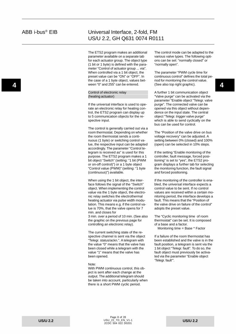
The ETS2 program makes an additionalparameter available on a separate tabfor each actuator group. The object type(1 bit or 1 byte) is defined with the para-meter “Control of actuator group ... via”.When controlled via a 1 bit object, thepreset value can be “ON” or “OFF”. Inthe case of a 1 byte object, values bet-ween “0” and 255” can be entered.
Control of electronic relay(heating actuator)
If the universal interface is used to ope-rate an electronic relay for heating con-trol, the ETS2 program can display upto 5 communication objects for the re-spective input.
The control is generally carried out via aroom thermostat. Depending on whetherthe room thermostat sends a conti-nuous (1 byte) or switching control va-lue, the respective input can be adaptedaccordingly. The parameter “Control te-legram is received as” is used for thispurpose. The ETS2 program makes a 1bit object “Switch” (setting: “1 bit (PWMor on-off control)”) or a 1 byte object“Control value (PWM)” (setting: “1 byte(continuous)”) available.
When using the 1 bit object, the inter-face follows the signal of the “Switch”object. When implementing the controlvalue via the 1 byte object, the electro-nic relay switches the electrothermalheating actuator via pulse width modu-lation. This means e.g. if the control va-lue is 70%, that the valve opens for 7min. and closes for3 min. over a period of 10 min. (See alsothe graphic on the previous page forcontrolling an electronic relay).
The current switching state of the re-spective channel is sent via the object“Telegr. status/ackn.”. A telegram withthe value “0” means that the valve hasbeen closed while a telegram with thevalue “1” means that the valve hasbeen opened.
Note:With PWM continuous control, this ob-ject is sent after each change at theoutput. The additional telegram shouldbe taken into account, particularly whenthere is a short PWM cyclic period.
The control mode can be adapted to thevarious valve types. The following opti-ons can be set: “normally closed” or“normally open”.
The parameter “PWM cycle time forcontinuous control” defines the total pe-riod for monitoring the control value.(See also top right graphic).
A further 1 bit communication object“Valve purge” can be activated via theparameter “Enable object “Telegr. valvepurge”. The connected valve can beopened via this object without depen-dence on the input state. The centralobject “Telegr. trigger valve purge”which is able to send cyclically on thebus can be used for control.
The “Position of the valve drive on busvoltage recovery” can be adjusted. Asetting between 0% (closed) and 100%(open) can be selected in 10% steps.
If the setting “Enable monitoring of thecontroller, fault message, forced posi-tioning” is set to “yes”, the ETS2 pro-gram displays a further tab for selectingthe monitoring function, the fault signaland forced positioning.
If the monitoring of the controller is ena-bled, the universal interface expects acontrol value to be sent. If no controlvalues are received within a certain mo-nitoring period, the interface develops afault. This means that the “Position ofthe valve drive on failure of the control”adopts the preset value.
The “Cyclic monitoring time of roomthermostat” can be set. It is composedof a base and a factor.
Monitoring time = Base * Factor
If a failure of the room thermostat hasbeen established and the valve is in thefault position, a telegram is sent via the1 bit object “Telegr. fault”. To do so, thefault object must previously be activa-ted via the parameter “Enable object‘Telegr. fault’”.

Page 9 of 28USU_22_TD_EN_V1-12CDC 504 022 D0201
ABB i-bus® EIB
US/U 2.2US/U 2.2
44
Universal Interface, 2-fold, FMUS/U 2.2, GH Q631 0074 R0111
The valve can be moved to a presetposition via the 1 bit communication ob-ject “Forced positioning”. Forced posi-tioning or the regular valve purge areused during the summer months, sothat deposits cannot build up on the val-ves. The “Valve position during forcedpositioning” can be set between 0%(closed) and 100% (opened).
Please take the order of priority forforced positioning, valve purge, faultoperation and normal control from thesecond graphic in the bottom right-handcorner.
LED control
When using the universal interface forcontrolling LEDs, a maximum of three 1bit communication objects are availablefor each channel. The object “Output ... -LED switching” is used by default toswitch on the connected LED. A tele-gram with the value “1” normally swit-ches the LED on while a telegram withthe value “0” switches it off again. Thebehaviour can be inverted with the pa-rameter “LED is switched ON, if ...”.
With a further object “Output ... - LEDpermanent ON”, the LED can be swit-ched on independently of the object“LED, switching”. This means that assoon as the object “LED permanentON” has the value “1”, the LED is swit-ched on, regardless of the value of theobject “LED, switching”.
If the LED functionality is modified from“switch ON/OFF” to “Flashing”, thecommunication object “Output ... - LED,switching” is replaced by the 1 bit object“Output ... - LED, flashing”. The settingin the parameter “LED flashes, if ...” de-termines whether a connected LEDstarts to flash with an ON or an OFFtelegram.
It is possible to select the period thatthe LED is switched ON or OFF forwhen it flashes. Both periods can be setseparately between 100 ms and60 ms.
It is possible to define a maximum ope-rating time. To do so, the time limit mustbe enabled with the parameter “Timelimit of LED control”. If “yes” is selected,the connected LED only remains swit-ched on after an ON command for theduration of the time limit. This limit ispreset with a base and a factor.
Time limit = Base * Factor
The current status of the LED is sentvia the object “Telegr. status/ackn.”. Theobject is however only activated if theparameter “Transmit status via object‘Telgr. status/ackn.’” has been set to“yes”.
Switching sequence (“latching relay”)
The use of the universal interface as astepping switch (“latching relay”) ena-bles the flexible switching on or off of upto five 1 bit communication objects via asingle input.
Both normally closed and normally opencontacts are connected to the respecti-ve input. If normally open contacts areused for example, the setting “Connec-ted contact type” must be set to “nor-mally open”.
The parameter “Number of objects” de-termines the number of objects. Thatmeans e.g. if “3 levels” are selected, theETS2 program displays three 1 bit ob-jects “Input ... - Value ...” for the respec-tive input.
Three different switching sequencescan be set. If “sequentially on/off (onepush button)” is set, the states of theobjects are modified according to thefollowing switching sequence (examplewith 3 levels):
…>000>001>011>111>011>001>…
If “on/off (several push buttons)” is sel-ected, the states of the objects onlychange in one direction when the pushbutton is pressed. It is possible toswitch upwards (increment) or switchdownwards (decrement). For this rea-son, at least two inputs are required forthese switching sequences: one for thefollowing switching sequences (examp-le with 3 levels):
000>001>011>111and the other switch sensor for the re-verse switching sequences (examplewith 3 levels):
111>011>001>000

Page 10 of 28USU_22_TD_EN_V1-12CDC 504 022 D0201
ABB i-bus® EIB
US/U 2.2US/U 2.2
44
Universal Interface, 2-fold, FMUS/U 2.2, GH Q631 0074 R0111
If “All combinations” is selected, thestates of the objects are modified ac-cording to the following switching se-quences (example with 3 levels):…>000>001>011>010>110>111>101>100>…It is thus guaranteed that the value ofonly one communication object is chan-ged between two switching levels.
The setting “Function on operation”(only activated for several push but-tons) defines whether an input signalswitches one level upwards or one leveldownwards.
The adjustable debounce time preventsthe unwanted contact bounce of con-ventional push buttons or switches fromhaving a negative effect.With the additional 1 bit communicaitonobject “Level increment/decrement”, it ispossible to switch upwards or down-wards via EIB telegrams. An ON tele-gram switches down one level while anOFF telegram switches up one level.
Push button with multiple operation
When used as a “Push button with mul-tiple operation”, the universal interfacecan detect multiple operations at therespective input. These multiple operati-ons are sent to a maximum of four 1 bitcommunication objects.
Both normally closed and normally opencontacts are connected to the respecti-ve input. If normally open contacts areused for example, the setting “Connec-ted contact type” must be set to “nor-mally open”.
The ETS2 program makes a large num-ber of objects available depending onthe “Max. number of operations”. Thismeans that if e.g. a “single operation“and a “2-fold operation” should be eva-luated, the setting “2-fold operation”should be selected. The ETS2 programdisplays two objects “Input ... - Telegr.operation ...-fold”.
The setting “Transmitted value (object‘Telegr. operation ...-fold’)” determineswhich value is sent after an operation(single, 2-fold, 3-fold or 4-fold). Thetransmitted value can be an ON, OFFor TOGGLE telegram.
The parameter “Transmit value on everyoperation” defines whether the interfaceevaluates the respective operationscompletely or confirms them individually.
Example:The “Max. number of operations” hasbeen defined as “3-fold operation”. Theparameter “Transmit value on everyoperation” is set to “no”. In this setting,the interface sends a telegram to theobject “Telegr. operation 1-fold” when asingle operation has been detected. Af-ter a 2-fold operation, a telegram is sentto the object “Telegr. operation2-fold” while a telegram is sent to thecorresponding object after a 3-fold ope-ration.If the parameter “Transmit value on eve-ry operation” is changed to “yes”, theinterface can send a telegram aftereach operation. This means that a tele-gram is triggered after a three-fold ope-ration to the objects “Telegr. operation 1-fold”, “Telegr. operation2-fold” and “Telegr. operation 3-fold”.
The “Maximum time between two ope-rations” indicates how long the interval(period) can be between multiple opera-tions so that it can still be considered amultiple operation.
It is possible to activate an additional1 bit object “Telegr. operation long” forthe evaluation of a long push button ac-tion. The period which is interpreted asa long operation by the input can be setbetween 0.3 s and 10 s. The transmittedvalue on detection of a long push buttonaction can be an ON, OFF or TOGGLEtelegram.
The adjustable debounce time preventsthe unwanted contact bounce of con-ventional push buttons or switches fromhaving a negative effect.
Pulse counter
When used as a pulse counter, the uni-versal interface can count up input si-gnals and send them on the EIB. De-pending on the parameter setting, up tofour communication objects are display-ed.
The parameter “Pulse detection on” de-termines whether input signals with afalling edge (normally closed contact) ora rising edge (normally open contact)are counted.

Page 11 of 28USU_22_TD_EN_V1-12CDC 504 022 D0201
ABB i-bus® EIB
US/U 2.2US/U 2.2
44
Universal Interface, 2-fold, FMUS/U 2.2, GH Q631 0074 R0111
The interface can send the counter va-lues in three sizes: as 8 bit values(0 … 255), 16 bit values (-32.768 …+32.767 or 0 …65.535) or as 32 bit va-lues (-2.147.483.648 …+2.147.483.647). Depending on the sizeof the bit value, the ETS2 program dis-plays an 8 bit, a 16 bit or a 32 bit com-munication object “Input ... - Telegr.counter value ... bytes”. The new coun-ter value is sent to this object after eachoperation at the input.
The initial counter values can be para-meterised. All counter values start withthe value “0” by default.
The current counter value can be re-quested at any time via the EIB with the1 bit object “Request counter values”.To do so, a telegram with the value “1”must be received. The objects “Input ... -Telegr. counter value ... bytes” and anenabled object “Input ... - Differentialcounter ... bytes” thus send their currentvalues, regardless of whether these va-lues have already been sent.
The adjustable debounce time preventsthe unwanted contact bounce of con-ventional push buttons or switches fromhaving a negative effect.
After a bus voltage failure, the currentcounter value can be sent directly onthe bus. To do so, the parameter “Trans-mit counter values after bus voltage re-covery” must be set accordingly. Afterbus voltage failure, the counter valuesare reset to their initial values.
A further tab is activated in the ETS2program via the setting “Enable additio-nal options”. Special functions can beset here when the interface is used as apulse counter.By default, the pulse counter recordsevery operation at its input. With the pa-rameter “Divider: number of input pulsesfor one counter step”, the countingfunction can be adapted to individualrequirements.
The setting “Factor: one counter stepchanges counter value by” indicateshow many steps are counted upwardson detection of a pulse. If a negative va-lue is entered, the counter counts back-wards.
If the counter values should be sent cy-clically, the corresponding parametershould be set to “yes”. The cyclic timeis composed of a base and a factor.
Cyclic time = Base * Factor
If the differential counter is activated,the ETS2 indicates three further com-munication objects. The object “Input ...- Differential counter ... bytes” alwayshas the same bit width as the countervalue object. The two objects “Input ... -Differential counter overflow” and “Input... - Reset differential counter” are 1 bitobjects.
The differential counter has the samecounting function as the absolute coun-ter. In contrast however, it can be resetvia the object “Input ... - Reset differenti-al counter”. In addition, a counter over-flow can be reported on the bus via theobject “Input ... - Differential counteroverflow”. It is thus possible e.g. tomeasure daily consumption values viathe differential counter.
The overflow value of the differentialcounter can be set. If the differentialcounter reaches the set value, a “1” issent to the object “Input ... - Differentialcounter overflow” and the differentialcounter starts to count from the begin-ning.

Page 12 of 28USU_22_TD_EN_V1-12CDC 504 022 D0201
ABB i-bus® EIB
US/U 2.2US/U 2.2
44
Universal Interface, 2-fold, FMUS/U 2.2, GH Q631 0074 R0111
Communication objectswhen used as a switch sensor
Communication objectswhen used as a switch sensor withdetection of long switch operations
Communication objectswhen used as a switch/dimming sensor
Communication objectswhen used only as a dimming sensor
Communication objectswhen used as a shutter sensor
Communication objectswhen using the channels for sendingvalues (1 byte)
Communication objectswhen using the channels for forcedoperation
Communication objectswhen using the channels for sendingvalues (2 byte)
No. Type Object name Function0 1 bit Input A Disable1 1 bit Input A Telegr. switch7 1 bit Input B Disable8 1 bit Input B Telegr. switch
No. Type Object name Function…
2 1 bit Input A - long Telegr. switch…
9 1 bit Input B - long Telegr. switch
No. Type Object name Function0 1 bit Input A Disable1 1 bit Input A -short Telegr. switch2 4 bit Input A Telegr. dimming7 1 bit Input B Disable8 1 bit Input B -short Telegr. switch9 4 bit Input B Telegr. dimming
No. Type Object name Function0 1 bit Input A Disable2 4 bit Input A Telegr. dimming7 1 bit Input B Disable9 4 bit Input B Telegr. dimming
No. Type Object name Function0 1 bit Input A Disable1 1 bit Input A Telegr. shutter UP/DOWN2 1 bit Input A Telegr. STOP / lamella adj.3 1 bit Input A Upper limit position4 1 bit Input A Lower limit position7 1 bit Input B Disable8 1 bit Input B Telegr. shutter UP/DOWN9 1 bit Input B Telegr. STOP / lamella adj.
10 1 bit Input B Upper limit position11 1 bit Input B Lower limit position
No. Type Object name Function0 1 bit Input A Disable1 1 byte Input A Telegr. value (0… 255)7 1 bit Input B Disable8 1 byte Input B Telegr. value (0… 255)
No. Type Object name Function…
1 2 bit Input A Telegr. value (forced position)…
1 2 bit Input B Telegr. value (forced position)
No. Type Object name Function…
1 2 byte Input A Telegr. value (-32768…32767)…
1 2 byte Input B Telegr. value (-32768…32767)

Page 13 of 28USU_22_TD_EN_V1-12CDC 504 022 D0201
ABB i-bus® EIB
US/U 2.2US/U 2.2
44
Universal Interface, 2-fold, FMUS/U 2.2, GH Q631 0074 R0111
No. Type Object name Function…
1 2byte Input A Telegr. value (0…65535)…
1 2byte Input B Telegr. value (0…65535)
No. Type Object name Function…
1 2byte Input A Telegr. value (temperature)…
1 2byte Input B Telegr. value (temperature)
No. Type Object name Function…
1 4byte Input A Telegr. value (0…4294967295)…
1 4byte Input B Telegr. value (0…4294967295)
No. Type Object name Function…
1 1byte Input A -short Telegr. value (0.1)2 1byte Input A -long Telegr. value (0…255)
…7 1byte Input B -short Telegr. value (forced position)8 1byte Input B -long Telegr. value (-32768…32767)
…
No. Type Object name Function0 1bit Input A Disable1 1bit Input A Telegr. switch actuator group A2 1bit Input A Telegr. switch actuator group B3 1bit Input A Telegr. switch actuator group C4 1bit Input A Telegr. switch actuator group D5 1bit Input A Telegr. switch actuator group E6 1bit Input A Store scene7 1bit Input B Disable8 1bit Input B Telegr. switch actuator group A9 1bit Input B Telegr. switch actuator group B
10 1bit Input B Telegr. switch actuator group C11 1bit Input B Telegr. switch actuator group D12 1bit Input B Telegr. switch actuator group E13 1bit Input B Store scene
No. Type Object name Function…
1 1byte Input A Telegr. switch actuator group A2 1byte Input A Telegr. switch actuator group B3 1byte Input A Telegr. switch actuator group C4 1byte Input A Telegr. switch actuator group D5 1byte Input A Telegr. switch actuator group E
…
Communication objectswhen using the channels for sendingvalues (2 byte)
Communication objectswhen using the channels for sendingvalues (floating point)
Communication objectswhen using the channels for sendingvalues (4 byte)
Communication objectswhen using the channels for sendingvalues with detection of long switchoperations
Communication objectswhen used for scene control (actuatorgroups)
Communication objectswhen used for scene control (8 bitscene)

Page 14 of 28USU_22_TD_EN_V1-12CDC 504 022 D0201
ABB i-bus® EIB
US/U 2.2US/U 2.2
44
Universal Interface, 2-fold, FMUS/U 2.2, GH Q631 0074 R0111
No. Type Object name Function0 1 bit Input A Disable1 1 byte Input A 8 bit scene6 1 bit Input A Store scene7 1 bit Input B Disable8 1 byte Input B 8 bit scene
13 1 bit Input B Store scene
No. Type Object name Function1 1 bit Output A Switch5 1 bit Output A Telegr. status/ackn.8 1 bit Output B Switch
12 1 bit Output B Telegr. status/ackn.
No. Type Object name Function1 1 byte Output A Control value (PWM)5 1 bit Output A Telegr. status/ackn.8 1 byte Output B Control value (PWM)
12 1 bit Output B Telegr. status/ackn.
No. Type Object name Function…
3 1 bit Output A Valve purge4 1 bit Output A Forced positioning
…6 1 bit Output A Telegr. fault
…3 1 bit Output B Valve purge4 1 bit Output B Forced positioning
…6 1 bit Output B Telegr. fault
…29 1 bit Output telegram Telegr. trigger valve purge
No. Type Object name Function1 1 bit Output A LED, switching3 1 bit Output A LED permanent ON8 1 bit Output B LED, switching
10 1 bit Output B LED permanent ON
No. Type Object name Function…
4 1 bit Output A Telegr. status/ackn.…11 1 bit Output B Telegr. status/ackn.
No. Type Object name Function1 1 bit Output A LED, flashing
…1 1 bit Output B LED, flashing
…
Communication objectswhen used for scene control (8 bitscene) with stored function
Communcation objectswhen used for controlling an electronicrelay (1 bit)
Communication objectswhen used for controlling an electronicrelay (1 byte)
Communication objectswhen used for controlling an electronicrelay with valve purging and forcedpositioning
Communication objectswhen used for controlling LEDs (swit-ching)
Communication objectswhen used for controlling an LED withstatus acknowledgement
Communication objectswhen used for controlling an LED(flashing)

Page 15 of 28USU_22_TD_EN_V1-12CDC 504 022 D0201
ABB i-bus® EIB
US/U 2.2US/U 2.2
44
Universal Interface, 2-fold, FMUS/U 2.2, GH Q631 0074 R0111
No. Type Object name Function0 1bit Input A Disable1 1bit Input A Value 12 1bit Input A Value 23 1bit Input A Value 36 1bit Input A Level increment/decrement7 1bit Input B Disable8 1bit Input B Value 19 1bit Input B Value 2
10 1bit Input B Value 313 1bit Input B Level increment/decrement
No. Type Object name Function…
4 1bit Input A Value 45 1bit Input A Value 5
…11 1bit Input B Value 412 1bit Input B Value 5
No. Type Object name Function0 1bit Input A Disable1 1bit Input A Telegr. operation 1-fold2 1bit Input A Telegr. operation 2-fold3 1bit Input A Telegr. operation 3-fold7 1bit Input B Disable8 1bit Input B Telegr. operation 1-fold9 1bit Input B Telegr. operation 2-fold
10 1bit Input B Telegr. operation 3-fold
No. Type Object name Function…
4 1bit Input A Telegr. operation 4-fold6 1bit Input A Telegr. operation long
…11 1bit Input B Telegr. operation 4-fold13 1bit Input B Telegr. operation long
No. Type Object name Function0 1bit Input A Disable1 4byte Input A Telegr. counter value 4 bytes3 1bit Input A Request counter values7 1bit Input B Disable8 4byte Input B Telegr. counter value 4 bytes
10 1bit Input B Request counter values
No. Type Object name Function…
2 4byte Input A Differential counter 4 bytes…
4 1bit Input A Differential counter overflow5 1bit Input A Reset differential counter
…9 4byte Input B Differential counter 4 bytes
…11 1bit Input B Differential counter overflow12 1bit Input B Reset differential counter
Communication objectswhen used as an input for switchingsequences (“latching relay”)(3 levels)
Communication objectswhen used for switching sequences(“latching relay”) (5 levels)
Communication objectswhen used as a push button withmultiple operations (3-fold)
Communication objectswhen used as a push button withmultiple operations (4-fold) and detectionof long switch operations
Communication objectswhen used as a pulse counter (4 byte)
Communication objectswhen used as a pulse counter (4 byte)with overflow and reset function

Page 16 of 28USU_22_TD_EN_V1-12CDC 504 022 D0201
ABB i-bus® EIB
US/U 2.2US/U 2.2
44
Universal Interface, 2-fold, FMUS/U 2.2, GH Q631 0074 R0111
No. Type Object name Function…
1 2 byte Input A Telegr. counter value 2 bytes2 2 byte Input A Request counter values
…8 2 byte Input B Telegr. counter value 2 bytes9 2 byte Input B Request counter values
No. Type Object name Function…
1 1 byte Input A Telegr. counter value 1 byte2 1 byte Input A Request counter values
…8 1 byte Input B Telegr. counter value 1 byte9 1 byte Input B Request counter values
Communication objectswhen used as a pulse counter (2 byte)
Communication objectswhen used as a pulse counter (1 byte)
Page 17 of 28USU_22_TD_EN_V1-12CDC 504 022 D0201
ABB i-bus® EIB
US/U 2.2US/U 2.2
44
Universal Interface, 2-fold, FMUS/U 2.2, GH Q631 0074 R0111
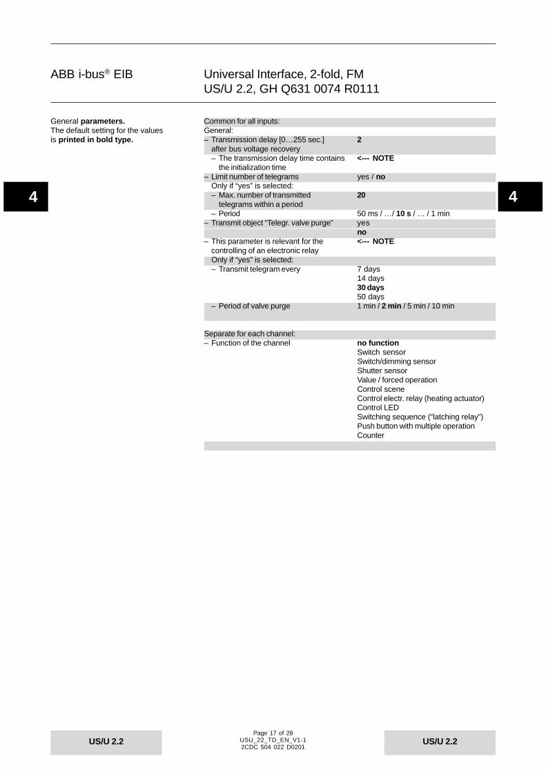
Common for all inputs:General:– Transmission delay [0…255 sec.] 2
after bus voltage recovery– The transmission delay time contains <--- NOTE
the initialization time– Limit number of telegrams yes / no
Only if “yes” is selected:– Max. number of transmitted 20
telegrams within a period– Period 50 ms / …/ 10 s / … / 1 min
– Transmit object “Telegr. valve purge” yesno
– This parameter is relevant for the <--- NOTEcontrolling of an electronic relayOnly if “yes” is selected:– Transmit telegram every 7 days
14 days30 days50 days
– Period of valve purge 1 min / 2 min / 5 min / 10 min
Separate for each channel:– Function of the channel no function
Switch sensorSwitch/dimming sensorShutter sensorValue / forced operationControl sceneControl electr. relay (heating actuator)Control LEDSwitching sequence (“latching relay”)Push button with multiple operationCounter
General parameters.The default setting for the valuesis printed in bold type.

Page 18 of 28USU_22_TD_EN_V1-12CDC 504 022 D0201
ABB i-bus® EIB
US/U 2.2US/U 2.2
44
Universal Interface, 2-fold, FMUS/U 2.2, GH Q631 0074 R0111
Only when used as a switch sensor:– Distinction between long and short yes / no
operationOnly if “yes” is selected:– Connected contact type normally closed
normally open– Reaction on short operation ON / OFF / TOGGLE / no reaction– Reaction on long operation ON / OFF / TOGGLE / no reaction– Long operation after: Base 100 ms / 1 s / … / 1 min / … / 1 h– Factor (2…255) 5– Number of objects for short/long 1 object
operation 2 objects– Debounce time 10 ms debounce time / … /
50 ms debounce time /150 ms debounce time
Only if “no” is selected:– Cyclic transmission of object no
“Telegr. switch” if “switch” = ONif “switch” = OFFalways
– Reaction on closing the contact ON (rising edge) OFF
TOGGLEno reactionterminate cyclic transmission
– Reaction on opening the contact ON (falling edge) OFF
TOGGLEno reactionterminate cyclic transmission
Only for cyclical sending:– Telegram is repeated every 100 ms / 1 s / … / 1 min / … / 1 h (“transmission cycle time”): base– Factor (1…255) 30
– Transmit object value after yes / nobus voltage recovery
– Debounce time / 10 ms debounce timemin. operation time …
50 ms debounce time…150 ms debounce timeMinimum operation time
Parameters when used as a switchsensor. The default setting for the valu-es is printed in bold type.

Page 19 of 28USU_22_TD_EN_V1-12CDC 504 022 D0201
ABB i-bus® EIB
US/U 2.2US/U 2.2
44
Universal Interface, 2-fold, FMUS/U 2.2, GH Q631 0074 R0111
Only when used as a switch/dimming sensor:– Connected contact type normally closed
normally open– Dimming functionality Dimming and switching
Only dimmingFor dimming and switching:– Reaction on short operation ON / OFF / TOGGLE / no reaction– Reaction on long operation Dim BRIGHTER
Dim DARKERDim BRIGHTER/DARKER
– Long operation after 0.3 s / 0.4 s / 0.5 s / … / 10 sFor dimming only:– Reaction on operation Dim BRIGHTER
Dim DARKERDim BRIGHTER/DARKER
– Dimming mode Start-stop dimmingDimming steps
Only for dimming steps:– Brightness change on every 100 % / 50 % / 25 % / 12.5 % / 6.25 %
sent telegram / 3.13 % / 1.56 %– Transmission cycle time: telegram 0.3 s / 0.4 s / 0.5 s / … / 10 s
is repeated everyFor dimming and switching:– Debounce time 10 ms debounce time / … /
50 ms debounce time /150 ms debounce time
For dimming only:– Debounce time / 10 ms debounce time
min. operation time …50 ms debounce time…150 ms debounce timeMinimum operation time
Parameters when used as as switch/dimming sensor. The default setting forthe values is printed in bold type.

Page 20 of 28USU_22_TD_EN_V1-12CDC 504 022 D0201
ABB i-bus® EIB
US/U 2.2US/U 2.2
44
Universal Interface, 2-fold, FMUS/U 2.2, GH Q631 0074 R0111
Only when used as a shutter sensor:– Operating functionality of blind 1 push button, short = stepping,
long = moving1 push button, short = moving,long = stepping1 push button operation, moving1 switch operation, moving2 push button, standard2 switch operation, moving (shutter)2 push button, moving (shutter)2 push button, stepping
Only for 1 push button, short = stepping, long = moving:– Long operation: move UP/DOWN <--- Note about functionality
Short operation: Lamella– Connected contact type normally closed
normally open– Long operation after 0.3 s / 0.4 s / 0.5 s / … / 10 s– Debounce time 10 ms debounce time / … /
30 ms debounce time /150 ms debounce time
Only for 1 push button, short = moving, long = stepping:– Long operation: Lamella <--- Note about functionality
Short operation: move UP/DOWN– Connected contact type normally closed
normally open– Long operation after 0.3 s / 0.4 s / 0.5 s / … / 10 s– “Telegr. STOP/lamella adj.” is 0.3 s / 0.4 s / 0.5 s / … / 10 s
repeated every– Debounce time 10 ms debounce time / … /
30 ms debounce time /150 ms debounce time
Only for 1 push button operation, moving:– On every operation in succession <--- Note about functionality
UP - STOP - DOWN - STOP– Connected contact type normally closed
normally open– Debounce time 10 ms debounce time / … /
30 ms debounce time /150 ms debounce time
Only for 1 switch operation, moving:– On operation: UP/DOWN, <--- Note about functionality
end of operation: STOP– Connected contact type normally closed
normally open– Debounce time 10 ms debounce time / … /
30 ms debounce time /150 ms debounce time
Only for 2 push button, standard:– Short operation: STOP/Lamella UP/DOWN <--- Note about functionality
Long operation: move UP/DOWN– Connected contact type normally closed
normally open– Reaction on short operation STOP / Lamella UP
STOP / Lamella DOWN– Reaction on long operation MOVE UP
MOVE DOWN– Long operation after 0.3 s / 0.4 s / 0.5 s / … / 10 s– Debounce time 10 ms debounce time / … /
30 ms debounce time /150 ms debounce time
Parameters when used as a shuttersensor. The default setting for the valu-es is printed in bold type.

Page 21 of 28USU_22_TD_EN_V1-12CDC 504 022 D0201
ABB i-bus® EIB
US/U 2.2US/U 2.2
44
Universal Interface, 2-fold, FMUS/U 2.2, GH Q631 0074 R0111
Only for 2 switch operation, moving (shutter):– On operation: moving, <--- Note about functionality
end of operation: STOP– Connected contact type normally closed
normally open– Reaction on operation MOVE UP
MOVE DOWN– Debounce time 10 ms debounce time / ... /
30 ms debounce time /150 ms debounce time
Only for 2 push button, moving (shutter):– On operation: moving <--- Note about functionality– Connected contact type normally closed
normally open– Reaction on operation MOVE UP
MOVE DOWN– Debounce time 10 ms debounce time / … /
30 ms debounce time /150 ms debounce time
Only for 2 push button, stepping:– On operation: stepping <--- Note about functionality– Connected contact type normally closed
normally open– Reaction on operation STOP / Lamella UP
STOP / Lamella DOWN– “Telegr. STOP/lamella adj.” is 0.3 s / 0.4 s / 0.5 s / … / 10 s
repeated every– Debounce time 10 ms debounce time / … /
30 ms debounce time /150 ms debounce time
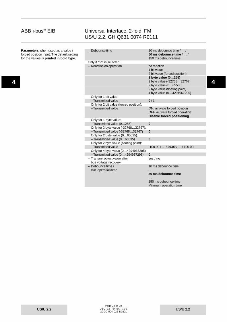
Only when used as a value / forced position input:– Connected contact type normally closed
normally open– Distinction between long and short yes / no
operationOnly if “yes” is selected:Separate for short/long operation:– Reaction on short (long) no reaction
operation 2 bit value (forced position)1 byte value (0…255)2 byte value (-32768…32767)2 byte value (0…65535)2 byte value (floating point)4 byte value (0…4294967295)
Only for 2 bit value (forced position):– Transmitted value ON, activate forced position
OFF, activate forced operationDisable forced positioning
Only for 1 byte value:– Transmitted value (0…255) 0Only for 2 byte value (-32768…32767):– Transmitted value (-32768…32767) 0Only for 2 byte value (0…65535):– Transmitted value (0…65535) 0Only for 2 byte value (floating point):– Transmitted value -100.00 / … / 20.00 / … / 100.00Only for 4 byte value (0…4294967295):– Transmitted value (0…4294967295) 0
– Long operation after: Base 100 ms / 1 s / … / 1 h– Factor (2…255) 4
Parameters when used as a shuttersensor. The default setting for the valu-es is printed in bold type.
Parameters when used as a value /forced position input. The default settingfor the values is printed in bold type.
Page 22 of 28USU_22_TD_EN_V1-12CDC 504 022 D0201
ABB i-bus® EIB
US/U 2.2US/U 2.2
44
Universal Interface, 2-fold, FMUS/U 2.2, GH Q631 0074 R0111
– Debounce time 10 ms debounce time / … /50 ms debounce time / … /150 ms debounce time
Only if “no” is selected:– Reaction on operation no reaction
1 bit value2 bit value (forced position)1 byte value (0…255)2 byte value (-32768…32767)2 byte value (0…65535)2 byte value (floating point)4 byte value (0…4294967295)
Only for 1 bit value:– Transmitted value 0 / 1Only for 2 bit value (forced position):– Transmitted value ON, activate forced position
OFF, activate forced operationDisable forced positioning
Only for 1 byte value:– Transmitted value (0…255) 0Only for 2 byte value (-32768…32767):– Transmitted value (-32768…32767) 0Only for 2 byte value (0…65535):– Transmitted value (0…65535) 0Only for 2 byte value (floating point):– Transmitted value -100.00 / … / 20.00 / … / 100.00Only for 4 byte value (0…4294967295):– Transmitted value (0…4294967295) 0
– Transmit object value after yes / nobus voltage recovery
– Debounce time / 10 ms debounce timemin. operation time …
50 ms debounce time…150 ms debounce timeMinimum operation time
Parameters when used as a value /forced position input. The default settingfor the values is printed in bold type.

Page 23 of 28USU_22_TD_EN_V1-12CDC 504 022 D0201
ABB i-bus® EIB
US/U 2.2US/U 2.2
44
Universal Interface, 2-fold, FMUS/U 2.2, GH Q631 0074 R0111
Only when used for controlling scenes:– Connected contact type normally closed
normally open– Control the scene via 5 separate objects
8 bit sceneOnly for 8 bit scene:– No. of scene (0…63) 0
– Reaction on short operation no reactionRecall scene
– Store scene noon long operationwith object value = 1on long operation(if object value = 1)
– Long operation after 0.3 s / … / 3 s / … / 10 s– Debounce time 10 ms debounce time / … /
50 ms debounce time /150 ms debounce time
Only for 5 separate objects, separate for each actuator group:– Control of actuator group … via 1 bit object
8 bit objectOnly for 1 bit object:– Preset value actuator group … ON / OFFOnly for 1 byte object:– Preset value actuator group … 0
Parameters when used for controllingscenes. The default setting for the valu-es is printed in bold type.
Page 24 of 28USU_22_TD_EN_V1-12CDC 504 022 D0201
ABB i-bus® EIB
US/U 2.2US/U 2.2
44
Universal Interface, 2-fold, FMUS/U 2.2, GH Q631 0074 R0111
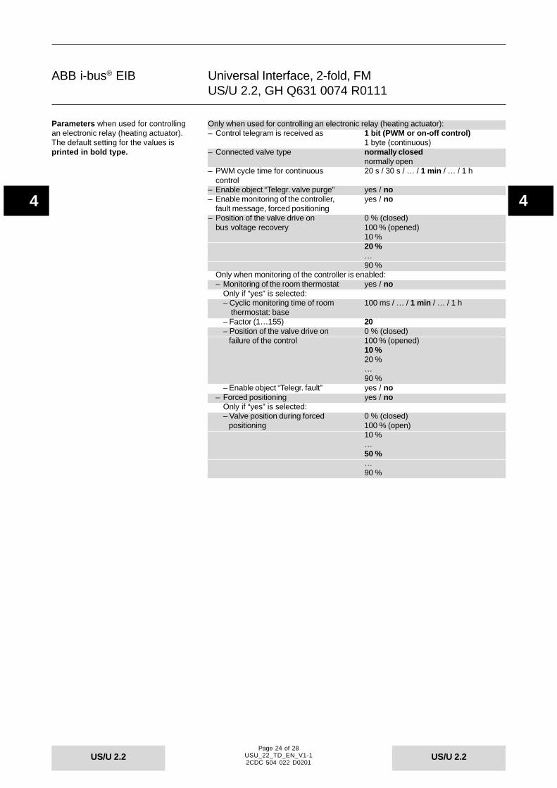
Only when used for controlling an electronic relay (heating actuator):– Control telegram is received as 1 bit (PWM or on-off control)
1 byte (continuous)– Connected valve type normally closed
normally open– PWM cycle time for continuous 20 s / 30 s / … / 1 min / … / 1 h
control– Enable object “Telegr. valve purge” yes / no– Enable monitoring of the controller, yes / no
fault message, forced positioning– Position of the valve drive on 0 % (closed)
bus voltage recovery 100 % (opened)10 %20 %…90 %
Only when monitoring of the controller is enabled:– Monitoring of the room thermostat yes / no
Only if “yes” is selected:– Cyclic monitoring time of room 100 ms / … / 1 min / … / 1 h thermostat: base– Factor (1…155) 20– Position of the valve drive on 0 % (closed) failure of the control 100 % (opened)
10 %20 %…90 %
– Enable object “Telegr. fault” yes / no– Forced positioning yes / no
Only if “yes” is selected:– Valve position during forced 0 % (closed) positioning 100 % (open)
10 %…50 %…90 %
Parameters when used for controllingan electronic relay (heating actuator).The default setting for the values isprinted in bold type.

Page 25 of 28USU_22_TD_EN_V1-12CDC 504 022 D0201
ABB i-bus® EIB
US/U 2.2US/U 2.2
44
Universal Interface, 2-fold, FMUS/U 2.2, GH Q631 0074 R0111
Only when used for controlling LED:– LED functionality switch ON/OFF
FlashingOnly for “switch ON/OFF”:– LED is switched ON, if Object “Telegr. switch” = 1
Object “Telegr. switch” = 0Only for “Flashing”:– LED flashes, if Object “LED flashing” = 1
Object “LED flashing” = 0– LED is switched ON for 200 ms / … / 1 s / … / 60 s– LED is switched OFF for 200 ms / … / 1 s / … / 60 s
– Time limit of LED control yes / noOnly if “yes” is selected:–Time limit: base 100 ms / 1 s / 10 s / … / 1 h– Time limit: factor (1…255) 5
– Transmit status via object yes / no“Telegr. status/ackn.”
– Status of LED on bus voltage OFF / ONrecovery
Only when used for switching sequences (“latching relay”):– Connected contact type normally closed
normally open– Number of objects 2 levels
3 levels4 levels5 levels
– Type of switching sequence sequentially on/off (one push button)on/off (several push buttons)All combinations
With only one push button:– Example for switching sequence <--- NOTE…>000>001>011>111>011>001>000>…With several push buttons:– Example for switching sequence <--- NOTE
000>001>011>111– Function on operation switch upwards
switch downwardsOnly for all combinations:– Example for switching sequence <--- NOTE…>000>001>011>010>110>111>101>…– Debounce time / 10 ms debounce time
min. operation time …50 ms debounce time…150 ms debounce timeMinimum operation time
Parameters when used for controllingLEDs. The default setting for the valuesis printed in bold type.
Parameters when used for switchingsequences. The default setting for thevalues is printed in bold type.

Page 26 of 28USU_22_TD_EN_V1-12CDC 504 022 D0201
ABB i-bus® EIB
US/U 2.2US/U 2.2
44
Universal Interface, 2-fold, FMUS/U 2.2, GH Q631 0074 R0111
Only when used as a push button with multiple operation:– Connected contact type normally open
normally closed– Max. number of operations single operation
(= number of objects) 2-fold operation3-fold operation4-fold operation
– Transmitted value ON / OFF / TOGGLE(object “Telegr. operation ...-fold“)
– Transmit value on every operation yes / no– Maximum time between two 0.3 s / … / 1 s / … /10 s
operations– Additional object for long operation yes / no
Only if “yes” is selected:– Long operation after 0.3 s / … / 0.5 s / … /10 s– Transmitted value ON / OFF / TOGGLE
(object “Telegr. operation long”)– Debounce time 10 ms debounce time / … /
50 ms debounce time / … /150 ms debounce time
Parameters when used as a push but-ton with multiple operation. The defaultsetting for the values is printed in boldtype.

Page 27 of 28USU_22_TD_EN_V1-12CDC 504 022 D0201
ABB i-bus® EIB
US/U 2.2US/U 2.2
44
Universal Interface, 2-fold, FMUS/U 2.2, GH Q631 0074 R0111
Only when used as a pulse counter:– Pulse detection on closing contact (rising edge)
opening contact (falling edge)– Data width of counter 8 bit (0…255)
16 bit (-32.768…32.767)16 bit (0…65.535)32 bit (-2.147.483.648…2.147.483.647)
Only for 8 bit:– Counter starts at 0
(0…255)Only for 16 bit (-32.768…32.767):– Counter starts at 0
(-32.768…32.767)Only for 16 bit (0…65.535):– Counter starts at 0
(0…65.535)Only for 32 bit (-2.147.483.648…2.147.483.647):– Counter starts at 0
(-2.147.483.648…2.147.483.647)– Debounce time / 10 ms debounce time
min. operation time …50 ms debounce time…150 ms debounce timeMin. operation time
– The debounce time must be shorter <--- NOTEthan the pulse period of the input signal
– Transmit counter values after yes / nobus voltage recovery
– Enable additional options yes / no(factor/divider, cyclical transmission)Only if additional options are enabled:– Divider: number of input pulses for 1
one counter step (1…32767)– Factor: one counter step changes 1
counter value by (-32768…32767)– Transmit counter values cyclically yes / no
Only if “yes” is selected:– Counter values are being 1 s / … / 1 h transmitted every: Base– Factor (1…255) 30
– Enable differential counter yes / noOnly if “yes” is selected:– Over-/underrun of differential 1000 counter at (-2147483648… 2147483647)– The overrun value must be greater <--- NOTE than the factor
Parameters when used as a pulsecounter. The default setting for the valu-es is printed in bold type.
Page 28 of 28USU_22_TD_EN_V1-12CDC 504 022 D0201
ABB i-bus® EIB
US/U 2.2US/U 2.2
44
Universal Interface, 2-fold, FMUS/U 2.2, GH Q631 0074 R0111