abb medium voltage drives acs2000 4kv frames 1, 2, & 3 ... · abb medium voltage drives acs2000...
TRANSCRIPT

ABB Medium Voltage DrivesACS2000 4kV Frames 1, 2, & 3Spare Parts Catalog

2 ACS2000 spare parts manual
General Manuals
ACS2000 User’s Manual − Safety − Power Electronics and Cabinet Features − Control System − Transportation, Storage and Disposal − Mechanical Installation − Electrical Installation − Commissioning − Local Operation − CDP Control Panel − Troubleshooting and Maintenance
ACS2000 Appendices − Maintenance Schedule − Fieldbus Adapters − Technical Data − Mechanical Drawings − Electrical Drawings − Spare Parts Manual − MV Switchgear Guide − Cable Specification − Induction Motor Specification − Pulse Encoder − Motor Temperature Supervision − Signal and Parameter Table − Troubleshooting Guide − DriveMonitorTM Manual
ACS 2000 Drive Manuals

ACS2000 spare parts manual 3
Table of contents
Safety ........................................................................................................................... 4
Drive Identification .................................................................................................................. 5
Master spare parts list ............................................................................................................ 7
Common Spare Parts - All Frames
Overview.................................................................................................................................12
Incoming/Control section
Front door...........................................................................................................13
Control swing frame............................................................................................14
Frame 1
Enclosure design....................................................................................................................16
Incoming/Control section ........................................................................................................17
IFU Section ...........................................................................................................................18
Resistor box assembly components ...................................................................19
Inductor stack ....................................................................................................20
Phase module section ............................................................................................................21
NP Frame............................................................................................................22
Frame 2
Enclosure design.................................................................................................................... 22
Incoming/Control section........................................................................................................ 24
IFU Section
Right cabinet (Left Side) ................................................................................... 25
Right cabinet (Right Side).................................................................................. 26
Filter assembly.................................................................................................... 27
Left cabinet........................................................................................................ 28
Resistor box assembly........................................................................................ 29
Phase Module Section
NP Frame........................................................................................................... 30
Front................................................................................................................... 32
Frame 3
Enclosure design......................................................................................................................33
Incoming/Control section..........................................................................................................36
IFU Section
Right cabinet (front) ..............................................................................................37
Right cabinet (rear) ...............................................................................................38
Filter assembly .....................................................................................................39
Resistor box assembly .........................................................................................40
Phase module section ..............................................................................................................41
NP Frame..............................................................................................................42
Integral Disconnect
Enclosure design.......................................................................................................................43
Closed front panel......................................................................................................................44
Open front panel........................................................................................................................46
Transformer section................................................................................................47
Top and bottom panel compartments.........................................................................................48

4 ACS2000 spare parts manual
Safety
DANGER indicates a hazardous situation which, if not avoided, will resultin death or serious injury.
Meaning of safety instructionsSafety instructions are used to highlight a potential hazard when working on the equipment. Safety instructions must be strictly followed! Noncompliance can jeopardize the safety of personnel, the equipment and the environment.
DANGER
WARNING indicates a hazardous situation which, if not avoided, couldresult in death or serious injury.
WARNING
CAUTION indicates a hazardous situation which, if not avoided, couldresult in minor or moderate injury.
CAUTION
NOTICE is used to address practices not related to personal injury.
NOTICE
The safety instructions are derived from the following standards:
– ISO 3864-2:2004 (E)
Graphical symbols – Safety colors and safety signs – Part 2: Design principles for product safety labels
– ANSI Z535.6
American National Standard for Product Safety Information in Product Manuals, Instructions, and Other Collateral Materials

ACS2000 spare parts manual 5
Drive Identification
To determine the proper spare parts, refer to the serial number nameplate attached to the inner door of the input/control section.
The ACS2000 is currently available in three frame sizes. Frame 1 is available beginning at 300HP and ranges up to 1000HP, while Frame 2 is available from 1250HP to 2000HP, and Frame 3 is available from 2250HP to 3000HP.
The chart below shows the rated input current and kW relative to the specific horse power rating for all drives in all frame sizes.
Base Type Code Frame
Rated Input
Current [kW] [hp]ACS 2040-1x-AN1-a-0C F1 40 224 300
ACS 2040-1x-AN1-a-0D F1 47 261 350
ACS 2040-1x-AN1-a-0E F1 54 298 400
ACS 2040-1x-AN1-a-0F F1 61 336 450
ACS 2040-1x-AN1-a-0H F1 67 373 500
ACS 2040-1x-AN1-a-0L F1 81 447 600
ACS 2040-1x-AN1-a-0Q F1 94 522 700
ACS 2040-1x-AN1-a-0R F1 108 597 800
ACS 2040-1x-AN1-a-0T F1 121 671 900
ACS 2040-1x-AN1-a-0V F1 135 746 1,000
ACS 2040-2x-AN1-a-0Z F2 185 933 1,250
ACS 2040-2x-AN1-a-1C F2 222 1,119 1,500
ACS 2040-2x-AN1-a-1F F2 260 1,306 1,750
ACS 2040-2x-AN1-a-1H F2 269 1,492 2,000
ACS 2040-3x-AN1-a-1J F3 303 1,679 2,250
ACS 2040-3x-AN1-a-1N F3 337 1,856 2,500
ACS 2040-3x-AN1-a-2A F3 370 2,052 2,750
ACS 2040-3x-AN1-a-2B F3 404 2,238 3,000
6 ACS2000 spare parts manual
Drive Identification
Type Designation A C S 2 0 4 0 1 L 1NA x xa
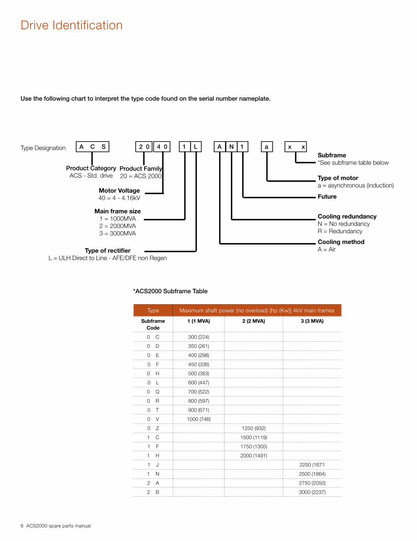
Product CategoryACS - Std. drive
Product Family20 = ACS 2000
Motor Voltage40 = 4 - 4.16kV
Main frame size1 = 1000MVA2 = 2000MVA3 = 3000MVA
Type of rectifierL = ULH Direct to Line - AFE/DFE non Regen
Subframe*See subframe table below
Type of motora = asynchronous (induction)
Future
Cooling redundancyN = No redundancyR = Redundancy
Cooling methodA = Air
Use the following chart to interpret the type code found on the serial number nameplate.
Type Maximum shaft power (no overload) [hp (Kw)] 4kV main frames
Subframe Code
1 (1 MVA) 2 (2 MVA) 3 (3 MVA)
0 C 300 (224)
0 D 350 (261)
0 E 400 (298)
0 F 450 (336)
0 H 500 (383)
0 L 600 (447)
0 Q 700 (522)
0 R 800 (597)
0 T 900 (671)
0 V 1000 (746)
0 Z 1250 (932)
1 C 1500 (1119)
1 F 1750 (1305)
1 H 2000 (1491)
1 J 2250 (1671
1 N 2500 (1864)
2 A 2750 (2050)
2 B 3000 (2237)
*ACS2000 Subframe Table

ACS2000 spare parts manual 7
ACS2000 4kV spare partsMaster list
Power electronicsSemiconductors
2UEA001345 Phase Module Kit Phase Module with Removal Tool x 21
2UEA002570 Phase Module Kit Phase Module with Removal Tool x 32
2UEA003021 Phase Module Kit Phase Module and Removal Tool x 34, 41
2UEA003051 Crowbar Stack Assembly Crowbar Assembly x 22
2UAE003063 Crowbar Stack Assembly Crowbar Assembly x 26
2UEA003031 Crowbar Stack Assembly Crowbar Assembly x 35
2UEA000911 Diode Clamp Diode Clamp x x x 22, 31, 42
Resistors
3BHB024326R0001 NP Grounding Filter Assembly Filter x x x 19, 27, 39
2UEA000360 Resistor, Clamp Clamp Resistor x x 22, 31
2UEA001469 Resistor, Clamp Clamp Resistor x 42
2UEA000893 Resistor, DC Link Symmetry Resistor x 22
2UEA001348 Resistor, DC Link Symmetry Resistor x 26
2UEA001470 Resistor, DC Link Symmetry Resistor x 38
2UEA000993 Resistor, IFU IFU Resistor x 19
2UEA001350 Resistor, IFU IFU Resistor x 29
2UEA001467 Resistor, IFU IFU Resistor x 40
2UEA000711 Resistor, CM Filter IFU Resistor x 19
2UEA001407 Resistor, CM Filter IFU Resistor x x 25, 40
2UEA000004 Resistor, EMC Filter EMC Resistor x 19
2UEA001505 Resistor, EMC Filter EMC Resistor x 29
2UEA001472 Resistor, EMC Filter EMC Resistor x 40
Capacitors
2UEA000005 Capacitor, EMC Filter EMC Capacitor x 19
2UEA001404 Capacitor, EMC Filter EMC Capacitor x 28
2UEA001464 Capacitor, EMC Filter EMC Capacitor x
2UEA000358 Capacitor, DC Link DC Link x 21
2UEA001406 Capacitor, DC Link DC Link x 26
2UEA001466 Capacitor, DC Link DC Link x 34
2UEA000357 Capacitor, Clamp Clamp x 22
2UEA001405 Capacitor, Clamp Clamp x 31
2UEA001465 Capacitor, Clamp Clamp x 35
2UEA000992 IFU Capacitor IFU Capacitor x 19
2UEA001352 IFU Capacitor IFU Capacitor x 27, 28
2UEA001463 IFU Capacitor IFU Capacitor x 35, 38
3BHB020698R0010 NP Grounding Capacitor Grounding Capacitor x x x 19,27,39
Inductors
2UEA001899 Transformer Transformer, 4160V to 480V; 15KVA x x x 47
2UEA001900 Transformer Transformer, 4160V to 480V; 20KVA x x 47
2UEA002611 Transformer Transformer 480V to 120V; 2KVA x x x x
2UEA002918 Inductor Stack Kit Inductor Stack kit with Base x 20
2UEA003159 Inductor Stack Kit Inductor Stack kit with Base x 28
2UEA003164 Inductor Stack Kit Inductor Stack kit with Base x 38
2UEA000883 Inductor, Clamp Clamp Inductor x 22
2UEA001403 Inductor, Clamp Clamp Inductor x 31
See Note 2 on page 49
2UEA003213 Inductor, Clamp Clamp Inductor x 42
See Note 2 on page 49
2UEA002974 Inductor, Clamp Clamp Inductor x 42
Category ACS2000 4KV Part Type Description F1 F2 F3 Disc Page

8 ACS2000 spare parts manual
ACS2000 4kV spare parts listMaster list
Category ACS2000 4KV Part Type Description F1 F2 F3 Disc Page
2UEA003165 Inductor, Common Mode Common Mode Inductor x 34, 37
2UEA000886 Inductor, EMC Filter InductorEMC Filter Inductor (SN<2124903744)
x 20
2UEA003160 Inductor, EMC Filter Inductor EMC Filter Inductor x 28
2UEA003166 Inductor, EMC Filter Inductor EMC Filter Inductor x 34, 37
2UEA002349 Inrestor Inrestor x 20
2UEA003150 Inrestor Inrestor x 26
2UEA002348 Inrestor Inrestor x 34
Charging unit
2UEA000967 High Voltage Relay High Voltage Relay x x x 19,27,39
2UEA000138 Charging transformer 400/460V, 4200V Charging Transformer x x x 19,28,38
Circuit Protection
2UEA001267 Fuse 70 Amp Power Fuse (300 - 400 HP) x x 17,47
2UEA001268 Fuse 140 Amp Power Fuse (450 - 700; 1250 HP) x x x 17,24,47
2UEA002203 Fuse, 160 Amp Power Fuse (1500-1750 HP) x x 24,47
2UEA000093 Fuse 200 Amp Power Fuse (800 - 1000; 2000 HP) x x x 17,24
2UEA001947 Fuse 230 Amp Power Fuse (2250 - 3000 HP) x x 36
2UEA002431 Fuse Fuse, MV, 4A x 47
2UEA001927 Fuse Fuse, 3.2A x 48
2UEA000149 Surge Arrestor Surge Arrestor x x x 17,24,36
Control electronics
Printed circuit boards
3BHE024577R0101 PP C907 BE: AMC 34 - PCB Varnished Application and Motor Control x x x 15
3BHE024855R0101 UF C921 A101: INT-2 Board Varnished Interface board x x x 15
3BHE024747R0101 Crowbar Board Crowbar Board x x x 22,26
3BHE032285R0102 HVD Board Varnished. High Voltage Divider x x x 19,27,39
3BHE009017R0102VLSCD-Board, Coated, Type XV C724 BE
Short Circuit Detection x x x 22,31,42
3BHE005555R0101 LD SYN-01 Sync Board x x x 19,27,39
3BHE020959R0127 IPS Single Voltage 27V IGBT Power Supply x x x 19,27,39
3BHE006373R0101 OEI-Board Optical Electrical Interface x x x 19,27,39
I/Os
3BHB003041R0101 IOEC IO IO Module x x x 15
2UEA000843 IOEC Connector-3 Position IO Module x x x 15
2UEA000861 IOEC Connector-7 Position IO Module x x x 15
2UEA000845 IOEC Connector-10 Position IO Module x x x 15
*Long lead item 2UEA003570 Intellivac Intellivac x x x x 48
2UEA001919 Motor Management Relay Motor Management Relay x x x x
2UEA003092 Motor Management Relay Motor Management Relay x x x x
Transducers
2UEA000988 Current Transducer LEM CT x 19
2UEA001456 Current Transducer LEM CT x 25
2UEA002111 Current Transducer LEM CT x 38
2UEA001894 Current TransducerCurrent Transducer (500A) Frame 1&2
x x x 45
2UEA003040 Current Transducer Current Transducer (1000A) Frame 3 x x 45
Power supplies
2UEA002224 Power Supply+24VDC Main Power Supply, 40A 480AC
x x x 15
2UEA002709 Power Supply +24VDC Main Power Supply, 120/240AC (+SPC01)
x x x 15

ACS2000 spare parts manual 9
ACS2000 4kV spare partsMaster list
2UEA000936 20A 3 Phase Buffer Module Power Supply x x x 15
2UEA001961 UPS, 24VDC, 40 Amp Power Supply (+CPR02) x x x 15
3BHE032593R0002 IPS Power Supply IGBT Power Supply x x x 19,26,34
2UEA001960 Battery, 24VDC, 12 Ah UPS Battery 24VDC (+CPR02) x x x 15
2UEA000762 AutotransformerCont. Voltage Transformer (+AUX40, +AUX60)
x
2UEA002959 AutotransformerCont. Voltage Transformer (+AUX40, +AUX60)
x
2UEA002977 AutotransformerCont. Voltage Transformer (+AUX40, +AUX60)
x
User interface
2UEA000987 Control Panel, CDP312R Control Panel x x x 13
3BHL000764P0001 Control Panel Interface, NDPI-02 Control Panel x x x 13
2UEA000986 Control Panel Keypad Frame x x x 13
2UEA000570 CDP312 Connector plug CDP312 Connector plug x x x 13
2UEA000572 Y-Connector, RJ12 Control Panel x x x 13
2UEA000950 Operator pushbutton, white Push Button, White 30MM x x x 13
2UEA000958 Contact and lamp block with holder kit Adapter x x x 13
2UEA000962 LED, white Led x x x 13
2UEA000951 Operator pushbutton, green Push Button, Green 30MM x x x 13
2UEA000963 LED, green Led x x x 13
2UEA002665 LED, green Led x 45
2UEA001520 Operator, green Push Button, Green x 45
2UEA000952 Operator, yellow Push Button, Yellow 30MM x x x 13
2UEA000959 lamp block with holder kit Adapter x x x x 13,47
2UEA000964 LED, yellow Led x x x 13
2UEA000953 Operator, blue Push Button, Blue 30MM x x x 13
2UEA000965 LED, blue Led x x x 13
2UEA000956 Operator, Red Lens, Red 30MM (+FDPL05) x x x x 47
2UEA000966 LED, Red LED, red (+FDPL05) x x x
2UEA002666 LED, Red x 45
2UEA000957 Potentiometer Operator Potentiometer (+FDSP01) x x x
2UEA000961 AdaptorPotentiometer Contact Block (+FDSP01)
x x x
2UEA000954 Switch Switch Contact Block (+FDSP01) x x x
2UEA000960 AdaptorSwitch Contact Block (+FDSS01, +FDSS02)
x x x
2UEA000131 Emergency Stop Emergency Stop Protective Collar x x x 13
2UEA000130 Emergency Stop Emergency Stop Pushbutton x x x 13
2UEA000126 Emergency Stop Contact Block Holder x x x 13
2UEA001312 Emergency Stop Contact Block x x x 13
*Long lead item 2UEA003571 Disconnect Grounding Disconnect x 47
Electrical general
2UEA000761 Fuse, 4A Control Fuse x x x 15
2UEA001336 Charging Circuit Breaker Circuit Breaker, 2 Pole 10A 480V x x 15
2UEA002646 Charging Circuit Breaker Circuit Breaker, 2 Pole 13A 480V x
2UEA000791 Circuit Breaker, 3 Pole 4A 480V Circuit Breaker, 3 Pole 4A 480V x x x 15
2UEA002101 Circuit Breaker, IPS Supply Circuit Breaker, 2 Pole 20A 24VDC x x x
2UEA001289 Circuit BreakerMain Power Supply Breaker 120V/240V (+SPC01)
x x x
Category ACS2000 4KV Part Type Description F1 F2 F3 Disc Page
10 ACS2000 spare parts manual
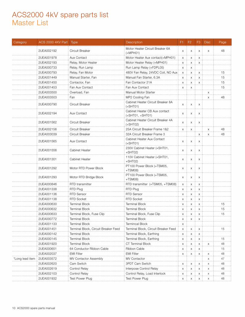
ACS2000 4kV spare parts listMaster List
2UEA002192 Circuit BreakerMotor Heater Circuit Breaker 6A (+MPH01)
x x x x 48
2UEA001978 Aux Contact Motor Heater Aux contact(+MPH01) x x x
2UEA002193 Relay, Motor Heater Motor Heater Relay (+MPH01) x x x
2UEA000733 Relay, Run Lamp Run Lamp Relay (+FDPL05) x x
2UEA000793 Relay, Fan Motor 480V Fan Relay, 24VDC Coil, NO Aux x x x 15
2UEA001449 Manual Starter, Fan Manual Fan Starter, 6.3A x x x 15
2UEA001450 Contactor, Fan Fan Contactor 21A x x x 15
2UEA001453 Fan Aux Contact Fan Aux Contact x x 15
2UEA003500 Overload, Fan Manual Motor Starter x
2UEA003503 Fan MP2 Cooling Fan x 48
2UEA000790 Circuit BreakerCabinet Heater Circuit Breaker 8A (+SHT01)
x x x
2UEA002194 Aux ContactCabinet Heater CB Aux contact (+SHT01, +SHT01)
x x x
2UEA001562 Circuit BreakerCabinet Heater Circuit Breaker 4A (+SHT02)
x x x
2UEA002156 Circuit Breaker 25A Circuit Breaker Frame 1&2 x x x 48
2UEA003039 Circuit Breaker 32A Circuit Breaker Frame 3 x x 48
2UEA001565 Aux ContactCabinet Heater Aux Contact (+SHT01)
x x x
2UEA001556 Cabinet Heater230V Cabinet Heater (+SHT01, +SHT02)
x x x
2UEA001301 Cabinet Heater110V Cabinet Heater (+SHT01, +SHT02)
x x x
2UEA001292 Motor RTD Power BlockPT100 Power Block (+TSM05, +TSM08)
x x x
2UEA001293 Motor RTD Bridge BlockPT100 Power Block (+TSM05, +TSM08)
x x x
2UEA000846 RTD transmitter RTD transmitter (+TSM05, +TSM08) x x x
2UEA001338 RTD Plug RTD Plug x x x
2UEA001136 RTD Sensor RTD Sensor x x x
2UEA001138 RTD Socket RTD Socket x x x
2UEA000630 Terminal Block Terminal Block x x x 15
2UEA000632 Terminal Block Terminal Block x x x 15
2UEA000633 Terminal Block, Fuse Clip Terminal Block, Fuse Clip x x x 15
2UEA000772 Terminal Block Terminal Block x x x
2UEA001133 Terminal Block Termincal Block x
2UEA001451 Terminal Block, Circuit Breaker Feed Terminal Block, Circuit Breaker Feed x x x 15
2UEA000142 Terminal Block Terminal Block, Earthing x x x
2UEA000145 Terminal Block Terminal Block, Earthing x x x 15
2UEA001920 Terminal Block CT Terminal Block x x x x 48
2UEA000651 64 Conductor Ribbon Cable Ribbon Cable x x x 15
2UEA002037 EMI Filter EMI Filter x x x x 48
*Long lead item 2UEA003572 MV Contactor Assembly MV Contactor x 47
2UEA002620 Cam Switch 3PDT Cam Switch x x x x 48
2UEA002619 Control Relay Interpose Control Relay x x x x 48
2UEA002103 Control Relay Control Relay, Load Interlock x x x x 48
2UEA001932 Test Power Plug Test Power Plug x x x x 48
Category ACS 2000 4KV Part Type Description F1 F2 F3 Disc Page

ACS2000 spare parts manual 11
ACS2000 4kV spare parts listMaster List
MiscellaneousMechanics
2UEA000463 Handle For Grounding Switch Grounding Switch x x x
3BHB021516R0001 Grounding Switch Grounding Switch x x x 21,25,37
2UEA001078 Pressure Switch Pressure Switch x x x
2UEA001051 Cooling Fan Cooling fan x x x 28
2UEA002898 Cooling Fan Removal Kit Cooling Fan Removal Kit Frame 1 x
2UEA003161 Cooling Fan Removal Kit Cooling Fan Removal Kit Frame 2 x
2UEA003163 Cooling Fan Removal Kit Cooling Fan Removal Kit Frame 3 x
2UEA001026 Filter Converter Door Filter x
2UEA001026 FilterIFU Section Door Filter (SN≥2124903744)
x
2UEA001042 FilterIFU Section Door Filter (SN<2124903744)
x
2UEA001704 Filter Converter Door Filter x
2UEA001694 Filter IFU Section Door Filter x x
2UEA002487 Filter Converter Door Filter x
2UEA003461 Filter Disconnect Cabinet Filter x 47
2UEA001135 Door Hinge Door Hinge (SN<2124903744) x
2UEA001629 Door Hinge Door HInge (SN≥2124903744) x x x 13
2UEA003089 Air Plenum Phase Module Plenum x
2UEA001770 Air Plenum Phase Module Plenum x 32
2UEA003189 Air Plenum Phase Module Plenum x 41
2UEA001362 Phase Module Exchange Tool Phase Module Exchange Tool x
2UEA002274 Phase Module Exchange Tool Phase Module Exchange Tool x x
2UEA002371 Phase Module Lift Hoist Phase Module Lift Hoist x x
2UEA002535 Hoist Frame Hoist Frame x
2UEA002151 Hoist Bracket Hoist Bracket x
2UEA003047 Phase Module Contact Phase Module Contact Receptacle x
2UEA003048 Phase Module Contact Phase Module Contact Receptacle x
2UEA003049 Phase Module Contact Phase Module Contact Receptacle x
2UEA003034 Door Lock AssemblyLow Voltage Controls Door Lock w/ Key
x x x
2UEA002174 Key Low Voltage Controls Door Key x x x x
2UEA003035 Door Lock Assembly Phase Module Door Lock w/ Key x x x
2UEA002152 LVD Door Lock LVD Door Lock x 45
2UEA002175 Key Phase Module Door Key x x x x
2UEA002207 MV Door Lock MV Door Lock x 45
Drive Options
2UEA000983 Modbus Module Modbus Module NMBA-01 (+FAMM0) x x x
2UEA001290 Controlnet Module Controlnet Module (+FAMAC) x x x
2UEA001065 Device Net Module Device Net Module (+FAMAD) x x x
2UEA001063 Ethernet Module Ethernet Module NETA-01 (+FAME0) x x x
2UEA001064 Ethernet Adaptor ModuleEthernet IP Adaptor Module (+FA-MAE)
x x x
2UEA001291 NPBA-12 Module Profibus NPBA-12 Module (+FAMP0) x x x
2UEA001067 Speed MeasurementSpeed Measurement NTAC-02 (+ENCS0)
x x x
3AUA0000040000 Drive Window Kit Drive Window and DDCS adaptor x x x
2UEA003060 Drive Monitor Kit Drive Monitor 3000 (+DMN01) x x x
Category ACS 2000 4KV Part Type Description F1 F2 F3 Disc Page
12 ACS2000 spare parts manual
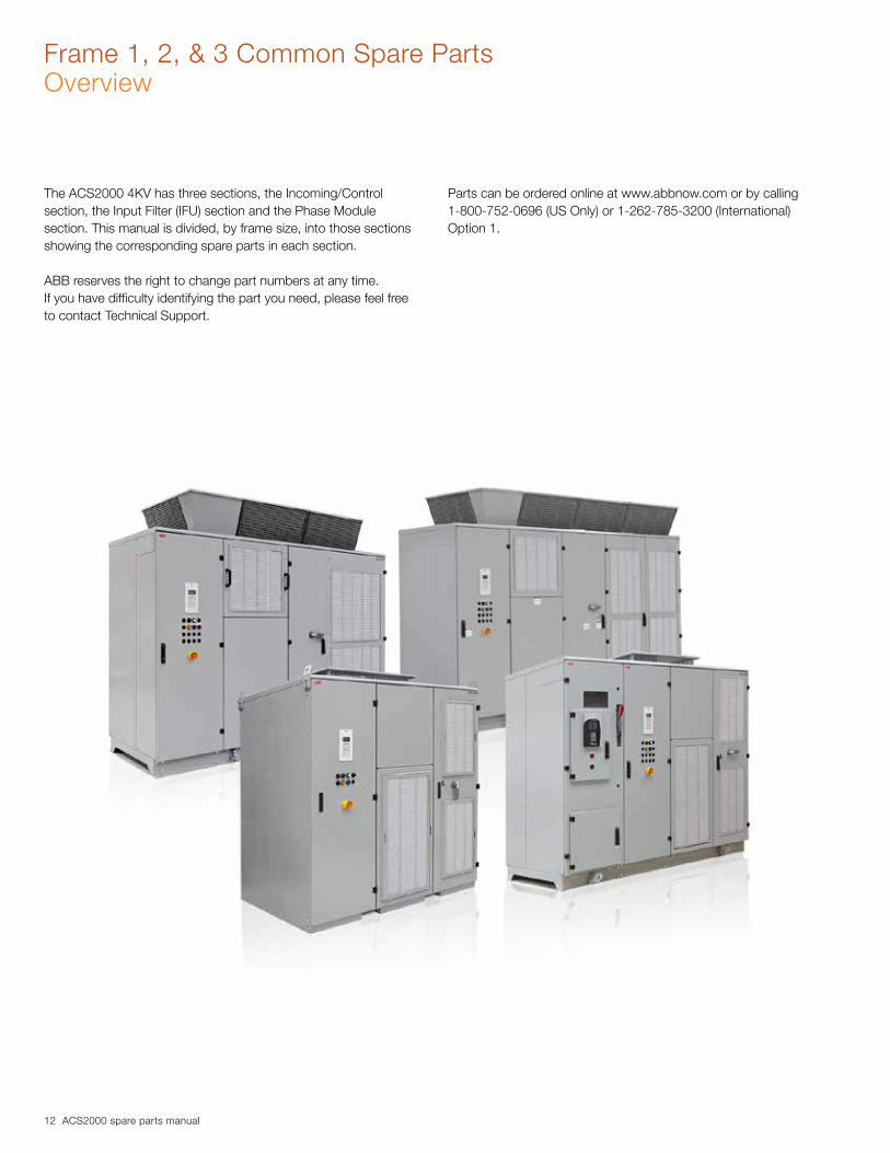
The ACS2000 4KV has three sections, the Incoming/Control section, the Input Filter (IFU) section and the Phase Module section. This manual is divided, by frame size, into those sections showing the corresponding spare parts in each section.
ABB reserves the right to change part numbers at any time.If you have difficulty identifying the part you need, please feel free to contact Technical Support.
Parts can be ordered online at www.abbnow.com or by calling 1-800-752-0696 (US Only) or 1-262-785-3200 (International) Option 1.
Frame 1, 2, & 3 Common Spare Parts Overview

ACS2000 spare parts manual 13
Frame 1, 2, & 3 Common Spare PartsIncoming/Control Section Front Door
Item Part number Cabinet Qty Description Notes
1.1 2UEA000987 1 CDP-312R Control Panel Equivalent to 68281059
1.2 3BHL000764P0001 1 Control Panel Interface NDPI-02 Equivalent to 58914444
1.3 2UEA000986 1 Keypad Frame Equivalent to 68228344
1.4 2UEA000570 1 CDP312 Connector Plug
1.5 2UEA000572 1 Y-Connector, RJ12
1.6 2UEA000950 1 Pushbutton Operator - White, 30MM
1.7 2UEA000958 2 Contact and lamp block with holder kit
1.8 2UEA000962 1 LED - White
1.9 2UEA000951 1 Pushbutton Operator - Green, 30MM
1.10 2UEA000963 1 LED-Green
1.11 2UEA000952 1 Operator, Yellow
1.12 2UEA000959 2 Lamp Block w/Holder
1.13 2UEA000964 1 LED-Yellow
1.14 2UEA000953 1 Operator, Blue
1.15 2UEA000965 1 LED-Blue
1.16 2UEA000131 1 Emergency Stop Protective Collar
1.17 2UEA000130 1 Emergency Stop Pushbutton
1.18 2UEA001312 1 Emergency Stop Contact Block
1.19 2UEA001135 10 Door Hinge (SN<2124903744)
1.19 2UEA001629 10 Door Hinge (SN≥2124903744)
1.20 2UEA003034 1 Door Lock with key
Picture 1: Front view of incoming section
1.3 1.1 1.2
1.51.4
1.7 1.8
1.6
1.10
1.9
1.7
1.18
1.161.17 1.19
1.14
1.151.12
1.11
1.131.12
1.20

14 ACS2000 spare parts manual
Incoming/Control SectionControl swing frame
Picture 2A: Swing frame - Front Picture 2B: Swing frame - Back
1.22
1.23
1.24
1.25
1.26
1.27
1.28
1.29
1.31 1.33
1.32
1.34
1.35
1.36
1.37
1.38
1.21
1.22
1.421.40
1.44
1.39 1.41
1.43
1.30

ACS2000 spare parts manual 15
Item Part number Cabinet Qty Description Notes
1.21 3BHE024577R0101 2 AMC 34 Control Board Equivalent to 68281059
1.22 3BHE024855R0101 2 INT-2 Board Equivalent to 58914444
1.23 2UEA000651 2 64 Conductor Ribbon Cable
1.24 2UEA000633 6 Terminal Block, Fuse Clip
1.25 2UEA000761 6 Fuse, 4A
1.26 2UEA000630 23 Terminal Block
1.27 2UEA000632 3 Terminal Block
1.28 2UEA000145 4 Terminal Block, Earthing
1.29 2UEA001336 1 Circuit Breaker, 2 Pole 10A 480V
1.30 2UEA000791 1 Circuit Breaker, 3 Pole 4A 480V
1.31 2UEA000793 1 480V Relay, 24VDC Coil, NO Aux Qty may differ based on options
1.32 2UEA000936 2 20A 3 Phase Buffer Module Qty may differ based on options
1.332UEA002224 2UEA002709
1Power Supply, 24VDC, 40A 480AC Power Supply, 24VDC, 120/240AC (+SPC01)
Part number is based on incoming control voltage utilized
1.34 2UEA001960 0 Battery, 24VDC, 12 Ah Optional Equipment
1.35 3BHB003041R0101 1 IOEC Control Module Qty may differ based on options
1.36 2UEA000843 6 IOEC Connector-3 Position
1.37 2UEA000845 3 IOEC Connector-10 Position
1.38 2UEA000861 2 IOEC Connector-7 Position
1.39 2UEA001449 1 Manual Starter Qty may differ based on options
1.40 2UEA001450 1 Contactor Qty may differ based on options
1.41 2UEA001451 1 Terminal Block, Circuit Breaker Feed Qty may differ based on options
1.42 2UEA001452 0 Aux. Block, 4 Pole Qty may differ based on options
1.43 2UEA001453 1 Aux. Contact. Manual Starter Qty may differ based on options
1.44 2UEA001961 0 UPS, DC, 24Vdc, 40A Qty may differ based on options
Incoming/Control Section

16 ACS2000 spare parts manual
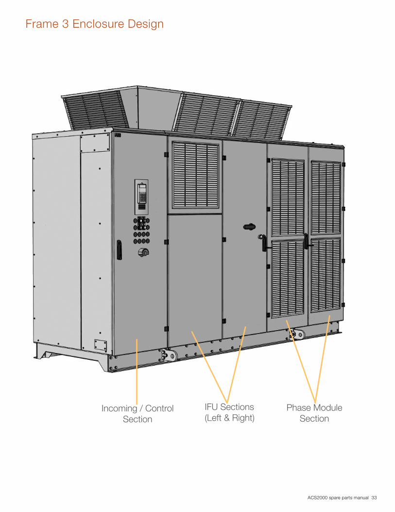
Frame 1 Enclosure Design
Incoming / Control Section
IFU Section
Phase Module Section

ACS2000 spare parts manual 17
Incoming/Control Section
Picture 3: View from back of incoming section
Item Part number Cabinet Qty Description Notes
1.1 2UEA000149 3 Surge Arrestor
1.2 2UEA001267 3 Fuse, 70 Amp 300-400 HP
1.2 2UEA001268 3 Fuse, 140 Amp 450-700HP
1.2 2UEA000093 3 Fuse, 200 Amp 800-1000 HP
1.2
1.1

18 ACS2000 spare parts manual
IFU SectionMiddle - Resistor box components
Picture 4B: Top of resistor box - Input filter capacitor assembly
2.9 2.7
2.1
2.4
2.2
2.3
2.11
2.8 2.6 2.5
2.10
Picture 4A: Resistor box assembly
ACS2000 spare parts manual 19
IFU SectionMiddle - Resistor box components
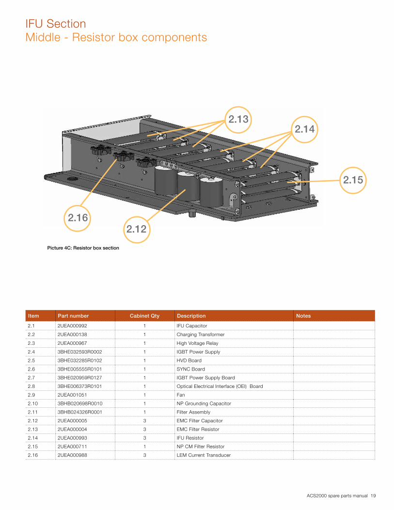
Item Part number Cabinet Qty Description Notes
2.1 2UEA000992 1 IFU Capacitor
2.2 2UEA000138 1 Charging Transformer
2.3 2UEA000967 1 High Voltage Relay
2.4 3BHE032593R0002 1 IGBT Power Supply
2.5 3BHE032285R0102 1 HVD Board
2.6 3BHE005555R0101 1 SYNC Board
2.7 3BHE020959R0127 1 IGBT Power Supply Board
2.8 3BHE006373R0101 1 Optical Electrical Interface (OEI) Board
2.9 2UEA001051 1 Fan
2.10 3BHB020698R0010 1 NP Grounding Capacitor
2.11 3BHB024326R0001 1 Filter Assembly
2.12 2UEA000005 3 EMC Filter Capacitor
2.13 2UEA000004 3 EMC Filter Resistor
2.14 2UEA000993 3 IFU Resistor
2.15 2UEA000711 1 NP CM Filter Resistor
2.16 2UEA000988 3 LEM Current Transducer
Picture 4C: Resistor box section
2.132.14
2.15
2.162.12

20 ACS2000 spare parts manual
Picture 5: Front view of inductor stack
Item Part number Cabinet Qty Description Notes
2.17 2UEA002918 1 Inductor Stack Kit
2.18 2UEA000886 1 EMC Filter Inductor (SN<2124903744)
For drives in this serial range the EMC Inductor is located above the inrestor, not on top of the Inductor Stack as shown above.
2.18 2UEA002220 1 EMC Filter Inductor (SN≥2124903744)
2.19 2UEA002349 2 Inrestor
IFU SectionBottom half
2.17
2.18
2.19
ACS2000 spare parts manual 21
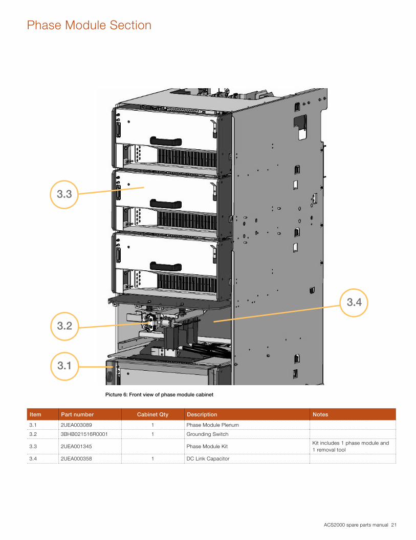
Phase Module Section
Item Part number Cabinet Qty Description Notes
3.1 2UEA003089 1 Phase Module Plenum
3.2 3BHB021516R0001 1 Grounding Switch
3.3 2UEA001345 Phase Module KitKit includes 1 phase module and 1 removal tool
3.4 2UEA000358 1 DC Link Capacitor
Picture 6: Front view of phase module cabinet
3.3
3.2
3.4
3.1

22 ACS2000 spare parts manual
Phase Module SectionNP Frame
Item Part number Cabinet Qty Description Notes
3.5 2UEA000893 2 DC Link Resistor
3.6 2UEA003051 1 Crowbar Stack Assembly
3.7 2UEA000360 4 Clamp Resistor
3.8 2UEA000357 4 Clamp Capacitor
3.9 2UEA000911 4 Clamp Diode
3.10 2UEA000883 4 Clamp Inductor
3.11 3BHE009017R0102 4Voltage Level Short Circuit Detection (VLSCD) Board
3.12 3BHE024747R0101 1 Crowbar Board
Picture 7A: Top Half of NP Frame
3.9
3.8
3.11
3.5
Picture 7B: Bottom Half of NP Frame
3.10
3.7
3.12
3.6

ACS2000 spare parts manual 23
Frame 2 Enclosure Design
Incoming / Control Section
IFU Sections(Left & Right)
Phase Module Section
24 ACS2000 spare parts manual
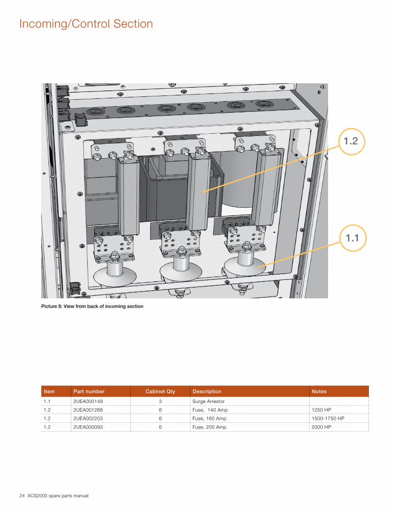
Incoming/Control Section
Item Part number Cabinet Qty Description Notes
1.1 2UEA000149 3 Surge Arrestor
1.2 2UEA001268 6 Fuse, 140 Amp 1250 HP
1.2 2UEA002203 6 Fuse, 160 Amp 1500-1750 HP
1.2 2UEA000093 6 Fuse, 200 Amp 2000 HP
1.1
1.2
Picture 8: View from back of incoming section

ACS2000 spare parts manual 25
IFU SectionRight Cabinet
Picture 9A : Right Cabinet Left Side
Item Part number Cabinet Qty Description Notes
2.1 2UEA001407 1 CM Filter Resistor
2.2 2UEA001456 3 Current Transducer
2.3 3BHB021516R0001 1 Grounding Switch
2.3
2.1
2.2

26 ACS2000 spare parts manual
IFU SectionRight Cabinet
Item Part number Cabinet Qty Description Notes
2.4 2UEA003063 1 Crowbar Stack Assembly
2.5 2UEA001406 1 DC Link Capacitor
2.6 3BHE024747R0101 1 Crowbar Board
2.7 2UEA001348 2 DC Link Resistor
2.8 2UEA003150 2 InrestorPlease see technical note on pg. 43 of this manual
2.9 3BHE032593R0002 1 IPS Power Supply
Picture 9B: Right Cabinet, Right Side
2.4
2.6
2.8
2.9
2.5
2.7

ACS2000 spare parts manual 27
IFU SectionFilter Assembly
Item Part number Cabinet Qty Description Notes
2.10 3BHB024326R0001 1 Filter Assembly
2.11 2UEA001352 1 IFU Capacitor
2.12 3BHB020698R0010 1 NP Grounding Capacitor
2.13 2UEA000967 1 High Voltage Relay
2.14 3BHE005555R0101 1 Sync Board
2.15 3BHE020959R0127 1 IGBT Power Supply Board
2.16 3BHE006373R0101 1 Optical Electrical Interface (OEI) Board
2.17 3BHE032285R0102 1 High Voltage Divider (HVD) Board
2.17
2.142.11
2.13
2.15
2.10
2.162.12
Picture 10: IFU Filter Assembly

28 ACS2000 spare parts manual
IFU SectionLeft Cabinet
Item Part number Cabinet Qty Description Notes
2.18 2UEA001352 1 IFU Capacitor
2.19 2UEA003159 1 Inductor Stack kit with Base
2.20 2UEA003160 1 EMC Filter Inductor
2.21 2UEA000138 1 Charging Transformer
2.22 2UEA001051 2-3 Cooling Fan
2.23 2UEA001404 3 EMC Filter Capacitor
2.23
2.20
2.22 2.18
2.21
Picture 11: Left IFU Cabinet
2.19

ACS2000 spare parts manual 29
IFU SectionResistor Assembly
Item Part number Cabinet Qty Description Notes
2.24 2UEA001350 3 IFU Resistor
2.25 2UEA001505 3 EMC Filter Resistor
2.25
2.24
Picture 12: Resistor Assembly - view from the top
30 ACS2000 spare parts manual
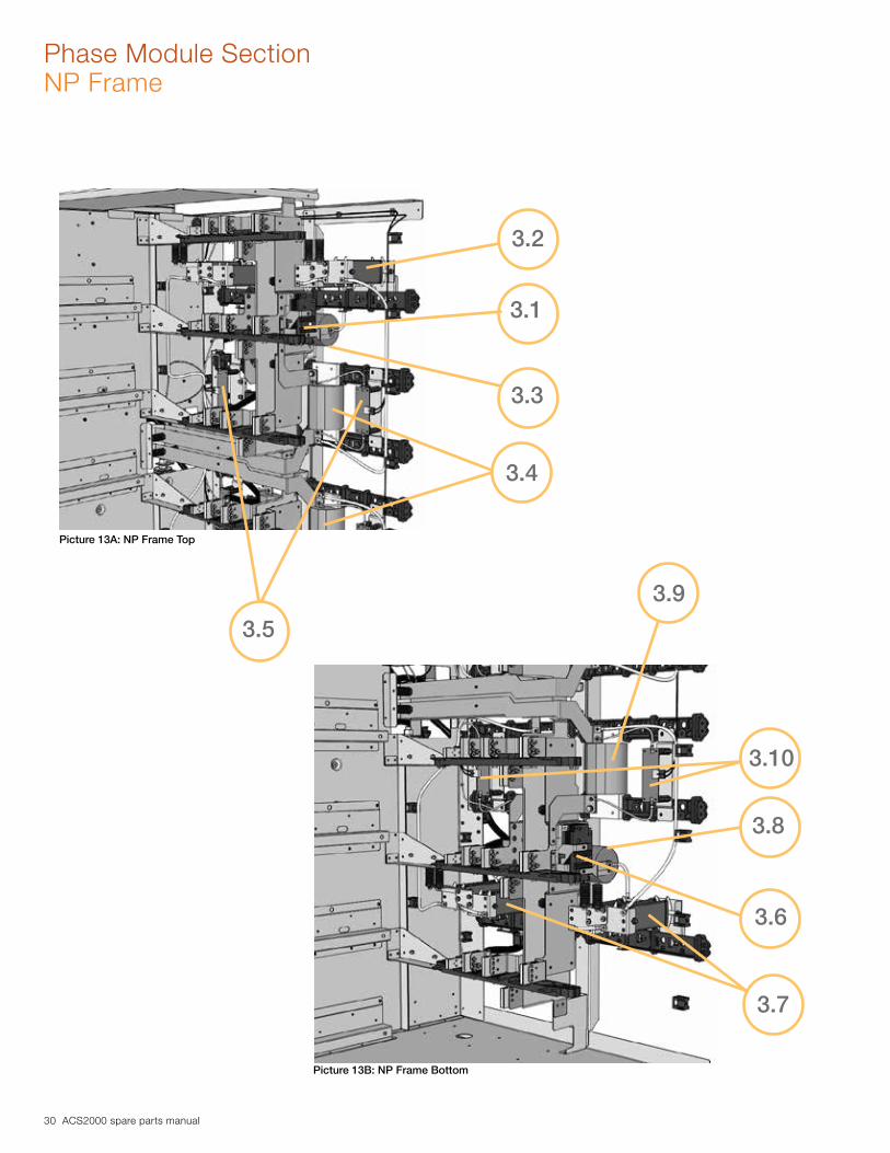
Phase Module SectionNP Frame
3.2
3.1
3.3
3.4
3.5
Picture 13A: NP Frame Top
Picture 13B: NP Frame Bottom
3.7
3.6
3.8
3.10
3.9

ACS2000 spare parts manual 31
Phase Module SectionNP Frame
Item Part number Cabinet Qty Description Notes
3.1 2UEA000911 8 Clamp Diode
3.2 2UEA000360 8 Clamp Resistor
3.3 2UEA001405 4 Clamp Capacitor
3.4 2UEA001403 4 Clamp Inductor
3.5 3BHE009017R0102 4Voltage Level Short Circuit Detection (VLSCD) Board
Item Part number Cabinet Qty Description Notes
3.6 2UEA000911 8 Clamp Diode
3.7 2UEA000360 8 Clamp Resistor
3.8 2UEA001405 4 Clamp Capacitor
3.9 2UEA001403 4 Clamp Inductor
3.10 3BHE009017R0102 4Voltage Level Short Circuit Detection (VLSCD) Board
NP Frame Top
NP Frame Bottom

32 ACS2000 spare parts manual
Phase Module SectionFront
Item Part number Cabinet Qty Description Notes
3.11 2UEA002570 Phase Module KitKit includes 1 phase module and 1 removal tool
3.12 2UEA001770 2 Phase Module Plenum
3.12
3.11
Picture 14: Front view of phase module cabinet
ACS2000 spare parts manual 33
Frame 3 Enclosure Design
Incoming / Control Section
IFU Sections(Left & Right)
Phase Module Section

34 ACS2000 spare parts manual
Frame 3Front View
Item Part number Cabinet Qty Description Notes
2.A 2UEA003165 1 Common Mode Inductor Stack IFU Section - Right Cabinet
2.B 2UEA003166 1 EMC Filter Inductor IFU Section - Right Cabinet
2.C 3BHE032593R0002 1 IGBT Power Supply IFU Section - Right Cabinet
2.D 2UEA002348 2 Inrestor IFU Section - Right Cabinet
2.E 2UEA001466 2 DC Link Capacitor IFU Section - Left Cabinet
3.A 2UEA003021 Phase Module Kit with removal tool Phase Module Section
2.D
2.A
2.B
2.C
3.A2.E
ACS2000 spare parts manual 35
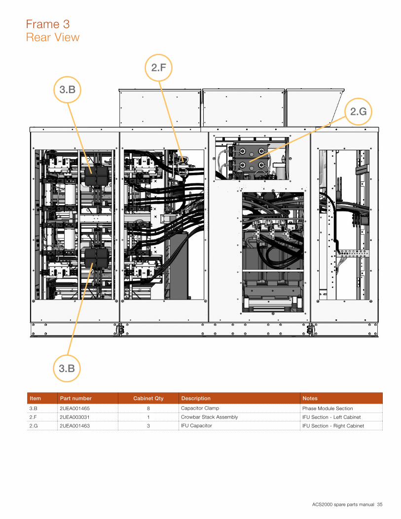
Frame 3Rear View
Item Part number Cabinet Qty Description Notes
3.B 2UEA001465 8 Capacitor Clamp Phase Module Section
2.F 2UEA003031 1 Crowbar Stack Assembly IFU Section - Left Cabinet
2.G 2UEA001463 3 IFU Capacitor IFU Section - Right Cabinet
3.B
2.G
2.F
3.B

36 ACS2000 spare parts manual
Incoming/Control Section
1.2
1.1
Item Part number Cabinet Qty Description Notes
1.1 2UEA000149 3 Surge Arrestor
1.2 2UEA001947 6 Fuse, 230 Amp 2250 - 3000 HP
Picture 15: View from back of incoming section

ACS2000 spare parts manual 37
IFU Section Right Cabinet - Front
Item Part number Cabinet Qty Description Notes
2.1 2UEA003165 1 Common Mode Inductor
2.2 3BHB021516R0001 1 Grounding Switch
2.3 2UEA003166 1 EMC Filter Inductor
2.4 2UEA001464 6 EMC Filter Capacitor
2.3
2.1
2.2
2.4
Picture 16: IFU section right cabinet view from front

38 ACS2000 spare parts manual
IFU Section Right Cabinet - Rear
Item Part number Cabinet Qty Description Notes
2.5 2UEA002111 3 Current Transducer
2.6 2UEA001470 2 DC Link Resistor
2.7 2UEA001463 3 IFU Capacitor
2.8 2UEA000138 1 Charging Transformer
2.9 2UEA003164 1 IFU Inductor Stack
2.5
2.9
2.8
2.7
2.6
Picture 17: IFU section right cabinet view from rear

ACS2000 spare parts manual 39
IFU Section Filter Assembly
Item Part number Cabinet Qty Description Notes
2.10 3BHB020698R0010 1 NP Grounding Capacitor
2.11 3BHB024326R0001 1 Filter Assembly
2.12 3BHE020959R0127 1 IGBT Power Supply Board
2.13 2UEA000967 1 High Voltage Relay
2.14 3BHE005555R0101 1 Sync Board
2.15 3BHE032285R0102 1 High Voltage Divider (HVD) Board
2.16 3BHE006373R0101 1 Optical Electrical Interface (OEI) Board
2.11
2.12
2.10
2.16
2.15
2.142.13
Picture 18: IFU Filter Assembly
40 ACS2000 spare parts manual
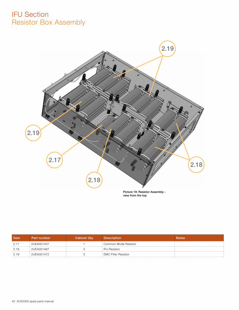
IFU SectionResistor Box Assembly
Item Part number Cabinet Qty Description Notes
2.17 2UEA001407 1 Common Mode Resistor
2.18 2UEA001467 3 IFU Resistor
2.19 2UEA001472 3 EMC Filter Resistor
2.17
2.19
2.18
2.18
2.19
Picture 19: Resistor Assembly - view from the top
ACS2000 spare parts manual 41
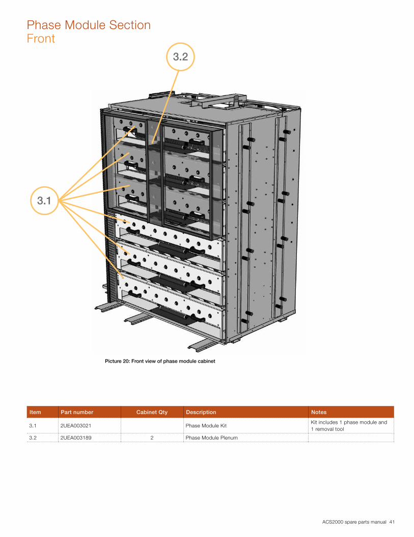
Phase Module SectionFront
Item Part number Cabinet Qty Description Notes
3.1 2UEA003021 Phase Module KitKit includes 1 phase module and 1 removal tool
3.2 2UEA003189 2 Phase Module Plenum
3.1
3.2
Picture 20: Front view of phase module cabinet

42 ACS2000 spare parts manual
Phase Module SectionNP Top Frame
Item Part number Cabinet Qty Description Notes
3.3 2UEA000911 12 Clamp Diode
3.4 2UEA002974 4 Clamp Inductor
3.5 3BHE009017R0102 4Voltage Level Short Circuit Detection (VLSCD) Board
3.6 2UEA001469 4 Clamp Resistor Assembly
3.5
3.3
3.4
3.6
Picture 21: NP Frame Top*Note: NP top and bottom of frame are identical
Front View - Clamp Diode

ACS2000 spare parts manual 43
Integral Disconnect Enclosure Section
Incoming / Control Section
IFU Section Phase Module Section
Integral Disconnect

44 ACS2000 spare parts manual
Integral Disconnect
1.111.10
1.5 1.6
1.9
1.1
1.8 1.7
1.2
1.11
1.3
1.11
1.10
1.4
1.7

ACS2000 spare parts manual 45
Integral Disconnect
Item Part number Cabinet Qty Description Notes
1.1 2UEA001919 1 Motor Management Relay
1.2 2UEA003092 1 Motor Management Relay
1.3 2UEA001894 3 Current Transducer
1.4 2UEA003040 3 Current Transducer
1.5 2UEA002665 1 LED, Green
1.6 2UEA001520 1 Operator, Green
1.7 2UEA000959 1 Lamp block w/ holder kit
1.8 2UEA002666 1 LED, Red
1.9 2UEA000956 1 Operator, Red
1.10 2UEA002152 2 LVD Lock
1.11 2UEA002207 3 MV Door Lock

46 ACS2000 spare parts manual
Integral Disconnect
1.18*
1.12
1.17*
1.19*
1.15*
1.14
1.13
1.16*

ACS2000 spare parts manual 47
Item Part number Cabinet Qty Description Notes
1.12 2UEA001267 3 Fuse, 80A
1.12 2UEA001268 3-6 Fuse, 140A
1.12 2UEA002203 6 Fuse, 160A
1.12 2UEA000093 3 Fuse, 200A
1.12 2UEA001947 3 Fuse, 230A
1.13 2UEA001899 1 Transformer
1.14 2UEA001900 1 Transformer
1.15 2UEA003503 1 Fan * Frame 3 component only
1.16 2UEA001449 1 Manual Starter, 6.3A * Frame 3 component only
1.17 2UEA001453 1 Aux. Contact * Frame 3 component only
1.18 2UEA002193 1 Contactor, 4 Pole, 21A * Frame 3 component only
1.19 2UEA003461 1 Filter * Frame 3 component only
1.20 2UEA002431 3 Fuses
1.21 2UEA002611 1 Transformer
1.22 2UEA003571 1 Isolation SwitchLong lead item: Consult factory for availability
1.23 2UEA003572 1 MV Contactor AssemblyLong lead item: Consult factory for availability
1.20
1.21
Close up view of transformer section
Integral Disconnect
1.23
1.22
48 ACS2000 spare parts manual
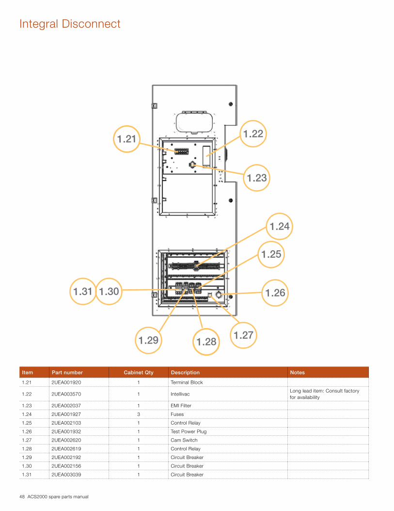
Integral Disconnect
Item Part number Cabinet Qty Description Notes
1.21 2UEA001920 1 Terminal Block
1.22 2UEA003570 1 IntellivacLong lead item: Consult factory for availability
1.23 2UEA002037 1 EMI Filter
1.24 2UEA001927 3 Fuses
1.25 2UEA002103 1 Control Relay
1.26 2UEA001932 1 Test Power Plug
1.27 2UEA002620 1 Cam Switch
1.28 2UEA002619 1 Control Relay
1.29 2UEA002192 1 Circuit Breaker
1.30 2UEA002156 1 Circuit Breaker
1.31 2UEA003039 1 Circuit Breaker
1.281.27
1.26
1.25
1.24
1.23
1.22
1.31 1.30
1.21
1.29

ACS2000 spare parts manual 49
Technical Notes
Note 1 - Frame 2: Replacement of inrestorsABB part number 2UEA003150 has replaced part number 3BHB024327R0001. This has also changed the inrestor configuration from a quantity four (4) inrestors to a quantity of two (2). Please note: If your drive currently utilizes part 3BHB024327R0001 and one of the inrestors fails, all (4) inrestors will need to be removed and replaced with two (2) part number 2UEA003150 inrestors.
Note 2 - Frame 3: Clamp inductors2UEA003213 is the new ABB part number for the clamp inductors used in all Frame 3 units going forward.
EXCEPTION: ABB part number 2UEA002974 will be used in units registered with any of the following serial numbers: 2131402054, 2131400989, 2131703324, 2131800104, 2132001102, 2132100102, 2132202416, 2132303473, 2132400343, 2132503681, 2133001095, 2133104388, 2133301488, 2134902217, 2140603274, 2140604672.

50 ACS2000 spare parts manual
Notes:

ACS2000 spare parts manual 51
Notes:
Cop
yrig
ht 2
014
AB
B.
All
right
s re
serv
ed.
Sp
ecifi
catio
ns s
ubje
ct t
o ch
ange
with
out
notic
e.
2UE
B00
0131
R
EV
DABB Inc.Medium Voltage Drives16250 W. Glendale DriveNew Berlin, WI 53151Tel: 800-752-0696Fax: 262-648-2072E-Mail: [email protected]
www.abb.us/drives
Contact us