abbreviations used in this manual - all-trans.by · pdf fileinstructions concerning these...
TRANSCRIPT

ABBREVIATIONS USED IN THIS MANUALA/T ATM Automatic TransmissionATF Automatic Transmission FluidB1 Second Coast BrakeB2 Second BrakeB3 First and Reverse BrakeB4 Underdrive BrakeC1 Forward ClutchC2 Direct ClutchC3 Underdrive ClutchD DiscEx. ExceptF FlangeF1 No. 1 One-way ClutchF2 No. 2 One-way ClutchF3 Underdrive One-way ClutchMP MultipurposeO/D OverdriveP PlateSSM Special Service MaterialsSST Special Service ToolsSTD StandardT/C Torque ConverterT/F TransferU/D Underdrivew/ with4WD Four Wheel Drive
IN-6-INTRODUCTION Abbreviations Used in This ManualW
WW.ALL-TR
ANS.BY

Differential
A240L
DESCRIPTIONGeneral
A240L, A241E, A243L
The A240L, A241E and A243L automatic transaxles are 4-speed transaxles with a lock-up mechanismdeveloped exclusively for use with a transversely-mounted engine.The A241E automatic transaxle is an Electronically Controlled Transaxle (hereafter called ECT).These automatic transaxles have the following features.� The “Super-Flow” torque converter is used to improve the transmission efficiency.� When shifting the transmission, the engine torque is controlled and the clutch hydraulic
pressure in the transmission is electronically controlled to reduce transmission shift shock.(A241E)
� Transaxle control ECU has been integrated with the Engine ECU. (A241E)These automatic transaxle are mainly composed of the torque converter with lock-up clutch, 4-speedplanetary gear unit, the hydraulic control system and the electronic control system.
To minimize the possibility of incorrect operation of the automatic transaxle, a shift lock mechanism hasalso been added.
Torque Converter,4-Speed Gear Unitand Hydraulic Control System
AT4118
AX-2-AUTOMATIC TRANSAXLE DescriptionW
WW.ALL-TR
ANS.BY

AT5715AT5716
A241E
A243L
-AUTOMATIC TRANSAXLE DescriptionAX-3W
WW.ALL-TR
ANS.BY

Transfer
Center Differential
Torque Converter,4-Speed Gear Unit,and Hydraulic Control System
A241H
The A241H automatic transaxle is a 4-speed automatic transaxle developed for full-time 4WD use.Its construction is that of the favorably received A240L automatic transaxle.
In addition, a center differential control clutch, which operates in response to driving conditions, has beenincorporated.
The center differential control clutch controls excessive differences in the rotation rates of the front andrear wheels to provide the most suitable driving conditions.
NOTICE: Special handling methods are necessary for full-time 4WD vehicles during inspection andmaintenance. Instructions concerning these handling methods are given on Corolla Repair Manual(Pub. No. RM252U) on page IN-8.
A241H
Front Differential
Center DifferentialControl Clutch
AT4877
AX-4-AUTOMATIC TRANSAXLE DescriptionW
WW.ALL-TR
ANS.BY

Type of Transaxle A240L A243L A241E A241H
Type of Engine 4A-FE 4A-FE 5S-FE 4A-FE
Torque ConverterStall Torque Ratio 2.3 : 1 2.5 : 1 2.0 : 1 2.3 : 1
Lock-Up Mechanism Equipped ← ← ←
Gear Ratio
1st Gear 3.643 4.005 3.643 ←
2nd Gear 2.008 2.208 2.008 ←
3rd Gear 1.296 1.425 1.296 ←
O/D Gear 0.892 0.981 0.892 ←
Reverse Gear 2.977 3.272 2.977 ←
Number of Discand Plates(Disc/Plate)
C1 Forward Clutch 4/4 ← ← ←
C2 Direct Clutch 2/3 2/3 3/3 2/3
C3 Underdrive clutch 3/3 3/3 3/5 3/3
B2 2nd Brake 3/3 ← ← ←
B3 1st and Reverse Brake 6/5 ← ← ←
B4 Underdrive Brake 3/3 ← ← ←
B1 Band Width mm (in.) 25 (0.98) ← ← ←
ATF
TypeATFDEXRON�II ← ←
ATF Type Tor equivalent
Capacityliter(US. qts, Imp. qts)
7.2(7.6, 6.3)
7.7(8.1, 6.8)
8.0(8.5, 7.0)
8.2(8.7, 7.2)
Transfer Oil
Type
Transaxle OilE50, API GL5,SAE 75W-90 orequivalent
Capacityliter(US. qts, Imp. qts)
0.8(0.8, 0.7)
General Specifications
-AUTOMATIC TRANSAXLE DescriptionAX-5W
WW.ALL-TR
ANS.BY

AT8498
U/D Clutch (C3)
One-W ayClutch (F1)
Front PlanetaryGear Unit
2nd Coast Brake (B1)
Forward Clutch (C1)
U/D Planetary Gear Unit
One-W ay Clutch (F2)
Range (i.e.,)Shift LeverPosition Gear
No. 1SolenoidValve*1
No. 2SolenoidValve*1 C1 C2 C3 B1 B2 B3 B4 F1 F2 F2
P Park ON OFF �
R Reverse ON OFF � � �
N Neutral ON OFF �
D
1st ON OFF � � � �
2nd ON ON � � � � �
3rd OFF ON � � � � �
O/D OFF OFF � � � �
2
1st ON OFF � � � �
2nd ON ON � � � � � �
3rd*2 OFF ON � � � � �
L1st ON OFF � � � � �
2nd*2 ON ON � � � � � �
*1: A241E only �: Operating*2: Down-Shift only in the the 3rd gear for the 2 range and 2nd gear for the L-range - no up-shift
Direct Clutch (C2)
OPERATIONMechanical Operation
OPERATING CONDITIONS
2nd Brake (B2)
1st & Reverse Brake (B3)
Rear PlanetaryGear Unit
U/D Brake (B4)
U/D One-Way Clutch (F3)
AX-6-AUTOMATIC TRANSAXLE OperationW
WW.ALL-TR
ANS.BY

Component Function
C1 Forward Clutch Connects input shaft and front planetary ring gear.
C2 Direct Clutch Connects input shaft and front & rear planetary sun gear.
C3 U/D Clutch Connects underdrive sun gear and underdrive planetary carrier.
B1 2nd Coast Brake Prevents front & rear planetary sun gear from turning either clockwise orcounterclockwise.
B2 2nd Brake Prevents outer race of F1 from turning either clockwise or counterclockwisethus preventing the front & rear planetary sun gear from turning counterclockwise.
B3 1st & Reverse Brake Prevents rear planetary carrier from turning either clockwise or counterclockwise.
B4 U/D Brake Prevents underdrive sun gear from turning either clockwise or counterclock-wise.
F1 No. 1 One-Way Clutch When B2 is operating, this clutch prevents the front & rear planetarysun gear from turning counterclockwise.
F2 No. 2 One-Way Clutch Prevents rear planetary carrier from turning counterclockwise.
F3 U/D One-Way Clutch Prevents underdrive planetary sun gear from turning clockwise.
Planetary GearsThese gears change the route through which driving force is transmitted inaccordance with the operation of each clutch and brake in order to increaseor reduce the input and output speed.
Counter Shaft
Input Shaft
Front PlanetaryGear Unit
U/D Planetary Gear Unit
FUNCTION OF COMPONENTS
Front & Rear Sun Gear
Rear PlanetaryGear Unit
Intermediate Shaft
Ring Gear
AT2690
-AUTOMATIC TRANSAXLE OperationAX-7W
WW.ALL-TR
ANS.BY

AT3216
D or 2 Range 1st Gear
AT3220
AT3217
D Range 2nd Gear
AT3221
AT3218
D Range 3rd Gear
AT3222
D Range O/D
FUNCTION OF COMPONENTS (Cont’d)
The conditions of operation for each gear position are shown on the following illustration:
2 Range 2nd Gear
L Range 1st Gear
R Range Reverse Gear
AT3219
AX-8-AUTOMATIC TRANSAXLE OperationW
WW.ALL-TR
ANS.BY

HYDRAULIC CONTROL SYSTEM
VALVE BODY
Hydraulic Control SystemThe hydraulic control system is composed of the oil pump, the valve body, the solenoid valves, the accu-mulators, the clutches and brakes, and the governor valve as well as the fluid passages which connectall of these components.
Based on the hydraulic pressure created by the oil pump, the hydraulic control system governs the hy-draulic pressure acting on the torque converter, clutches and brakes in accordance with the vehicle driv-ing conditions.
The governor valve produces hydraulic pressure in response to vehicle speed. Governor pressure in-creases as vehicle speed increases. (A240L and A243L)
There are three solenoid valves on the valve body of the A241E automatic transaxle.
The No. 1 and No. 2 solenoid valves are turned on and off by signals form the ECU to operate the shiftvalves and change the gear shift position.
The No. 3 solenoid valve is operated by signals from the ECU to the engage or disengage the lock-upclutch of the torque converter.
The valve body of the A240L and A243L automatic transaxle has one solenoid valve, which is for over-drive control.
A241E
OIL PUMP Hydr. pressure control
Fluid passage switching Planetary gear unitCLUTCHES & BRAKES
Torque converterThrottle Cable
SOLENOID VALVESECU
A240L, A243L and A241H
HYDRAULIC CONTROL SYSTEM
VALVE BODY
Governor ValveOIL PUMP Hydr. pressure control
CLUTCHES & BRAKESFluid passage switching Planetary gear unit
Torque converterThrottle Cable
O/D Main Switch SOLENOID VALVES
-AUTOMATIC TRANSAXLE OperationAX-9W
WW.ALL-TR
ANS.BY

DiagnosticCode Display
Transaxle
� Engine RPM Sensor� Crankshaft Angle Signal
� Neutral Start Signal� Shift Lever Position Signal
� Idling Signal� Throttle Position Signal
A241E Electronic Control System
GENERAL
The electronic control system for the A241E automatic transmission provides extremely precise controlof the gear shift timing and lock-up timing in response to driving conditions as sensed by various sen-sors located throughout the vehicle and in response to the engine’s running condition.
At the same time, the ECU control reduces vehicle squat when the vehicle starts out and gear shiftshock. The electronic control system is also equipped with a self diagnosis system which diagnoses mal-functions of electronically controlled components and warns the driver, and a fail-safe system whichmakes it possible for the vehicle to continue functioning when a malfunction occurs.
CONSTRUCTION
The electronic control system can be broadly divided into three groups; the sensors, ECU and actuators.
SENSORS Engine & ECT ECU ACTUATOR
ESAIDL Engine
IgniterVTA
Throttle Position Sensor
Ignition CoilTHW IGtWater Temperature Sensor
Ignition TimingControl
DistributorIGf
Spark PlugsNeG1, G-
Distributor
SPDNo. 1 Speed Sensor S1 No. 1 Solenoid
ValveSP2
No. 2 Speed SensorControl ofShift Timing
PNo. 2 SolenoidValveS2Pattern Select Switch
SL Lock-Up SolenoidValve
Control ofLock-Up TimingNeutral Start Switch
NSW
2, L
OD2 O/D OFFIndicator Light
Self-DiagnosticSystem
OD2O/D Main Switch
Back-Up SystemSTP
Stop Light Switch
OD1Cruise Control ECU
+BBattery
AX-10-AUTOMATIC TRANSAXLE OperationW
WW.ALL-TR
ANS.BY
AT7901 AT7902AT7904 AT7903
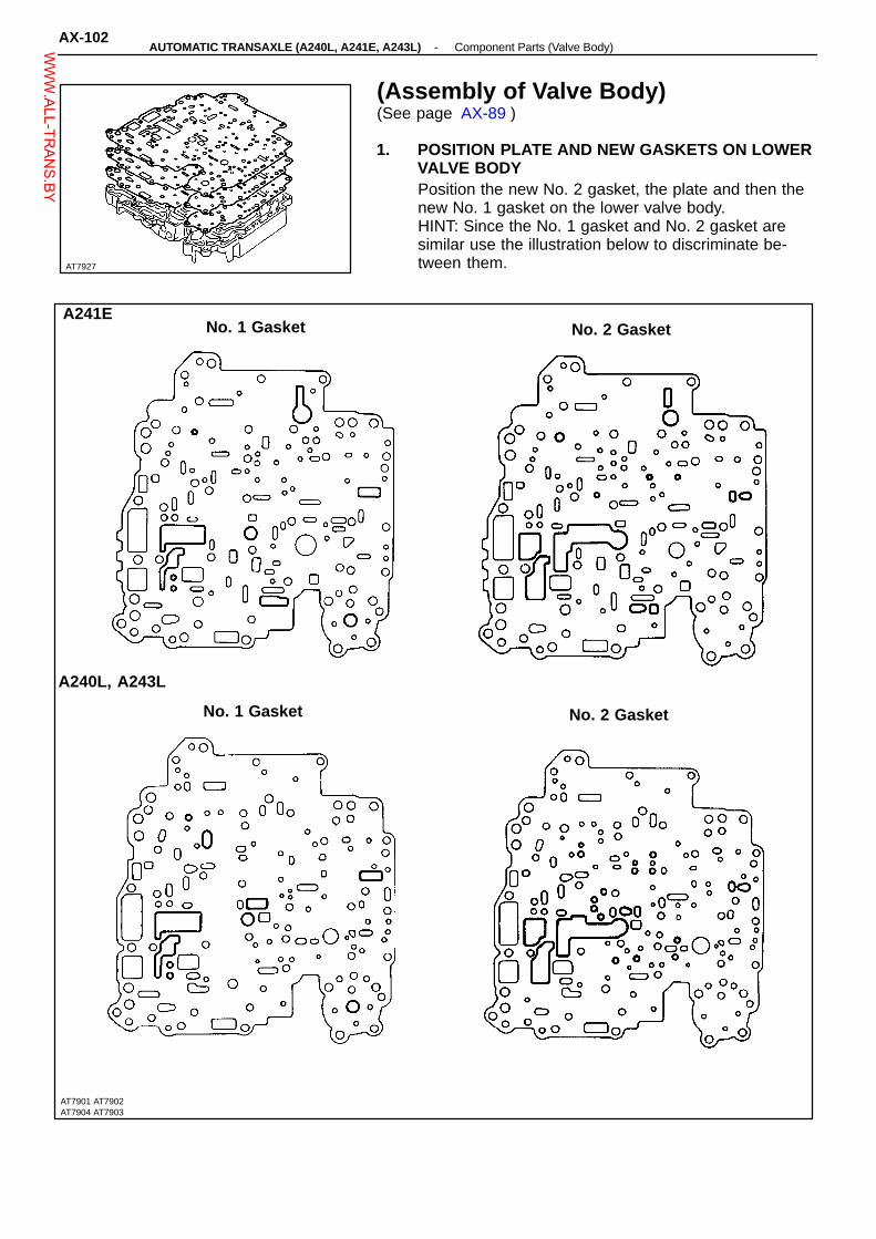
No. 1 Gasket
No. 2 GasketA241E
AT7927
(Assembly of Valve Body)(See page AX-89 )
1. POSITION PLATE AND NEW GASKETS ON LOWERVALVE BODYPosition the new No. 2 gasket, the plate and then thenew No. 1 gasket on the lower valve body.HINT: Since the No. 1 gasket and No. 2 gasket aresimilar use the illustration below to discriminate be-tween them.
No. 1 Gasket
A240L, A243L
No. 2 Gasket
AX-102-AUTOMATIC TRANSAXLE (A240L, A241E, A243L) Component Parts (Valve Body)W
WW.ALL-TR
ANS.BY

AT3055
A240L, A243L
AT2588
A241E
AT3048
A240L, A243L
AT3047
Plate
A243L
AT7983
2. PLACE LOWER VALVE BODY WITH PLATE ANDGASKETS ON UPPER VALVE BODYHINT: Hold the lower valve body, gaskets and plate se-curely so they do not separate.Align each bolt hole in the valve bodies with the gasketsand plate.
3. INSTALL AND FINGER TIGHTEN BOLTS IN LOWERVALVE BODY TO SECURE UPPER VALVE BODYInstall and finger tighten the five bolts. (A240L, A243L).HINT: Each bolt length (mm) is indicated in the figure.
Install: and finger tighten the nine bolts. (A241E)HINT: Each bolt length (mm) is indicated in the figure.
Strainer 4. INSTALL LOWER VALVE BODY COVER(a) Install the strainer. (A240L, A243L Only)
(b) Position a new gasket and plate and then anoth-er new gasket.
Gasket
Gasket
-AUTOMATIC TRANSAXLE (A240L, A241E, A243L) Component Parts (Valve Body)AX-103W
WW.ALL-TR
ANS.BY

AT3059
A240L, A243
AT8032
Gasket
Gasket
A240LA243L
AT2546
A241E
AT3058
AT3046
A241E
Plate
(c) Position the lower valve body cover.
(d) Install and finger tighten the seventeen bolts.(A240L, A243L)
HINT: Each bolt length (mm) is indicated in the figure.
5. INSTALL AND FINGER TIGHTEN BOLTS IN UPPERVALVE BODYInstall and finger tighten the eight bolts.HINT: Each bolt length (mm) is indicated in the figure.
6. TIGHTEN BOLTS OF UPPER AND LOWER VALVEBODIES(a) Tighten the twenty-two bolts in the lower valve
body.(A240L, A243L)
Torque: 6.4 N-m (65 kgf-cm, 56 in.-lbf)
(e) Install and finger tighten the ten bolts.(A241E)
HINT: Each bolt length (mm) is indicated in the figure.
AX-104-AUTOMATIC TRANSAXLE (A240L, A241E, A243L) Component Parts (Valve Body)W
WW.ALL-TR
ANS.BY

AT3058
AT7793
AT3138
A241E
AT5724
AT5725
(b) Tighten the nineteen bolts in the lower valve body.(A241E)
Torque: 6.4 N-m (65 kgf-cm, 56 in.-lbf)
A241E
(c) Tighten the eight bolts in the upper valve body.Torque: 6.4 N-m (65 kgf-cm, 56 in.-lbf)
7. INSTALL SOLENOID(a) Install the new O-rings on the each solenoids.
(b) Install the solenoids.HINT: Each bolt length (mm) is indicated in the figure.Torque: 6.4 N-m (kgf-cm, 56 in.-lbf)
A240L,A243L
Torque: A 6.4 N-m (65 kgf-cm, 56 in.-lbf)B 10 N-m (100 kgf-cm, 7 ft-lbf)
-AUTOMATIC TRANSAXLE (A240L, A241E, A243L) Component Parts (Valve Body)AX-105W
WW.ALL-TR
ANS.BY
AT8013
: Specified torque
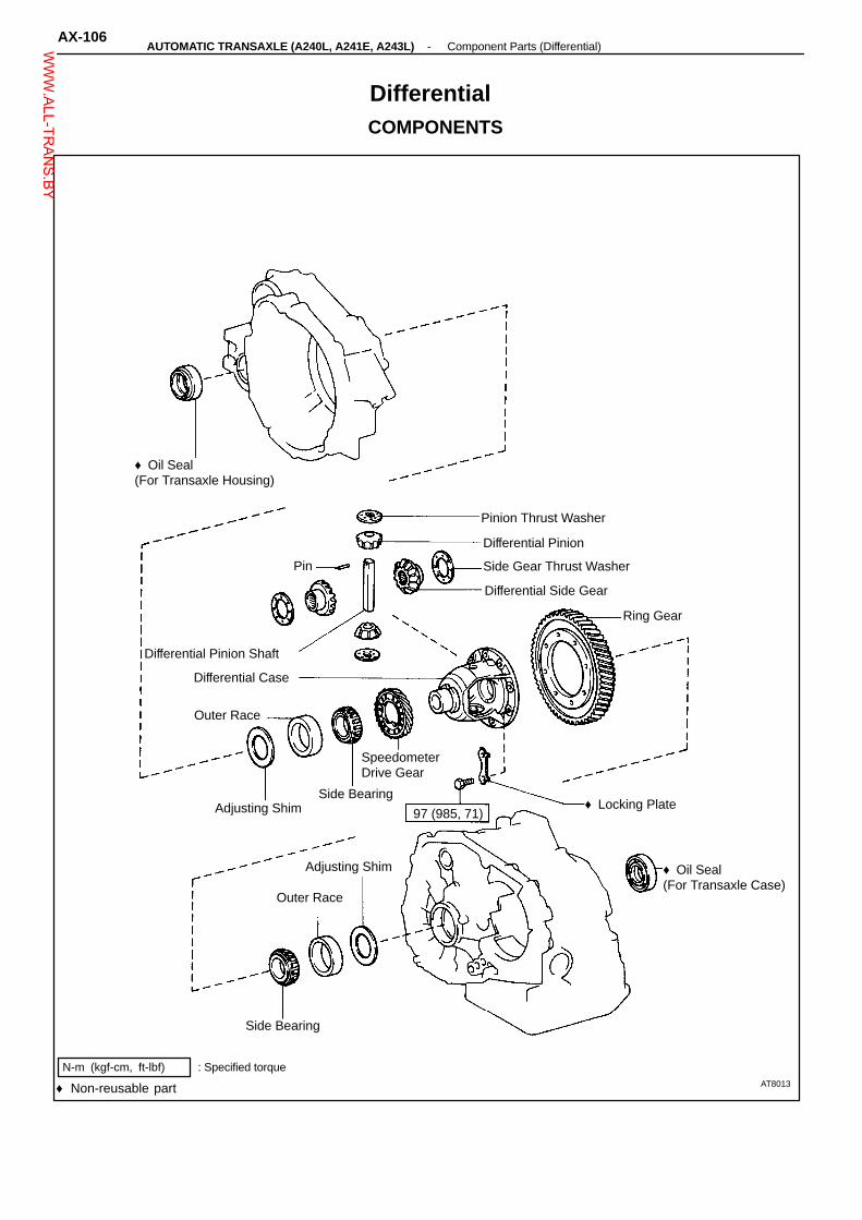
Outer Race
97 (985, 71)Adjusting Shim
Outer Race
Ring Gear
Side Gear Thrust Washer
Differential Pinion
♦ Oil Seal(For Transaxle Housing)
Differential Case
Adjusting Shim
N-m (kgf-cm, ft-lbf)
SpeedometerDrive Gear
DifferentialCOMPONENTS
Pinion Thrust Washer
Pin
Differential Side Gear
Differential Pinion Shaft
Side Bearing♦ Locking Plate
♦ Oil Seal(For Transaxle Case)
Side Bearing
♦ Non-reusable part
AX-106-AUTOMATIC TRANSAXLE (A240L, A241E, A243L) Component Parts (Differential)W
WW.ALL-TR
ANS.BY

TA0016
AT8087
AT7984
AT8062
AT5731
DISASSEMBLY OF DIFFERENTIAL
1. REMOVE RING GEAR(a) Place the matchmarks on the ring gear and differ-
ential case.
Matchmarks
(b) Loosen the staked part of the locking plate.
(c) Remove the eight bolts and four locking plates.
(d) Using a plastic hammer, tap on the ring gear toremove it from the case.
2. REMOVE SIDE BEARINGS FROM DIFFERENTIALCASE(a) Setting SST to the cut-out portion on the
speedometer drive gear, remove the bearing fromthe differential case.
SST 09502-10012(b) Remove the speedometer drive gear.
SST
-AUTOMATIC TRANSAXLE (A240L, A241E, A243L) Component Parts (Differential)AX-107W
WW.ALL-TR
ANS.BY

AT8061
AT8078
AT8059
AT7923
SideGear
Pinion
AT2980
(c) Setting SST to the cut-out portion on the differen-tial case, remove the bearing.
SST 09502-10012
SST
3. DISASSEMBLY DIFFERENTIAL CASE(a) Drive out the pinion shaft lock pin from the ring
gear side.
(b) Remove the pinion shaft from the case.Pinion Shaft
(c) Remove the two pinions, two side gears and fourthrust washers.
Thrust Washer
4. REMOVE OIL SEAL OF TRANSAXLE HOUSINGUsing a screwdriver, remove the oil seal.
AX-108-AUTOMATIC TRANSAXLE (A240L, A241E, A243L) Component Parts (Differential)W
WW.ALL-TR
ANS.BY

AT8486
AT8479
AT8002
AT8003
AT8487
5. REMOVE SIDE BEARING OUTER RACE OF TRANS-AXLE HOUSINGUsing SST and a hammer, drive out the outer race andshim.SST 09350-32014 (09351-32090)SST
6. REMOVE OIL SEAL OF TRANSAXLE CASEUsing a screwdriver, remove the oil seal.
7. REMOVE SIDE BEARING OUTER RACE OF TRANS-AXLE CASEUsing SST and a hammer, drive out the outer race andadjusting shim.SST 09350-32014 (09351-32130, 09351-32150)
SST
ASSEMBLY OF DIFFERENTIAL
1. INSTALL SIDE BEARING OUTER RACE OF TRANS-AXLE HOUSING(a) Place the shim onto the transaxle housing.
(b) Using SST and press, press a new outer raceinto the transaxle housing.
SST 09350-32014 (09351-32111, 09351-32130)
2. INSTALL SIDE BEARING OUTER RACE OF TRANS-AXLE CASE(a) Place the adjusting shim onto the transaxle case.
(b) Using SST and press, press a new outer raceinto the transaxle case.
SST 09350-32014 (09351-32111, 09351-32130)
-AUTOMATIC TRANSAXLE (A240L, A241E, A243L) Component Parts (Differential)AX-109W
WW.ALL-TR
ANS.BY

AT2980
AT8058
AT2981
mm (in.) mm (in.)
0.95 (0.0374)
1.00 (0.0394)
1.05 (0.0413)
1.10 (0.0433)
1.15 (0.0453)
1.20 (0.0472)
AT8497
3. ASSEMBLY DIFFERENTIAL CASE(a) Install the thrust washers to the side gears.
(b) Install the side gears with thrust washers, piniongears pinion thrust washers into the differentialcase.
(c) Install the pinion shaft so as to align the lock pinholes on the pinion shaft and differential case.
4. CHECK SIDE GEAR BACKLASH(a) Measure the side gear backlash while holding one
pinion gear toward the case.Standard backlash: 0.05 - 0.20 mm
(0.0020 - 0.0079 in.)If the backlash is out of specification, install the correctthrust washer to the side gear.(b) Referring to the table below, select thrust washers
which will ensure that the backlash is within speci-fication. Try to select washers of the same size ofboth sides.
Thrust washer thicknessesThicknessThickness
If the backlash is not within specification, install a thrustwasher of a different thickness.
AX-1 10-AUTOMATIC TRANSAXLE (A240L, A241E, A243L) Component Parts (Differential)W
WW.ALL-TR
ANS.BY

AT8093
AT8075
AT2982
AT8044
AT5833
5. INSTALL LOCK PIN(a) Using a hammer and punch, drive the lock pin
through the case and hole in the pinion shaft.
(b) Stake the differential case.
6. INSTALL SIDE BEARINGS TO DIFFERENTIAL CASE(a) Using SST and press, press the side bearing into
the differential case.SST 09710-30030 (09710-03160)
(b) Install the speedometer drive gear to the differen-tial case.
(c) Using SST and press, press the side bearing intothe differential case.
SST 09350-32014 (09351-32090, 09351-32120)
-AUTOMATIC TRANSAXLE (A240L, A241E, A243L) Component Parts (Differential)AX-1 11W
WW.ALL-TR
ANS.BY

AT8484
AT8485
AT5831
mm (in.)
2.00 (0.0787) 2.20 (0.0866) 2.40 (0.0945) 2.60 (0.1024) 2.80 (0.1102)
2.05 (0.0807) 2.25 (0.0886) 2.45 (0.0965) 2.65 (0.1043) 2.85 (0.1122)
2.10 (0.0827) 2.30 (0.0906) 2.50 (0.0984) 2.70 (0.1063) 2.90 (0.1142)
2.15 (0.0846) 2.35 (0.0925) 2.55 (0.1004) 2.75 (0.1083)
AT7886
SST
7. ADJUST SIDE BEARING PRELOAD(a) Remove any packing material and be careful not
to get oil on the contacting surfaces of the trans-axle housing or transmission case.
SealPacking
(b) Install the differential to the transaxle case.
(c) Install the transaxle housing to the transaxle case.
(d) Install and tighten the bolts.Torque: 29 N-m (300 kgf-cm, 22 ft-lbf)HINT: Each bolt length (mm) is indicated in the illustra-tion.
(e) Using SST, rotate the differential in both directionsto snug the bearing down.
SST 09563-3201 1(f) Using SST and a torque meter, measure the pre-
load of the side bearing.SST 09564-3201 1
Preload (at starting):New bearing 0.8-1.4 N-m
(8-14 kgf-cm, 6.9-12.2 in.-lbf)Used bearing 0.4-0.7 N-m
(4-7 kgf-cm, 3.5-6.1 in.-lbf)If the preload is not within specification, remove the differ-ential from the transaxle case. Re-select the transaxlecase side adjusting shim.
Thickness
HINT: The preload will change about 0.3 - 0.4 N-m (3 -4 kgf-cm, 2.6 - 3.5 in.-lbf) with each shim thickness.
AX-1 12-AUTOMATIC TRANSAXLE (A240L, A241E, A243L) Component Parts (Differential)W
WW.ALL-TR
ANS.BY
TA0074
AT8485
MT0089
AT2780
Case Side
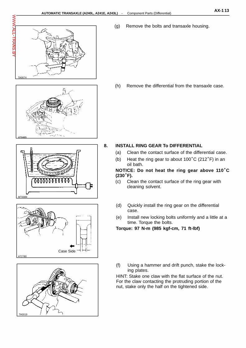
(g) Remove the bolts and transaxle housing.
(h) Remove the differential from the transaxle case.
8. INSTALL RING GEAR To DIFFERENTIAL(a) Clean the contact surface of the differential case.
(b) Heat the ring gear to about 100°C (212°F) in anoil bath.
NOTICE: Do not heat the ring gear above 110 °C(230°F).(c) Clean the contact surface of the ring gear with
cleaning solvent.
(d) Quickly install the ring gear on the differentialcase.
(e) Install new locking bolts uniformly and a little at atime. Torque the bolts.
Torque: 97 N-m (985 kgf-cm, 71 ft-lbf)
(f) Using a hammer and drift punch, stake the lock-ing plates.
HINT: Stake one claw with the flat surface of the nut.For the claw contacting the protruding portion of thenut, stake only the half on the tightened side.
TA0019
-AUTOMATIC TRANSAXLE (A240L, A241E, A243L) Component Parts (Differential)AX-1 13W
WW.ALL-TR
ANS.BY

AT8004
AT8005
9. INSTALL OIL SEAL OF TRANSAXLE CASE(a) Using SST and a hammer, drive in a new oil seal.SST 09350-32014 (09351-32130, 09351-32111)(b) Coat the lip of the seal with MP grease.
10. INSTALL OIL SEAL OF TRANSAXLE HOUSING(a) Using SST and a hammer, drive in a new oil seal.SST 09350-32014 (09351-32130, 09351-32150)(b) Coat the lip of oil seal with MP grease.
AX-1 14-AUTOMATIC TRANSAXLE (A240L, A241E, A243L) Component Parts (Differential)W
WW.ALL-TR
ANS.BY

INSTALLATION OF COMPONENT PARTS(See pages AX-16 to AX-21 )Disassembly, inspection and assembly of each component group have been indicated in the precedingchapter. Before assembly, make sure again that all component groups are assembled correctly.If something wrong is found in a certain component group during assembly, inspect and repair this groupimmediately.Recommended ATF: DEXRON� II
GENERAL NOTES:1. The automatic transmission is composed of highly precision-finished parts, necessitating
careful inspection before assembly because even a small nick could case fluid leakage oraffect performance.
2. Before assembling new clutch discs, soak them in automatic transmission fluid for at leastfifteen minutes.
3. Apply automatic transmission fluid on sliding or rotating surfaces of parts before assembly.4. Use petroleum jelly to keep small parts in their place.5. Do not use adhesive cements on gaskets and similar parts.6. When assembling the transmission, sure to use new gaskets and O-rings.7. Dry all parts with compressed air-never use shop rags.
-AUTOMATIC TRANSAXLE (A240L, A241E, A243L) Installation of Component PartsAX-1 15W
WW.ALL-TR
ANS.BY

8. Be sure to install the thrust bearings and races in the correct direction and position.
AT2955
AX-1 16-AUTOMATIC TRANSAXLE (A240L, A241E, A243L) Installation of Component PartsW
WW.ALL-TR
ANS.BY

AT3065
AT2915
AT2913
A B C D E F G H
FrontBearingRace
OuterDiameter
37.3(1.469)
45.0(1.772)
37.9(1.492) ←
43.0(1.693)
41.8(1.646)
InnerDiameter
24.1(0.949)
28.0(1.102)
22.0(0.866) ←
30.5(1.201)
30.0(1.181)
ThrustBearing
OuterDiameter
A241EA243L
37.6(1.480)
45.0(1.772)
36.1(1.421) ←
42.0(1.654)
57.7(2.272)
45.2(1.780)
43.7(1.720)
A240L37.61.4801
45.011.7721
36.1(1.421) ←
42.0(1.654)
57.7(2.272)
45.2(1.780) ←
InnerDiameter
A241EA243L
24.0(0.945)
30.0(1.181)
22.2(0.874) ←
28.9(1.138)
41.0(1.614)
31.0(1.220) ←
A240L24.0(0.945)
30.0(1.181)
22.2(0.874) ←
28.9(1.138)
41.0(1.614)
31.0(1.220) ←
RearBearingRace
OuterDiameter
37.6(1.480)
35.011.3781
35.7(1.406)
42.0(1.654)
InnerDiameter
22.2(0.874)
19.0(0.748)
23.0(0.906)
27.1(1.067)
mm (in.)
1. INSTALL BEARING To TRANSAXLE HOUSING(a) Using SST and a press, press the bearing into
the transaxle housing.SST 09350-32014 (09351-32140)
SST
(b) Install the bearing stopper with a bolt.
2. INSTALL NEW GASKET AND OIL TUBE APPLYCOVERInstall the new gasket and oil tube apply cover, andtighten the three bolts.
-
-
- - -
- - -
-AUTOMATIC TRANSAXLE (A240L, A241E, A243L) Installation of Component PartsAX-1 17W
WW.ALL-TR
ANS.BY

AT2911
AT0593
AT2910
Q00980
AT2956
3. INSTALL OIL TUBES(a) Using a plastic hammer, install the three (A241E)
or four (A240L, A243L) oil tubes.NOTICE: Be careful not to bend or damage the tubes.
A240L, A243LOnly
(b) Install the flour tube clamps.
4. INSTALL BEARING TO TRANSMISSION CASEUsing SST and a press, press the bearing into thetransmission case.SST 09350-32014 (09351-32090)
SST
5. INSTALL B 4 ACCUMULATOR PISTON AND SPRING
6. INSTALL OIL GALLERY COVER AND GASKET(a) Clean the threads of the screws and case with
white gasoline.
(b) Install the new gasket and oil gallery cover inplace.
(c) Install and tighten the three bolts.
AX-1 18-AUTOMATIC TRANSAXLE (A240L, A241E, A243L) Installation of Component PartsW
WW.ALL-TR
ANS.BY

Q00981
AT0548
AT2959
AT0545
AT0547
(d) Apply seal packing or equivalent to the six screws.Seal packing: Part No. 08833 - 00070, THREE BOND
1324 or equivalent(e) Using a torx wrench, install and tighten the three
screws.
7. INSTALL MANUAL VALVE SHAFT AND LEVER(a) Install the parking lock rod to the manual valve
lever.
(b) Slide in the shaft and install the washer, newspacer and manual lever.
(c) Install the retaining spring.HINT: Make sure there is a washer between the retain-ing spring and case.
8. INSTALL PIN(a) Using a pin punch and hammer, drive in the pin.
(b) Position the spacer and stake it.
9. INSTALL CAM GUIDE BRACKETInstall the cam guide bracket and then install the park-ing lock rod into the guide bracket.
-AUTOMATIC TRANSAXLE (A240L, A241E, A243L) Installation of Component PartsAX-1 19W
WW.ALL-TR
ANS.BY

AT0544
AT0700
AT0701
AT7931
Clamp Groove
10. INSTALL PARKING LOCK SLEEVEInstall the parking lock sleeve protruding portion up-ward.
11. PLACE STOPPER PLATEPlace the stopper plate on the protruding portion oflock sleeve.
12. INSTALL GUIDE SLEEVE AND SPRING
13. INSTALL PARKING LOCK PAWL, PAWL SHAFT ANDSHAFT CLAMP(a) Install the parking lock pawl.
(b) Insert the parking lock pawl shaft and install theshaft clamp.
AT7890
AX-120-AUTOMATIC TRANSAXLE (A240L, A241E, A243L) Installation of Component PartsW
WW.ALL-TR
ANS.BY

AT2962
AT2963
AT8483
AT2960
AT2888
14. INSTALL FIRST AND REVERSE BRAKE PISTON(a) Install the two new O-rings to the piston.
(b) Coat the O-rings with ATF.
(c) Place the piston into the bore of the case, facingthe spring seats upward.
(d) Using SST, press in the piston.SST 09350-32014 (09351-32040)HINT: Be careful not to damage the O-rings.(e) Remove SST.
SST
15. INSTALL PISTON RETURN SPRING AND SNAPRING(a) Install the piston return spring assembly and snap
ring in place.
(b) Set SST, and tighten the bolt gradually to com-press the springs.
SST 09350-32014 (09351-32040)NOTICE: Avoid bending the spring retainer by over-tightening the bolt.
SST
(c) Using snap ring pliers, install the snap ring.HINT: Visually check to make sure it is fully seated andcentered by the three lugs on the spring retainer.Be sure the end gap of snap ring is not aligned with thesprig retainer claw.(d) Remove SST.SST 09350-32014 (09351-32040)
SST
16. INSTALL UNDERDRIVE BRAKE PISTON(a) Coat the O-rings with ATF.
(b) Install the two new O-rings to the piston.
-AUTOMATIC TRANSAXLE (A240L, A241E, A243L) Installation of Component PartsAX-121W
WW.ALL-TR
ANS.BY

AT2901
AT2900
AT2899
AT7889
AT2961
(c) Place the piston into the case with the cup sideup, being careful not to damage the O-rings.
17. INSTALL RETURN SPRING
18. INSTALL PLATES, DISCS AND FLANGE(a) Install in order: D = Disc P = Plate F = Flange
P-D-P-D-P-D-FHINT: Install the Flange with the flat end facing down-ward.
(b) Place SST on the flange, and compress theflange with a press.
SST 09350-3201 (09351-32070)(c) Install the snap ring.HINT: Be sure the end gap of the snap ring is notaligned with one of the cutouts.
SST
19. CONFIRM THAT UNDERDRIVE BRAKE PISTONMOVESUsing compressed air, confirm that the underdrivebrake piston moves smoothly.
AX-122-AUTOMATIC TRANSAXLE (A240L, A241E, A243L) Installation of Component PartsW
WW.ALL-TR
ANS.BY

AT1292
AT1289
AT0597
Free
AT7987
17.3 - 18.2 mm
AT2898
20. INSTALL OIL SEAL RINGS TO TRANSMISSIONCASEInstall the two oil seals to the transmission case.
21. INSTALL UNDERDRIVE ONE-WAY CLUTCH
22. INSTALL ANTI-RATTLE CLIPIn the place shown in the figure (the space between theone-way clutch outer race and case), push the anti-rattle clip in until you hear the ”click”.
Lock
23. INSTALL UNDERDRIVE CLUTCH ASSEMBLY(a) Align the flukes of discs in the underdrive brake.
(b) Install the clutch assembly.
(c) Turn the clutch assembly. The clutch assemblyshould turn freely counterclockwise and shouldlock clockwise.
24. CHECK HEIGHT OF CLUTCH ASSEMBLYUsing vernier calipers, check the height from the sleeveto the inner race.Height: 17.3 - 18.2 mm (0.681 - 0.717 in.)
-AUTOMATIC TRANSAXLE (A240L, A241E, A243L) Installation of Component PartsAX-123W
WW.ALL-TR
ANS.BY

AT7999
AT1293
AT1294
Bearing A240LA241E,A243L
Outer diameter 43.7 (1.720) 45.2 (1.780)
Inner diameter 31.0 (1.220) 31.0 (1.220)
AT2896
SST
AT8482
mm (in.)
25. CHECK PISTON STROKE OF UNDERDRIVECLUTCH(a) Set a dial indicator (long type pick or SST) as
shown.SST 09350-32014 (09351-32190)
(b) Applying and releasing the compressed air (392 -785 kPa, 4 - 8 kg/cm2, 57 - 114 psi), measure theunderdrive clutch piston stroke.
Piston stroke:A240L 1.50 - 1.86 mm (0.0591 - 0.0732 in.)A241E, A243L
1.21 - 1.55 mm (0.0476 - 0.0610 in.)If the piston stroke is less than limit, parts may have beenmisassembled. Check them.If the piston stroke is nonstandard, select another flange.HINT: There are two different flange thickness.Flange thicknesses:
A240L 2.04 mm (0.0803 in.)2.40 mm (0.0945 in.)
A241E, A243L 2.30 mm (0.0906 in.)2.50 mm (0.0984 in.)2.70 mm (0.1063 in.)
26. INSTALL BEARING WITH RAGEInstall the thrust bearing with race, with the bearing fac-ing upward.
27. INSTALL SUN GEAR To CASEInstall the sun gear of the counter shaft to the case.
28. INSTALL COUNTER SHAFT ASSEMBLY(a) Align the flukes of the discs in the underdrive
clutch.
(b) Install the counter shaft assembly.
AX-124-AUTOMATIC TRANSAXLE (A240L, A241E, A243L) Installation of Component PartsW
WW.ALL-TR
ANS.BY

AT0533
AT8084
AT0603
SST
AT0076
AT0601
29. CHECK HEIGHT OF COUNTER SHAFTUsing vernier calipers, measure the distance betweenthe tip of the counter shaft and bolt seat of the clutchsupport.Height: 33.3 - 35.5 mm (1.311 - 1.398 in.)
30. INSTALL THRUST NEEDLE BEARINGBearing: Outer diameter 57.7 mm (2.272 in.)
Inner diameter 41.0 mm (1.614 in.)
31. INSTALL COUNTER DRIVEN GEARUsing SST and press, press in the driven gear.SST 09350-32014 (09351-32100, 09351-32140)
SST
32. TIGHTEN NEW LOCK NUT(a) Using SST to hold the driven gear, tighten a new
lock nut.SST 09330-00021 and 09350-32014 (09351-32032)Torque: 157 N-m (1,600 kgf-cm, 116 ft-lbf)(b) Remove SST.
33. CHECK END PLAY OF COUNTER SHAFTUsing a dial indicator, measure the end play of thecounter shaft.End play: 0.23 - 0.89 mm (0.0091 - 0.0360 in.)
-AUTOMATIC TRANSAXLE (A240L, A241E, A243L) Installation of Component PartsAX-125W
WW.ALL-TR
ANS.BY

AT0523
AT2892
AT8034
AT8039
AT0604
34. STAKE LOCK NUTUsing a punch and hammer, stake the lock nut.
35. INSTALL SNAP RING To TRANSMISSION CASEUsing snap ring pliers, install the snap ring to the trans-mission case.
36. INSTALL INTERMEDIATE SHAFT
37. INSTALL TRANSAXLE REAR COVER(a) Remove any packing material and be careful not to
get oil on the contacting surfaces of the transaxlerear cover or transmission case.
(b) Apply seal packing to the rear cover as shown.Seal packing: Part No. 08833 - 00090, THREE BOND
1131, LOCTITE 518 or equivalent.
Seal Packing
(c) Install and tighten the thirteen bolts.Torque: 29 N-m (300 kgf-cm, 22 ft-lbf)HINT: Each bolt length (mm) is indicated in the figure.
AX-126-AUTOMATIC TRANSAXLE (A240L, A241E, A243L) Installation of Component PartsW
WW.ALL-TR
ANS.BY

AT0527
AT0606
AT2893
AT0526
AT5602
A241E38. INSTALL NEW APPLY GASKETS
Install the two (A241E) or three (A240L, A243L) newapply gaskets.HINT: The oil seal may be inserted with either end up ordown.
A240L, A243L
39. INSTALL GOVERNOR DRIVEN GEAR(a) Install the thrust washer.
(b) Install the governor driven gear.
40. CHECK INTERMEDIATE SHAFTMake sure that the intermediate shaft turns smoothly.
-AUTOMATIC TRANSAXLE (A240L, A241E, A243L) Installation of Component PartsAX-127W
WW.ALL-TR
ANS.BY
AT5829
AT3139
AT0610
AT7892
AT0607
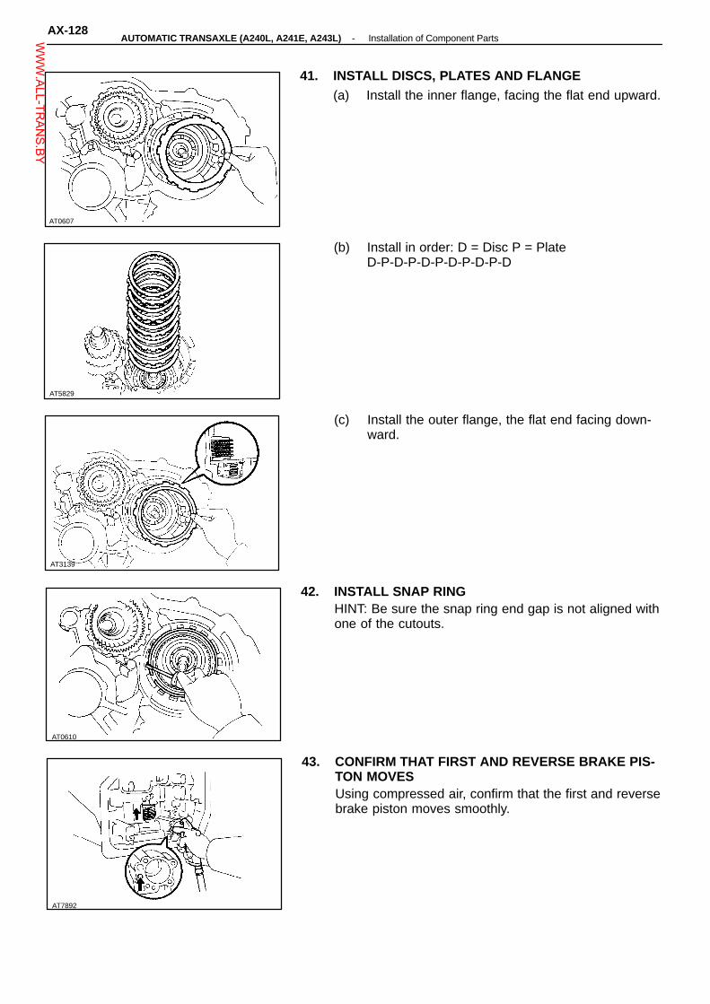
41. INSTALL DISCS, PLATES AND FLANGE(a) Install the inner flange, facing the flat end upward.
(b) Install in order: D = Disc P = PlateD-P-D-P-D-P-D-P-D-P-D
(c) Install the outer flange, the flat end facing down-ward.
42. INSTALL SNAP RINGHINT: Be sure the snap ring end gap is not aligned withone of the cutouts.
43. CONFIRM THAT FIRST AND REVERSE BRAKE PIS-TON MOVESUsing compressed air, confirm that the first and reversebrake piston moves smoothly.
AX-128-AUTOMATIC TRANSAXLE (A240L, A241E, A243L) Installation of Component PartsW
WW.ALL-TR
ANS.BY

AT8086
AT0612
AT0613
AT0323
Align
Outer diameter Inner diameter
Front Race 37.3 (1.4699) 24.1 (0.949)
Bearing 37.6 (1.480) 24.0 (0.945)
Rear Race 37.6 (1.480) 22.0 (0.874)
mm (in.)Bearing and races:
44. INSTALL REAR PLANETARY RING GEAR TO CASE(a) Coat the races and bearing with petroleum jelly,
and install them onto the ring gear as shown.
(b) Using a screwdriver, align the flukes of the discs.
(c) Install the rear planetary ring gear into the case.
45. INSTALL REAR PLANETARY GEAR(a) Coat the thrust washer with petroleum jelly and
install it onto the planetary gear.HINT: Make sure that the different lug shapes matchthe openings on the gear.
(b) Align the spline of the planetary gear with theflukes of the discs and install the planetary gearinto the first and reverse brake discs.
AT0614
-AUTOMATIC TRANSAXLE (A240L, A241E, A243L) Installation of Component PartsAX-129W
WW.ALL-TR
ANS.BY

AT5704
A
AT2965
Lock
AT2966
AT0618
AT0798
(c) Check that part A of the rear planetary gear isbelow the upper surface of the flange.Rear
PlanetaryGear
Flange
46. INSTALL NO. 2 ONE-WAY CLUTCH(a) Place the one-way clutch into the case, the shiny
side facing upward.
(b) Install the one-way clutch onto the inner racewhile turning the planetary gear clockwise withSST.
SST 09350-32014 (09351-32050)(c) Check that the planetary gear turns freely clock-
wise and locks counterclockwise.
Free
SST
(d) Coat the thrust washer with petroleum jelly andinstall it onto the planetary gear.Thrust Washer
47. INSTALL SNAP RINGBe sure the end gap of the snap ring is not aligned withone of the cutouts.
48. INSTALL SECOND BRAKE INTO CASE(a) Install the flange, the flat side facing upward.
AX-130-AUTOMATIC TRANSAXLE (A240L, A241E, A243L) Installation of Component PartsW
WW.ALL-TR
ANS.BY

AT7990
AT2967
AT0621
AT0622
AT0620
(b) Install the discs and plates in order.D = Disc P = Plate
D-P-D-P-D-P
49. INSTALL SECOND BRAKE PISTON RETURNSPRINGInstall each of the springs over the protrusions in thecase.
50. INSTALL SECOND COAST BRAKE BAND GUIDEInstall the band guide so that its tip touches the case.
51. INSTALL SECOND BRAKE DRUM INTO CASEAlign the groove of the drum with the bolt and place itinto the case.
52. INSTALL SNAP RING(a) Place the snap ring into the case so that the end
gap is installed into the groove.
(b) While compressing the piston return springs overthe drum with hammer handles, install the snapring.
HINT: Be sure the end gap of the snap ring is notaligned with one of the cutouts.
-AUTOMATIC TRANSAXLE (A240L, A241E, A243L) Installation of Component PartsAX-131W
WW.ALL-TR
ANS.BY

AT2592
AT7891
AT0626
AT8088
AT0627
53. INSTALL SECOND BRAKE DRUM GASKETDriven in a new drum gasket until it makes contact withthe second brake drum.
54. CONFIRM THAT SECOND BRAKE PISTON MOVESUsing compressed air, confirm that the second brakepiston moves smoothly.
55. INSTALL SECOND BRAKE HUB NO. 1 ONE-WAYCLUTCH(a) Using a screwdriver, align the flukes of the discs
in the second brake.
(b) Align the spline of the hub with the flukes of thediscs and install the hub to the second brake discs.
56. CHECK SECOND BRAKE HUB INSTALLATION DIS-TANCECheck the distance between the surface of the secondbrake hub and rear planetary gear.Distance: Approx. 5 mm (0.20 in.)
AX-132-AUTOMATIC TRANSAXLE (A240L, A241E, A243L) Installation of Component PartsW
WW.ALL-TR
ANS.BY

Outer diameter Inner diameter
Front Race 37.9 (1.492) 22.0 (0.866)
Bearing 36.1 (1.421) 22.2 (0.874)
Rear Race 35.0 (1.378) 19.0 (0.748)
AT8056
AT0628
Outer diameter Inner diameter
Bearing 45.0 (1.772) 30.0 (1.181)
Race 45.0 (1.772) 28.0 (1.102)
AT0631
AT2593
Rear Race
AT2759
Baring
Bearing and races:
Bearing and races: mm (in.)
mm (in.)
57. INSTALL SUN GAR AND SUN GEAR INPUT DRUM(a) Coat the thrust washer with petroleum jelly and
install it on the sun gear input drum.
(b) While turning the sun gear clockwise, install it intothe No. 1 one-way clutch.
58. INSTALL FRONT PLANETARY GEAR(a) Coat the race and bearing with petroleum jelly
and install them onto the planetary gear.
Race
(b) Install the planetary gear.
Front Race 59. INSTALL FRONT PLANETARY RING GEAR(a) Coat the races and bearing with petroleum jelly
and install them onto the planetary ring gear.
-AUTOMATIC TRANSAXLE (A240L, A241E, A243L) Installation of Component PartsAX-133W
WW.ALL-TR
ANS.BY

AT2023
Outer diameter Inner diameter
Front Race 37.9 (1.492) 22.0 (0.866)
Bearing 36.1 (1.421) 22.2 (0.874)
Rear Race 35.7 (1.406) 23.0 (0.906)
AT2969
AT0635
Outer diameter Inner diameter
Bearing 42.0 (1.654) 28.9 (1.138)
Race 42.0 (1.654) 27.1 (1.067)
AT2970
AT2968
Bearing and race: mm (in.)
(b) Install the ring gear.
HINT: If the planetary ring gear and the other parts areinstalled correctly into the case, the end of the bushingwith the ring gear flange will be flush with a shoulder ofthe intermediate shaft or under.
(c) Coat the races and bearing with petroleum jelly andinstall them onto the tip of ring gear flange as shown.
Bearing and races: mm (in.)
Front Race
Rear Race
60. INSTALL SECOND COAST BRAKE BAND(a) Place the band into the case.
(b) Install the pin through the oil pump mounting bolthole.
61. INSTALL FORWARD CLUTCH AND DIRECT CLUTCH(a) Coat the race and bearing with petroleum jelly,
and install them onto the forward clutch drum.
AX-134-AUTOMATIC TRANSAXLE (A240L, A241E, A243L) Installation of Component PartsW
WW.ALL-TR
ANS.BY

AT1984 AT0381
Bushing
AT0349
AT2971
AT2595
AT0350
(b) Coat the clutch drum thrust washer with petroleumjelly, and install it onto the direct clutch drum withthe oil groove facing upward.
(c) Using a screwdriver, align the flukes of discs inthe direct clutch.
(d) Mesh the hub with the flukes of the direct clutchwhile turning the clutch drum or forward clutch.
HINT: If the flukes of the discs are meshed with the hubcorrectly, the end of the bushing with the direct clutchdrum will be flush with the surfaces of the forwardclutch.
Thrust Washer
(e) Place the direct clutch and forward clutch into thecase.
(f) While rotating the forward clutch to mesh the frontplanetary ring gear and discs, install them.
(g) Check the distance between A and B shown inthe illustration.
Distance: Approx. 3 mm (0.118 in.)
-AUTOMATIC TRANSAXLE (A240L, A241E, A243L) Installation of Component PartsAX-135W
WW.ALL-TR
ANS.BY

AT8484
Sealant
AT5711
AT2766
AT2972
AT0525
62. INSTALL DIFFERENTIAL
63. INSTALL TRANSAXLE HOUSING(a) Remove any packing material and be careful not to
get oil on the contacting surfaces of the transaxlehousing or transmission case.
(b) Apply seal packing to the transaxle housing asshown.
Seal packing: Part No. 08833 - 00090, THREE BOND1131, LOCTITE 518 or equivalent.
SealPacking
(c) Apply sealant to the bolt threads.Sealant: Part No. 08833 - 00080, Adhesive 1344,
THREE BOND 1344, LOCTITE 242 or equiv-alent
(d) Install and tighten the bolts.Torque: 29 N-m (300 kgf-cm, 22 ft-lbf)HINT: Each bolt length (mm) is indicated in the illustra-tion.
64. CHECK PRELOAD OF DIFFERENTIAL SIDE BEARING(See page AX-1 12)
65. INSTALL OIL PUMP INTO CASE(a) Coat the race with petroleum jelly and install it
onto the stator shaft.Race: Outer diameter 43.0 mm (1.693 in.)
Inner diameter 30.5 mm (1.201 in.)
(b) Coat the new O-ring with ATF, and install it topump body.
AX-136-AUTOMATIC TRANSAXLE (A240L, A241E, A243L) Installation of Component PartsW
WW.ALL-TR
ANS.BY

AT0637
AT0638
AT2974
AT2870
AT2973
(c) Place the oil pump through the input shaft, andalign the bolt holes of the pump body with thetransmission case.
(d) Hold the input shaft, and lightly press the oil pumpbody to slide the oil seal rings on the stator shaftthrough the direct clutch drum.
NOTICE: Do not push on the oil pump strongly, or theoil seal ring will stick to the direct clutch drum.
(e) Install and tighten the six bolts.Torque: 25 N-m (250 kgf-cm, 18 ft-lbf)
66. MEASURE THRUST PLAY OF INPUT SHAFTMeasure the thrust play in axial direction.Thrust play: 0.3 - 0.9 mm (0.012 - 0.035 in.)If the play is not as specified, select and replace therace for the end of stator shaft.HINT: There are two different thickness of races. If nec-essary, select one of them.Race thickness: 0.8 mm (0.031 in.)
1.4 mm (0.055 in.)
67. CHECK INPUT SHAFT ROTATIONMake sure that the input shaft rotates smoothly.
68. INSTALL SECOND COAST BRAKE PISTON(a) Install the two new O-rings to the cover.HINT: Coat the O-rings with ATF before installing.
O-Rings
-AUTOMATIC TRANSAXLE (A240L, A241E, A243L) Installation of Component PartsAX-137W
WW.ALL-TR
ANS.BY

AT2869
AT2867
SST
AT2865
AT8302
SST
(b) Install the spring, piston and cover into the bore.
(c) Using SST, install the snap ring while pressingthe cover.
SST 09350-31014 (09351-32050)(d) Check that the front end of the piston rod con-
tacts the center of the second brake band de-pression.
69. MEASURE PISTON STROKE OF SECOND COASTBRAKE(a) Apply a small amount of paint to the piston rod at
the point it meets the case as shown in the il-lustration.
(b) Using SST, measure the piston stroke applyingand releasing the compressed air (392 - 785 kPa,4 - 8 kg/cm2, 57 - 114 psi) as shown.
SST 09240-00020Piston stroke: 1.5 - 3.0 mm (0.059 - 0.118 in.)If it is still more than standard value, replace the brakeband with a new one.
70. INSTAL ACCUMULATOR PISTONS AND SPRINGS(a) Coat the new O-rings with ATF, and install them
to the pistons.
AX-138-AUTOMATIC TRANSAXLE (A240L, A241E, A243L) Installation of Component PartsW
WW.ALL-TR
ANS.BY

AT3036
A240L
Spring Free length mm (in.) Color
C1Outer 74.1 (2.917) Pink
Inner 41.0 (1.614) Pink
C2No. 1 15.5 (0.610) Pink
No. 2 62.54 (2.462) Pink
B2No. 1 15.5 (0.610) Green
No. 2 64.5 (2.539) Green
C3Outer 65.2 (2.570) Blue
Inner 48.0 (1.890) Orange
AT5703
Outer
A243LA241E
Spring Free length mm (in.) Color
C1Outer 77.8 (3.063) None
Inner 42.5 (1.673) None
C2 71.54 (2.817)Blue andLight Blue
B2 56.68 (2.231) Yellow
C3 61.47 (2.420) White
Spring Free length mm (in.) Color
C1Outer 77.8 (3.063) None
Inner 42.50 (1.6732) None
C2 64.8 (2.551) Yellow
B2No. 1 35.18 (1.3850) Yellow
No. 2 56.68 (2.2315) Yellow
C3 64.72 (2.5480) Red and Yellow
AT3225
Outer
A240L
AT5706
Cover
No. 1
Inner
(b) Install the pistons and springs to the case.
Outer
Inner
A241E, A243L
(A243L)
Gasket-
(A240L)
(c) Place the cover with a new gasket and graduallytighten the bolts little a time in sequence.
Torque: 10 N-m (100 kgf-cm, 7 ft-lbf)
No. 2
Inner
No. 1 Spring(B2)
(A241E)
-AUTOMATIC TRANSAXLE (A240L, A241E, A243L) Installation of Component PartsAX-139W
WW.ALL-TR
ANS.BY

AT0643
AT5692
AT7991
AT5616
AT5707
71. INSTALL SECOND BRAKE APPLY GASKET
72. INSTALL THROTTLE CABLE IN CASEPush the cable through the hole on the case, beingcareful not to damage the O-ring. Check for full seat-ing.NOTICE: In subsequent work, to avoid breaking thecable fitting do not roll the case over the cable.
73. INSTALL SOLENOID WIRE
74. INSTALL VALVE BODY(a) Coat the manual valve with ATF and install it to
the valve body.
(b) Connect the connecting rod to the manual valvelever.
AX-140-AUTOMATIC TRANSAXLE (A240L, A241E, A243L) Installation of Component PartsW
WW.ALL-TR
ANS.BY
AT3146
A241E
AT3146
A240L, A243L
AT3135
AT2584
A241E
AT0108
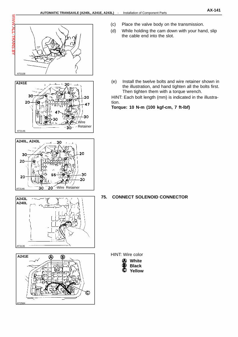
(c) Place the valve body on the transmission.
(d) While holding the cam down with your hand, slipthe cable end into the slot.
(e) Install the twelve bolts and wire retainer shown inthe illustration, and hand tighten all the bolts first.Then tighten them with a torque wrench.
HINT: Each bolt length (mm) is indicated in the illustra-tion.Torque: 10 N-m (100 kgf-cm, 7 ft-lbf)
WireRetainer
-Wire Retainer
75. CONNECT SOLENOID CONNECTORA243LA240L
HINT: Wire colorWhiteBlackYellow
-AUTOMATIC TRANSAXLE (A240L, A241E, A243L) Installation of Component PartsAX-141W
WW.ALL-TR
ANS.BY

AT5685
AT2975
AT2855
AT2854
76. INSTALL MANUAL DETENT SPRING(a) Install the detent spring and cover in place, and
install the bolt (length: 16 mm).
(b) Hand tighten the bolt first, then tighten the boltwith a torque wrench.
Torque: 10 N-m (100 kgf-cm, 7 ft-lbf)(c) Check that the manual valve lever is in contact
with the center of the roller at the tip of the detentspring.
77. INSTALL OIL TUBES(a) Tap the tubes with a plastic hammer to install
them into the positions indicated in the illustration.NOTICE: Be careful not to bend or damaged the tubes.
(b) Install the oil tube clamp and bracket.HINT: Each bolt length (mm) is indicated in the illustra-tion. Hand tighten ail bolts first, then tighten them with atorque wrench.Torque: 10 N-m (100 kgf-cm, 7 ft-lbf)
78. INSTALL OIL STRAINER(a) Install the new gasket to the oil strainer.
Gasket
(b) Install the oil strainer with the three bolts.HINT: each bolt length (mm) is indicated in the illustra-tion.
AT2853
AX-142-AUTOMATIC TRANSAXLE (A240L, A241E, A243L) Installation of Component PartsW
WW.ALL-TR
ANS.BY

AT7992
AT7919
AT2852
AT7932
AT2976
79. INSTALL THREE MAGNETS IN OIL PANNOTICE: Make sure that the magnets do not interferewith the oil tubes.
80. INSTALL OIL PAN(a) Install a new gasket to the oil pan and install them
to the transmission.
(b) Tighten the eighteen bolts.Torque: 4.9 N-m (50 kgf-cm, 43 in.-lbf)
(c) Install a new gasket to the drain plug and install itto the oil pan.
Torque: 17 N-m (175 kgf-cm, 13 ft-lbf)
81. (A241E)INSTALL SPEED SENSOR AND SENSOR ROTOR(a) Install the sensor adaptor with three bolts.
(b) Install the sensor rotor.
-AUTOMATIC TRANSAXLE (A240L, A241E, A243L) Installation of Component PartsAX-143W
WW.ALL-TR
ANS.BY

AT2852
AT5684
AT7926
AT7887
AT5683
(c) Install a new O-ring to the sensor cover.
(d) Install the sensor cover to the transmission andthen install the sensor cover bracket with the twobolts.
Torque: 13 N-m (130 kgf-cm, 9 ft-lbf)
(e) Coat a new O-ring with ATF and install it to thespeed sensor.
(f) Install the speed sensor and retaining plate.Torque: 10 N-m (100 kgf-cm, 7 ft-lbf)
82. (A240L, A241E, A243L)INSTALL GOVERNOR BODY(a) Install the governor oil strainer to the case.
(b) Install a new gasket to governor body adaptor.
(c) Install the governor body adaptor with three bolts.
AX-144-AUTOMATIC TRANSAXLE (A240L, A241E, A243L) Installation of Component PartsW
WW.ALL-TR
ANS.BY

AT2850
AT2848
AT5652
AT5641
AT2851
(d) Install the governor body and thrust washer.
Thrust Washer
(e) Install a new O-ring to the cover.
O-Rings
(f) Install the cover to the transmission and theninstall the two cover brackets with the twobolts.
Torque: 13 N-m (130 kgf-cm, 9 ft-lbf)
83. INSTALL SOLENOID WIRE RETAINING PLATEInstall the retaining plate with the bolt.
84. INSTALL THROTTLE CABLE RETAINING PLATEInstall the retaining plate with the bolt.
-AUTOMATIC TRANSAXLE (A240L, A241E, A243L) Installation of Component PartsAX-145W
WW.ALL-TR
ANS.BY

AT5730
AT7762
NeutralBasicLine
AT5638
AT5637
AT5639
85. INSTALL NEUTRAL START SWITCH(a) Install the neutral start switch to the manual valve
shaft.
(b) Install the packing. (A240L, A241E)
(c) Install the nut and lock stopper.
(d) Tighten the nut.Torque: 6.9 N-m (70 kgf-cm, 61 in.-lbf)
(e) Temporarily install the manual shift lever.
(f) Turn the lever counterclockwise until it stops, thenturn it clockwise two notches.
(g) Remove the manual shift lever.
(h) Align the groove and neutral basic line as shown.
(i) Install and tighten the two bolts.Torque: 5.4 N-m (55 kgf-cm, 48 in.-lbf)
Groove
(j) Using a screwdriver, stake the nut with the nutstopper.
(k) Install the manual shift lever with the washer, andtighten the nut.
86. INSTALL FILLER TUBE AND TRANSMISSION DIP-STICK
87. INSTALL TWO OIL COOLER PIPES
AX-146-AUTOMATIC TRANSAXLE (A240L, A241E, A243L) Installation of Component PartsW
WW.ALL-TR
ANS.BY

AT3367N-m (kgf-cm, ft-lbf)
Drain Plug
Bracket
Oil Tube
♦ Gasket
♦ Gasket♦ Gasket
Valve Body
Spring130 (130, 9) ♦ O-Ring
Manual ShiftLever
Stopper
7.4 (75, 65 in.-lbf) Snap Ring
Cover
Second CoastBrake Piston
Manual Valve Lever Shaft
Spring
Parking Rod
Plate
GovernorCover
♦ O-Ring Union Elbow
Thrust Washer
♦ GasketGovernor Body7.4 (75, 65 in.-lbf)
AdapterThrottle Cable
Spring Plate ♦ O-Ring
REMOVAL OF COMPONENT PARTS(A241H)COMPONENTS
130 (130, 9)Plug Oil Pressure Switch
Strainer
PlugHose
♦ O-Ring
27 (275, 20)SolenoidWire
♦ O-Ring
Manual Valve Lever
Pin
Spring♦ O-RingPlate Washer
♦ Oil SealNeutral Start Switch
Manual Valve
6.9 (70, 61 in.-lbf)♦ Gasket
Detent Spring
Spring
ClampPiston
Oil Strainer
Cover
Magnet
Clamp
Oil Pan
♦ Gasket: Specified torque
♦ Non-reusable part
-AUTOMATIC TRANSAXLE (A241H) Removal of Component PartsAX-147W
WW.ALL-TR
ANS.BY

N-m (kgf-cm, ft-lbf)AT3368
Flange
Second CoastBrake Band Guide
Second BrakeDrum Seal
Disc
Flange
Snap Ring
Thrust Washer
Disc
RaceRear PlanetaryGear
Thrust Washer
Bearing
Front PlanetaryGear
One-W ay ClutchRace
Pin
22 (225, 16)
Direct Clutch
Forward ClutchOil Pump
Front PlanetaryRing Gear
Race
Piston ReturnSpring
Snap Ring Intermediate Shaft
SnapRing
Race
Rear PlanetaryRing Gear
COMPONENTS (Cont’d)
Second CoastBrake Band
♦ O-Ring
Thrust Washer
Race
Bearing
Bearing
Planetary Sun Gear
Bearing
Race
One-W ayClutch No. 2
Snap Ring
Flange
Bearing
TransaxleRear Cover
PlateSecond BrakePiston
25 (250, 18)
Second Brake Apply Gasket
Plate
: Specified torque
♦ Non-reusable part
AX-148-AUTOMATIC TRANSAXLE (A241H) Removal of Component PartsW
WW.ALL-TR
ANS.BY

AT3366
: Specified torque♦ Apply Gasket
Sleeve
♦ Oil Seal Ring
♦ Snap Ring
Spring
Counter DrivenGear
Under Drive Input Shaft withPlanetary Gear
♦ Nut
♦ BearingGovernor Driven Gear
Under DriveOne-W ay Clutch
Drain Plug♦ Gasket
♦ Apply Gasket
♦ Gasket
Transaxle HousingCover
Plate
Apply Gasket
Oil Tube
Bearing
Clamp
Retainer
Thrust Washer
Differential
Under Drive Clutch
COMPONENTS (Cont’d)
Clamp
Retainer
Oil SealRing
Transfer Assembly
Clamp
♦ Gasket
29 (300, 22)
♦ O-Ring
29 (300, 22)
Bearing
157 (1,600, 116)
Thrust Washer
See page AX-151 Plate
Parking LockShaft
Parking LockLever
Spring Guide
Differential Side GearIntermediate Shaft
PlatePlate
N-m (kgf-cm, ft-lbf) 13 (130, 9)♦ Non-reusable part�Precoated part
-AUTOMATIC TRANSAXLE (A241H) Removal of Component PartsAX-149W
WW.ALL-TR
ANS.BY

AT8042
AT8074
AT8069
AT8496
AT8079
SEPARATE BASIC SUBASSEMBLY
1. REMOVE TRANSFER ASSEMBLY(a) Remove six nuts.
(b) Using a plastic hammer, remove the transfer as-sembly from the transaxle.
2. REMOVE DIFFERENTIAL SIDE GEAR INTERMEDI-ATE SHAFT(a) Screw in suitable bolt with washer into the side
gear intermediate shaft.
(b) Using SST, remove the side gear intermediateshaft.
SST 09520-32012
SST
3. REMOVE MANUAL SHIFT LEVERRemove the nut, washer and manual shift lever.
4. REMOVE NEUTRAL START SWITCH(a) Using a screwdriver, unstake the nut stopper.
(b) Remove the nut, nut stopper and packing.
AX-150-AUTOMATIC TRANSAXLE (A241H) Removal of Component PartsW
WW.ALL-TR
ANS.BY

AT8043
AT0501
AT0502
AT8045
AT8053
(c) Remove the two bolts and neutral start switch.
5. REMOVE THROTTLE CABLE RETAINING PLATERemove the bolt and plate.
6. REMOVE SOLENOID WIRE RETAINING PLATERemove the bolt and plate.
7. REMOVE GOVERNOR BODY(a) Remove the two bolts and cover brackets.
(b) Using a screwdriver, remove the governor cover.HINT: Tape the screwdriver tip before use so as not todamage the cover of transaxle.
-AUTOMATIC TRANSAXLE (A241H) Removal of Component PartsAX-151W
WW.ALL-TR
ANS.BY

AT2850
AT8071
AT8051
AT8057
AT0102
(c) Remove the O-ring from the cover.
O-Ring
(d) Remove the governor body with thrust washer.
(e) Remove the three bolts and governor body adap-tor with gasket.
(f) Remove the governor oil strainer.
8. REMOVE PAN AND GASKET(a) Remove the eighteen bolts.
(b) Remove the pan by lifting the transmission case.NOTICE: Do not turn the transmission over as it willcontaminate the valve body with the foreign materialsin the bottom of the pan.(c) Remove the gasket.
(d) Place the transmission on wooden blocks to pre-vent damage to the pipe.
AX-152-AUTOMATIC TRANSAXLE (A241H) Removal of Component PartsW
WW.ALL-TR
ANS.BY

AT0103
AT3449
AT3428
AT3432
AT2854
9. EXAMINE PARTICLES IN PANRemove the magnets and use them to collect any steelchips. Look carefully at the chips and particles in thepan and on the magnet to anticipate what type of wearyou will find in the transmission:Steel (magnetic) bearing, gear and plate wear. . . . . . . Brass (non-magnetic) bushing wear. .
10. TURN TRANSMISSION OVER
11. REMOVE OIL STRAINER(a) Remove the three bolts and oil strainer.
(b) Remove the gasket.
12. REMOVE OIL TUBES(a) Remove the two bolts and tube bracket.
(b) Remove the tube clamp bolt and clamp.
(c) Pry up both tube ends with a large screwdriverand remove the five tubes.
-AUTOMATIC TRANSAXLE (A241H) Removal of Component PartsAX-153W
WW.ALL-TR
ANS.BY

AT3135
AT3433
AT0108
AT0507
AT0653
13. REMOVE MANUAL DETENT SPRING
14. DISCONNECT SOLENOID CONNECTOR
15. REMOVE VALVE BODY(a) Remove the twelve bolts and wire retainer as
shown.
(b) Disconnect the throttle cable from the cam.
(c) While disconnecting the manual valve connectingrod from the manual valve lever, remove the valvebody.
16. REMOVE THROTTLE CABLE FROM CASEPull out the throttle cable.
AX-154-AUTOMATIC TRANSAXLE (A241H) Removal of Component PartsW
WW.ALL-TR
ANS.BY

AT1290
AT2860
A12861
AT3036
AT3114
17. REMOVE SOLENOID WIRE
18. REMOVE SECOND BRAKE APPLY GASKET
19. REMOVE C3 ACCUMULATOR PISTON AND SPRINGUsing low-pressure compressed air (98 kPa, 1 kg/cm2,14 psi), pop out the piston into a rag. Force air into thehole shown and remove the piston and spring.
20. REMOVE ACCUMULATOR PISTONS AND SPRINGS(a) Loosen the five bolts one turn at a time until the
spring tension is released.
(b) Remove the cover, gasket and spring on the B2piston.No. 1 Spring
(B2)
-AUTOMATIC TRANSAXLE (A241H) Removal of Component PartsAX-155W
WW.ALL-TR
ANS.BY

AT2863
AT3141
AT2865
AT2866
SST
AT3111
(c) Remove the C1 piston and two springs.
(d) Using low-pressure compressed air (98 kPa, 1kg/cm2, 14 psi), pop out the C2 piston into a rag.Force air into the hole shown and remove thepiston and spring.
(e) Using low-pressure compressed air (98 kPa, 1kg/cm2, 14 psi), pop out the B2 piston into a rag.Force air into the hole shown and remove the pis-ton and spring.
21. MEASURE PISTON STROKE OF SECOND COASTBRAKE(a) Apply a small amount of paint to the piston rod at
the point it meets the case as shown in the il-lustration.
(b) Using SST, measure the piston stroke applyingand releasing the compressed air (392 - 785 kPa,4 - 8 kg/cm2, 57 - 114 psi) as shown.
SST 09240-00020Piston stroke: 1.5 - 3.0 mm (0.059 - 0.118 in.)If the piston stroke exceed the limit, inspect the brakeband.
AX-156-AUTOMATIC TRANSAXLE (A241H) Removal of Component PartsW
WW.ALL-TR
ANS.BY

AT8070
AT2867
AT2869
AT2870
AT2868
22. REMOVE SECOND COAST BRAKE PISTON(a) Using SST, remove the snap ring.SST 09350-32014 (09351-32050)
SST
(b) Using low-pressure compressed air (98 kPa, 1kg/cm2, 14 psi), pop out the cover into a rag.Force air into the hole shown.
(c) Remove the cover, piston and spring.
(d) Remove the two O-rings from thecover.
23. REMOVE OIL PUMP(a) Remove the six bolts holding the oil pump to the
transmission case.
(b) Using SST, remove the oil pump.SST 09350-32014 (09351-32061)NOTICE: Be careful not to drop or damage the racesand bearing behind oil pump.(c) Remove SST from the oil pump:
SST
-AUTOMATIC TRANSAXLE (A241H) Removal of Component PartsAX-157W
WW.ALL-TR
ANS.BY

AT3035
AT8049
AT0651
AT0652
A
(d) Remove the race from the oil pump.
AT0352
(e) Remove the O-ring from the oil pump.
24. REMOVE OIL SEAL RINGSRemove the two oil seal rings.
25. REMOVE DIRECT CLUTCH
26. REMOVE FORWARD CLUTCH(a) Remove the forward clutch with bearing and race.
AX-158-AUTOMATIC TRANSAXLE (A241H) Removal of Component PartsW
WW.ALL-TR
ANS.BY

28. REMOVE FRONT PLANETARY RING GEAR
AT0515
AT2873
AT2875
AT2876
AT3461
(b) Remove the thrust washer, bearing and races fromthe forward clutch.
27. REMOVE SECOND COAST BRAKE BAND(a) Push the pin with a small screwdriver and remove
it from the bolt hole of the oil pump mounting.
(b) Remove the brake band.
(a) Remove the front planetary ring gear with bearingand race.
(b) Remove the bearing and race from the ring gear.
29. REMOVE FRONT PLANETARY GEAR(a) Remove the front planetary gear with race.
-AUTOMATIC TRANSAXLE (A241H) Removal of Component PartsAX-159W
WW.ALL-TR
ANS.BY

AT2877
AT2878
AT0518
AT0519
AT7891
(b) Remove the races and bearing from the planetarygear or sun gear.
30. REMOVE SUN GEAR, SUN GEAR INPUT DRUM ANDTHRUST WASHER
31. REMOVE SECOND BRAKE HUB AND NO. 1 ONE-WAY CLUTCH
32. CONFIRM THAT SECOND BRAKE PISTON MOVESUsing compressed air, confirm that the second brakepiston moves smoothly.
33. REMOVE SECOND COAST BRAKE BAND GUIDE
AX-160-AUTOMATIC TRANSAXLE (A241H) Removal of Component PartsW
WW.ALL-TR
ANS.BY
AT2880
AT2859
AT2881
AT2882
AT2879
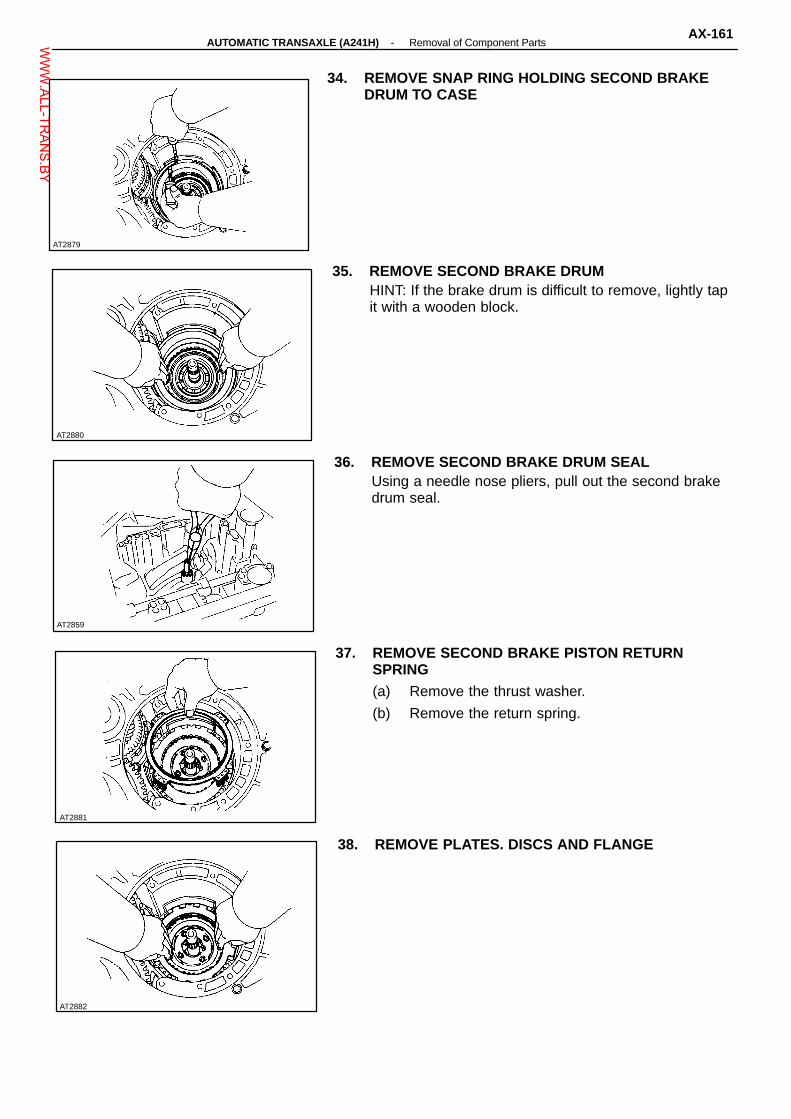
34. REMOVE SNAP RING HOLDING SECOND BRAKEDRUM TO CASE
35. REMOVE SECOND BRAKE DRUMHINT: If the brake drum is difficult to remove, lightly tapit with a wooden block.
36. REMOVE SECOND BRAKE DRUM SEALUsing a needle nose pliers, pull out the second brakedrum seal.
37. REMOVE SECOND BRAKE PISTON RETURNSPRING(a) Remove the thrust washer.
(b) Remove the return spring.
38. REMOVE PLATES. DISCS AND FLANGE
-AUTOMATIC TRANSAXLE (A241H) Removal of Component PartsAX-161W
WW.ALL-TR
ANS.BY

AT2885
AT2883
AT2884
AT0139
39. REMOVE SNAP RING HOLDING NO. 2 ONE-WAYCLUTCH OUTER RACE TO CASEUsing a screwdriver, remove the snap ring.
40. REMOVE NO. 2 ONE-WAY CLUTCH AND REARPLANETARY GEAR(a) Remove the No. 2 one-way clutch and rear plan-
etary gear with thrust washer.
(b) Remove the thrust washer from the gear.
41. REMOVE REAR PLANETARY RING GEAR(a) Remove the rear planetary ring gear with bearing
and races.
(b) Remove the bearing and races from the ringgear.
AT0324
AX-162-AUTOMATIC TRANSAXLE (A241H) Removal of Component PartsW
WW.ALL-TR
ANS.BY

AT2886
AT2887
AT0521
AT0522
AT7892
42. CONFIRM THAT FIRST AND REVERSE BRAKE PIS-TON MOVESUsing compressed air, confirm that the first and reversebrake piston moves smoothly.
43. REMOVE SNAP RING HOLDING FLANGE TO CASEUsing a screwdriver, remove the snap ring.
44. REMOVE FLANGES, PLATES AND DISCS.
45. REMOVE TRANSAXLE REAR COVER(a) Remove the thirteen bolts.
(b) Tap off the circumference of the cover with a plas-tic hammer to remove the cover from the transmis-sion case, and remove the cover.
-AUTOMATIC TRANSAXLE (A241H) Removal of Component PartsAX-163W
WW.ALL-TR
ANS.BY

AT0523
AT0376
Snap Ring
AT2888
AT2889
AT2892
46. REMOVE INTERMEDIATE SHAFTRemove the intermediate shaft from the transmissioncase.
47. REMOVE SNAP RINGUsing snap ring pliers, remove the snap ring.
SST
48. REMOVE SNAP RING(a) Set SST, and tighten the bolt gradually to com-
press the springs until the snap ring is free fromthe spring seat.
SST 09350-32014 (09351-32040)
Spring Seat
(b) Using snap ring pliers, remove the snap ring.
(c) Remove SST.SST 09350-32014 (09351-32040)
SST
49. REMOVE RETURN SPRINGRemove the return spring and snap ring.
AX-164-AUTOMATIC TRANSAXLE (A241H) Removal of Component PartsW
WW.ALL-TR
ANS.BY

AT2891
AT8077
AT3348
AT0526
AT2890
50. REMOVE PISTON FROM TRANSMISSION CASEWITH COMPRESSED AIR(a) Apply compressed air into the oil passage of the
case to remove the piston.HINT: Hold the piston so it is not horizontal and blowwith the gun slightly away from the oil hole.(b) If the piston does not pop out with compressed air,
use needle-nose pliers to remove it.
51. REMOVE O-RINGS FROM PISTONRemove the two O-rings from the piston.
52. REMOVE TRANSAXLE HOUSINGRemove the nineteen bolts and transaxle housing.
53. REMOVE DIFFERENTIAL ASSEMBLY
54. REMOVE GOVERNOR’ DRIVEN GEAR(a) Remove the governor driven gear.
-AUTOMATIC TRANSAXLE (A241H) Removal of Component PartsAX-165W
WW.ALL-TR
ANS.BY

AT0627
AT2893
AT7996
AT0529
AT2895 AT2894
(b) Remove the thrust washer.
55. REMOVE APPLY GASKETSRemove the three gaskets.
56. INSPECT COUNTER SHAFT END PLAYUsing a dial indicator, measure the end play of thecounter shaft.End play: 0.23 - 0.89 mm (0.0091 - 0.0350 in.)
57. REMOVE COUNTER SHAFT LOCK NUTS(a) Using a chisel and hammer, unstake the counter
shaft lock nut on both sides.
(b) Using SST, remove the lock nut of the driven gearside.
SST 09330-00021, 09350-32014 (09351-32032)SST
AX-166-AUTOMATIC TRANSAXLE (A241H) Removal of Component PartsW
WW.ALL-TR
ANS.BY

AT0532
AT0533
AT2896
AT0535
AT0530 AT0531
SST (c) Using SST to hold the driven gear, remove thelock nut of the another side.
SST 09330-0002109350-32014 (09351-32032, 09351-32170)
SST
58. REMOVE COUNTER DRIVEN GEARUsing SST, remove the driven gear.SST 09350-32014 (09351-32061)
SST
59. REMOVE THRUST NEEDLE SEARING
60. REMOVE COUNTER SHAFT ASSEMBLYPull out the counter shaft assembly.
61. REMOVE THRUST BEARING WITH RACERemove the thrust bearing with race from the countershaft assembly.
-AUTOMATIC TRANSAXLE (A241H) Removal of Component PartsAX-167W
WW.ALL-TR
ANS.BY

AT2898
AT8072
AT7999
AT2897
AT7889
62. CHECK PISTON STROKE OF UNDERDRIVECLUTCH(a) Set a dial indicator (long type pick or SST) as
shown.SST 09350-32014 (09351-32190)
SST
(b) Applying and releasing the compressed air (392785 kPa, 4 - 8 kg/cm2, 57 - 114 psi), measurethe underdrive clutch piston stroke.
Piston stroke: 1.50 - 1.86 mm (0.0591 - 0.0732 in.)If the piston stroke is nonstandard, select anotherflange.HINT: There are two different flange thickness.Flange thickness: 2.04 mm (0.0803 in.)
2.40 mm (0.0945 in.)
63. REMOVE UNDERDRIVE CLUTCH DRUM AND ANTI-RATTLE CLIP
64. CONFIRM THAT UNDERDRIVE BRAKE PISTONMOVESUsing compressed air, confirm that the underdrivebrake piston moves smoothly.
65. REMOVE OIL SEAL RINGSRemove the two oil seal rings.
AX-168-AUTOMATIC TRANSAXLE (A241H) Removal of Component PartsW
WW.ALL-TR
ANS.BY

AT2900
AT2901
AT2902
AT2903
AT2899
SST
66. REMOVE FLANGE, PLATES AND DISCS(a) Using SST and press, press in the flange until the
snap ring is free from the flange.SST 09350-32014 (09351-32070)(b) Using a screwdriver, remove the snap ring.
(c) Remove the flange, three plates and discs.
67. REMOVE RETURN SPRING
68. REMOVE UNDERDRIVE BRAKE PISTONUsing low-pressure compressed air (98 kPa, 1 kg/cm2,14 psi), pop out the brake piston into a rag.Force air into the hole shown and remove the brake pis-ton.
69. REMOVE O-RINGS FROM PISTONRemove the two O-rings from the piston.
-AUTOMATIC TRANSAXLE (A241H) Removal of Component PartsAX-169W
WW.ALL-TR
ANS.BY

AT2904
AT0541
AT8058
AT0543
AT0544
70. REMOVE PARKING LOCK PAWL STOPPER PLATE,TORSION SPRING AND SPRING GUIDE
71. REMOVE PAWL SHAFT CLAMP
72. REMOVE PARKING LOCK PAWL SHAFT AND LOCKPAWL
73. REMOVE PARKING LOCK SLEEVE
74. REMOVE CAM GUIDE BRACKETRemove the cam guide bracket as shown.
AX-170-AUTOMATIC TRANSAXLE (A241H) Removal of Component PartsW
WW.ALL-TR
ANS.BY

AT2905
AT2906
AT0547
AT0548
AT8082
75. REMOVE TRANSMISSION CASE PLATE
76. REMOVE MANUAL VALVE SHAFT SPACERUsing a screwdriver and hammer, unstake the spacerand remove it.
77. REMOVE PINUsing a pin punch and hammer, drive out the pin.
78. REMOVE MANUAL VALVE SHAFT AND LEVER(a) Remove the retaining spring.
(b) Slide out the manual valve shaft and remove themanual valve lever and washer.
-AUTOMATIC TRANSAXLE (A241H) Removal of Component PartsAX-171W
WW.ALL-TR
ANS.BY
AT2908
Torx Wrench
AT5643
AT2910
AT0555
AT2907
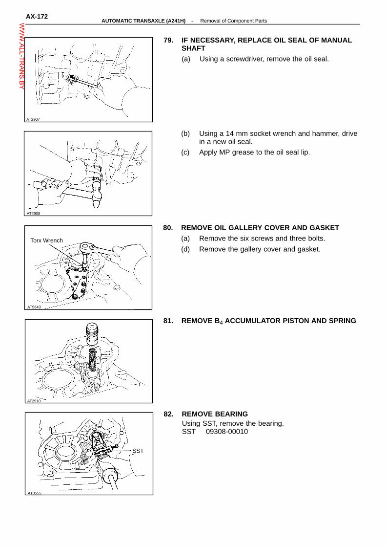
79. IF NECESSARY, REPLACE OIL SEAL OF MANUALSHAFT(a) Using a screwdriver, remove the oil seal.
(b) Using a 14 mm socket wrench and hammer, drivein a new oil seal.
(c) Apply MP grease to the oil seal lip.
80. REMOVE OIL GALLERY COVER AND GASKET(a) Remove the six screws and three bolts.
(d) Remove the gallery cover and gasket.
81. REMOVE B4 ACCUMULATOR PISTON AND SPRING
82. REMOVE BEARINGUsing SST, remove the bearing.SST 09308-00010
SST
AX-172-AUTOMATIC TRANSAXLE (A241H) Removal of Component PartsW
WW.ALL-TR
ANS.BY

AT3347
AT3346
AT3343
AT2915
AT8073
83. REMOVE APPLY GASKETRemove the apply gasket from the transaxle housing.
84. REMOVE OIL TUBES(a) Using a torx wrench, remove the four tube
clamps.
TorxWrench
(b) Using a screwdriver, remove the four oil tubes.
85. REMOVE OIL TUBE APPLY COVER, GASKET ANDSTRAINERRemove the three bolts and a torx screw, and removethe cover and gasket.
Torx Screw
86. REMOVE BEARING(a) Remove the bolt and stopper.
-AUTOMATIC TRANSAXLE (A241H) Removal of Component PartsAX-173W
WW.ALL-TR
ANS.BY

AT7995
AT7994
(b) Using SST, remove the bearing.SST 09612-65014
SST
(c) Remove the oil seal ring.
AX-174-AUTOMATIC TRANSAXLE (A241H) Removal of Component PartsW
WW.ALL-TR
ANS.BY

AT5701AT2841
Specified torque ♦ GasketSpring
♦ O-Ring
BoltB4 Accumulator Piston
Spring
Spring
Snap Ring
Cover
Second CoastBrake Piston
♦ Gasket
Oil Pan
Clamp
6.9 (70, 61 in.-lbf)♦ Gasket
Transaxle Hosing♦ Gasket
Detent Spring Plate
5.4 (55, 48 in.-lbf)
O/D Solenoid Wire
Governor Cover
♦ O-Ring
Strainer
Governor Driven GearGovernor Body
♦ O-Ring
♦ O-Ring
Detent Spring
Thrust Washer
♦ O-Ring
Magnet
Retaining Plate
♦ Apply Gasket
Neutral StartSwitch
♦ O-Ring
REMOVAL OF COMPONENT PARTS(A240L)COMPONENTS
Governor Body Adaptor
♦ GasketThrust Washer
Transaxle Case Throttle Cable
Oil Tube
Cover Bracket
Oil Apply Tube Cover
Manual Valve ManualShift Lever
Valve Body
Oil TubeOil Strainer
♦ Gasket
BracketDrain Plug
♦ Gasket
�Screw
Spring
♦ O-Ring
Spring♦ O-Ring
Accumulator PistonC3 Accumulator Piston
Oil Gallery Cover
N-m (kgf-cm, ft-lbf)
Cover♦ Non-reusable part�Precoated part
AX-16-AUTOMATIC TRANSAXLE (A240L) Removal of Component PartsW
WW.ALL-TR
ANS.BY

N-m (kgf-cm, ft-lbf)AT2842
Piston Return Spring
Flange
Flange
♦ Second Brake Drum Seal
Disc
Snap Ring♦ O-Ring
Snap Ring
Thrust Washer
Race
Plate♦ O-Ring
Bearing
Front PlanetaryGear
BearingBearing
Race Forward Clutch
RaceRace
Front PlanetaryRing Gear
Second CoastBrake Band
Thrust Washer
Transaxle Rear Cover
Snap Ring
♦ Second Brake Apply Gasket
Rear PlanetaryRing Gear
Second Brake Drum
COMPONENTS (Cont’d)
Sun GearInput Drum
One-W ay Clutch
Bearing
Thrust Washer
Direct ClutchOil Pump
25 (250, 18)
Race
Thrust WasherPin
BearingNo. 2 One-Way Clutch withRear Planetary Gear
Flange
Snap Ring
Disc
Piston Return Spring
Snap Ring
Snap Ring
Intermediate Shaft
Second Coast Brake Band Guide
Plate First and ReverseBrake Piston
Specified torque♦ Non-reusable part
-AUTOMATIC TRANSAXLE (A240L) Removal of Component PartsAX-17W
WW.ALL-TR
ANS.BY

AT2843: Specified torque
WasherPin
Return Spring
13 (130, 9) Cam Guide Bracket
Spring
Manual Valve Shaft
Plate
Needle Bearing
♦ Lock Nut
Disc
Oil Seal Ring
Roller Bearing
Counter Shaft Assembly
Underdrive Clutch
Parking LockPawl
Clamp
Manual Valve Lever
N-m (kgf-cm, ft-lbf)
DifferentialPawl Shaft Lock Pawl Shaft
COMPONENTS (Cont’d)
Bearing
Counter Driven Gear
Underdrive Brake Piston
Retaining Spring
Flange
157 (1,600, 116)
♦ O-Ring
Snap Ring
♦ Oil Seal
5.4 (55, 48 in.-lbf)
Parking Lock Rod
Guide Sleeve Parking Lock Sleeve
Stopper Plate
♦ Spacer
♦ Non-reusable part
AX-18-AUTOMATIC TRANSAXLE (A240L) Removal of Component PartsW
WW.ALL-TR
ANS.BY
COMPONENT PARTS(See page AX-48 to AX-88 )
General NotesThe instructions here are organized so that you work on only one component group at a time.This will help avoid confusion from similar-locking parts of different subassemblies being on your work-bench at the same time.The component groups are inspected and repaired from the converter housing side.As much as possible, complete the inspection, repair and assembly before proceeding to the next com-ponent group. If a component group can not be assembled because parts are being ordered, be sure tokeep all parts of that group in a separate container while proceeding with disassembly, inspection, repairand assembly for other component groups.
GENERAL CLEANING NOTES:1. All disassembled parts should be washed clean with any fluid passages and holes blown
through with compressed air.2. When using compressed air to dry parts, always aim away from yourself to prevent acciden-
tally spraying automatic transmission fluid or kerosene in your face.3. The recommended automatic transmission fluid kerosene should be used for cleaning.
PARTS ARRANGEMENT:
1. After cleaning, the parts should be arranged in proper order to allow efficient inspection,repairs, and reassembly.
2. When disassembling a valve body, be sure to keep each valve together with the corre-sponding spring.
3. New brakes and clutches that are to be used for replacement must be soaked in transmis-sion fluid for at least fifteen minutes before assembly.
GENERAL ASSEMBLY:1. All oil seal rings, clutch discs, clutch plates, rotating parts, and sliding surfaces should be
coated with transmission fluid prior to reassembly.2. All gaskets and rubber O-rings should be replaced.3. Make sure that the ends of a snap ring are not aligned with one of the cutouts and are
installed in the groove correctly.4. If a worn bushing is to be replaced, the subassembly containing that bushing must be re-
placed.5. Check thrust bearings and races for wear or damage. Replace if necessary.6. Use petroleum jelly to keep parts in place.
-AUTOMATIC TRANSAXLE (A241H) Component Parts (General Notes)AX-175W
WW.ALL-TR
ANS.BY

♦ Non-reusable part
: Specified torque
Strainer
O/D Solenoid
Plate
Lower Valve Body
No. 2 PressureRegulator ValveBody
Plate
♦ No. 1 Gasket
Clamp
N-m (kgf-cm, ft-lbf)
AT3406
Valve BodyCOMPONENTS
Oil Tube
Upper Valve Body
Plate♦ Gasket
♦ No. 2 Gasket
♦ Gasket
♦ O-Ring
6.5 (65, 56 in.-lbf)
AT3399
(Disassembly of Valve Body)1. NOTE NUMBER OF ADJUSTING RINGS
HINT: Count the number of adjusting rings before dis-assembly of the valve body because the throttle pres-sure is changed according to the number. (Some of thevalve bodies do not have any adjusting rings.)
2. NOTE POSITION OF PLUNGER SLEEVENote which step at the end of the plunger sleeve is incontact with the valve body.HINT: Be certain to check this before disassembly be-cause the line pressure changes according to the partof the plunger sleeve which comes into contact with thevalve body.
AT8372
AX-176-AUTOMATIC TRANSAXLE (A241H) Component Parts (Valve Body)W
WW.ALL-TR
ANS.BY

AT8356
AT8357
AT8358
AT8359
AT8355
3. SEPARATE NO. 2 PRESSURE REGULATOR VALVEBODY(a) Remove the tube clamp and oil tube.
(b) Remove the four bolts, No. 2 pressure regulatorvalve body, gasket and plate from the upper valvebody.
4. REMOVE O/D SOLENOID(a) Remove the solenoid.
(b) Remove the O-ring from the solenoid.
5. REMOVE LOWER VALVE BODY COVER AND OILSTRAINER(a) Remove the seventeen bolts, cover, plate and
two gaskets.
(b) Remove the oil strainer.
6. SEPARATE UPPER VALVE BODY AND LOWERVALVE BODY(a) Remove the eight bolts from the upper valve
body.
-AUTOMATIC TRANSAXLE (A241H) Component Parts (Valve Body)AX-177W
WW.ALL-TR
ANS.BY

AT8360
AT7982
(b) Remove the five bolts from the lower valve body.
(c) Hold the plate to the lower valve body and lift offthe lower valve body.
HINT: Be careful that the valves, springs and strainer donot fall out.
AX-178-AUTOMATIC TRANSAXLE (A241H) Component Parts (Valve Body)W
WW.ALL-TR
ANS.BY

Cut-back Valve
Key
Plug
Pin
Plug
Cam
Washer
Darn ShiftPlug
Pin
Plug
Check Ball
Lock-Up RelayValve Sleeve
Lock-Up RelayValve
PrimaryRegulatorValve Sleeve
Pin
No. 2 PressureRegulator Valve Plunger
Primary RegulatorPlunger
Primary RegulatorPlunger Sleeve
2nd CoastModulator Valve ‘
(Upper Valve Body)COMPONENTS
No. 2 PressureRegulator Valve
Washer
Primary RegulatorValve
Adjusting Ring(See page AT-175)
Lock-Up RelayControl Valve
Vibrating StopperCheck Ball
SpringPin
Check BallKeyThrottle Valve
Throttle Valve Sleeve
Throttle Modulator Valve
Accumulator Con-trol Valve
Plug
Pin
AT3379Q00982
Plug
-AUTOMATIC TRANSAXLE (A241H) Component Parts (Valve Body)AX-179W
WW.ALL-TR
ANS.BY

AT3382 AT3384
CheckBall
Pin
Pin
Pin
Pin
Key
Check Ball
CheckBall
SpringFree lengthmm (in.)
Coil OuterDiametermm (in.)
Number ofCoils Color
Primary Regulator Valve Spring 66.7 (2.626) 18.6 (0.732) 12.5 Purple
Lock-Up Relay Valve Spring 18.8 (0.740) 5.1 (0.201) 14.5 None
2nd Coast Modulator Valve Spring 32.6 (1.283) 8.3 (0.327) 12.5 Blue
Down Shift Plug Spring 30.0 (1.181) 8.7 (0.343) 12.5 Blue
Throttle Valve Spring 29.2 (1.150) 9.2 (0.3622) 9.5 Light Green
Throttle Modulator Valve Spring 29.9 (1.177) 9.0 (0.354) 15.5 Green
Accumulator Control Valve Spring 38.2 (1.504) 10.0 (0.394) 11.5 Yellow
No. 2 Pressure Regulator Valve Spring 29.4 (1.157) 7.5 (0.295) 14.0 Red
CheckBall
SPECIFICATIONS OF VALVE BODY SPRING
HINT: During re-assembly please refer to the spring specifications above to help discriminate be-tween the different springs.
LOCATION OF KEYS, PINS, VIBRATING STOPPER AND CHECK BALLS
Check Bail
VibratingStopper
Key
Pin
Key
Pin
CheckBall
CheckBall
AX-180-AUTOMATIC TRANSAXLE (A241H) Component Parts (Valve Body)W
WW.ALL-TR
ANS.BY
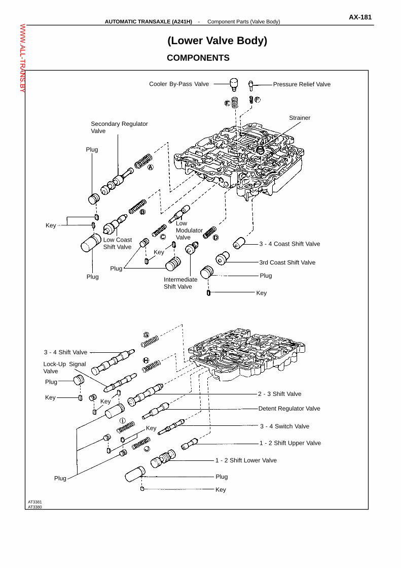
Key
Plug
1 - 2 Shift Upper Valve
3 - 4 Switch Valve
Key2 - 3 Shift Valve
Lock-Up SignalValve
Key
PlugPlug
Low CoastShift Valve
Key
Plug
Strainer
Cooler By-Pass Valve
LowModulatorValve
Key
(Lower Valve Body)
COMPONENTS
Pressure Relief Valve
Secondary RegulatorValve
0
3 - 4 Coast Shift Valve
3rd Coast Shift Valve
Plug IntermediateShift Valve
3 - 4 Shift Valve
Plug
Key
Detent Regulator Valve
Key
1 - 2 Shift Lower Valve
Plug
AT3381AT3380
-AUTOMATIC TRANSAXLE (A241H) Component Parts (Valve Body)AX-181W
WW.ALL-TR
ANS.BY

AT3386 AT3388
Key
Key
Key
Key
Key
Pressure Relief Valve
Cooler By-pass Valve
Spring Free Lengthmm (in.)
Coil OuterDiametermm (in.)
Number ofCoils Color
Secondary Regulator Valve Spring 27.4 (1.079) 11.0 (0.433) 11.5 Blue
1 - 2 Shift Valve Spring 27.2 (1.071) 6.4 (0.252) 15.5 Yellow
Low Modulator Valve Spring 29.2 (1.150) 8.3 (0.327) 12.5 None
2 - 3 Shift Valve Spring 27.7 (1.091) 8.3 (0.327) 11.0 None
Cooler By-pass Valve Spring 18.3 (0.720) 12.0 (0.472) 6.5 Yellow
Pressure Relief Valve Spring 11.2 (0.441) 6.4 (0.252) 7.5 None
3 - 4 Shift Valve Spring 34.9 (1.374) 8.2 (0.323) 13.5 None
Lock-up Signal Valve Spring 41.4 (1.630) 8.2 (0.323) 14.5 White
Detent Regulator Valve Spring 32.0 (1.260) 8.3 (0.327) 15.5 Brown
3 - 4 Switch Valve Spring 30.9 (1.217) 7.0 (0.276) 18.5 None
SPECIFICATIONS OF VALVE BODY SPRING
HINT: During re-assembly please refer to the spring specifications above to help discriminate be-tween the different springs.
LOCATION OF KEYS, STRAINER AND VALVES
Key
Key
Key
Key
Key
Key
Strainer
AX-182-AUTOMATIC TRANSAXLE (A241H) Component Parts (Valve Body)W
WW.ALL-TR
ANS.BY
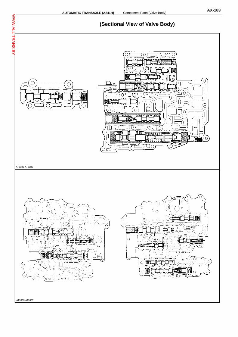
AT3383 AT3385
AT3389 AT3387
(Sectional View of Valve Body)
-AUTOMATIC TRANSAXLE (A241H) Component Parts (Valve Body)AX-183W
WW.ALL-TR
ANS.BY
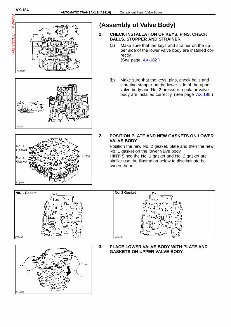
AT3409
AT3407
AT3496
No. 1 Gasket
AT3495
AT7983
AT3497
Plate
(Assembly of Valve Body)1. CHECK INSTALLATION OF KEYS, PINS, CHECK
BALLS, STOPPER AND STRAINER(a) Make sure that the keys and strainer on the up-
per side of the lower valve body are installed cor-rectly.(See page AX-182 )
(b) Make sure that the keys, pins, check balls andvibrating stopper on the lower side of the uppervalve body and No. 2 pressure regulator valvebody are installed correctly. (See page AX-180 )
2. POSITION PLATE AND NEW GASKETS ON LOWERVALVE BODYPosition the new No. 2 gasket, plate and then the newNo. 1 gasket on the lower valve body.HINT: Since the No. 1 gasket and No. 2 gasket aresimilar use the illustration below to discriminate be-tween them.
No. 1Gasket
No. 2Gasket
No. 2 Gasket
3. PLACE LOWER VALVE BODY WITH PLATE ANDGASKETS ON UPPER VALVE BODY
AX-184-AUTOMATIC TRANSAXLE (A241H) Component Parts (Valve Body)W
WW.ALL-TR
ANS.BY

AT8361
AT8362
AT3408
AT8369
Plate
AT8368
4. INSTALL AND FINGER TIGHTEN BOLTS IN LOWERVALVE BODY TO SECURE UPPER VALVE BODYInstall and finger tighten the five bolts.HINT: Each bolt length (mm) is indicated in the figure.
5. INSTALL AND FINGER TIGHTEN BOLTS IN UPPERVALVE BODYInstall and finger tighten the eight bolts.HINT: Each bolt length (mm) is indicated in the figure.
6. INSTALL LOWER VALVE BODY COVER(a) Make sure that the keys are installed correctly.
(See page AX-184 )
(b) Install the strainer.
(c) Position a new gasket and plate, and then anoth-er new gasket.
Gasket
Gasket
-AUTOMATIC TRANSAXLE (A241H) Component Parts (Valve Body)AX-185W
WW.ALL-TR
ANS.BY

AT7993
AT8364
AT3405
AT8365
AT8363
(d) Position the lower valve body cover.
(e) Install and finger tighten the seventeen bolts.HINT: Each bolt length (mm) is indicated in the figure.
7. INSTALL O/D SOLENOID(a) Apply ATF to a new O-ring.
(b) Install the O-ring to the solenoid.
(c) Install the solenoid.HINT: Each bolt length (mm), is indicated in the figure.Torque: 6.4 N-m (65 kgf-cm, 56 in.-lbf)
8. TIGHTEN EACH BOLTSTorque: 6.4 N-m (65 kgf-cm, 56 in.-lbf)(Lower valve body side)
(Upper valve body side)
AX-186-AUTOMATIC TRANSAXLE (A241H) Component Parts (Valve Body)W
WW.ALL-TR
ANS.BY

AT8367
AT8371
AT8366
Gasket
GasketPlate
9. INSTALL NO. 2 PRESSURE REGULATOR VALVEBODY(a) Install the gasket, plate and gasket on the upper
valve body.
(b) Install the No. 2 pressure regulator valve body onthe upper valve body.
(c) Install and tighten the four bolts.HINT: Each bolt length (mm) is indicated in the figure.Torque: 6.4 N-m (65 kgf-cm, 56 in.-Ibf)
10. INSTALL OIL TUBE(a) Install the oil tube.
(b) Install the clamp and torque the bolt.Torque: 6.4 N-m (65 kgf-cm, 56 in.-lbf)
-AUTOMATIC TRANSAXLE (A241H) Component Parts (Valve Body)AX-187W
WW.ALL-TR
ANS.BY

AT3365
♦ Left Side Bearing
♦ Oil Seal
Transmission OilBaffle
Ring Gear MountingLeft Case
Ring Gear
Pin
No. 2 Piston
124 (1,260, 91)
Plate
Gear MountingCase
♦ O-Ring
29 (300, 22)
Shaft Snap Ring
Flange
Speedometer Drive Gear
Differential PinionThrust Washer
Front DifferentialRight Case
Differential Pinion Shaft
: Specified torqueN-m (kgf-cm, ft-lbf)
Piston ReturnSpring
♦ Oil Seal Ring
DifferentialSide Gear
Differential SideThrust Washer No. 2
DifferentialCOMPONENTS
Ring Gear Mounting Right Case Bearing
Ring Gear Mounting RightCase Bearing Outer Race
Hole SnapRing
Clutch Disk
♦ O-Ring
♦ O-Ring
Shaft Snap Ring
No. 1 Piton
Piston Reaction Sleeve
Front DifferentialLeft Case
Differential Pinion
33 (340, 25)
Side GearThrust Washer
Differential SideThrust Washer No. 1
Plate Washer
♦ Non-reusable part
AX-188-AUTOMATIC TRANSAXLE (A241H) Component Parts (Valve Body)W
WW.ALL-TR
ANS.BY
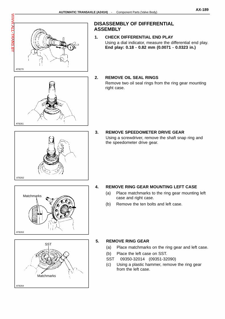
AT8261
AT8262
AT8263
AT8264
SST
AT8270
DISASSEMBLY OF DIFFERENTIALASSEMBLY
1. CHECK DIFFERENTIAL END PLAYUsing a dial indicator, measure the differential end play.End play: 0.18 - 0.82 mm (0.0071 - 0.0323 in.)
2. REMOVE OIL SEAL RINGSRemove two oil seal rings from the ring gear mountingright case.
3. REMOVE SPEEDOMETER DRIVE GEARUsing a screwdriver, remove the shaft snap ring andthe speedometer drive gear.
4. REMOVE RING GEAR MOUNTING LEFT CASE(a) Place matchmarks to the ring gear mounting left
case and right case.
(b) Remove the ten bolts and left case.
Matchmarks
5. REMOVE RING GEAR(a) Place matchmarks on the ring gear and left case.
(b) Place the left case on SST.SST 09350-32014 (09351-32090)(c) Using a plastic hammer, remove the ring gear
from the left case.
Matchmarks
-AUTOMATIC TRANSAXLE (A241H) Component Parts (Valve Body)AX-189W
WW.ALL-TR
ANS.BY

AT8265
AT8276
AT8277
Torx Wrench
AT8278
AT8377
6. REMOVE FRONT DIFFERENTIAL CASE(a) Remove the No. 2 thrust washer.
(b) Remove the front differential case from the ringgear mounting right case.
7. REMOVE FRONT DIFFERENTIAL LEFT CASE(a) Using a torx wrench, remove the eight screws
from the left case.
(b) Separate the left case and right case.NOTICE: Do not scratch the contact surface of theneedle bearing.
8. REMOVE DRIVE PINIONS AND SIDE GEARSRemove the following parts:� Differential pinion shaft� Shaft pin� Two pinion gears� Two pinion thrust washers� Two side gears� Two side gear thrust washers
9. REMOVE NO. 1 THRUST WASHER
AX-190-AUTOMATIC TRANSAXLE (A241H) Component Parts (Valve Body)W
WW.ALL-TR
ANS.BY

AT8279
AT8280
AT8271
AT7754
10. CHECK OPERATION OF DIFFERENTIAL LOCKCLUTCH PISTON(a) Plug one hole of the right case with your hand.
(b) Apply compressed air into the other hole and con-firm that the piston move.
11. REMOVE DIFFERENTIAL LOCK CLUTCH(a) Using a screwdriver, remove the snap ring.
(b) Remove the flange, seven discs and sevenplates.
(c) Place SST, and compress the return spring.SST 09350-32014 (09351-32070)(d) Using snap ring pliers, remove the snap ring.
SST
(e) Apply compressed air to the right case hole toremove the No. 1 piston.
(f) Remove the O-ring from the No. 1 piston.
AT8272
-AUTOMATIC TRANSAXLE (A241H) Component Parts (Valve Body)AX-191W
WW.ALL-TR
ANS.BY

AT8274
AT8275
AT7749
SST
AT8297
SST
AT8273
(g) Using a small screwdriver, remove the reactionsleeve and No. 2 piston.
(h) Remove the three O-rings from the reactionsleeve and No. 2 piston.
12. REMOVE TRANSAXLE CASE OIL SEALUsing a screwdriver, remove the oil seal from the trans-axle case.
13. REMOVE TRANSMISSION OIL BAFFLE
REPLACEMENT OF RING GEAR MOUNTINGCASE BEARINGS
1. REMOVE RING GEAR MOUNTING LEFT CASEBEARINGUsing SST, remove the bearing.SST 09950-00020, 09950-00030
2. INSTALL RING GEAR MOUNTING LEFT CASEBEARINGUsing a press and SST, press in the bearing.SST 09316-2001 1, 09350-32014 (09351-32090)
AX-192-AUTOMATIC TRANSAXLE (A241H) Component Parts (Valve Body)W
WW.ALL-TR
ANS.BY

AT7751
AT7752
AT8287
AT8286
AT7750
3. REMOVE RING GEAR MOUNTING RIGHT CASEBEARING(a) Using a chisel and hammer, cut out the bearing
cage.NOTICE: Do not damage to the case.
(b) Using a press and SST, press out the bearing in-ner race.
SST 09350-32014 (09351-32090), 09950-00020SST
4. INSTALL RING GEAR MOUNTING RIGHT CASEBEARINGUsing a press and SST, press in the new bearing.SST 09316-60010 (09316-00010), 09502-12010
SST
5. REMOVE RING GEAR MOUNTING CASE BEARINGOUTER RACES(Transaxle Housing Side)Using a pin punch and hammer, drive out the outer racefrom the transaxle housing.
(Transaxle Case Side)Using a brass bar and hammer, drive out the outer raceand plate washer.
-AUTOMATIC TRANSAXLE (A241H) Component Parts (Valve Body)AX-193W
WW.ALL-TR
ANS.BY
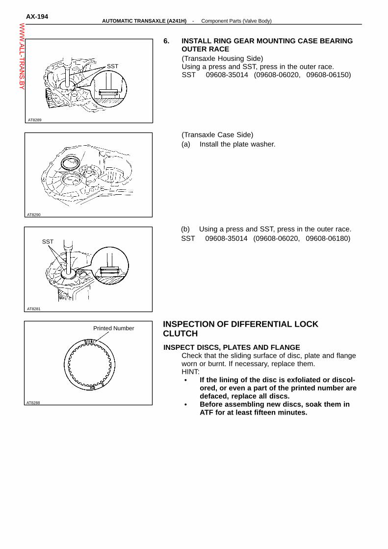
AT8289
AT8290
AT8281
Printed Number
6. INSTALL RING GEAR MOUNTING CASE BEARINGOUTER RACE(Transaxle Housing Side)Using a press and SST, press in the outer race.SST 09608-35014 (09608-06020, 09608-06150)
SST
(Transaxle Case Side)(a) Install the plate washer.
(b) Using a press and SST, press in the outer race.SST 09608-35014 (09608-06020, 09608-06180)SST
INSPECTION OF DIFFERENTIAL LOCKCLUTCH
INSPECT DISCS, PLATES AND FLANGECheck that the sliding surface of disc, plate and flangeworn or burnt. If necessary, replace them.HINT:� If the lining of the disc is exfoliated or discol-
ored, or even a part of the printed number aredefaced, replace all discs.
� Before assembling new discs, soak them inATF for at least fifteen minutes.
AT8288
AX-194-AUTOMATIC TRANSAXLE (A241H) Component Parts (Valve Body)W
WW.ALL-TR
ANS.BY

AT7753
AT7754
AT8282
Clutch Disc
Flange
AT3498
AT8471
ASSEMBLY OF DIFFERENTIAL ASSEMBLY
1. INSTALL DIFFERENTIAL LOCK CLUTCH PISTON(a) Coat the four O-rings with ATF.
(b) Install the four O-rings to the reaction sleeve andpistons.
(c) Install the No. 1, No. 2 pistons and reactionsleeve to the ring gear mounting right case.
2. INSTALL RETURN SPRING(a) Place the spring on the piston.
(b) Place SST on the spring retainer, and compressthe spring with a press.
SST 09350-32014 (09351-32070)(c) Using snap ring pliers, install the snap ring.
SST
3. INSTALL PLATE, DISCS AND FLANGE(a) Install the plate and discs.
Install in order: P = Plate D = DiscP-D-P-D-P-D-P-D-P-D-P-D-P-D
(b) Install the flange with a facing the flat end down-ward.
ClutchPlate
-AUTOMATIC TRANSAXLE (A241H) Component Parts (Valve Body)AX-195W
WW.ALL-TR
ANS.BY

AT8279
AT3499
AT8376
AT8283
AT7755
(c) Using a screwdriver, install the snap ring.
4. CHECK OPERATION OF DIFFERENTIAL LOCKCLUTCH PISTON(a) Plug the one hole with your hand.
(b) Apply compressed air into the other hole and besure that the piston move.
5. INSTALL NO. 1 THRUST WASHERNo. 1 ThrustWasher
6. CHECK AND ADJUST FRONT DIFFERENTIAL SIDEGEAR BACKLASH(Front Differential Left Case)(a) Install the following parts:� Side gear thrust washer� Side gear� Two differential pinion gear� Two pinion gear thrust washer� Pinion shaft� Pinion shaft pin
(b) Using a dial indicator, measure the backlash onepinion gear while holding the side gear toward thecase.
Backlash: 0.05 - 0.20 mm (0.0020 - 0.0079 in.)If not within specification select the side gear thrustwasher.NOTICE: Do not tighten the vise too tight.
AX-196-AUTOMATIC TRANSAXLE (A241H) Component Parts (Valve Body)W
WW.ALL-TR
ANS.BY

AT8284
AT8277
Torx Wrench
Mark Thickness mm (in.) Mark Thickness mm (in.)
A
B
C
D
1.00 (0.0394)
1.05 (0.0413)
1.10 (0.0433)
1.15 (0.0453)
E
F
G
1.20 (0.0472)
1.25 (0.0492)
1.30 (0.0512)
AT8285
AT8296
AT8375
(Front Differential Right Case)(a) Install the following parts:� Side gear thrust washer� Side gear� Two differential pinion gear� Two pinion gear thrust washer� Pinion shaft� Pinion shaft pin
(b) Using a dial indicator, measure the backlash onepinion gear while holding the side gear toward thecase.Backlash: 0.05 - 0.20 mm (0.0020 - 0.0079 in.)If not within specification select the side gearthrust washer.
7. INSTALL FRONT DIFFERENTIAL LEFT CASE(a) Install the left case to the right case.
(b) Using a torx wrench, torque the eight torx screws.Torque: 33 N-m (340 kgf-cm, 25 ft-lbf)NOTICE: Do not scratch the contact surface of theneedle bearing.
8. INSTALL FRONT DIFFERENTIAL CASE(a) Install the front differential case to the ring gear
mounting right case.
(b) Install the No. 2 thrust washer.
-AUTOMATIC TRANSAXLE (A241H) Component Parts (Valve Body)AX-197W
WW.ALL-TR
ANS.BY

AT7756
OilBath
MatchmarksAT8263
AT7757
AT8298
AT7758
100°C (212°F) 9. INSTALL RING GEAR(a) Clean the contact surface of the ring gear mount-
ing left case.
(b) Heat the ring gear to about 100°C (212°F) in anoil bath.
NOTICE: Do not heat the ring gear above 110 °C(230°F)(c) Clean the contact surface of the ring gear with
cleaning solvent.
(d) Then quickly install the ring gear on the left case.HINT: Align the matchmarks on the left case and ringgear.(e) Torque the ten bolts.Torque: 124 N-m (1,260 kgf-cm, 91 ft-lbf)
10. CHECK OPERATION OF FRONT DIFFERENTIALCheck that the front differential turns smoothly.
11. INSTALL SPEEDOMETER DRIVE GEAR(a) Place the speedometer drive gear on the ring
gear mounting case.
(b) Install the snap ring.
12. CHECK AND ADJUST DIFFERENTIAL SIDE BEAR-ING PRELOAD(a) Install the differential assembly to the transaxle
case.
AX-198-AUTOMATIC TRANSAXLE (A241H) Component Parts (Valve Body)W
WW.ALL-TR
ANS.BY

AT8291
AT8299
Mark Thickness mm (in.) Mark Thickness mm (in.) Mark Thickness mm (in.)
51 2.00 (0.0787) J 2.24 (0.0882) 61 2.50 (0.0984)
B 2.03 (0.0799) K 2.27 (0.0894) 62 2.55 (0.1004)
C 2.06 (0.0811) 57 2.30 (0.0906) 63 2.60 (0.1024)
D 2.09 (0.0823) M 2.33 (0.0917) 64 2.65 (0.1043)
E 2.12 (0.0835) N 2.36 (0.0929) 65 2.70 (0.1063)
54 2.15 (0.0846) P 2.39 (0.0941) 66 2.75 (0.1083)
G 2.18 (0.0858) Q 2.42 (0.0953) 67 2.80 (0.1102)
H 2.21 (0.0870) 60 2.45 (0.0965) 68 2.85 (0.1122)
AT8300
(b) Install the transaxle housing to the transaxle case.Torque: 29 N-m (300 kgf-cm, 22 ft-lbf)
(c) Turn the differential assembly counterclockwiseand clockwise several time.
(d) Using a spring tension gauge, measure the differ-ential side bearing preload.
Preload (at starting):New bearing 245 - 43.1 N
(2.5 - 4.4 kg, 5.5 - 9.7 lb)Reused bearing 12.7 - 21.6 N
(1.3 - 2.2 kg, 2.9 - 4.9 lb)If the preload is not within specification, select thethrust washer.
(e) Remove the differential assembly from the trans-axle case.
13. INSTALL DIFFERENTIAL OIL SEAL RINGSInstall the two oil seal rings to the ring gear mountingcase lower side grooves.
-AUTOMATIC TRANSAXLE (A241H) Component Parts (Valve Body)AX-199W
WW.ALL-TR
ANS.BY

AT8293
AT8292
14. INSTALL TRANSMISSION OIL BAFFLE
15. INSTALL OIL SEAL(a) Using SST, drive in a new oil seal to the transaxle
case.SST 09223-15010(b) Coat the oil seal lip with MP grease.
SST
AX-200-AUTOMATIC TRANSAXLE (A241H) Component Parts (Valve Body)W
WW.ALL-TR
ANS.BY

♦ GasketSpecified torque4.9 (50, 43 in.-lbf)
Oil Tube Bracket
Tube Clamp
Oil Tubes
10 (100, 7)
♦ O-Ring♦ O-Ring
Oil Strainer
♦ Gasket
C3 Accumulator PistonDetent Spring
Valve Body Spring
6.9 (10, 61 in.-lbf)
13 (130, 9)Manual Valve
Snap RingManual Shift
♦ Oil SealPlate Washer
Spring
♦ CollarManual Valve Lever
Sensor Cover BracketParking Lock Rod
10 (100, 7) LockPlate
13 (130, 9)
♦ O-Ring
27 (275, 20)Lock Plate
Outlet Union
Throttle Cable
5.4 (55, 48 in.-lbf)A243L
Oil Strainer
Governor BodyAdaptor
B2 Accumulator Piston
Lever
Cover♦ O-Ring
GovernorCover
Governor Gasket
Plug♦ O-Ring
Drain Plug
♦ Gasket
♦ O-RingSensorAdaptor
Sensor
PinPlug
Solenoid Wire
C1 AccumulatorPiston
REMOVAL OF COMPONENTPARTS (A241E, A243L)COMPONENTS
10 (100, 7)
Governor BodyThrust Washer
♦ O-Ring
Speed
27 (275, 20)GovernorCoverBracket
Inlet Union
10 (100, 7)A241E
10 (100, 7)Rotor Sensor
♦ O-RingSensor Cover
♦ O-Ring
2nd CoastBrake Piston
Manual Valve ShaftSpring Retainer
5.4 (55, 48 in.-lbf)
Neutral Start Switch
Packing (A241E only)♦ O-Ring
Lock Plane♦ Second BrakeApply Gasket Spring
♦ O-Ring♦ O-Ring
70 (100, 7)
♦ O-RingWire Clamp Spring
C2 Accumulator Piston
10 (100, 7)
♦ Gasket
AccumulatorCover
Magnet
Oil Pan10 (100, 7)
N-m (kgf-cm, ft-lbf)AT5722
♦ Non-reusable part
-AUTOMATIC TRANSAXLE (A240L, A241E, A243L) Removal of Component PartsAX-19W
WW.ALL-TR
ANS.BY

AT3368N-m (kgf-cm, ft-lbf)
Second CoastBrake Band Guide
Second Brake Apply Gasket
Second BrakeDrum Seal
Second BrakePiston
Plate
Thrust Washer
Bearing
Flange
Race
Race
Thrust Washer
Bearing
Bearing
One-W ay Clutch
Race
Bearing
25 (250, 18)Thrust Washer
Direct Clutch
Forward Clutch
Front PlanetaryRing Gear
Piston ReturnSpring
Disc
One-W ayClutch No. 2
Snap Ring
Flange
COMPONENTS (Cont’d)
Second CoastBrake Band
Oil Pump♦ O-Ring
Race
Pin
Race
Bearing
Planetary Sun Gear
Front PlanetaryGear
Race
Rear PlanetaryRing Gear
Rear PlanetaryGearSnap Ring
Disc
Snap Ring
TransaxleRear Cover
Snap Ring
Intermediate Shaft
25 (250, 18)
Plate
Flange
: Specified torque♦ Non-reusable part
AX-20-AUTOMATIC TRANSAXLE (A240L, A241E, A243L) Removal of Component PartsW
WW.ALL-TR
ANS.BY

B4 Accumulator Piston
N-m (kgf-cm, ft-lbf) ♦ O-Ring
Parking Lock Sleeve
Oil Gallery Cover
Gasket
Plate
Apply Gasket
Parking Lock Paw
Pawl Shaft Clamp
Thrust NeedleBearing
Underdrive Planetary Gear Unit withCounter Shaft
♦ Lock Nut
Counter Driven Gear
Underdrive Clutch
29 (300, 22)
Oil Tube Apply Cover
29 (300, 22)
Bearing
ClampTransaxle Housing Clamp
Bearing
Plate
Cam Guide Bracket
Bolt
One-W ay Clutch No. 3
♦ Oil Tube Apply CoverGasket
Spring
Except A241E
Plate
Anti-Rattle Clip
COMPONENTS (Cont’d)
13 (130, 9)Oil Tube
Bearing Retainer
Oil Seal Ring
Clamp
Except A241E
Governor Driven Gear
Driven Gear Thrust washer
Thrust Washer
Bearing
Pawl Shaft
♦ Lock Nut157 (1,600, 116)
Transaxle Case
Differential Assembly
130 (130, 9)
Spring Guide
Stopper Plate
� Screw
Specified torqueAT5723AT5721♦ Non-reusable part
�Precoated part
-AUTOMATIC TRANSAXLE (A240L, A241E, A243L) Removal of Component PartsAX-21W
WW.ALL-TR
ANS.BY

AT5637
AT5638
AT5639
AT5640
SEPARATE BASIC SUBASSEMBLY
1. REMOVE TWO OIL COOLER PIPES
2. REMOVE TRANSMISSION DIPSTICK AND FILLERTUBE
3. REMOVE MANUAL SHIFT LEVERRemove the nut, washer and manual shift lever.
4. REMOVE NEUTRAL START SWITCH(a) Using a screwdriver, pry off the lock washer.
(b) Remove the nut and lock washer.
(c) (A240L, A241E)Remove the packing.
(d) Remove the two bolts and pull out the neutralstart switch.
5. REMOVE THROTTLE CABLE RETAINING PLATERemove the bolt and plate.
AT5641
AX-22-AUTOMATIC TRANSAXLE (A240L, A241E, A243L) Removal of Component PartsW
WW.ALL-TR
ANS.BY

AT5652
AT2848
AT2850
AT2851
AT2849
6. REMOVE SOLENOID WIRE RETAINING PLATERemove the bolt and plate.
7. (A240L, A2431L)REMOVE GOVERNOR BODY(a) Remove the two bolts and cover brackets.
(b) Using a screwdriver, remove the governor cover.HINT: Tape the screwdriver tip before use so as not todamage the cover or transaxle.
(c) Remove the O-Ring from cover.
O-Ring
(d) Remove the governor body with thrust washer.
ThrustWasher
-AUTOMATIC TRANSAXLE (A240L, A241E, A243L) Removal of Component PartsAX-23W
WW.ALL-TR
ANS.BY

AT5683
AT5901
AT7926
AT7930
AT2852
(e) Remove the three bolts and governor body adap-tor with gasket.
(f) Remove the governor oil strainer.
8. (A241E)REMOVE SPEED SENSOR AND SENSOR ROTOR(a) Remove the retaining plate and pull out the speed
sensor.
(b) Remove the O-ring from speed sensor.
(c) Remove the two bolts and sensor cover bracket.
(d) Using a screwdriver, remove the sensor cover.HINT: Tape the screwdriver tip before use so as not todamage the cover or transaxle.
AX-24-AUTOMATIC TRANSAXLE (A240L, A241E, A243L) Removal of Component PartsW
WW.ALL-TR
ANS.BY
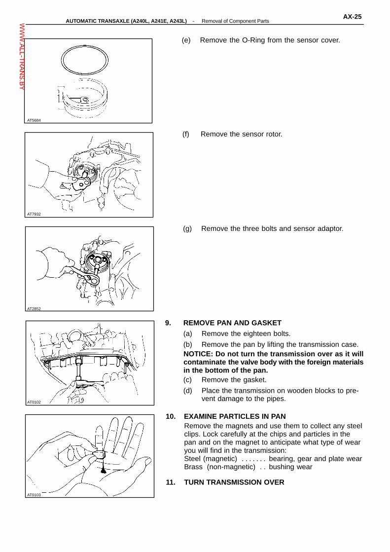
AT0103
AT5684
AT7932
AT0102
AT2852
(e) Remove the O-Ring from the sensor cover.
(f) Remove the sensor rotor.
(g) Remove the three bolts and sensor adaptor.
9. REMOVE PAN AND GASKET(a) Remove the eighteen bolts.
(b) Remove the pan by lifting the transmission case.NOTICE: Do not turn the transmission over as it willcontaminate the valve body with the foreign materialsin the bottom of the pan.(c) Remove the gasket.
(d) Place the transmission on wooden blocks to pre-vent damage to the pipes.
10. EXAMINE PARTICLES IN PANRemove the magnets and use them to collect any steelclips. Lock carefully at the chips and particles in thepan and on the magnet to anticipate what type of wearyou will find in the transmission:Steel (magnetic) bearing, gear and plate wear. . . . . . . Brass (non-magnetic) bushing wear. .
11. TURN TRANSMISSION OVER
-AUTOMATIC TRANSAXLE (A240L, A241E, A243L) Removal of Component PartsAX-25W
WW.ALL-TR
ANS.BY

AT2856
AT2854
AT2855
AT5685
AT5645
12. REMOVE OIL STRAINER(a) Remove the three bolts and oil strainer.
(b) Remove the gasket.
Gasket
13. REMOVE OIL TUBES(a) Remove the two bolts and tube gasket.
(b) Remove the tube clamp bolt and clamp.
(c) Pry up both ends with a large screwdriver andremove the five tubes.
14. REMOVE MANUAL DETENT SPRING
AX-26-AUTOMATIC TRANSAXLE (A240L, A241E, A243L) Removal of Component PartsW
WW.ALL-TR
ANS.BY
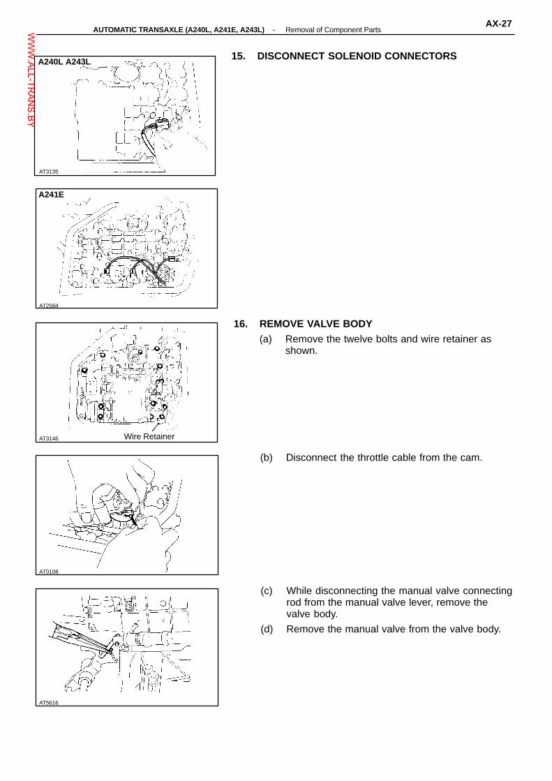
AT2584
AT3146
AT0108
AT5616
AT3135
15. DISCONNECT SOLENOID CONNECTORSA240L A243L
A241E
16. REMOVE VALVE BODY(a) Remove the twelve bolts and wire retainer as
shown.
Wire Retainer
(b) Disconnect the throttle cable from the cam.
(c) While disconnecting the manual valve connectingrod from the manual valve lever, remove thevalve body.
(d) Remove the manual valve from the valve body.
-AUTOMATIC TRANSAXLE (A240L, A241E, A243L) Removal of Component PartsAX-27W
WW.ALL-TR
ANS.BY

AT0507
AT5692
AT1290
AT5642
AT2859
17. REMOVE THROTTLE CABLE FROM CASEPull out the throttle cable.
18. REMOVE SOLENOID WIRE
SolenoidWire
19. REMOVE SECOND BRAKE APPLY GASKET
20. REMOVE SECOND BRAKE DRUM SEALUsing a needle nose pliers, pull out the second brakedrum seal.
21. REMOVE C3 ACCUMULATOR PISTON AND SPRINGUsing low-pressure compressed air (98 kPa, 1 kg/cm2,14 psi), pop out the piston into a rag. Force air into thehole shown and remove the piston and spring.
AX-28-AUTOMATIC TRANSAXLE (A240L, A241E, A243L) Removal of Component PartsW
WW.ALL-TR
ANS.BY
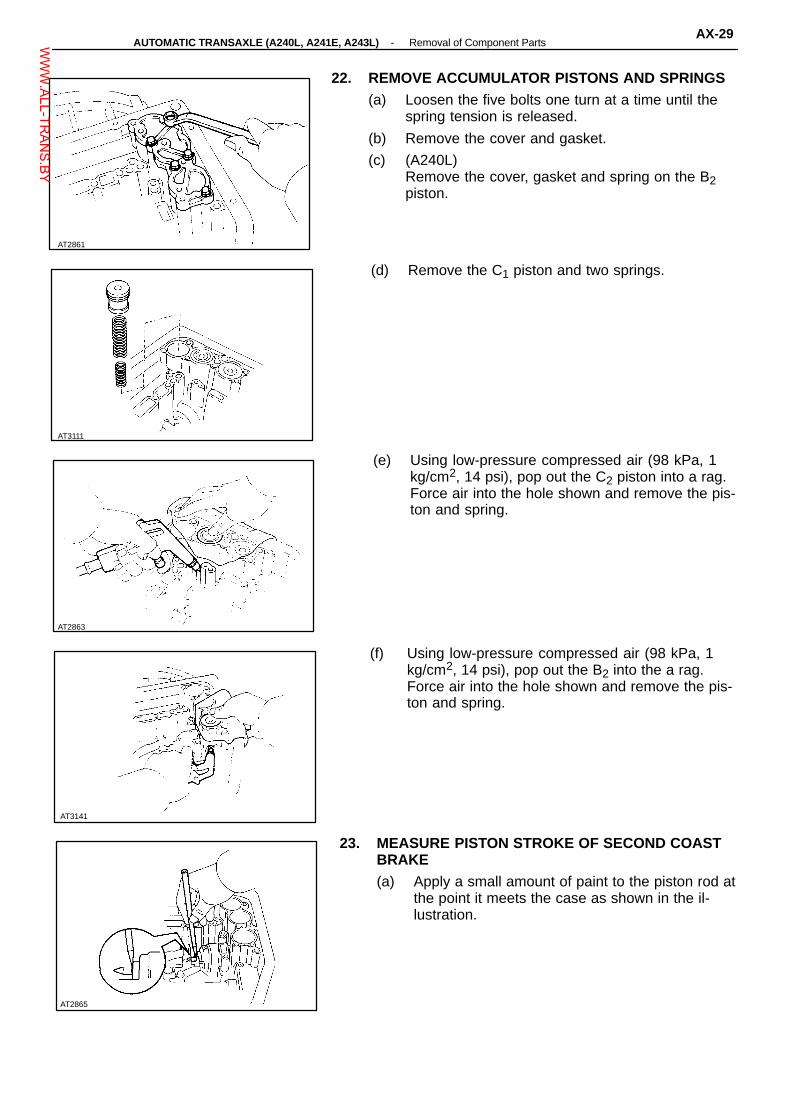
AT3111
AT2863
AT3141
AT2865
AT2861
22. REMOVE ACCUMULATOR PISTONS AND SPRINGS(a) Loosen the five bolts one turn at a time until the
spring tension is released.
(b) Remove the cover and gasket.
(c) (A240L)Remove the cover, gasket and spring on the B2piston.
(d) Remove the C1 piston and two springs.
(e) Using low-pressure compressed air (98 kPa, 1kg/cm2, 14 psi), pop out the C2 piston into a rag.Force air into the hole shown and remove the pis-ton and spring.
(f) Using low-pressure compressed air (98 kPa, 1kg/cm2, 14 psi), pop out the B2 into the a rag.Force air into the hole shown and remove the pis-ton and spring.
23. MEASURE PISTON STROKE OF SECOND COASTBRAKE(a) Apply a small amount of paint to the piston rod at
the point it meets the case as shown in the il-lustration.
-AUTOMATIC TRANSAXLE (A240L, A241E, A243L) Removal of Component PartsAX-29W
WW.ALL-TR
ANS.BY
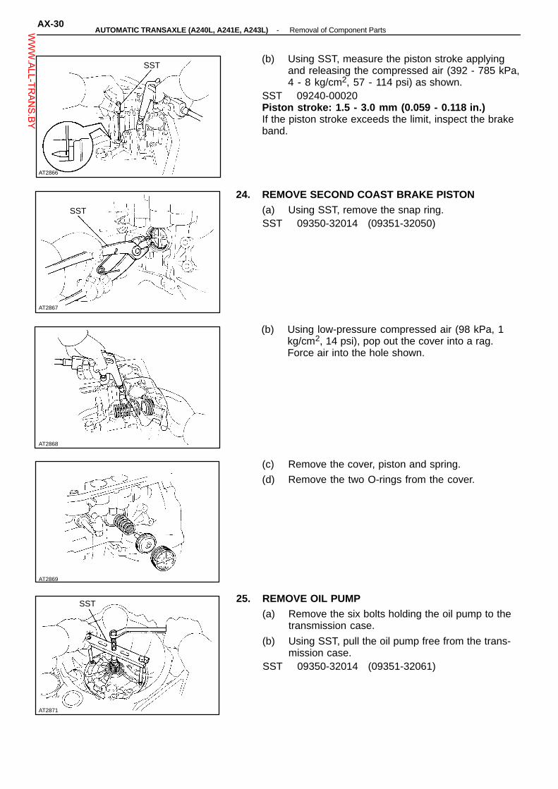
AT2867
AT2868
AT2869
AT2871
SST
AT2866
SST(b) Using SST, measure the piston stroke applying
and releasing the compressed air (392 - 785 kPa,4 - 8 kg/cm2, 57 - 114 psi) as shown.
SST 09240-00020Piston stroke: 1.5 - 3.0 mm (0.059 - 0.118 in.)If the piston stroke exceeds the limit, inspect the brakeband.
24. REMOVE SECOND COAST BRAKE PISTON(a) Using SST, remove the snap ring.SST 09350-32014 (09351-32050)
SST
(b) Using low-pressure compressed air (98 kPa, 1kg/cm2, 14 psi), pop out the cover into a rag.Force air into the hole shown.
(c) Remove the cover, piston and spring.
(d) Remove the two O-rings from the cover.
25. REMOVE OIL PUMP(a) Remove the six bolts holding the oil pump to the
transmission case.
(b) Using SST, pull the oil pump free from the trans-mission case.
SST 09350-32014 (09351-32061)
AX-30-AUTOMATIC TRANSAXLE (A240L, A241E, A243L) Removal of Component PartsW
WW.ALL-TR
ANS.BY
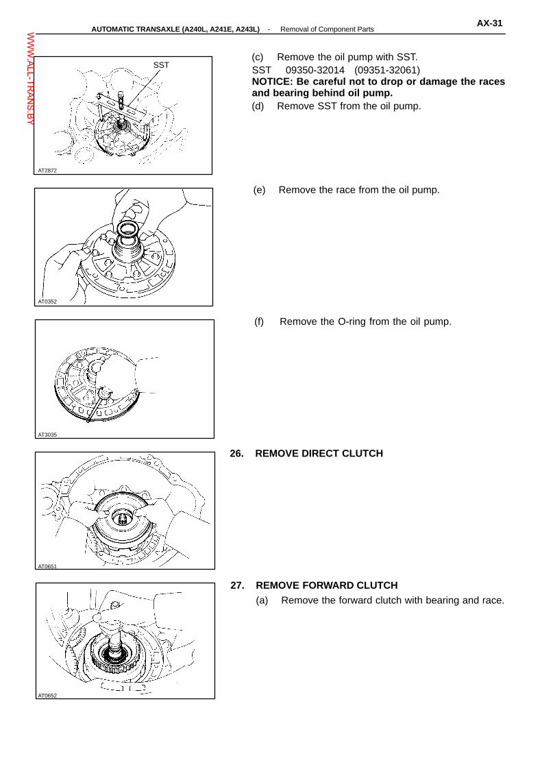
AT2872
SST
AT3035
AT0651
AT0652
AT0352
(c) Remove the oil pump with SST.SST 09350-32014 (09351-32061)NOTICE: Be careful not to drop or damage the racesand bearing behind oil pump.(d) Remove SST from the oil pump.
(e) Remove the race from the oil pump.
(f) Remove the O-ring from the oil pump.
26. REMOVE DIRECT CLUTCH
27. REMOVE FORWARD CLUTCH(a) Remove the forward clutch with bearing and race.
-AUTOMATIC TRANSAXLE (A240L, A241E, A243L) Removal of Component PartsAX-31W
WW.ALL-TR
ANS.BY

AT5618
AT2874
AT5595
AT5644
AT0123 AT0124
(b) Remove the thrust washer, bearings and racesfrom the forward clutch.
28. REMOVE SECOND COAST BRAKE BAND(a) Push the pin with a small screwdriver and remove
it from the bolt hole of the. oil pump mounting.
(b) Remove the brake band.
29. REMOVE FRONT PLANETARY RING GEAR(a) Remove the front planetary ring gear with race.
(b) Remove the races from the ring gear.
30. REMOVE FRONT PLANETARY GEAR(a) Remove the front planetary gear with bearing
and race.
AX-32-AUTOMATIC TRANSAXLE (A240L, A241E, A243L) Removal of Component PartsW
WW.ALL-TR
ANS.BY

AT5596
AT2878
AT7891
AT0519
AT5648
(b) Remove the races and bearings from the plane-tary gear.
31. REMOVE SUN GEAR, SUN GEAR INPUT DRUM ANDTHRUST WASHER
32. REMOVE SECOND BRAKE HUB AND NO. 1 ONE-WAY CLUTCH
33. CONFIRM THAT SECOND BRAKE PISTON MOVESUsing compressed air, confirm that the second brakepiston moves smoothly.
34. REMOVE SECOND COAST BRAKE BAND GUIDE
-AUTOMATIC TRANSAXLE (A240L, A241E, A243L) Removal of Component PartsAX-33W
WW.ALL-TR
ANS.BY

AT2880
AT2881
AT2882
AT2883
AT2879
35. REMOVE SNAP RING HOLDING SECOND BRAKEDRUM TO CASE
36. REMOVE SECOND BRAKE DRUMHINT: If the brake drum is difficult to remove, lightly capit with a wooden block.
37. REMOVE SECOND BRAKE PISTON RETURNSPRING(a) Remove the thrust washer.
(b) Remove the return spring.
38. REMOVE PLATES, DISCS AND FLANGE
39. REMOVE SNAP RING HOLDING NO. 2 ONE-WAYCLUTCH OUTER RACE TO CASEUsing a screwdriver, remove the snap ring.
AX-34-AUTOMATIC TRANSAXLE (A240L, A241E, A243L) Removal of Component PartsW
WW.ALL-TR
ANS.BY
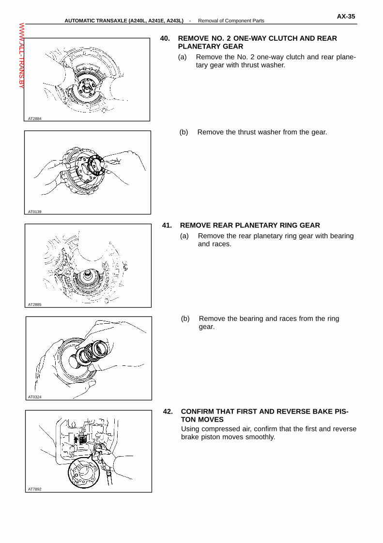
AT0139
AT2885
AT0324
AT7892
AT2884
40. REMOVE NO. 2 ONE-WAY CLUTCH AND REARPLANETARY GEAR(a) Remove the No. 2 one-way clutch and rear plane-
tary gear with thrust washer.
(b) Remove the thrust washer from the gear.
41. REMOVE REAR PLANETARY RING GEAR(a) Remove the rear planetary ring gear with bearing
and races.
(b) Remove the bearing and races from the ringgear.
42. CONFIRM THAT FIRST AND REVERSE BAKE PIS-TON MOVESUsing compressed air, confirm that the first and reversebrake piston moves smoothly.
-AUTOMATIC TRANSAXLE (A240L, A241E, A243L) Removal of Component PartsAX-35W
WW.ALL-TR
ANS.BY

AT2887
AT5653
A241E
AT0521
AT0522
AT2886
43. REMOVE SNAP RING HOLDING FLANGE TO CASEUsing a screwdriver, remove the snap ring.
44. REMOVE FLANGES, PLATES AND DISCS
45. (A241E)REMOVE ENGINE MOUNTING LEFT BRACKET
46. REMOVE TRANSAXLE REAR COVER(a) Remove the thirteen bolts:
(b) Tap off the circumference of the cover with a plas-tic hammer to remove the cover from the trans-mission case, and remove the cover.
AX-36-AUTOMATIC TRANSAXLE (A240L, A241E, A243L) Removal of Component PartsW
WW.ALL-TR
ANS.BY

AT0523
Ex. A240L
AT0525
AT0526
AT2892
47. REMOVE INTERMEDIATE SHAFTRemove the intermediate shaft from the transmissioncase.
48. REMOVE SNAP RINGUsing snap ring pliers, remove the snap ring.
49. REMOVE TRANSAXLE HOUSINGRemove the bolts and transaxle housing.(A241E, A243L) nineteen bolts(A240L) eighteen bolts
AT5682
50. REMOVE DIFFERENTIAL
51. REMOVE GOVERNOR DRIVEN GEAR(a) Remove the governor driven gear.
-AUTOMATIC TRANSAXLE (A240L, A241E, A243L) Removal of Component PartsAX-37W
WW.ALL-TR
ANS.BY

AT0527
AT5602
AT2894 AT2895
AT0529
AT2893
(b) Remove the thrust washer.
52. REMOVE APPLY GASKETS(A240L, A243L)Remove the three gaskets.
(A241E)Remove the two gaskets.
53. REMOVE COUNTER SHAFT LOCK NUTS(a) Using a chisel and hammer, unstake the counter
shaft lock nut on both sides.
(b) Using SST, remove the lock nut of the driven gearside.
SST 09330-00021, 09350-32014 (09351-32032)SST
AX-38-AUTOMATIC TRANSAXLE (A240L, A241E, A243L) Removal of Component PartsW
WW.ALL-TR
ANS.BY

AT0532
AT0533
AT2896
AT0535
AT0530 AT0531
SST (c) Using SST to hold the driven gear, remove thelock nut of the another side.
SST 09330-00021 and09350-32014 (09351-32032, 09351-32170)
SST
54. REMOVE COUNTER DRIVEN GEARUsing SST, remove the driven gear.SST 09350-32014 (09351-32061)
SST
55. REMOVE THRUST NEEDLE BEARING
56. REMOVE COUNTER SHAFT ASSEMBLYPull out the counter shaft assembly.
57. REMOVE THRUST BEARING WITH RACERemove the thrust bearing with race from the countershaft assembly.
-AUTOMATIC TRANSAXLE (A240L, A241E, A243L) Removal of Component PartsAX-39W
WW.ALL-TR
ANS.BY

AT7999
AT2897
AT7889
AT2898
AT8072
58. CHECK PISTON STROKE OF UNDERDRIVECLUTCH(a) Set a dial indicator (long type pick or SST) as
shown.SST 09350-32014 (09351-32190)
(b) Applying and releasing the compressed air (392785 kPa, 4 - 8 kg/cm2, 57 - 114 psi), measure theunderdrive clutch piston stroke.
Piston stroke:A241E 1.21 - 1.55 mm (0.0476 - 0.0610 in.)A2401L, A243L
1.50 - 1.86 mm (0.0591 - 0.0732 in.)If the piston stroke is nonstandard, select anotherflange.HINT: There are two or three different flange thickness.Flange thickness:
A240L 2.04 mm (0.0803 in.)2.40 mm (0.0945 in.)
A241E, A243L 2.30 mm (0.0906 in.)2.50 mm (0.0984 in.)2.70 mm (0.1063 in.)
59. REMOVE UNDERDRIVE CLUTCH DRUM AND ANTI-RATTLE CLIP
60. CONFIRM THAT UNDERDRIVE BRAKE PISTONMOVESUsing compressed air, confirm that the underdrivebrake piston moves smoothly.
61. REMOVE OIL SEAL RINGSRemove the two oil seal rings.
AX-40-AUTOMATIC TRANSAXLE (A240L, A241E, A243L) Removal of Component PartsW
WW.ALL-TR
ANS.BY

AT2899
SST
AT2900
AT2901
AT2902
AT2903
62. REMOVE FLANGE, PLATES AND DISCS(a) Using SST and press, press in the flange until the
snap ring it free from the flange.SST 09350-32014 (09351-32070)(b) Using a screwdriver, remove the snap ring.
(c) Remove the flange, three plates and discs.
63. REMOVE RETURN SPRING
64. REMOVE UNDERDRIVE BRAKE PISTONUsing low-pressure compressed air (88 kPa, 1 kg/cm2,14 psi), pop out the brake piston into a rag. Force airinto the hole shown and remove the brake piston.
65. REMOVE O-RINGS FROM PISTONRemove the two O-rings from the piston.
-AUTOMATIC TRANSAXLE (A240L, A241E, A243L) Removal of Component PartsAX-41W
WW.ALL-TR
ANS.BY

AT0376
SST
AT2888
AT2889
AT2891
AT5656
Snap Ring
68. REMOVE SNAP RING(a) Set SST, and tighten the bolt gradually to com-
press the springs until the snap ring is free fromthe spring seat.
SST 09350-32014 (09351-32040)
Spring Seat
(b) Using snap ring pliers, remove the snap ring.
(c) Remove SST.SST 09350-32013 (09351-32040)
SST
67. REMOVE RETURN SPRINGRemove the return spring and snap ring.
68. REMOVE PISTON FROM TRANSMISSION CASEWITH COMPRESSED AIR(a) Apply compressed air into the oil passage of the
case to remove the piston.HINT: Hold the piston so it is not slanted and blow withthe gun slightly away from the oil hole.(b) If the piston does not pop out with compressed
air, use needle-nose pliers to remove it.
69. REMOVE O-RINGS FROM PISTONRemove the two O-rings from the piston.
AX-42-AUTOMATIC TRANSAXLE (A240L, A241E, A243L) Removal of Component PartsW
WW.ALL-TR
ANS.BY

AT0542
AT0543
AT0544
AT2904
AT0541
70. REMOVE PARKING LOCK PAWL STOPPER PLATE,TORSION SPRING AND SPRING GUIDE
71. REMOVE PAWL SHAFT CLAMPRemove the bolt and pawl shaft clamp.
72. REMOVE PARKING LOCK PAWL SHAFT AND LOCKPAWL
73. REMOVE PARKING LOCK SLEEVE
74. REMOVE CAM GUIDE BRACKETRemove the cam guide bracket as shown.
-AUTOMATIC TRANSAXLE (A240L, A241E, A243L) Removal of Component PartsAX-43W
WW.ALL-TR
ANS.BY

AT2906
AT0547
AT0548
AT2907
AT2905
75. REMOVE MANUAL VALVE SHAFT SPACERUsing a screwdriver and hammer, unstake the spacerand remove it.
76. REMOVE PINUsing a punch and hammer, drive out the pin.
77. REMOVE MANUAL VALVE SHAFT AND LEVER(a) Remove the retaining spring.
(b) Slide out the manual valve shaft and remove themanual valve lever and washer.
78. IF NECESSARY, REPLACE OIL SEAL OF MANUALSHAFT(a) Using a screwdriver, remove the oil seal.
AX-44-AUTOMATIC TRANSAXLE (A240L, A241E, A243L) Removal of Component PartsW
WW.ALL-TR
ANS.BY
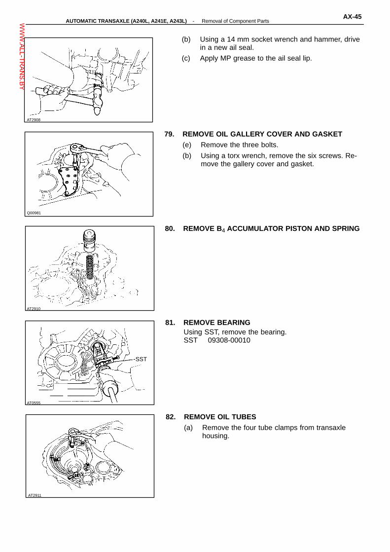
Q00981
AT2910
AT0555
AT2911
AT2908
(b) Using a 14 mm socket wrench and hammer, drivein a new ail seal.
(c) Apply MP grease to the ail seal lip.
79. REMOVE OIL GALLERY COVER AND GASKET(e) Remove the three bolts.
(b) Using a torx wrench, remove the six screws. Re-move the gallery cover and gasket.
80. REMOVE B4 ACCUMULATOR PISTON AND SPRING
81. REMOVE BEARINGUsing SST, remove the bearing.SST 09308-00010
SST
82. REMOVE OIL TUBES(a) Remove the four tube clamps from transaxle
housing.
-AUTOMATIC TRANSAXLE (A240L, A241E, A243L) Removal of Component PartsAX-45W
WW.ALL-TR
ANS.BY

AT2913
AT2915
AT2916
AT2912
(b) Using a screwdriver, remove the three (A241E) orfour (A240L, A243L) oil tubes.
83. REMOVE OIL TUBE APPLY COVER AND GASKETRemove the three bolts, and remove the cover andgasket.
84. REMOVE BEARING(a) Remove the bolt and retainer.
(b) Using SST, remove the bearing.SST 09308-00010
AX-46-AUTOMATIC TRANSAXLE (A240L, A241E, A243L) Removal of Component PartsW
WW.ALL-TR
ANS.BY

INSTALLATION OF COMPONENTPARTS (A241H)
Disassembly, inspection and assembly of each com-ponent group have been indicated in the precedingchapter.Before assembly, make sure again that all compo-nent groups are assembled correctly. If somethingwrong is found in a certain component group duringassembly, inspect and repair this group immediately.Recommended:ATF Type T (08886 - 00405) or equivalentGEAR OIL SUPER or equivalent
ATF Type T (08886 - 00405) orequivalent
GEAR OIL SUPER (08885 - 02106) orequivalent
AT4331
GENERAL ASSEMBLY NOTES:1. The automatic transmission is composed of highly
precision finished parts, necessitating careful in-spection before assembly, because even a smallnick could cause fluid leakage or affect perfor-mance.
2. Before assembling new clutch discs, soak them inautomatic transmission fluid for at least fifteen min-utes.
3. Apply automatic transmission fluid on the sliding orrotating surfaces of parts before assembly.
4. Use petroleum jelly to keep small parts in theirplace.
5. Do not use adhesive cements on gaskets and simi-lar parts.
6. When assembling the transmission, be sure to usenew gaskets and O-rings.
7. Dry all parts by blowing with compressed air. Neveruse shop rags.
-AUTOMATIC TRANSAXLE (A241H) Installation of Component PartsAX-201W
WW.ALL-TR
ANS.BY

8. Be sure to install the thrust bearings and races inthe correct direction and position.
AT2955
AX-202-AUTOMATIC TRANSAXLE (A241H) Installation of Component PartsW
WW.ALL-TR
ANS.BY
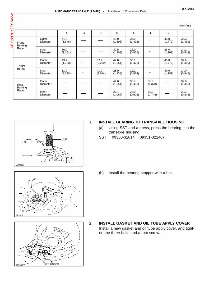
AT3065
AT2915
Torx Screw
A B C D E F G H
FrontBearingRace
OuterDiameter
41.8(1.646)
43.0(1.693)
37.9(1.492) ← 45.0
(1.772)37.3(1.469)
InnerDiameter
30.0(1.181)
30.5(1.201)
22.0(0.866) ← 28.0
(1.102)24.1(0.949)
ThrustBering
OuterDiameter
43.7(1.720) ← 57.7
(2.272)42.0(1.654)
36.1(1.421) ← 45.0
(1.772)37.6(1.480)
InnerDiameter
31.0(1.220) ← 41.0
(1.614)28.9(1.138)
22.2(0.874) ← 30.0
(1.181)24.0(0.945)
RearBearingRace
OuterDiameter
42.0(1.654)
35.7(1.406)
35.0(1.378)
37.6(1.480)
InnerDiameter
27.1(1.067)
23.0(0.906)
19.0(0.748)
22.2(0.874)
mm (in.)
1. INSTALL BEARING TO TRANSAXLE HOUSING(a) Using SST and a press, press the bearing into the
transaxle housing.SST 09350-32014 (09351-32140)SST
(b) Install the bearing stopper with a bolt.
2. INSTALL GASKET AND OIL TUBE APPLY COVERInstall a new gasket and oil tube apply cover, and tight-en the three bolts and a torx screw.
AT3343
-AUTOMATIC TRANSAXLE (A241H) Installation of Component PartsAX-203W
WW.ALL-TR
ANS.BY

AT3346
AT3347
AT8073
AT2910
AT0593
3. INSTALL OIL TUBES(a) Using a plastic hammer, install the four oil tubes.NOTICE: Be careful not to bend or damage the tubes.
(b) Using a torx wrench, install the four tube clamps.
TorxWrench
4. INSTALL APPLY GASKETInstall a new apply gasket to the transaxle housing.
5. INSTALL BEARING TO TRANSMISSION CASEUsing SST and a press, press the bearing into thetransmission case.SST 09350-32014 (09351-32090)
SST
6. INSTALL B 4 ACCUMULATOR PISTON AND SPRING
AX-204-AUTOMATIC TRANSAXLE (A241H) Installation of Component PartsW
WW.ALL-TR
ANS.BY

AT5643
AT0548
AT0547
AT2959
AT5696
7. INSTALL OIL GALLERY COVER AND GASKET(a) Clean the threads of the screws and case with
white gasoline.
(b) Install a new gasket and oil gallery cover in place.
(c) Install and tighten the three bolts.
(d) Apply seal packing or equivalent to the six torxscrews.
Seal packing: Part No. 08833 - 00070, THREE BOND1324 or equivalent(e) Install and tighten the six torx screws.
TorxWrench
8. INSTALL MANUAL VALVE SHAFT AND LEVER(a) Install the parking lock rod to the manual valve
lever.
(b) Slide in the shaft and install the washer, newspacer and manual lever.
(c) Install the retaining spring.HINT: Make sure there is a washer between the retain-ing spring and case.
9. INSTALL PIN(a) Using a punch and hammer, drive in the pin.
(b) Position the spacer and stake it.
-AUTOMATIC TRANSAXLE (A241H) Installation of Component PartsAX-205W
WW.ALL-TR
ANS.BY

AT0544
AT8097
AT8095
AT8052
AT0545
10. INSTALL CAM GUIDE BRACKETInstall the cam guide bracket and then insert the park-ing lock rod into the guide bracket.
11. INSTALL PARKING LOCK SLEEVEInstall the parking lock sleeve protruding portion up-ward.
12. INSTALL PARKING LOCK PAWL, PAWL SHAFT ANDSHAFT CLAMP(a) Install the parking lock pawl and pawl shaft.
(b) Align the pawl shaft groove and shaft clamp cutposition.
(c) Install the shaft clamp.
13. INSTALL STOPPER PLATE AND GUIDE SLEEVE(a) Place the stopper plate on the protruding portion
of lock sleeve.
(b) Install the guide sleeve and spring.Torque: 7.4 N-m (75 kgf-cm, 65 in.-Ibf)
AX-206-AUTOMATIC TRANSAXLE (A241H) Installation of Component PartsW
WW.ALL-TR
ANS.BY

AT2960
AT2961
AT2901
AT2900
SST
14. INSTALL UNDERDRIVE BRAKE PISTON(a) Coat two new O-rings with ATF.
(b) Install O-rings to the piston.
(c) Place the piston into the case with the cup sideup, being careful not to damage O-rings.
15. INSTALL RETURN SPRING
16. INSTALL PLATES, DISCS AND FLANGE(a) Install in order: D = Disc P = Plate F = Flange
P-D-P-D-P-D-FHINT: Install the flange with the flat end facing upward.
(b) Place SST on the flange, and compress theflange with a press.
SST 09350-32014 (09351-32070)(c) Install the snap ring.HINT: Be sure the end gap of the snap ring is notaligned with one of the cutouts.
AT2899
-AUTOMATIC TRANSAXLE (A241H) Installation of Component PartsAX-207W
WW.ALL-TR
ANS.BY

AT2898
AT1292
AT1289
AT0597
Free
AT7889
17. CONFIRM THAT UNDERDRIVE BRAKE PISTONMOVESUsing compressed air, confirm that the underdrivebrake piston moves smoothly.
18. INSTALL OIL SEAL RINGS To TRANSMISSIONCASEInstall the two oil seals to the transmission case.
19. INSTALL UNDERDRIVE ONE-WAY CLUTCH
20. INSTALL ANTI-RATTLE CLIPIn the place shown in the figure (the space between theone-way clutch outer race and case), push the anti-rattle clip in until you hear the ”click”.
Lock
21. INSTALL UNDERDRIVE CLUTCH ASSEMBLY(a) Align the flukes of discs in the underdrive brake.
(b) Install the clutch assembly.
(c) Turn the clutch assembly. The clutch assemblyshould turn freely counterclockwise and shouldlock clockwise.
AX-208-AUTOMATIC TRANSAXLE (A241H) Installation of Component PartsW
WW.ALL-TR
ANS.BY

AT7987
AT8072
AT7999
AT1293
22. CHECK HEIGHT OF CLUTCH ASSEMBLYUsing vernier calipers, check the height from the sleeveto the inner race.Height: 17.3 - 18.2 mm (0.6811 - 0.7165 in.)
17.3 - 18.2 mm
23. CHECK PISTON STROKE OF UNDERDRIVE CLUTCH(a) Set a dial indicator (long type pick or SST) as
shown.SST 09350-32014 (09351-32190)SST
(b) Applying and releasing the compressed air (392 -785 kPa, 4 - 8 kg/cm2, 57 - 114 psi), measurethe underdrive clutch piston stroke.
Piston stroke: 1.50 - 1.86 mm (0.0591 - 0.0732 in.)If the piston stroke is less than limit, parts may havebeen misassembled. Check them.If the piston stroke is nonstandard, select anotherflange.HINT: There are two different flange thickness.Flange thickness: 2.04 mm (0.0803 in.)
2.40 mm (0.0945 in.)
24. INSTALL BEARING WITH RACEInstall the thrust bearing with race, with the bearing fac-ing upward.Bearing: Outer diameter 43.7 mm (1.720 in.)
Inner diameter 31.0 mm (1.220 in.)
25. INSTALL SUN GEAR To CASEInstall the sun gear of the counter shaft to the case.
AT1294
-AUTOMATIC TRANSAXLE (A241H) Installation of Component PartsAX-209W
WW.ALL-TR
ANS.BY

AT7988
AT0533
AT8084
AT0603
SST
AT2896
26. INSTALL COUNTER SHAFT ASSEMBLY(a) Align the flukes of the discs in the underdrive
clutch.
(b) Install the counter shaft assembly.
27. CHECK HEIGHT OF COUNTER SHAFTUsing vernier calipers, measure the distance betweenthe tip of the counter shaft and bolt seat of the clutchsupport.Height: 33.3 - 35.5 mm (1.311 - 1.398 in.)
28. INSTALL THRUST NEEDLE BEARINGBearing: Outer diameter 57.7 mm (2.272 in.)
Inner diameter 41.0 mm (1.614 in.)
29. INSTALL COUNTER DRIVEN GEARUsing SST and press, press in the driven gear.SST 09350-32014 (09351-32100, 09351-32140)
SST
30. TIGHTEN NEW LOCK NUT(a) Using SST to hold the driven gear, tighten a new
lock nut.SST 09330-00021, 09350-32014 (09351-32032)Torque: 157 N-m (1,600 kgf-cm, 116 ft-lbf)(b) Remove SST.
AX-210-AUTOMATIC TRANSAXLE (A241H) Installation of Component PartsW
WW.ALL-TR
ANS.BY

AT2962
AT2963
AT0076
AT8483
AT0604
31. CHECK END PLAY OF COUNTER SHAFTUsing a dial indicator, measure the end play of thecounter shaft.End play: 0.23 - 0.89 mm (0.0091 - 0.0350 in.)
32. STAKE LOCK NUTUsing a punch and hammer, stake the lock nut.
33. INSTALL FIRST AND REVERSE BRAKE PISTON(a) Coat the two new O-rings with ATF.
(b) Install two O-rings to piston.
(c) Place the piston into the bore of the case, facingthe spring seats upward.
(d) Using SST, press into the piston.SST 09350-32014 (09351-32040)HINT: Be careful not to damage the O-rings.(e) Remove SST.
SST
34. INSTALL PISTON RETURN SPRING AND SNAPRING(a) Install the piston return spring assembly and snap
ring in place.
(b) Set SST, and tighten the bolt gradually to com-press the springs.
SST 09350-32014 (09351-32040)NOTICE: Avoid bending the spring retainer by over-tightening the bolt.
SST
-AUTOMATIC TRANSAXLE (A241H) Installation of Component PartsAX-21 1W
WW.ALL-TR
ANS.BY

AT7911
AT8094
AT2888
AT2892
AT0523
(c) Using snap ring pliers, install the snap ring.HINT: Visually check to make sure it is fully seated andcentered by the three lugs on the spring retainer.Be sure the end gap of snap ring is not aligned with thespring retainer claw.(d) Remove SST.SST 09350-32014 (09351-32040)
SST
35. INSTALL SNAP RING TO TRANSMISSION CASEUsing snap ring pliers, install the snap ring to the trans-mission case.
36. INSTALL INTERMEDIATE SHAFT
37. INSTALL TRANSAXLE REAR COVER(a) Remove any packing material and be careful not to
get oil on the contacting surfaces of the transaxlerear cover or transmission case.
(b) Apply seal packing to the rear cover as shown.Seal packing: Part No. 08833 - 00090, THREE BOND
1131, LOCTITE 518 or equivalent
Seal Packing
(c) Install and tighten the thirteen bolts.Torque: 29 N-m (300 kgf-cm, 22 ft-lbf)HINT: Each bolt length (mm) is indicated in the figure.
AX-212-AUTOMATIC TRANSAXLE (A241H) Installation of Component PartsW
WW.ALL-TR
ANS.BY

AT0607
AT0527
AT0526
AT0606
AT2893
38. INSTALL NEW APPLY GASKETSInstall the three new apply gaskets.HINT: The apply gasket may be inserted with either endup or down.
39. INSTALL GOVERNOR DRIVEN GEAR(a) Install the thrust washer.
(b) Install the governor driven gear.
40. CHECK INTERMEDIATE SHAFTMake sure that the intermediate shaft turns smoothly.
41. INSTALL FIRST AND REVERSE BRAKE DISCS,PLATES AND FLANGE(a) Install the inner flange, facing the flat end upward.
-AUTOMATIC TRANSAXLE (A241H) Installation of Component PartsAX-213W
WW.ALL-TR
ANS.BY

AT0610
AT7892
AT0324
AT3501
Outer diameter Inner diameter
Front Race 27.3 (1.469) 24.1 (0.949)
Bearing 37.6 (1.480) 24.0 (0.945)
Rear Race 37.6 (1.480) 22.0 (0.874)
AT3500
Bearing and races mm (in.)
(b) Install in order: D = Disc P = PlateD-P-D-P-D-P-D-P-D-P-D
(c) Install the outer flange, the flat end facing down-ward.
42. INSTALL SNAP RINGHINT: Be sure the snap ring end gap is not aligned withone of the cutouts.
43. CONFIRM THAT FIRST AND REVERSE BRAKE PIS-TON MOVESUsing compressed air, confirm that the first and reversebrake piston moves smoothly.
44. INSTALL REAR PLANETARY RING GEAR TO CASE(a) Coat the races and bearing with petroleum jelly, ,
and install them onto the ring gear as shown.
AX-214-AUTOMATIC TRANSAXLE (A241H) Installation of Component PartsW
WW.ALL-TR
ANS.BY

AT0612
AT0323
AT0614
AT2965
AT0613
(b) Using a screwdriver, align the flukes of the discs.
(c) Install the rear planetary ring gear into the case.
45. INSTALL REAR PLANETARY GEAR(a) Coat thrust washer with petroleum jelly and install
it onto the planetary gear.HINT: Make sure that the different lug shapes match theopenings on the gear.
(b) Align the spline of the planetary gear with theflukes of the discs and install the planetary gearinto the first and reverse brake discs.
46. INSTALL NO. 2 ONE-WAY CLUTCH(a) Place the one-way clutch into the case, the shiny
side facing upward.
(b) Install the one-way clutch onto the inner racewhile turning the planetary gear clockwise withSST.
SST 09350-32014 (09351-32050)SST
Align
-AUTOMATIC TRANSAXLE (A241H) Installation of Component PartsAX-215W
WW.ALL-TR
ANS.BY

AT0519
AT2966
AT0617
AT0618
AT0616
Free
(c) Coat the thrust washer with petroleum jelly andinstall it onto the planetary gear.
47. CHECK OPERATION OF NO. 2 ONE-WAY CLUTCHCheck that the planetary carrier turns freely clockwiseand locks counterclockwise.
Lock
48. INSTALL SNAP RINGBe sure the end gap of the snap ring is not aligned withone of the cutouts.
49. INSTALL SECOND COAST BRAKE BAND GUIDEInstall the band guide so that its tip touches the case.
50. INSTALL SECOND BRAKE INTO CASE(a) Install the flange, the flat side facing upward.
AX-216-AUTOMATIC TRANSAXLE (A241H) Installation of Component PartsW
WW.ALL-TR
ANS.BY

AT0620
AT0621
AT0622
AT2592
AT2967
(b) Install the discs and plates in order.D = Disc P = PlateD-P-D-P-D-P
51. INSTALL SECOND BRAKE PISTON RETURNSPRINGInstall each of the springs over the protrusions in thecase.
52. INSTILL SECOND BRAKE DRUM INTO CASEAlign the groove of the drum with the bolt and place itinto the case.
53. INSTALL SNAP RING(a) Place the snap ring into the case so that the end
gap is installed into the groove.
(b) While compressing the piston return springs overthe drum with hammer handles, install the snapring.
HINT: Be sure the end gap of the snap ring is notaligned with one of the cutouts.
54. INSTALL SECOND BRAKE DRUM GASKETDrive in a new drum gasket until it makes contact withthe second brake drum.
-AUTOMATIC TRANSAXLE (A241H) Installation of Component PartsAX-217W
WW.ALL-TR
ANS.BY

AT7891
AT0626
AT0627
AT0828
AT5720
55. CONFIRM THAT SECOND BRAKE PISTON MOVESUsing compressed air, confirm that the second brakepiston moves smoothly.
56. INSTALL SECOND BRAKE HUB AND No. 1 ONE-WAY CLUTCH(a) Using a screwdriver, align the flukes of the discs
in the second brake.
(b) Align the spline of the hub with the flukes of thediscs and install the hub to the second brakediscs.
57. CHECK SECOND BRAKE HUB INSTALLATION DIS-TANCECheck the distance between the surface of the secondbrake hub and rear planetary gear.Distance: Approx. 5 mm (0.20 in.)
58. INSTALL SUN GEAR, SUN GEAR INPUT DRUM ANDTHRUST WASHERWhile turning the sun gear clockwise, install it into theone-way clutch.
AX-218-AUTOMATIC TRANSAXLE (A241H) Installation of Component PartsW
WW.ALL-TR
ANS.BY

AT2759
AT0631
Outer diameter Inner diameter
Front Race 37.9 (1.492) 22.0 (0.866)
Bearing 36.1 (1.421) 22.2 (0.874)
Rear Race 35.0 (1.378) 19.0 (0.748)AT2593
AT2868
Outer diameter Inner diameter
Race 45.0 (1.772) 28.0 (1.102)
Bearing 45.0 (1.772) 30.0 (1.181)
Bearing and races mm (in.)
Bearing and races mm (in.)
59. INSTALL FRONT PLANETARY GEAR(a) Coat the race and bearing with petroleum jelly and
install them onto the planetary gear.
(b) Install the planetary gear.
60. INSTALL FRONT PLANETARY RING GEAR(a) Coat the races and bearing with petroleum jelly
and install them onto the planetary ring gear.
(b) Install the ring gear.
HINT: If the planetary ring gear and the other parts areinstalled correctly into the case, the end of the bushingwith the ring gear flange will be flush with a shoulder ofthe intermediate shaft or under.
AT2023
-AUTOMATIC TRANSAXLE (A241H) Installation of Component PartsAX-219W
WW.ALL-TR
ANS.BY
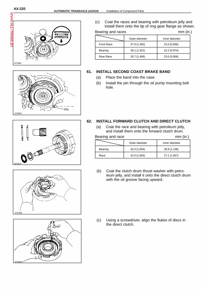
Outer diameter Inner diameter
Front Race 37.9 (1.492) 22.0 (0.866)
Bearing 36.1 (1.421) 22.2 (0.874)
Rear Race 35.7 (1.406) 23.0 (0.906)
AT0635
Outer diameter Inner diameter
Bearing 42.0 (1.654) 28.9 (1.138)
Race 42.0 (1.654) 27.1 (1.067)
AT2970
AT0349
AT0350
AT2969
Bearing and race
Bearing and races mm (in.)
(c) Coat the races and bearing with petroleum jelly andinstall them onto the tip of ring gear flange as shown.
61. INSTALL SECOND COAST BRAKE BAND(a) Place the band into the case.
(b) Install the pin through the oil pump mounting bolthole.
Pin
62. INSTALL FORWARD CLUTCH AND DIRECT CLUTCH(a) Coat the race and bearing with petroleum jelly,
and install them onto the forward clutch drum.
(b) Coat the clutch drum thrust washer with petro-leum jelly, and install it onto the direct clutch drumwith the oil groove facing upward.
(c) Using a screwdriver, align the flukes of discs inthe direct clutch.
mm (in.)
AX-220-AUTOMATIC TRANSAXLE (A241H) Installation of Component PartsW
WW.ALL-TR
ANS.BY

AT1984 AT0381
Bushing
AT2971
AT2595
AT3348
AT3459
(d) Mesh the hub with the flukes of the direct clutchwhile turning the clutch drum or forward clutch.
HINT: If the flukes of the discs are meshed with the hubcorrectly, the end of the bushing with the direct clutchdrum will be flush with the surface of the forward clutch.
Thrust Washer
(e) Place the direct clutch and forward clutch into thecase.
(f) While rotating the forward clutch to mesh the frontplanetary ring gear and discs, install them.
(g) Check the distance between A and B as shown inthe illustration.
Distance: Approx. 3 mm (0.118 in.)
63. INSTALL DIFFERENTIAL ASSEMBLY
SealPacking
64. INSTALL TRANSAXLE HOUSING(a) Remove any packing material and be careful not to
get oil on the contacting surfaces, of the transaxlehousing or transmission case.
(b) Apply seal packing to the transaxle housing asshown.
Seal packing: Part No. 08833 - 00090, THREE BOND1131, LOCTITE 518 or equivalent
HINT: Install the transaxle housing as soon as the sealpacking is applied:
-AUTOMATIC TRANSAXLE (A241H) Installation of Component PartsAX-221W
WW.ALL-TR
ANS.BY

AT8076
AT8048
AT2766
AT0637
AT2972
(c) Apply sealant to the bolt threads.Sealant: Part No. 08833 - 00080, Adhesive 1344,
THREE BOND 1344. LOCTITE 242 orequivalent
(d) Install and tighten the bolts.Torque: 29 N-m (300 kgf-cm, 22 ft-lbf)HINT: Each bolt length (mm) is indicated in the illustra-tion.
65. INSTALL OIL SEAL RINGS
66. INSTALL OIL PUMP INTO CASE(a) Coat the race with petroleum jelly and install it
onto the stator shaft.Race: Outer diameter 43.0 mm (1.693 in.)
Inner diameter 30.5 mm (1.201 in.)
(b) Coat the O-ring with ATF, and install it to pumpbody.
(c) Place the oil pump through the input shaft, andalign the bolt holes of the pump body with thetransmission case.
(d) Hold the input shaft, and lightly press the oil pumpbody to slide the oil seal rings on the stator shaftthrough the direct clutch drum.
NOTICE: Do not push on the oil pump strongly, or theoil seal ring will stick to the direct clutch drum.(e) Install and tighten the six bolts.Torque: 25 N-m (250 kgf-cm, 18 ft-lbf)
AX-222-AUTOMATIC TRANSAXLE (A241H) Installation of Component PartsW
WW.ALL-TR
ANS.BY

AT3345
AT2870
AT2869
AT2867
SST
AT8047
67. MEASURE THRUST PLAY OF INPUT SHAFTMeasure the thrust play in axial direction.Thrust play: 0.3 - 0.9 mm (0.012 - 0.035 in.)If the play is not as specified, select and replace therace for the end of the stator shaft.HINT: There are two different thickness of races.If necessary, select one of them.Race thickness: 0.8 mm (0.031 in.)
1.4 mm (0.055 in.)
68. CHECK INPUT SHAFT ROTATIONMake sure that the input shaft rotates smoothly.
69. INSTALL SECOND COAST BRAKE PISTON(a) Install the two new O-rings to the cover.HINT: Coat the O-rings with ATF before installing.
O-Ring
(b) Install the spring, piston and cover into the bore.
(c) Using SST, install the snap ring while pressingthe cover.
SST 09350-32014 (09351-32050)(d) Check that the front end of the piston rod con-
tacts the center of the second brake band de-pression.
-AUTOMATIC TRANSAXLE (A241H) Installation of Component PartsAX-223W
WW.ALL-TR
ANS.BY

AT2865
AT2866
SST
Spring Free length mm (in.) Color
C1
Outer 78.2 (3.079) Yellow
Inner 41.0 (1.614) Pink
C2 66.2 (2.606) Blue
B2
No. 1 36.5 (1.437) White
No. 2 56.7 (2.232) Yellow
C3 62.1 (2.445) Light Green
AT3225C1
InnerC3
Outer
AT1290
AT3036
No. 1 Spring(B2)
70. MEASURE PISTON STROKE OF SECOND COASTBRAKE(a) Apply a small amount of paint to the piston rod at
the point it meets the case as shown in the il-lustration.
(b) Using SST, measure the piston stroke applyingand releasing the compressed air (392 - 785 kPa,4 - 8 kg/cm2, 57 - 114 psi) as shown.
SST 09240-00020Piston stroke: 1.5 - 3.0 mm (0.059 - 0.118 in.)If it is still more than standard value, replace the brakeband with a new one.
71. INSTALL ACCUMULATOR PISTONS AND SPRINGS(a) Coat the new O-rings with ATF, and install them
to the pistons.
(b) Install the pistons and springs.
No. 2
B2
No. 1 C2
(c) install a new gasket and accumulator cover.
(d) Tighten the five bolts shown in the illustrationevenly and gradually.
72. INSTALL SECOND BRAKE APPLY GASKET
AX-224-AUTOMATIC TRANSAXLE (A241H) Installation of Component PartsW
WW.ALL-TR
ANS.BY

AT3114
AT0108
AT0645
AT3433
AT0643
73. INSTALL THROTTLE CABLE IN CASEPush the cable through the hole on the case, beingcareful not to damage the O-ring. Check for full seating.NOTICE: In subsequent work, to avoid breaking thecable fitting do not roll the case over the cable.
74. INSTALL O/D SOLENOID WIRE
75. INSTALL VALVE BODY(a) Pace the valve body on the transmission.
(b) While holding the cam down with your hand, slipthe cable end into the slot.
(c) Connect the connecting rod to the manual valvelever.
(d) lower the valve body in place.
(e) Install the twelve bolts and wire retainer shown inthe illustration, and hand tighten all the bolts first.Then tighten them with a torque wrench.
HINT: Each bolt length (mm) is indicated in the illustra-tion.Torque: 10 N-m (100 kgf-cm, 7 ft-lbf)
Clamp
-AUTOMATIC TRANSAXLE (A241H) Installation of Component PartsAX-225W
WW.ALL-TR
ANS.BY

AT2854
AT3135
AT0653
AT3431
AT3430
76. CONNECT O/D SOLENOID CONNECTOR
77. INSTALL MANUAL DETENT SPRING(a) Install the detent spring and cover in place, and
install the bolt (length: 16 mm).
(b) Hand tighten the bolt first, then tighten the boltwith a torque wrench.
Torque: 10 N-m (100 kgf-cm, 7 ft-lbf)(c) Check that the manual valve lever is in contact
with the center of the roller at the tip of the detentspring.
78. INSTALL OIL TUBES(a) Tap the tubes with a plastic hammer to install
them into the positions indicated in the illustration.NOTICE: Be careful not to bend or damage the tubes.
(b) Install the oil tube clamp and bracket.HINT: Each bolt length (mm) is indicated in the illustra-tion. Hand tighten all bolts first, then tighten them with atorque wrench.Torque: 10 N-m (100 kgf-cm, 7 ft-lbf)
79. INSTALL OIL STRAINER(a) Install a new gasket to the oil strainer.Gasket
AX-226-AUTOMATIC TRANSAXLE (A241H) Installation of Component PartsW
WW.ALL-TR
ANS.BY

AT5645
AT3440
AT8499
AT8057
AT7992
(b) Install the oil strainer with the three bolts.HINT: Each bolt length (mm) is indicated in the illustra-tion.
80. INSTALL FIVE MAGNETS IN OIL PANNOTICE: Make sure that the magnets do not interferewith the oil tubes.
81. INSTALL OIL PAN(a) Install a new gasket to the oil pan and install them
to the transmission.
(b) Tighten the eighteen bolts.Torque: 4.9 N-m (50 kgf-cm, 43 in.-lbf)
(c) Install a new gasket to the drain plug and install itto the oil pan.
Torque: 17 N-m (175 kgf-cm, 13 ft-lbf)
82. INSTALL GOVERNOR BODY(a) Install the oil strainer.
-AUTOMATIC TRANSAXLE (A241H) Installation of Component PartsAX-227W
WW.ALL-TR
ANS.BY

AT8051
AT8071
AT2850
AT0502
AT8053
(b) Install a new gasket to governor body adaptor.
(c) Install the governor body adaptor with threebolts.
(d) Install the governor body and thrust washer.
(e) Install a new O-ring to the cover.
O-Ring
(f) Install the cover to the transmission and theninstall the two cover brackets with the two bolts.
83. INSTALL SOLENOID WIRE RETAINING PLATEInstall the retaining plate with the bolt.
AX-228-AUTOMATIC TRANSAXLE (A241H) Installation of Component PartsW
WW.ALL-TR
ANS.BY

AT8040
AT8006
AT7762
NeutralBasicLine
AT8041
AT0501
84. INSTALL THROTTLE CABLE RETAINING PLATEInstall the retaining plate with bolt.
85. INSTALL NEUTRAL START SWITCH(a) Install the neutral start switch to the manual valve
shaft.
(b) Install the packing, nut stopper and nut.
(c) Tighten the nut.Torque: 6.9 N-m (70 kgf-cm, 61 in.-lbf)
(d) Temporarily install the manual shift lever.
(e) Turn the lever clockwise until it stops, then turn itcounterclockwise three notches.
(f) Remove the manual shift lever.
(g) Align the groove and neutral basic line as shown.
(h) Install and tighten the two bolts.Torque: 5.4 N-m (55 kgf-cm, 48 in.-lbf)
Groove
(i) Using a screwdriver, stake the nut with the nutstopper.
-AUTOMATIC TRANSAXLE (A241H) Installation of Component PartsAX-229W
WW.ALL-TR
ANS.BY
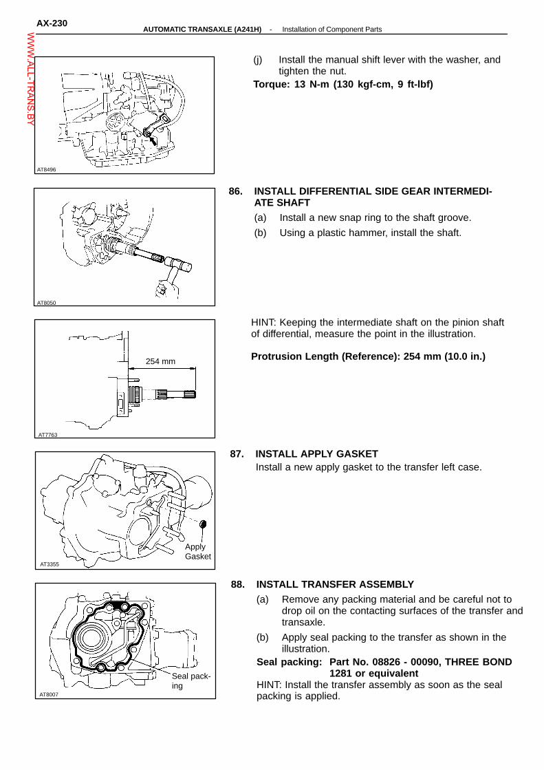
AT8050
AT7763
AT3355
AT8007
AT8496
(j) Install the manual shift lever with the washer, andtighten the nut.
Torque: 13 N-m (130 kgf-cm, 9 ft-lbf)
86. INSTALL DIFFERENTIAL SIDE GEAR INTERMEDI-ATE SHAFT(a) Install a new snap ring to the shaft groove.
(b) Using a plastic hammer, install the shaft.
HINT: Keeping the intermediate shaft on the pinion shaftof differential, measure the point in the illustration.
Protrusion Length (Reference): 254 mm (10.0 in.)254 mm
87. INSTALL APPLY GASKETInstall a new apply gasket to the transfer left case.
ApplyGasket
88. INSTALL TRANSFER ASSEMBLY(a) Remove any packing material and be careful not to
drop oil on the contacting surfaces of the transfer andtransaxle.
(b) Apply seal packing to the transfer as shown in theillustration.
Seal packing: Part No. 08826 - 00090, THREE BOND1281 or equivalent
HINT: Install the transfer assembly as soon as the sealpacking is applied.
Seal pack-ing
AX-230-AUTOMATIC TRANSAXLE (A241H) Installation of Component PartsW
WW.ALL-TR
ANS.BY

AT8074
Free
Mode SelectLever
(c) Install and torque the six nuts.Torque: 69 N-m (700 kgf-cm, 51 ft-lbf)
89. INSPECT MODE SELECT LEVER POSITIONAfter finishing inspection or repair the transaxle, be surethe mode select lever position to FREE mode and at-tach the lock bolt.
Lock
AT3447
-AUTOMATIC TRANSAXLE (A241H) Installation of Component PartsAX-231W
WW.ALL-TR
ANS.BY

COMPONENT PARTSGeneral NotesThe instructions here are organized so that you work on only one component group at a time.This will help avoid confusion from similar-locking parts of different subassemblies being on your work-bench at the same time.The component groups are inspected and repaired from the converter housing side.As much as possible, complete the inspection, repair and assembly before proceeding to the next com-ponent group. If a component group can not be assembled because parts are being ordered, be sure tokeep all parts of that group in a separate container while proceeding with disassembly, inspection, repairand assembly for other component groups.
GENERAL CLEANING NOTES:
1. All disassembled parts should be washed clean with any fluid passages and holes blownthrough with compressed air.
2. When using compressed air to dry parts, always aim away from yourself to prevent acciden-tally spraying automatic transmission fluid or kerosene in your face.
3. The recommended automatic transmission fluid kerosene should be used for cleaning.
PARTS ARRANGEMENT:
1. After cleaning, the parts should be arranged in proper order to allow efficient inspection,repairs, and reassembly.
2. When disassembling a valve body, be sure to keep each value together with the corre-sponding spring.
3. New brakes and clutches that are to be used for replacement must be soaked in transmis-sion fluid for at least fifteen minutes before assembly.
GENERAL ASSEMBLY:
1. All oil seal rings, clutch discs, clutch plates, rotating parts, and sliding surfaces should becoated with transmission fluid prior to reassembly.
2. All gaskets and rubber O-rings should be replaced.3. Make sure that the ends of a snap ring are not aligned with one of the cutouts and are
installed in the groove correctly.4. If a worn bushing is to be replaced, the subassembly containing that bushing must be re-
placed.5. Check thrust bearings and races for wear or damage. Replace if necessary.6. Use petroleum jelly to keep parts in place.
-AUTOMATIC TRANSAXLE Component Parts (General Notes)AX-47W
WW.ALL-TR
ANS.BY
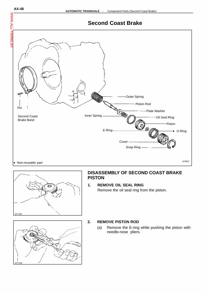
AT7703
♦ Non-reusable part
Snap Ring
♦ O-Ring
Piston
Oil Seal Ring
Plate Washer
Piston Rod
AT7702
Second Coast Brake
Outer Spring
Pin
Inner SpringSecond CoastBrake Band
E-Ring
Cover
AT5657
DISASSEMBLY OF SECOND COAST BRAKEPISTON
1. REMOVE OIL SEAL RINGRemove the oil seal ring from the piston.
2. REMOVE PISTON ROD(a) Remove the E-ring while pushing the piston with
needle-nose pliers.
AX-48-AUTOMATIC TRANSAXLE Component Parts (Second Coast Brake)W
WW.ALL-TR
ANS.BY

AT8098
Printed Number
AT7705
AT7704
AT7706
AT7704
(b) Remove the spring, washer and piston rod.
INSPECTION OF SECOND COAST BRAKECOMPONENT
INSPECT BRAKE BANDIf the lining of the brake band is exfoliated or discol-ored, or even part of the printed numbers are defaced,replace the brake band.
ASSEMBLY OF SECOND COAST BRAKEPISTON
1. SELECT PISTON RODIf the band is OK with piston stroke not within the stan-dard value, select the piston rod.There are two lengths of piston rod.Piston rod length: 72.9 mm (2.870 in.)
71.4 mm (2.811 in.)
2. INSTALL PISTON ROD(a) Install the washer and spring to the piston rod.
(b) Install a E-ring while pushing the piston.
-AUTOMATIC TRANSAXLE Component Parts (Second Coast Brake)AX-49W
WW.ALL-TR
ANS.BY

Less than5 mm (0.20 in.)
3. INSTALL OIL SEAL RING(a) Apply ATF to the oil seal ring.
(b) Install the oil seal ring to the piston.NOTICE: Do not spread the ring ends more than nec-essary.
AT7707
AX-50-AUTOMATIC TRANSAXLE Component Parts (Second Coast Brake)W
WW.ALL-TR
ANS.BY

N-m (kgf-cm, ft-lbf)
♦ Non-reusable part
: Specified torque
♦ O-Ring
Thrust Washer
Race
Driven Gear
Stator Shaft
AT0151
AT1050
Oil Pump
Pump Body
10 (100, 7)
Oil Seal Ring
Drive Gear
♦ Oil Seal
AT8027
DISASSEMBLY OF OIL PUMP
1. REMOVE OIL SEAL RINGSRemove the two oil seal rings from the stator shaftback side.
2. REMOVE THRUST WASHER FROM STATOR SHAFTBACK SIDE
-AUTOMATIC TRANSAXLE Component Parts (Oil Pump)AX-51W
WW.ALL-TR
ANS.BY

AT2732
AT0153
AT0154
AT0155
AT3611
3. REMOVE STATOR SHAFTRemove the eleven bolts and stator shaft. Keep thegears in assembly order.
4. REMOVE FRONT OIL SEALPry off the oil seal with a screwdriver.
INSPECTION OF OIL PUMP
1. CHECK BODY CLEARANCE OF DRIVEN GEARPush the driven gear to one side of the body.Using a feeler gauge, measure the clearance.Standard body clearance: 0.07 - 0.15 mm
(0.0028 - 0.0059 in.)Maximum body clearance: 0.3 mm (0.012 in.)If the body clearance is greater than the maximum, re-place the oil pump body subassembly.
2. CHECK TIP CLEARANCE OF DRIVEN GEARMeasure between the driven gear teeth and the cres-cent-shaped part of the pump body.Standard tip clearance: 0.11 - 0.14 mm
(0.0043 - 0.0055 in.)Maximum tip clearance: 0.3 mm (0.012 in.)If the tip clearance is greater than the maximum, re-place the oil pump body subassembly.
3. CHECK SIDE CLEARANCE OF BOTH GEARSUsing a steel straightedge and a feeler gauge, measurethe side clearance of both gears.Standard side clearance: 0.02 - 0.05 mm
(0.0008 - 0.0020 in.)Maximum side clearance: 0.1 mm (0.004 in.)
AX-52-AUTOMATIC TRANSAXLE Component Parts (Oil Pump)W
WW.ALL-TR
ANS.BY

AT7708
AT8090
Rear
AT0156
Mark Thickness
A240L, A243LABC
9.440 - 9.456 (0.3717 - 0.3723)9.456 - 9.474 (0.3723 - 0.3730)9.474 - 9.490 (0.3730 - 0.3736)
A241E 10.715 (0.4219)
There are different thicknesses for drive and drivengears.Drive and driven gear thickness:
mm (in.)
If the thickest gear can not make the side clearance with-in standard specification, replace the oil pump body sub-assembly.
4. CHECK OIL PUMP BODY BUSHINGUsing a dial indicator, measure the inside diameter ofthe oil pump body bushing.Maximum inside diameter: 38.18 mm (1.5051 in.)If the inside diameter is greater than the maximum, re-place the oil pump body subassembly.
5. CHECK STATOR SHAFT BUSHINGSUsing a dial indicator, measure the inside diameter ofthe stator shaft bushings.Maximum inside diameter:
Front side 21.57 mm (0.8492 in.)Rear side 27.07 mm (1.0657 in.)
If the inside diameter is greater than the maximum, re-place the stator shaft.Front
ASSEMBLY OF OIL PUMP
1. INSTALL FRONT OIL SEALUsing SST and a hammer, install a new oil seal. Theseal end should be flush with the outer edge of thepump body.SST 09350-32014 (09351-32140)
SST
2. INSTALL DRIVEN GEAR AND DRIVE GEARMake sure the top of the gears are facing upward.
AT0157
-AUTOMATIC TRANSAXLE Component Parts (Oil Pump)AX-53W
WW.ALL-TR
ANS.BY

AT3611
AT0159
AT0160
3. INSTALL STATOR SHAFT TO PUMP BODY(a) Align the stator shaft with each bolt hole.
(b) Torque the eleven bolts.Torque: 10 N-m (100 kgf-cm, 7 ft-lbf)
4. INSTALL THRUST WASHER(a) Coat the thrust washer with petroleum jelly.
(b) Align the tab of the washer with the hollow of thepump body.
5. INSTALL OIL SEAL RINGSInstall the two oil seal rings to the stator shaft backside.NOTICE: Do not spread the ring ends more thannecessary.HINT: After installing the oil seal rings, check thatthey move smoothly.
6. CHECK PUMP DRIVE GEAR ROTATIONTurn the drive gear with two screwdrivers and makesure it rotates smoothly.NOTICE: Be careful not to damage the oil seal lip.
AT0161
AX-54-AUTOMATIC TRANSAXLE Component Parts (Oil Pump)W
WW.ALL-TR
ANS.BY

♦ Non-reusable part
Disc
A240L
Flange
A241HA243L
Snap RingPiston
♦ O-Ring
Piston Return Spring
Plate
AT7710
SST
Direct Clutch
Flange
A241E
Snap Ring
DiscCushion Plate
Clutch Drum
Flange
Plate
Snap Ring
AT6474
DISASSEMBLY OF DIRECT CLUTCH
1. CHECK PISTON STROKE OF DIRECT CLUTCH(a) Install the direct clutch on the oil pump.
(b) Using a dial indicator (long type pick or SST), mea-sure the direct clutch piston stroke applying and re-leasing the compressed air (392 - 785 kPa, 4 - 8kg/cm2, 57 - 114 psi) as shown.
SST 09350-32014 (09351-32190)Piston stroke: A241E 1.11 - 1.47 mm
(0.0437 - 0.0579 in.)A243L 1.63 - 1.97 mm
(0.0642 - 0.0776 in.)A240L, A241H 1.36 - 1.71 mm
(0.0535 - 0.0669 in.)If the piston stroke is greater than the maximum inspectthe each component.
AT3144
-AUTOMATIC TRANSAXLE Component Parts (Direct Clutch)AX-55W
WW.ALL-TR
ANS.BY

AT0163
AT2733
SST
AT2734
AT2735
AT0165
2. REMOVE SNAP RING FROM CLUTCH DRUM
3. REMOVE FLANGE, DISCS AND PLATES
4. (A243L, A241H)REMOVE CUSHION PLATE
5. REMOVE PISTON RETURN SPRING(a) Place SST on the spring retainer and compress
the springs with a shop press.SST 09350-32014 (09351-32070)(b) Remove the snap ring with the snap ring pliers.
(c) Remove the piston return spring.
6. REMOVE CLUTCH PISTON(a) Install the direct clutch onto the oil pump.
(b) Apply compressed air to the oil pump to removethe piston. (If the piston does not come out com-pletely, use needle-nose pliers to remove it.)
(c) Remove the direct clutch from the oil pump.
(d) Remove the two O-rings from the piston.
AX-56-AUTOMATIC TRANSAXLE Component Parts (Direct Clutch)W
WW.ALL-TR
ANS.BY

AT7711
AT3231
AT0168
AT2734
AT0166 AT0167
INSPECTION OF DIRECT CLUTCH
1. INSPECT CLUTCH PISTON(a) Check that the check ball is free by shaking the
piston.
(b) Check that the valve does not leak by applyinglow-pressure compressed air.
2. INSPECT DISC, PLATE AND FLANGECheck that the sliding surface of disc, plate and flangeworn or burnt. If necessary, replace them.HINT:� If the lining of the disc is exfoliated or discolored,
or even a part of the printed number is defaced,replace all discs.
� Before assembling new discs, soak them in ATFfor at least fifteen minutes.
PrintedNumbers
3. CHECK DIRECT CLUTCH BUSHINGUsing a dial indicator, measure the inside diameter ofthe direct clutch bushing.Maximum inside diameter: 47.07 mm (1.8531 in.)If the inside diameter is greater than the maximum, re-place the direct clutch.
ASSEMBLY OF DIRECT CLUTCH
1. INSTALL CLUTCH PISTON IN DIRECT CLUTCHDRUM(a) Install new O-rings to the piston. Coat the O-
rings with ATF.
(b) Being careful not to damage the O-rings, pressthe piston into the drum with the cup side up.
2. INSTALL PISTON RETURN SPRING(a) Place the return spring and snap ring onto the pis-
ton.
(b) Place SST on the return spring, and compress thereturn spring with a shop press.
SST 09350-32014 (09351-32070)(c) Install the snap ring with the snap ring pliers. Be
sure the end gap of snap ring is not aligned withthe spring retainer claw.
-AUTOMATIC TRANSAXLE Component Parts (Direct Clutch)AX-57W
WW.ALL-TR
ANS.BY

4. INSTALL PLATES, DISCS AND FLANGE(a) Install plates and discs.
Install in order: P = Plate D = DiscA241E P-D-P-D-P-DA240L, A243L, A241H P-D-P-P-D
(b) Install the flange with the flat end facing down-ward.
AT7710
AT3617
Disc
Flange
A241E
AT5832
Disc
Flange
AT0163
AT3144
3. (A243L)INSTALL CUSHION PLATE ROUNDED END DOWN
Plate
A240L, A243L, A241H
Plate
CushionPlate
5. INSTALL SNAP RINGCheck that the end gap of the snap ring is not alignedwith one of the cutouts.
SST
6. RECHECK PISTON STROKE OF DIRECT CLUTCH(a) Install the direct clutch on the oil pump.
(b) Using a dial indicator (long type pick or SST), mea-sure the direct clutch piston stroke applying andreleasing the compressed air (392 - 785 kPa, 4 - 8kg/cm2, 57 - 114 psi) as shown.
SST 09350-32014 (09351-32190)Piston stroke: A241E 1.11 - 1.47 mm
(0.0437 - 0.0579 in.)A243L 1.63 - 1.97 mm
(0.0642 - 0.0776 in.)A240L, A241H 1.36 - 1.71 mm
(0.0535 - 0.0669 in.)If the piston stroke is nonstandard, select another flange.HINT: There are two (A240L, A241H, A241E) or three(A243L) different thickness for the flange.Flange thicknesses:
A241E 2.6 mm (0.102 in.)3.0 mm (0.118 in.)
A243L 2.6 mm (0.102 in.)2.8 mm (0.110 in.)3.0 mm (0.118 in.)
A240L, A241H 3.00 mm (0.1181 in.)3.37 mm (0.1327 in.)
AX-58-AUTOMATIC TRANSAXLE Component Parts (Direct Clutch)W
WW.ALL-TR
ANS.BY

AT0186
AT2697
Bearing and Races
Shaft Snap Ring
Bearing Race
Ring GearFlange
Planetary Gear
Sun Gear Input Drum
AT0185
Free
Lock
Front Planetary Gear
Thrust Washer
Sun Gear
Ring Gear
No. 1 One-Way Clutchand B2 Hub
Snap Ring
Bearing and Race
Snap Ring
DISASSEMBLY OF ONE-WAY CLUTCH AND SUNGEARHold
1. CHECK OPERATION OF ONE-WAY CLUTCHHold the sun gear and turn the hub. The hub shouldturn freely clockwise and should lock counterclockwise.
Turn
2. REMOVE SECOND BRAKE HUB AND ONE-WAYCLUTCH FROM SUN GEARWhile turning the hub clockwise, remove the one-wayclutch from the sun gear.
AX-64-AUTOMATIC TRANSAXLE Component Parts (Front Planetary Gear)W
WW.ALL-TR
ANS.BY

AT2740
AT8081
AT2739
AT0187
AT0187
3. REMOVE THRUST WASHER FROM SUN GEAR IN-PUT DRUM
4. REMOVE SUN GEAR FROM DRUM(a) Using snap ring pliers, remove the snap ring from
the drum.
(b) Remove the sun gear from the drum.
5. REMOVE SHAFT SNAP RINGUsing snap ring pliers, remove the shaft snap ring fromthe sun gear.
INSPECTION OF SUN GEAR
INSPECT SUN GEAR FLANGE BUSHINGUsing a dial indicator, measure the inside diameter ofthe sun gear.Standard inside diameter: 22.025 - 22.046 mm
(0.8671 - 0.8680 in.)Maximum diameter: 22.096 mm (0.8699 in.)
ASSEMBLY OF ONE-WAY CLUTCH AND SUNDEAR
1. INSTALL SHAFT SNAP RING TO SUN GEAR
2. INSTALL SUN GEAR To DRUM(a) Install the sun gear to the drum.
(b) Using snap ring pliers, install the snap ring to thedrum.
3. INSTALL THRUST WASHER TO SUN GEAR INPUT-DRUM
-AUTOMATIC TRANSAXLE Component Parts (Front Planetary Gear)AX-65W
WW.ALL-TR
ANS.BY

AT4306
AT2741
AT7714
AT7715
AT0185
TurnFree
Lock
Hold
4. INSTALL ONE-WAY CLUTCH AND SECOND BRAKEHUB ON SUN GEARWhile turning the hub clockwise, slide the one-wayclutch onto the sun gear.
5. RECHECK OPERATION OF ONE-WAY CLUTCH
INSPECTION OF FRONT PLANETARY GEAR
MEASURE PLANETARY PINION GEAR THRUSTCLEARANCEUsing a feeler gauge, measure the planetary pinion gearthrust clearance.Standard clearance: 0.2 - 0.5 mm
(0.008 - 0.020 in.)Maximum clearance: 0.5 mm (0.020 in.)If the clearance is greater than the maximum, replace theplanetary gear assembly.
INSPECTION OF PLANETARY RING GEAR
1. INSPECT RING GEAR FLANGE BUSHINGUsing a dial indicator, measure the inside diameter of theflange bushing.Standard inside diameter: 19.025 - 19.050 mm
(0.7490 - 0.7500 in.)Maximum inside diameter: 19.100 mm (0.7520 in.)If the inside diameter is greater than the maximum, re-place the flange.
2. REMOVE RING GEAR FLANGE(a) Using a screwdriver, remove the snap ring.
(b) Remove the flange from the ring gear.
3. INSTALL RING GEAR FLANGE(a) Position the flange onto the ring gear.
(b) Using a screwdriver, install the snap ring.
AX-66-AUTOMATIC TRANSAXLE Component Parts (Front Planetary Gear)W
WW.ALL-TR
ANS.BY

AT7716
AT2742
♦ Non-reusable part
Snap Ring
Piston ReturnSpring
Second Brake Drum
Plate
Flange
Second Brake
Disc
♦ O-Ring
See page AX-130
Piston
AT2698
DISASSEMBLY OF SECOND BRAKE PISTON
REMOVE SECOND BRAKE PISTON(a) Apply compressed air to the oil hole to remove the pis-
ton.
(b) Remove the two O-rings from the piston.
-AUTOMATIC TRANSAXLE Component Parts (Second Brake)AX-67W
WW.ALL-TR
ANS.BY

AT2743
AT2744
AT5821
INSPECTION OF SECOND BRAKECOMPONENT
INSPECT DISCS, PLATES AND FLANGECheck if the sliding surface of the discs, plates andflange are worn or burnt. If necessary, replace them.HINT:� If the lining of the disc is exfoliated or discolored,
or even a part of the printed numbers are de-faced, replace all discs.
� Before assembling new discs, soak them in ATFfor at least fifteen minutes.
PrintedNumbers
ASSEMBLY OF SECOND BRAKE PISTON
INSTALL PISTON(a) Coat a new O-ring with ATF.
(b) Install the two O-rings on the piston.
(c) Press the piston into the drum, being careful notto damage the O-rings.
AX-68-AUTOMATIC TRANSAXLE Component Parts (Second Brake)W
WW.ALL-TR
ANS.BY

AT0191
Hold
Lock
AT0323
Align
AT2699
Retainers
Thrust Washers
Flange
Outer Race
Ring Gear
Rear Planetary Gear
Snap Ring
Rear PlanetaryGear
No. 2 One-WayClutch
Bearing and Races
Snap Ring
Snap Ring
DISASSEMBLY OF ONE-WAY CLUTCHFree
1. CHECK OPERATION OF ONE-WAY CLUTCHHold the outer race and turn the hub. The hub shouldturn freely counterclockwise and should lock clockwise.Turn
2. REMOVE THRUST WASHERSRemove the two thrust washers from the both sides ofplanetary gear.
3. SEPARATE ONE-WAY CLUTCH AND PLANETARYGEAR
-AUTOMATIC TRANSAXLE Component Parts (Rear Planetary Gear)AX-69W
WW.ALL-TR
ANS.BY

AT0649
Back Side
AT0191
HoldFree
AT0193
Shiny Side
AT0192
AT0192
4. REMOVE ONE-WAY CLUTCH FROM OUTER RACE(a) Remove the two snap rings and retainers from
the both sides.
(b) Remove the one-way clutch from the outer race.
ASSEMBLY OF ONE-WAY CLUTCH
1. INSTALL ONE-WAY CLUTCH(a) Install the one-way clutch into the outer race, fac-
ing the flanged side of the one-way clutch towardthe shiny side of the outer race.
Flanged Side
(b) Install the two retainers and snap rings to theboth sides.
2. INSTALL PLANETARY GEAR INTO ONE-WAYCLUTCHInstall the planetary gear into the one-way clutch fac-ing the inner race of the planetary gear toward the backside of the one-way clutch outer race.
3. CHECK OPERATION OF ONE-WAY CLUTCH
Lock
Turn
AX-70-AUTOMATIC TRANSAXLE Component Parts (Rear Planetary Gear)W
WW.ALL-TR
ANS.BY

AT7717
AT8055
AT7717
AT4304
AT0323
4. INSTALL THRUST WASHERS(a) Coat the two thrust washers with petroleum jelly.
(b) Align the tab of the washers with the hollow of thecarrier.
Align
REPLACEMENT OF RING GEAR FLANGE
1. REMOVE RING GEAR FLANGE(a) Using a screwdriver, remove the snap ring.
(b) Remove the flange from the ring gear.
2. INSTALL RING GEAR FLANGE(a) Position the flange into the ring gear.
(b) Using a screwdriver, install the snap ring.
INSPECTION OF REAR PLANETARY GEAR
MEASURE PLANETARY PINION GEAR THRUSTCLEARANCE
Using a feeler gauge, measure the planetary piniongear thrust clearance.Standard clearance: 0.2 - 0.5 mm
(0.008 - 0.020 in.)Maximum clearance: 0.5 mm (0.020 in.)If the clearance is greater than maximum, replace theplanetary gear assembly.
-AUTOMATIC TRANSAXLE Component Parts (Rear Planetary Gear)AX-71W
WW.ALL-TR
ANS.BY
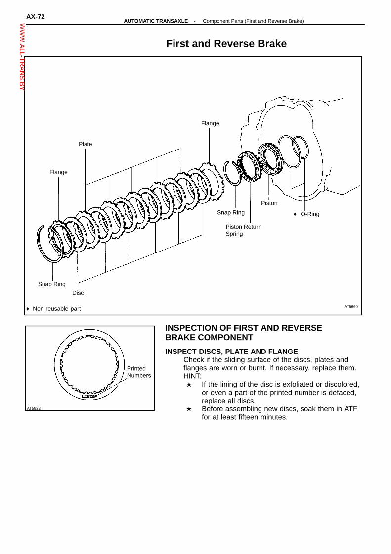
AT5822
♦ Non-reusable part
Disc
Piston ReturnSpring
Snap Ring
Flange
Flange
First and Reverse Brake
Plate
Piston
♦ O-Ring
Snap Ring
AT5660
INSPECTION OF FIRST AND REVERSEBRAKE COMPONENT
INSPECT DISCS, PLATE AND FLANGECheck if the sliding surface of the discs, plates andflanges are worn or burnt. If necessary, replace them.HINT:� If the lining of the disc is exfoliated or discolored,
or even a part of the printed number is defaced,replace all discs.
� Before assembling new discs, soak them in ATFfor at least fifteen minutes.
PrintedNumbers
AX-72-AUTOMATIC TRANSAXLE Component Parts (First and Reverse Brake)W
WW.ALL-TR
ANS.BY

AT0200
SST
AT2920
AT2919
Intermediate Shaft
Rear Bearing
Intermediate Shaft
Oil Seal Ring
Front Bearing
DISASSEMBLY OF INTERMEDIATE SHAFT
1. REMOVE INTERMEDIATE SHAFT FRONT BEARINGUsing SST and press, press out the bearing.SST 09555-55010
2. REMOVE INTERMEDIATE REAR BEARINGUsing SST and press, press out the bearing.SST 09350-32014 (09351-32090) and
09555-55010
SST
-AUTOMATIC TRANSAXLE Component Parts (Intermediate Shaft)AX-73W
WW.ALL-TR
ANS.BY
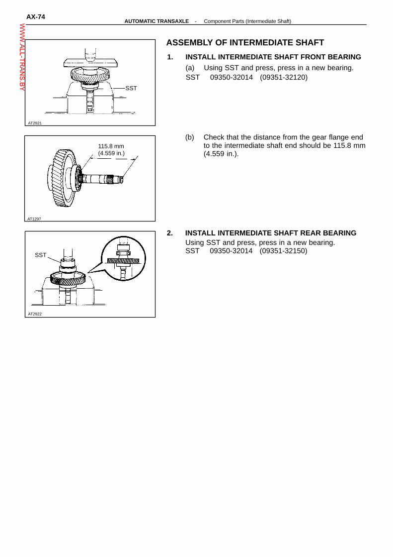
AT1297
AT2922
AT2921
ASSEMBLY OF INTERMEDIATE SHAFT
1. INSTALL INTERMEDIATE SHAFT FRONT BEARING(a) Using SST and press, press in a new bearing.SST 09350-32014 (09351-32120)
SST
(b) Check that the distance from the gear flange endto the intermediate shaft end should be 115.8 mm(4.559 in.).
115.8 mm(4.559 in.)
2. INSTALL INTERMEDIATE SHAFT REAR BEARINGUsing SST and press, press in a new bearing.SST 09350-32014 (09351-32150)
SST
AX-74-AUTOMATIC TRANSAXLE Component Parts (Intermediate Shaft)W
WW.ALL-TR
ANS.BY

AT2924
N-m (kgf-cm, ft-lbf)
AT2925
Non-reusable part
: Specified torque
Snap Ring
Planetary Sun Gear
Bearing
Bearing
Outer Race
♦ Spacer
♦ Lock Nut
Drive Pinion withOutput Flange
Ring Gear
Counter Shaft
Counter Shaft
Snap Ring
See page AX-81 Outer Race
Inner Race
Snap Ring
Bearing
Race
UnderdrivePlanetary Gear
AT2923
DISASSEMBLY OF COUNTER SHAFT
1. REMOVE UNDERDRIVE PLANETARY SUN GEARFROM COUNTER SHAFT
2. MEASURE STARTING TORQUE OF COUNTERSHAFT(a) Using SST, temporarily tighten the lock nut.SST 09350-32014 (09351-32170)
SST
-AUTOMATIC TRANSAXLE Component Parts (Counter Shaft)AX-75W
WW.ALL-TR
ANS.BY
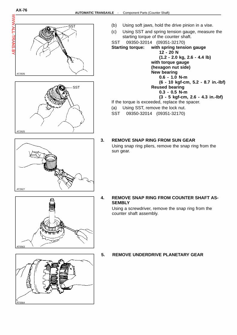
AT2926
AT2925
AT0564
AT0563
(b) Using soft jaws, hold the drive pinion in a vise.
(c) Using SST and spring tension gauge, measure thestarting torque of the counter shaft.
SST 09350-32014 (09351-32170)Starting torque: with spring tension gauge
12 - 20 N(1.2 - 2.0 kg, 2.6 - 4.4 lb)
with torque gauge(hexagon nut side)New bearing
0.6 - 1.0 N-m(6 - 10 kgf-cm, 5.2 - 8.7 in.-lbf)
Reused bearing0.3 - 0.5 N-m(3 - 5 kgf-cm, 2.6 - 4.3 in.-lbf)
If the torque is exceeded, replace the spacer.(a) Using SST, remove the lock nut.SST 09350-32014 (09351-32170)
SST
SST
3. REMOVE SNAP RING FROM SUN GEARUsing snap ring pliers, remove the snap ring from thesun gear.
AT2927
4. REMOVE SNAP RING FROM COUNTER SHAFT AS-SEMBLYUsing a screwdriver, remove the snap ring from thecounter shaft assembly.
5. REMOVE UNDERDRIVE PLANETARY GEAR
AX-76-AUTOMATIC TRANSAXLE Component Parts (Counter Shaft)W
WW.ALL-TR
ANS.BY

AT2928
AT2929
AT2930
AT2931
AT0565
6. REMOVE THRUST NEEDLE ROLLER BEARING ANDRACE
7. REMOVE DRIVE PINION WITH OUTPUT FLANGE,BEARING, INNER RACE AND SPACER(a) Using SST and press, remove the drive pinion
with output flange, bearing and inner race.SST 09350-32014 (09351-32150, 09351-32130),
09555-55010
SST
(b) Remove the spacer from the counter shaft.
8. REMOVE RING GEAR(a) Using a screwdriver, remove the snap ring from
the counter shaft.
(b) Remove the ring gear from the counter shaft.
-AUTOMATIC TRANSAXLE Component Parts (Counter Shaft)AX-77W
WW.ALL-TR
ANS.BY

AT0568
AT2932
AT7998
AT4585
SST
9. REMOVE BEARINGUsing SST and press, remove the bearing.SST 09950-00020
SST
10. REMOVE BEARING OUTER RACESUsing a brass bar and hammer, tap out both bearingouter races.
INSPECTION OF COUNTER SHAFTCOMPONENTS
1. MEASURE PLANETARY SUN GEAR BUSHING INSIDEDIAMETERUsing a caliper gauge, measure the bushing inside di-ameter of the planetary sun gear as shown.Standard inside diameter: 29.800 - 29.825 mm
(1.17322 - 1.17421 in.)Maximum inside diameter: 29.870 mm (1.17598 in.)
2. MEASURE PLANETARY PINION GEAR THRUSTCLEARANCEUsing a feeler gauge, measure the planetary piniongear thrust clearance.Standard clearance: 0.2 - 0.5 mm
(0.008 - 0.020 in.)Maximum clearance: 0.5 mm (0.020 in.)If the clearance is greater than the maximum, replacethe planetary gear assembly.
ASSEMBLY OF COUNTER SHAFT
1. INSTALL BEARING TO COUNTER SHAFTUsing SST and press, press in the bearing of the thickinner race side.SST 09350-32014 (09351-32180)
2. INSTALL RING GEAR(a) Install the ring gear to the counter shaft.
AT2933
AX-78-AUTOMATIC TRANSAXLE Component Parts (Counter Shaft)W
WW.ALL-TR
ANS.BY

AT2934
AT7921
SST
AT2929
AT0582
AT0581
(b) Install the snap ring.
3. INSTALL BEARING OUTER RACES TO DRIVE PIN-ION(a) Using SST and press, press in the thick race to
the flange side of the drive pinion.SST 09350-32014 (09351-32090, 09351-32180)SST
(b) Using SST and press, press in the thin race to theother side.
SST 09350-32014 (09351-32154, 09351-32180)
SST
4. INSTALL DRIVE PINION TO COUNTER SHAFT(a) Install the new spacer to the counter shaft.
(b) Install the drive pinion to the counter shaft.
-AUTOMATIC TRANSAXLE Component Parts (Counter Shaft)AX-79W
WW.ALL-TR
ANS.BY

AT2936
AT7922
AT0588
AT2937
AT2935
5. INSTALL ANOTHER BEARING TO COUNTER SHAFTUsing SST and press, press in the another bearing.SST 09350-32014 (09351-32180)NOTICE: Be sure there is some clearance betweenthe output flange and bearing.
SST
6. INSTALL BEARING INNER RACEUsing SST and press, press in the inner race.SST 09350-32014 (09351-32180)NOTICE: Be sure there is some clearance.
SST
7. ADJUST COUNTER SHAFT STARTING TORQUE(a) Using SST and press, press in the counter driven
gear to the counter shaft.SST 09354-32014 (09351-32100)
SST
(b) Install SST to the driven gear.SST 09350-32014 (09351-32032)
SST
(c) Secure the counter shaft by holding the SST in avise.
SST 09350-32014 (09351-32032)
SST
AX-80-AUTOMATIC TRANSAXLE Component Parts (Counter Shaft)W
WW.ALL-TR
ANS.BY

AT0590
SST
AT2938
AT0588
AT2939
SST
AT0589
Fulcrum Length
SST
(d) Temporarily install the new lock nut, and using SST,tighten the lock nut until the counter shaft startingtorque is in specification.
SST 09350-32014 (09361-32170)Torque (Reference): 117 - 216 N-m(A241E, A243L) (1,800 - 2,200 kgf-cm,
130 - 159 ft-lbf)Torque (Reference): 157 - 193 N-m(A240L, A241H) (1,610 - 1,970 kgf-cm,
116 - 142 ft-lbf)HINT: Use a torque wrench with a fulcrum length of 42 cm(16.54 in.).(e) Using soft jaws, , hold the drive pinion in a vise.
(f) Using SST and spring tension gauge, measure thestarting torque of the counter shaft.
SST 09350-32014 (09351-32170)Starting torque: with tension gauge
12 - 20 N(1.2 - 2.0 kg, 2.6 - 4.4 lb)
with torque gauge(hexagon nut side)New bearing
0.6 - 1.0 N-m(6 - 10 kgf-cm, 5.2 - 8.7 in.-bf)
Reused bearing0.3 - 0.5 Nrrn(3 - 5 kgf-cm, 2.6 - 4.3 in.-lbf)
If the starting torque is exceeded, replace the spacer andretorque.HINT: Before measuring the starting torque, sung downthe bearing by turning the counter shaft.(g) Using a punch and hammer, stake the lock nut.
(h) Remove the SST from the counter driven gear.SST 09350-32014 (09351-32032)
SST
(i) Using SST, remove the counter driven gear.SST 09350-32014 (09351-32061)
-AUTOMATIC TRANSAXLE Component Parts (Counter Shaft)AX-81W
WW.ALL-TR
ANS.BY

Outer Diameter Inner Diameter
A241EA243L
RaceBearing
41.8 (1.646)43.85 (1.726)
30.0 (1.181)31.0 (1.220)
A240LA241H
RaceBearing
41.8 (1.646)43.7 (1.720)
30.0 (1.181)31.0 (1.220)
AT0585
AT2940
AT2927
AT2924
AT0565
Bearing and race:
mm (in.)
8. INSTALL RACE AND BEARINGCoat the race and bearing with petroleum jelly andinstall them to the counter shaft.
9. INSTALL UNDERDRIVE PLANETARY GEAR(a) Install the underdrive planetary gear to the count-
er shaft.
(b) Install the snap ring.
10. INSTALL UNDERDRIVE PLANETARY SUN GEAR(a) Using snap ring pliers, install the snap ring to the
sun gear.
(b) Install the underdrive planetary sun gear to thecounter shaft as shown.
AX-82-AUTOMATIC TRANSAXLE Component Parts (Counter Shaft)W
WW.ALL-TR
ANS.BY

AT2942
Thrust Washer
AT0572
♦ Non-reusable part
Underdrive Clutch Drum
Anti-RattleClip
Snap Ring
Spring Plate
Flange
A241E
Oil Seal Ring
Disc
Snap Ring One-W ay Clutch
A240LA241HA243L
Underdrive Clutch and One-WayClutch No. 3
Plate
Piston
ThrustWasher
Return Spring
AT5838
DISASSEMBLY OF UNDERDRIVE CLUTCH
1. REMOVE ONE-WAY CLUTCH FROM CLUTCHDRUMRemove the one-way clutch and thrust washer fromthe underdrive clutch drum.
2. REMOVE SNAP RINGUsing a screwdriver, remove the snap ring.
♦ O-Ring
-AUTOMATIC TRANSAXLE Component Parts (Underdrive Clutchand One-Way Clutch No. 3)
AX-83WWW.ALL-TR
ANS.BY

AT2944
SST
AT2945
AT5695
AT2947
AT3112
3. REMOVE FLANGE, DISCS AND PLATESRemove the flange, discs and plates from the clutchdrum.
4. REMOVE RETURN SPRING AND SPRING PLATE(a) Using SST and press, compress the return spring
retainer.SST 09350-32014 (09351-32070)(b) Using snap ring pliers, remove the snap ring.
(c) Remove SST.
(d) Remove the return spring and spring plate.
5. REMOVE UNDERDRIVE CLUTCH PISTON(a) Install the underdrive clutch to the transaxle case.HINT: Before installing the clutch, install the oil sealrings to the transaxle case.(b) Apply compressed air into the oil passage of the
case, and remove the piston from the clutchdrum.
(c) If the piston does not pop out with compressedair, use needle-nose pliers to remove it.
6. REMOVE O-RINGS FROM PISTONUsing a screwdriver, remove the two O-rings from theunderdrive clutch piston.
AX-84 -AUTOMATIC TRANSAXLE Component Parts (Underdrive Clutchand One-Way Clutch No. 3)W
WW.ALL-TR
ANS.BY

AT5837
AT0576 AT0577
AT2948
Front Side
AT5834
INSPECTION OF UNDERDRIVE CLUTCHCOMPONENTS
1. INSPECT DISCS, PLATES AND FLANGESCheck if the sliding surface of the discs, plates andflanges are worn or burnt. If necessary, replace them.HINT:� If the lining of the disc is exfoliated or discolored,
or even a part of the printed numbers are defaced,replace the disc.
� Before assembling new discs, soak them in ATFfor at least fifteen minutes.
PrintedNumber
2. INSPECT UNDERDRIVE CLUTCH PISTON(a) Check that the check ball is free by shaking the
piston.
(b) Check that the valve does not leak by applyinglow-pressure compressed air.
3. INSPECT UNDERDRIVE CLUTCH DRUMUsing a caliper gauge, measure the bushing inside di-ameter of the underdrive clutch drum as shown.Standard inside diameter:
Front side 46.500 - 46.525 mm(1.53071 - 1,83169 in.)
Rear side 55.000 - 55.030 mm(2.16535 - 2.16653 in.)
Maximum inside diameter:Front side 46.570 mm (1.83346 in.)Rear side 55.080 mm (2.16850 in.)
Rear Side
-AUTOMATIC TRANSAXLE Component Parts (Underdrive Clutchand One-Way Clutch No. 3)
AX-85WWW.ALL-TR
ANS.BY

AT8000
Stopper
AT2949
AT2950
AT2945
Spring Seat
AT2944
SST
ASSEMBLY OF UNDERDRIVE CLUTCH
1. INSTALL UNDERDRIVE CLUTCH PISTON INTOCLUTCH DRUM(a) Install the two new O-rings to the piston.HINT: Before installing, coat the O-rings with ATF.
(b) Install the underdrive clutch piston into the clutchdrum.
HINT: Be careful not to damage the O-rings.
2. INSTALL SPRING SEAT AND RETURN SPRING(a) Install the spring seat and return spring to the un-
derdrive clutch as shown.Return Spring
(b) Using SST and press, compress the return springretainer.
SST 09350-32014 (09351-32070)(c) Using snap ring pliers, install the snap ring.
HINT: Install the snap ring as shown.(d) Remove SST.SST 09350-32014 (09351-32070)
Stopper
AX-86 -AUTOMATIC TRANSAXLE Component Parts (Underdrive Clutchand One-Way Clutch No. 3)W
WW.ALL-TR
ANS.BY

AT2952
AT2942
AT8001
Hold
Free
AT3113
Plate
Flange
Plate
3. INSTALL PLATES, DISCS AND FLANGEInstall in order: D = Disc P = Plate F = Flange
A241E F-D-P-P-D-P-P-D-PA243L F-D-P-D-P-D-PA240LA241H
HINT: Install the flange the flat end facing downward.
Flange
Disc
Disc
4. INSTALL SNAP RINGInstall the snap ring to the underdrive clutch.
5. INSTALL ONE-WAY CLUTCH TO CLUTCH DRUM(a) Install the thrust washer to clutch drum.
(b) Install the one-way clutch with the claw of retain-er up.
Thrust Washer
Lock
Turn
6. CHECK OPERATION OF ONE-WAY CLUTCHHold the one-way clutch drum and turn the one-wayclutch.Check that the one-way clutch turns freely counter-clockwise and lock clockwise.
-AUTOMATIC TRANSAXLE Component Parts (Underdrive Clutchand One-Way Clutch No. 3)
AX-87WWW.ALL-TR
ANS.BY

AT5823
♦ Non-reusable part�Precoated part
N-m (kgf-cm, ft-lbf)
10 (100, 7)
Oil Gallery Cover
Spring
♦ Gasket
7.4 (75, 65 in.-lbf)
Flange
Disc
Underdrive Brake Piston
♦ O-Ring
Underdrive Brake and B 4Accumulator Piston
Return Spring
Snap Ring
Plate
Oil Seal Ring
B4 Accumulator Piston
♦ O-Ring
Bolt
: Specified torque
AT2953
INSPECTION OF UNDERDRIVE BRAKECOMPONENTS
INSPECT DISCS, PLATES AND FLANGESCheck that the sliding surface of disc, plate and flangeworn or burnt. If necessary, replace them.HINT:� If the lining of the disc is exfoliated or discolored,
or even a part of the printed numbers are de-faced, replace the disc.
� Before assembling new discs, soak them in ATFfor at least fifteen minutes.
PrintedNumbers
AX-88 -AUTOMATIC TRANSAXLE Component Parts (Underdrive Brake and B4Accumulator Piston)W
WW.ALL-TR
ANS.BY

AdjustingRing
Plunger Sleeve
♦ Non-reusable partAT8455 AT3140
Specified torqueNo. 2 Solenoid
6.5 (65, 56 in.-lbf)
No. 3 Solenoid
♦ O-Ring
Plate
♦ Gasket
Lower Valve Body
Plate
Upper Valve Body
6.5 (65, 56 in.-lbf)
A241E
Lower ValveBody Cover
Stainer
No. 1 Solenoid
♦ Gasket
Valve BodyCOMPONENTS
A240L, A241L, A243L
6.5 (65, 56 in.-lbf)
♦ No. 1 Gasket
♦ No. 2 Gasket
♦ Gasket
Plate
♦ O-Ring
♦ O-Ring
Solenoid
Lower Valve Body Cover6.5 (65, 56 in.-lbf)
N-m (kgf-cm, ft-lbf)
10 (100, 7)
(Disassembly of Valve Body)1. NOTE THE NUMBERS OF ADJUSTING RINGS
HINT: Count the number of adjusting rings before dis-assembly of the valve body because the throttle pres-sure is changed according to the number. (Some of thevalve bodies do not have any adjusting rings.)
2. NOTE THE POSITION OF PLUNGER SLEEVENote which step at the end of the plunger sleeve is incontact with the valve body.HINT: Be certain to check this before disassembly be-cause the line pressure changes according to the partof the plunger sleeve which comes into contact with thevalve body.
AT3045
-AUTOMATIC TRANSAXLE (A240L, A241E, A243L) Component Parts (Valve Body) AX-89WWW.ALL-TR
ANS.BY
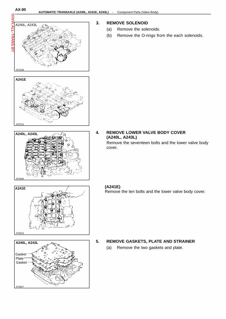
AT3138
AT5724
AT3046
A240L, A243L
AT3047
Gasket
A240L, A243L
Gasket
AT8033
3. REMOVE SOLENOID(a) Remove the solenoids.
(b) Remove the O-rings from the each solenoids.
A240L, A243L
A241E
4. REMOVE LOWER VALVE BODY COVER(A240L, A243L)Remove the seventeen bolts and the lower valve bodycover.
(A241E)Remove the ten bolts and the lower valve body cover.
A241E
5. REMOVE GASKETS, PLATE AND STRAINER(a) Remove the two gaskets and plate.
Plate
AX-90-AUTOMATIC TRANSAXLE (A240L, A241E, A243L) Component Parts (Valve Body)W
WW.ALL-TR
ANS.BY

AT8032
Gasket
Gasket
AT3048
A240L, A243L
AT3058
AT3055
A241E
A241E
Plate
(b) Remove the strainer. (A240L, A243L only)Strainer
6. REMOVE BOLTS FROM UPPER VALVE BODYRemove the eight bolts from the upper valve body.
7. REMOVE BOLTS FROM LOWER VALVE BODYRemove the five bolts from the lower valve body.(A240L, A243L)
A240L, A243L
Remove the nine bolts from the lower valve body.(A241E)
AT2588
-AUTOMATIC TRANSAXLE (A240L, A241E, A243L) Component Parts (Valve Body) AX-91WWW.ALL-TR
ANS.BY

8. LIFT OFF LOWER VALVE BODY AND PLATE ASSINGLE UNITHold the plate to the lower valve body and lift off thelower valve body.HINT: Be careful that the valves, springs and strainerdo not fall out.
9. REMOVE PLATE AND GASKETS FROM LOWERVALVE BODY
AT7982
AX-92-AUTOMATIC TRANSAXLE (A240L, A241E, A243L) Component Parts (Valve Body)W
WW.ALL-TR
ANS.BY

N-m (kgf-cm, ft-lbf)AT5712
Plug
Throttle Valve Sleeve
Down Shift Plug
Pin
Lock-Up RelayControl Valve
10 (100, 7)
Primary Regulator Plunger
Strainer*1
Cam
Check Ball
Accumulator Control Valve
Plug
KeyPin
The throttle pressure is changedaccording to the number of adjust-ing rings.When assembling the valve body,install the same number of adjust-ing rings as were removed.
A241E: Low CoastModulator ValveA240L, A243L: 2nd CoastModulator Valve
Primary RegulatorValve
Strainer*1
Lock-Up RelayValve
Throttle Valve
Check Ball
Key
(Upper Valve Body)
COMPONENTS
Adjusting Ring
Cut-Back ValveKey
Plug
Plug
Vibrating Stopper
Pin
Washer
Primary Regulator Plunger Sleeve
WasherPin
Lock-Up RelayValve Sleeve
Plug
Throttle ModulatorValve
Pin
Pin
: Specified torque*1A241E Only*2 A241E and A240L Only
-AUTOMATIC TRANSAXLE (A240L, A241E, A243L) Component Parts (Valve Body)AX-93W
WW.ALL-TR
ANS.BY

AT8488
Spring Free Lengthmm (in.)
Coil OuterDiameter mm(in.)
Number ofCoils Color
Primary Regulator Valve Spring 66.7 (2.626) 18.6 (0.732) 12.5 Purple
Lock-up Relay Valve Spring 18.8 (0.740) 5.1 (0.201) 14.5 None
Low Coast Modulator Valve Spring A241E 27.5 (1.083) 8.3 (0.327) 12.5 Yellow
2nd Coast Modulator Valve SpringA243L 29.7 (1.169) 8.3 (0.327) 12.5 Red
A240L 29.6 (1.165) 8.3 (0.327) 12.5 Red
Down Shift Plug Spring 29.8 (1.173) 8.7 (0.343) 13.5
A241EA243L
Throttle Valve Spring 29.2 (1.150) 9.2 (0.362) 9.5 Light Green
Throttle Modulator Valve Spring 29.9 (1.177) 9.0 (0.354) 15.5 Green
Accumulator Control Valve SpringA243L 38.2 (1.504) 10.0 (0.394) 11.5 Yellow
A241E 33.2 (1.307) 10.0 (0.394) 11.5 Orange
SPECIFICATIONS OF VALVE BODY SPRING
White(A240L)Red
HINT: During reassembly please refer to the spring specifications above to help discriminate be-tween the different springs.
SECTIONAL VIEW OF VALVE BODY
AX-94-AUTOMATIC TRANSAXLE (A240L, A241E, A243L) Component Parts (Valve Body)W
WW.ALL-TR
ANS.BY

AT5689
3.2(0.126)Low or 2nd Coast Modulator Valve
3.210.1261Cut-back Valve
5.0(0.197)Accumulator Control Valve
WidthHeight
mm (in.)
Pin
Vibrating Stopper
Key
AT5679
A240LA243L
Key Thickness
15.0(0.591)
3.2(0.126)
16.0(0.630)
5.0(0.197)
21.2(0.835)
5.0(0.197)
LOCATION OF KEYS, PINS, VIBRATING STOPPER AND CHECK BALLS
1. KEY STOPPER AND PIN
Pin
Key
Pin
PinKey
2. CHECK BALL
A241E
AT5678
-AUTOMATIC TRANSAXLE (A240L, A241E, A243L) Component Parts (Valve Body)AX-95W
WW.ALL-TR
ANS.BY

Key
3 - 4 Shift Valve
Plug
Plug
Secondary Regulator Valve
Key
Plug
Strainer
Cooler By-Pass Valve
Pressure Relief Valve
Plug
(Lower Valve Body, A241E)COMPONENTS
A241E
2 - 3 Shift Valve
Key
Key
2nd Coast Modulator Valve
Lock-Up Signal Valve
Key
1 - 2 Shift Valve
Key
Plug
AT8374
AX-96-AUTOMATIC TRANSAXLE (A240L, A241E, A243L) Component Parts (Valve Body)W
WW.ALL-TR
ANS.BY

SpringFree Lengthmm (in.)
Coil OuterDiametermm (in.)
Numberof Coils Color
Cooler By-pass Valve Spring 18.3 (0.720) 12.0 (0.472) 6.5 Yellow
Pressure Relief Valve Spring 11.2 (0.441) 6.4 (0.252) 7.5 None
2 - 3 Shift Valve Spring 30.8 (1.213) 9.7 (0.382) 10.5 Purple
2nd Coast Modulator Valve Spring 29.6 (1.165) 8.3 (0.327) 12.5 Red
Lock-up Signal Valve Spring 30.0 (1.181) 8.2 (0.323) 11.5 Orange
Secondary Regulator Valve Spring 27.4 (1.079) 11.0 (0.433) 11.5 Blue
1 - 2 Shift Valve Spring 30.8 (1.213) 9.7 (0.382) 10.5 Purple
3 - 4 Shift Valve Spring 30.8 (1.213) 9.7 (0.382) 10.5 Purple
SPECIFICATIONS OF VALVE BODY SPRING
HINT: During reassembly please refer to the spring specifications above to help discriminate be-tween the different springs:
SECTIONAL VIEW OF VALVE BODY
Q04983
-AUTOMATIC TRANSAXLE (A240L, A241E, A243L) Component Parts (Valve Body)AX-97W
WW.ALL-TR
ANS.BY

AT5726 AT5727
3.2(0.126)Secondary Regulator Valve
3.2(0.126)3 - 4 Shift Valve
5.0(0.197)1 - 2 Shift Valve
3.2(0.126)Lock-up Signal Valve
5.0(0.197)2nd Coast Modulator Valve
5.0(0.197)2 - 3 Switch Valve
Height Thickness
Key
Key
Strainer
Key
(Upper Side)
Key Width
11.5(0.453)
3.2(0.126)
11.5(0.453)
3.2(0.126)
11.5(0.453)
5.0(0.197)
11.5(0.453)
3.2(0.126)
11.5(0.453)
5.0(0.197)
9.2(0.362)
5.0(0.197)
LOCATION OF KEYS AND STRAINER
A241E
(Lower Side)
Key
Key
Key
mm (in.)
AX-98-AUTOMATIC TRANSAXLE (A240L, A241E, A243L) Component Parts (Valve Body)W
WW.ALL-TR
ANS.BY

Key
Plug
Key
Plug
3 - 4 Switch Valve
Detent Regulator ValvePlug
2 - 3 Shift Valve
Plug
3 - 4 Shift Valve
Plug
Plug
Key
Plug
Low CoastShift Valve
Plug
Stainer
Pressure Relief Valve
Key
Key
Key
(Lower Valve Body, A240L, A243L)COMPONENTS
A240L, A243L
Cooler By-Pass Valve
Secondary Regulator Valve
Key
Plug3 - 4 Coast Shift Valve
3rd Coast Shift ValveLow ModulatorValve Intermediate
Shift Valve
Lock-Up SignalValve
Key
Key
Key
Plug
Key
1 - 2 Shift Upper Valve
1 - 2 Shift Lower Valve
Plug
AT3051AT3052
-AUTOMATIC TRANSAXLE (A240L, A241E, A243L) Component Parts (Valve Body)AX-99W
WW.ALL-TR
ANS.BY

A240L, A243L
SpringFree Lengthmm (in.)
Coil OuterDiametermm (in.)
Number ofCoils Color
Secondary Regulator Valve Spring 27.4 (1.079) 11.0 (0.433) 11.5 Blue
1 - 2 Shift Valve Spring 27.2 (1.071) 6.4 (0.252) 15.5 Yellow
Low Modulator Valve Spring 29.2 (1.150) 8.3 (0.327) 12.5 None
2 - 3 Shift Valve Spring 27.7 (1.091) 8.3 (0.327) 11.0 None
Cooler By-pass Valve Spring 18.3 (0.720) 12.0 (0.472) 6.5 Yellow
Pressure Relief Valve Spring 11.2 (0.441) 6.4 (0.252) 7.5 None
3 - 4 Shift Valve Spring A240L, A243L 27.7 (1.091) 8.3 (0.327) 11.0 None
Lock-up Signal Valve SpringA240L 35.7 (1.406) 8.1 (0.319) 14.5 Yellow
A243L 18.2 (0.717) 8.1 (0.319) 8.0 Blue
Detent Regulator Valve Spring 32.0 (1.260) 8.3 (0.327) 15.5 Brown
3 - 4 Switch Valve Spring 30.9 (1.217) 7.0 (0.276) 18.5 None
SPECIFICATIONS OF VALVE BODY SPRINGS
HINT: During reassembly please refer to the spring specifications above to help discriminate be-tween the different springs.
SECTION VIEW OF VALVE BODY
Q00984
AX-100-AUTOMATIC TRANSAXLE (A240L, A241E, A243L) Component Parts (Valve Body)W
WW.ALL-TR
ANS.BY
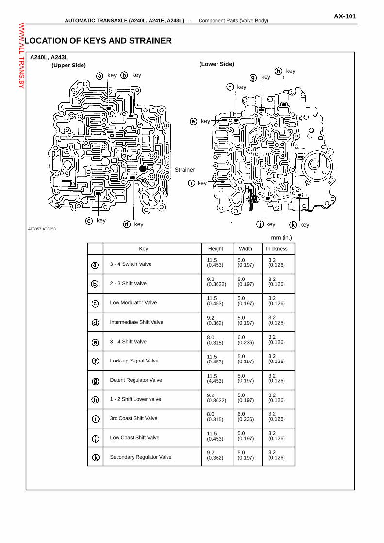
9.2(0.362)
5.0(0.197)
11.5(0.453)
3.2(0.126)
8.0(0.315)
6.0(0.236)
5.0(0.197)
9.2(0.3622)
11.5(4.453)
5.0(0.197)
11.5(0.453)
5.0(0.197)
6.0(0.236)
3.2(0.126)
5.0(0.197)
3.2(0.126)
11.5(0.453)
5.0(0.197)
9.2(0.3622)
5.0(0.197)
5.0(0.197)
3.2(0.126)
Key Width
mm (in.)
keykey
key
key
key
A240L, A243L(Upper Side)
key
Height Thickness
3 - 4 Switch Valve11.5(0.453)
2 - 3 Shift Valve3.2(0.126)
Low Modulator Valve3.2(0.126)
Intermediate Shift Valve9.2(0.362)
3 - 4 Shift Valve8.0(0.315)
Lock-up Signal Valve3.2(0.126)
Detent Regulator Valve3.2(0.126)
1 - 2 Shift Lower valve3.2(0.126)
3rd Coast Shift Valve3.2(0.126)
Low Coast Shift Valve5.0(0.197)
Secondary Regulator Valve3.2(0.126)
key
LOCATION OF KEYS AND STRAINER
(Lower Side)key
key
Strainer
keykey
AT3057 AT3053
-AUTOMATIC TRANSAXLE (A240L, A241E, A243L) Component Parts (Valve Body)AX-101W
WW.ALL-TR
ANS.BY

Pub. Name Pub. No
’92 Corolla Repair Manual’92 Celica Repair Manual’92 MR2 Repair Manual
RM250URM251U1RM252U1
Automatic Transaxle Applicable Model
A240LA241EA241HA243L
’92 Corolla’92 MR2, ’92 CeIica’92 Corolla’92 Celica
FOREWORD
This repair manual covers Disassembly, Inspection and As-sembly procedures for the following Automatic Transaxles:
For On-vehicle Servicing (Inspection, Adjustment, Trouble-shooting, Removal and Installation) of Automatic Transaxle,refer to the repair manual for the applicable vehicle models.
All information contained in this manual is the most up-to-dateat the time of publication. However, specifications and proce-dures are subject to change without notice.
TOYOTA MOTOR CORPORATION
WWW.ALL-TR
ANS.BY
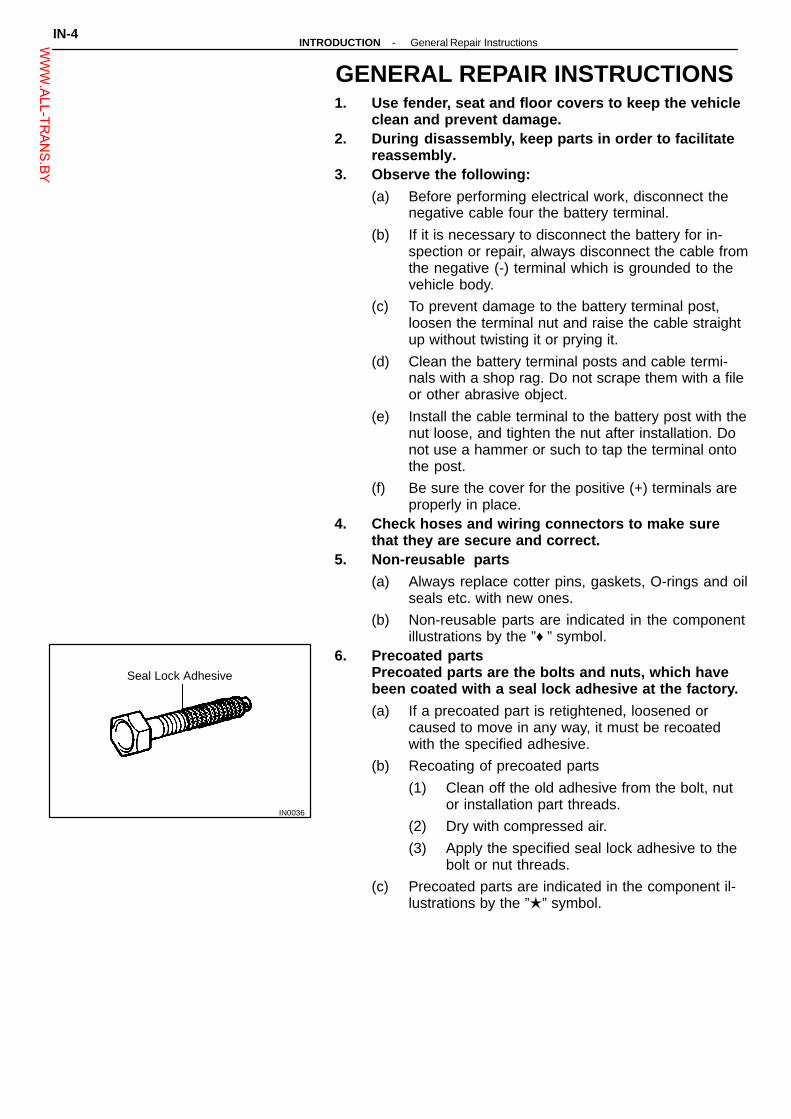
IN0036
Seal Lock Adhesive
GENERAL REPAIR INSTRUCTIONS1. Use fender, seat and floor covers to keep the vehicle
clean and prevent damage.2. During disassembly, keep parts in order to facilitate
reassembly.3. Observe the following:
(a) Before performing electrical work, disconnect thenegative cable four the battery terminal.
(b) If it is necessary to disconnect the battery for in-spection or repair, always disconnect the cable fromthe negative (-) terminal which is grounded to thevehicle body.
(c) To prevent damage to the battery terminal post,loosen the terminal nut and raise the cable straightup without twisting it or prying it.
(d) Clean the battery terminal posts and cable termi-nals with a shop rag. Do not scrape them with a fileor other abrasive object.
(e) Install the cable terminal to the battery post with thenut loose, and tighten the nut after installation. Donot use a hammer or such to tap the terminal ontothe post.
(f) Be sure the cover for the positive (+) terminals areproperly in place.
4. Check hoses and wiring connectors to make surethat they are secure and correct.
5. Non-reusable parts
(a) Always replace cotter pins, gaskets, O-rings and oilseals etc. with new ones.
(b) Non-reusable parts are indicated in the componentillustrations by the ”♦ ” symbol.
6. Precoated partsPrecoated parts are the bolts and nuts, which havebeen coated with a seal lock adhesive at the factory.
(a) If a precoated part is retightened, loosened orcaused to move in any way, it must be recoatedwith the specified adhesive.
(b) Recoating of precoated parts
(1) Clean off the old adhesive from the bolt, nutor installation part threads.
(2) Dry with compressed air.
(3) Apply the specified seal lock adhesive to thebolt or nut threads.
(c) Precoated parts are indicated in the component il-lustrations by the ”�” symbol.
IN-4-INTRODUCTION General Repair InstructionsW
WW.ALL-TR
ANS.BY

7. When necessary, use a sealer on gaskets to preventleaks.
8. Carefully observe all specifications for bolt tighten-ing torques. Always use a torque wrench.
9. Use of special service tools (SST) and special ser-vice materials (SSM) may be required, depending onthe nature of the repair. Be sure to use SST and SSMwhere specified and follow the proper work proce-dure. A list of SST and SSM can be found at the prep-aration of AX section.
10. When replacing fuses, be sure the new fuse has thecorrect amperage rating. DO NOT exceed the fuseamp rating or use one of a lower rating.
11. Care must be taken when jacking up and supportingthe vehicle. Be sure to lift and support the vehicle atthe proper locations.(a) If the vehicle is to be jacked up only at the front or
rear end, be sure to block the wheels in order toensure safety.
(b) After the vehicle is jacked up, be sure to support iton stands. It is extremely dangerous to do anywork on the vehicle raised on jack alone, even for asmall job that can be finished quickly.
-INTRODUCTION General Repair InstructionsIN-5W
WW.ALL-TR
ANS.BY

N-m (kgf-cm, ft-lbf)
AT6238♦ Non-reusable part: Specified torque
♦ Oil Seal
Driven Gear
Stator Shaft
Oil Seal Ring
Oil Pump Body
Drive Gear
7.4 (75, 65 in.-Ibf)
HOW TO USE THIS MANUALTo assist you in finding your way through the manual, theSection Title and major heading are given at the top of everypage.
REPAIR PROCEDURES
Most repair operations begin with an overview illustration. Itidentifies the components and shows how the parts fit together.
Example:
IN-2-INTRODUCTION How to Use This ManualW
WW.ALL-TR
ANS.BY

Illustration:what to do and where
This format provides the experienced technician with a FASTTRACK to the information needed. The upper case task head-ing can be read at a glance and only when necessary, the textbelow it provides detailed information. Important specificationsand warnings always stand out in bold type.
SST 09350-32014 (09351-32190)
If replacing the disc, plate or flange, check the pistonstroke:
Set part No.
Piston stroke: 1.41 - 1.82 mm (0.0555 - 0.0717 in.)
The procedures are presented in a step-by-step format:� Illustration shows what to do and where to do it.� The task heading tells what to do.� The detailed text tells how to perform the task and
gives other information such as specifications andwarnings.
Example:Task heading: what to do
7. CHECK PISTON STROKE OF FORWARD CLUTCH
Detail text: how to do it
Using a dial indicator (long type pick or SST), measurethe forward clutch piston stroke applying and releasingthe compressed air (392 - 785 kPa, 4 - 8 kgf/cm2 or57 - 114 psi) as shown.
Component part No.
Specification
REFERENCES
References have been kept to a minimum. However, whenthey are required you are given the page to go to.
SPECIFICATIONS
Specifications are presented in bold type throughout the text inthe applicable step. You never have to leave the procedure tolook up your specs. All specifications are also found at theback of AX section, specifications for quick reference.
CAUTIONS, NOTICES, HINTS:� CAUTIONS are presented in bold type, and indicate
there is a possibility of injury to you or other people.� NOTICES are also presented in bold type, and indicate
the possibility of damage to the components being re-paired.
� HINTS are separated from the text but do not appear inbold. They provide additional information to help you effi-ciently perform the repair.
-INTRODUCTION How to Use This ManualIN-3W
WW.ALL-TR
ANS.BY

Transfer driven pinion preload (at starting)
w/ Transfer (Add driven pinion preload)
New bearing
Reused bearing
Drive pinion bearing cage preload (at starting)
New bearing
Reused bearing
Backlash
Transfer ring gear
Oil seal depth
Transfer left case
Transfer right case Left side
Right side
Extension housing
0.0051 - 0.0071 in.
0.12 in.
0 in
0 in.
0.004 - 0.035 in.
2.0 - 3.1 lb
2.7 - 3.1 lb
1.1 - 2.0 lb
4.0 - 6.4 lb
2.0 - 3.1 lb
0.13 - 0.18 mm
3 mm
0 mm
0 mm
0.1 - 0.9 mm
Conical spring washer
Transfer left case side plate washer
0.0394 in.
0.0413 in.
0.0433 in.
0.0453 in.
0.0472 in.
0.0492 in.
0.0512 in.
0.0531 in.
0.0551 in.
0.0571 in.
0.0591 in.
0.0839 in.
0.0850 in.
0.0862 in.
0.0874 in.
0.0886 in.
0.0898 in.
0.0909 in.
0.0921 in.
0.0933 in.
0.0945 in.
0.0957 in.
0.0969 in.
SERVICE SPECIFICATIONSSERVICE DATA
0.9 - 1.4 kg
1.3 - 1.4 kg
0.5 - 0.9 kg
1.8 - 2.9 kg
0.9 - 1.4 kg
8.8 - 13.7 N
12.7 - 13.7 N
4.9 - 8.8 N
17.7 - 28.4 N
8.8 - 13.7 N
Mark
A
B
C
D
E
F
G
H
J
K
L
Mark
71
72
73
74
75
76
77
78
79
80
81
82
1.00 mm
1.05 mm
1.10 mm
1.15 mm
1.20 mm
1.25 mm
1.30 mm
1.35 mm
1.40 mm
1.45 mm
1.50 mm
2.13 mm
2.16 mm
2.19 mm
2.22 mm
2.25 mm
2.28 mm
2.31 mm
2.34 mm
2.37 mm
2.40 mm
2.43 mm
2.46 mm
TR-40-TRANSFER (A241H) Service SpecificationsW
WW.ALL-TR
ANS.BY

Part tightened kgf-cm ft-lbf
Transfer × Transaxle (nut)
Ring gear mounting left case × Right case
Left case × Driven pinion bearing cage
Left case × Control valve sleeve cover
Left case × Case retainer
Left case × Inspection hole cover
Right case × Level gauge guide plate
Extension housing × Driven pinion bearing cage
Mode select lever and rod
Driven pinion lock nut
Left case × Ring gear
Left case × Right case
51
71
29
12
19
12
7
19
9
72
91
25
69
97
39
17
25
17
10
25
13
98
124
33
83
84
85
86
87
88
89
90
91
92
93
94
Mark
A
B
C
D
E
F
G
H
J
K
2.49 mm
2.52 mm
2.55 mm
2.58 mm
2.61 mm
2.64 mm
2.67 mm
2.70 mm
2.73 mm
2.76 mm
2.79 mm
2.82 mm
0.30 mm
0.33 mm
0.36 mm
0.39 mm
0.42 mm
0.45 mm
0.48 mm
0.51 mm
0.54 mm
0.57 mm
SERVICE DATA (Cont’d)
Transfer left case side plate washer (Cont’d)
Transfer ring gear adjusting shim
0.0980 in.
0.0992 in.
0.1004 in.
0.1016 in.
0.1028 in.
0.1039 in.
0.1051 in.
0.1063 in.
0.1075 in.
0.1087 in.
0.1098 in.
0.1110 in.
0.0118 in.
0.0130 in.
0.0142 in.
0.0154 in.
0.0165 in.
0.0177 in.
0.0189 in.
0.0201 in.
0.0213 in.
0.0224 in.
TORQUE SPECIFICATIONS
N-m
700
984
400
170
260
170
100
260
130
1,000
1,260
340
-TRANSFER (A241H) Service SpecificationsTR-41W
WW.ALL-TR
ANS.BY

Second coastbrake
Piston stroke
Piston rod length
1.5 - 3.0 mm
72.9 mm
71.4 mm
Oil pump Body clearance STD
Maximum
Tip clearance STD
Maximum
Side clearance STD
Maximum
Pump body bushing inside diameter Maximum
Stator shaft bushing inside diameter
Front side Maximum
Rear side Maximum
0.07 - 0.15 mm
0.3 mm
0.11 - 0.14 mm
0.3 mm
0.02 - 0.05 mm
0.1 mm
38.18 mm
21.57 mm
27.07 mmDirect clutch Piston stroke A241E
A243L
A240L, A241H
Drum bushing inside diameter
Flange thickness A241E
A243L
A240L, A241H
0.0437 - 0.0579 in.
0.0642 - 0.0776 in.
0.0535 - 0.0673 in.
1.8531 in.
0.102 in.
0.118 in.
0.102 in.
0.110 in.
0.118 in.
0.118 in.
0.1327 in.Forwardclutch
Piston stroke
Flange thickness
1.42 - 1.81 mm
3.00 mm
3.37 mm
Front planetarygear
Sun gear bushing inside diameter Standard
Maximum
Ring gear flange bushing inside diameter
Standard
Planetary pinion gear thrust clearance
Maximum
0.8671 - 0.8680 in.
0.8699 in.
0.7490 - 0.7500 in.
0.020 in.
22.025 - 22.046 mm
22.096 mm
19.025 - 19.050 mm
0.5 mm
Rear planetarygear
Planetary pinion gear thrust clearance
Maximum 0.020 in.
Counter shaft Starting torque with spring tension gauge
with torque gauge
(hexagon nut side) New bearing
Reused bearing
Planetary sun gear bushing inside diameter
Standard
Maximum
Underdrive planetary pinion gear thrust clearance
Maximum
Height (measure the distance between the tip of the
counter shaft and bolt seat of the clutch support.)
End play
29.800 - 29.825 mm
29.870 mm
0.5 mm
33.3 - 35.5 mm
0.23 - 0.89 mm
0.6 - 1.0 N-m 6 - 10 kgf-cm 5.2 - 8.7 in.-lbf
0.3 - 0.5 N-m 3 - 5 kgf-cm 2.6 - 4.3 in.-lbf
1.2 - 2.0 kg
SERVICE SPECIFICATIONSSERVICE DATA
0.059 - 0.118 in.
2.870 in.
2.811 in.
0.0028 - 0.0059 in.
0.012 in.
0.0043 - 0.0055 in.
0.012 in.
0.0008 - 0.0020 in.
0.004 in.
1.5031 in.
0.8492 in.
1.0657 in.1.11 - 1.47 mm
1.63 - 1.97 mm
1.36 - 1.71 mm
47.07 mm
2.6 mm
3.0 mm
2.6 mm
2.8 mm
3.0 mm
3.0 mm
3.37 mm0.0559 - 0.0713 in.
0.1181 in.
0.1327 in.
0.5 mm
2.6 - 4.4 lb
1.1732 - 1.1742 in.
1.1760 in.
0.020 in.
1.311 - 1.398 in.
0.0091 - 0.0350 in.
AX-232-AUTOMATIC TRANSAXLE Service SpecificationsW
WW.ALL-TR
ANS.BY
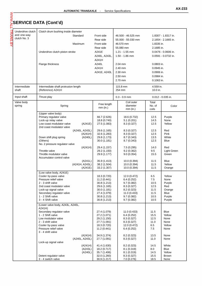
Underdrive clutchand one-wayclutch No. 3
Clutch drum bushing inside diameter
Standard Front side
Rear side
Maximum Front side
Rear side
Underdrive clutch piston stroke A241E
A240L, A243L,
A241H
Flange thickness A240L
A241H
A241E, A243L
1.8307 - 1.8317 in.
2.1654 - 2.1665 in.
1.8335 in.
2.1685 in.
0.0476 - 0.0606 in.
0.0591 - 0.0732 in.
0.0803 in.
0.0945 in.
0.0906 in.
0.0984 in.
0.1063 in.
46.500 - 46.525 mm
55.000 - 55.030 mm
46.570 mm
55.080 mm
1.21 - 1.55 mm
1.50 - 1.86 mm
2.04 mm
2.40 mm
2.30 mm
2.50 mm
2.70 mm
Intermediateshaft
Intermediate shaft protrusion length(Reference) A241H
4.559 in.10.0 in.
Input shaft Thrust play 0.012 - 0.035 in.
Valve bodyspring Spring Free length
mm (in.)
Coil outerdiametermm (in.)
TotalNo. ofcoils
Color
(Upper valve body)Primary regulator valveLock-up relay valveLow coast modulator valve (A241E)2nd coast modulator valve
(A240L, A243L)(A241H)
Down shift plug spring (A240L)(Others)No. 2 pressure regulator valve
(A241H)Throttle valveThrottle modulator valveAccumulator control valve
(A241L)(A241H, A243L)
(A241E)
66.7 (2.626)18.8 (0.740)27.5 (1.083)
29.6 (1.165)32.6 (1.283)29.8 (1.173)30.0 (1.181)
29.4 (1.157)29.2 (1.150)29.9 (1.177)
35.9 (1.413)38.2 (1.504)33.2 (1.307)
18.6 (0.732)5.1 (0.201)8.3 (0.327)
8.3 (0.327)8.3 (0.327)8.7 (0.343)8.7 (0.343)
7.5 (0.295)9.2 (0.362)9.0 (0.354)
10.0 (0.394)10.0 (0.394)10.0 (0.394)
12.514.512.5
12.512.513.512.5
14.09.515.5
11.511.511.5
PurpleNoneYellow
RedPinkWhiteBlue
RedLight GreenGreen
BlueYellowOrange
(Low valve body, A241E)Cooler by-pass valvePressure relief valve2 - 3 shift valve2nd coast modulator valveLock-up signal valveSecondary regulator valve1 - 2 Shift valve3 - 4 Shift valve
18.3 (0.720)11.2 (0.441)30.8 (1.213)29.6 (1.165)30.0 (1.181)27.4 (1.079)30.8 (1.213)30.8 (1.213)
12.0 (0.472)6.4 (0.252)9.7 (0.382)8.3 (0.327)8.2 (0.323)11.0 (0.433)9.7 (0.382)9.7 (0.382)
6.57.510.512.511.511.510.510.5
YellowNonePurpleRedOrangeBluePurplePurple
(Lower valve body, A243L, A240L,A241H)Secondary regulator valve1 - 2 Shift valveLow modulator valve2 - 3 shift valveCooler by-pass valvePressure relief valve3 - 4 shift valve
(A241H)(A240L, A243L)
Lock-up signal valve(A241H)(A243L)(A240L)
Detent regulator valve3 - 4 switch valve
27.4 (1.079)27.2 (1.071)29.2 (1.150)27.7 (1.091)18.3 (0.720)11.2 (0.441)
34.9 (1.374)27.7 (1.091)
41.4 (1.630)18.2 (0.717)35.7 (1.406)32.0 (1.260)30.9 (1.217)
11.0 (0.433)6.4 (0.252)8.3 (0.327)8.3 (0.327)12.0 (0.472)6.4 (0.252)
8.2 (0.323)8.3 (0.327)
8.2 (0.323)8.1 (0.319)8.1 (0.319)8.3 (0.327)7.0 (0.276)
11.515.512.511.06.57.5
13.511.0
14.58.014.515.518.5
BlueYellowNoneNoneYellowNone
NoneNone
WhiteBlueYellowBrownNone
SERVICE DATA (Cont’d)
115.8 mm254 mm
0.3 - 0.9 mm
-AUTOMATIC TRANSAXLE Service SpecificationsAX-233W
WW.ALL-TR
ANS.BY

(A241H)
(A240L)
(A243L)
Accumulator spring(A241E)
Spring Free length mm (in.) Color
Outer
Inner
74.1
41.0
(2.917)
(1.614)
Pink
Pink
No. 1
No. 2C2
(0.610)
(2.462)
15.5
62.54
Pink
Pink
Outer
Inner
(2.570)
(1.890)
Blue
Orange
No. 1
No. 2
15.5
64.5
Green
Green
Outer
Inner
(3.063)
(1.673)
77.8
42.5
None
None
C2 (2.815)Blue and
Light blue
C3 (2.420)61.47 White
B2 (2.231)56.68 Yellow
No. 1No. 2
(1.3850)(2.2315)
35.1856.68
YellowYellow
InnerOuterC1
(1.6732)(3.063)
42.5077.8
NoneNone
C2 (2.551) Yellow
C3 (2.5480)64.72 Red and Yellow
No. 1No. 2B2
(1.473)(2.232)
WhiteYellow
InnerOuterC1
(1.614)(3.079)
PinkYellow
C2 66.2 (2.606) Blue
C3 (2.445) Light Green
Differential Side bearing preload (at Starting)
New bearing
Reused bearing
(A241H)
New bearing
Reused bearing
8 - 14 kg-cm
4 - 7 kg-cm
2.5 - 4.4 kg
1.3 - 2.2 kg
6.9 - 12.2 in.-lb
3.5 - 6.1 in.-lb
5.5 - 9.7 lb
2.9 - 4.9 lb
Pinion to side gear backlash 0.0020 - 0.0079 in.
SERVICE DATA (Cont’d)
C1
C365.2
48.0
B2(0.610)
(2.539)
C1
71.5
B2
64.8
36.556.7
41.078.2
62.1
0.8 - 1.4 N-m
0.4 - 0.7 N-m
24.5 - 43.1 N
12.7 - 21.6 N
0.05 - 0.20 mm
AX-234-AUTOMATIC TRANSAXLE Service SpecificationsW
WW.ALL-TR
ANS.BY

Differential(Cont’d)
(A241H)
Center differential backlash
Center differential case thrust clearance
STD
Differential end play
0.13 - 0.18 mm
0.18 - 0.63 mm
0.18 - 0.82 mm
Side gear thrust washer thickness 0.0374 in.
0.0394 in.
0.0413 in.
0.0433 in.
0.0453 in.
0.0472 in.
Mark
A
B
C
D
E
F
G
H
J
(A241H)
Center differential side gear thrust
washer
1.00 mm
1.05 mm
1.10 mm
1.15 mm
1.20 mm
1.25 mm
1.30 mm
1.35 mm
1.40 mm
Side bearing adjusting shim thickness 2.00 mm
2.05 mm
2.10 mm
2.15 mm
2.20 mm
2.25 mm
2.30 mm
2.35 mm
2.40 mm
2.45 mm
2.50 mm
2.55 mm
2.60 mm
2.65 mm
2.70 mm
2.75 mm
2.80 mm
2.85 mm
2.90 mm
SERVICE DATA (Cont’d)
0.0051 - 0.0071 in.
0.0071 - 0.0248 in.
0.0071 - 0.0323 in.
0.95 mm
1.00 mm
1.05 mm
1.10 mm
1.15 mm
1.20 mm
0.0394 in.
0.0413 in.
0.0433 in.
0.0453 in.
0.0472 in.
0.0492 in.
0.0512 in.
0.0531 in.
0.0551 in.
0.0787 in.
0.0807 in.
0.0827 in.
0.0846 in.
0.0866 in.
0.0886 in.
0.0906 in.
0.0925 in.
0.0945 in.
0.0965 in.
0.0984 in.
0.1004 in.
0.1024 in.
0.1043 in.
0.1063 in.
0.1083 in.
0.1102 in.
0.1122 in.
0.1142 in.
-AUTOMATIC TRANSAXLE Service SpecificationsAX-235W
WW.ALL-TR
ANS.BY

Part tightened kg-cm N-m
Neutral start switch × Transaxle case
Oil pump body × Stator shaft
Upper valve body × Lower valve body
Solenoid × Lower valve body (A241E)
Ring gear × Differential case (Ex. A241H)
Transaxle housing × Transmission case
Counter shaft × Driven gear
Oil pump × Transaxle case
Accumulator cover × Transaxle case
Valve body × Transaxle case
Manual detent spring × Transaxle case
Oil tube bracket
Oil pan
Speed sensor × Transaxle case (Ex. A241H)
Governor body adopter (A243L)
Sensor adopter (A241E)
Governor cover bracket (A243L)
Sensor cover bracket (A241E)
Neutral start switch × Manual valve shaft
Transaxle rear cover × Transaxle case
55
100
65
100
985
300
1,600
250
100
100
100
100
50
100
100
100
130
130
70
300
48 in.-lb
7
56 in.-lb
7
71
22
116
18
7
7
7
7
43 in.-lb
7
7
7
9
9
61 in.-lb
22
Differential(Cont’d)
Mark
51
B
C
D
E
54
G
H
J
K
57
M
N
P
Q
60
61
62
63
64
65
66
67
68
Differential side thrust washer
0.0787 in.
0.0807 in.
0.0827 in.
0.0846 in.
0.0866 in.
0.0886 in.
0.0906 in.
0.0925 in.
0.0945 in.
0.0894 in.
0.0906 in.
0.0917 in.
0.0929 in.
0.0941 in.
0.0953 in.
0.0965 in.
0.0984 in.
0.1004 in.
0.1024 in.
0.1043 in.
0.1063 in.
0.1083 in.
0.1102 in.
0.1122 in.
SERVICE DATA (Cont’d)
2.00 mm
2.05 mm
2.10 mm
2.15 mm
2.20 mm
2.25 mm
2.30 mm
2.35 mm
2.40 mm
2.27 mm
2.30 mm
2.33 mm
2.36 mm
2.39 mm
2.42 mm
2.45 mm
2.50 mm
2.55 mm
2.60 mm
2.65 mm
2.70 mm
2.75 mm
2.80 mm
2.85 mm
TORQUE SPECIFICATIONS
ft-lb
5.4
10
6.4
10
97
29
157
25
10
10
10
10
4.9
10
10
10
13
13
6.9
29
AX-236-AUTOMATIC TRANSAXLE Service SpecificationsW
WW.ALL-TR
ANS.BY

Illustration Part No. Part Name Note
09223-15010Crankshaft RearOil Seal Replacer
A241H
09226-10010 Crankshaft Front & RearBearing Replacer
A241H
09240-00020 Wire Gauge Set
09308-00010 Oil Seal Puller
09316-12010 Transfer BearingReplacer
A241H
09316-20011Transfer BearingReplacer
A241H
09316-60010Transmission &Transfer BearingReplacer
A241H
(09316-00010) (Replacer Pipe)
A241H
(09316-00030) (Replacer ”B”)
A241H
(09316-00040) (Replacer ”C”)
A241H
(09316-00060) (Replacer ”E”)
A241H
09318-12010Transfer BearingAdjusting Nut Wrench
A241H
09326-20011Output Shaft BearingLock Nut Wrench
A241H
09330-00021 Companion FlangeHolding Tool
09350-32014TOYOTA AutomaticTransmission ToolSet
PREPARATIONSST (SPECIAL SERVICE TOOLS)
-AUTOMATIC TRANSAXLE PreparationAX-1 1W
WW.ALL-TR
ANS.BY

Illustration Part No. Part Name Note
(09351-32032) Counter Driven GearHolding Tool
(09351-32040) No. 1 Piston SpringCompressor
(09351-32050) (Snap Ring Expander)
(09351-32061) (Oil Pump Puller)
(09351-32070) No. 2 Piston SpringCompressor
(09351-32090) Oil Seal Remover& Replacer
(09351-32100) Drive Pinion BearingReplacer
(09351-32111) Side Bearing RaceReplacer
Except A241H
(09351-32130) (Handle)
(09351-32140) (Oil Seal Replacer)
(09351-32150) (Oil Seal Replacer)
(09351-32170) (Lock Nut Wrench)
(09351-32180) (Bearing Replacer)
(09351-32190) (Measure Terminal)
09502-10012 Differential SideBearing Puller
SST (SPECIAL SERVICE TOOLS) (Cont’d)
AX-12-AUTOMATIC TRANSAXLE PreparationW
WW.ALL-TR
ANS.BY
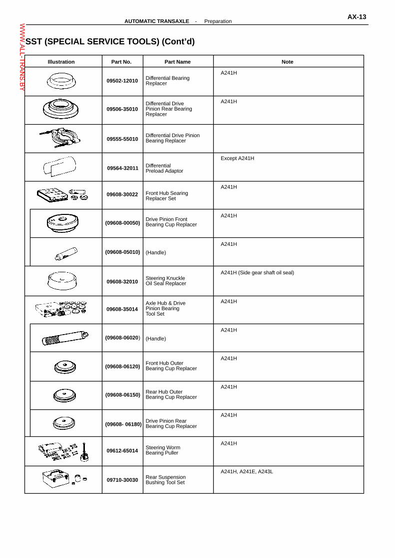
Illustration Part No. Part Name Note
09502-12010 Differential BearingReplacer
A241H
09506-35010Differential DrivePinion Rear BearingReplacer
A241H
09555-55010Differential Drive PinionBearing Replacer
09564-32011 DifferentialPreload Adaptor
Except A241H
09608-30022 Front Hub SearingReplacer Set
A241H
(09608-00050)Drive Pinion FrontBearing Cup Replacer
A241H
(09608-05010) (Handle)
A241H
09608-32010Steering KnuckleOil Seal Replacer
A241H (Side gear shaft oil seal)
09608-35014Axle Hub & DrivePinion BearingTool Set
A241H
(09608-06020) (Handle)
A241H
(09608-06120)Front Hub OuterBearing Cup Replacer
A241H
(09608-06150) Rear Hub OuterBearing Cup Replacer
A241H
(09608- 06180)Drive Pinion RearBearing Cup Replacer
A241H
09612-65014Steering WormBearing Puller
A241H
09710-30030 Rear SuspensionBushing Tool Set
A241H, A241E, A243L
SST (SPECIAL SERVICE TOOLS) (Cont’d)
-AUTOMATIC TRANSAXLE PreparationAX-13W
WW.ALL-TR
ANS.BY

Illustration Part No. Part Name Note
09031-00030 Pin Punch
Part Name Note
Feeler gauge Check major clearance.
Vernier caliper with depth gauge Check length of second coast brake piston rod.
Dial indicator with magnetic base Check piston stroke and end play of the output shaft.
Dial indicator Check inside diameter of major bushing.
Straight edge Check side clearance of oil pump.
Torque wrench
Illustration Part No. Part Name Note
(09710-03160) (Remover)
A241E, A243L
09950-00020 Bearing Remover
09950-00030 Bearing RemoverAttachment
A241H
SST (SPECIAL SERVICE TOOLS) (Cont’d)
RECOMMENDED TOOL
EQUIPMENT
AX-14-AUTOMATIC TRANSAXLE PreparationW
WW.ALL-TR
ANS.BY

Part Name Part No. Use etc.
Seal packing 1281, Three bond 1281 or equivalent 08826-00090
(A241H)Transfer left case × Differential lock control coverTransfer left case × Right caseTransfer left case × Inspection hole coverTransaxle housing × Transfer assembly
Adhesive 1324,Three bond 1324 or equivalent 08833-00070
Oil gallery cover tighten bolts(A241E: MR2, A241H)Torque converter mounting bolts
Adhesive 1344,Three bond 1344,Loctite 242 or equivalent 08833-00080 Transaxle housing tighten bolts
Adhesive 1131,Three bond 1131,Loctite 518 or equivalent 08833-00090
Transaxle rear cover × Transaxle caseTransaxle housing × Transaxle case(A241H)Transaxle housing × Transaxle caseTransaxle case × Rear cover
ItemCapacity
Classification
Liters US qts Imp. qts
Dry fillDrain and refill
Dry fillDrain and refill
A240L
A243L
Dry fillDrain and refill
8.03.3
8.53.5
7.02.9
ATF DEXRON� II
7.73.3
8.13.5
6.82.9
7.23.1
7.63.3
6.32.7
8.23.1
8.73.3
7.22.8
Transfer oil (A241H)
Dry fillDrain and refill
0.80.7
0.84.7
0.70.6 Recommended oil
Oil grade: API GL-5Viscosity: Above -18°C (0°F)SEA 75W-90, 80W-90 or 90Below -18°C (0°F)SEA 75W-90, 80W-90 or 80W
A241E
LUBRICANT
Automatic transmission fluid
Dry fillDrain and refill
A241H
Transaxle oil E50 (08885 - 80206) orequivalent
SSM (SPECIAL SERVICE MATERIALS)
-AUTOMATIC TRANSAXLE PreparationAX-15W
WW.ALL-TR
ANS.BY

Mark Class Mark Class
Hexagon head bolt
4
Bolt head No.
4-
5-
6-
7-
8-
9-
10-
11-
4T
5T
6T
7T
8T
9T
10T
11T
Stud bolt
No mark
4T
No mark 4T
Grooved
6T
Hexagon flange bolt
w/ washer hexagon bolt
No mark 4T
Hexagon head bolt Two
protrudinglines 5T
Hexagon flange bolt
w/ washer hexagon bolt
Two protrudinglines 6T Welded bolt
4T
Hexagon head bolt Three
protrudinglines 7T
Hexagon head bolt Four
protrudinglines 8T
STANDARD BOLT TORQUE SPECIFICATIONSHOW TO DETERMINE BOLT STRENGTH
-INTRODUCTION Standard Bolt Torque SpecificationsIN-7W
WW.ALL-TR
ANS.BY

ClassDiameter
mmPitchmm
Specified torque
Hexagon head bolt Hexagon flange bolt
kgf-cm ft-lbfN-m N-m kgf-cm ft-lbf
4T
6
8
10
12
14
16
1
1.25
1.25
1.25
1.5
1.5
55
130
260
480
760
1,150
5
12.5
26
47
74
115
48 in.-lbf
9
19
35
55
83
60
145
290
540
850
-
6
14
29
53
84
-
52 in.-lbf
10
21
39
61
-
5T
6
8
10
12
14
16
1
1.25
1.25
1.25
1.5
1.5
65
160
330
600
930
1,400
6.5
15.5
32
59
91
140
56 in.-lbf
12
24
43
67
101
65 in.-lbf
13
26
48
76
-
7.5
17.5
36
65
100
-
75
175
360
670
1,050
-
6T
6
8
10
12
14
16
1
1.25
1.25
1.25
1.5
1.5
80
195
400
730
1,100
1,750
69 in.-lbf
14
29
53
80
127
8
19
39
71
110
170
78 in.-lbf
15
32
59
90
-
9
21
44
80
125
-
90
210
440
810
1,250
-
7T
6
8
10
12
14
16
1
1.25
1.25
1.25
1.5
1.5
110
260
530
970
1,500
2,300
8
19
38
70
108
166
10.5
25
52
95
145
230
9
21
43
76
123
-
12
28
58
105
165
-
120
290
590
1,050
1,700
-
8T
8
10
12
1.25
1.25
1.25
300
620
1,100
29
61
110
22
45
80
33
68
120
24
50
90
330
690
1,250
9T
8
10
12
1.25
1.25
1.25
340
710
1,300
34
70
125
25
51
94
380
790
1,450
27
57
105
37
78
140
10T
8
10
12
1.25
1.25
1.25
390
800
1,450
38
78
140
28
58
105
42
88
155
31
64
116
430
890
1,600
11T
8
10
12
1.25
1.25
1.25
430
890
1,600
42
87
155
31
64
116
47
97
175
35
72
130
480
990
1,800
SPECIFIED TORQUE FOR STANDARD BOLTS
IN-8-INTRODUCTION Standard Bolt Torque SpecificationsW
WW.ALL-TR
ANS.BY

AT3369: Specified torque
♦ Oil Seal
39 (400, 29)
Drain Plug
Transfer Extension Housing
♦ Oil Seal
Shim
17 (170, 12)
Dawel Pin
Transfer Right Case
Oil Reserver
Oil PumpDriven Gear
Adjusting NutLock Plate
♦ Apply Gasket
♦ O-Ring
Transfer Right CaseRetainer
29 (300, 22)
♦ O-Ring
♦ O-Ring
Transfer InspectionHole Cover
Left Side BearingOuter Race
N-m (kgf-cm, ft-lbf)
Ring Gear Mounting Case andCenter Differential Case
♦ Apply GasketExtension HousingDust Deflector
TRANSFER (A241H)COMPONENTS
13 (130, 9)
♦ O-Ring
Mode Select Lever andRod
Oil Strainer
Lever GuideBearingAdjusting Nut
Right Side BearingOuter Race
44 (450, 33)
39 (400, 29)
Driven PinionBearing Cage
Plate Washer
♦ Apply Gasket
♦ Gasket
69 (700, 51)
Transfer Left Case
25 (260, 19)
♦ Non-reusable part
TR-2-TRANSFER (A241H) Component PartsW
WW.ALL-TR
ANS.BY

AT3351
AT3552
AT3353
AT8113
AT8480
REMOVAL OF COMPONENT PARTS1. REMOVE TRANSFER MODE SELECT LEVER AND
ROD
2. REMOVE EXTENSION HOUSING(a) Remove four bolts and extension housing.
(b) Remove the O-ring from the extension housing.
(c) Using a screwdriver, remove the oil seal.
3. REMOVE TRANSFER RIGHT CASE RETAINER(a) Remove the five bolts.
(b) Using a plastic hammer, remove the right caseretainer.
(c) Remove the O-ring and apply gasket from theright case retainer.
-TRANSFER (A241H) Removal of Component PartsTR-3W
WW.ALL-TR
ANS.BY

AT3360
AT3364
AT3362
AT3361
AT3354
4. REMOVE TRANSFER INSPECTION HOLE COVERRemove the three bolts and inspection hole cover.
5. CHECK PRELOAD(a) Using SST and a spring tension gauge, measure
the driven pinion preload of the backlash be-tween the driven pinion and ring gear.
SST 09326-2001 1Driven pinion preload (at starting):
8.8 - 13.7 N (0.9 - 1.4 kg, 2.0 - 3.1 Ib)(b) Using SST and a spring tension gauge, measure
the total preload.SST 09326-201 1Total preload (at starting):
Add driven pinion preload4.9 - 8.8 N (0.5 - 0.9 kg, 1.1 - 2.0 Ib)
SST
6. CHECK RING GEAR BACKLASHUsing a dial indicator, measure the ring gear backlash.Backlash: 0.13 - 0.18 mm (0.0051 - 0.0071 in.)
7. CHECK TOOTH CONTACT(See pages TR-34 , TR-35 )
8. REMOVE DRIVEN PINION BEARING CAGE(a) Remove the six bolts.
(b) Using a plastic hammer, remove the bearingcage.
(c) Remove the O-ring and the shims from the bear-ing cage.
9. REMOVE TRANSFER RIGHT CASERemove the ten bolts and right case.
TR-4-TRANSFER (A241H) Removal of Component PartsW
WW.ALL-TR
ANS.BY

AT3349
AT3350
AT8114
AT8092
SST
10. REMOVE CENTER DIFFERENTIAL ASSEMBLY
11. REMOVE APPLY GASKETRemove the apply gasket from the left case.
12. REMOVE OIL PUMP STRAINER AND OIL PUMPDRIVEN GEAR
13. REMOVE ADJUSTING NUT LOCK PLATE(a) Remove the bolt and nut lock plate from the right
case.
(b) Remove the O-ring from the bolt.
14. REMOVE DIFFERENTIAL RIGHT SIDE BEARINGOUTER PACE(a) Using SST, remove the adjusting nut and an oil
reserver from the right case.SST 09318-12010
AT4719
-TRANSFER (A241H) Removal of Component PartsTR-5W
WW.ALL-TR
ANS.BY

AT7764
AT3448
AT3357
(b) Using a brass bar, remove the outer race.
15. REMOVE DIFFERENTIAL LEFT SIDE BEARINGOUTER RACEUsing SST, remove the outer race and washer.SST 09308-00010
SST
16. REMOVE LEFT CASE OIL SEALUsing SST, remove the oil seal.SST 09308-00010
SST
TR-6-TRANSFER (A241H) Removal of Component PartsW
WW.ALL-TR
ANS.BY

AT7766
SST
AT7765
Drive Pinion Bearing CageCOMPONENTS
Front Side Bearing
Driven Pinion
Bearing CageRear Side Bearing
♦ Lock Nut
♦ Transfer Pinion Spacer
Plug
♦ O-RingAT3398Oil Strainer♦ Non-reusable part
DISASSEMBLY OF DRIVEN PINION BEARINGCAGE
1. REMOVE LOCK NUT(a) Using a chisel and hammer, unstake the lock nut.
(b) Using SST, remove the lock nut.SST 09326-2001 1NOTICE: Using the soft jaws, , hold the drive pinion ina vise.
-TRANSFER (A241H) Component Parts (Drive Pinion Bearing Cage)TR-7W
WW.ALL-TR
ANS.BY

AT8008
Strainer
Plug
AT7767
AT7768
AT7769
AT8089
Plug
2. REMOVE DRIVEN PINIONUsing a press, remove the driven pinion, rear sidebearing and spacer.
3. REMOVE FRONT SIDE BEARINGUsing a press and SST, remove the front side bearing.SST 09950-00020
SST
4. REMOVE BEARING OUTER RACESUsing a brass bar and hammer, remove the two bearingouter races.
5. REMOVE OIL STRAINER(a) Using low pressure air, remove the plug and oil
strainer.
(b) Remove the O-ring from the plug.
Strainer
X: Plug position
ASSEMBLY OF DRIVEN PINION BEARINGCAGE
1. INSTALL OIL STRAINER(a) Apply ATF to a new O-ring.
(b) Install a new O-ring to the plug.
(c) Install the oil strainer and plug.
TR-8-TRANSFER (A241H) Component Parts (Drive Pinion Bearing Cage)W
WW.ALL-TR
ANS.BY

AT7772
AT7773
AT7774
AT7775
SST
AT7770 AT7771
SST
Rear 2. INSTALL BEARING OUTER RACESUsing a press and SST, install the two bearing outerraces to the bearing cage.SST
Front side:09608-35014 (09608-06020, 09608-06120)
Rear side:09608-30022 (09608-05010, 09608-00050)
Front
SST
3. INSTALL DRIVEN PINION FRONT SIDE BEARINGUsing a press and SST, install the front side bearing.SST 09506-35010
SST
4. INSTALL SPACERInstall a new spacer to the driven pinion.
5. INSTALL DRIVEN PINION REAR SIDE BEARING(a) Install the bearing cage to the driven pinion.
(b) Using a press and SST, install the rear side bear-ing to the driven pinion.
SST 09506-35010
SST
6. ADJUST DRIVEN PINION PRELOAD(a) Using SST, torque a new nut.SST 09326-2001 1Torque: 98 N-m (1,000 kgf-cm, 72 ft-lbf)HINT: Use a torque wrench with a fulcrum length of 50cm (19.69 in.).
FulcrumLength
-TRANSFER (A241H) Component Parts (Drive Pinion Bearing Cage)TR-9W
WW.ALL-TR
ANS.BY

AT7777
AT7776
SST(b) Using a spring tension gauge and SST, measure
the preload.SST 09326-2001 1HINT: Turn the driven pinion right and left two or threetimes to allow the bearings to settle.Preload (at starting):
New bearing17.7 - 28.4 N (1.8 - 2.9 kg, 4.0 - 6.4 lb)
Reused bearing.8.8 - 13.7 N (0.9 - 1.4 kg, 2.0 - 3.1 lb)
� If preload is grater than specification, replacethe bearing spacer.
� If preload is less than specification, retightenthe nut 5-10 °at a time until the specified pre-load is rechecked.
If the maximum torque is exceed while retightening thenut, replace the bearing spacer and repeat the preloadprocedure.Do not back off the pinion nut to reduce the preload.Maximum torque: 216 N-m (2,200 kgf-cm, 159 ft-lbf)NOTICE: Using the soft jaws, , hold the bearing cagein a vise.
7. STAKE LOCK NUTUsing a pin punch and hammer, stake the nut.
TR-10-TRANSFER (A241H) Component Parts (Drive Pinion Bearing Cage)W
WW.ALL-TR
ANS.BY

AT8096
AT7781
♦ Non-reusable part
DifferentialSide Gear ShiftHolder
Hole Snap Ring
♦ Oil Seal
Holder Bearing
Transfer Right Case RetainerCOMPONENTS
Shaft Snap Ring
Transfer Right CaseRetainer
♦ Oil Seal
AT3373
DISASSEMBLY OF TRANSFER RIGHT CASE RE-TAINER
1. REMOVE OIL SEALUsing a screwdriver, remove the oil seal.
2. REMOVE SIDE GEAR SHAFT HOLDER(a) Using snap ring pliers, remove the snap ring.
-TRANSFER (A241H) Component Parts (Transfer Right Case Retainer)TR-1 1W
WW.ALL-TR
ANS.BY

AT7778
AT7780
SST
AT3342
AT7779
AT8009
(b) Remove the side gear shaft holder.
3. REMOVE HOLDER BEARING(a) Using snap ring pliers, remove the snap ring.
(b) Using a press, press out the bearing.
4. REMOVE OIL SEALUsing a screwdriver, remove the oil seal.
ASSEMBLY OF TRANSFER RIGHT CASERETAINER
1. INSTALL HOLDER BEARING(a) Using SST and a press, press in the holder bear-
ing.SST 09226-10010
TR-12-TRANSFER (A241H) Component Parts (Transfer Right Case Retainer)W
WW.ALL-TR
ANS.BY

AT8010
AT7781
AT3400
SST
AT3402
SST
AT7778
(b) Using snap ring pliers, install the snap ring.
2. INSTALL SIDE GEAR SHAFT HOLDER(a) Install the side gear shaft holder.
(b) Using snap ring pliers, install the snap ring.
3. INSTALL OIL SEAL(Left side oil seal)(a) Coat a new oil seal lip with MP grease.
(b) Using a hammer and SST, drive in a oil seal.SST 09316-60010 (09316-00010, 09316-00040)Oil seal depth: 0 mm (0 in.)
(Right side oil seal)(a) Coat a new oil seal lip with MP grease.
(b) Using a hammer and SST, drive in a oil seal.SST 09608-32010, 09608-35014 (09608-06020)Oil seal depth: 0 mm (0 in.)
-TRANSFER (A241H) Component Parts (Transfer Right Case Retainer)TR-13W
WW.ALL-TR
ANS.BY

N-m (kgf-cm, ft-lbf)
AT8063
♦ Non-reusable part
: Specified torque
Compression Spring
10 (100, 7)
10 (100, 7)
Level Gauge Guide Plate
Oil PumpDriven Rotor
Transfer Right CaseCOMPONENTS
25 (250, 18)
♦ O-Ring
Oil PumpDrive Rotor
Oil PumpCover
Relief Valve
AT3372
DISASSEMBLY OF TRANSFER RIGHT CASE
1. INSPECT OIL PUMP OPERATIONCheck that the oil pump turns smoothly with oil pumpdriven gear.
2. REMOVE OIL PUMP COVERRemove the three bolts and the cover.
AT8068
TR-14-TRANSFER (A241H) Component Parts (Transfer Right Case)W
WW.ALL-TR
ANS.BY

AT8046
AT8066
AT8046
MatchmarksAT8080
AT8067
3. REMOVE OIL PUMP DRIVE ROTOR AND DRIVENROTOR
4. REMOVE RELIEF VALVERemove the relief valve and a spring.
5. REMOVE LEVEL GAUGE GUIDE PLATE
ASSEMBLY OF TRANSFER RIGHT CASE
1. INSTALL LEVEL GAUGE GUIDE PLATETorque: 10 N-m (100 kgf-cm, 7 ft-lbf)
2. INSTALL RELIEF VALVEInstall the relief valve and a spring.
3. INSTALL OIL PUMP DRIVE ROTOR AND DRIVENROTORAlign the matchmarks on the drive rotor and the drivenrotor.
-TRANSFER (A241H) Component Parts (Transfer Right Case)TR-15W
WW.ALL-TR
ANS.BY

AT8063
AT8068
4. INSTALL OIL PUMP COVERTorque the three bolts evenly.Torque: 10 N-m (100 kgf-cm, 7 ft-lbf)
5. CHECK OPERATION OF OIL PUMPInstall the oil pump driven gear to the drive rotor, checkthat the drive rotor turns smoothly.
TR-16-TRANSFER (A241H) Component Parts (Transfer Right Case)W
WW.ALL-TR
ANS.BY

♦ Non-reusable part
N-m (kgf-cm, ft-lbf)
Side Gear Thrust Washer
Differential Pinion Holder
Differential Pinion Thrust Washer
Thrust Washer
Conical SpringWasher
Spacer
97 (984, 71)
Shaft SnapRing
TransferRing Gear
Ring Gear MountingRight Case
♦ Right Case Bearing
COMPONENTS
Ring Gear Mounting Case and Center Differential Case
♦ O-Ring
Ring Gear MountingLeft Case
♦ Left CaseBearing
Oil Pump Drive Gear
Shaft SnapRing
Differential SideRight Gear
Center Differential Case
Differential Pinion
Differential Pinion Shaft
Differential Side Left Gear
: Specified torqueAT3371
DISASSEMBLY OF RING GEAR MOUNTINGCASE AND CENTER DIFFERENTIAL CASE
1. REMOVE OIL PUMP DRIVE GEAR(a) Using a screwdriver, remove the shaft snap ring.
AT8294
-TRANSFER (A241H) Component Parts(Ring Gear Mounting Case and Center Differential Case)
TR-17WWW.ALL-TR
ANS.BY
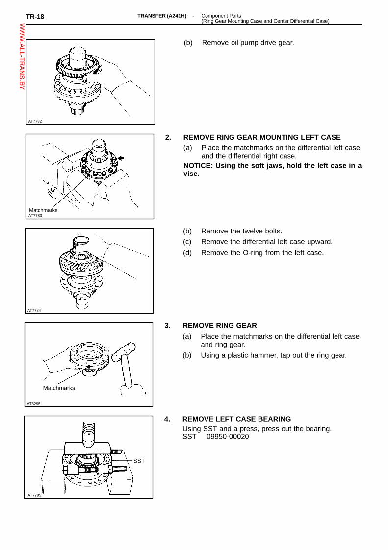
AT7785
AT7782
Matchmarks
AT7784
AT8295
(b) Remove oil pump drive gear.
2. REMOVE RING GEAR MOUNTING LEFT CASE(a) Place the matchmarks on the differential left case
and the differential right case.NOTICE: Using the soft jaws, hold the left case in avise.
(b) Remove the twelve bolts.
(c) Remove the differential left case upward.
(d) Remove the O-ring from the left case.
3. REMOVE RING GEAR(a) Place the matchmarks on the differential left case
and ring gear.
(b) Using a plastic hammer, tap out the ring gear.
Matchmarks
4. REMOVE LEFT CASE BEARINGUsing SST and a press, press out the bearing.SST 09950-00020
SST
AT7783
TR-18 -TRANSFER (A241H) Component Parts(Ring Gear Mounting Case and Center Differential Case)W
WW.ALL-TR
ANS.BY

AT7786
AT7787
AT7788
5. REMOVE THRUST WASHER
6. REMOVE CENTER DIFFERENTIAL CASE AS-SEMBLY
7. DISASSEMBLE CENTER DIFFERENTIAL CASE(a) Using snap ring pliers, remove the shaft snap
ring.
(b) Remove the spacer.
AT7789
-TRANSFER (A241H) Component Parts(Ring Gear Mounting Case and Center Differential Case)
TR-19WWW.ALL-TR
ANS.BY
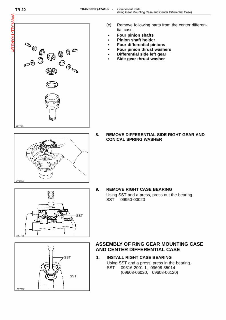
AT8354
AT7791
AT7792
SST
AT7790
(c) Remove following parts from the center differen-tial case.
� Four pinion shafts� Pinion shaft holder� Four differential pinions� Four pinion thrust washers� Differential side left gear� Side gear thrust washer
8. REMOVE DIFFERENTIAL SIDE RIGHT GEAR ANDCONICAL SPRING WASHER
9. REMOVE RIGHT CASE BEARINGUsing SST and a press, press out the bearing.SST 09950-00020
SST
ASSEMBLY OF RING GEAR MOUNTING CASEAND CENTER DIFFERENTIAL CASE
1. INSTALL RIGHT CASE BEARINGUsing SST and a press, press in the bearing.SST 09316-2001 1, 09608-35014
(09608-06020, 09608-06120)SST
TR-20 -TRANSFER (A241H) Component Parts(Ring Gear Mounting Case and Center Differential Case)W
WW.ALL-TR
ANS.BY

AT7793
AT7790
AT3310
FA1126
100°C (212°F)
2. INSTALL LEFT CASE BEARINGUsing SST and a press in the left case.SST 09316-12010, 09608-35014
(09608-06020, 09608-06120)SST
3. INSTALL RING GEAR(a) Clean the contact surface of the ring gear mount-
ing left case.
(b) Heat the ring gear to about 100°C (212°F) in anoil bath.
NOTICE: Do not heat the ring gear about gear above110°C (230°F)(c) Clean the contact surface of the ring gear with
cleaning solvent.
(d) Align the matchmarks and quickly install the ringgear on the ring gear mounting left case.
4. CHECK AND ADJUST CENTER DIFFERENTIAL SIDEGEAR BACKLASH(a) Install following parts to the center differential
case:� Side gear thrust washer� Differential side left gear� Four pinion thrust washers� Four differential pinions� Pinion shaft holder� Four pinion shafts
(b) Install spacer toward to as shown.
-TRANSFER (A241H) Component Parts(Ring Gear Mounting Case and Center Differential Case)
TR-21WWW.ALL-TR
ANS.BY

Mark Thickness mm (in.) Mark Thickness mm (in.)
A
B
C
D
E
1.00 (0.0394)
1.05 (0.0413)
1.10 (0.0433)
1.15 (0.0453)
1.20 (0.0472)
F
G
H
J
1.25 (0.0492)
1.30 (0.0512)
1.35 (0.0531)
1.40 (0.0551)
AT7788
AT7795
AT7787
AT7794
(c) Using a dial indicator, measure the backlash of onepinion gear while holding the side gear toward thecase.
Standard backlash: 0.06 - 0.22 mm(0.0024 - 0.0087 in.)
HINT: Do not mount the surface of center differential casewhich contacts with bushing in a vise.Referring to the table bellow, select the thrust washerwhich will ensure that the backlash is within specification.Try to select a washer of the same size.
(d) Using snap ring pliers, install the shaft snap ring.
5. CHECK AND ADJUST CENTER DIFFERENTIALSIDE GEAR THRUST CLEARANCE.(a) Install differential side right gear.HINT: Do not install the conical spring washer.
(b) Install center differential case.
TR-22 -TRANSFER (A241H) Component Parts(Ring Gear Mounting Case and Center Differential Case)W
WW.ALL-TR
ANS.BY
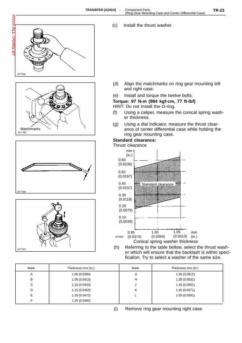
MatchmarksAT7783
AT7796
AT7797
Mark Thickness mm (in.) Mark Thickness mm (in.)
A
B
C
D
E
F
1.00 (0.0394)
1.05 (0.0413)
1.10 (0.0433)
1.15 (0.0453)
1.20 (0.0472)
1.25 (0.0492)
G
H
J
K
L
1.30 (0.0512)
1.35 (0.0531)
1.40 (0.0551)
1.45 (0.0571)
1.50 (0.0591)
AT7786
mm(in.)
0.60(0.0236)
AT3460
(h) Referring to the table bellow, select the thrust wash-er which will ensure that the backlash is within speci-fication. Try to select a washer of the same size.
0.95(0.0374)
1.00(0.0394)
1.05(0.0413)
Conical spring washer thickness
(c) Install the thrust washer.
(d) Align the matchmarks on ring gear mounting leftand right case.
(e) Install and torque the twelve bolts.Torque: 97 N-m (984 kgf-cm, 77 ft-lbf)HINT: Do not install the O-ring.(f) Using a caliper, measure the conical spring wash-
er thickness.
(g) Using a dial indicator, measure the thrust clear-ance of center differential case while holding thering gear mounting case.
Standard clearance:Thrust clearance
mm(in.)
0.50(0.0197)
Standard clearance0.40(0.0157)
0.30(0.0118)
0.20(0.0079)
0.10(0.0039)
(i) Remove ring gear mounting right case.
-TRANSFER (A241H) Component Parts(Ring Gear Mounting Case and Center Differential Case)
TR-23WWW.ALL-TR
ANS.BY

MatchmarksAT7783
AT7798
AT7787
AT7799
AT7786
6. INSTALL DIFFERENTIAL SIDE GEAR AND CONICALSPRING WASHERHINT: Be careful not to mistake the direction of conicalspring washer.
7. INSTALL CENTER DIFFERENTIAL CASE
8. INSTALL THRUST WASHER (Previously selected)
9. INSTALL RING GEAR MOUNTING LEFT CASE(a) Coat the new O-ring with. ATF, and install it onto
the left case.
(b) Align the matchmarks on the right and left case.
(c) Install and torque the twelve bolts.Torque: 984 kg-cm (71 ft-lb, 97 N-m)NOTICE: Using the soft jaws, hold the left case in avise.
10. INSTALL OIL PUMP DRIVE GEAR(a) Install the oil pump drive gear.
TR-24 -TRANSFER (A241H) Component Parts(Ring Gear Mounting Case and Center Differential Case)W
WW.ALL-TR
ANS.BY

(b) Install the shaft snap ring.
AT7800
-TRANSFER (A241H) Component Parts(Ring Gear Mounting Case and Center Differential Case)
TR-25WWW.ALL-TR
ANS.BY

AT3370
: Specified torque
Clutch Control ValveSleeve Cover
Clutch ControlValve
Clutch Control ValveSpring Retainer
Straight Pin
TransferShift Lever
♦ Spacer
Transfer ShiftLever Shaft
♦ O-Ring
Straight Pin
Differential ControlSolenoid
13 (130, 9)
29 (300, 22)
Differential ControlShift Fork
Solenoid Oil Strainer
Transfer Left CaseCOMPONENTS
�Plug
7.1 (73, 63 in.-lbf)
♦ O-Ring
Compression Spring
Ball
♦ Oil Seal
Differential ControlShift Sleeve
Differential ControlShift Fork Shaft
Differential Control ClutchPressure Apply Tube
Clutch ControlValve Sleeve
CompressionSpring
N-m (kgf-cm, ft-lbf)
♦ Non-reusable part�Precoated part
17 (170, 12)
TR-26-TRANSFER (A241H) Component Parts (Transfer Left Case)W
WW.ALL-TR
ANS.BY

AT8081
AT8085
AT8065
AT8060
AT8011
DISASSEMBLY OF TRANSFER LEFT CASE
1. REMOVE APPLY TUBE
2. REMOVE CENTER DIFFERENTIAL CONTROL SOLE-NOID(a) Remove the plug, compression spring and ball.
(b) Remove a bolt and solenoid.
(c) Remove two O-rings from the solenoid.
3. REMOVE DIFFERENTIAL CONTROL SHIFT FORKSHAFT, SHIFT FORK SLEEVE
4. REMOVE TRANSFER SHIFT LEVER(a) Wing a screwdriver and hammer, cut the spacer.
-TRANSFER (A241H) Component Parts (Transfer Left Case)TR-27W
WW.ALL-TR
ANS.BY

AT8064
AT8243
AT8244
AT8245
AT8054
(b) Using a pin punch and hammer, drive out thestraight pin.
(c) Remove the shift lever shaft and shift lever.
(d) Using a screwdriver, remove the oil seal.
5. REMOVE PLUGS(a) Remove two plugs.
(b) Remove the O-rings from each plugs.
6. REMOVE DIFFERENTIAL CONTROL VALVE(a) Remove the control valve sleeve cover.
TR-28-TRANSFER (A241H) Component Parts (Transfer Left Case)W
WW.ALL-TR
ANS.BY

AT8257
AT8258
AT8259
AT3311
Seal Packing
AT8256
(b) Remove straight pin and control valve sleeve.
(c) Remove following parts from the control valvesleeve:
� Valve spring retainer� Compression spring� Control valve� Solenoid oil strainer
ASSEMBLY OF TRANSFER LEFT CASE
1. INSTALL DIFFERENTIAL LOCK CLUTCH CONTROLVALVE(a) Install following parts to the control valve sleeve:� Solenoid oil strainer� Control valve� Compression spring� Valve spring retainer
(b) Install the control valve sleeve and straight pin.
(c) Apply seal packing to the rear cover as shown.Seal packing: Part No. 08826 - 00090 THREE BOND
1281, or equivalentHINT: Install the cover as soon as the seal packing is ap-plied.
-TRANSFER (A241H) Component Parts (Transfer Left Case)TR-29W
WW.ALL-TR
ANS.BY
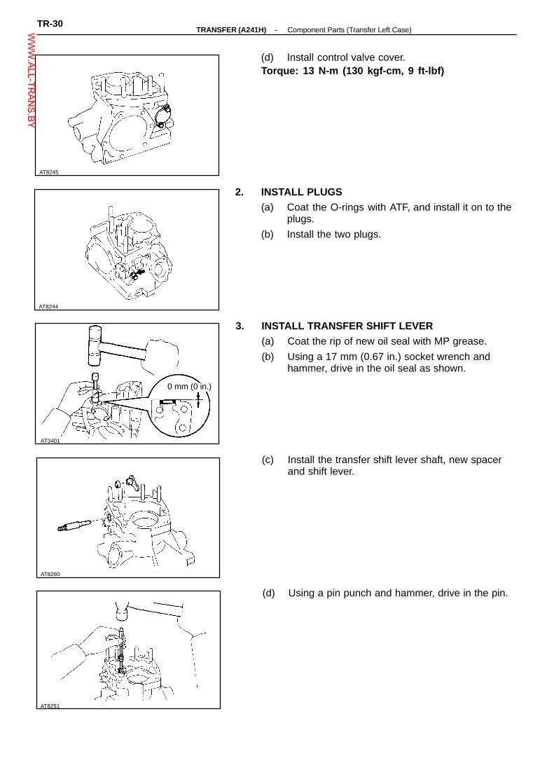
AT8245
AT8244
AT3401
AT8251
AT8260
(d) Install control valve cover.Torque: 13 N-m (130 kgf-cm, 9 ft-lbf)
2. INSTALL PLUGS(a) Coat the O-rings with ATF, and install it on to the
plugs.
(b) Install the two plugs.
3. INSTALL TRANSFER SHIFT LEVER(a) Coat the rip of new oil seal with MP grease.
(b) Using a 17 mm (0.67 in.) socket wrench andhammer, drive in the oil seal as shown.
0 mm (0 in.)
(c) Install the transfer shift lever shaft, new spacerand shift lever.
(d) Using a pin punch and hammer, drive in the pin.
TR-30-TRANSFER (A241H) Component Parts (Transfer Left Case)W
WW.ALL-TR
ANS.BY

AT8252
AT8266
AT8254
AT8255
AT8253
(e) Slide the spacer as shown.
(f) Using a pin punch and hammer, stake the spacer.
4. INSTALL DIFFERENTIAL CONTROL SHIFT FORK,SLEEVE AND SHIFT FORK SHAFTHINT: Engaged shift fork and transfer shift lever.
5. INSTALL CENTER DIFFERENTIAL CONTROLSOLENOID(a) Install the ball and compression spring.
(b) Coat the two new O-rings with ATF, install it on to thesolenoid.
(c) Install the solenoid.
(d) Install and tighten the plug and the bolt.Torque: Bolt 13 N-m (130 kgf-cm, 9 ft-lbf)
Plug 29 N-m (300 kgf-cm, 22 ft-lbf)Plug
6. INSTALL APPLY TUBETap the tubes with a plastic hammer to install then intothe positions indicated in the illustration.NOTICE: Be careful not to bend or damage the tubes.
-TRANSFER (A241H) Component Parts (Transfer Left Case)TR-31W
WW.ALL-TR
ANS.BY

AT8353
AT8115
AT8267
AT8268
AT4720
Adjusting Nut
ASSEMBLY OF COMPONENT PARTS
1. INSTALL LEFT CASE SIDE(a) Install the plate washer.
(b) Using SST and a press, press in the outer race.SST 09316-60010 (09316-00010, 09316-00060)
SST
2. INSTALL RIGHT CASE SIDE(a) Using SST and a press, press in outer race as
shown.SST 09316-60010 (09316-00010, 09316-00060)
SST
(b) Install the bearing adjusting nut and oil reserver,until it touch the outer race.
Oil Reserver
3. ADJUSTING GEAR BACKLASH(a) Install the shim to the driven pinion bearing cage
assembly.HINT: First install a shim of the some thickness as be-fore.
TR-32-TRANSFER (A241H) Component Parts (Transfer Left Case)W
WW.ALL-TR
ANS.BY

AT3363
AT3364
Mark Thickness Mark Thickness
71 2.13 (0.0839) 83 2.49 (0.0980)
72 2.16 (0.0850) 84 2.52 (0.0992)
73 2.19 (0.0862) 85 2.55 (0.1004)
74 2.22 (0.0874) 86 2.58 (0.1016)
75 2.25 (0.0886) 87 2.61 (0.1028)
76 2.28 (0.0898) 88 2.64 (0.1039)
77 2.31 (0.0909) 89 2.67 (0.1051)
78 2.34 (0.0921) 90 2.70 (0.1063)
79 2.37 (0.0933) 91 2.73 (0.1075)
80 2.40 (0.0945) 92 2.76 (0.1087)
81 2.43 (0.0957) 93 2.79 (0.1098)
82 2.46 (0.0969) 94 2.82 (0.1110)
AT3362
Plate washer thickness mm (in.)
(b) Install driven pinion cage.Torque: 39 N-m (400 kgf-cm, 29 ft-lbf)HINT: Do not install the O-ring.
(c) Install ring gear mounting case and center differ-ential case.
(d) Using a dial indicator, measure the ring gearbacklash.
Backlash: 0.13 - 0.18 mm (0.0051 - 0.0071 in.)
(e) Referring to the table bellow, select the platewasher which will ensure that the backlash is within specification.
Try select a washer of the same size.
-TRANSFER (A241H) Component Parts (Transfer Left Case)TR-33W
WW.ALL-TR
ANS.BY

AT3361
AT3360
AT3308
SST
AT3359
AT3358
4. ADJUST TOTAL PRELOAD(a) Install the transfer right case.HINT: Do not apply seal packing and do not installgasket.Torque: 44 N-m (450 kgf-cm, 33 ft-lbf)
(b) Using SST and a spring tension gage, measurethe total preload.
SST 09326-2001 1Preload (at starting):
New bearingAdd driven pinion preload
12.7 - 13.7 N (1.3 - 1.4 kg, 2.9 - 3.1 lb)Reused bearingAdd driven pinion preload
4.9 - 8.8 N (0.5 - 0.9 kg, 1.1 - 2.0 lb)
SST
(c) Adjusting total preload by tightening the adjustingnut with SST.
SST 09318-12010HINT: Measure the preload while tightening the bearingadjusting nut a little at a time.
5. CHECK RING GEAR BACKLASH(a) Using a dial indicator, measure the ring gear
backlash.Backlash: 0.13 - 0.18 mm (0.0051 - 0.0071 in.)(b) When the backlash is outside the standard value,
select a different plate washer to the one se-lected step 3. Again adjust the backlash and totalpreload.
6. CHECK TOOTH CONTACT(a) Coat 3 or 4 teeth at different position on the ring
gear with red lead.
(b) Rotate the ring gear, inspect the teeth pattern.
TR-34-TRANSFER (A241H) Component Parts (Transfer Left Case)W
WW.ALL-TR
ANS.BY

Mark Thickness Mark Thickness
A
B
C
D
E
0.30 (0.0118)
0.33 (0.0130)
0.36 (0.0142)
0.39 (0.0154)
0.42 (0.0165)
F
G
H
J
K
0.45 (0.0177)
0.48 (0.0189)
0.51 (0.0201)
0.54 (0.0213)
0.57 (0.0224)
AT3361
AT3363
AT3397
Flank Contact
Select an adjusting shim that will bring the drivenpinion closer to the ring gear.
Fase Contact
mm (in.)
Heel Contact
Proper Contact
Toe Contact
Select an adjusting shim that will shift the drivenpinion away from the ring gear.
(c) If the teeth are not connecting properly, again theproper shim and plate.
7. REMOVE TRANSFER RIGHT CASERemove the ten bolts and transfer right case.
8. REMOVE RING GEAR MOUNTING CASE AND CEN-TER DIFFERENTIAL CASE
-TRANSFER (A241H) Component Parts (Transfer Left Case)TR-35W
WW.ALL-TR
ANS.BY

AT3357
AT3415
3 mm
AT8115
AT8267
AT3362
9. REMOVE DRIVEN PINION BEARING CAGE
10. REMOVE LEFT CASE BEARING OUTER RACE ANDPLATE WASHER
SST
11. INSTALL OIL SEAL(a) Using SST, install a new oil seal as shown.SST 09316-60010 (09316-00010, 09316-00030)Oil seal depth: 3 mm (0.12 in.)(b) Coat the lip of oil seal with MP grease.
12. INSTALL LEFT CASE BEARING OUTER RACE(a) Install the plate washer. (previously selected)
(b) Using SST and a press, press in the outer race.SST 09316-60010 (09316-00010, 09316-00060)
SST
TR-36-TRANSFER (A241H) Component Parts (Transfer Left Case)W
WW.ALL-TR
ANS.BY

AT3363
AT3309
Apply Gasket
AT8114
AT3450
Seal Packing
AT3362
13. INSTALL DRIVEN PINION BEARING CAGE(a) Coat the O-ring with gear oil, and install it to the
bearing cage.
(b) Install shim (previously selected) and bearingcage assembly.
Torque: 39 N-m (400 kgf-cm, 29 ft-lbf)
14. INSTALL RING GEAR MOUNTING CASE AND CEN-TER DIFFERENTIAL CASE
15. INSTALL TRANSFER RIGHT CASE(a) Install a new apply gasket to the left case.
(b) Install oil pump strainer and driven gear to theright case.
(c) Apply seal packing to the left case as shown in thefigure.
Seal packing: Part No. 08826 - 00090 THREE BOND1281 or equivalent
HINT: Install the right case as soon as the packing is ap-plied.
-TRANSFER (A241H) Component Parts (Transfer Left Case)TR-37W
WW.ALL-TR
ANS.BY

AT8113
AT3361
AT3356
AT3354
AT3312
(d) Install right case and ten bolts.Torque: 44 N-m (459 kgf-cm, 33 ft-lbf)
16. CHECK TOTAL PRELOAD(See page TR-34 )
17. INSTALL ADJUSTING NUT LOCK PLATEInstall the lock plate so that projection from the lockplate fits properly into the groove of the adjusting nut.
18. INSTALL TRANSFER INSPECTION HOLE COVER(a) Apply seal packing to the left case as shown in the
figure.Seal packing: Parts No. 08826 - 00090 THREE BOND
1281 or equivalentHINT: Install the cover as soon as the seal packing is ap-plied.
SealPacking
(b) Install hole cover.Torque: 17 N-m (170 kgf-cm, 12 ft-lbf)
19. INSTALL TRANSFER RIGHT CASE RETAINER(a) Coat a O-ring with gear oil, and install it and new
apply gasket.
TR-38-TRANSFER (A241H) Component Parts (Transfer Left Case)W
WW.ALL-TR
ANS.BY

AT8269
SST
AT3352
AT3351
AT3353
(b) Install case Retainer.Torque: 25 N-m (260 kgf-cm, 19 ft-lbf)
20. INSTALL EXTENSION HOUSING(a) Using SST and a hammer, drive in a new oil seal
as shown.SST 09325-20010Oil seal depth: 0.1 - 0.9 mm (0.004 - 0.035 in.)(b) Coat the lip of the oil seal with MP grease.0.1 - 0.9 mm
(c) Coat a new O-ring with gear oil.
(d) Install dust deflector and O-ring to the extensionhousing.
(e) Install extension housing to the drive pinion bear-ing cage.
Torque: 25 N-m (260 kgf-cm, 19 ft-lbf)
21. INSTALL TRANSFER MODE SELECT LEVER ANDROD(a) Install the lever, rod and lever guide.Torque: 13 N-m (130 kgf-cm, 9 ft-lbf)(b) Install the bolt while setting the lever as shown.Torque: 13 N-m (130 kgf-cm, 9 ft-lbf)
-TRANSFER (A241H) Component Parts (Transfer Left Case)TR-39W
WW.ALL-TR
ANS.BY