aberrations aberrations of lenses analogue to holographic model aberrations in holography ...
TRANSCRIPT

Triple Take Holographics
Dinesh Padiyar
Aberrationsin Holography
ISDH 2012
Triple Take Holographics Dinesh Padiyar
Aberrations Aberrations of Lenses Analogue to Holographic Model Aberrations in Holography Implications in the aberration equations Experimental Demonstration
Triple Take Holographics Dinesh Padiyar
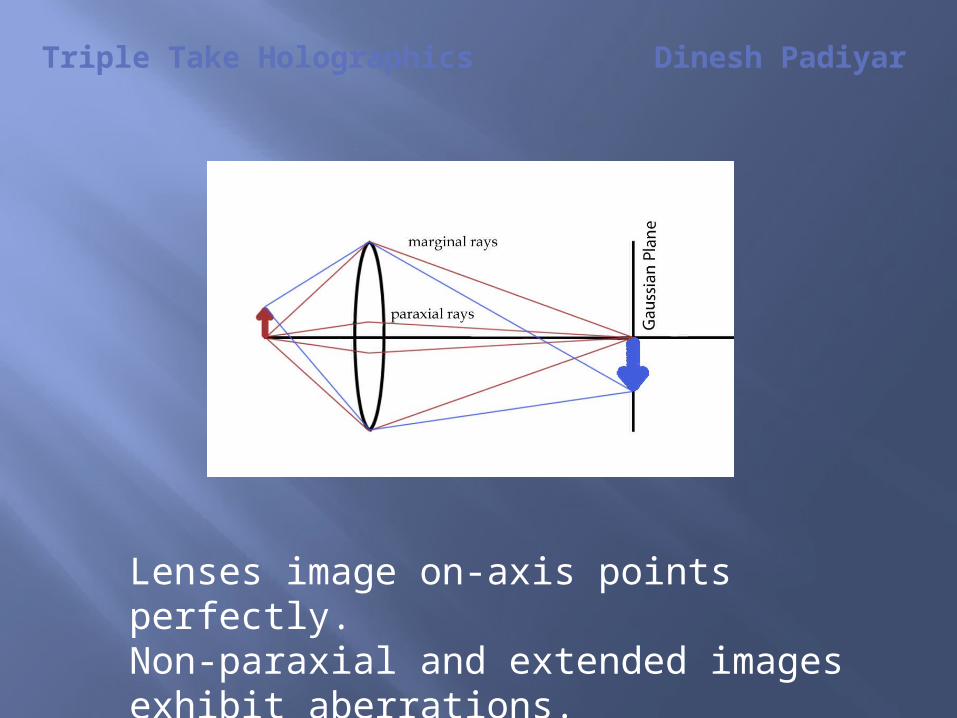
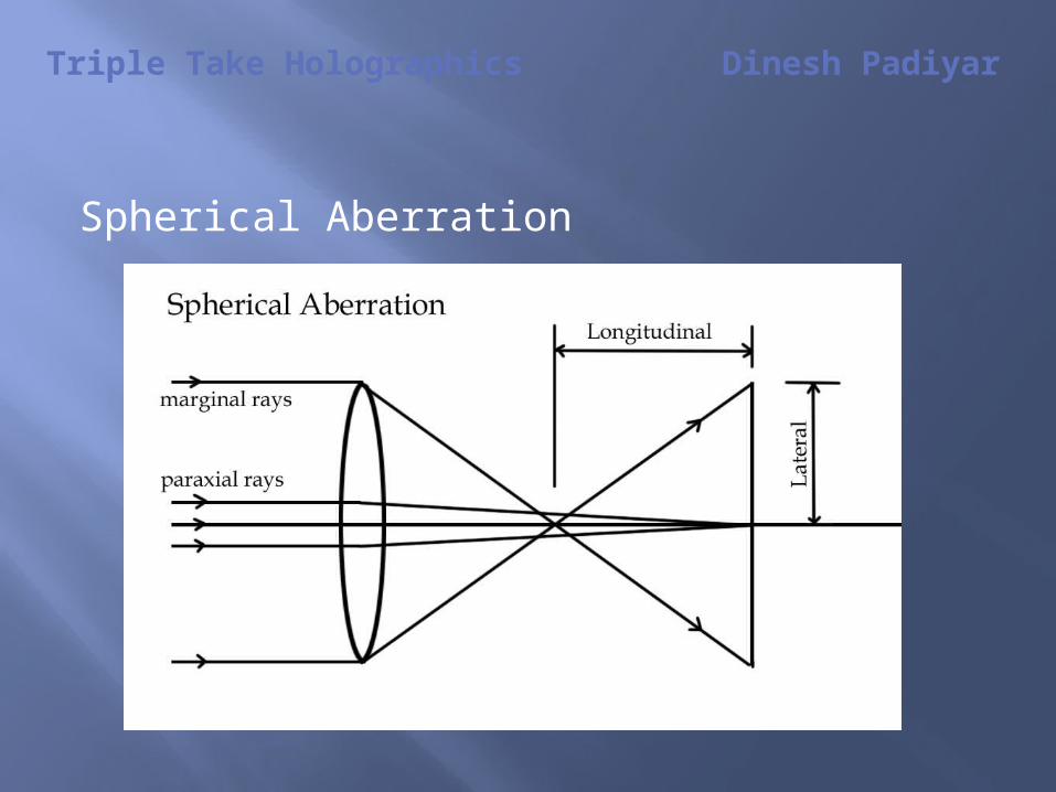
Lenses image on-axis points perfectly. Non-paraxial and extended images exhibit aberrations.
Triple Take Holographics Dinesh Padiyar
An aberration in an imaging system is defined as any distortion of an image due to imperfections in the imaging system.
In standard optics, these occur for non-axial object points and extremal rays.
Note that a mis-aligned optic effectively creates an off-axis point.
Triple Take Holographics Dinesh Padiyar
There are 5 standard aberrations known as the Seidel Aberrations:
o Spherical Aberrationo Comao Astigmatismo Petzval (Field)(Curvatureo Distortion
Triple Take Holographics Dinesh Padiyar
Spherical Aberration

Triple Take Holographics Dinesh Padiyar
Coma
Triple Take Holographics Dinesh Padiyar
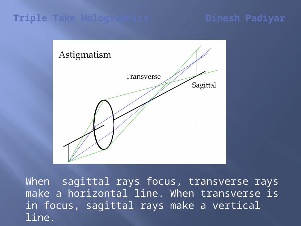
When sagittal rays focus, transverse rays make a horizontal line. When transverse is in focus, sagittal rays make a vertical line.
Triple Take Holographics Dinesh Padiyar
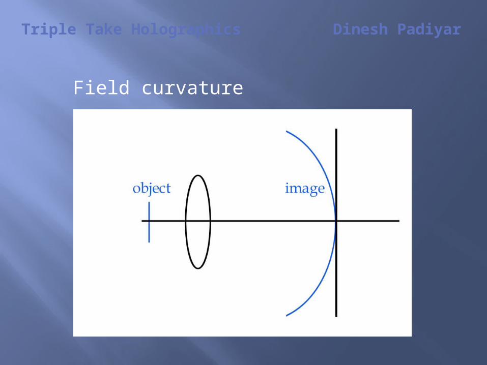
Field curvature
Triple Take Holographics Dinesh Padiyar
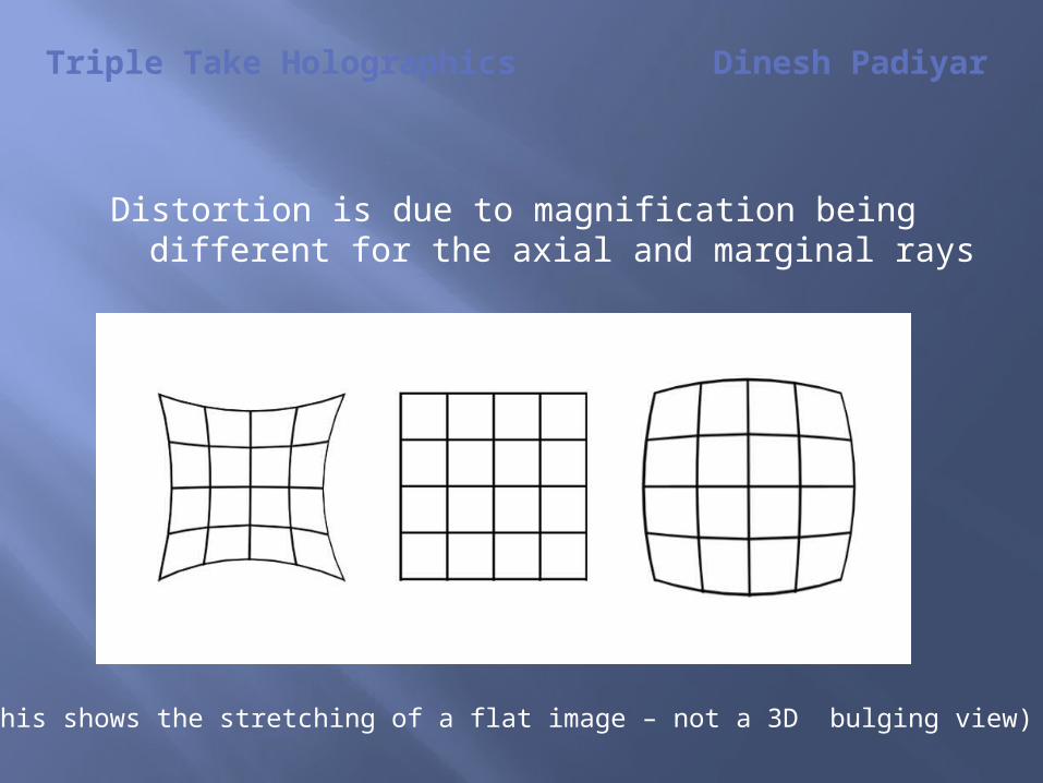
Distortion is due to magnification being different for the axial and marginal rays
(This shows the stretching of a flat image – not a 3D bulging view)
Triple Take Holographics Dinesh Padiyar
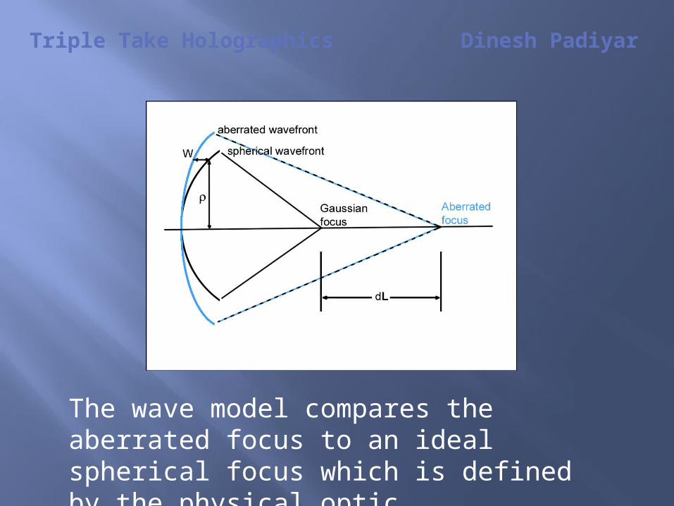
The wave model compares the aberrated focus to an ideal spherical focus which is defined by the physical optic.
Triple Take Holographics Dinesh Padiyar
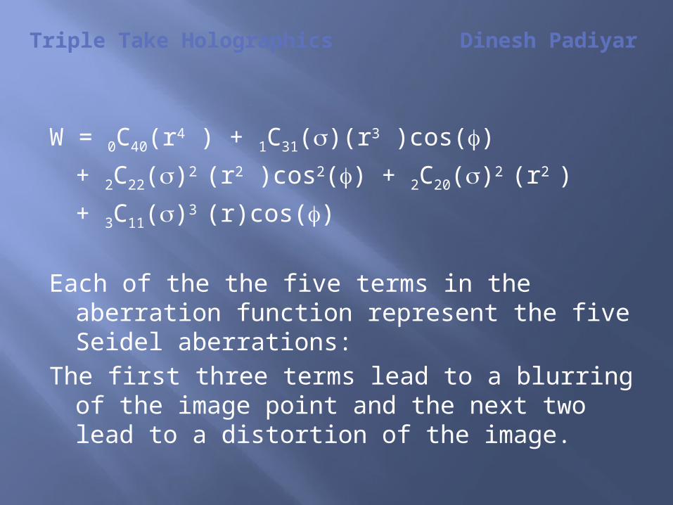
W = 0C40(r4 ) + 1C31()(r3 )cos()
+ 2C22()2 (r2 )cos2() + 2C20()2 (r2 )
+ 3C11()3 (r)cos()
Each of the the five terms in the aberration function represent the five Seidel aberrations:
The first three terms lead to a blurring of the image point and the next two lead to a distortion of the image.
Triple Take Holographics Dinesh Padiyar
The Holographic Model
In order to show a correlation between holography and conventional lenses, an equivalent “focal
length”, fR for the hologram may be derived from the reconstructed phase wavefront. This is allowable
insofar as the reconstructed phase wavefront is also a converging spherical wavefront and maybe
thought of as the “reference sphere”.
Triple Take Holographics Dinesh Padiyar
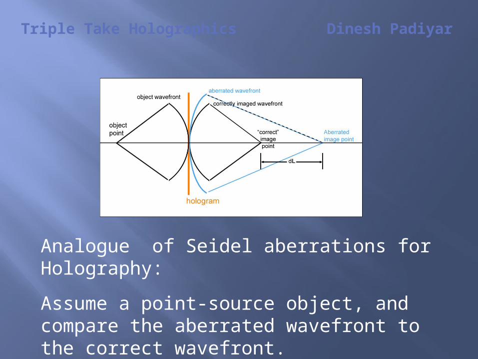
Analogue of Seidel aberrations for Holography:
Assume a point-source object, and compare the aberrated wavefront to the correct wavefront.
Triple Take Holographics Dinesh Padiyar
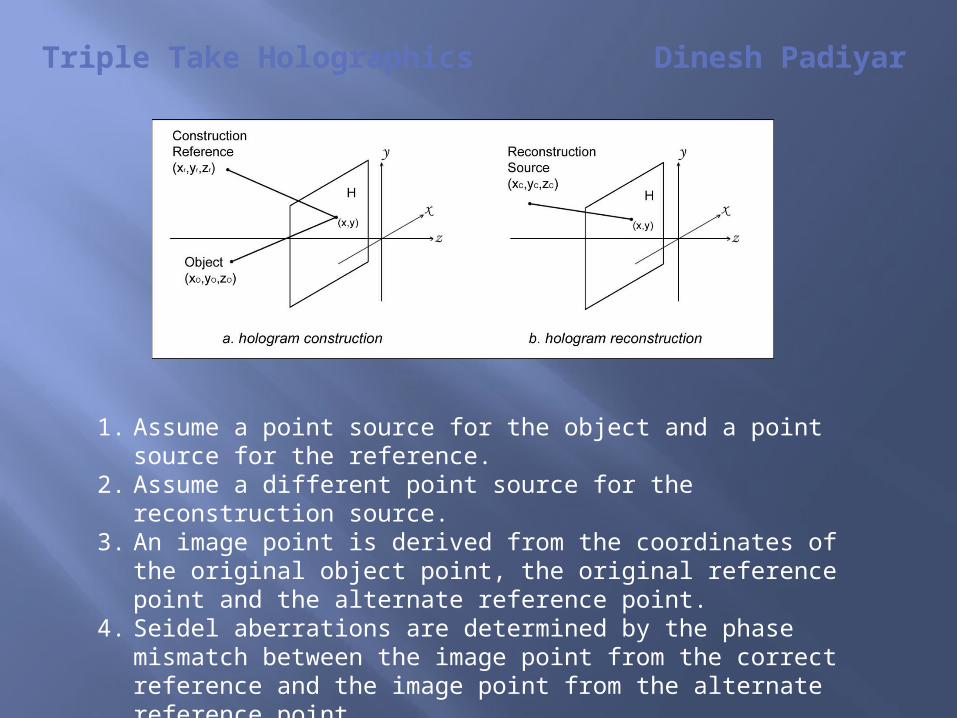
1. Assume a point source for the object and a point source for the reference.
2. Assume a different point source for the reconstruction source.
3. An image point is derived from the coordinates of the original object point, the original reference point and the alternate reference point.
4. Seidel aberrations are determined by the phase mismatch between the image point from the correct reference and the image point from the alternate reference point.

Triple Take Holographics Dinesh Padiyar
The Derivation:The emerging reconstructed phase wavefront is the
sum of the recorded phases and the phase of the reconstruction wave.
Q = fc +/- fr +/- fo Signs indicate original (virtual) image or conjugate (real).
The general expression from a point G for a spherical wave is
= 2{[(x - xg)2 + (y-yg)2 + zg 2]1/2
– [xg2 + yg
2 + zg2]1/2}
Substituting this into the above, with the specific coordinates and replacing the general coordinates, an exact expression is obtained for the phase at the hologram plane.
Triple Take Holographics Dinesh Padiyar
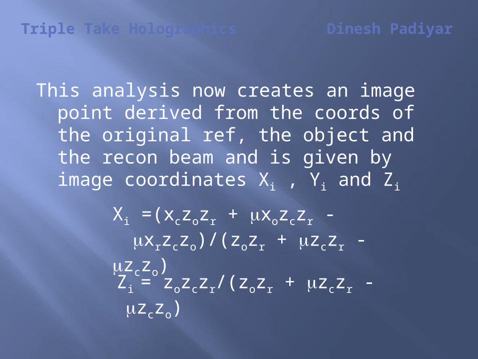
This analysis now creates an image point derived from the coords of the original ref, the object and the recon beam and is given by image coordinates Xi , Yi and Zi
Xi =(xczozr + xozczr - xrzczo)/(zozr + zczr - zczo)
Zi = zozczr/(zozr + zczr -zczo)
Triple Take Holographics Dinesh Padiyar
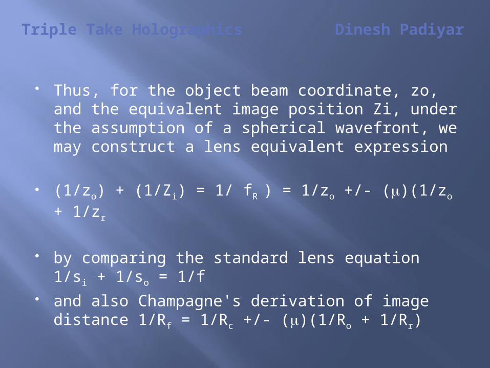
Thus, for the object beam coordinate, zo, and the equivalent image position Zi, under the assumption of a spherical wavefront, we may construct a lens equivalent expression
(1/zo) + (1/Zi) = 1/ fR ) = 1/zo +/- ()(1/zo + 1/zr
by comparing the standard lens equation 1/si + 1/so = 1/f
and also Champagne's derivation of image distance 1/Rf = 1/Rc +/- ()(1/Ro + 1/Rr)

Triple Take Holographics Dinesh Padiyar
ResolutionNot valid to compare with electronic pixels.Strictly, the resolution of the image as a
function of source size needs to be calculated using the Van Cittert-Zernike theorem
May be described as a comparison of the size of the reconstruction point to the size of the image source, giving:
dXi/d xc = (zozr)/(zozr + ( zozr – zozc))
dZi/d zc = (zozr)/(zozr + (zczr – zczo))
Triple Take Holographics Dinesh Padiyar
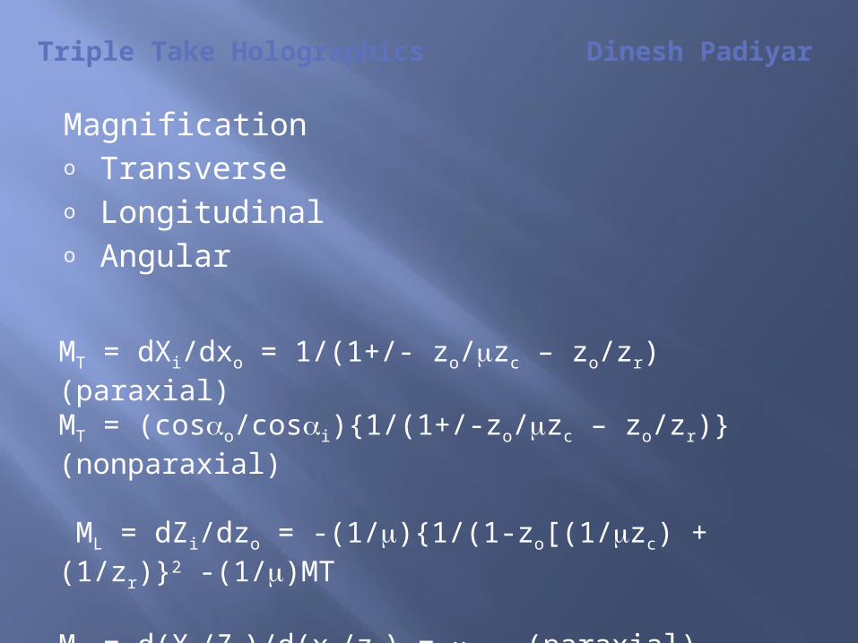
Magnificationo Transverseo Longitudinalo Angular
MT = dXi/dxo = 1/(1+/- zo/zc – zo/zr) (paraxial)MT = (coso/cosi){1/(1+/-zo/zc – zo/zr)} (nonparaxial)
ML = dZi/dzo = -(1/){1/(1-zo[(1/zc) + (1/zr)}2 -(1/)MT MA = d(Xi/Zi)/d(xo/zo) = (paraxial)MA = coso/cosi) (nonparaxial)
Triple Take Holographics Dinesh Padiyar
Expanding the spherical wavefront expression to third order produces the third order aberrations – the Seidel Aberrations for holography.
Once again, the difference between the ideal sphere and the actual wavefront, W, gives the actual aberratiion function.
Triple Take Holographics Dinesh Padiyar
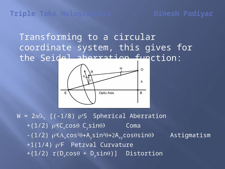
W = 2c [(-1/8)S Spherical Aberration
+(1/2)CxcosCysin Coma
-(1/2)xcos2Aysin2Axycossin) Astigmatism
+1(1/4)F Petzval Curvature+(1/2) r(Dxcos+ Dysin)] Distortion
Transforming to a circular coordinate system, this gives for the Seidel aberration function:
Triple Take Holographics Dinesh Padiyar
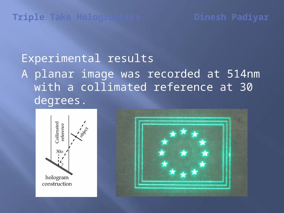
Experimental resultsA planar image was recorded at 514nm with
a collimated reference at 30 degrees.

Triple Take Holographics Dinesh Padiyar
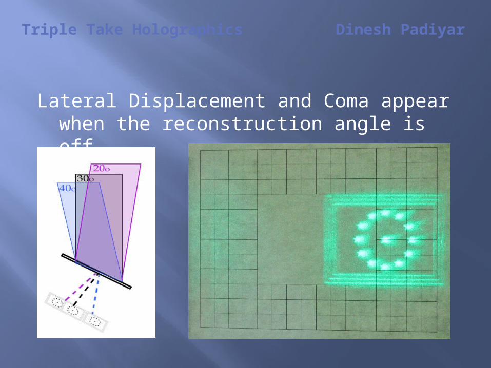
This was reconstructed under a variety of alternate beam geometries:
o Varying reconstruction angle + /-o Varying beam divergence + / -o Alternate wavelength at those geometries
We shall see how these changes affect the image by imaging onto a screen with a calibrated scale.
Triple Take Holographics Dinesh Padiyar
Lateral Displacement and Coma appear when the reconstruction angle is off.
Triple Take Holographics Dinesh Padiyar
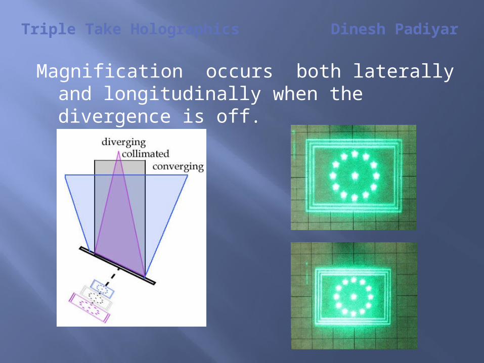
Magnification occurs both laterally and longitudinally when the divergence is off.
Triple Take Holographics Dinesh Padiyar
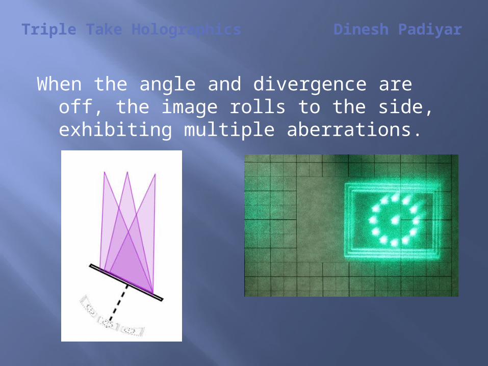
When the angle and divergence are off, the image rolls to the side, exhibiting multiple aberrations.
Triple Take Holographics Dinesh Padiyar
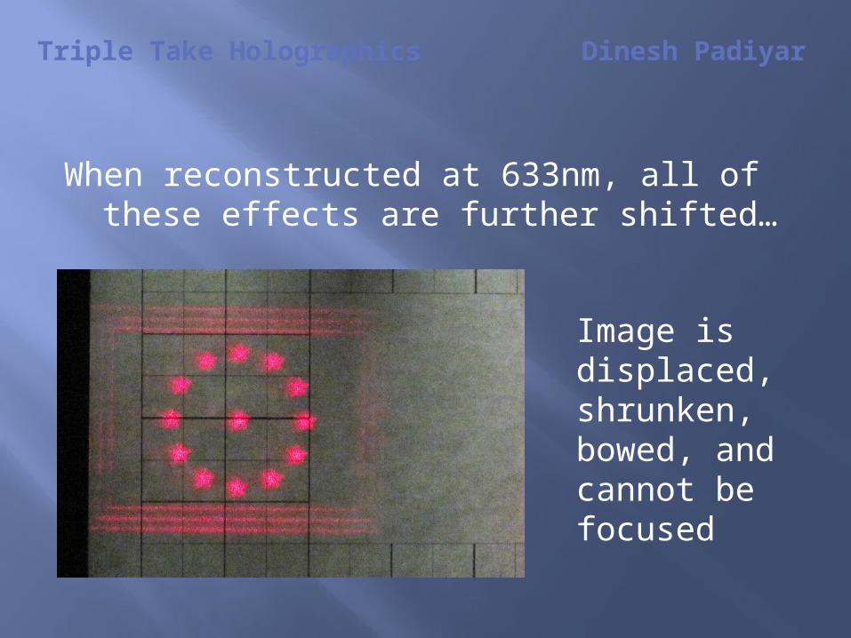
When reconstructed at 633nm, all of these effects are further shifted…
Image is displaced,shrunken,bowed, andcannot be focused

Triple Take Holographics Dinesh Padiyar
Conclusion:
Best practice is to always reconstruct a hologram with a source that matches the construction geometry, including avoiding aberrations occurring within the reconstruction source itself.
When aberrations occur, understanding the different effects will aid in troubleshooting the system.
Triple Take Holographics
Dinesh Padiyar
Thank You