abjac 111 user guide
DESCRIPTION
user guideTRANSCRIPT

Aspen B-JAC 11.1
User Guidefor Windows®

Version Number: 11.1September 2001
Copyright (c) 2001 by Aspen Technology, Inc. All rights reserved.
AspenTech®, Aspen Engineering Suite, Aspen Plus®, Aspen Properties, Aspen B-JAC, B-JAC®, AspenHetran, Aerotran®, Aspen Aerotran, Aspen Teams, Teams®, the aspen leaf logo and Plantelligence aretrademarks or registered trademarks of Aspen Technology, Inc., Cambridge, MA.
All other brand and product names are trademarks or registered trademarks of their respective companies.
This manual is intended as a guide to using AspenTech's software. This documentation contains AspenTechproprietary and confidential information and may not be disclosed, used, or copied without the prior consent ofAspenTech or as set forth in the applicable license agreement. Users are solely responsible for the proper use of thesoftware and the application of the results obtained.
Although AspenTech has tested the software and reviewed the documentation, the sole warranty for the softwaremay be found in the applicable license agreement between AspenTech and the user. ASPENTECH MAKES NOWARRANTY OR REPRESENTATION, EITHER EXPRESSED OR IMPLIED, WITH RESPECT TO THISDOCUMENTATION, ITS QUALITY, PERFORMANCE, MERCHANTABILITY, OR FITNESS FOR APARTICULAR PURPOSE.
CorporateAspen Technology, Inc.Ten Canal ParkCambridge, MA 02141-2201USAPhone: (617) 949-1000Fax: (617) 949-1030Website:http://www.aspentech.com
DivisionDesign, Simulation and Optimization SystemsAspen Technology, Inc.Ten Canal ParkCambridge, MA 02141-2201USAPhone: (617) 949-1000Fax: (617) 949-1030

Aspen B-JAC 111 User Guide Contents •••• iii
Contents
1 Introduction......................................................................................................1-1Related Documentation ....................................................................................................1-1Technical Support ............................................................................................................1-2
Online Technical Support Center.........................................................................1-2Contacting Customer Support ..............................................................................1-2
2 The User Interface ...........................................................................................2-1Aspen B-JAC Programs ...................................................................................................2-1Aspen Plus Integration .....................................................................................................2-2Aspen Pinch Integration ...................................................................................................2-2Aspen Zyqad Integration..................................................................................................2-3Installation Notes..............................................................................................................2-3
Version Control Utility (BJACVC.exe) ...............................................................2-3User Customized Database Files..........................................................................2-4
Accessing Aspen B-JAC Program Files...........................................................................2-5Data Maintenance.............................................................................................................2-5
Units of Measure ..................................................................................................2-5Heat Exchanger Standards ...................................................................................2-5Chemical Databank (B-JAC Props & Priprops)...................................................2-5Materials Databank (B-JAC Databank & Primetals) ...........................................2-6Materials Defaults (Defmats) ...............................................................................2-6Costing (Newcost Database) ................................................................................2-6Frequently Used Materials and Chemical Components.......................................2-6Program Settings ..................................................................................................2-7
General Program Operation .............................................................................................2-8Operating Procedure.............................................................................................2-8
The Aspen B-JAC Program Window...............................................................................2-9Title Bar................................................................................................................2-9Screen Control Buttons ........................................................................................2-9Menu Bar............................................................................................................2-10File Menu ...........................................................................................................2-10Edit Menu...........................................................................................................2-10Run Menu...........................................................................................................2-11Tools Menu ........................................................................................................2-11View Menu.........................................................................................................2-11Window Menu....................................................................................................2-12Help Menu..........................................................................................................2-12

iv •••• Contents Aspen B-JAC 111
Toolbar ...............................................................................................................2-13Toolbar Buttons..................................................................................................2-13Toolbar ...............................................................................................................2-14Next ....................................................................................................................2-14Units Box ...........................................................................................................2-15Zoom In/Zoom Out ............................................................................................2-15Navigator Tree, Forms and Sheets .....................................................................2-15Prompt Area .......................................................................................................2-15Status Bar ...........................................................................................................2-16
Program Input.................................................................................................................2-16Key Functions ....................................................................................................2-16Input Fields.........................................................................................................2-17Units of Measure – Field Specific......................................................................2-18Databank Reference ...........................................................................................2-19Range Checks.....................................................................................................2-20Change Codes.....................................................................................................2-20The Database Concept........................................................................................2-20
Program Output ..............................................................................................................2-21Display Output ...................................................................................................2-21Printed Output ....................................................................................................2-21Drawings ............................................................................................................2-21
Help Facility...................................................................................................................2-22General Help ......................................................................................................2-22Field Specific General Help Topic.....................................................................2-22Field Specific "What's This?" Help....................................................................2-22Importing/Exporting Design Data Information to Other OLE CompliantApplications .......................................................................................................2-22
Filenames & Filetypes....................................................................................................2-23Filenames ...........................................................................................................2-23Filetypes .............................................................................................................2-23
3 Aspen Hetran ...................................................................................................3-1Introduction ......................................................................................................................3-1
Thermal Scope......................................................................................................3-2Mechanical Scope ................................................................................................3-3
Input .................................................................................................................................3-7Problem Definition...............................................................................................3-7Description ...........................................................................................................3-7Application Options .............................................................................................3-8Process Data .......................................................................................................3-10
Physical Property Data ...................................................................................................3-13Property Options ................................................................................................3-13Hot Side Composition ........................................................................................3-17Hot Side Properties.............................................................................................3-20

Aspen B-JAC 111 User Guide Contents •••• v
Cold Side Composition ......................................................................................3-23Component Properties Cold Side .......................................................................3-24Cold Side Properties...........................................................................................3-25
Exchanger Geometry......................................................................................................3-28Exchanger Type..................................................................................................3-28Tubes ..................................................................................................................3-36Bundle ................................................................................................................3-42Layout Limits .....................................................................................................3-49Clearances ..........................................................................................................3-49Baffles ................................................................................................................3-50Rating/Simulation Data ......................................................................................3-55Nozzles ...............................................................................................................3-59
Design Data ....................................................................................................................3-62Design Constraints .............................................................................................3-62Materials.............................................................................................................3-67Specifications .....................................................................................................3-69
Program Options ............................................................................................................3-72Thermal Analysis ...............................................................................................3-72Correlations ........................................................................................................3-75Change Codes.....................................................................................................3-77
Results ............................................................................................................................3-81Design Summary................................................................................................3-81
Thermal Summary..........................................................................................................3-86Performance .......................................................................................................3-86Coefficients & MTD ..........................................................................................3-87Pressure Drop .....................................................................................................3-88TEMA Sheet.......................................................................................................3-92
Mechanical Summary.....................................................................................................3-93Exchanger Dimensions.......................................................................................3-93Vibration & Resonance Analysis .......................................................................3-95Setting Plan & Tubesheet Layout.......................................................................3-98
Calculation Details .......................................................................................................3-100Interval Analysis – Shell Side & Tube Side.....................................................3-100VLE – Hot Side ................................................................................................3-102VLE – Cold Side ..............................................................................................3-102Maximum Rating..............................................................................................3-103Property Temperature Limits ...........................................................................3-103
Hetran-Design Methods ...............................................................................................3-104Optimization Logic ..........................................................................................3-104No Phase Change .............................................................................................3-109Simple Condensation .......................................................................................3-109Complex Condensation ....................................................................................3-111Simple Vaporization.........................................................................................3-113Complex Vaporization .....................................................................................3-115Falling Film Evaporators..................................................................................3-116

vi •••• Contents Aspen B-JAC 111
4 Aspen Aerotran................................................................................................4-1Introduction ......................................................................................................................4-1
Thermal Scope......................................................................................................4-2Mechanical Scope ................................................................................................4-2
Input .................................................................................................................................4-5Problem Definition...............................................................................................4-5Description ...........................................................................................................4-5Application Options .............................................................................................4-6Process Data .........................................................................................................4-8
Physical Property Data ...................................................................................................4-12Property Options ................................................................................................4-12Tube Side Composition......................................................................................4-16Tube Side Properties ..........................................................................................4-19Outside Tubes Composition...............................................................................4-21Outside Tubes Properties ...................................................................................4-22Exchanger Geometry..........................................................................................4-24Rating/Simulation Data ......................................................................................4-28Headers & Nozzles.............................................................................................4-30Construction Options .........................................................................................4-32
Design Data ....................................................................................................................4-34Design Constraints .............................................................................................4-34
Materials - Vessel Components......................................................................................4-38Specifications .................................................................................................................4-39Program Options ............................................................................................................4-42
Thermal Analysis ...............................................................................................4-42Change Codes.....................................................................................................4-46
Results ............................................................................................................................4-49Recap of Designs................................................................................................4-53Warnings & Messages........................................................................................4-53
Thermal Summary..........................................................................................................4-54Performance .......................................................................................................4-54Coefficients & MTD ..........................................................................................4-55Pressure Drop .....................................................................................................4-56API Sheet............................................................................................................4-58
Mechanical Summary.....................................................................................................4-59Exchanger Dimensions.......................................................................................4-59Setting Plan & Tubesheet Layout.......................................................................4-60
Calculation Details .........................................................................................................4-62Interval Analysis – Tube Side ............................................................................4-62
Aerotran Design Methods ..............................................................................................4-65Optimization Logic ............................................................................................4-65No Phase Change ...............................................................................................4-67Simple Condensation .........................................................................................4-68Complex Condensation ......................................................................................4-68Simple Vaporization...........................................................................................4-70

Aspen B-JAC 111 User Guide Contents •••• vii
5 Aspen Teams ...................................................................................................5-1Introduction ......................................................................................................................5-1
Organization of Input Information .......................................................................5-2Teams Run Options..............................................................................................5-3Navigator Contents...............................................................................................5-3Teams Scope ........................................................................................................5-6Output...................................................................................................................5-7Drawings ..............................................................................................................5-8
Input .................................................................................................................................5-9Problem Definition...............................................................................................5-9Description ...........................................................................................................5-9Application Options ...........................................................................................5-10Design Specifications.........................................................................................5-11Exchanger Geometry..........................................................................................5-12Front Head..........................................................................................................5-13Shell....................................................................................................................5-17Rear Head...........................................................................................................5-19Shell Cover.........................................................................................................5-22Flanges ...............................................................................................................5-23Tubesheet ...........................................................................................................5-29Expansion Joints.................................................................................................5-35Expansion Joint Geometry .................................................................................5-37Tubes/Baffles .....................................................................................................5-38Fin Tube Data.....................................................................................................5-40Tubesheet Layout ...............................................................................................5-44Nozzles General .................................................................................................5-48Nozzle Details ....................................................................................................5-50Horizontal Supports ...........................................................................................5-52Vertical Supports................................................................................................5-54Lift Lugs.............................................................................................................5-56
Materials.........................................................................................................................5-57Main Materials ...................................................................................................5-57Nozzle Materials ................................................................................................5-58
Program Options ............................................................................................................5-59Wind/Seismic/External Loads............................................................................5-59Change Codes.....................................................................................................5-59Change Codes - Cylinders & Covers .................................................................5-62Change Codes - Nozzles ....................................................................................5-63Change Codes – Body Flanges...........................................................................5-64Change Codes - Floating Head Flange...............................................................5-65Change Codes - Tubesheets & Expansion Joint ................................................5-66Change Codes - Supports ...................................................................................5-67Change Codes - Dimensions ..............................................................................5-67

viii •••• Contents Aspen B-JAC 111
Results ............................................................................................................................5-68Input Summary...................................................................................................5-68Design Summary................................................................................................5-69Design Specifications/Materials.........................................................................5-70Overall Dimensions/Fitting Locations ...............................................................5-72MDMT/MAWP/Test Pressure ...........................................................................5-73Vessel Dimensions .............................................................................................5-74Cylinders & Covers............................................................................................5-75Nozzles/Nozzle Flanges .....................................................................................5-76Flanges ...............................................................................................................5-77Tubesheets/Tube Details ....................................................................................5-77Supports / Lift Lugs / Wind & Seismic Loads ...................................................5-78
Price................................................................................................................................5-79Cost Estimate .....................................................................................................5-79Bill of Materials .................................................................................................5-79Labor Details ......................................................................................................5-79
Drawings ........................................................................................................................5-80Setting Plan Drawing .........................................................................................5-80Tubesheet Layout : Tube Layout Drawing ........................................................5-81All Drawings: Fabrication Drawings .................................................................5-82Code Calculations ..............................................................................................5-82
6 Props.................................................................................................................6-1Introduction ......................................................................................................................6-1Props Scope......................................................................................................................6-2
Physical Properties ...............................................................................................6-2Input .................................................................................................................................6-4
Application Options .............................................................................................6-4Property Options ..................................................................................................6-5
Composition .....................................................................................................................6-9Composition .........................................................................................................6-9
Results ............................................................................................................................6-15Warnings & Messages........................................................................................6-15VLE ....................................................................................................................6-18Props Logic ........................................................................................................6-19References ..........................................................................................................6-22
Databank Symbols..........................................................................................................6-23
7 Priprops............................................................................................................7-1Introduction ......................................................................................................................7-1Accessing the Priprops databank......................................................................................7-1
Accessing an existing component in the databank...............................................7-1Adding a new component to Priprops ..................................................................7-2Adding a new component using an existing component as a template:...............7-2
Property Reference...........................................................................................................7-2

Aspen B-JAC 111 User Guide Contents •••• ix
Property Estimation..........................................................................................................7-3Property Curves....................................................................................................7-3Property estimation based on NBP.......................................................................7-3
8 Qchex................................................................................................................8-1Introduction ......................................................................................................................8-1
Mechanical Scope ................................................................................................8-2Input .................................................................................................................................8-4
Problem Definition...............................................................................................8-4Description ...........................................................................................................8-4Exchanger Geometry............................................................................................8-5Shell type..............................................................................................................8-6Tube to tubesheet joint .........................................................................................8-9Exchanger Data ..................................................................................................8-10Design Data ........................................................................................................8-18Qchex - Program Operation ...............................................................................8-19
Qchex - Results ..............................................................................................................8-20Input Summary...................................................................................................8-20Warnings & Messages........................................................................................8-20Design Summary................................................................................................8-21Cost Summary....................................................................................................8-21
Qchex Logic ...................................................................................................................8-21Qchex References...............................................................................................8-26
9 Ensea ................................................................................................................9-1Introduction ......................................................................................................................9-1
Mechanical Scope ................................................................................................9-2Input .................................................................................................................................9-4
Problem Definition...............................................................................................9-4Application Options .............................................................................................9-4
Exchanger Geometry........................................................................................................9-7Exchanger.............................................................................................................9-7Tubes & Baffles .................................................................................................9-10Tube Layout .......................................................................................................9-13Tube Row Details...............................................................................................9-18Program Operation .............................................................................................9-18Results ................................................................................................................9-19Input Data...........................................................................................................9-19Warnings & Messages........................................................................................9-19
Summary & Details ........................................................................................................9-20Summary ............................................................................................................9-20Tube Row Details...............................................................................................9-20U-bend Details....................................................................................................9-21Tubesheet Layout ...............................................................................................9-22Ensea - Logic......................................................................................................9-23Ensea References................................................................................................9-24

x •••• Contents Aspen B-JAC 111
10 Metals..............................................................................................................10-1Introduction ....................................................................................................................10-1
Metals Scope ......................................................................................................10-2Input ...................................................................................................................10-3Program Operation .............................................................................................10-4
Results ............................................................................................................................10-5Warnings & Messages........................................................................................10-5
References ......................................................................................................................10-8Metals Directory - ASTM - Generic ..................................................................10-9Metals Directory - ASTM - Pipe......................................................................10-10Low Alloy Pipe and Weld Cap ........................................................................10-10Metals Directory - ASTM - Plate.....................................................................10-13Metals Directory - ASTM - Bolting.................................................................10-17Metals Directory - ASTM - Forging ................................................................10-19Metals Directory - ASTM - Coupling ..............................................................10-20Metals Directory - ASTM - Gasket..................................................................10-22Metals Directory - ASTM - Tube.....................................................................10-24Metals Directory - AFNOR - Genenic .............................................................10-27Metals Directory - AFNOR - Pipe ...................................................................10-28Metals Directory - AFNOR - Plate ..................................................................10-29Metals Directory - AFNOR - Bolting ..............................................................10-31Metals - Directory - AFNOR - Forging ...........................................................10-31Metals Directory - AFNOR - Gasket ...............................................................10-33Metals Directory - AFNOR - Tube ..................................................................10-34Metals Directory - DIN - Generic ....................................................................10-35Metals Directory - DIN - Pipe..........................................................................10-36Metals Directory - DIN - Plate.........................................................................10-38Metals Directory - DIN - Bolting.....................................................................10-40Metals Directory - DIN - Forging ....................................................................10-41Metals - Directory - DIN - Gasket ...................................................................10-43Metals Directory - DIN - Tube.........................................................................10-44
11 Primetals.........................................................................................................11-1Introduction ....................................................................................................................11-1Example Input to Primetals ............................................................................................11-5
12 Newcost Database .........................................................................................12-1Introduction ....................................................................................................................12-1
Labor & Cost Standards .....................................................................................12-2
13 B-JAC Example Run ......................................................................................13-1Aspen B-JAC Example ..................................................................................................13-1

Aspen B-JAC 111 User Guide Contents •••• xi
14 Exporting Results from B-JAC to Excel.......................................................14-1Introduction ....................................................................................................................14-1
Export features -- B-JAC Templates..................................................................14-1Creating your own customized Template...........................................................14-2Copying Data from a B-JAC application to Excel.............................................14-3Example of Pasting Aspen B-JAC results into Excel. .......................................14-4Launching B-JAC programs from Excel............................................................14-5
15 Using the ASPEN B-JAC ActiveX Automation Server ................................15-1Introduction ....................................................................................................................15-1
About the Automation Server ............................................................................15-2Using the Automation Server.............................................................................15-2Viewing the ASPEN B-JAC Objects .................................................................15-4Overview of the ASPEN B-JAC Objects...........................................................15-5Programming with ASPEN B-JAC Objects.....................................................15-11
Reference Information..................................................................................................15-21

xii •••• Contents Aspen B-JAC 111

Aspen B-JAC 11.1 User Guide 1-1
1 Introduction
The purpose of this User Guide is to provide a quick overview of the Aspen B-JAC
programs, supported operating systems, equipment requirements, program installationinstructions, and a summary of the basic program operation. The Aspen B-JAC programshave been designed around the same basic user interface. Once a user is familiar with theoperation of one program, that knowledge can easily be transferred to another Aspen B-JACprogram.
This User Guide outlines the concepts of program input, program operation, and programoutput used throughout all the Aspen B-JAC programs. For detailed instructions orinformation on specific programs, you should refer to the appropriate section in this manual.
Much of information in the User Guide is also available through the Help facility in theAspen B-JAC software.
Related DocumentationIn addition to this document, a number of other documents are provided to help users learnand use Aspen B-JAC products. All manuals are available in PDF format.
Installation Manuals
Aspen Engineering Suite 11.1 Installation Manual
Aspen Plus
Aspen Plus Getting Started GuidesAspen Plus User GuideAspen Plus Reference ManualsAspen Physical Property System Reference Manuals

1-2 Aspen B-JAC 11.1 User Guide
Aspen Pinch
Aspen Pinch User Guide
Technical Support
Online Technical Support CenterAspenTech customers with a valid license and software maintenance agreement can registerto access the Online Technical Support Center at:
http://support.aspentech.com
This web support site allows you to:• Access current product documentation• Search for tech tips, solutions and frequently asked questions (FAQs)• Search for and download application examples• Search for and download service packs and product updates• Submit and track technical issues• Search for and review known limitations• Send suggestions
Registered users can also subscribe to our Technical Supporte-Bulletins. These e-Bulletins are used to proactively alert users to important technicalsupport information such as:• Technical advisories• Product updates• Service Pack announcements• Product release announcements
Contacting Customer SupportCustomer support is also available by phone, fax, and email for customers with a currentsupport contract for this product. For the most up-to-date phone listings, please see the OnlineTechnical Support Center at:
http://support.aspentech.com

Aspen B-JAC 11.1 User Guide 1-3
Hours
Support Centers Operating Hours
North America 8:00 – 20:00 Eastern TimeSouth America 9:00 – 17:00 Local timeEurope 8:30 – 18:00 Central European timeAsia and Pacific Region 9:00 – 17:30 Local time
Phone
Support Centers Phone Numbers
1-888-996-7100 toll-free from U.S., Canada,Mexico
1-281-584-4357 North America Support Center
North America
(52) (5) 536-2809 Mexico Support Center(54) (11) 4361-7220 Argentina Support Center(55) (11) 5012-0321 Brazil Support Center(0800) 333-0125 Toll-free to U.S. from Argentina(000) (814) 550-4084 Toll-free to U.S. from Brazil
South America
8001-2410 Toll-free to U.S. from Venezuela(32) (2) 701-95-55 European Support CenterCountry specific toll-free numbers:Belgium (0800) 40-687Denmark 8088-3652Finland (0) (800) 1-19127France (0805) 11-0054Ireland (1) (800) 930-024Netherlands (0800) 023-2511Norway (800) 13817Spain (900) 951846Sweden (0200) 895-284Switzerland (0800) 111-470
Europe
UK (0800) 376-7903(65) 395-39-00 SingaporeAsia and Pacific Region(81) (3) 3262-1743 Tokyo

1-4 Aspen B-JAC 11.1 User Guide
Fax
Support Centers Fax Numbers
North America 1-617-949-1724 (Cambridge, MA)1-281-584-1807 (Houston, TX: both Engineering andManufacturing Suite)1-281-584-5442 (Houston, TX: eSupply Chain Suite)1-281-584-4329 (Houston, TX: Advanced Control Suite)1-301-424-4647 (Rockville, MD)1-908-516-9550 (New Providence, NJ)1-425-492-2388 (Seattle, WA)
South America (54) (11) 4361-7220 (Argentina)(55) (11) 5012-4442 (Brazil)
Europe (32) (2) 701-94-45Asia and Pacific Region (65) 395-39-50 (Singapore)
(81) (3) 3262-1744 (Tokyo)
Support Centers E-mail
North America [email protected] (Engineering Suite)[email protected] (Aspen ICARUS products)[email protected] (Aspen MIMI products)[email protected] (Aspen PIMS products)[email protected] (Aspen Retail products)[email protected](Advanced Control products)[email protected] (Manufacturing Suite)[email protected] (Mexico)
South America [email protected] (Argentina)[email protected] (Brazil)
Europe [email protected] (Engineering Suite)[email protected] (All other suites)[email protected] (CIMVIEW products)
Asia and Pacific Region [email protected] (Singapore: Engineering Suite)[email protected] (Singapore: All other suites)[email protected] (Tokyo: Engineering Suite)[email protected] (Tokyo: All other suites)
❖ ❖ ❖ ❖

Aspen B-JAC 11.1 User Guide 2-1
2 The User Interface
Aspen B-JAC ProgramsThe Aspen B-JAC software includes a number of programs for the thermal design,mechanical design, cost estimation, and drawings for heat exchangers and pressure vessels.
The major design programs are:Aspen Hetran Thermal Design of Shell & Tube Heat Exchangers
Aspen Teams Mechanical Design, Cost Estimation, and DesignDrawings of Shell &Tube Heat Exchangers andPressure Vessels
Aspen Aerotran Thermal Design of Air Cooled Heat Exchangers,Flue Gas Heat Recuperators, and Fired HeaterConvection Sections
In addition to the major design programs, there are a number of programs which support thedesign programs. These are:
Props Chemical Physical Properties Databank
Priprops Program to Build a Private Databank for Props
Metals Metal Properties Databank
Primetals Program to Build a Private Databank for Metals
Ensea Tubesheet Layout Program
Qchex Budget Cost Estimation Program
Draw Graphics Interface Program for Drawings
Newcost Program for Maintaining Labor & MaterialDatabases
Defmats Program for Establishing Default Materials

2-2 Aspen B-JAC 11.1 User Guide
Aspen Plus IntegrationThe Aspen B-JAC Hetran and Aerotran programs are completely integrated with the AspenPlus process simulation software. Users with licenses for both the Aspen B-JAC thermalanalysis software and the Aspen Plus simulation software can utilize the Aspen B-JACthermal models for shell and tube heat exchangers and air-cooled heat exchangers within theAspen Plus flowsheet.
The models can be accessed from Aspen Plus by selecting the blocks Hetran or Aerotran forthe heat transfer unit operations. Stream and property curve data for these blocks can besupplied to the Aspen B-JAC programs by Aspen Plus or from within the Aspen B-JAC inputfile which is referenced in the Aspen Plus input for the block. All exchanger geometry datamust be specified through the Aspen B-JAC input file.
During simulation the Aspen Plus simulator will repetitively call the Aspen B-JAC analysisprograms to predict the outlet conditions of the heat transfer equipment. The results of theanalysis are returned to Aspen Plus which then feeds them to subsequent blocks. A subset ofthe exchanger performance can be viewed from within the Aspen Plus environment or alldetailed results of the block can be viewed through the Aspen B-JAC user interface.
Aspen Pinch IntegrationThe Aspen B-JAC Hetran program is completely integrated with the Aspen Pinch processsynthesis software. Users with licenses for both the Aspen B-JAC thermal analysis softwareand the Aspen Pinch software can utilize the Aspen B-JAC thermal models for shell and tubeheat exchangers within the Aspen Pinch flowsheet.
The models can be accessed from Aspen Plus by selecting the block Hetran for the heattransfer unit operations. Stream and property curve data for these blocks can be supplied tothe Aspen B-JAC programs by Aspen Pinch or from within the Aspen B-JAC input file whichis referenced in the Aspen Pinch input for the block. All exchanger geometry data must bespecified through the Aspen B-JAC input file.
During simulation the Aspen Pinch simulator will repetitively call the Aspen B-JAC analysisprograms to predict the outlet conditions of the heat transfer equipment. The results of theanalysis are returned to Aspen Pinch which then feeds them to subsequent blocks. A subset ofthe exchanger performance can be viewed from within the Aspen Pinch environment or alldetailed results of the block can be viewed through the Aspen B-JAC user interface.

Aspen B-JAC 11.1 User Guide 2-3
Aspen Zyqad IntegrationThe Aspen B-JAC Hetran program is completely integrated with the Aspen Aspen Zyqad.Aspen Zyqad is an engineering database tool used to capture process knowledge about thedesign, construction, or operation of a process plant. The database contains a number of datamodels to store information about the process streams, the process configuration, and theindividual pieces of process equipment. The user can retrieve the information & generate anynumber of specialized reports & equipment specification sheets from the data in the database.
Installation Notes
Version Control Utility (BJACVC.exe)
The Version Control Utility, BJACVC.exe located in the B-JAC 11.*\XEQ folder, will allowyou to switch between B-JAC program versions. To execute the BJACVC.exe utility, locate thefile using Explorer and double click on it with the mouse cursor.
Selecting a B-JAC program version: Select which version you wish to run and the utility willupdate the MS Windows registry to allow you to run the selected B-JAC program version. TheBJACVC.exe will automatically execute when you open a B-JAC program version that is notregistered properly.
Copying customized files: Select the source version where your existing customized databasefiles are located. Next select the target new version where you wish to copy the database filesto. Next select what files you wish to transfer and then select Copy to copy the customized filesto the new version.
Copying program settings: To copy the program settings from an existing B-JAC version to anew version, first select the source version. Next select the target new program version. Nowselect Apply and the program settings will be copied to the new targeted version.
2-4 Aspen B-JAC 11.1 User Guide
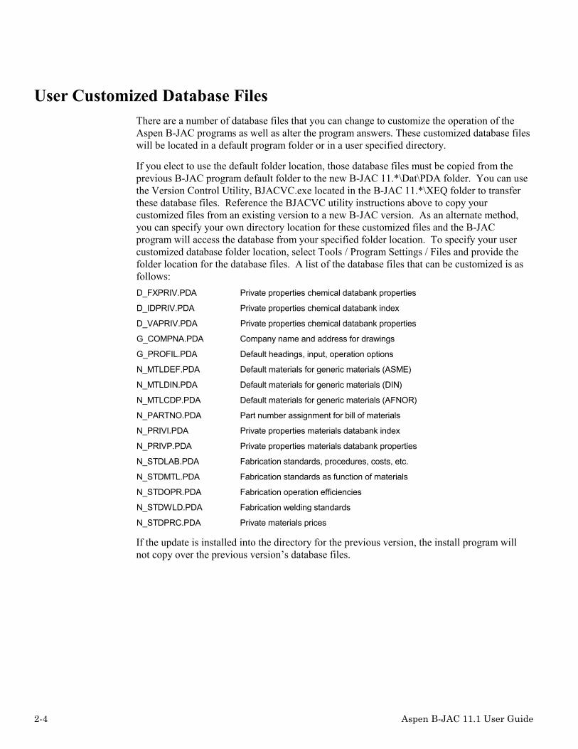
User Customized Database FilesThere are a number of database files that you can change to customize the operation of theAspen B-JAC programs as well as alter the program answers. These customized database fileswill be located in a default program folder or in a user specified directory.
If you elect to use the default folder location, those database files must be copied from theprevious B-JAC program default folder to the new B-JAC 11.*\Dat\PDA folder. You can usethe Version Control Utility, BJACVC.exe located in the B-JAC 11.*\XEQ folder to transferthese database files. Reference the BJACVC utility instructions above to copy yourcustomized files from an existing version to a new B-JAC version. As an alternate method,you can specify your own directory location for these customized files and the B-JACprogram will access the database from your specified folder location. To specify your usercustomized database folder location, select Tools / Program Settings / Files and provide thefolder location for the database files. A list of the database files that can be customized is asfollows:D_FXPRIV.PDA Private properties chemical databank properties
D_IDPRIV.PDA Private properties chemical databank index
D_VAPRIV.PDA Private properties chemical databank properties
G_COMPNA.PDA Company name and address for drawings
G_PROFIL.PDA Default headings, input, operation options
N_MTLDEF.PDA Default materials for generic materials (ASME)
N_MTLDIN.PDA Default materials for generic materials (DIN)
N_MTLCDP.PDA Default materials for generic materials (AFNOR)
N_PARTNO.PDA Part number assignment for bill of materials
N_PRIVI.PDA Private properties materials databank index
N_PRIVP.PDA Private properties materials databank properties
N_STDLAB.PDA Fabrication standards, procedures, costs, etc.
N_STDMTL.PDA Fabrication standards as function of materials
N_STDOPR.PDA Fabrication operation efficiencies
N_STDWLD.PDA Fabrication welding standards
N_STDPRC.PDA Private materials prices
If the update is installed into the directory for the previous version, the install program willnot copy over the previous version’s database files.

Aspen B-JAC 11.1 User Guide 2-5
Accessing Aspen B-JAC Program FilesMost users will want their input and output files stored on a directory separate from theAspen B-JAC programs. The input and output files are read from or written to the currentdirectory on your PC. This allows you to organize your input and output files however youwish. We recommend that you run from a directory other than the directory in which theAspen B-JAC programs are installed.
Data Maintenance
Units of MeasureYou can access the Units of Measure by selecting Tools in the Menu Bar and then selectingthe Data Maintenance section. You can set the default units of measure to US, SI, or Metricand also set up your own customized set of units. In the Units Maintenance section you cancustomize the conversion factors used and the number of decimal point shown in the results.
Heat Exchanger StandardsThis function allows you to create a database with your standard exchangers sizes that canreference from the B-JAC design programs.
Chemical Databank (B-JAC Props & Priprops)This item provides access to the Aspen B-JAC Props, chemical databank, and Priprops, theuser private property databases. The Priprops program allows you to build your own privateproperty databank that can be accessed form the Hetran, Aerotran, and Props programs.Reference the Priprops section of this manual for additional information.

2-6 Aspen B-JAC 11.1 User Guide
Materials Databank (B-JAC Databank & Primetals)This item provides access to the Aspen B-JAC Metals, material databank, and Primetals, theprivate property metals databases. The Primetals program allows you to build your ownprivate property databank that can be accessed from the Hetran, Aerotran, and Teamsprograms. Reference the Primetals section of this manual for additional information.
Materials Defaults (Defmats)This item provides access to the B-JAC Defmats, material defaults database for metals in thedatabanks. The Defmats program allows you to change the specified material specifications tobe used when the generic material references are specified.
Costing (Newcost Database)This item provides access to the Newcost fabrication standards and material pricingdatabases. Labor, fabrication standards, and material pricing may be customized yourapplications. For more information, see the Newcost Database section of this manual.
Frequently Used Materials and Chemical ComponentsYou can set a list of frequently used materials and/or chemical components for the databanksearch engines. This will allow to search for a material or component from your personalizedlist of items you use often.

Aspen B-JAC 11.1 User Guide 2-7
Program SettingsFile Save Options: Set the auto-save file functions. You can set the program to save yourfile information every few minutes or at the time the program is executed.
Company Logo: By providing the reference to a Bitmap file, you can add your company logoto the program results and drawings.
Default Units of Measure: You can set the default units of measure to US, SI, or Metric.Note that the units may be changed at any time in the Aspen B-JAC program window.
Headings/Drawing Title: You can set up the default headings and title block informationthat will appear on the printed output and drawings.
Nozzle size specification on drawings: You can set the units set basis for the nozzle sizesshown on the drawings. For example, US unit size nozzles can be shown even though thedrawings are in SI or metric units.
Folder for customized database files: You can specify a folder location for your customizeddatabase files. The B-JAC programs will then reference your customized database files in thespecified folder in lieu of the standard database files in the program PDA folder.
Excel templates: Specify the Excel template file you wish to use for each program as adefault. When the File / Export / Excel feature is selected, the specified default template willthen be used.
Heat exchanger standards: Set which exchanger standards database file is to be referenced.
Advanced: You can turn on variable attributes so they will be shown in the Aspen B-JACprogram prompt area. Set drag-drop format to move data to Excel. Set the maximum diskspace for temporary files.

2-8 Aspen B-JAC 11.1 User Guide
General Program Operation
Operating ProcedureMost of the Aspen B-JAC programs follow the same general operating procedures. These are:1. Enter the Aspen B-JAC program environment by clicking on the Aspen B-JAC icon or
select the Aspen B-JAC program from the Task Bar.
2. Select the appropriate Aspen B-JAC program by clicking on the New File icon orchoosing New under the File Menu. Check the box next to the desired program.
3. Enter the required data by accessing folders from the Navigation Tree and filling out therequired input forms with data.
4. Click on the Run icon in the Tool Bar or select the “Run Program” option under the Runcommand in the Menu Bar.
5. Review the Results section by accessing the results folders in the Navigation Tree.
6. If you want hardcopy results, choose Print from the File menu, check the boxes next tothe desired output, and click on “Print.”
7. If appropriate, make changes to the input data.
8. If making changes, then re-run the program.
9. Repeat steps 5 through 9 until you have the desired solution.
10. Update the file with current geometry by selecting the Run command from the Menu Barand then Update.
11. To transfer design information to other programs, select the Run command from theMenu Bar and then Transfer.
12. Leave the program by selecting Exit from the File menu. The program will ask if youwish to save changes. Click the appropriate button.
13. Save the input data at any time by clicking on Save under the File menu.

Aspen B-JAC 11.1 User Guide 2-9
The Aspen B-JAC Program Window
Title BarThe bar at the top of the window displays the current program and file name.
Screen Control ButtonsThe Minimize, Maximize and Restore keys change the size of the program window, andreturn the window to its original settings. The Close key closes the active program or file.

2-10 Aspen B-JAC 11.1 User Guide
Menu BarThe program has a number of additional features that can be accessed through a menu bar atthe top of each screen. Using the left mouse button, click on a menu name to see the pulldown options available. Click on a desired option or press the “Alt” key and the underscoredcharacter shown (some options can be accessed by a given “Ctrl” key + letter combination).
File MenuName Description
New (Ctrl+N) Opens new file for desired Aspen B-JAC program
Open (Ctrl+O) Opens existing Aspen B-JAC program file
Close Closes a chosen Aspen B-JAC program window
Add Application Opens a chosen Aspen B-JAC program window
Remove Application Removes a chosen Aspen B-JAC program window
Save (Ctrl+S) Saves current file under chosen filename
Save As Saves current file as a different filename
Export To Export results to Excel, a DXF file, a RTF file, or a DOC file
Print Setup Allows for change to printing options
Print (Ctrl+P) Prints desired results sections from Aspen B-JAC program
Description Displays the contents of the Description field in the input file
Exit Exits Aspen B-JAC program and return user to Windows
Edit MenuName Description
Undo Undoes the last edit operation.
Cut (Ctrl+X) Deletes the highlighted text.
Copy (Ctrl+C) Saves a copy of the highlighted text.
Paste (Ctrl+V) Paste inserts text from a copy to directed location

Aspen B-JAC 11.1 User Guide 2-11
Run MenuName Description
Run “Program” Runs a chosen Aspen B-JAC program
Stop Stops the run of a chosen Aspen B-JAC program
Transfer Transfers design information into another BJAC program
Update Updates file with final design information
Tools MenuName Description
Data Maintenance Provides access to units of measure, chemical database reference, materialdatabase, and Costing database.
Program Settings Default units setting and headings for drawings
Security Access to Aspen B-JAC security program.
Language Sets language to English, French, German, Spanish, Italian (Chinese andJapanese to be offered in a later version).
Plot Plots results functions.
Add Curve Allows the addition of another curve to an existing plotted curve
View MenuName Description
Tool Bar Shows or hides the Tool Bar
Status Bar Shows or hides the Status Bar
Zoom In Enlarges sections of the Aspen B-JAC drawings
Zoom Out Returns drawings to normal size
Refresh Refreshes screen
Variable List Displays variable list for form.

2-12 Aspen B-JAC 11.1 User Guide
Window MenuName Description
Cascade Arranges program windows one behind the other
Tile Horizontal Arranges program windows one on top another
Tile Vertical Arranges program windows one besides the other
Arrange Icons Automatically arranges icons
Create Creates a window for a Aspen B-JAC program
Help MenuName Description
Contents Open Aspen B-JAC help table of Contents
Search for Help Displays a list of topics for detailed help
About B-JAC Provides information on the current Aspen B-JAC release
What’s This Help Allows the user to place “?” on desired item to receive information about theitem

Aspen B-JAC 11.1 User Guide 2-13
Toolbar
Toolbar ButtonsName Description
New Creates a new Aspen B-JAC program file
Open Opens an existing Aspen B-JAC program file
Save Saves the current file data
Hetran Opens the Hetran program window
Teams Opens the Teams program window
Aerotran Opens the Aerotran program window
Props Opens the Props program window
Ensea Opens the Ensea tube layout window
Qchex Opens the Qchex budget costing window
Teamsc Opens the Teams Component design window
Metals Opens the Metals property database window
Run Runs the chosen Aspen B-JAC Program
Zoom In Enlarges sections of the Aspen B-JAC drawings
Zoom Our Returns sections of drawings to normal size
Plot Plot results functions
What’s This? Allows user to place “?” on desired item to receive information about the item

2-14 Aspen B-JAC 11.1 User Guide
Toolbar
Name Description
Navigator Allows quick access to forms in the Menu Tree
One Level Up Takes the user up one level in the Menu Tree
Hide Folder List Hides Navigator Menu Tree
Units Box Allow you to change globally the units of measure
Go Back Takes the user to the most recently viewed form
Go Forward Takes the user to the next form in the Menu Tree
Previous Form Takes the user to the previous form in the Menu Tree
Next Form Takes the user to the next form in the Menu Tree
Next Takes the user to the next required input or result sheet
NextBy selecting the Next button, the program will guide you sequentially through the requiredinput forms to complete the input file. Note that the subsequent steps are dependant upon yourprevious selections in the program. With the Next button, the program will minimize the inputinformation required and use program defaults.
Aspen B-JAC 11.1 User Guide 2-15
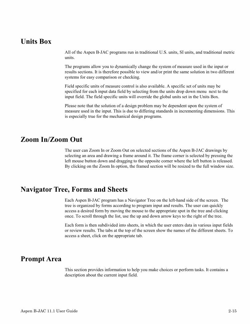
Units BoxAll of the Aspen B-JAC programs run in traditional U.S. units, SI units, and traditional metricunits.
The programs allow you to dynamically change the system of measure used in the input orresults sections. It is therefore possible to view and/or print the same solution in two differentsystems for easy comparison or checking.
Field specific units of measure control is also available. A specific set of units may bespecified for each input data field by selecting from the units drop down menu next to theinput field. The field specific units will override the global units set in the Units Box.
Please note that the solution of a design problem may be dependent upon the system ofmeasure used in the input. This is due to differing standards in incrementing dimensions. Thisis especially true for the mechanical design programs.
Zoom In/Zoom OutThe user can Zoom In or Zoom Out on selected sections of the Aspen B-JAC drawings byselecting an area and drawing a frame around it. The frame corner is selected by pressing theleft mouse button down and dragging to the opposite corner where the left button is released.By clicking on the Zoom In option, the framed section will be resized to the full window size.
Navigator Tree, Forms and SheetsEach Aspen B-JAC program has a Navigator Tree on the left-hand side of the screen. Thetree is organized by forms according to program input and results. The user can quicklyaccess a desired form by moving the mouse to the appropriate spot in the tree and clickingonce. To scroll through the list, use the up and down arrow keys to the right of the tree.
Each form is then subdivided into sheets, in which the user enters data in various input fieldsor review results. The tabs at the top of the screen show the names of the different sheets. Toaccess a sheet, click on the appropriate tab.
Prompt AreaThis section provides information to help you make choices or perform tasks. It contains adescription about the current input field.

2-16 Aspen B-JAC 11.1 User Guide
Status BarThis bar displays information about the current program status and input field status. If valueentered for an input field is outside the normal range, a warning will be display in the StatusBar with the recommend value limits.
Program Input
Key FunctionsName Description
F1 Activates the Help system
Arrow Keys Moves the location of the cursor within an input field and scrolls throughthe options in a given list
Delete Key Deletes the character at the current cursor position and shifts theremainder of the input
Home Key Returns the cursor to the beginning of the input field
End Key Moves the cursor to the end of the input field
Forward Tab Key Scrolls the user through the input fields of a form
Backward Tab Key Move cursor back to previous field
Control + Delete Keys Erases the characters from the cursor position to the end of the input field
Page Up/Page DownKeys
Scrolls the user through the forms of the Menu Tree
Backspace Key Deletes the character to the left of the current cursor position in an inputfield

Aspen B-JAC 11.1 User Guide 2-17
Input FieldsSheets are made up of input fields and their descriptions. For each field, the user (1) entersdata, (2) chooses from a given list of options, or (3) checks the cell if appropriate. The cursorcan be moved from one input field to another by using the Tab key, Enter key, arrow keys, orthe mouse.
You can navigate through a input form by using the Tab key or Enter key which will take youto the next required input field or you can select the items with the mouse. To navigatethrough an input field grid, such as for physical properties, or nozzle connections, you can usethe Enter key which will move the cursor down to the next field in a column, or you can usethe arrow keys to direct the cursor, or you can use the mouse to select the input field.
The input fields consist of the following types:• User defined. You enter the value such as a temperature or operating pressure.• User defined with suggested values. You can input a value or select from a list of
typical values for the input which are available in a drop down selection menu. You canaccess by the drop down menu by clicking on the input field with the mouse and thenselect the down arrow displayed. You can select an item in the drop down menu by usingthe up and down arrow keys or by selecting with the mouse.
• Available program selections. You select from a drop down menu list or options listdisplayed on the input form. You can select an item in the drop down menu by using theup and down arrow keys or by selecting with the mouse.
• Many of the input fields have graphical support. As you select from the availablemenu options, a sketch of the selection will appear next to the input field.
There are two types of data that can be entered: alphanumeric and numeric. Alphanumericfields accept any printable character. Numeric fields accept only the digits zero through nineplus certain special characters such as: + - .
You can enter letters of the alphabet in either upper case or lower case. The letters areretained in the case entered for headings, remarks, and fluid names.
Whole numbers can be entered without a decimal point. Numbers over one thousand shouldnot have punctuation to separate the thousands or millions. Decimal numbers less than 1 maybe entered with or without the leading zero. Scientific notation (E format) can be used.
n Examples of Valid Entries Examples of Invalid Entries
125 15/16
289100 289,100
-14.7 0.9375

2-18 Aspen B-JAC 11.1 User Guide
If an input field is identified as optional input (white background), you may leave the fieldblank and the program will use a default value. For physical properties where you want theprogram to retrieve the value from the physical properties databank (see Search a Databank),you should leave the input field blank. In many cases, you can get additional descriptiveinformation on an item by pressing F1, the Help key.
Required input fields will be identified by a green background color for the input field.Optional input fields will have a white background. Any inputted value that exceeds a normalrange limit will be highlighted with a red background. Note that the program will still acceptand use a value outside the normal range. If a folder or tab is not complete, a red X will beshown on the respective folder in the Navigation Tree and on the Tab label.
Units of Measure – Field Specific All of the Aspen B-JAC programs run in traditional U.S. units, SI units, and traditional metricunits. The global setting for units is set in the Units Box located in the Tools Bar.
The programs allow you to dynamically change the system of measure used in the input orresults sections. It is therefore possible to view and/or print the same solution in two differentsystems for easy comparison or checking.
Field specific units of measure control is also available. A specific set of units may bespecified for each input data field by selecting from the units drop down menu next to theinput field. The field specific units will override the global units set in the Units Box. Notethat you can input the value in one set of units and then select an alternate unit from the dropdown units menu, and the inputted value will be converted.
Please note that the solution of a design problem may be dependent upon the system ofmeasure used in the input. This is due to differing standards in incrementing dimensions. Thisis especially true for the mechanical design programs.

Aspen B-JAC 11.1 User Guide 2-19
Databank Reference You can search for an item in the Chemical Component or Material of ConstructionDatabanks. Click on the Search button located on databank reference form to open the searchutility.
To find an item in the list, type in the first few letters of the material name. Or, scroll throughthe material list using the up and down arrows to the right of the field. You can also specify asearch preference, database, material class and material type. Click on the desired material. Inthe Component list, click on the desired component and press Set to match it with the selectedreference. You can also erase a reference from the component list by clicking on thecomponent and pressing Clear.
The components in the databank have a component name which is up to 32 characters long, achemical formula or material specification. You use these for the databank reference. Werecommend that you do not use the chemical formula, because the formula may not be aunique reference. You should use the appropriate reference exactly as it appears in thedatabank directory.

2-20 Aspen B-JAC 11.1 User Guide
Range Checks After data is entered in an input field, the program will check the specified data against a highand low value range. If a value falls outside this range, the input field will turn red and awarning message will be displayed at the bottom left hand of the screen. This does not meanthe program will not accept this data. It merely suggests that you should check the data foraccuracy. If the data is correct, continue with data input.
Change Codes Several of the programs have a form for change codes. You can use this form to insert fourletter codes and numeric values to specify input data which is not included in the regular inputscreens. Refer to the Change Code section in the individual Program Guide. First type thechange code, then an equals sign (“=”), then the numeric value. For example: SENT=2.
It also possible to provide a Super Change Code by defining the change codes to be appliedto a design in a separate ASCII file and referencing the file as follows in the Change Codeinput field: File="Filename"
The Database Concept We suggest that you use the same input file for all Aspen B-JAC programs for a specific heatexchanger design problem. Save the input data in a convenient filename that can be accessedby all the Aspen B-JAC programs.
Using the Transfer function under the Run menu, you can add data to the input for use withother programs. For example, you can use Hetran to thermally design a shell and tube heatexchanger, and then request that the chosen design be transferred to another program such asHetran into Aerotran, Hetran into Teams, or Teams into Ensea. In this way the appropriatedesign data is directly available to other programs.
This concept also makes it easy for you to compare design solutions in different types of heatexchangers. You can run Hetran to design a shell and tube heat exchanger and then, with verylittle additional input data, run Aerotran to design an air-cooled heat exchanger.

Aspen B-JAC 11.1 User Guide 2-21
Program Output The primary forms of output from the Aspen B-JAC programs are display output, printedoutput, and drawings. Details on the output can be found in the Results section of theindividual Aspen B-JAC program’s user guide.
Display Output You can evaluate the results of the program’s execution to determine if any changes in thesolution are required. Scroll through the forms in the Results section of the Menu Tree to takea look at the program output. Each form may have multiple sheets of results, which can beaccessed by clicking on the different tabs at the top of the screen.
Printed Output To print a file, choose Print under the File menu. When the print screen comes up, review theprinting options, make any desired changes, and click OK.
Drawings Many of the Aspen B-JAC programs’ output include drawings. Drawings generated by theTEAMS program may be exported to CAD programs.

2-22 Aspen B-JAC 11.1 User Guide
Help Facility The Aspen B-JAC software includes extensive help facilities, which have been designed tominimize the need for printed documentation.
You may access the help facility in the following ways:
General Help This level includes information that applies to all of the Aspen B-JAC programs. You canaccess the general help index by selecting the Help button from the Menu Bar at any time inthe program. You may select the Help Contents to select from the list of topics or you mayselect to Search for Help On a specific topic.
Field Specific General Help Topic By selecting an input field with the mouse and then pressing the F1 key, the general help willopen at the appropriate index location for that subject.
Field Specific "What's This?" Help You can obtain input field specific help by selecting the What's This ? in the Tool Bar anddragging the ? to the input field that you need information.
Importing/Exporting Design Data Information to Other OLECompliant Applications
The Aspen B-JAC input/results file may be exported to other OLE compliant systems for usewith other programs via various automation utilities that are available. An exampleautomation file has been provided in the example sub-directory, "XMP", located with theAspen B-JAC program files.
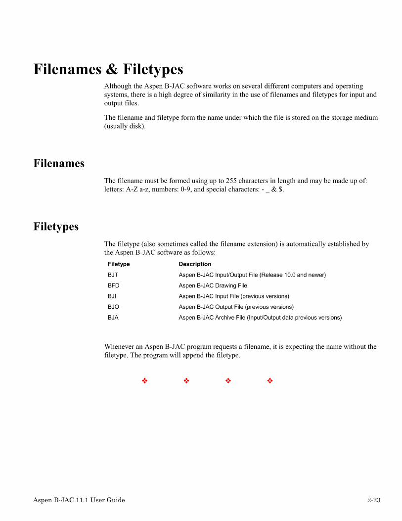
Aspen B-JAC 11.1 User Guide 2-23
Filenames & Filetypes Although the Aspen B-JAC software works on several different computers and operatingsystems, there is a high degree of similarity in the use of filenames and filetypes for input andoutput files.
The filename and filetype form the name under which the file is stored on the storage medium(usually disk).
Filenames The filename must be formed using up to 255 characters in length and may be made up of:letters: A-Z a-z, numbers: 0-9, and special characters: - _ & $.
Filetypes The filetype (also sometimes called the filename extension) is automatically established bythe Aspen B-JAC software as follows: Filetype Description
BJT Aspen B-JAC Input/Output File (Release 10.0 and newer)
BFD Aspen B-JAC Drawing File
BJI Aspen B-JAC Input File (previous versions)
BJO Aspen B-JAC Output File (previous versions)
BJA Aspen B-JAC Archive File (Input/Output data previous versions)
Whenever an Aspen B-JAC program requests a filename, it is expecting the name without thefiletype. The program will append the filetype.
❖ ❖ ❖ ❖

2-24 Aspen B-JAC 11.1 User Guide

Aspen B-JAC 11.1 User Guide 3-1
3 Aspen Hetran
IntroductionAspen Hetran is a program for the thermal design, rating, and simulation of shell and tubeheat exchangers. It encompasses the great majority of industrial shell and tube heat exchangerapplications, including most combinations of no phase change, condensation, andvaporization.
In the design mode, Aspen Hetran searches for the optimum heat exchanger to satisfy thespecified heat duty within the limits of the allowable pressure drops, velocities, shelldiameters, tube lengths, and other user specified restrictions. In the design mode, the programproduces a detailed optimization path, which shows the alternatives considered by theprogram as it searches for a satisfactory design. These "intermediate designs" indicate theconstraints that are controlling the design and point out what parameters you could modify toreduce the size of the exchanger.
The rating mode is used to check the performance of an exchanger with fully specifiedgeometry under any desired operating conditions. The program will check to see if there issufficient surface area for the process conditions specified and notify the user if the unit isunder surfaced.
For the simulation mode, you will specify the heat exchanger geometry and the inlet processconditions and the program will predict the outlet conditions for both streams.
The Aspen Hetran program has an extensive set of input default values built-in. This allowsyou to specify a minimum amount of input data to evaluate a design.
For complex condensation and/or vaporization, where the program requires vapor-liquidequilibrium data and properties at many temperature points, you can enter the data directlyinto the input file, or you can have Aspen Hetran generate the curve.
The program includes a basic mechanical design to determine the shell and head cylinderthickness and a reasonable estimate of the tubesheet thickness. However, a detailedmechanical design goes beyond the scope of the Aspen Hetran program. That is the job of theAspen Teams program, which can be easily interfaced with the Aspen Hetran program.

3-2 Aspen B-JAC 11.1 User Guide
Aspen Hetran incorporates all applicable provisions of the standards of the TubularExchanger Manufacturers Association (TEMA) and can be used to design all TEMAexchanger types. The program also includes many of the ANSI, DIN, and ISO standards thatapply to heat exchangers.
A cost estimate is provided for each design to give you feedback on the cost impact of designchanges. The cost estimate routine is the same as the one in the Qchex program and uses thesame material cost database.
Aspen Hetran is an interactive program, which means you can evaluate design changes as yourun the program. The program will guide you through the input, calculation, display of results,design changes, and selection of printed output.
Thermal Scope
No Phase Change
Liquid or gas, Newtonian fluids only
Condensation
Shell or tube side
Horizontal or vertical
Single or multicomponent condensables
With or without noncondensables
With or without liquid entering
Isothermal, linear, or nonlinear
Desuperheating of vapor
Subcooling below the bubble point
Straight through or knockback reflux

Aspen B-JAC 11.1 User Guide 3-3
Vaporization
Shell or tube side
Horizontal or vertical
Single or multi-component
With or without gases entering
Isothermal, linear, or nonlinear
Liquid preheating
Superheating above dew point
Pool boiling (shell side, horizontal only)
Forced circulation
Natural circulation (thermosiphon)
Falling film evaporation
Mechanical Scope
Front Head Types
TEMA Types: A, B, C, N, D
Shell Types
TEMA Types: E, F, G, H, J, K, X
Rear Head Types
TEMA Types: L, M, N, P, S, T, U, W
Special Types
Vapor & distributor belts, double tubesheets, hemispherical heads
Arrangements
Any number of shells in series or parallel

3-4 Aspen B-JAC 11.1 User Guide
Exchanger Positions
Horizontal or vertical
Construction Materials
Most common materials are built-in
Shell Diameter
No limit; in design mode the program will optimize
A minimum and maximum can be specified by the user
Any increment can be specified by the user
Baffle Types
Segmental baffles - single, double, triple
No tubes in window including intermediate supports
Grid baffles - rod, strip
Baffle Spacing
No limit; in design mode the program will optimize
A minimum and maximum can be specified by the user
The program checks for baffle & nozzle conflicts
Baffle Cut
15 to 45% of shell diameter (single segmental)
If not specified the program will choose
Impingement Protection
External or internal
In nozzle dome or distributor belt
Program checks for requirement

Aspen B-JAC 11.1 User Guide 3-5
Tube Diameter
No limit
Tube Length
No limit; in design mode the program will optimize
A minimum and maximum can be specified by the user
Any increment can be specified by the user
Tube Passes
1 to 16; in design mode the program will optimize
A minimum and maximum can be specified by the user
The increment can be even or odd passes
Pass Layout Types
Quadrant, mixed, ribbon
In design mode the program will optimize to the pass type with the most tubes
Tube Pitch
No limit; the program will default to a standard minimum
Tube Patterns
Triangular, rotated triangular, square, rotated square
Number of Tubes
Maximum of 400 tube rows
In design mode the program precisely determines the tube count
In rating mode the program checks the number of tubes specified

3-6 Aspen B-JAC 11.1 User Guide
Tube Wall Thickness
No limit; average or minimum wall
The program will check against design pressure
Tube Types
Plain
Integral circumferentially externally finned tubes
Commercial standards are built-in or the
Fin configuration can be specified
Twisted tape tube inserts
Nozzle Sizes
The program determines or the user can specify
Clearances
The program defaults to TEMA values for tube hole, baffle, and pass partition clearances
The user can specify the clearances

Aspen B-JAC 11.1 User Guide 3-7
Input
Problem DefinitionThe Problem Definition Section is subdivided into three headings: Description, ApplicationOptions, and Process Data.
Description
Headings
Headings are optional. You can specify from 1 to 5 lines of up to 75 characters per line. Theseentries will appear at the top of the TEMA specification sheet. You can have this input pre-formatted, by specifying your preferences for headings from the Program Settings in theTools menu.
Fluid names
This descriptive data is optional, but we highly recommend always entering meaningful fluiddescriptions, because these fluid names will appear with other input items to help you readilyidentify to which fluid the data applies. These names also appear in the output, especially theTEMA specification sheet. Each name can be up to 19 characters long and can containmultiple words.
Remarks
The remarks are specifically for the bottom of the output of the TEMA specification sheet.They are optional and each line can be up to 75 characters long.

3-8 Aspen B-JAC 11.1 User Guide
Application Options
Hot side application
Liquid, no phase change: Application covers a liquid phase fluid that does not change phasein the exchanger.
Gas, no phase change: Application covers a gas phase fluid that does not change phase inthe exchanger.
Narrow range condensation: Application covers the cases where the condensing side filmcoefficient does not change significantly over the temperature range. Therefore, thecalculations can be based on an assumed linear condensation profile. This class isrecommended for cases of isothermal condensation and cases of multiple condensableswithout noncondensables where the condensing range is less than 6°C (10°F).
Multi-component condensation: Application covers the other cases of condensation wherethe condensing side film coefficient changes significantly over the condensing range.Therefore, the condensing range must be divided into several zones where the properties andconditions must be calculated for each zone. This class is recommended for all cases wherenoncondensables are present or where there are multiple condensables with a condensingrange of more than 6°C (10°F).
Saturated steam: Application covers the case where the hot side is pure steam, condensingisothermally.
Falling film liquid cooler: Application covers the case where the fluid is flowing downwardand being cooled.
Condensation curve
You can input a vapor/liquid equilibrium curve or have the program calculate the curve usingideal gas laws or several other non-ideal methods.
Condenser type
Most condensers have the vapor and condensate flow in the same direction. However, forsome special applications where you want to minimize the amount of subcooling you canselect a knockback reflux condenser type. The condensate formed flows back towards thevapor inlet. With this type of condenser, you should consider using the differentialcondensation option if the program calculates the condensation curve.

Aspen B-JAC 11.1 User Guide 3-9
Cold side application
Liquid, no phase change: Application covers a liquid phase fluid that does not change phasein the exchanger.
Gas, no phase change: Application covers a gas phase fluid that does not change phase inthe exchanger.
Narrow range vaporization: Application covers the cases where the vaporizing side filmcoefficient does not change significantly over the temperature range. Therefore, thecalculations can be based on an assumed linear vaporization profile. This class isrecommended for cases of single components and cases of multiple components where thevaporizing range is less than 6°C (10°F).
Multi-component vaporization: Application covers the other cases of vaporization wherethe vaporizing side film coefficient changes significantly over the vaporizing range.Therefore, the vaporizing range must be divided into several zones where the properties andconditions must be calculated for each zone. This class is recommended for cases where thereare multiple components with a vaporizing range of more than 6°C (10°F).
Vaporization curve
You can input a vapor/liquid equilibrium curve or have the program calculate the curve usingideal gas laws or several other non-ideal methods.
Vaporizer type
Pool boiling: Pool boiling is restricted to the shell side and must be horizontal. It can be in akettle or a conventional shell with a full bundle or a partial bundle where tubes are removedfor disengagement space.
Thermosiphon: The thermosiphon can vaporize on the shell side (horizontal) or the tubeside (vertical or horizontal). The hydraulics of the thermosiphon design are critical for properoperation. You can specify the relationship of the heat exchanger to the column and theassociated piping in the input (see Thermosiphon Piping) or the program will select the pipingarrangement and dimensions.
Forced circulation: Forced circulation can be on either shell or tube side. Here the fluid ispumped through and an allowable pressure drop is required input. This can be for a oncethrough vaporizer.
Falling film: Falling film evaporation can be done only on the tube side in a vertical positionwhere the liquid enters the top head and flows in a continuous film down the length of thetube. Part of the liquid is vaporized as it flows down the tube. Normally the vapor formed alsoflows down the tube due to the difference in pressure between the top head and the bottomhead. This type of vaporizer helps minimize bubble point elevation and minimizes pressuredrop.

3-10 Aspen B-JAC 11.1 User Guide
Location of hot fluid
This required input identifies on which side to put the hot fluid. You can change this duringexecution of the Aspen Hetran program, so it is easy to compare the two possibilities.
As a general guideline, allocate fluids with these preferences:
shell side: more viscous fluid, cleaner fluid, lower flow rate
tube side: more corrosive fluid, higher pressure fluid, higher temperature fluid, dirtier fluid,more hazardous fluid, more expensive fluid.
Program mode
Design Mode: In design mode, you specify the performance requirements, and the programsearches for a satisfactory heat exchanger configuration.
Rating Mode: In rating mode, you specify the performance requirements and the heatexchanger configuration, and the program checks to see if that heat exchanger is adequate.
Simulation Mode: In simulation mode, you specify the heat exchanger configuration and theinlet process conditions, and the program predicts the outlet conditions of the two streams.
Select from standard file: You can specify a exchanger size standards file, a file whichcontains a list of standard heat exchanger sizes available to the user. The Hetran program willselect an exchanger size from the list that satisfies the performance requirements. Thestandard files can be generated in the Tools / Data Maintenance / Heat Exchanger Standardssection.
Process Data
Fluid quantity, total
Input the total flow rates for the hot and cold sides.
For no phase change, the flow rates can be left blank and the program will calculate therequired flow rates to meet the specified heat load or the heat load on the opposite side. Alltemperatures must be specified if the flow rates are omitted.
For phase change applications, the total flow rate should be at least approximated. Theprogram will still calculate the total required flow rate to balance the heat loads.

Aspen B-JAC 11.1 User Guide 3-11
Vapor quantity
For change in phase applications, input vapor flow rates entering or leaving the exchanger forthe applicable hot and/or cold sides. The program requires at least two of the three followingflow rates at the inlet and outlet: vapor flow, liquid flow, or total flow. It can then calculatethe missing value.
Liquid quantity
For change in phase applications, input the liquid flow rates entering and/or leaving theexchanger for applicable hot and/or cold sides. The program requires at least two of the threefollowing flow rates at the inlet and outlet: vapor flow, liquid flow, total flow. It can thencalculate the missing value.
Temperature (in/out)
Enter the inlet and outlet temperatures for the hot and cold side applications.
For no phase change applications, the program can calculate the outlet temperature based onthe specified heat load or the heat load on the opposite side. The flow rate and the inlettemperature must be specified.
For narrow condensation and vaporization applications, an outlet temperature and associatedvapor and liquid flows is required. This represents the second point on the VLE curve, whichwe assume to be a straight line. With this information, the program can determine the correctvapor/liquid ratio at various temperatures and correct the outlet temperature or total flow ratesto balance heat loads.
Dew point / Bubble point
For narrow range condensation and narrow range vaporization, enter the dew point andbubble point temperatures for the applicable hot and/or cold side.
For condensers, the dew point is required but the bubble point may be omitted if vapor is stillpresent at the outlet temperature. For vaporizers, the bubble point is required but the dewpoint may be omitted if liquid is still present at the outlet temperature.
Operating pressure (absolute)
Specify the pressure in absolute pressure (not gauge pressure). Depending on the application,the program may permit either inlet or outlet pressure to be specified. In most cases, it shouldbe the inlet pressure. For a thermosiphon reboiler, the operating pressure should reflect thepressure at the surface of the liquid in the column.

3-12 Aspen B-JAC 11.1 User Guide
In the case of condensers and vaporizers where you expect the pressure drop to significantlychange the condensation or vaporization curves, you should use a pressure drop adjustedvapor-liquid equilibrium data. If you had Hetran calculate the curve, you can indicate toadjust the curve for pressure drop.
Heat exchanged
You should specify a value for this input field when you want to design to a specific heatduty.
If the heat exchanged is specified, the program will compare the hot and cold side calculatedheat loads with the specified heat load. If they do not agree within 2%, the program willcorrect the flow rate, or outlet temperature.
If the heat exchanged is not specified, the program will compare the hot and cold sidecalculated heat loads. If they do not agree within 2%, the program will correct the flow rate,or outlet temperature.
To set what the program will balance, click on the Heat Exchange Balance Options tab andselect to have the program change flow rate, outlet temperature, or to allow an unbalancedheat load.
Allowable pressure drop
Where applicable, the allowable pressure drop is required input. You can specify any value upto the operating pressure, although the allowable pressure drop should usually be less than40% of the operating pressure.
Fouling resistance
The fouling resistance will default to zero if you leave it unspecified. You can specify anyreasonable value. The program provides a suggestion list of typical values.
Heat Load Balance Options
This input allows you to specify whether you want the total flow rate or the outlet temperatureto be adjusted to balance the heat load against the specified heat load or the heat loadcalculated from the opposite side. The program will calculate the required adjustment.
There is also an option to not balance the heat loads, in which case the program will designthe exchanger with the specified flows and temperatures but with the highest of the specifiedor calculated heat loads.

Aspen B-JAC 11.1 User Guide 3-13
Physical Property DataThis section includes: Property Options, Hot Side Composition, Hot Side Properties, ColdSide Composition, Cold Side Properties
Property Options
Databanks: Hot Side and Cold Side
Properties from B-JAC Databank / User Specified properties / Interface propertiesfrom Aspen Plus: By selecting this option, you can reference the B-JAC Property Databank,specify your own properties in the Hot Side and Cold property sections, or have propertiesdirectly passed into the B-JAC file directly from Aspen Plus simulation program. The B-JACProperty Databank consists of over 1500 compounds and mixtures used in the chemicalprocess, petroleum, and other industries. You can reference the database by entering thecomponents for the Hot Side and/or Cold Side streams in the Composition sections. Use theSearch button to locate the components in the database. If you specify properties in the HotSide and/or Cold Side property sections, do not reference any compounds in the Hot Sideand/or Cold Side Composition sections unless you plan to use both the B-JAC Databankproperties and specified properties. Any properties specified in the property sections willoverride properties coming from a property databank. If properties have been passed into theB-JAC file from the Interface to a Aspen Plus simulation run, these properties will beshown in the Hot Side and/or Cold Side Property sections. If you have passed in propertiesfrom Aspen Plus, do not specify a reference to an *.APPDF file below since properties havealready been provided by the Aspen Plus interface in the specified property sections.
Aspen Properties Databank: Aspen B-JAC provides access to the Aspen Properties physicalproperty databank of compounds and mixtures. To access the databank, first create an Aspeninput file with stream information and physical property models. Run Aspen Plus and createthe property file, xxxx.APPDF. Specify the name of the property file here in the Hetran inputfile. Specify the composition of the stream in the Hetran Property Composition section.When the B-JAC program is executed, the Aspen Properties program will be accessed andproperties will be passed back into the B-JAC design file.
Default: Aspen B-JAC Databank / Specified Properties
Flash Option
If you are referencing the Aspen Properties databank, and providing the XXXX.APPDF file,specify the flash option you want Aspen Properties program to use with the VLE generation.Reference the Aspen Properties documentation for further detailed information on thissubject.
Default: Vapor-Liquid

3-14 Aspen B-JAC 11.1 User Guide
The Aspen Plus run file
If you are referencing the Aspen Properties databank, provide the XXXX.APPDF file. If thefile is not located in the same directory as your B-JAC input file, use the browse button to setthe correct path to the *.APPDF file.
Condensation Curve Calculation Method
The calculation method determines which correlations the program will use to determine thevapor-liquid equilibrium. The choice of method is dependent on the degree of non-ideality ofthe vapor and liquid phases and the amount of data available.
The methods can be divided into three general groups:
Ideal - correlations for ideal mixtures. The ideal method uses ideal gas laws for the vaporphase and ideal solution laws for the liquid phase. You should use this method when you donot have information on the degree of nonideality. This method allows for up to 50components.
Uniquac, Van Laar, Wilson, and NRTL - correlations for non-ideal mixtures which requireinteraction parameters. These methods are limited to ten components. The Uniquac, VanLaar, Wilson, and NRTL methods need binary interaction parameters for each pair ofcomponents. The Uniquac method also needs a surface parameter and volume parameter andthe NRTL method requires an additional Alpha parameter. The Wilson method is particularlysuitable for strongly non-ideal binary mixtures, e.g., solutions of alcohols with hydrocarbons.The Uniquac method is applicable for both vapor-liquid equilibrium and liquid-liquidequilibrium (immiscibles). It can be used for solutions containing small or large molecules,including polymers. In addition, Uniquac's interaction parameters are less temperaturedependent than those for Van Laar and Wilson.
Soave-Redlich-Kwong, Peng-Robinson, and Chao-Seader - correlations for non-idealmixtures which do not require interaction parameters. The Soave-Redlich-Kwong and Peng-Robinson methods can be used on a number of systems containing hydrocarbons, nitrogen,carbon dioxide, carbon monoxide, and other weakly polar components. They can also beapplied with success to systems which form an azeotrope, and which involve associatingsubstances such as water and alcohols. They can predict vapor phase properties at any givenpressure. The Chao-Seader method uses Redlich-Kwong equations for vapor phase non-ideality and an empirical correlation for liquid phase non-ideality. It is used with success inthe petroleum industry. It is recommended for use at pressures less than 68 bar (1000 psia)and temperatures greater than -18°C (0°F). The program uses the original Chao-Seadercorrelation with the Grayson-Streed modification. There is no strict demarcation betweenthese two methods since they are closely related. These methods allow for up to 50components.

Aspen B-JAC 11.1 User Guide 3-15
Condensation Curve Calculation Type
For a condensing stream, you should determine if your case is closer to integral or differentialcondensation.
Integral condensation assumes that the vapor and liquid condensate are kept close enoughtogether to maintain equilibrium, and that the condensate formed at the beginning of thecondensing range is carried through with the vapor to the outlet. Vertical tube sidecondensation is the best case of integral condensation. Other cases which closely approachintegral condensation are: horizontal tube side condensation, vertical shell side condensation,and horizontal shell side crossflow condensation (X-shell).
In differential condensation the liquid condensate is removed from the vapor, thus changingthe equilibrium and lowering the dew point of the remaining vapor. The clearest case ofdifferential condensation is seen in the knockback reflux condenser, where the liquidcondensate runs back toward the inlet while the vapor continues toward the outlet.
Shell side condensation in a horizontal E or J shell is somewhere between true integralcondensation and differential condensation. If you want to be conservative, treat these casesas differential condensation. However, the industry has traditionally designed them as integralcondensation.
More condensate will be present at any given temperature with integral condensation versusdifferential condensation. In the heat exchanger design, this results in a higher meantemperature difference for integral condensation compared to differential condensation.
Effect of pressure drop on condensation
The program will default to calculating the condensing curve in isobaric conditions (constantoperating pressure). If you are having the B-JAC Property program generate the VLE curve,you may specify non-isobaric conditions and the program will allocate the specified pressuredrop based on temperature increments along the condensing curve. The vapor/liquidequilibrium at various temperature points will be calculated using an adjusted operatingpressure.
Estimated pressure drop for hot side
Provide the estimated hot side pressure drop through the exchanger. The program will use thispressure drop to adjust the VLE curve, if you are using the B-JAC Property program togenerate the VLE curve. If actual pressure varies more than 20 percent from this estimatedpressure drop, adjust this value to the actual and rerun Hetran. The VLE calculation programwill not permit the condensate to re-flash. If calculations indicate that this is happening, theprogram will suggest using a lower estimated pressure drop.

3-16 Aspen B-JAC 11.1 User Guide
Vaporization Curve Calculation Method
The calculation method determines which correlations the program will use to determine thevapor-liquid equilibrium. The choice of method is dependent on the degree of nonideality ofthe vapor and liquid phases and the amount of data available.
The methods can be divided into three general groups:
Ideal - correlations for ideal mixtures. The ideal method uses ideal gas laws for the vaporphase and ideal solution laws for the liquid phase. You should use this method when you donot have information on the degree of non-ideality. This method allows for up to 50components.
Uniquac, Van Laar, Wilson, and NRTL - correlations for non-ideal mixtures which requireinteraction parameters. These methods are limited to ten components. The Uniquac, VanLaar, Wilson, and NRTL methods need binary interaction parameters for each pair ofcomponents. The Uniquac method also needs a surface parameter and volume parameter andthe NRTL method requires an additional Alpha parameter. The Wilson method is particularlysuitable for strongly non-ideal binary mixtures, e.g., solutions of alcohols with hydrocarbons.The Uniquac method is applicable for both vapor-liquid equilibrium and liquid-liquidequilibrium (immiscibles). It can be used for solutions containing small or large molecules,including polymers. In addition, Uniquac's interaction parameters are less temperaturedependent than those for Van Laar and Wilson.
Soave-Redlich-Kwong, Peng-Robinson, and Chao-Seader - correlations for non-idealmixtures that do not require interaction parameters. The Soave-Redlich-Kwong and Peng-Robinson methods can be used on a number of systems containing hydrocarbons, nitrogen,carbon dioxide, carbon monoxide, and other weakly polar components. They can also beapplied with success to systems which form an azeotrope, and which involve associatingsubstances such as water and alcohols. They can predict vapor phase properties at any givenpressure. The Chao-Seader method uses Redlich-Kwong equations for vapor phase non-ideality and an empirical correlation for liquid phase non-ideality. It is used with success inthe petroleum industry. It is recommended for use at pressures less than 68 bar (1000 psia)and temperatures greater than -18°C (0°F). The program uses the original Chao-Seadercorrelation with the Grayson-Streed modification. There is no strict demarcation betweenthese two methods since they are closely related. These methods allow for up to 50components.
Effect of pressure drop on vaporization
The program will default to calculating the vaporization curve in isobaric conditions (constantoperating pressure). If you are having the B-JAC Property program generate the VLE curve,you may specify non-isobaric conditions and the program will allocate the specified pressuredrop based on temperature increments along the vaporization curve. The vapor/liquidequilibrium at various temperature points will be calculated using an adjusted operatingpressure.

Aspen B-JAC 11.1 User Guide 3-17
Estimated pressure drop for cold side
Provide the estimated cold side pressure drop through the exchanger. The program will usethis pressure drop to adjust the VLE curve. If actual pressure varies more than 20% from thisestimated pressure drop, adjust this value to the actual and rerun Hetran.
Hot Side CompositionIf the stream physical properties are being accessed from the Aspen B-JAC databank or theprogram is calculating a vapor/liquid equilibrium curve (B-JAC Props or Aspen Properties);the stream composition must be defined in this table.
Hot side composition specification
Enter weight flow rate or %, mole flow rate or %, volume flow rate or %.
The composition specification determines on what basis the mixture physical propertiescalculations should be made.
Components
The components field identifies the components in the stream. Properties for components canbe accessed from the databanks by specifying the B-JAC Compound name. A "Search"facility has been provided to allow you to easily scan and select compounds from thedatabank. When the program is calculating a vapor/liquid equilibrium curve, you also havethe option of specifying individual component physical properties by using the "Source"entry. If this is used, the component field will be used to identify the component in the results.
Vapor in, Liquid in, Vapor out, Liquid out
These fields identify the composition of the stream in each phase and is dependant on theComposition Specification described above. You must specify the inlet compositions ifreferencing the databank for physical properties. If outlet compositions are not specified, theprogram will assume the same composition as the inlet. The data for each column isnormalized to calculate the individual components fraction.
Component Type
Component type field is available for all complex condensing applications. This field allowsyou to specify noncondensables and immiscible components. If you are not sure of thecomponent type, the program will attempt to determine if it is a noncondensable but ingeneral it is better to identify the type if known. If a component does not condense any liquidover the temperature range in the exchanger, it is best to identify it as a noncondensable.

3-18 Aspen B-JAC 11.1 User Guide
Source
The Source field is currently only available for components when the program is calculatingvapor/liquid equilibrium curves. The Source of the component may be "Databank" or "User"."Databank" indicates that all component properties will be retrieved from one of the B-JACdatabanks. "User" indicates that this component's physical properties are to be specified bythe user.
Component Properties Hot Side
Used only for calculating condensing curves within Aspen Hetran. Allows the user to overridedatabank properties or input properties not in the databank.
The physical properties required for various applications on the hot side are listed below:
Reference temperature Density vaporViscosity vapor Specific heat vaporThermal conductivity vapor Latent heatVapor pressure Density liquidViscosity liquid Specific heat liquidThermal conductivity liquid Surface tension liquidMolecular volume Molecular weightCritical pressure Critical temperature
Interaction Parameters
The Uniquac, Van Laar, Wilson, and NRTL methods need binary interaction parameters foreach pair of components. This data is not available from the databank and must be providedby the user. An example for the NRTL parameters is shown below.
NRTL Method --Example with 3 components (Reference Dechema)
NRTL “A” Interactive Parameters –Hetran inputted parameters
1 2 3
1 -- A21 A31
2 A12 -- A32
3 A13 A23 --

Aspen B-JAC 11.1 User Guide 3-19
NRTL “Alpha” Parameters –Hetran inputted parameters
1 2 3
1 -------- Alpha21 Alpha31
2 Alpha12 -------- Alpha32
3 Alpha13 Alpha23 --------
NRTL – Conversion from Aspen Properties parameters to Hetran parameters:
Aspen Properties NRTL Parameters – The parameters AIJ, AJI, DJI, DIJ, EIJ, EJI, FIJ, FJI,TLOWER, & TUPPER in Aspen Properties, which are not shown below, are not required forthe Hetran NRTL method.
Aspen Properties NRTL Interactive Parameters
Component I Component 1 Component 1 Component 2
Component J Component 2 Component 3 Component 3
BIJ BIJ12 BIJ13 BIJ23
BJI BJI12 BJI13 BJI23
CIJ CIJ12 CIJ13 CIJ23
“A” Interactive Parameters – Conversion from Aspen Properties to Hetran
1 2 3
1 -- A21=BJI12*1.98721 A31=BJI13*1.98721
2 A12=BIJ12*1.98721 -- A32-BJI23*1.98721
3 A13=BIJ13*1.98721 A23=BIJ23*1.98721 --
“Alpha” Parameters – Conversion from Aspen Properties to Hetran
1 2 3
1 -- Alpha21=CIJ12 Alpha31=CIJ13
2 Alpha12= CIJ12 -- Alpha32=CIJ23
3 Alpha13=CIJ13 Alpha23=CIJ23 --

3-20 Aspen B-JAC 11.1 User Guide
NRTL – Alpha parameters
The NRTL method requires binary interaction parameters for each pair of components and anadditional Alpha parameter. This data is not available from the databank. Reference thesection on Interactive Parameters for an example.
Uniquac – Surface & Volume parameters
The Uniquac method requires binary interaction parameters for each pair of components andalso needs a surface parameter and volume parameter. This data is not available from thedatabank.
Hot Side PropertiesThe physical properties required for the hot side fluids. Any inputted properties will overrideinformation coming from the B-JAC Property Database or Aspen Properties programs.
Temperature
If you are entering a vapor-liquid equilibrium curve, you must specify multiple temperaturepoints on the curve encompassing the expected inlet and outlet temperatures of the exchanger.The dew and bubble points of the stream are recommended. Condensation curves must havethe dew point and vaporization curves must have the bubble point. The first point on the curvedoes not have to agree with the inlet temperature although it is recommended. For simulationruns, it is best to specify the curve down to the inlet temperature of the opposite side.
You can specify as few as one temperature or as many as 13 temperatures. The temperaturesentered for no phase change fluids should at least include both the inlet and outlettemperatures. The inlet temperature of the opposite side fluid should also be included as a 3rd
temperature point for viscous fluids. Multiple temperature points, including the inlet andoutlet, should be entered when a change of phase is present.
Heat Load
For each temperature point you must specify a parameter defining the heat load. For heatload you may specify cumulative heat load, incremental heat load, or enthalpies.

Aspen B-JAC 11.1 User Guide 3-21
Vapor/Liquid Composition
For each temperature point you must also specify a parameter defining the vapor/liquidcomposition. For the composition, you may specify vapor flowrate, liquid flowrate, vapormass fraction, or liquid mass fraction. The program will calculate the other parameters basedon the entry and the total flow specified under process data. Vapor and liquid mass fractionsare recommended because they are independent of flow rates.
For complex condensers, the composition should be the total vapor stream includingnoncondensables.
Liquid and Vapor Properties
The necessary physical properties are dependent on the type of application. If you arereferencing the databank for a fluid, you do not need to enter any data on the correspondingphysical properties input screens. However, it is also possible to specify any property, even ifyou are referencing the databank. Any specified property will then override the value from thedatabank.
The properties should be self-explanatory. A few clarifications follow.
Specific Heat
Provide the specific heat for the component at the referenced temperature.
Thermal Conductivity
Provide the thermal conductivity for the component at the referenced temperature.
Viscosity
The viscosity requested is the dynamic (absolute) viscosity in centipoise or mPa*s (note thatcentipoise and mPa*s are equal). To convert kinematic viscosity in centistokes to dynamicviscosity in centipoise or mPa*s, multiply centistokes by the specific gravity.
The Aspen Hetran program uses a special logarithmic formula to interpolate or extrapolate theviscosity to the calculated tube wall temperature. However when a liquid is relatively viscous,say greater than 5 mPa*s (5 cp), and especially when it is being cooled, the accuracy of theviscosity at the tube wall can be very important to calculating an accurate film coefficient. Inthese cases, you should specify the viscosity at a third point, which extends the viscositypoints to encompass the tube wall temperature. This third temperature point may extend to aslow (if being cooled) or as high (if being heated) as the inlet temperature on the other side.

3-22 Aspen B-JAC 11.1 User Guide
Density
Be sure to specify density and not specific gravity. Convert specific gravity to density byusing the appropriate formula:
density, lb/ft3 = 62.4 * specific gravity
density, kg/m3 = 1000 * specific gravity
The density can also be derived from the API gravity, using this formula:
density, lb/ft3 = 8829.6 / ( API + 131.5 )
Surface Tension
Surface tension is needed for vaporizing fluids. If you do not have surface tension informationavailable, the program will estimate a value.
Latent Heat
Provide latent heat for change of phase applications.
Molecular Weight
Provide the molecular weight of the vapor for change of phase applications.
Diffusivity
The diffusivity of the vapor is used in the determination of the condensing coefficient for themass transfer method. Therefore, provide this property if data is available. If these are notknow, the program will estimate.
Noncondensables
Noncondensables are those vapor components in a condensing stream, which do not condensein any significant proportions at the expected tube wall temperature. Examples: hydrogen,CO2, Air, CO, etc.
The following properties need to be provided for the noncondensables or referenced from thedatabase: Specific Heat, Thermal Conductivity, Viscosity, Density, Molecular Weight, andMolecular Volume of the noncondensable.
The noncondensable flow rate is required if it has not been defined in the databankcomposition input.

Aspen B-JAC 11.1 User Guide 3-23
Cold Side CompositionIf the stream physical properties are being accessed from the Aspen B-JAC databank or theprogram is calculating a vapor/liquid equilibrium curve (B-JAC Props or Aspen Properties);the stream composition must be defined in this table.
Composition specification
Enter weight flow rate or % , mole flow rate or % , volume flow rate or %.
The composition specification determines on what basis the mixture physical propertiescalculations should be made.
Components
The components field identifies the components in the stream. Properties for components canbe accessed from the databanks by specifying the Aspen B-JAC Compound name. A "Search"facility has been provided to allow you to easily scan and select compounds from thedatabank. When the program is calculating a vapor/liquid equilibrium curve, you also havethe option of specifying individual component physical properties by using the "Source"entry. If this is used, the component field will be used to identify the component in the results.
Vapor In, Liquid In, Vapor Out, Liquid Out
These fields identify the composition of the stream in each phase and is dependant on theComposition Specification described above. You must specify the inlet compositions ifreferencing the databank for physical properties. If outlet compositions are not specified, theprogram will assume the same composition as the inlet. The data for each column isnormalized to calculate the individual component fraction.
Component Type
Specify the component type, inert, for each component. If you are not sure of the componenttype, the program will select for you but in general it is better to identify the type if known.
Source
The Source field is currently only available for components when the program is calculatingvapor/liquid equilibrium curves. The Source of the component may be "Databank" or "User.""Databank" indicates that all component properties will be retrieved from one of the B-JACdatabanks. "User" indicates that this component's physical properties are to be specified bythe user.

3-24 Aspen B-JAC 11.1 User Guide
Component Properties Cold SideUsed only for calculating vaporization curves within Aspen Hetran. Allows the user tooverride databank properties or input properties not in the databank.
The required physical properties required for the various applications on the cold side arelisted below:
Reference temperature Density vaporViscosity vapor Specific heat vaporThermal conductivity vapor Latent heatVapor pressure Density liquidViscosity liquid Specific heat liquidThermal conductivity liquid Surface tension liquidMolecular volume Molecular weightCritical pressure Critical temperature
Interaction Parameters
The Uniquac, Van Laar, Wilson, and NRTL methods need binary interaction parameters foreach pair of components. This data is not available from the databank.
NRTL – Alpha parameters
The NRTL method requires binary interaction parameters for each pair of components and anadditional Alpha parameter. This data is not available from the databank.
Uniquac – Surface & Volume parameters
The Uniquac method requires binary interaction parameters for each pair of components andalso needs a surface parameter and volume parameter. This data is not available from thedatabank.

Aspen B-JAC 11.1 User Guide 3-25
Cold Side PropertiesThe physical properties required for the hot side fluids. Any properties inputted will overrideinformation from B-JAC Props or Aspen Properties programs.
Temperature
If you are entering a vapor-liquid equilibrium curve, you must specify multiple temperaturepoints on the curve encompassing the expected inlet and outlet temperatures of the exchanger.The dew and bubble points of the stream are recommended. Condensation curves must havethe dew point and vaporization curves must have the bubble point. The first point on the curvedoes not have to agree with the inlet temperature although it is recommended. For simulationruns, it is best to specify the curve up to the inlet temperature of the opposite side.
You can specify as few as one temperature or as many as 13 temperatures. The temperaturesentered for no phase change fluids should at least include both the inlet and outlettemperatures. The inlet temperature of the opposite side fluid should also be included as a 3rd
temperature point for viscous fluids. Multiple temperature points, including the inlet andoutlet, should be entered when a change of phase is present.
Heat Load
For each temperature point you must specify a parameter defining the heat load. For heatload you may specify cumulative heat load, incremental heat load, or enthalpies.
Vapor/Liquid Composition
For each temperature point you must also specify a parameter defining the vapor/liquidcomposition. For the composition, you may specify vapor flowrate, liquid flowrate, vapormass fraction, or liquid mass fraction. The program will calculate the other parameters basedon the entry and the total flow specified under process data. Vapor and liquid mass fractionsare recommended because they are independent of flow rates.
Liquid and Vapor Properties
The necessary physical properties are dependent on the type of application. If you arereferencing the databank for a fluid, you do not need to enter any data on the correspondingphysical properties input screens. However, it is also possible to specify any property, even ifyou are referencing the databank. Any specified property will then override the value from thedatabank.
The properties should be self-explanatory. A few clarifications follow.

3-26 Aspen B-JAC 11.1 User Guide
Specific Heat
Provide the specific heat for the component at the referenced temperature.
Thermal Conductivity
Provide the thermal conductivity for the component at the referenced temperature.
Viscosity
The viscosity requested is the dynamic (absolute) viscosity in centipoise or mPa*s (note thatcentipoise and mPa*s are equal). To convert kinematic viscosity in centistokes to dynamicviscosity in centipoise or mPa*s, multiply centistokes by the specific gravity.
The Aspen Hetran program uses a special logarithmic formula to interpolate or extrapolate theviscosity to the calculated tube wall temperature. However when a liquid is relatively viscous,say greater than 5 mPa*s (5 cp), and especially when it is being cooled, the accuracy of theviscosity at the tube wall can be very important to calculating an accurate film coefficient. Inthese cases, you should specify the viscosity at a third point, which extends the viscositypoints to encompass the tube wall temperature. This third temperature point may extend to aslow (if being cooled) or as high (if being heated) as the inlet temperature on the other side.
Density
Be sure to specify density and not specific gravity. Convert specific gravity to density byusing the appropriate formula:
density, lb/ft3 = 62.4 * specific gravity
density, kg/m3 = 1000 * specific gravity
The density can also be derived from the API gravity, using this formula:
density, lb/ft3 = 8829.6 / ( API + 131.5 )
Surface Tension
Surface tension is needed for vaporizing fluids. If you do not have surface tension informationavailable, the program will estimate a value.
Molecular Weight
Provide the molecular weight of the vapor for change of phase applications.
Aspen B-JAC 11.1 User Guide 3-27
Diffusivity
If diffusivity values are not provided the program will estimate them. This property isimportant for the accurate prediction of condensing film coefficients using the mass transfermodel.
Critical Pressure
The critical pressure is the pressure above which a liquid cannot be vaporized no matter howhigh the temperature. For mixtures, the critical pressure should be the sum of the criticalpressures of each component weighted by their mole fractions.
This input is required to calculate the nucleate boiling coefficient. If you do not enter a valuefor the critical pressure, the program will estimate a value.
Vaporization curve adjustment for pressure
For certain applications (thermosiphons reboilers, pool boilers, etc.), it is advisable to adjustthe vaporization curve for pressure changes during the analysis of the exchanger. This inputspecifies the type of adjustment to be made.
Reference Pressure
For vaporization applications, a second reference pressure with the corresponding bubbleand/or dew point(s) is recommended. By inputting this data, the program can determine thechange in bubble point temperature with the change in pressure. This will be used to correctthe vaporization curve for pressure changes.
Bubble point at reference pressure
For vaporization applications, a bubble point at reference pressure may be optionallyspecified. The bubble point at reference pressure and bubble point at operating pressure areused to determine the change in bubble point temperature with change in pressure. This willbe used to correct the vaporization curve for pressure changes.
Dew point at reference pressure
For vaporization applications, a dew point at reference pressure may be optionally specified.The dew point at reference pressure and dew point at operating pressure are used to determinethe change in dew point temperature with change in pressure. This will be used to correct thevaporization curve for pressure changes.

3-28 Aspen B-JAC 11.1 User Guide
Exchanger GeometryThe Geometry Section is subdivided into six sections: Exchanger Type, Tubes, Bundle,Baffles, Rating/Simulation Data, Nozzles
Exchanger Type
Front head type
The front head type should be selected based upon the service needs for the exchanger. A fullaccess cover provided in the A, C, and N type heads may be needed if the tube side of theexchanger must be cleaned frequently. The B type is generally the most economical typehead.
Default: B Type

Aspen B-JAC 11.1 User Guide 3-29
Shell type
E type: Generally provides the best heat transfer but also the highest shell side pressure drop.Used for temperature cross applications where pure counter current flow is needed.
F type: This two pass shell can enhance shell side heat transfer and also maintain countercurrent flow if needed for temperature cross applications.
G type: Will enhance the shell side film coefficient for a given exchanger size.
H type: A good choice for low shell side operating pressure applications. Pressure drop canbe minimized. Used for shell side thermosiphons.
J type: Used often for shell side condensers. With two inlet vapor nozzles on top and thesingle condensate nozzle on bottom, vibration problems can be avoided.
K type: Used for kettle type shell side reboilers.
X type: Good for low shell side pressure applications. Units is provided with support plateswhich provides pure cross flow through the bundle. Multiple inlet and outlet nozzles or flowdistributors are recommended to assure full distribution of the flow along the bundle.
V type shell: This type is not currently part of the TEMA standards. It is used for very lowshell side pressure drops. It is especially well suited for vacuum condensers. The vapor belt isan enlarged shell over part of the bundle length.
Default: E type (except K type shell side pool boilers)

3-30 Aspen B-JAC 11.1 User Guide
Rear head type
The rear head type affects the thermal design, because it determines the outer tube limits andtherefore the number of tubes and the required number of tube passes.
Default: U type for kettle shells, M type for all others
Exchanger position
Specify that the exchanger is to be installed in the horizontal or vertical position.
Default: vertical for tube side thermosiphon; horizontal for all others

Aspen B-JAC 11.1 User Guide 3-31
Front cover type
Hemi
Cone Elbow Klopper Korbbogen
Flat TorisphericalE llip so idal`
This item will only appear when you have specified a B type front head. A flat bolted cover isassumed for the other front head types. This is included for the accuracy of the cost estimateand a more complete heat exchanger specification.
Default: ellipsoidal
Cover welded to a cylinder
The cover welded to a cylinder option determines if there is a cylinder between the front headflange (or tubesheet in the case of a hemispherical cover) and the attached cover. This isincluded for the accuracy of the cost estimate and a more complete heat exchangerspecification.
Default: yes, except when the cover is hemispherical

3-32 Aspen B-JAC 11.1 User Guide
Rear cover type
Flat Bolted
Elbow
Dished
Flat Welded TorisphericalEllipsoidal
Hemi Cone
Klopper Korbbogen
The flat bolted cover is for L, N, P and W type rear heads. The flat welded and form covers(except for the dished cover) are available on the M type rear heads. The dished andellipsoidal is available on the S and T rear heads. This is included for accuracy of the costestimate and a more complete heat exchanger specification.
Default: flat bolted for L, N, P, or W; ellipsoidal for M type; dished for S or T type
Cover welded to a cylinder
The cover welded to a cylinder option only applies to M type rear heads. For other cases it isignored. It determines if there is a cylinder between the rear head flange (or tubesheet in thecase of a hemispherical cover) and the attached cover. This is included for the accuracy of thecost estimate and a more complete heat exchanger specification.
Default: yes, except when the cover is hemispherical

Aspen B-JAC 11.1 User Guide 3-33
Shell cover type
Klopper Korbbogen
Flat Bolted Flat Welded Ellipsoidal Torispherical
Hemi
A shell cover type should be specified for a U-tube, S, or T type rear head exchangers. Shellcover may be welded directly to shell cylinder or bolted to the shell cylinder with a pair ofmating body flanges.
Default: Ellipsoidal for U-tube, S, T type rear heads
Tubesheet type
The tubesheet type has a very significant effect on both the thermal design and the cost.Double tubesheets are used when it is extremely important to avoid any leakage between theshell and tube side fluids. Double tubesheets are most often used with fixed tubesheetexchangers, although they can also be used with U-tubes and outside packed floating heads.
Double tubesheets shorten the length of the tube which is in contact with the shell side fluidand therefore reduce the effective surface area. They also affect the location of the shell sidenozzles and the possible baffle spacings.
The gap type double tubesheet has a space, usually about 150 mm (6 in.), between the inner(shell side) and outer (tube side) tubesheets. The integral type double tubesheet is made bymachining out a honeycomb pattern inside a single thick piece of plate so that any leaking

3-34 Aspen B-JAC 11.1 User Guide
fluid can flow down through the inside of the tubesheet to a drain. This type is rare, since itrequires special fabrication tools and experience.
Default: normal single tubesheet(s)
Tube to tubesheet joint
The tube to tubesheet joint does not affect the thermal design, but it does have a small effecton the mechanical design and sometimes a significant effect on the cost.
The most common type of tube to tubesheet joint is expanded only with 2 grooves. AlthoughTEMA Class C allows expanded joints without grooves, most fabricators will groove the tubeholes whenever the tubes are not welded to the tubesheet.
For more rigorous service, the tube to tubesheet joint should be welded. The most commonwelded joints are expanded and seal welded with 2 grooves and expanded and strengthwelded with 2 grooves.
Default: expanded only with 2 grooves for normal service; expanded and strength weldedwith 2 grooves for lethal service

Aspen B-JAC 11.1 User Guide 3-35
Include expansion joint
The specification of an expansion joint will not affect the thermal design calculations, but itwill have a significant effect on the cost. This item only applies to fixed tubesheet heatexchangers; it is ignored for all other types.
The calculations required to determine the need for an expansion joint are quite complex andare beyond the scope of the Hetran program. These calculations are part of the Teamsprogram. However the Hetran program will estimate the differential expansion between thetubes and the shell and make a simple determination on the need for an expansion joint if youuse the program default.
Default: program will choose based on estimated differential expansion
Flange type – hot side
The body flange type refers to the type of flanges that are attached to the shell cylinder for theshell side and the head cylinder(s) for the tube side. This item can have a significant effect onthe cost. The shell side body flange type (applicable to removable bundle designs only) alsocan have an effect on the thermal design, since the choice will determine how close the shellside nozzles can be to the tubesheet and therefore where the first and last baffles can belocated.
The program will default to a ring type body flange if cylinder is carbon steel. If the cylinderis alloy, the default will be a lap-joint type flange.
Ring Ring withOverlay
Lap Joint Hub
Default: Ring if attached to a carbon steel cylinder and not TEMA R Hub if attached to acarbon steel cylinder and TEMA R Lap joint if attached to an alloy cylinder

3-36 Aspen B-JAC 11.1 User Guide
Flange type – cold side
The body flange type refers to the type of flanges that are attached to the shell cylinder for theshell side and the head cylinder(s) for the tube side. This item can have a significant effect onthe cost. The shell side body flange type (applicable to removable bundle designs only) alsocan have an effect on the thermal design, since the choice will determine how close the shellside nozzles can be to the tubesheet and therefore where the first and last baffles can belocated.
The program will default to a ring type body flange if cylinder is carbon steel. If the cylinderis alloy, the default will be a lap-joint type flange.
Ring Ring withOverlay
Lap Joint Hub
Default: Ring if attached to a carbon steel cylinder and not TEMA R Hub if attached to acarbon steel cylinder and TEMA R Lap joint if attached to an alloy cylinder
Tubes
Tube type
The program covers plain tubes and external integral circumferentially finned tubes.
Externally finned tubes become advantageous when the shell side film coefficient is muchless than the tube side film coefficient. However there are some applications where finnedtubes are not recommended. They are not usually recommended for cases where there is highfouling on the shell side, or very viscous flow, or for condensation where there is a high liquidsurface tension.
The dimensional standards for Wolverine's High Performance finned tubes, are built into theprogram. These standard finned tubes are available in tube diameters of 12.7, 15.9, 19.1, and25.4 mm or 0.5, 0.625, 0.75, and 1.0 inch. Reference the appendix for available sizes.
Default: plain tubes

Aspen B-JAC 11.1 User Guide 3-37
Tube outside diameter
You can specify any size for the tube outside diameter, however the correlations have beendeveloped based on tube sizes from 10 to 50 mm (0.375 to 2.0 inch). The most common sizesin the U.S. are 0.625, 0.75, and 1.0 inch. In many other countries, the most common sizes are16, 20, and 25 mm.
If you do not know what tube diameter to use, start with a 20 mm diameter, if you work withISO standards, or a 0.75 inch diameter if you work with American standards. This size isreadily available in nearly all tube materials. The primary exception is for graphite which ismade in 32, 37, and 50 mm or 1.25, 1.5, and 2 inch outside diameters.
For integral low fin tubes, the tube outside diameter is the outside diameter of the fin.
Default: 19.05 mm or 0.75 inch
Tube wall thickness
You should choose the tube wall thickness based on considerations of corrosion, pressure,and company standards. If you work with ANSI standards, the thicknesses follow the BWGstandards. These are listed for your reference in the Appendix of this manual and in the Helpfacility.
The program defaults are a function of material per TEMA recommendations and a functionof pressure. The Aspen Hetran program will check the specified tube wall thickness forinternal pressure and issue a warning if it is inadequate.
The selections to the right of the input field are provided for easy selection using the mouse.The values are not limited to those listed.
Default: 0.065 in. or 1.6 mm for carbon steel; 0.028 in. or 0.7 mm for titanium; 0.180 in. or 5 mm for graphite;
0.049 in. or 1.2 mm for other materials
Tube wall roughness
The relative roughness of the inside tube surface will affect the calculated tube side pressuredrops. The program defaults a relatively smooth tube surface (5.91 x 10⁻⁵ inch). Acommercial grade pipe has a relative roughness of 1.97 x 10⁻³ inch.
Default: Smooth tube, 5.91 x 10⁻⁵ inch ( .0015 mm)

3-38 Aspen B-JAC 11.1 User Guide
Tube wall specification
In many countries, the tube wall thickness is specified as either average or minimum. Averagemeans the average wall thickness will be at least the specified thickness; typically thethickness may vary up to 12%. With minimum wall, all parts of the tube must be at least thespecified thickness.
In the U.S., most heat exchanger tubes are specified as average wall thickness. In othercountries, for example Germany, the standard requires minimum wall.
This item has a small effect on tube side pressure drop and a moderate effect on heatexchanger cost.
Default: average
Tube pitch
The tube pitch is the center to center distance between two adjacent tubes. Generally the tubepitch should be approximately 1.25 times the tube O.D. It some cases, it may be desirable toincrease the tube pitch in order to better satisfy the shell side allowable pressure drop. It is notrecommended to increase the tube pitch beyond 1.5 times the tube O.D. Minimum tubepitches are suggested by TEMA as a function of tube O.D., tube pattern, and TEMA class.The program will default to the TEMA minimum tube pitch, if you are designing to TEMAstandards. The DIN standards also cover tube pitch. The DIN tube pitches are a function oftube O.D., tube pattern, and tube to tubesheet joint. The program will default to the DINstandard if you are designing to DIN standards.
Default: TEMA minimum or DIN standard
Tube material
For available tube materials, reference the material section.
Default: Carbon steel

Aspen B-JAC 11.1 User Guide 3-39
Tube Pattern
The tube pattern is the layout of the tubes in relation to the direction of the shell sidecrossflow, which is normal to the baffle cut edge. The one exception to this is pool boiling ina kettle type reboiler where the tube supports are sometimes baffles with a vertical cut. Usetriangular when you want to maximize the shell side film coefficient and maximize thenumber of tubes, and shell side cleaning is not a major concern. If you must be able tomechanically clean the shell side of the bundle, then choose square or rotated square. Rotatedsquare will give the higher film coefficient and higher pressure drop, but it will usually havefewer tubes than a square layout. Rotated triangular is rarely the optimum, because it has acomparatively poor conversion of pressure drop to heat transfer. Square is recommended forpool boilers to provide escape lanes for the vapor generated.
Default: triangular - fixed tubesheet exchangers, square - pool boilers
Fin density
If you specify fin tubes as the tube type, then you must specify the desired fin density (i.e., thenumber of fins per inch or per meter depending on the system of measure). Since the possiblefin densities are very dependent on the tube material, you should be sure that the desired findensity is commercially available.
The dimensional standards for finned tubes made by Wolverine, and High Performance Tubeare built into the program. If you choose one of these, the program will automatically supplythe corresponding fin height, fin thickness, and ratio of tube outside to inside surface area. Ifyou do not choose one of the standard fin densities, then you must also supply the other findata, which follows in the input.

3-40 Aspen B-JAC 11.1 User Guide
The standard fin densities for various materials are:Carbon Steel 19
Stainless Steel 16, 28
Copper 19, 26
Copper-Nickel 90/10 16, 19, 26
Copper-Nickel 70/30 19, 26
Nickel Carbon Alloy 201 19
Nickel Alloy 400 (Monel) 28
Nickel Alloy 600 (Inconel) 28
Nickel Alloy 800 28
Hastelloy 30
Titanium 30
Admiralty 19, 26
Aluminum-Brass Alloy 687 19
Fin height
The fin height is the height above the root diameter of the tube.
Fin thickness
The fin thickness is the average fin thickness.
Surface area per unit length
The outside tube surface area per unit length of tube.
Average outside surface area / Unit length:
Tube O.D. 0.750 in 0.406-0.500 ft2/ft
Tube O.D. 19.05 mm 0.124-0.152 m2/m
Standard fin dimensions:
Fin Density 16-30 fins/in 630-1181 fins/m
Fin Height 0.0625-0.032 in 1.59-0.81 mm
Fin Thickness 0.011-0.012 in 0.28-0.31 mm

Aspen B-JAC 11.1 User Guide 3-41
Outside/Inside surface area ratio
The ratio of the tube outside to inside surface area is the developed surface area outsidedivided by the surface area inside per unit length.
Twisted Tape Insert Ratio of Length to Width for 180 Degree Twist
Provide the ratio of the length of tape required to make a 180 degree twist to the width of thetape. The smaller the ratio, the tighter the twist.
Twisted Tape Insert Width
Specify the width of twisted tape insert.
Tapered tube ends for knockback condensers
Select to have tapered tube ends at inlet tubesheet. Tapered tube ends promote bettercondensate drainage from the tubes and reduce the potential for flooding.

3-42 Aspen B-JAC 11.1 User Guide
Bundle
Shell entrance construction
Normally, it is advantageous to use a full tube layout, i.e., to place as many tubes as possiblewithin the outer tube limits. This maximizes the surface area within a given shell diameterand minimizes bypassing. However when this results in excessive velocities entering theshell, then it is recommended that some tubes near the inlet nozzle be removed or a dome ordistributor belt be installed.
If you choose the option to remove tubes within the nozzle projection, the program willeliminate any tubes, which would extend beyond the lowest part of the nozzle cylinder. Inmany cases, using this option will have no effect since nozzles, which are relatively small incomparison to the shell diameter (say smaller than 1/4 the shell diameter) will not extend tothe first row of tubes anyway.
A nozzle dome with a full layout reduces the velocity entering the shell, but does not effectthe velocity entering the bundle. A distributor belt with a full layout is the most effective wayto reduce entrance velocities, but it is usually the most expensive.
When you remove tubes so that the shell entrance area equals the inlet nozzle area, the tubelayout is the same as when installing an impingement plate on the bundle, although thepresence of the impingement plate is determined by another input item described next. This isusually a very effective way of decreasing entrance velocities.
Default: normal with full layout if no impingement plate; nozzle dome with full layout ifimpingement plate in nozzle dome; remove tubes so that shell entrance area equals inletnozzle area if impingement plate on bundle

Aspen B-JAC 11.1 User Guide 3-43
Shell exit construction
Normally, it is advantageous to use a full tube layout, i.e., to place as many tubes as possiblewithin the outer tube limits. This maximizes the surface area within a given shell diameterand minimizes bypassing. However when this results in excessive velocities exiting thebundle or shell, then it is recommended that some tubes near the outlet nozzle be removed ora dome or distributor belt be installed.
If you choose the option to remove tubes within the nozzle projection, the program willeliminate any tubes, which would extend beyond the lowest part of the nozzle cylinder. Inmany cases, using this option will have no effect since nozzles, which are relatively small incomparison to the shell diameter (say smaller than 1/4 the shell diameter) will not extend tothe first row of tubes anyway.
A nozzle dome with a full layout reduces the velocity exiting the shell, but does not effect thevelocity exiting the bundle. A distributor belt with a full layout is the most effective way toreduce exit velocities, but it is usually the most expensive.
When you remove tubes so that the shell entrance area equals the inlet nozzle area, it isusually a very effective way of decreasing exit velocities.
Default: same as shell entrance construction if inlet and outlet nozzles are at the sameorientation; otherwise, normal with full layout
Provide disengagement space in shell (pool boilers only)
If specified, the shell diameter will be increased to provide disengagement space for the vaporgenerated. If a kettle shell is specified, the program will always provide the disengagementspace.
Percent of shell diameter for disengagement (pool boilers only)
You can specify the percentage of disengagement space needed.

3-44 Aspen B-JAC 11.1 User Guide
Impingement protection type
The purpose of impingement protection is to protect the tubes directly under the inlet nozzleby deflecting the bullet shaped flow of high velocity fluids or the force of entrained droplets.TEMA recommends that inlet impingement protection be installed under the followingconditions:• When the rho*V2 through the inlet nozzle exceeds 2232 kg/(m*s2) or 1500 lb/(ft*s2) for
non-corrosive, non-abrasive, single phase fluids• When the rho*V2 through the inlet nozzle exceeds 744 kg/(m*s2) or 500 lb/(ft*s2) for
corrosive or abrasive liquids• When there is a nominally saturated vapor• When there is a corrosive gas• When there is two phase flow at the inlet
If you choose a plate on the bundle the program will automatically remove tubes under theinlet nozzle so that the shell entrance area equals the cross-sectional area of the nozzle. This isapproximately equal to removing any tubes within a distance of 1/4 the nozzle diameter underthe center of the nozzle. For purposes of calculating the bundle entrance velocity, the programdefaults to an impingement plate that is circular, unperforated, equal in diameter to the insidediameter of the nozzle, and approximately 3 mm or 1/8 in. thick.
An alternative is to put a plate in a nozzle dome, which means suspending the impingementplate in an enlarged nozzle neck, which may be a dome or a cone.
Both types have their advantages and disadvantages. If the plate is on the bundle, the flow ismore widely distributed, and there is neither the expense for the enlarged nozzle neck nor theincreased potential of fabrication problems when cutting a large hole in the shell (as can oftenhappen with vapor inlet nozzles). However, since tubes are removed, it may require largerdiameter shell, tubesheets, flanges, etc. Especially in cases where the tubesheets and/or shellare made of alloy and the inlet nozzle is not large, the impingement plate in the nozzle domemay be significantly less expensive. For some special applications, the plate may beperforated. The primary advantage being that the perforations will help reduce the velocityinto the bundle. The main concern with perforated plates is that flow through the holes couldcause localized erosion for certain tube materials.
Default: circular plate on bundle if condensation or vaporization is occurring on the shellside; none otherwise

Aspen B-JAC 11.1 User Guide 3-45
Impingement plate diameter
The program will use this input to determine the position and the dimension of theimpingement plate This input is not required if you have already specified the shell inletnozzle OD. The default is the shell inlet nozzle O.D.
Impingement plate length and width
You can specify a rectangular impingement plate size. The default is the shell inlet nozzleO.D. for length and width (square plate).
Impingement plate thickness
This input is required if you specify there is an impingement field. You can specify anythickness for the impingement plate. The default is 3 mm or 0.125 inch.
Impingement distance from shell ID
You can specify the distance from the shell inside diameter to the impingement plate. Thedefault is the top row of tubes.
Impingement clearance to tube edge
You can specify the distance from the impingement plate to the first row of tubes.
Impingement plate perforation area %
If you are using a perforated type impingement plate, you can specify the percent of area thatthe plate is perforated.

3-46 Aspen B-JAC 11.1 User Guide
Layout Options
Pass layout
Quadrant Mixed Ribbon
There are several possible ways to layout tubes for four or more passes. The primary effect onthe thermal design is due to the different number of tubes, which are possible for each type.
Quadrant layout has the advantage of usually (but certainly not always) giving the highesttube count. It is the required layout for all U-tube designs of four or more passes. The tubeside nozzles must be offset from the centerline when using quadrant layout. The program willautomatically avoid quadrant layout for shells with longitudinal baffles and 6, 10, or 14 pass,in order to avoid having the longitudinal baffle bisect a pass.
Mixed layout has the advantage of keeping the tube side nozzles on the centerline. It oftengives a tube count close to quadrant and sometimes exceeds it. The program willautomatically avoid mixed layout for shells with longitudinal baffles and 4, 8, 12, or 16passes.
Ribbon layout nearly always gives a layout with fewer tubes than quadrant or mixed layout. Itis the layout the program always uses for an odd number of tube passes. It is also the layoutpreferred by the program for X-type shells. The primary advantage of ribbon layout is themore gradual change in operating temperature of adjacent tubes from top to bottom of thetubesheet. This can be especially important when there is a large change in temperature on thetube side, which might cause significant thermal stresses in mixed and especially quadrantlayouts.
Default: program will optimize
Design symmetrical tube layout
Program will make the tube pattern as symmetrical as possible for the top to bottom.
Maximum % deviation in tubes per pass
This input determines the acceptable deviation from the median number of tubes per pass.This value is used in the tubesheet layout subroutine to determine the maximum number oftubes.

Aspen B-JAC 11.1 User Guide 3-47
Ideally, it is desirable to have the same number of tubes in each pass when there is no changeof phase on the tube side. However, for most layouts of more than two passes, this wouldrequire removing tubes which would otherwise fit within the outer tube limit. Since it ispreferable to maximize the surface area within a given shell and minimize the possible shellside bypassing, a reasonable deviation in tubes per pass is usually acceptable.
It is recommended that you avoid large deviations since this gives significantly differentvelocities in some passes and wastefully increases the pressure drop due to additionalexpansion and contraction losses. Since the Aspen Hetran program bases the tube sidecalculations on an average number of tubes per pass, such aberrations are not reflected in thethermal design.
Default: 5 %
Number of tie rods
The tie rods hold the spacers, which hold segmental baffles in place. This input has nomeaning in the case of grid baffles (rod and strip baffles).
TEMA has recommendations for a minimum number of tie rods, which is a function of theshell diameter. Additional tie rods are sometimes desirable to block bypassing along passpartition lanes or to better anchor double or triple segmental baffles.
The Aspen Hetran program will first try to locate the tie rods so that they do not displace anytubes. If this is not possible, it will then displace tubes as necessary. The program will onlylocate tie rods around the periphery of the bundle, not in the middle of the bundle.
Default: TEMA Standards
Number of sealing strip pairs
Sealing strips are used to reduce bypassing of the shell side flow around the bundle betweenthe shell ID and the outer most tubes. In fixed tubesheet (L, M, & N rear heads) and U-tubeheat exchangers the clearance between shell ID and the outer tube limit is comparativelysmall. Therefore sealing strips are seldom used for these types. In inside floating head (S & Trear heads), outside packed floating head (P rear head), and floating tubesheet (W rear head)heat exchangers, the potential for bypassing is much greater. In these cases sealing stripsshould always be installed.
The thermal design calculations in Aspen Hetran assume that sealing strips are always presentin P, S, T, & W type heat exchangers.
Default: none for L, M, N, U, & W types1 pair per 5 tube rows for S, T, & P types

3-48 Aspen B-JAC 11.1 User Guide
Minimum u-bend diameter
This is the minimum distance from tube center to tube center that a U-tube can be bent. Theprogram defaults to a generally safe minimum of three times the tube O.D. The true minimumis a function of the material, the tube wall thickness, and the bending process.
This has a significant effect on the thermal design, because it determines the number of tubesin a U-tube layout.
You can also use this input to force the program to simulate a U-tube layout where theinnermost U-tubes are installed at an angle other than the normal vertical plane (for 2 passes)or horizontal plane (for 4 or more passes). However, when doing this, the program will over-predict the number of tubes by one for each pass.
Default: three times the tube outside diameter
Pass partition lane width
The pass partition lane is the opening between passes as measured from the outermost edge ofthe tube of one pass to the outermost edge of a tube in the next pass. This necessary distanceis a function of the thickness of the pass partition plate and, in the case of U-tubes, theminimum U-bend diameter.
The program default equals the thickness of the pass partition plate plus 3 mm or 0.125 in.The thickness of the pass partition plate is determined according to the TEMA standards.
Default: pass partition plate thickness + 3 mm or 0.125 in.
Location of center tube in 1st row
You can select the tube position in the first row to be on the center line or off center. If set toprogram, the tube position will be set to maximize the number of tubes in the layout.
Default: program will optimize
Outer tube limit diameter
The outer tube limit (OTL) is the diameter of the circle beyond which no portion of a tubewill be placed. This input only applies to rating mode. In design mode, the program ignoresthis entry. An alternative means of controlling the OTL, in both rating and design mode is tospecify the "Shell ID to Baffle OD" and the "Baffle OD to outer tube limit" under DiametricClearances in the Clearances/Options Screen.
Default: program will calculate

Aspen B-JAC 11.1 User Guide 3-49
Layout Limits
Open space between shell ID and outermost tubeYou can control where the program will place tubes by specifying limits at the top of thebundle, bottom of the bundle, and/or both sides of the bundle. The tubesheet layout is alwayssymmetrical left to right, but it can be asymmetrical top to bottom. You can specify each limitas either a percentage of the shell inside diameter or as an absolute distance.
Default: limited by outer tube limit
Distance from tube centerYou can control the distances between the center tube rows and the horizontal / verticalcenterlines.
Default: program optimized
Clearances
Shell ID to baffle ODIt is recommended that you choose the program defaults for diametrical clearances that are inaccordance with the TEMA standards. If you want to override any of the default values,specify the desired diametrical clearance (two times the average gap).
Default: TEMA Standards
Baffle OD to outer tube limit
It is recommended that you choose the program defaults for diametrical clearances that are inaccordance with the TEMA standards. If you want to override any of the default values,specify the desired diametrical clearance (two times the average gap).
Default: TEMA Standards
Baffle tube hole to tube OD
Note that the tolerance on the baffle hole to tube clearance is highly dependent on the drillingequipment used. Therefore be careful when specifying a baffle hole to tube clearance lessthan 0.8 mm or 0.03125 in.
Default: TEMA standards

3-50 Aspen B-JAC 11.1 User Guide
Baffles
Baffle Type
SingleSegmental
DoubleSegmental
TripleSegmental Full Support
No Tubesin Window
Rod Strip
Baffle types can be divided up into two general categories - segmental baffles and gridbaffles. Segmental baffles are pieces of plate with holes for the tubes and a segment that hasbeen cut away for a baffle window. Single, double, triple, and no tubes in window areexamples of segmental baffles. Grid baffles are made from rods or strips of metal, which areassembled to provide a grid of openings through which the tubes can pass. The programcovers two types of grid baffles: rod baffles and strip baffles. Both are used in cases where theallowable pressure drop is low and the tube support is important to avoid tube vibration.
Segmental baffles are the most common type of baffle, with the single segmental bafflebeing the type used in a majority of shell and tube heat exchangers. The single segmentalbaffle gives the highest shell film coefficient but also the highest pressure drop. A doublesegmental baffle at the same baffle spacing will reduce the pressure drop dramatically(usually somewhere between 50% - 75%) but at the cost of a lower film coefficient. Thebaffles should have at least one row of overlap and therefore become practical for a 20 mm or0.75 in. tube in shell diameters of 305 mm (12 in.) or greater for double segmental and 610(24 in.) or greater for triple segmental baffles. (Note: the B-JAC triple segmental baffle isdifferent than the TEMA triple segmental baffle.)
Full Supports are used in K and X type shells where baffling is not necessary to direct theshell side flow.
No Tubes In Window is a layout using a single segmental baffle with tubes removed in thebaffle windows. This type is used to avoid tube vibration and may be further enhanced withintermediate supports to shorten the unsupported tube span. The standard abbreviation for notubes in the window is NTIW.
Rod Baffle design is based on the construction and correlations developed by PhillipsPetroleum. Rod baffles are limited to a square tube pattern. The rods are usually about 6 mm(0.25 in.) in diameter. The rods are placed between every other tube row and welded to a

Aspen B-JAC 11.1 User Guide 3-51
circular ring. There are four repeating sets where each baffle is rotated 90 degrees from theprevious baffle.
Strip Baffles are normally used with a triangular tube pattern. The strips are usually about 25mm (1 in.) wide and 3 mm (0.125 in.) thick. The strips are placed between every tube row.Intersecting strips can be notched to fit together or stacked and tack welded. The strips arewelded to a circular ring. Strip baffles are also sometimes referred to as nest baffles.
Default: single segmental except X shells; full support for X shell
Baffle cut (% of diameter)
The baffle cut applies to segmental baffles and specifies the size of the baffle window as apercent of the shell I.D. For single segmental baffles, the program allows a cut of 15% to45%. Greater than 45% is not practical because it does not provide for enough overlap of thebaffles. Less than 15% is not practical, because it results in a high pressure drop through thebaffle window with relatively little gain in heat transfer (poor pressure drop to heat transferconversion). Generally, where baffling the flow is necessary, the best baffle cut is around25%.
For double and triple segmental baffles, the baffle cut pertains to the most central bafflewindow. The program will automatically size the other windows for an equivalent flow area.
Refer to the Appendix for a detailed explanation of baffle cuts.
Default: single segmental: 45% for simple condensation and pool boiling; 25% for all others;double segmental: 28% (28/23); triple segmental: 14% (14/15/14)
Baffle cut orientation
Horizontal Vertical Rotated
The baffle orientation applies to the direction of the baffle cut in segmental baffles. It is verydependent on the shell side application for vertical heat exchangers; the orientation has littlemeaning or effect. It may affect the number of tubes in a multipass vertical heat exchanger.For horizontal heat exchangers it is far more important.
For a single phase fluid in a horizontal shell, the preferable baffle orientation of singlesegmental baffles is horizontal, although vertical and rotated are usually also acceptable. Thechoice will not affect the performance, but it will affect the number of tubes in a multipass

3-52 Aspen B-JAC 11.1 User Guide
heat exchanger. The horizontal cut has the advantage of limiting stratification ofmulticomponent mixtures, which might separate at low velocities.
The rotated cut is rarely used. Its only advantage is for a removable bundle with multiple tubepasses and rotated square layout. In this case the number of tubes can be increased by using arotated cut, since the pass partition lane can be smaller and still maintain the cleaning pathsall the way across the bundle. (From the tubesheet, the layout appears square instead ofrotated square.)
For horizontal shell side condensers, the orientation should always be vertical, so that thecondensate can freely flow at the bottom of the heat exchanger. These baffles are frequentlynotched at the bottom to improve drainage. For shell side pool boiling, the cut (if using asegmental baffle) should be vertical. For shell side forced circulation vaporization, the cutshould be horizontal in order to minimize the separation of liquid and vapor.
For double and triple segmental baffles, the preferred baffle orientation is vertical. Thisprovides better support for the tube bundle than a horizontal cut which would leave thetopmost baffle unsupported by the shell. However this can be overcome by leaving a smallstrip connecting the topmost segment with the bottommost segment around the baffle windowbetween the O.T.L. and the baffle O.D.
Default: vertical for double and triple segmental baffles;
vertical for shell side condensers;
vertical for F, G, H, and K type shells;
horizontal for all other cases

Aspen B-JAC 11.1 User Guide 3-53
Number of Intermediate Supports
Specify number of intermediate supports at the inlet, outlet and center spacing.
Intermediate supports are support plates or grids which are used to give additional support tothe tubes in order to avoid tube vibration. Grid supports can be used between baffles, at theinlet or outlet, or at the U-bend and with any type of baffle. Support plates at other positionscan only be used in conjunction with No Tubes In the Window (NTIW) baffles. Intermediatesupports are assumed to have an insignificant effect on the thermal performance. Theirpresence will however be considered in the vibration analysis.
Default: None
Type U-bend support
One or more supports can be placed at the U-bend to give additional support to the tubes inorder to avoid tube vibration.
Default: Full support at U-bend

3-54 Aspen B-JAC 11.1 User Guide
Distance from nearest support/baffle to tangent of U-bend
Provide the distance from the nearest support or baffle to the tangent point of the U-bends.Normally this clearance is a minimum of 3 inches.
Distance between partial supports at U-bend
If two partial supports at U-bend have been specified, you can indicate the spacing betweenthose supports.
Default: 6 inch spacing
U-bend mean radius
This mean radius will determine the unsupported tube span for the U-bends used in the tubevibration calculations. If not provided, the program will determine the mean radius basedupon the actual tube layout.
Default: Program calculated
Rod baffle dimensions
You can provide the ring dimensions and support rod diameter for rod type baffles. If youleave blank, the program will select these based upon the shell diameter.
Total length of support rods per baffle
Provide the total length of support rods per baffle so that the available flow area can bedetermined for heat transfer and pressure drop calculations.
Default: Program calculated

Aspen B-JAC 11.1 User Guide 3-55
Rating/Simulation DataIf you specified in the Application Options that a check rating or simulation of an existingexchanger is to be performed, the exchanger mechanical information shown below must beprovided. Other geometry parameters such as shell type and tube size will be set at defaultsunless specified in the geometry section of the input.
Shell outside diameter
Provide the actual shell outside diameter. For pipe size exchangers, it is recommended toinput a shell OD rather than an ID since the program will reference standard pipe schedules.For exchangers made of rolled and welded plate materials, the shell OD or ID may beinputted. For kettles, the shell diameter is for the small cylinder near the front tubesheet, notthe large cylinder.
Shell inside diameter
Provide the actual shell inside diameter. If the shell OD has been specified, it is recommendto leave the ID blank. For pipe size exchangers, it is recommended to input a shell OD ratherthan an ID since the program will reference standard pipe schedules. For exchangers made ofrolled and welded plate materials, the shell OD or ID may be inputted. For kettles, the shelldiameter is for the small cylinder near the front tubesheet, not the large cylinder.
Baffle spacing center to center
Specify the center to center spacing of the baffles in the bundle.
Baffle inlet spacing
Specify the inlet baffle spacing at the entrance to the bundle. For G, H, J, and X shell types,this is the spacing from the center of the nozzle to the next baffle. These types should have afull support under the nozzle. If left blank, the program will calculate the space based uponthe center to center spacing and the outlet spacing. If the outlet spacing is not provided, theprogram will determine the remaining tube length not used by the center to center spacing andprovide equal inlet and outlet spacings.
Baffle outlet spacing
Specify the outlet baffle spacing at the exit of the bundle. For G, H, J, and X shell types, thisis the spacing from the center of the nozzle to the next baffle. These types should have a fullsupport under the nozzle. If the outlet spacing is not provided, the program will determine theremaining tube length not used by the center to center spacing and provide equal inlet andoutlet spacings.

3-56 Aspen B-JAC 11.1 User Guide
Baffle number
The number of baffles is optional input. If you do not know the number of baffles, inlet, oroutlet spacing, you can approximate the number of baffles by dividing the tube length by thebaffle spacing and subtracting 1. However, if you do not know the number of baffles, it is bestto let the program calculate it, because it will also consider the tubesheet thickness and nozzlesizes. The number of baffles for G, H, and J type shells should include the baffle or fullsupport under the nozzle.
Tube length
Provide the tube length. The length should include the length of tubes in the tubesheets. ForU-tube exchangers, provide the straight length to the U-bend tangent point.
Tube number
Specify the number of tube holes in the tubesheet. This is the number of straight tubes or thenumber of straight lengths for a U-tube. If you specify the number, the program will check tomake sure that number of tubes can fit into the shell. If you do not specify it, the program willcalculate number of tubes using the tubesheet layout subroutine.
Tube passes
Provide the number of tube passes in the exchanger.
Shells in series
If you have multiple exchangers for a rating case, be sure to specify the appropriate number inparallel and/or series. Remember that the program requires that both shell side and tube sidebe connected in the same way (both in parallel or both in series). You can specify multipleexchangers in both parallel and series; for example you can have two parallel banks of threein series for a total of six heat exchangers.
Shells in parallel
If you have multiple exchangers for a rating case, be sure to specify the appropriate number inparallel and/or series. Remember that the program requires that both shell side and tube sidebe connected in the same way (both in parallel or both in series). You can specify multipleexchangers in both parallel and series; for example you can have two parallel banks of threein series for a total of six heat exchangers.

Aspen B-JAC 11.1 User Guide 3-57
Tube Layout Option
You can select to have the Hetran program generate a new tube layout every time the programruns or you can select to use an existing layout. For the second option, you must first runHetran to establish a layout and then select the option to use the existing layout for allsubsequent runs.
Default: create a new layout
Kettle outside diameter
Provide the actual kettle outside diameter. For pipe size exchangers, it is recommended toinput a kettle OD rather than an ID since the program will reference standard pipe schedules.For exchangers made of rolled and welded plate materials, the kettle OD or ID may beinputted.
Kettle inside diameter
Provide the actual kettle inside diameter. If the kettle OD has been specified, it is recommendto leave the ID blank. For pipe size exchangers, it is recommended to input a kettle OD ratherthan an ID since the program will reference standard pipe schedules. For exchangers made ofrolled and welded plate materials, the kettle OD or ID may be inputted.
Vapor belt outside diameter
Provide the actual vapor belt outside diameter. For pipe size exchangers, it is recommended toinput a vapor belt OD rather than an ID since the program will reference standard pipeschedules. For exchangers made of rolled and welded plate materials, the vapor belt OD orID may be inputted.
Vapor belt inside diameter
Provide the actual vapor belt inside diameter. If the vapor belt OD has been specified, it isrecommend to leave the ID blank. For pipe size exchangers, it is recommended to input avapor belt OD rather than an ID since the program will reference standard pipe schedules. Forexchangers made of rolled and welded plate materials, the vapor belt OD or ID may beinputted.
Vapor belt length
The length of the vapor belt is approximately two thirds the length of the shell. The lengthspecified will affect the entrance area pressure drop.

3-58 Aspen B-JAC 11.1 User Guide
Shell cylinder thickness
Provide the actual shell cylinder thickness. If the shell OD has been provided, the programwill use the cylinder thickness to calculate a shell ID and establish the OTL and tube countfor the exchanger.
Front head cylinder thickness
Provide the actual front head cylinder thickness.
Front tubesheet thickness
Provide the actual front tubesheet thickness. The program will use the tubesheet thickness todetermine the effective tube length for effective surface area calculations.
Rear tubesheet thickness
Provide the actual rear tubesheet thickness. The program will use the tubesheet thickness todetermine the effective tube length for effective surface area calculations.
Baffle thickness
Provide the actual baffle thickness.
Tube Layout
Once you have a specified an exchanger geometry and executed the Hetran in the RatingMode, you can interactively make modifications to the tube layout. Tubes: Tubes can beremoved from the layout by clicking on the tube to be removed (tube will be highlighted inred) and then selecting the red X in the menu. If you want to designate a tube as a pluggedtube or as a dummy tube, click on the tube (tube will be highlighted in red) and then select theplugged tube icon or dummy tube icon from the menu. Tie Rods: To remove a tie rod, clickon the tie rod (tie rod will be highlighted in red) and then select the red X in the menu. Toadd a tie rod, select the add a tie rod icon in the menu and then specify the location for the tierod. Sealing Strips: To remove a sealing strip, click on the sealing strip (sealing strip will behighlighted in red) and then select the red X in the menu. To add a sealing strip, select theadd a sealing strip icon in the menu and then specify the location for the sealing strip.

Aspen B-JAC 11.1 User Guide 3-59
Nozzles
Nozzle OD
Provide the nominal nozzle diameter size. If not provided the program will size the nozzlebased upon nozzle mass velocity limits per TEMA and allowable pressure drop.
Default: program will determine in accordance with TEMA Standards
Nozzle quantity
Indicate the number of nozzles required.
Default: TEMA shell type
Nozzle orientation
The logical orientation of the nozzles follows the laws of nature, that is, fluids being cooledshould enter the top and exit the bottom, and fluids being heated should enter the bottom andexit the top. Normally you should let the program determine the orientation. If you specify theorientation, make sure that it is compatible with the baffle cut and the number of baffles. Forexample, if your design has an odd number of single segmental baffles with a horizontal cut,it will necessitate that the inlet and outlet be at the same orientation.
Default: program will determine
Dome OD
Provide the nominal dome diameter for standard pipe schedule sizes and actual OD for largerformed head domes.
Default: none
Nozzle flange rating
The specification of the nozzle flange rating does not affect the thermal design calculations orthe cost estimate. It is included in the input to make the specification of the heat exchangermore complete (e.g., on the TEMA specification sheet output).
The pressure-temperature charts are built into the program. If you let the program determinethe rating, it will choose based on the design pressure and design temperature.
The values are not limited to those shown next to the input field, but you should be sure tochoose a rating, which is consistent with the desired standard (ANSI, ISO, or DIN).
Default: program will determine based on design pressure and temperature

3-60 Aspen B-JAC 11.1 User Guide
Nozzle flange facing type
The Aspen Hetran program will set the nozzle flange facing as flat face as a default. Otheroptional flange faces, flat face, raised face, or tongue/groove, can be specified.
Flow direction for first tube pass
For a single pass shell/single pass tube or a two pass shell/two pass tube exchangerarrangement, you can set the tube and shell side flows to be in counter current or co-currentflow directions. For multi passes on the tube side, setting the flow direction for the first passwill locate the inlet shell nozzle accordingly.
Location of nozzle at U-bend
The program default location for the nozzle near the U-bends is between the U-bend supportand the first baffle. By locating the nozzle at this location, you can avoid the passing of thefluid across the U-bends that could result in vibration. Generally the U-bend surface area isnot considered as effective heat transfer area as the rest of the tube bundle due to the non-uniformity of the tube spacing. If you want the U-bend surface area to be included, you canset the percentage effective in the Thermal Analysis section.
Height above top tubesheet of liquid level in column (verticalthermosiphons only)
These input items are important for the calculation of the hydraulics of the thermosiphonreboiler, in that they are used to determine the static head. The reference point is the top faceof the top tubesheet. The level of the return connection to the column is at the centerline ofthe connection.
+ if above tubesheet- if below tubesheet
Default: even with top tubesheet
Height above top tubesheet of outlet piping back to column (verticalthermosiphons only)
These input items are important for the calculation of the hydraulics of the thermosiphonreboiler, in that they are used to determine the static head. The reference point is the top faceof the top tubesheet. The level of the return connection to the column is at the centerline ofthe connection.
Defaults: Level of return connection is one shell diameter above top tubesheet

Aspen B-JAC 11.1 User Guide 3-61
Height above vessel centerline of liquid level in column (horizontalthermosiphons only)These input items are important for the calculation of the hydraulics of the thermosiphonreboiler, in that they are used to determine the static head. The reference point is thecenterline of the vessel. The level of the return connection to the column is at the centerline ofthe connection.
+ if above vessel centerline- if below vessel centerline
Default: even with vessel centerline
Height above vessel centerline of outlet piping back to column(horizontal thermosiphons only)These input items are important for the calculation of the hydraulics of the thermosiphonreboiler, in that they are used to determine the static head. The reference point is thecenterline of the vessel. The level of the return connection to the column is at the centerline ofthe connection.
Defaults: Level of return connection is one shell diameter above vessel centerline
Equivalent length of inlet piping (thermosiphons only)Equivalent length is a method of specifying a length of piping which accounts for the pressuredrop of pipe as a ratio of length to diameter and the effect of valves, bends, tees, expansions,contractions, etc. Refer to a piping handbook for more details.
If these items are not specified the program will calculate an equivalent length for the columnto the inlet based on a pipe equal in diameter to the inlet nozzle and one 90 degree elbow. Thedefault for the outlet to the column is based on a horizontal pipe equal in diameter to theoutlet nozzle and without any bends.
Defaults: program will calculate as described above
Equivalent length of outlet piping (thermosiphons only)Equivalent length is a method of specifying a length of piping which accounts for the pressuredrop of pipe as a ratio of length to diameter and the effect of valves, bends, tees, expansions,contractions, etc. Refer to a piping handbook for more details.
If these items are not specified the program will calculate an equivalent length for the columnto the inlet based on a pipe equal in diameter to the inlet nozzle and one 90 degree elbow. Thedefault for the outlet to the column is based on a horizontal pipe equal in diameter to theoutlet nozzle and without any bends.
Defaults: program will calculate as described above

3-62 Aspen B-JAC 11.1 User Guide
Thermosiphon Piping Specs (thermosiphons only)In lieu of specifing the equivalent lengths of piping described above, you can specify thepiping details (size, straight lengths, number of elbows) and the program will calculate theequivalent length of piping.
Defaults: program will use equivalent length defaults if no piping specs are given
Design DataThe Design Data Section is subdivided into three sections: Design Constraints, Materials, andSpecifications.
Design Constraints
Shell diameter incrementThis is the increment that the program will use when it increases the shell diameter of a shellmade of plate, when in design mode. This parameter is ignored when the shell is made ofpipe.
Default: 2 in. or 50 mm
Shell diameter minimumThis is the minimum shell diameter that the program will consider in design mode. For pipeshells, this refers to the outside diameter. The input specification for "Shell & Front HeadReference for Plate Shells" (described later in this section) will determine if this is for theoutside or inside diameter of a shell made from plate.
Acceptable values: lower limit of 2 in. or 50 mm; no upper limitDefault: 6 in. or 150 mm
Shell diameter maximumThis is the maximum shell diameter that the program will consider in design mode. For pipeshells, this refers to the outside diameter. The input specification for "Shell & Front HeadReference for Plate Shells" (described later in this section) will determine if this is for theoutside or inside diameter of a shell made from plate. It must be greater than or equal to theminimum.
Acceptable values: lower limit of 2 in. or 50 mm; no upper limitDefault: 72 in or 2000 mm
Aspen B-JAC 11.1 User Guide 3-63
Tube length increment
This is the increment, which the program uses when it increases or decreases the tube lengthin design mode.
Default: 2 ft. or 500 mm
Tube length minimum
This is the minimum tube length, which the program will consider in design mode. For U-tubes this is the minimum straight length.
Default: 4 ft. or 1000 mm
Tube length maximum
This is the maximum tube length, which the program will consider in design mode. For U-tubes this is the maximum straight length. It must be greater or equal to the minimum.
Default: 20 ft. or 6000 mm
Tube passes increment
odd 1,3,5,7,...
even 1,2,4,6,... (default)
all 1,2,3,4,...
This applies to the selection of tube passes in design mode. The normal progression of tubepasses is 1, 2, 4, 6, 8, 10, 12, 14, 16. However there are times when an odd number of passesabove 1 may be desirable.
One possible case is when 4 passes results in enough surface, but the pressure drop is too highand 2 passes results in an acceptable pressure drop, but the surface is inadequate. Sincepressure drop is increased by about 8 times when going from 2 to 4 passes, a 3 pass designmay be the optimum compromise.
Another case is when a 2 or 4 pass design is controlled by a low MTD correction factor (say0.75), but the 1 pass design has too low a velocity or requires too much surface. Since a 3pass heat exchanger can have 2 counter-current passes to only 1 co-current pass; the F factorcan be significantly higher than other multipass designs.
Default: even

3-64 Aspen B-JAC 11.1 User Guide
Tube passes minimum
This is the minimum number of tube passes, which the program will consider in design mode.
Acceptable values: 1 to 16Default: 1 for straight tubes; 2 for U-tubes
Tube passes maximum
This is the maximum number of tube passes, which the program will consider in design mode.It must be greater than or equal to the minimum. The actual number of tube passes tried isalso a function of the shell diameter. The program will not try the higher tube passes if theyare inappropriate for the shell diameter.
Acceptable values: 1 to 16Default: 8 for single phase in tubes; 2 for two-phase in tubes
Baffle spacing minimum
This is the minimum baffle spacing, which the program will consider in design mode. TEMArecommends that segmental baffles should not be placed closer than a distance equal to 20%of the shell I.D. or 50 mm (2 in), whichever is greater.
Default: the greater of 20% of the shell I.D. or 50 mm (2 in)
Baffle spacing maximum
This is the maximum baffle spacing, which the program will consider in design mode. TEMArecommends that segmental baffles should not be placed further apart than a distance equal tothe shell I.D. or 1/2 the maximum unsupported span, whichever is less (except NTIW and gridbaffles).
Default: the greater of the shell I.D. or 610 mm (24 in)
Use shell ID or OD as reference
This determines whether the references to shell diameter in input and output are to the outsideor inside diameter. When you specify outside diameter, both the shell and front head cylinderswill have the same outside diameter. Likewise the shell and front head cylinders will haveequal inside diameters when you specify inside diameter.
When the required thickness for the front head is significantly greater than the shell, it isusually preferable to specify that the inside diameters be equal, in order to avoid an increasedgap between the shell I.D. and the O.T.L.
Default: outside diameter

Aspen B-JAC 11.1 User Guide 3-65
Use pipe or plate for small shells
This applies to shell diameters up to 24 in. or 610 mm. It determines if the shell incrementingshould follow the standard pipe sizes or go in exact increments as specified with the inputvalue for Shell Diameter Increment.
Default: pipe
Minimum shells in series
You can use this item to force the program to evaluate multiple shells in series.
Default: 1
Minimum shells in parallel
You can use this item to force the program to evaluate multiple shells in parallel.
Default: 1
Allowable number of baffles
This controls how the program will determine the number of baffles in design mode. This isof special importance for single segmental baffles in a horizontal heat exchanger. An evennumber of single segmental baffles means that the nozzles will be at opposite orientations(usually 0 and 180 degrees for horizontal cut baffles); an odd number means they will be atthe same orientation.
Nozzles at opposite orientations have the advantage of being self-venting on startup and self-draining on shutdown. If nozzles are installed at the same orientation, it is important to havecouplings opposite the nozzles to facilitate venting and draining.
For multi-segmental baffles and grid baffles, the number of baffles does not dictate the nozzleorientation. To improve flow distribution at the inlet and outlet, double and triple segmentalbaffles should have an odd number of baffles. The first and last multi-segmental baffle shouldbe the one with the centermost segment.
Default: Even number for horizontal exchangers with single segmental baffle; odd numberfor multi-segmental baffles; any number for all other cases

3-66 Aspen B-JAC 11.1 User Guide
Allow baffles under nozzlesThis controls whether baffles are allowed to be placed under the nozzle in design mode.Normally baffles should not be placed under nozzles, because it will lead to poor flowdistribution in the inlet or outlet zone, thus decreasing the efficiency of the heat transfersurface there. However when there is a very large inlet or outlet nozzle, which would forcethe tube span to exceed the maximum unsupported span, or when tube vibration is probable, itmay be necessary to place a baffle or support under the nozzle. This is reasonable when usingmulti-segmental baffles or grid baffles.
Default: No for single segmental baffles; yes for other baffles, if no other solution
Use proportional baffle cutNormally in design mode, the program chooses the baffle cut based on the baffle type and theshell side application. However, with single segmental baffles, it is sometimes desirable tomaintain a reasonable balance between crossflow velocity and window velocity. By choosingto make the baffle cut proportional to the baffle spacing, the program will increase the bafflecut as the baffle spacing is increased. The logic behind this is based on maximizing pressuredrop to heat transfer conversion. If pressure drop is controlling, it may be counter-productiveto take an inordinate amount of pressure drop through a small baffle window where the heattransfer is less effective than in crossflow. This input item only applies to single segmentalbaffles.
Default: not proportional
Allowable pressure dropWhere applicable, the allowable pressure drop is required input. You can specify any value upto the operating pressure, although the allowable pressure drop should usually be less than 40percent of the operating pressure. The typical values are displayed so you can select a valueby clicking on it with the mouse.
Default: None
Minimum fluid velocityThis is the lowest velocity the program will accept in design mode. The program may not finda design, which satisfies this minimum, but it will issue a warning if the design it choosesdoes not satisfy the minimum. The program tries to maximize the velocities within theallowable pressure drops and the maximum allowable velocities. Therefore, this constraintdoes not enter into the design mode logic. On the shell side, this refers to the crossflowvelocity. For two phase flow it is the vapor velocity at the point where there is the most vapor.
Note that since there is usually significant bypassing in baffled exchangers, the crossflowvelocities, which can be attained, are usually below the velocities you would expect on thetube side.
Default: none

Aspen B-JAC 11.1 User Guide 3-67
Maximum fluid velocity
This is the highest velocity the program will accept in design mode. The optimization logic iscontrolled by this item. On the shell side, this refers to the crossflow velocity. For two phaseflow it is the vapor velocity at the point where there is the most vapor.
The default value calculated by the program for maximum allowable velocity is equal to theappropriate constant shown below divided by the square root of the density (kg/mÛ in SI unitsor lb/ftÛ in US units).
Vmax = k / (Density)0.5
k in SI units k in US units
Shell Side Fluid 60.9 50.0
Tube Side Fluid 93.8 77.0
Default: none
Minimum % excess surface area required
The program will optimize the design with the minimum percent excess surface areaspecified.
Default: none
Materials
Cylinder – hot side
Select a generic material, a general material class, for the hot side components (includes allitems except tubesheets, tubes, and baffles) from the list provided. If you wish to specify amaterial grade, select the search button.
Default: Carbon Steel
Cylinder – cold side
Select a generic material, a general material class, for cold side components (includes allitems except tubesheets, tubes, and baffles) from the list provided. If you wish to specify aspecific material grade, select the search button.
Default: Carbon Steel

3-68 Aspen B-JAC 11.1 User Guide
Tubesheet
Select a generic material, a general material class, for the tubesheet from the list provided. Ifyou wish to specify a specific material grade, select the search button.
Default: Carbon Steel
Double tubesheet (inner)
Select a generic material, a general material class, for the inner tubesheet(s) from the listprovided. If you wish to specify a specific material grade, select the search button.
Default: Carbon Steel
Baffles
Select a generic material, a general material class, for the baffles from the list provided. Thebaffles are generally of the same material type as the shell cylinder. If you wish to specify aspecific material grade, select the search button.
Default: Carbon Steel
Tubes
Select a generic material, a general material class, for the tubes from the list provided. If youwish to specify a specific material grade, select the search button.
Default: Carbon Steel
Thermal conductivity of tube material
If you specify a material designator for the tube material, the program will retrieve thethermal conductivity of the tube from its built-in databank. However, if you have a tubematerial, which is not in the databank, then you can specify the thermal conductivity of thetube at this point.
Tubesheet cladding – hot side
Select tubesheet cladding material for the hot side if cladding is required.
Tubesheet cladding – cold side
Select tubesheet cladding material for the cold side if cladding is required.

Aspen B-JAC 11.1 User Guide 3-69
Gasket – hot side
Select a generic material, a general material class, for the gaskets from the list provided. Ifyou wish to specify a specific material grade, select the search button.
Gasket – hot side
Select a generic material, a general material class, for the gaskets from the list provided. Ifyou wish to specify a specific material grade, select the search button.
Gasket Defaults
The program asks for gasket materials on both sides, although in the case of a fixed tubesheettype heat exchanger there will be gaskets on only one side. You can specify either the genericmaterial designators or the four digit material designators listed in the METALS databank orthe Help facility. If you do not specify a value the program will use compressed fiber as thematerial for the mechanical design and cost estimate. The heat exchanger specification sheetwill not show a gasket material if left unspecified.
Specifications
Design Code
Select one of the following design codes: ASME (American), CODAP (French), or AD-Merkblatter (German).
The design code has a subtle, but sometimes significant effect on the thermal design. This isbecause the design code determines the required thicknesses for the shell and heads (thereforeaffecting the number of tubes), the thickness of the tubesheet (therefore affecting the effectiveheat transfer area), and the dimensions of the flanges and nozzle reinforcement (thereforeaffecting the possible nozzle and baffle placements).
Due to the fact that the mechanical design calculations themselves are very complex, theAspen Hetran program only includes some of the basic mechanical design calculations. Thefull calculations are the function of the Aspen B-JAC TEAMS program.
This input is used to tell the program which basic mechanical design calculations to followand also to make the heat exchanger specification more complete. The program defaults to thedesign code specified in the program settings.
Default: as defined in the program settings

3-70 Aspen B-JAC 11.1 User Guide
Service class
If you select low temperature (design temperature less than -50°F) or lethal service(exchanger contains a lethal substance), the program will select the corresponding Coderequirements for that class such as full radiography for butt welds and PWHT for carbon steelconstruction.
Default: normal service class
TEMA class
If you want the heat exchanger to be built in accordance with the TEMA standards, choosethe appropriate TEMA class - B, C, or R. If TEMA is not a design requirement, then specifyCody only, and only the design code will be used in determining the mechanical design.
Default: TEMA B
Material standard
You can select ASTM, AFNOR, or DIN. Your choice of material standard determines theselection of materials you will see in the input for materials of construction.
Default: as defined in the Program Settings under Tools
Dimensional standard
Dimensional standards to ANSI (American), ISO (International), or DIN (German).
The dimensional standards apply to such things as pipe cylinder dimensions, nozzle flangeratings, and bolt sizes. DIN also encompasses other construction standards such as standardtube pitches. The selection for dimensional standards is primarily included to make the heatexchanger specification complete, although it does have some subtle effects on the thermaldesign through the basic mechanical design.
Default: as defined in the Program Settings under Tools
Design pressure
This is the pressure, which is used in the mechanical design calculations. It influences theshell, head, and tubesheet required thicknesses and therefore affects the thermal design. If youdo not specify a value, the program will default to the operating pressure plus 10% roundedup to a logical increment. This is in gauge pressure so it is one atmosphere less than theequivalent absolute pressure.
Default: operating pressure + 10%

Aspen B-JAC 11.1 User Guide 3-71
Design temperature
This is the temperature, which is used in the mechanical design calculations. It influences theshell, head, and tubesheet required thicknesses and therefore affects the thermal design. If youdo not specify a value, the program will default to the highest operating temperature plus33ºC (60ºF) rounded down to a logical increment.
Default: highest operating temperature + approx. 33ºC (60ºF)
Vacuum design pressure
If the heat exchanger is going to operate under a full or partial vacuum, you should specify avacuum service design pressure. The basic mechanical design calculations do not considerexternal pressure therefore this item will have no effect on the thermal design from AspenHetran.
Default: not calculated for vacuum service
Test pressure
This is the pressure at which the heat exchanger will be tested by the manufacturer. This hasno effect on the thermal design, but is included to make the heat exchanger specification morecomplete.
Default: "Code"
Corrosion allowance
The corrosion allowance is included in the thickness calculations for cylinders and tubesheetsand therefore has a subtle effect on thermal design.
Default: 0.125 in. or 3.2 mm for carbon steel, 0 for other materials

3-72 Aspen B-JAC 11.1 User Guide
Program OptionsThe Program Options Section is subdivided into two sections:• Thermal Analysis• Change Codes
Thermal Analysis
Heat transfer coefficient
Normally, the film coefficients are two of the primary values you want the program tocalculate. However, there may be cases where you want to force the program to use a specificcoefficient, perhaps to simulate a situation that the Aspen Hetran program does not explicitlycover. You can specify neither, either, or both.
Default: Program will calculate
Heat transfer coefficient multiplier
You can specify a factor that becomes a multiplier on the film coefficient, which is calculatedby the program. You may want to use a multiplier greater than 1 if you have a constructionenhancement that is not covered by the program, for example tube inserts or internally finnedtubes. You can use a multiplier of less than 1 to establish a safety factor on a film coefficient.This would make sense if you were unsure of the composition or properties of a fluid stream.
Default: 1.0
Pressure drop multiplier
Similar to the multipliers on the film coefficients, you can also specify a factor that becomes amultiplier on the bundle portion of the pressure drop, which is calculated by the program. Itdoes not affect the pressure drop through the inlet or outlet nozzles or heads. Thesemultipliers can be used independently or in conjunction with the multipliers on filmcoefficients.
Default: 1.0

Aspen B-JAC 11.1 User Guide 3-73
Percent of u-bend area used for heat transfer
Since the shell side fluid does not usually flow over the U-bends in the same way as it flowsover the straight portion, the effectiveness of the area in the U-bends is limited. The AspenHetran program assumes that there is a full support at the end of the straight length, whichwill limit flow over the U-bends, except in the case of kettle-type reboilers.
Default: 100% effective for kettle-type reboiler; 0% effective for all other cases
Maximum rating for thermosiphons
You may specify to have the program vary flows to balance pressure for thermosiphonapplications. Hetran must be set to the Rating Mode in the Application Option section beforeyou can select to balance hydraulics & surface area or to balance hydraulics only.
Mean temperature difference
Usually you rely on the program to determine the MTD, however you can override theprogram calculated corrected (or weighted) MTD by specifying a value for this item.
Default: Program will calculate
Minimum allowable temperature approach
You can limit the minimum approach temperature. Program will increase the number of shellsin series and/or limit the exchanger to a one pass-one pass countercurrent geometry to meetthe minimum approach temperature.
Default: 3 to 5 degrees F depending on application
Minimum allowable MTD correction factor
Most of the correction factor curves become very steep below 0.7, so for this reason theAspen Hetran program defaults to 0.7 as the minimum F factor before going to multiple shellsin series in design mode. The only exception is the X-type shell, where the program allowsthe F factor to go as low as 0.5 in design mode. In rating mode, the default is 0.5. With thisinput item, you can specify a lower or higher limit.
Default: 0.7 for shell types E, F, G, H, J in design mode0.5 for shell type X in design mode0.5 in rating mode
3-74 Aspen B-JAC 11.1 User Guide
Maximum allowable heat flux
For vaporizing applications, it is often important to limit the heat flux (heat exchanged perunit area) in order to avoid the generation of too much vapor too quickly so as to blanket thetube surface, resulting in a rapid decline in the film coefficient. The Aspen Hetran programhas built in limits on the heat flux, but you can also establish your own limit by specifying avalue for this item.
Default: Program will calculate
Flow direction for first tube pass
For a single pass shell/single pass tube or a two pass shell/two pass tube exchangerarrangement, you can set the tube and shell side flows to be in counter current or co-currentflow directions. For multi passes on the tube side, setting the flow direction for the first passwill locate the inlet shell nozzle accordingly.
Maximum number of design mode iterations
The Aspen Hetran program, in the Design Mode, will reiterate through the specified designparameters to converge on the lowest cost solution. You may set the maximum number ofiterations for the optimization.
Simulation mode area convergence tolerance
Specify the convergence tolerance for the simulation mode of the program. Note that a verylow convergence tolerance may result in a longer calculation time.
Number of calculation intervals
The Aspen Hetran program does an interval analysis by dividing the heat exchanger intosections. Indicate how many interval sections are to be considered.
Type of interval calculation
The Aspen Hetran program does an interval analysis by dividing the heat exchanger intosections. Indicate if you want the program to use equal heat load or equal temperatureincrements for the sectional analysis of the exchanger.
Aspen B-JAC 11.1 User Guide 3-75
Fouling calculation options
You can adjust how the Hetran program allocates the excess fouling (extra fouling that isavailable due to excess surface area) for the Maximum Rating case reported in the ThermalResistance Analysis report located in the Thermal Summary results section. You can specifyto apply a different fouling ratio, Hot side to cold side, from the specified fouling factors oryou call apply all the excess fouling to the Hot or Cold sides. Note that if you select to applyall excess fouling to the Hot or Cold Sides, any Hot / Cold ratio specified will be ignored.
Correlations
Calculate desuperheating zone with dry gas coefficient
The program will default to determining the tube wall temperature at the hot side inlet. If thewall temperature is below the dew point the program will assume the tube wall is "wet" withcondensation and will use a condensing coefficient for heat transfer. If the tube walltemperature is above the dew point, it will determine at what hot side gas temperature the tubewall temperature falls below the dew point. This hot side gas temperature would represent thelow temperature for the desuperheating zone.
If this option is turned "on", the program will assume a desuperheating zone exists from thespecified inlet temperature down to the dew point.
Default: Program will determine
Condensation correlation
Researchers have developed several different methods of predicting the film coefficient for acondensing vapor. Each has its strengths and weaknesses. If the composition of the vapor iswell known, the mass transfer method is the most accurate.
The mass transfer film model is based on a Colburn-Hougen correlation for condensable(s)with noncondensable(s) and a Colburn-Drew correlation for multiple condensables. Themodified proration method is an equilibrium method based on a modification of the Silver-Bell correlation.
Default: Mass transfer film method
Shell side two phase heat transfer condensing correlation
The three major two phase condensing correlations to determine shell side film coefficientsreferenced in the industry are the Taborek, McNaught, and Chen methods.
Default: Taborek method

3-76 Aspen B-JAC 11.1 User Guide
Liquid subcooling heat transfer methodSelect the calculation method to determine the liquid subcooling coefficient for a condensingapplication. For most applications, the larger of the free or forced convection should beconsidered.
Default: larger of free or forced convection coefficient
Tube side two phase heat transfer condensing correlationThe two major two phase condensing correlations to determine tube side film coefficientsreferenced in the industry are the Taborek and the Chen methods.
Default: Taborek method
Suppress nucleate boiling coefficientIndicate here to suppress the nucleate boiling coefficient in the determination of the overallfilm coefficient.
Minimum temperature difference for nucleate boilingYou may specify a minimum temperature difference requirement for nucleate boiling to beconsidered.
Shell side two phase heat transfer vaporization correlationThe major two phase vaporization correlations to determine shell side film coefficientsreferenced in the industry are the Steiner-Taborek, Polley, and the Dengler-Addoms methods.
Default: Steiner-Taborek method
Tube side two phase heat transfer vaporization correlationThe major two-phase vaporization correlations to determine tube side film coefficientsreferenced in the industry are the Steiner-Taborek, Collier-Polley, Chen, Dengler-Addoms,and the Guerrieri-Talty methods.
Default: Steiner-Taborek method
Shell side pressure drop calculation methodsYou can select which shell side stream analysis method for pressure drop you wish to beapplied, ESDU, VDI Heat Atlas, or the B-JAC method.
Default: B-JAC method

Aspen B-JAC 11.1 User Guide 3-77
Shell side two phase pressure drop correlation
You can select which shell side two phase pressure drop correlation will be applied, Lochart-Martinelli, or Grant-Chisholm methods.
Default: Lochart-Martinelli
Tube side two phase pressure drop correlation
You can select which tube side two phase pressure drop correlation will be applied, Lochart-Martinelli, Friedel, Chisholm, McKetta, or Nayyar. If not specified the program will select theone most appropriate for the application.
Default: Lochart-Martinelli
Velocity Heads for Pressure Drop
You can enter the velocity heads to be applied for the flow to enter and exit the tube and foreach of the nozzles. The program default is ½ of a velocity head for each entrance and eachexit of the tubes and ½ velocity head for each of the nozzles.
Change Codes
Change Codes Variables
The last screen of the long form input allows you to specify change codes with the associatedvalues.
The format for change code entries is: CODE=value
Change codes are processed after all other input and override any previously set value. Forinstance, if you specify the tube outside diameter as 20 mm in the regular input screens, thenenter the change code TODX=25, the 25 will override the 20. If you enter the same changecode more than once, the last value will prevail.
One of the best uses of the change code screen is to provide a visual path of the variouschanges made during execution of Aspen Hetran. For this purpose, we recommend thatchanges for a particular alternative design be placed on a separate line.
Another good use of the change code screen is to "chain" to another file containing onlychange codes. This is especially convenient if you have a line of standard designs, which youwant to use after you have found a similar solution in design mode. This can be done by usingthe FILE= change code, followed by the name of the file containing the other change codeswith the file type (example: ABC-1.BJI). The other file must also have a .BJI filetype.

3-78 Aspen B-JAC 11.1 User Guide
You can create this change code file with a standard edit program. For example, the entryFILE=S-610-2 would point to a file named S-610-2.BJI, which might contain the followingdata:
MODE=2,SODX=610,TLNG=5000,TNUM=458,TPAS=2,BSPA=690,TODX=20,TPAT=1
The following pages review the change codes that are available in the Aspen Hetran program.
Design Mode Change Codes
MODE = program mode: 1 = design, 2 = rating
SDMN = shell diameter, minimum
SDMX = shell diameter, maximum
TLMN = tube length, minimum
TLMX = tube length, maximum
TPMN = tube passes, minimum
TPMX = tube passes, maximum
BSMN = baffle spacing, minimum
BSMX = baffle spacing, maximum
PAMN = shells in parallel, minimum
SEMN = shells in series, minimum
EXMN = excess surface, minimum
POSI = exchanger position: 1 = horizontal, 2 = vertical
Rating Mode Change Codes
MODE = program mode: 1 = design, 2 = rating
SODX = shell outside diameter
SIDX = shell inside diameter
BSPA = baffle spacing center-center
BSIN = baffle spacing at inlet
BSOU = baffle spacing at outlet
BNUM = number of baffles
TLNG = tube length

Aspen B-JAC 11.1 User Guide 3-79
TNUM = number of tubes
TPAS = tube passes
PNUM = number of shells in parallel
SNUM = number of shells in series
KODX = kettle outside diameter
KIDX = kettle inside diameter
VODX = vapor belt outside diameter
VIDX = vapor belt inside diameter
VLNG = vapor belt length
Shell & Head Types Change Codes
FTYP = front head type: 1=A 2=B 3=C 4=N 5=D
STYP = shell type: 1=E 2=F 3=G 4=H 5=J 6=K 7=X 8 =V
RTYP = rear head type: 1=L 2=M 3=N 4=P 5=S 6=T 7=U 8=W
Baffle Change Codes
BTYP = baffle type:
1 = single 2 = double 3 = triple 4 = full 5 = NTIW 6 = rod 7 = strip
BORI = baffle orientation: 1 = H 2 = V 3 = R
BCUT = baffle cut
Tube Change Codes
TODX = tube outside diameter
TWTK = tube wall thickness
TTYP = tube type: 1 = plain, 2 = finned
FDEN = fin density (fins/in or fins/m)
FHGT = fin height
FTKS = fin thickness
AOAI = ratio of outside area to inside area

3-80 Aspen B-JAC 11.1 User Guide
Tubesheet Layout Change Codes
TPAT = tube pattern:
30 = triangular 60 = rotated triangular 90 = square 45 = rotated square
TPIT = tube pitch
PTYP = pass type: 1 = quadrant 2 = mixed 3 = ribbon
IIMP = impingement plate: 1 = none 2 = on bundle 3 = in nozzle dome
Miscellaneous Change Codes
TSTK = tubesheet thickness
STRH = Strouhal number used for vibration analysis
FILE = filename for additional file containing change codes

Aspen B-JAC 11.1 User Guide 3-81
ResultsThe Results section is divided into these basic sections:• Design Summary• Thermal Summary• Mechanical Summary• Calculation Details
Design SummaryThe Design Summary Section is subdivided into four sections:• Input Summary• Optimization Path• Recap of Designs• Warnings & Messages
Input Summary
This section provides you with a summary of the information specified in the input file. It isrecommended that you request the input data as part of your printed output so that it is easy toreconstruct the input, which led to the design.
Optimization Path
This part of the output is the window into the logic of the program. It shows some of the heatexchangers the program has evaluated in trying to find one, which satisfies your designconditions. These intermediate designs can also point out the constraints that are controllingthe design and point out what parameters you could change to further optimize the design.
To help you see which constraints are controlling the design, the conditions that do not satisfyyour specifications are noted with an asterisk (*) next to the value. The asterisk will appearnext to the required tube length if the exchanger is undersurfaced, or next to a pressure drop ifit exceeds the maximum allowable.
In design mode, the Hetran program will search for a heat exchanger configuration that willsatisfy the desired process conditions. It will automatically change a number of the geometricparameters as it searches. However Hetran will not automatically evaluate all possibleconfigurations, and therefore it may not necessarily find the true optimum by itself. It is up tothe user to determine what possible changes to the construction could lead to a better designand then present these changes to the program.

3-82 Aspen B-JAC 11.1 User Guide
Hetran searches to find a design which satisfies the following:
1. enough surface area to do the desired heat transfer
2. pressure drops within the allowable
3. physical size within acceptable limits
4. velocities within an acceptable range
5. mechanically sound and practical to construct
In addition to these criteria, Hetran also determines a budget cost estimate for each design andin most cases performs a vibration analysis. However cost and vibration do not affect theprogram's logic for optimization.
There are over thirty mechanical parameters which directly or indirectly affect the thermalperformance of a shell and tube heat exchanger. It is not practical for the program to evaluateall combinations of these parameters. In addition, the acceptable variations are oftendependent upon process and cost considerations which are beyond the scope of the program(for example the cost and importance of cleaning). Therefore the program automaticallyvaries only a number of parameters which are reasonably independent of other process,operating, maintenance, or fabrication considerations. The parameters which areautomatically optimized are:
shell diameter baffle spacing pass layout type
tube length number of baffles exchangers in parallel
number of tubes tube passes exchangers in series
The design engineer should optimize the other parameters, based on good engineeringjudgment. Some of the important parameters to consider are:
shell type tube outside diameter impingement protection
rear head type tube pitch tube pattern
nozzle sizes tube type exchanger orientation
tubesheet type baffle type materials
baffle cut fluid allocation tube wall thickenss

Aspen B-JAC 11.1 User Guide 3-83
Optimization Path items
Optimization of Shell Diameter: The highest priority variable in design mode is the shelldiameter. The program attempts to find the smallest diameter shell which will satisfy surfacearea, pressure drop, and velocity requirements. The diameter is incremented based on theshell diameter increment and is limited by the minimum shell diameter, and the maximumshell diameter. Each of these can be specified in the input. This is the shell outside or insidediameter depending upon the input specification to use shell ID or shell OD as the reference.
Optimization of Tube Length: Once the smallest shell diameter has been found, the programoptimizes the tube length to the shortest standard length, within the allowable range, whichwill satisfy surface area, pressure drop, and velocity requirements. The length is incrementedor decremented based on the tube length increment and is limited by the minimum tube lengthand maximum tube length. Each of these can be specified in the input. The actual tubelength will be shown which is the length of the straight tubes or the straight length to thetangent for U-tubes. This includes the portion of the tube, which is in the tubesheet. Thislength will be compared to the required tube length calculated by the program to achieve thedesired heat transfer duty. This length will also include the portion of the tube in thetubesheet, which is ineffective for heat transfer.
Pressure Drop – Shell side and Tube side: These are the calculated pressure drops. For asingle phase applications, it is based on the actual tube length. For a two phase application, ifthe exchanger is oversurfaced it is based on the actual tube length; if it is undersurfaced it isbased on the required tube length.
Optimization of Baffle Spacing: The program seeks the minimum reasonable center tocenter baffle spacing which gives a pressure drop and velocity within the maximums allowed.The program wants to maximize the shell side velocity thereby maximizing the shell side filmcoefficient and minimizing any velocity dependent fouling.
The minimum baffle spacing is usually equal to 20% of the shell inside diameter or 50 mm (2in.), whichever is larger. The maximum baffle spacing is usually equal to one half themaximum unsupported span, as suggested by TEMA, for segmental baffles, and one times themaximum unsupported span for grid baffles or no tubes in the window construction. You canoverride these default values by specifying the minimum and/or maximum baffle spacing inthe input.
Optimization of Number of Baffles: The program attempts to find the maximum number ofbaffles that will fit between the inlet and outlet nozzles. Since the exact locations of the inletand outlet nozzles are very much dependent upon the mechanical design, the programattempts to locate the nozzles by estimating the thickness of the tubesheet, the thickness ofany shell or backing ring flanges, the maximum reinforcement pad diameters, and thenecessary clearances. This is the number of baffles and/or support plates. For G, H, and Jshells it includes the full support under the nozzle.
Optimization of Tube Passes: The program seeks the maximum reasonable number of tubepasses that gives a pressure drop and velocity within the maximums allowed. The programwants to maximize the tube side velocity thereby maximizing the tube side film coefficientand minimizing any velocity dependent fouling. This is the number of tube passes in oneshell.

3-84 Aspen B-JAC 11.1 User Guide
The maximum reasonable number of tube passes is usually a function of the shell diameterand the tube outside diameter, although it can also be a function of the tube side application(e.g., a tube side condenser is usually limited to one pass and should never be more than twopasses) or a function of the rear head type (e.g., the W type head is limited to two passes).
The tube passes for tubes with an outside diameter up to 25.4 mm (1.00 in) are limited byshell diameter as follows:
Shell O.D., mm Shell O.D., in Maximum tube passes
102-168 4-6 4
169-610 7-24 8
611-914 25-36 12
915-3000 37-120 16
The maximum number of tube passes are further restricted for tubes with an outside diameterlarger than 25.4 mm (1.00 in).
Optimization of Tube Count: The HETRAN program contains the same tube countsubroutine which is in the ENSEA tubesheet layout program. Therefore it determines an exactnumber of tubes and their location for each design. The program will try different tube passlayout types (quadrant, mixed, and ribbon) when appropriate and choose the layout giving thehighest number of tubes. This is the number of straight tubes or the number of straight lengthsfor a U-tube exchanger (twice the number of U-s). This is also the number of tube holes inone tubesheet.
Optimization of Exchangers in Parallel: The program will automatically increase thenumber of exchangers in parallel when it reaches the maximum allowable shell diameter andminimum allowable tube length and still is unable to satisfy the allowable pressure drop. Thisis the number of exchangers in parallel. Note that both the shell side streams and tube sidestreams are considered to be flowing in parallel.
Optimization of Exchangers in Series: The program will automatically increase the numberof exchangers in series when it reaches the maximum allowable shell diameter and tubelength and still is unable to find a design with enough heat transfer area. It will also go toexchangers in series when the correction factor on the MTD falls below 0.7 (or the minimumallowable correction factor specified in the input). This is the number of shells in series.Note that both the shell side stream and the tube side stream are considered to be flowing inseries.
Total Price: This is the estimated budget price for the total number of heat exchangers inseries and parallel. It is the price determined using the QCHEX program subroutines

Aspen B-JAC 11.1 User Guide 3-85
Recap of Designs
The recap of design cases summarizes the basic geometry and performance of all designsreviewed up to that point. This side by side comparison allows you to determine the effects ofvarious design changes and to select the best exchanger for the application. As a default, therecap provides you with the same summary information that is shown in the OptimizationPath. You can customize what information is shown in the Recap by selecting the Customizebutton. You can recall an earlier design case by selecting the design case you want from theRecap list and then select the Select Case button. The program will then regenerate the designresults for the selected case.
Warnings & Messages
Aspen Hetran provides an extensive system of warnings and messages to help the designer ofheat exchanger design. Messages are divided into five types. There are several hundredmessages built into the Aspen Hetran program. Those messages requiring further explanationare described here.
Warning Messages: These are conditions, which may be problems, however the programwill continue.
Error Messages: Conditions which do not allow the program to continue.
Limit Messages: Conditions which go beyond the scope of the program.
Notes: Special conditions which you should be aware of.
Suggestions: Recommendations on how to improve the design.

3-86 Aspen B-JAC 11.1 User Guide
Thermal SummaryThe Thermal Summary Section is subdivided into four sections: Performance, Coefficients &MTD, Pressure Drop, TEMA Sheet
PerformanceThis section provides a concise summary of the thermal process requirements, basic heattransfer values, and heat exchanger configuration.
General Performance
In the general performance section, flow rates, Gases (in/out) and Liquids (in/out), for theshell and tube sides are shown to summarize any phase change that occurred in the exchanger.
The Temperature (in/out) for both side of the exchanger are given along with Dew pointand bubble point temperatures for phase change applications.
Film coefficients for the shell and tube sides are the weighted coefficients for any gascooling/heating and phase change that occurred in the heat exchanger.
Velocities for single phase applications are based on an average density. For condensers, thevelocity is based on the inlet conditions. For vaporizers, it is based on the outlet conditions.Shell side velocities are the crossflow velocity at the diametric cross-section.
Overall performance parameters are given, such as Heat exchanged, MTD with any appliedcorrection factor and the effective total surface area. For single phase applications on bothsides of the shell, a MTD correction factor will be applied in accordance with TEMAstandards. For multi-component phase change applications, the MTD is weighted based upona heat release curve. The effective surface area does not include the U-bend area for U-tubesunless it was specified to do so.
The exchanger geometry provided in the summary includes: TEMA type, exchangerposition, number of shells in parallel and in series, exchanger size, number of tubes and tubeoutside diameter, baffle type, baffle cut, baffle orientation, and number of tube passes.

Aspen B-JAC 11.1 User Guide 3-87
Thermal Resistance Analysis
This portion gives information to help you evaluate the surface area requirements in the clean,specified fouled (as given in the input), and the maximum fouled conditions.
The clean condition assumes that there is no fouling in the exchanger, in the new condition.The overall coefficient shown for this case has no fouling resistance included. Using thisclean overall coefficient, the excess surface area is then calculated.
The specified foul condition summarizes the performance of the exchanger with the overallcoefficient based upon the specified fouling.
The maximum fouled condition is derived by taking the specified fouling factors andincreasing them (if the exchanger is oversurfaced) or decreasing them (if undersurfaced),proportionately to each other, until there is no over or under surface.
The distribution of overall resistance allows you to quickly evaluate the controllingresistance(s). You should look in the "Clean" column to determine which film coefficient iscontrolling, then look in the "Spec. Foul" column to see the effect of the fouling resistances.The difference between the excess surface in the clean condition and the specified fouledcondition is the amount of surface added for fouling.
You should evaluate the applicability of the specified fouling resistances when they dictate alarge part of the area, say more than 50%. Such fouling resistances often increase the diameterof the heat exchanger and decrease the velocities to the point where the level of fouling isself-fulfilling.
Coefficients & MTDThis output section shows the various components of each film coefficient. Depending onthe application, one or more of the following coefficients will be shown: desuperheating,condensing, vapor sensible, liquid sensible, boiling and liquid cooling coefficients.
The Reynolds number is included so that you can readily evaluate if the flow is laminar(under 2000), transition (2000-10000), or turbulent (over 10000).
The fin efficiency factor is used in correcting the tube side film thermal resistance and thetube side fouling factor resistance.
The mean metal temperature of the shell is the average of the inlet and outlet temperatureson the shell side. The mean metal temperature of the tube wall is a function of the filmcoefficients on both sides as well as the temperatures on both sides. These two temperaturesare intended for use in the mechanical design in order to determine the expansion jointrequirements in a fixed tubesheet heat exchanger.

3-88 Aspen B-JAC 11.1 User Guide
The calculated corrected MTD (Mean Temperature Difference) for no phase changeapplications is the product of the LMTD (Log Mean Temperature Difference), the correctionfactor (F), and the longitudinal baffle efficiency factor (if using an F, G, or H shell). Forphase change applications, the process is divided into a number of intervals and a MTD isdetermined for each interval. The overall MTD for the exchanger is then determined byweighting the interval MTD’s based on heat load. If you have specified a value for theCorrected Mean Temperature Difference in the input, it is this value which the program usesin the design instead of the calculated Corrected MTD.
The flow direction is displayed when there is a single tube pass, in which case it is eithercounter-current or co-current.
The heat flux is the heat transferred per unit of surface area. This is of importance for boilingapplications where a high flux can lead to vapor blanketing. In this condition, the rapidboiling at the tube wall covers the tube surface with a film of vapor, which causes the filmcoefficient to collapse.
The program calculates a maximum flux for nucleate boiling on a single tube and a maximumflux for bundle boiling (nucleate and flow boiling), which can be controlled by other limits(e.g., dryout). If you specify a maximum flux in the input, this overrides the programcalculated maximum flux. To analyze this data, you should check to see if the maximum fluxis controlling. If it is, consider reducing the temperature of the heating medium.
Pressure Drop
Pressure drop distribution
The pressure drop distribution is one of the most important parts of the output for analysis.You should observe if significant portions or the pressure drop are expended where there islittle or no heat transfer (inlet nozzle, entering bundle, through baffle windows, exitingbundle, outlet nozzle).
If too much pressure drop occurs in a nozzle, consider increasing the nozzle size. If too muchis consumed entering or exiting the bundle, consider using a distributor belt. If too muchpressure drop is taken through the baffle windows, consider a larger baffle cut.
On the shell side, the program determines the dirty pressure drop by assuming that thefouling will close the clearance between the shell I.D. and the baffle OD and the clearancebetween the baffle and the tube OD. The bypassing around the outside of the bundle (betweenthe shell I.D. and the outer tube limit) is still present in the dirty pressure drop.
The program determines the dirty pressure drop in the tubes by estimating a thickness for thefouling, based on the specified tube side fouling resistance, which decreases the cross-sectional area for flow.
Aspen B-JAC 11.1 User Guide 3-89
User specified bundle multiplier
The user specified bundle multiplier, which you can specify in the input, is included in thebundle portion of the calculated pressure drop, clean and dirty.
Velocity distribution
The velocity distribution, between the inlet and outlet nozzle, is shown for reference. In otherparts of the output, the velocity, which is shown for the shell side, is the diametric crossflowvelocity. For the tube side it is the velocity through the tubes. For two phase applications, thevelocities for crossflow, through baffle windows, and through tubes are the highest velocitiesbased on the maximum vapor flow.
Shell Side Stream Analysis
The shell side stream analysis displays the characteristics and potential problems of the shellside flow. The program determines the shell side film coefficient and pressure drop by usingthe stream analysis method. This method is based on the concepts originally developed byTownsend Tinker at the University of Delaware in the early 1950's. B-JAC has furtherdeveloped and fine-tuned this method which attempts to predict how much of the fluid willflow through each of the possible flow paths.
The stream analysis method considers many variables, including shell diameter, bafflespacing, baffle cut, baffle type, tube diameter, tube hole diameter, baffle diameter, tube rows,and outer tube limits.
The flow fractions are shown for the various streams and the clearances, which the programhas used. The clearances are either those based on the TEMA standards or specified in theinput.
The crossflow stream is the portion of the flow, which crosses the bundle and flows throughthe baffle window. This is sometimes referred to as the "B" stream. Since crossflow gives thehighest film coefficient, we usually want to maximize the percentage of flow in crossflow,unless the design is solely controlled by shell side pressure drop. In turbulent flow, youshould expect a crossflow percentage of 40 to 70%. In laminar flow, the crossflow often dropsto 25 to 40%.

3-90 Aspen B-JAC 11.1 User Guide
Thermal Details - Shell Side Flow
The tube-baffle hole clearance is the annular opening between the tube OD and the baffle.This is the location of the primary leakage stream and is sometimes referred to as the "A"stream. Leakage through this opening can significantly decrease the pressure drop and willalso reduce the film coefficient.
The opening between the shell I.D. and the baffle OD is shown as the shell-baffle clearance.This is a secondary leakage stream and is sometimes called the "E" stream.
The last stream shown is through the opening between the shell I.D. and the outermost tubesas defined by the outer tube limits (OTL). This is called a bypass stream, because it largelybypasses the heat transfer surface. This is also known as the "C" stream. When this shell-bundle OTL clearance is large as in the case of an inside floating head exchanger (TEMA rearhead types S & T) the program automatically adds sealing strips to force the flow back intothe bundle.
Rho*V2 Analysis
The rho*V2 Analysis is shown on the lower half of this output and is based on the analysissuggested by TEMA at the five locations listed. Rho*V2 is the product of the density and thevelocity squared. Experience has shown that these limits set by TEMA are good guidelinesfor avoiding excessive erosion, vibration, and stress fatigue of the tubes at the inlet and outlet.
The program does not automatically change the design when the TEMA limits are exceeded,but instead gives you a warning message and suggests that you change the shell inlet or outletconstruction in order to lower inlet or outlet velocities.
If the rho*V2 is too high through the shell inlet nozzle, consider a larger nozzle, reducerpiece, or dome.
The shell entrance and exit velocities are based on the flow area between the tubes under thenozzle and the radial flow area into the shell between the tube bundle and the shell I.D. If therho*V2 is excessive at shell entrance or exit, consider increasing the appropriate nozzlediameter, removing tubes under the nozzle, or using a nozzle dome.
The bundle entrance and exit velocities are based on the flow area between the tubes in thefirst row(s) in the inlet and outlet compartments between the tubesheet and the first baffle,excluding area blocked by any impingement plate. When the rho*V2 entering or exiting thebundle are too high, consider increasing the inlet or outlet baffle spacing or removing tubesunder the nozzle

Aspen B-JAC 11.1 User Guide 3-91
Thermosiphon Reboilers
This output only appears for thermosiphon applications.
This section shows the equivalent length of piping from the column to the heat exchangerinlet and the piping from the outlet back to the column. Equivalent length is a method ofspecifying a length of piping which accounts for the pressure drop of pipe as a ratio of lengthto diameter and the effect of valves, bends, tees, expansions, contractions, etc. Refer to apiping handbook for more details.
The liquid level above the top tubesheet, shows the relationship between the liquid level inthe column and the top face of the top tubesheet. A positive value indicates the level is abovethe tubesheet; a negative value indicates the level is below the tubesheet.
Height of return connection above top tubesheet provides the elevation difference of thereturn connection to the column. It is from the top face of the top tubesheet to the centerlineof the opening into the column.
Used and Specified
These columns indicate the values actually used in the calculations and values specified ininput.
The bubble point in the column, which was specified in the input, is given. The bubble pointin the exchanger is calculated based on the effect of the liquid head, which will elevate thebubble point.
The sensible zone is the tube length required to heat the liquid back up to its boiling point dueto the elevation of the boiling point caused by the pressure of the fluid head. If this is asignificant part of the tube length, say more than 20%, you should consider putting a valve ororifice in the inlet line to take a pressure drop, which will reduce the flow rate and area,required.
The vaporization zone is the tube length required for the specified or calculated amount ofvaporization.

3-92 Aspen B-JAC 11.1 User Guide
TEMA Sheet
HEAT EXCHANGER SPECIFICATION SHEET
1 Company:2 Location:3 Service of Unit: Our Reference:4 Item No.: Your Reference:5 Date: Rev No.: Job No.:6 Size 690-4000 Type BEM hor Connected in 1 parallel 1 series7 Surf/unit(eff) 153.7 m2; Shells/unit 1 Surf/shell(eff) 153.7 m28 PERFORMANCE OF ONE UNIT9 Fluid allocation Shell Side Tube Side
10 Fluid name11 Fluid quantity, total kg/s 133.5 98.92312 Vapor (in/out) kg/s13 Liquid kg/s 133.5 133.5 98.923 98.92314 Noncondensable kg/s15 Temperature (in/out) C 110 80 28 4316 Dew point/bubble point C17 Density kg/m3 1747.87 1777.42 997.75 993.4618 Viscosity mPa*s 3.637 6.057 0.837 0.61919 Molecular weight, vapor20 Molecular weight, noncondensable21 Specific heat kJ/(kg*K) 1.58 1.524 4.191 4.18722 Thermal conductivity W/(m*K) 0.37 0.353 0.604 0.62423 Latent heat kJ/kg24 Inlet pressure bar 6 425 Velocity m/s 0.71 1.4526 Pressure drop, allow./calc. bar 0.7 / 0.569 0.5 / 0.1427 Fouling resist. (min.) m2*K/W 0.00035 0.0001828 Heat exchanged 6215819 W; MTD (corrected) 57.9 C29 Transfer rate, service 698 dirty 792 clean 1431 W/(m2*K)30 CONSTRUCTION OF ONE SHELL Sketch31 Shell Side Tube Side32 Design/test pressure bar 5.5 /code 5.2 /code33 Design temperature C 143 7734 No. passes per shell 1 235 Corrosion allowance mm 0 036 Connections in mm 305 / 305 /15037 size/rating out mm 305 / 305 /15038 / /39 Tube no. 618 od 20 ;thk-avg 1.6 mm;length 4000 mm;pitch 25 mm40 Tube type plain Material Hast C Pattern 3041 Shell Hast C id od 700 mm Shell cover42 Channel or bonnet SS304 Channel cover43 Tubesheet-stationary Hast C Tubesheet-floating44 Floating head cover Impingement protection none45 Baffles-cross SS304 Type sseg Cut (%d) 25 h;Spacing: c/c 578 mm46 Baffles-long Seal type Inlet 536 mm47 Supports-tube U-bend Type48 Bypass seal Tube-tubesheet joint groove/expand49 Expansion joint Type50 Rho*V2-inlet nozzle 1917 Bundle entrance 1970 Bundle exit 193751 Gaskets-shell side Tube side52 -floating head53 Code requirements ASME Code Sec VIII Div 1 TEMA class B54 Weight/shell 3219 Filled with water 4989 Bundle 2375 kg55 Remarks565758

Aspen B-JAC 11.1 User Guide 3-93
Mechanical SummaryThe Mechanical Summary Section is subdivided into three headings:• Exchanger Dimensions• Vibration & Resonance Analysis• Setting Plan & Tubesheet Layout
Exchanger DimensionsThe shell, front head, and nozzle, tube, and bundle dimensions are briefly described in thisoutput. Some of these items are clarified below.
Cylinder diameters
The shell and front head cylinder outside and inside diameters are provided. Thethicknesses used to derive the cylinder inside or outside diameter are based on a basicmechanical design. However, due to assumptions made by the program or unknown data (e.g.,exact material specifications) this may not match the thicknesses calculated in the detailedmechanical design. For kettle type exchangers, the shell cylinder diameter refers to thesmaller cylinder at the tubesheet, and the kettle outside diameter is the larger cylindercontaining the disengagement space.
Vapor belt length
The vapor belt length is the total length of the vapor belt including the transition pieces thatare attached to the shell.
Nozzles
Nozzle Sizing: The program will automatically determine the diameter of a nozzle, if you donot specify it in the input. The default nozzle diameter is determined by the calculatedmaximum velocity which is a function of the density of the fluid and the allowable pressuredrop. The maximum velocity is calculated as follows:
max. velocity = k / (density)0.5
where:
velocity is in m/s or ft/s
k is a constant as shown below
density is in kg/mÛ or lb/ftÛ

3-94 Aspen B-JAC 11.1 User Guide
For all nozzles, except condensate drains, when the allowable pressure drop is greater than orequal to 0.12 bar (1.7 psi):
for SI units:k = 47.2
for US units:k = 38.7
For all nozzles, except condensate drains and X-shell nozzles, when the allowable pressuredrop is less than 0.12 bar (1.7 psi):
for SI units:k = 296 * (allowable pressure drop in bar) + 12.2
for US units:k = 16.70 * (allowable pressure drop in psi) + 10.0
For condensate drains:
for SI units:k = 30.49
for US units:k = 25.0
Nozzle sizes selected or specified in the input will then be checked for compliance withTEMA recommend mass velocity limits. If exceeded a warning will be issued. The programwill increase the diameter of the nozzles larger than TEMA minimums to avoid excessivepressure drop in the nozzles, if greater than 15% of the allowable pressure drop.
Tube length and number of tubesThese are for straight tubes. In the case of U-tubes they are the straight length and the numberof tube holes in the tubesheet.
Area ratio Ao/AiThis is the ratio of the outside tube surface to the inside tube surface for finned tubes.
Pass partition laneThis is the opening across a pass partition from tube edge to tube edge.
Deviation in tubes/passThis is the largest deviation from the median number of tubes per pass.
Baffle CutThis is the window expressed as a percent of the shell inside diameter. For double segmentalbaffles, it is printed with the percent of the innermost window / percent of one of the outerwindows (e.g., 28/23). For triple segmental baffles, it is printed with the percent of theinnermost window / percent of one intermediate window / percent of one outermost window(e.g., 15/17/15).

Aspen B-JAC 11.1 User Guide 3-95
Open Distance at Top
This is the distance from the top of the inside of the shell to the top edge of the topmost tuberow. Similarly, the Open Distance at Bottom is the distance from the bottom of the inside ofthe shell to bottom edge of the bottom-most tube row.
Clearances
These are diametric clearances.
Vibration & Resonance Analysis
Vibration
Flow-induced tube vibration on the shell side of a heat exchanger can cause serious damage toa tube bundle, sometimes very quickly. It is very important to try to avoid potential vibrationdamage by making changes at the design stage to limit the probability of vibration occurring.Although vibration analysis is not yet an exact science, TEMA has included two methods,which are fully implemented in the Aspen Hetran program.
The calculations are done at three or four points:
Vibration Analysis at Inlet
This is the longest tube span at the inlet. For segmental baffles (except NTIW) this is from theinside face of the tubesheet to the second baffle. For grid baffles and NTIW this is from theinside face of the tubesheet to the first baffle.
Vibration Analysis at Bundle
This is the longest tube span excluding the inlet and outlet zones. For segmental baffles(except NTIW) this is two times the baffle spacing. For grid baffles and NTIW this is thebaffle spacing.
Vibration Analysis at Outlet
This is the longest tube span at the outlet. For segmental baffles (except NTIW) this is fromthe next to last baffle to the inside face of the tubesheet. For grid baffles and NTIW this isfrom the last baffle to the inside face of the tubesheet.

3-96 Aspen B-JAC 11.1 User Guide
Vibration Analysis at Other Areas
This is for other tube spans resulting from using intermediate supports with the NTIWconstruction.
Crossflow and Critical Velocities
The most dependable predictor of vibration is the check on critical velocity. It is based on thecomparison of the crossflow velocity to the critical velocity for fluid elastic whirling, whichwas developed by Connors. Basically it indicates the point at which the kinetic energy can notbe dampened through the structure of the heat exchanger and the tube will move.
The crossflow velocity is based on the average velocity of the fluid across a representativetube row in that region using the stream analysis method. The crossflow velocity for twophase mixtures is based on a homogeneous fluid density.
Acoustic and Natural Frequencies
When the shell side fluid is a gas, TEMA also recommends checking the relationship betweenthe natural frequency of the tubes and the acoustic frequency of the gas. If these twofrequencies are close, the tubes may vibrate in resonance. The program indicates vibrationwhen the acoustic frequency matches the natural frequency within + or - 20%.
Design Strategies
The best design strategies to avoid tube vibration are primarily design changes, which reducethe shell side velocity, such as: using a multi-segmental baffle (double or triple) or a gridbaffle (rod or strip); using a J-shell or X-shell; increasing the tube pitch. Also, you may wantto consider using a no tubes in the window (NTIW) baffle arrangement.
Acoustic Resonance Analysis
The acoustic resonance analysis is also based on the latest edition of TEMA and is done at thesame points described previously for vibration analysis.
Acoustic resonance is a problem of sound, but not usually tube vibration. Therefore itsavoidance may not be as critical as tube vibration, but still should be avoided if practicallypossible.
When a low density gas is flowing on the shell side of the heat exchanger at a relatively highvelocity, there is the possibility that it will oscillate as a column somewhat like an organ pipe.This results in a noise, which can be very loud. Noise levels of more than 140 decibels havebeen reported, which would be very painful to the human ear.

Aspen B-JAC 11.1 User Guide 3-97
Problems Resulting from Acoustic Resonance
If acoustic resonance occurs and its frequency approaches the tube natural frequency,vibration may also occur. Even if tube vibration does not occur, it is wise to avoid acousticresonance for many reasons. First, the noise levels may not be allowable under companystandards or government regulations (e.g., OSHA in the U.S.) or acceptable to insurancecompanies. Second, the noise may produce significant stresses in the shell and attachedpiping. Third, it may result in an increase in the shell side pressure drop, which is notconsidered in the Aspen Hetran program.
Determination
The primary mechanisms, which cause acoustic resonance, are vortex shedding and turbulentbuffeting. If either the vortex shedding frequency or the turbulent buffeting frequency matchthe acoustic frequency within + or - 20%, then the program will predict acoustic resonance.
TEMA also describes two other conditions, which indicate acoustic resonance--a condition Band a condition C velocity which are compared to the crossflow velocity. Acoustic resonanceis indicated when the crossflow velocity exceeds either the condition B velocity or thecondition C velocity and the limit C is exceeded. These indicators seem to be less reliablethan the frequency matching, and the program may not show the results in some cases.
Design Strategies
The best design strategies to avoid acoustic resonance are the same for avoiding tubevibration, such as: using a multi-segmental baffle (double or triple) or a grid baffle (rod orstrip); using a J-shell or X-shell; increasing the tube pitch.
If such design changes are not practical, then deresonating baffles can be installed. These aredesigned to break the column of gas in order to minimize oscillation. These baffles are plates,which are positioned between the conventional segmental baffles, perpendicular to thesegmental baffle and perpendicular to the baffle cut.

3-98 Aspen B-JAC 11.1 User Guide
Setting Plan & Tubesheet Layout
Setting plan drawing
The scaled outline drawing provides an accurate depiction of the exchangers under review. Itshows the types of heads, types of flanges, nozzle positions and functions, and the actualposition of the baffles with respect to the inlet and outlet shell side nozzles. This allows youto determine any potential conflicts between nozzles and baffles. The drawing can be zoomedin by dragging a frame around a drawing section and selecting “Zoom In” from the “View”command in menu bar.

Aspen B-JAC 11.1 User Guide 3-99
Tubesheet Layout
The tubesheet layout drawing provides an accurate depiction of the tube arrangement selectedby the program for the exchanger under review. It shows the shell side nozzles, tubes, tie rods,impingement plate, baffle cuts, pass lanes, tube pattern, tube pitch, and tubes per row. Thisdrawing is particularly useful in understanding and resolving high velocity problems at theshell and/or bundle entrance and exit. You can zoom in by dragging a frame around a drawingsection and selecting “Zoom In” from the “View” command in the menu bar.
Once you have a specified an exchanger geometry and executed the Hetran in the RatingMode, you can interactively make modifications to the tube layout. Reference the TubeLayout description in the Rating/Simulation Data program input section.

3-100 Aspen B-JAC 11.1 User Guide
Calculation DetailsThe Calculation Details Section is subdivided into six sections:• Interval Analysis – Shell Side• Interval Analysis – Tube Side• VLE – Hot Side• VLE – Cold Side• Maximum Rating• Property Temperature Limits
Interval Analysis – Shell Side & Tube SideThe Interval analysis section provides you with table of values for liquid properties, vaporproperties, performance, heat transfer coefficients and heat load over the shell & tube sidetemperature ranges.
Liquid Properties
Summary of liquid properties over the temperature in the heat exchanger.
Vapor Properties
Summary of liquid properties over the temperature in the heat exchanger.
Performance
This section gives an incremental summary of the performance. Overall coefficient, surfacearea, temperature difference, and pressure drop are given for each heat load/temperatureincrement.
Heat Transfer Coefficient – Single Phase
Flow regimes are mapped in this section with the corresponding overall calculated filmcoefficients. The overall film coefficients are base upon the following:• The liquid coefficient is the calculated heat transfer coefficient assuming the total flow is
all liquid.• The gas coefficient is the calculated heat transfer coefficient assuming the total flow is all
vapor.

Aspen B-JAC 11.1 User Guide 3-101
Heat Transfer Coefficient - Condensation
Flow regimes are mapped in this section with the corresponding overall calculated filmcoefficients. The overall film coefficients are base upon the following:
"Desuperheating Dry Wall" is for the part of the desuperheating load, which is removed,where no condensing is occurring. This only happens when the tube wall temperature is abovethe dew point temperature. In such a case, the film coefficient is based on a dry gas rate andthe temperature difference is based on the inlet temperature.
"Desuperheating Wet Wall" which shows the part of the desuperheating load which isremoved coincident with condensation occurring at the tube wall. This case is more common.The film coefficient and temperature difference are the same as the first condensing zone.
Liquid Cooling coefficient is for the cooling of any liquid entering and the condensate afterit has formed and flows further through the heat exchanger. The program assumes that allliquid will be cooled down to the same outlet temperature as the vapor.
The dry gas coefficient is the heat transfer coefficient when only gas is flowing with nocondensation occurring. It is used as the lower limit for the condensing coefficient for purecomponent condensation and in the mass transfer and proration model for complexcondensation applications.
The pure condensing coefficients (shear and gravity) are the calculated condensingcoefficients for the stream for that regime. The resulting pure condensing coefficient is a pureshear coefficient, pure gravity coefficient or a proration between the two, depending on thecondensing regime.
The condensing film coefficient is the heat transfer coefficient resulting from the combinedeffects of the pure condensing coefficient and the dry gas coefficient.
Heat Transfer Coefficient - Vaporization
The two phase factor is the correction factor applied to the liquid coefficient to calculate thetwo phase heat transfer coefficient.
The two phase coefficient is the heat transfer coefficient calculated based on the combinedliquid and vapor flow.
The nucleate coefficient is the heat transfer coefficient due to the nucleation of bubbles onthe surface of the heat transfer surface.
The vaporization film coefficient is the heat transfer coefficient for the specified sideresulting from the vectorial addition of the two-phase and nucleate boiling coefficient.Observe the change in the film coefficient to see if it decreases severely at the end of thevaporizing range. This usually indicates that the tube wall is drying out and the filmcoefficient is approaching a dry gas rate. If a significant percentage of the area required is atthis low coefficient, consider a higher circulation rate (less vaporized each time through) if itis a reboiler.

3-102 Aspen B-JAC 11.1 User Guide
VLE – Hot SideIf the Aspen Hetran program generated the heat release curve, the following VLE informationwill be provided.
Vapor-Liquid Equilibrium
The condensation curve will be provided as a function of equal heat load increments ortemperature increments. Cumulative heat load and vapor/liquid flow rates as a function oftemperature will be shown.
Condensation Details
Component flow rates as function of temperature increments will be provided.
Vapor Properties
Vapor properties will be provided as a function of temperature increments.
Liquid Properties
Liquid properties will be provided as a function of temperature increments.
VLE – Cold SideIf the Aspen Hetran program generated the heat release curve, the following VLE informationwill be provided:
Vapor-Liquid Equilibrium
The vaporization curve will be provided as a function of equal heat load increments ortemperature increments. Cumulative heat load and vapor/liquid flow rates as a function oftemperature will be shown.
Vaporization Details
Component flow rates as function of temperature increments will be provided.
Vapor Properties
Vapor properties will be provided as a function of temperature increments.
Aspen B-JAC 11.1 User Guide 3-103
Liquid Properties
Liquid properties will be provided as a function of temperature increments.
Maximum RatingIn design mode, the program searches for a heat exchanger to satisfy the performancerequirements you have specified in the input. In rating mode, the program checks thespecified heat exchanger against these process requirements. In both cases it is oftenimportant to know what the actual outlet temperatures and heat exchanged will be when theexchanger is clean and when it reaches the specified fouling. Since the heat exchanger isusually oversurfaced or undersurfaced, the actual outlet temperatures will differ from those inthe input.
The Maximum Performance Rating output predicts these actual outlet temperatures and heatexchanged. To do this, the program uses the overall coefficient and effective surface areacalculated in design or rating mode. It then varies the outlet temperatures, which willdetermine the heat duty and the mean temperature difference until the basic heat transferequation is in exact balance:
QCMTD
U A= *
Where there are multiple exchangers in series, the program will show each exchangerseparately.
Property Temperature LimitsVapor and liquid property temperature limits will be listed.

3-104 Aspen B-JAC 11.1 User Guide
Hetran-Design Methods
Optimization LogicIn design mode, the Aspen Hetran program will search for a heat exchanger configuration,which will satisfy the desired process conditions. It will automatically change a number of thegeometric parameters as it searches. However, Aspen Hetran will not automatically evaluateall possible configurations and it may not find the true optimum by itself. It is up to the userto determine what possible changes to the construction could lead to a better design and thenpresent these changes to the program.
Aspen Hetran searches to find a design, which satisfies the following:• Enough surface area to do the desired heat transfer• Pressure drops within the allowable• Physical size within acceptable limits• Velocities within an acceptable range• Mechanically sound and practical to construct
In addition to these criteria, Aspen Hetran also determines a budget cost estimate for eachdesign and in most cases performs a vibration analysis. However cost and vibration do notaffect the program's logic for optimization.
There are over thirty mechanical parameters which directly or indirectly affect the thermalperformance of a shell and tube heat exchanger. It is not practical for the program to evaluateall combinations of these parameters. In addition, the acceptable variations are oftendependent upon process and cost considerations, which are beyond the scope of the program(for example the cost and importance of cleaning). Therefore the program automaticallyvaries only a number of parameters which are reasonably independent of other process,operating, maintenance, or fabrication considerations. The parameters which areautomatically optimized are:• Shell diameter• Baffle spacing• Pass layout type• Tube length• Number of baffles• Exchangers in parallel• Number of tubes• Tube passes• Exchangers in series

Aspen B-JAC 11.1 User Guide 3-105
The design engineer should optimize the other parameters, based on good engineeringjudgement. Some of the important parameters to consider are:• Shell type• Tube outside diameter• Impingement protection• Rear head type• Tube pitch• Nozzle sizes• Tube pattern• Tubesheet type• Baffle type• Tube type• Materials• Exchanger orientation• Baffle cut• Tube wall thickness• Fluid allocation
Optimization of Shell Diameter
The highest priority variable in design mode is the shell diameter. The program attempts tofind the smallest diameter shell that will satisfy surface area, pressure drop, and velocityrequirements. The diameter is incremented based on the shell diameter increment and islimited by the minimum shell diameter, and the maximum shell diameter. Each of these canbe specified in the input.
Optimization of Tube Length
Once the smallest shell diameter has been found, the program optimizes the tube length to theshortest standard length, within the allowable range, which will satisfy surface area, pressuredrop, and velocity requirements. The length is incremented or decremented based on the tubelength increment and is limited by the minimum tube length and maximum tube length. Eachof these can be specified in the input.

3-106 Aspen B-JAC 11.1 User Guide
Optimization of Baffle Spacing
The program seeks the minimum reasonable baffle spacing, which gives a pressure drop andvelocity within the maximums allowed. The program wants to maximize the shell sidevelocity thereby maximizing the shell side film coefficient and minimizing any velocitydependent fouling.
The minimum baffle spacing is usually equal to 20% of the shell inside diameter or 50 mm (2in.), whichever is larger. The maximum baffle spacing is usually equal to one half themaximum unsupported span, as suggested by TEMA, for segmental baffles, and one times themaximum unsupported span for grid baffles or no tubes in the window construction. You canoverride these default values by specifying the minimum and/or maximum baffle spacing inthe input.
Optimization of Number of Baffles
The program attempts to find the maximum number of baffles, which will fit between theinlet and outlet nozzles. Since the exact locations of the inlet and outlet nozzles are very muchdependent upon the mechanical design, the program attempts to locate the nozzles byestimating the thickness of the tubesheet, the thickness of any shell or backing ring flanges,the maximum reinforcement pad diameters, and the necessary clearances.
Optimization of Tube Passes
The program seeks the maximum reasonable number of tube passes that gives a pressure dropand velocity within the maximums allowed. The program wants to maximize the tube sidevelocity thereby maximizing the tube side film coefficient and minimizing any velocitydependent fouling.
The maximum reasonable number of tube passes is usually a function of the shell diameterand the tube outside diameter. It can also be a function of the tube side application (e.g., atube side condenser is usually limited to one pass and should never be more than two passes)or a function of the rear head type (e.g., the W type head is limited to two passes). The tubepasses for tubes with an outside diameter up to 25.4 mm (1.00 in) are limited by shelldiameter as follows:Shell OD Maximum
mm-in Tube Passes
102-168 4-6 4
169-610 7-24 8
611-914 25-36 12
915-3000 37-120 16
The maximum number of tube passes is further restricted for tubes with an outside diameterlarger than 25.4 mm (1.00 in).

Aspen B-JAC 11.1 User Guide 3-107
Optimization of Tube Count
The Aspen Hetran program contains the same tube count subroutine, which is in the ENSEAtubesheet layout program. Therefore it determines an exact number of tubes and their locationfor each design. The program will try different tube pass layout types (quadrant, mixed, andribbon) when appropriate and choose the layout giving the highest number of tubes.
Optimization of Exchangers in Series
The program will automatically increase the number of exchangers in series when it reachesthe maximum allowable shell diameter and tube length and still is unable to find a design withenough heat transfer area. It will also go to exchangers in series when the correction factor onthe MTD falls below 0.7 (or the minimum allowable correction factor specified in the input).
Optimization of Exchangers in Parallel
The program will automatically increase the number of exchangers in parallel when it reachesthe maximum allowable shell diameter and minimum allowable tube length and still is unableto satisfy the allowable pressure drop.
Nozzle Sizing
The program will automatically determine the diameter of a nozzle, if you do not specify it inthe input. The default nozzle diameter is determined by the calculated maximum velocity,which is a function of the density of the fluid and the allowable pressure drop. The maximumvelocity is calculated as follows:
max. velocity = k / (density)0.5
where:
velocity is in m/s or ft/s
k is a constant as shown below
density is in kg/m3 or lb/ft3
For all nozzles, except condensate drains, when the allowable pressure drop is greater than orequal to 0.12 bar (1.7 psi):
for SI units: k = 47.2
for US units k = 38.7

3-108 Aspen B-JAC 11.1 User Guide
For all nozzles, except condensate drains and X-shell nozzles, when the allowable pressuredrop is less than 0.12 bar (1.7 psi):
for SI units: k = 296 * (allowable pressure drop in bar)+12.2
for US units: k = 16.70 * (allowable pressure drop in psi)+10.0
For condensate drains:
for SI units: k = 30.49
for US units: k = 25.0
Minimum Velocities
Although the program requests minimum velocities as an input option, these values do notdirectly affect the logic of the program. The program does compare the calculated velocitywith the specified or defaulted minimum velocity and it then issues a warning if the calculatedis less than the minimum velocity.
The minimum velocity is not used to change the logic, because in design mode, the program isalready trying to maximize the velocity within the allowable pressure drop and the maximumallowable velocity.
Maximum Velocities
It is important to establish maximum allowable velocities for both the shell and tube sides. Onthe shell side, a well-chosen maximum velocity will avoid vibration, excessive erosion, andstress fatigue of the tubes. For the tube side, avoiding excessive velocities will limit erosionof the tube and wear of the tube to tubesheet joint.
On the shell side, the maximum velocity is for the crossflow stream. Where there is a changeof phase, the maximum velocity applies to the vapor velocity.
If you do not specify the maximum velocity in the input, the program will calculate one. Thisdefault value is independent of tube material. Some materials can withstand higher velocitiesthan the maximum velocity chosen by the program.
The default value calculated by the program for maximum allowable velocity is equal to theappropriate constant shown below divided by the square root of the density (kg/m3 in SI unitsor lb/ft3 in US units).
Vmax = k / (Density)0.5
k in SI units k in US units
Shell Side Fluid 60.9 50.0
Tube Side Fluid 93.8 77.0

Aspen B-JAC 11.1 User Guide 3-109
No Phase Change
No Phase Change - Film Coefficient
The shell side film coefficient is based on a Sieder-Tate correlation using the velocity whichis determined using a modified Tinker stream analysis method. The tube side film coefficientis based on a Dittus-Boelter correlation.
No Phase Change - MTD
The program uses a corrected log mean temperature difference for all geometries.
No Phase Change - Pressure Drop
The pressure drop is determined by using a Fanning-type equation. On the shell side amodified Tinker stream analysis method is used. Velocity heads are used to determinepressure losses through the nozzles and various types of baffle windows. The program usesend zone corrections for the pressure drop in the inlet spacing and outlet spacing on the shellside. It also considers the number of tube rows crossed and the shell and bundle inlet andoutlet losses based on the actual tube layout.
Simple CondensationThe program divides the condensing range up into ten equal zones based on temperature fromthe dew point to the bubble point or outlet temperature. For each zone it calculates a filmcoefficient (made up of a condensing coefficient, gas cooling coefficient, liquid coolingcoefficient, and two phase coefficient), MTD, and two phase pressure drop, based on thevapor liquid equilibrium and physical properties for each zone. The user may also select thenumber of zones to be used in the analysis as well as the division of the zones by equaltemperature or heat load increments.
Desuperheating- Film Coefficient
The program determines at what temperature point the tube wall will be wet by using a drygas coefficient on the hot side and the coolant coefficient on the cold side. If the programdetermines that any part of the desuperheating range will result in a dry wall, it will calculatea separate desuperheating zone using a dry gas coefficient. Once the tube is wet, anyremaining superheat is removed coincident with the condensation in the first condensing zoneand the first zone film coefficient is used.

3-110 Aspen B-JAC 11.1 User Guide
Condensing - Film Coefficient - Horizontal Inside Tube
The program determines the dominant flow regime in each of the zones. The flow regimes aredivided into annular, annular with stratification, wavy/stratified, intermediate wavy, highwavy/slug/plug, and bubble. For each flow regime there is a separate equation, which reflectsthe contribution of shear, controlled or gravity controlled flow.
The shear controlled equations are derived from a single phase Dittus-Boelter equation with atwo phase multiplier as a function of the Martinelli parameter. The gravity controlledequations are modified Nusselt and Dukler equations.
Condensing - Film Coefficient - Horizontal Outside Tube, VerticalInside or Outside Tube
The program determines if the flow is shear controlled or gravity controlled in each of thezones. If it is in transition, then the result is prorated. The shear controlled equations arederived from a single phase Dittus-Boelter equation with a two phase multiplier as a functionof the Martinelli parameter. The gravity controlled equations are modified Nusselt and Duklerequations.
Liquid Cooling and Subcooling - Film Coefficient
The cooling of the condensate (and any liquid entering) down to the outlet temperature andany subcooling below the bubble point are calculated using the greater of a forced convectionor free convection equation for the full temperature range. In the case of a knockback refluxcondenser the program does not consider any liquid cooling or subcooling.
MTD
The program assumes that the MTD is linear over the condensing range. Subcooling is alsoassumed to be linear. The MTD calculation is based upon the interval's local temperaturedifference. For multipass exchangers, the local temperature difference of the multipass streamis weighted based upon the stream temperatures at each pass.
Pressure Drop
The program uses a two phase Martinelli equation to calculate pressure drop.

Aspen B-JAC 11.1 User Guide 3-111
Complex CondensationThe program divides the condensing range up into a number of equal zones based ontemperature or heat load from the dew point to the bubble point or outlet temperature. Foreach zone it calculates a film coefficient (made up of a condensing coefficient, gas coolingcoefficient, liquid cooling coefficient, and two phase coefficient), MTD, and two phasepressure drop, based on the vapor liquid equilibrium and physical properties for each zone.The user may also select the number of zones to be used in the analysis as well as the divisionof the zones by temperature or heat load.
Desuperheating - Film CoefficientThe program determines at what temperature point the tube wall will be wet by using a drygas coefficient on the hot side and the coolant coefficient on the cold side. If the programdetermines that any part of the desuperheating range will result in a dry wall, it will calculatea separate desuperheating zone using a dry gas coefficient. Once the tube is wet, anyremaining superheat is removed coincident with the condensation in the first condensing zoneand the first zone film coefficient is used.
Condensing - Film CoefficientA separate condensing coefficient is determined for each zone, based on the flow regime andwhether it is shear or gravity controlled.
Gas Cooling - Film CoefficientThe cooling of the vapor once condensation has begun (after any desuperheating) and thecooling of any noncondensables is based on a single phase coefficient for each zone. On theshell side it is a modified Sieder-Tate equation. On the tube side it is a modified Dittus-Boelter equation.
Liquid Cooling and Subcooling - Film CoefficientThe cooling of the condensate and any liquid entering down to the outlet temperature and anysubcooling below the bubble point is calculated using a two phase coefficient based on theMartinelli equation. It is calculated for each of the ten zones, based on the liquid carried overfrom previous zones.
Overall Heat Transfer CoefficientThe overall heat transfer coefficient calculated for each zone is dependent on the condensingcorrelation chosen. The program defaults to the mass transfer method, which is a film modelbased on a Colburn-Hougen correlation for condensable(s) with noncondensable(s) and aColburn-Drew correlation for multiple condensables. Our experience and research indicatethat if the composition of the vapor is well known, the mass transfer method is the mostaccurate method. The program also allows you to choose the Silver-Bell proration method,which is an equilibrium model.

3-112 Aspen B-JAC 11.1 User Guide
Desuperheating - MTD
The program determines at what temperature point the tube wall will be wet by using a drygas coefficient on the hot side and the coolant coefficient on the cold side. If the programdetermines that any part of the desuperheating range will result in a dry wall, it will use theinlet temperature and the vapor temperature point, which yields the wet tube wall todetermine the MTD for the desuperheating zone.
Once the tube wall is wet, the rest of the desuperheating occurs using the dew point tocalculate the MTD.
The MTD calculation is based upon the interval's local temperature difference. For multipassexchangers, the local temperature difference of the multipass stream is weighted based uponthe stream temperatures at each pass.
Condensing - MTD
The program calculates an MTD for each of the zones using the starting and endingtemperature for each zone. The MTD calculation is based upon the interval's localtemperature difference. For multipass exchangers, the local temperature difference of themultipass stream is weighted based upon the stream temperatures at each pass.
Liquid Cooling - MTD
The liquid cooling load is divided evenly among the zones. This avoids the common mistakeof assuming that the vapor and liquid are kept in equilibrium and are at the same temperature.In fact much of the liquid cooling may actually occur early in the heat exchanger. An MTDfor the liquid cooling is calculated for each zone and then weighted.
Desuperheating - Pressure Drop
If the program determines that there is a dry wall zone, as described above, then the pressuredrop for this zone is calculated using the stream analysis method if on the shell side or amodified Fanning equation if on the tube side.
Condensing - Pressure Drop
The pressure drop for the vapor cooling, condensing, and condensate formed is determinedusing a two phase Martinelli equation.

Aspen B-JAC 11.1 User Guide 3-113
Simple Vaporization
Liquid Preheating - Film Coefficient
The film coefficient for the heating of the liquid from its inlet temperature to the bubble pointis the greater of the forced convection coefficient and the free convection coefficient.
Pool Boiling - Film Coefficient
The pool boiling coefficient is derived by the vectorial addition of the nucleate boilingcoefficient and the flow boiling coefficient.
The nucleate boiling coefficient is based on the Stephan-Abdelsalam equation corrected forpressure and molecular weight. If a boiling range exists and is specified in the input, theprogram also corrects for the depression of the coefficient resulting from the boiling ofmixtures.
The flow boiling coefficient is based on a no phase change liquid coefficient with a two phasemultiplier. This coefficient is corrected for the effect of recirculation of the liquid around thetube bundle. The program automatically determines the recirculation rate based on thegeometry of the shell and tube bundle.
In a kettle, the program divides the boiling into a number of vertical zones, from the bottom ofthe bundle to the top of the bundle. The boiling temperature for each zone is calculated basedon the effect of the static head of the liquid in the zones above. A separate boiling coefficientis calculated for each zone. The effect of liquid recirculation around the bundle in a kettle canbe very significant and is used to modify the coefficient accordingly.
Forced Circulation - Film Coefficient
The boiling coefficient for forced circulation is also determined by using a vectorial additionof the nucleate boiling coefficient and the flow boiling coefficient and corrected as describedabove for pool boiling. However there is no recirculation of liquid around the bundle.
Thermosiphon - Tube Side - Film Coefficient
The vaporization side is divided into a liquid preheating zone and a number of vaporizingzones divided equally by temperature. The boiling coefficient is determined by using avectorial addition of the nucleate boiling coefficient and the flow boiling coefficient andcorrected as described above for pool boiling. The flow regime is determined using amodified Baker flow regime map.
Liquid Preheating - MTD
The liquid preheat MTD is calculated as a linear LMTD.

3-114 Aspen B-JAC 11.1 User Guide
Pool Boiling - MTD
The MTD for the boiling zones is determined as a linear LMTD using the calculated boilingtemperatures of the bottom zone and top zone and the average temperature of the heatingmedium on the tube side.
Forced Circulation - MTD
The MTD calculation is based upon the interval's local temperature difference. For multipassexchangers, the local temperature difference of the multipass stream is weighted based uponthe stream temperatures at each pass.
Thermosiphon - MTD
The MTD is calculated as an arithmetic MTD using the average temperature in each of theeleven zones and the corresponding temperature of the heating medium on the shell side.
Pool Boiling - Pressure Drop
The pressure drop in pool boiling is the total of the liquid pressure drop, determined using aFanning equation, times a two phase Martinelli multiplier, plus the vapor accelerationpressure drop and the static head pressure drop.
Forced Circulation - Pressure Drop
The liquid pressure drop, determined using a Fanning equation, is multiplied by a two phaseMartinelli multiplier. If the exchanger is in a vertical position, a vapor acceleration pressuredrop and static head pressure drop are also added.
Thermosiphon - Pressure Drop
The program considers the pressure changes due to the inlet and outlet piping. The pressuredrop within the heat exchanger is calculated in the same way as described under forcedcirculation.

Aspen B-JAC 11.1 User Guide 3-115
Complex VaporizationThe program divides the vaporization range up into a number of equal zones based ontemperature or heat load from the bubble point to the outlet temperature. For each zone itcalculates a film coefficient, MTD, and two phase pressure drop, based on the vapor liquidequilibrium and physical properties for each zone.
Liquid Preheating - Film Coefficient
The film coefficient for the heating of the liquid from its inlet temperature to the bubble pointis the greater of the forced convection coefficient and the free convection coefficient.
Forced Circulation - Film Coefficient
The boiling coefficient for each zone is derived by the vectorial addition of the nucleateboiling coefficient and the flow boiling coefficient.
The nucleate boiling coefficient is based on the Stephan-Abdelsalam equation corrected forpressure and molecular weight. If a boiling range exists and is specified in the input, theprogram also corrects for the depression of the coefficient resulting from the boiling ofmixtures.
The flow boiling coefficient is based on a no phase change liquid coefficient with a two phasemultiplier.
Complex Vaporization - MTD
The program calculates an MTD for each of the ten zones using the starting and endingtemperature for each zone. The MTD calculation is based upon the interval's localtemperature difference. For multipass exchangers, the local temperature difference of themultipass stream is weighted based upon the stream temperatures at each pass.
Complex Vaporization - Pressure Drop
The liquid pressure drop, determined using a Fanning equation, is multiplied by a two phaseMartinelli multiplier for each zone. If the exchanger is in a vertical position, a vaporacceleration pressure drop and static head pressure drop are also added.

3-116 Aspen B-JAC 11.1 User Guide
Falling Film EvaporatorsThe program uses the design methods of Chun and Seban for determining the film coefficientand acceptable liquid loading of the tube.
In design mode the program determines the cross-sectional area for tube side flow so that theliquid loading of the tube is below the point where the liquid would begin to move down thecenter of the tube (rather than remain as a film). The liquid loading is kept above the pointwhere the film would no longer be continuous. In rating mode, the program warns if the liquidloading is above or below these respective points.
The program assumes that the vapor also continues to move down the tube and is separatedfrom the liquid in the bottom head or a receiver below the bottom tubesheet.
❖ ❖ ❖ ❖

Aspen B-JAC 11.1 User Guide 4-1
4 Aspen Aerotran
IntroductionAspen Aerotran is a program for the thermal design, rating, and simulation of heat exchangersin which a gas flows perpendicular to a rectangular bank of tubes. Specific exchanger typescovered in Aspen Aerotran are air-cooled heat exchangers, hot-gas recuperators (also calledflue gas economizers), and the convection section of fired heaters. It encompasses mostindustrial applications for this type of equipment, including tube side cases of no phasechange, condensation, and vaporization.
For air-cooled heat exchangers, the program can determine the required fans for forced orinduced draft and includes a wide variety of wrapped, welded, and embedded fins. AspenAerotran is also well adapted for designing flue gas economizers, since it allows for sootblowers, segmented fins, and various header orientations. When designing the convectionsection of a fired heater, it can account for both convective and radiant heat transfer.
In the design mode, the program optimizes on the exchanger size required to do a specifiedheat transfer job, searching for the minimum exchanger size that satisfies the heat duty,allowable pressure drops, and velocities. Aspen Aerotran optimizes on the number of tubes inthe face row, number of rows deep, tube length, tube passes, number of bays, number ofbundles in parallel or series within a given bay, and sizes the appropriate fan or fans for thosebays. The design engineer can adjust gas side flow rate or outlet temperatures interactively,permitting operating cost to be optimized as well as equipment size. As the program runs itproduces a detailed optimization path, which shows the alternatives considered by theprogram as it searches for a satisfactory design. These "intermediate designs" indicate theconstraints which are controlling the design and point out what parameters you could modifyto reduce the size of the exchanger.
The rating mode is used to check the performance of an exchanger with fully specifiedgeometry under any desired operating conditions. The program will check to see if there issufficient surface area for the process conditions specified and notify the user if the unit isunder surfaced.

4-2 Aspen B-JAC 11.1 User Guide
For the simulation mode, you will specify the heat exchanger geometry and the inlet processconditions and the program will predict the outlet conditions for both streams.
The Aspen Aerotran program has an extensive set of input default values built-in. This allowsyou to specify a minimum amount of input data to evaluate a design.
For complex condensation and/or vaporization, where the program requires vapor-liquidequilibrium data and properties at many temperature points, you can enter the data directlyinto the input file, or you can have the Aspen Aerotran generate the curve.
The program includes a basic mechanical design to determine a budget cost estimate. AspenAerotran incorporates all applicable provisions of the API 661 standards. A detailedmechanical design is currently beyond the scope of the Aspen Aerotran program.
Aspen Aerotran is an interactive program, which means you can evaluate design changes asyou run the program. You can control the operation of the program by using a series of menuswhich guide you through the input, calculation, display of results, design changes, andselection of printed output.
Thermal ScopeAir/Gas Side Tube Side
No Phase Change No Phase Change
No Phase Change Simple Condensation
No Phase Change Complex Condensation
No Phase Change Simple Vaporization
No Phase Change Complex Vaporization
Mechanical Scope
Code
ASME Section VIII Div. 1
Standards
API 661

Aspen B-JAC 11.1 User Guide 4-3
Header Types
Plug
Studded Cover
Flanged Confined Cover
Flanged Full-Face Cover
Bonnet
U-Tube
Pipe
Tube Size
No Practical Limitation
Tube Patterns
Inline
Staggered
Fin Configuration
Circular
Segmented
Plate
Fin Types
Extruded
L-Type Weld
U-Type Weld
I-Type Weld
L-Type Tension
L-Type Tension Overlapped
Embedded
Extruded Sleeve
Metal Coated
Plate

4-4 Aspen B-JAC 11.1 User Guide
Tube Pass Arrangement
Horizontal, Vertical, Mixed
Draft Types
Forced, Induced, Natural
Plenums
None, Transition, Panel
Bundle Arrangements
Bundles in series are assumed to be stacked
Bundles in parallel are assumed to be side by side
Fan Sizes
Minimum fan diameter is 3 ft (915 mm)
Maximum fan diameter is 28 ft (8540 mm)
Any commercially available fan size
(The program determines the horsepower requirements.)
Units of Measure
U. S., SI, or Metric

Aspen B-JAC 11.1 User Guide 4-5
InputThe Input Section is divided into five sections:• Problem Definition• Physical Property Data• Exchanger Geometry• Design Data• Program Options
Problem DefinitionThe Problem Definition Section is subdivided into three sections:• Description• Application Options• Process Data
Description
Headings
Headings are optional. You can specify from 1 to 5 lines of up to 75 characters per line. Theseentries will appear at the top of the API specification sheet.
Fluid names
This descriptive data is optional, but we highly recommend always entering meaningful fluiddescriptions, because these fluid names will appear with other input items to help you readilyidentify to which fluid the data applies. These names also appear in the specification sheetoutput. Each name can be up to 19 characters long and can contain multiple words.
Remarks
The remarks are specifically for the bottom of the specification sheet output. They areoptional and each line can be up to 75 characters long.

4-6 Aspen B-JAC 11.1 User Guide
Application Options
Equipment type
You must select one of the four items for the type of equipment.
Air-cooled heat exchangers use air as the outside heat transfer medium. The fluid on the tubeside will either be a no phase change fluid that is being cooled or a fluid that is condensing.
Hot-gas heat recuperators typically use a hot gas as the outside heat transfer medium. Thefluid on the tube side will either be a no phase change fluid that is being heated or a fluid thatis vaporizing.
Fired heater convection section typically use a hot gas such as steam as the outside heattransfer medium. The fluid on the tube side will either be a no phase change fluid that is beingheated or a fluid that is vaporizing. In addition to forced convection heat transfer, the programalso considers heat transfer due to radiation for this application.
Gas-cooled heat exchangers use gas as the outside heat transfer medium. The fluid on the tubeside will either be a no phase change fluid that is being cooled or a fluid that is condensing.
Tube side application
Narrow range condensation covers the cases where the condensing side film coefficientdoes not change significantly over the temperature range. Therefore, the calculations can bebased on an assumed linear condensation profile. This class is recommended for cases ofisothermal condensation and cases of multiple condensables without noncondensables wherethe condensing range is less than6°C (10°F).
Multi-component condensation covers the other cases of condensation where thecondensing side film coefficient changes significantly over the condensing range. Therefore,the condensing range must be divided into several zones where the properties and conditionsmust be calculated for each zone. This class is recommended for all cases wherenoncondensables are present or where there are multiple condensables with a condensingrange of more than 6°C (10°F).
Narrow range vaporization covers the cases where the vaporizing side film coefficient doesnot change significantly over the temperature range. Therefore, the calculations can be basedon an assumed linear vaporization profile. This class is recommended for cases of singlecomponents and cases of multiple components where the vaporizing range is less than 6°C(10°F).
Multi-component vaporization: Application covers the other cases of vaporization wherethe vaporizing side film coefficient changes significantly over the vaporizing range.Therefore, the vaporizing range must be divided into several zones where the properties andconditions must be calculated for each zone. This class is recommended for cases where thereare multiple components with a vaporizing range of more than 6°C (10°F).

Aspen B-JAC 11.1 User Guide 4-7
Condensation curve
You can input a vapor/liquid equilibrium curve or have the program calculate the curve usingideal gas laws or several other non-ideal methods.
Vaporization curve
You can input a vapor/liquid equilibrium curve or have the program calculate the curve usingideal gas laws or several other non-ideal methods.
Draft type
Forced draft has air pushed through the bundle by a fan. This normally provides a higher fanefficiency, and the fan is not subjected to the air outlet temperature. Induced draft pulls the airacross the bundle with the fan. This normally provides better air distribution across thebundle, but the fan is subjected to the air outlet temperature.
Program mode
You must select the mode in which you want the program to operate.
Design mode: In design mode, you specify the performance requirements, and the programsearches for a satisfactory heat exchanger configuration.
Rating mode: In rating mode, you specify the performance requirements and the heatexchanger configuration, and the program checks to see if that heat exchanger is adequate.
Simulation mode: In simulation mode, you specify the heat exchanger configuration and theinlet process conditions, and the program predicts the outlet conditions of the two streams.

4-8 Aspen B-JAC 11.1 User Guide
Process Data
Fluid quantity, total (tube side)
Input the total flow rates for the hot and cold sides.
For no phase change, the flow rates can be left blank and the program will calculate therequired flow rates to meet the specified heat load or the heat load on the opposite side. Alltemperatures must be specified if the flow rates are omitted.
For phase change applications, the total flow rate should be at least approximated. Theprogram will still calculate the total required flow rate to balance the heat loads.
Vapor quantity (tube side)
For change in phase applications, input vapor flows rates entering or leaving the exchangerfor the applicable hot and/or cold sides. The program requires at least two of the threefollowing flow rates at the inlet and outlet: vapor flow, liquid flow, or total flow. It can thencalculate the missing value.
Liquid quantity (tube side)
For change in phase applications, input the liquid flows rates entering and /or leaving theexchanger for applicable hot and/or cold sides. The program requires at least two of the threefollowing flow rates at the inlet and outlet: vapor flow, liquid flow, total flow. It can thencalculate the missing value.
Temperature (in/out) (tube side)
Enter the inlet and outlet temperatures for the hot and cold side applications.
For no phase change applications, the program can calculate the outlet temperature based onthe specified heat load or the heat load on the opposite side. The flow rate and the inlettemperature must be specified.
For narrow condensation and vaporization applications, an outlet temperature and associatedvapor and liquid flows is required. This represents the second point on the VLE curve, whichwe assume to be a straight line. With this information, the program can determine the correctvapor/liquid ratio at various temperatures and correct the outlet temperature or total flow ratesto balance heat loads.

Aspen B-JAC 11.1 User Guide 4-9
Dew point & bubble point temperatures (tube side)
For narrow range condensation and narrow range vaporization, enter the dew point andbubble point temperatures for the applicable hot and/or cold side.
For condensers, the dew point is required but the bubble point may be omitted if vapor is stillpresent at the outlet temperature. For vaporizers, the bubble point is required but the dewpoint may be omitted if liquid is still present at the outlet temperature.
Operating pressure (tube side)
Specify the pressure in absolute pressure (not gauge pressure). Depending on the application,the program may permit either inlet or outlet pressure to be specified. In most cases, it shouldbe the inlet pressure. For a thermosiphon reboiler, the operating pressure should reflect thepressure at the surface of the liquid in the column.
In the case of condensers and vaporizers where you expect the pressure drop to significantlychange the condensation or vaporization curves, you should use a pressure drop adjustedvapor-liquid equilibrium data. If you had Aspen Hetran calculate the curve, you can indicateto adjust the curve for pressure drop.
Allowable pressure drop (tube side)
Where applicable, the allowable pressure drop is required input. You can specify any value upto the operating pressure, although the allowable pressure drop should usually be less than40% of the operating pressure.
Fouling resistance (tube side)
The fouling resistance will default to zero if left unspecified. You can specify any reasonablevalue.
Fluid quantity, total (outside tube)
Input the total flow rate for no phase fluid. The flow rate can be left blank and the programwill calculate the required flow rates to meet the specified heat load or the heat load on theopposite side. All temperatures must be specified if the flow rates are omitted.
For phase change applications, the total flow rate should be at least approximated. Theprogram will still calculate the total required flow rate to balance the heat loads.

4-10 Aspen B-JAC 11.1 User Guide
Temperature (outside tube)
Enter the inlet and outlet temperatures for the fluid outside the tubes. For no phase changeapplications, the program can calculate the required outlet temperature based on the specifiedheat load or the heat load on the opposite side. The flow rate and the inlet temperature mustbe specified.
Altitude above sea level (outside tube)
The altitude is used to determine the operating pressure outside the tube bundle in order toretrieve properties from the physical property data bank.
Static pressure at inlet (outside tube)
The gauge pressure of the flow outside the tube bundle. The gauge pressure is the pressureabove or below atmospheric pressure. If below atmospheric, the pressure should be specifiedas a negative value.
Minimum ambient temperature (outside tube)
This temperature is used to determine the possibility of the tube side fluid freeze-up when theair inlet temperature is at its minimum.
Allowable pressure drop (outside tube)
Where applicable, the allowable pressure drop across the bundle and fan, if present, isrequired input. You can specify any value up to the operating pressure, although the allowablepressure drop should usually be less than 40% of the operating pressure.
Axial flow fans can develop a maximum static pressure of approximately 1.25 in H2O (32mm H2O). The allowable pressure drop should not exceed this value when a fan is to be used.
Fouling resistance (outside tube)
The fouling resistance will default to zero if left unspecified. You can specify any reasonablevalue.

Aspen B-JAC 11.1 User Guide 4-11
Heat exchanged
You should specify a value for this input field when you want to design to a specific heatduty.
If the heat exchanged is specified, the program will compare the hot and cold side calculatedheat loads with the specified heat load. If they do not agree within 2%, the program willcorrect the flow rate, or outlet temperature.
If the heat exchanged is not specified, the program will compare the hot and cold sidecalculated heat loads. If they do not agree within 2%, the program will correct the flow rate,or outlet temperature.
To set what the program will balance, click on the Heat Exchange Balance Options tab andselect to have the program change flow rate, outlet temperature, or to allow an unbalancedheat load.
Heat load balance options
This input allows you to specify whether you want the total flow rate or the outlet temperatureto be adjusted to balance the heat load against the specified heat load or the heat loadcalculated from the opposite side. The program will calculate the required adjustment. Thereis also an option to not balance the heat loads; in that case the program will design theexchanger with the specified flows and temperature but with the highest of the specified orcalculated heat loads.

4-12 Aspen B-JAC 11.1 User Guide
Physical Property DataThis section includes:• Property Options• Hot side Composition• Cold Side Composition• Cold Side Properties
Property Options
Databanks: Tube Side and Outside Tubes
Properties from B-JAC Databank / User Specified properties / Interface propertiesfrom Aspen Plus: By selecting this option, you can reference the B-JAC Property Databank,specify your own properties for the Tube Side and Outside Tubes property sections, or haveproperties directly passed into the B-JAC file directly from Aspen Plus simulation program.The B-JAC Property Databank consists of over 1500 compounds and mixtures used in thechemical process, petroleum, and other industries. You can reference the database by enteringthe components for the Tube Side and/or Outside Tube streams in the Composition sections.Use the Search button to locate the components in the database. If you specify properties inthe Tube Side and/or Outside Tubes property sections, do not reference any compounds in theTube Side and/or Outside Tube Composition sections unless you plan to use both the B-JACDatabank properties and specified properties. Any properties specified in the propertysections will override properties coming from a property databank. If properties have beenpassed into the B-JAC file from the Interface to a Aspen Plus simulation run, theseproperties will be shown in the Tube Side and/or Outside Tube Property sections. If you havepassed in properties from Aspen Plus, do not specify a reference to an *.APPDF file belowsince properties have already been provided by the Aspen Plus interface in the specifiedproperty sections.
Aspen Properties Databank: Aspen B-JAC provides access to the Aspen Properties physicalproperty databank of compounds and mixtures. To access the databank, first create an Aspeninput file with stream information and physical property models. Run Aspen Plus and createthe property file, xxxx.APPDF. Specify the name of the property file here in the Aerotraninput file. Specify the composition of the stream in the Aerotran Property Compositionsection. When the B-JAC program is executed, the Aspen Properties program will beaccessed and properties will be passed back into the B-JAC design file.
Default: Aspen B-JAC Databank / Specified Properties

Aspen B-JAC 11.1 User Guide 4-13
Flash Option
If you are referencing the Aspen Properties databank, and providing the XXXX.APPDF file,specify the flash option you want Aspen Properties program to use with the VLE generation.Reference the Aspen Properties documentation for further detailed information on thissubject.
Default: Vapor-Liquid
The Aspen Plus run file
If you are referencing the Aspen Properties databank, provide the XXXX.APPDF file. If thefile is not located in the same directory as your B-JAC input file, use the browse button to setthe correct path to the *.APPDF file.
Condensation Curve Calculation Method
The calculation method determines which correlations the program will use to determine thevapor-liquid equilibrium. The choice of method is dependent on the degree of nonideality ofthe vapor and liquid phases and the amount of data available.
The methods can be divided into three general groups:
Ideal - correlations for ideal mixtures. The ideal method uses ideal gas laws for the vaporphase and ideal solution laws for the liquid phase. You should use this method when you donot have information on the degree of nonideality. This method allows for up to 50components.
Uniquac, Van Laar, Wilson, and NRTL - correlations for nonideal mixtures which requireinteraction parameters. These methods are limited to ten components. The Uniquac, VanLaar, Wilson, and NRTL methods need binary interaction parameters for each pair ofcomponents. The Uniquac method also needs a surface parameter and volume parameter andthe NRTL method requires an additional Alpha parameter. The Wilson method is particularlysuitable for strongly nonideal binary mixtures, e.g., solutions of alcohols with hydrocarbons.The Uniquac method is applicable for both vapor-liquid equilibrium and liquid-liquidequilibrium (immiscibles). It can be used for solutions containing small or large molecules,including polymers. In addition, Uniquac's interaction parameters are less temperaturedependent than those for Van Laar and Wilson.
Soave-Redlich-Kwong, Peng-Robinson, and Chao-Seader - correlations for nonidealmixtures which do not require interaction parameters. The Soave-Redlich-Kwong and Peng-Robinson methods can be used on a number of systems containing hydrocarbons, nitrogen,carbon dioxide, carbon monoxide, and other weakly polar components. They can also beapplied with success to systems which form an azeotrope, and which involve associatingsubstances such as water and alcohols. They can predict vapor phase properties at any givenpressure. The Chao-Seader method uses Redlich-Kwong equations for vapor phasenonideality and an empirical correlation for liquid phase nonideality. It is used with success inthe petroleum industry.

4-14 Aspen B-JAC 11.1 User Guide
It is recommended for use at pressures less than 68 bar (1000 psia) and temperatures greaterthan -18°C (0°F). The program uses the original Chao-Seader correlation with the Grayson-Streed modification. There is no strict demarcation between these two methods since they areclosely related. These methods allow for up to 50 components.
Condensation Curve Calculation Type
For a condensing stream, you should determine if your case is closer to integral or differentialcondensation.
Integral condensation assumes that the vapor and liquid condensate are kept close enoughtogether to maintain equilibrium, and that the condensate formed at the beginning of thecondensing range is carried through with the vapor to the outlet. Vertical tube sidecondensation is the best case of integral condensation. Horizontal tube side condensation isgenerally considered to integral.
In differential condensation the liquid condensate is removed from the vapor, thus changingthe equilibrium and lowering the dew point of the remaining vapor. The clearest case ofdifferential condensation is seen in the knockback reflux condenser, where the liquidcondensate runs back toward the inlet while the vapor continues toward the outlet.
More condensate will be present at any given temperature with integral condensation versusdifferential condensation. In the heat exchanger design, this results in a higher meantemperature difference for integral condensation compared to differential condensation.
Effect of pressure drop on condensation
The program will default to calculating the condensing curve in isobaric conditions (constantoperating pressure). If you are having the B-JAC Property program generate the VLE curve,you may specify nonisobaric conditions and the program will allocate the specified pressuredrop based on temperature increments along the condensing curve. The vapor/liquidequilibrium at various temperature points will be calculated using an adjusted operatingpressure.
Estimated pressure drop for hot side
Provide the estimated hot side pressure drop through the exchanger. The program will use thispressure drop to adjust the VLE curve. If actual pressure varies more than 20% from thisestimated pressure drop, adjust this value to the actual and rerun Aspen Aerotran.
Vaporization Curve Calculation Method
The calculation method determines which correlations the program will use to determine thevapor-liquid equilibrium. The choice of method is dependent on the degree of nonideality ofthe vapor and liquid phases and the amount of data available.

Aspen B-JAC 11.1 User Guide 4-15
The methods can be divided into three general groups:
Ideal - correlations for ideal mixtures. The ideal method uses ideal gas laws for the vaporphase and ideal solution laws for the liquid phase. You should use this method when you donot have information on the degree of nonideality. This method allows for up to 50components.
Uniquac, Van Laar, Wilson, and NRTL - correlations for nonideal mixtures which requireinteraction parameters. These methods are limited to ten components. The Uniquac, VanLaar, Wilson, and NRTL methods need binary interaction parameters for each pair ofcomponents. The Uniquac method also needs a surface parameter and volume parameter andthe NRTL method requires an additional Alpha parameter. The Wilson method is particularlysuitable for strongly nonideal binary mixtures, e.g., solutions of alcohols with hydrocarbons.The Uniquac method is applicable for both vapor-liquid equilibrium and liquid-liquidequilibrium (immiscibles). It can be used for solutions containing small or large molecules,including polymers. In addition, Uniquac's interaction parameters are less temperaturedependent than those for Van Laar and Wilson.
Soave-Redlich-Kwong, Peng-Robinson, and Chao-Seader - correlations for nonidealmixtures which do not require interaction parameters. The Soave-Redlich-Kwong and Peng-Robinson methods can be used on a number of systems containing hydrocarbons, nitrogen,carbon dioxide, carbon monoxide, and other weakly polar components. They can also beapplied with success to systems which form an azeotrope, and which involve associatingsubstances such as water and alcohols. They can predict vapor phase properties at any givenpressure. The Chao-Seader method uses Redlich-Kwong equations for vapor phasenonideality and an empirical correlation for liquid phase nonideality. It is used with success inthe petroleum industry. It is recommended for use at pressures less than 68 bar (1000 psia)and temperatures greater than -18°C (0°F). The program uses the original Chao-Seadercorrelation with the Grayson-Streed modification. There is no strict demarcation betweenthese two methods since they are closely related. These methods allow for up to 50components.
Effect of pressure drop on vaporization
The program will default to calculating the vaporization curve in isobaric conditions (constantoperating pressure). If you are having the B-JAC Property program generate the VLE curve,you may specify nonisobaric conditions and the program will allocate the specified pressuredrop based on temperature increments along the vaporization curve. The vapor/liquidequilibrium at various temperature points will be calculated using an adjusted operatingpressure.
Estimated pressure drop for cold side
Provide the estimated cold side pressure drop through the exchanger. The program will usethis pressure drop to adjust the VLE curve. If actual pressure varies more than 20% from thisestimated pressure drop, adjust this value to the actual and rerun Aspen Aerotran.

4-16 Aspen B-JAC 11.1 User Guide
Tube Side CompositionIf the stream physical properties are being accessed from the Aspen B-JAC databank or theprogram is calculating a vapor/liquid equilibrium curve; the stream composition must bedefined in this table.
Composition specification
weight flow rate or %, mole flow rate or %, volume flow rate or %
The composition specification determines on what basis the mixture physical propertiescalculations should be made.
Components
The components field identifies the components in the stream. Properties for components canbe accessed from the databanks by specifying the Aspen B-JAC Compound name. A "Search"facility has been provided to allow you to easily scan and select compounds from thedatabank. When the program is calculating a vapor/liquid equilibrium curve, you also havethe option of specifying individual component physical properties by using the "Source"entry. If this is used, the component field will be used to identify the component in the results.
Vapor In, Liquid In, Vapor Out, Liquid Out
These fields identify the composition of the stream in each phase and is dependant on theComposition Specification described above. You must specify the inlet compositions ifreferencing the databank for physical properties. If outlet compositions are not specified, theprogram will assume the same composition as the inlet. The data for each column isnormalized to calculate the individual components fraction.
Component Type
Component type field is available for all complex condensing applications. This field allowsyou to specify noncondensables and immiscible components. If you are not sure of thecomponent type, the program will attempt to determine if it is a noncondensable but ingeneral it is better to identify the type if known. If a component does not condense any liquidover the temperature range in the exchanger, it is best to identify it as a noncondensable.
Source
The Source field is currently only available for components when the program is calculatingvapor/liquid equilibrium curves. The Source of the component may be "Databank" or "User"."Databank" indicates that all component properties will be retrieved from one of the Aspen B-JAC databanks. "User" indicates that this component's physical properties are to be specifiedby the user.

Aspen B-JAC 11.1 User Guide 4-17
Component Properties (tube side)
Used only for calculating condensing curves within Aspen Aerotran. Allows the user tooverride databank properties or input properties not in the databank.
The physical properties required for various applications on the tube side are listed below:Reference temperature Density vapor
Viscosity vapor Specific heat vapor
Thermal conductivity vapor Latent heat
Vapor pressure Density liquid
Viscosity liquid Specific heat liquid
Thermal conductivity liquid Surface tension liquid
Molecular volume Molecular weight
Critical pressure Critical temperature
Interaction Parameters
The Uniquac, Van Laar, Wilson, and NRTL methods need binary interaction parameters foreach pair of components. This data is not available from the databank. An example for theNRTL parameters is shown below.
NRTL Method --Example with 3 components (Reference Dechema)
NRTL “A” Interactive Parameters –Hetran inputted parameters
1 2 3
1 -- A21 A31
2 A12 -- A32
3 A13 A23 --
NRTL “Alpha” Parameters –Hetran inputted parameters
1 2 3
1 -------- Alpha21 Alpha31
2 Alpha12 -------- Alpha32
3 Alpha13 Alpha23 --------

4-18 Aspen B-JAC 11.1 User Guide
NRTL – Conversion from Aspen Properties parameters to Hetran parameters:
Aspen Properties NRTL Parameters – The parameters AIJ, AJI, DJI, DIJ, EIJ, EJI, FIJ, FJI,TLOWER, & TUPPER in Aspen Properties, which are not shown below, are not required forthe Hetran NRTL method.
Aspen Properties NRTL Interactive Parameters
Component I Component 1 Component 1 Component 2
Component J Component 2 Component 3 Component 3
BIJ BIJ12 BIJ13 BIJ23
BJI BJI12 BJI13 BJI23
CIJ CIJ12 CIJ13 CIJ23
“A” Interactive Parameters – Conversion from Aspen Properties to Hetran
1 2 3
1 -- A21=BJI12*1.98721 A31=BJI13*1.98721
2 A12=BIJ12*1.98721 -- A32-BJI23*1.98721
3 A13=BIJ13*1.98721 A23=BIJ23*1.98721 --
“Alpha” Parameters – Conversion from Aspen Properties to Hetran
1 2 3
1 -- Alpha21=CIJ12 Alpha31=CIJ13
2 Alpha12= CIJ12 -- Alpha32=CIJ23
3 Alpha13=CIJ13 Alpha23=CIJ23 --
NRTL – Alpha parameters
The NRTL method requires binary interaction parameters for each pair of components and anadditional Alpha parameter. This data is not available from the databank. Reference thesection on Interactive Parameters for an example.
Uniquac – Surface & Volume parameters
The Uniquac method requires binary interaction parameters for each pair of components andalso needs a surface parameter and volume parameter. This data is not available from thedatabank.

Aspen B-JAC 11.1 User Guide 4-19
Tube Side PropertiesThe physical properties required for the tube side fluids.
Temperature
If you are entering a vapor-liquid equilibrium curve, you must specify multiple temperaturepoints on the curve encompassing the expected inlet and outlet temperatures of the exchanger.The dew and bubble points of the stream are recommended. Condensation curves must havethe dew point and vaporization curves must have the bubble point. The first point on the curvedoes not have to agree with the inlet temperature although it is recommended. For simulationruns, it is best to specify the curve down to the inlet temperature of the opposite side.
You can specify as few as one temperature or as many as 13 temperatures. The temperaturesentered for no phase change fluids should at least include both the inlet and outlettemperatures. The inlet temperature of the opposite side fluid should also be included as a 3rd
temperature point for viscous fluids. Multiple temperature points, including the inlet andoutlet, should be entered when a change of phase is present.
Heat Load
For each temperature point you must specify a parameter defining the heat load. For heatload you may specify cumulative heat load, incremental heat load, or enthalpies.
Vapor/Liquid Composition
For each temperature point you must also specify a parameter defining the vapor/liquidcomposition. For the composition, you may specify vapor flowrate, liquid flowrate, vapormass fraction, or liquid mass fraction. The program will calculate the other parameters basedon the entry and the total flow specified under process data. Vapor and liquid mass fractionsare recommended because they are independent of flow rates.
For complex condensers, the composition should be the total vapor stream includingnoncondensables.
Liquid and Vapor Properties
The necessary physical properties are dependent on the type of application. If you arereferencing the databank for a fluid, you do not need to enter any data on the correspondingphysical properties input screens. However, it is also possible to specify any property, even ifyou are referencing the databank. Any specified property will then override the value from thedatabank.
The properties should be self-explanatory. A few clarifications follow.

4-20 Aspen B-JAC 11.1 User Guide
Specific Heat
Provide the specific heat for the component at the referenced temperature.
Thermal Conductivity
Provide the thermal conductivity for the component at the referenced temperature.
Viscosity
The viscosity requested is the dynamic (absolute) viscosity in centipoise or mPa*s (note thatcentipoise and mPa*s are equal). To convert kinematic viscosity in centistokes to dynamicviscosity in centipoise or mPa*s, multiply centistokes by the specific gravity.
The Hetran program uses a special logarithmic formula to interpolate or extrapolate theviscosity to the calculated tube wall temperature. However when a liquid is relatively viscous,say greater than 5 mPa*s (5 cp), and especially when it is being cooled, the accuracy of theviscosity at the tube wall can be very important to calculating an accurate film coefficient. Inthese cases, you should specify the viscosity at a third point, which extends the viscositypoints to encompass the tube wall temperature. This third temperature point may extend to aslow (if being cooled) or as high (if being heated) as the inlet temperature on the other side.
Density
Be sure to specify density and not specific gravity. Convert specific gravity to density byusing the appropriate formula:
density, lb/ft3 = 62.4 * specific gravity
density, kg/m3 = 1000 * specific gravity
The density can also be derived from the API gravity, using this formula:
density, lb/ft3 = 8829.6 / ( API + 131.5 )
Surface Tension
Surface tension is needed for vaporizing fluids. If you do not have surface tension informationavailable, the program will estimate a value.
Latent Heat
Provide latent heat for change of phase applications.

Aspen B-JAC 11.1 User Guide 4-21
Molecular Weight
Provide the molecular weight of the vapor for change of phase applications.
Diffusivity
The diffusivity of the vapor is used in the determination of the condensing coefficient for themass transfer method. Therefore, provide this property if data is available. If these are notknown, the program will estimate.
Noncondensables
Noncondensables are those vapor components in a condensing stream, which do not condensein any significant proportions at the expected tube wall temperature. Examples: hydrogen,CO2, Air, CO, etc.
The following properties need to be provided for the noncondensables or referenced from thedatabase: Specific Heat, Thermal Conductivity, Viscosity, Density, Molecular Weight, andMolecular Volume of the noncondensable.
The noncondensable flow rate is required if it has not been defined in the databankcomposition input.
Outside Tubes CompositionIf the stream physical properties are being accessed from the Aspen B-JAC databank or theprogram is calculating a vapor/liquid equilibrium curve; the stream composition must bedefined in this table.
Composition specification
weight flow rate or %, mole flow rate or %, volume flow rate or %
The composition specification determines on what basis the mixture physical propertiescalculations should be made.
Components
The components field identifies the components in the stream. Properties for components canbe accessed from the databanks by specifying the Aspen B-JAC Compound name. A "Search"facility has been provided to allow you to easily scan and select compounds from thedatabank.

4-22 Aspen B-JAC 11.1 User Guide
When the program is calculating a vapor/liquid equilibrium curve, you also have the option ofspecifying individual component physical properties by using the "Source" entry. If this isused, the component field will be used to identify the component in the results.
Vapor In
These fields identify the composition of the stream in each phase and is dependant on theComposition Specification described above. You must specify the inlet compositions ifreferencing the databank for physical properties. If outlet compositions are not specified, theprogram will assume the same composition as the inlet. The data for each column isnormalized to calculate the individual components fraction.
Source
The Source field is currently only available for components when the program is calculatingvapor/liquid equilibrium curves. The Source of the component may be "Databank" or "User"."Databank" indicates that all component properties will be retrieved from one of the B-JACdatabanks. "User" indicates that this component's physical properties are to be specified bythe user.
Outside Tubes PropertiesThe necessary physical properties are dependent on the type of application. If you arereferencing the databank for a fluid, you do not need to enter any data on the correspondingphysical properties input screens. However, it is also possible to specify any property, even ifyou are referencing the databank. Any specified property will then override the value from thedatabank.
The properties should be self-explanatory. A few clarifications follow.
Liquid and Vapor Properties
The necessary physical properties are dependent on the type of application. If you arereferencing the databank for a fluid, you do not need to enter any data on the correspondingphysical properties input screens. However, it is also possible to specify any property, even ifyou are referencing the databank. Any specified property will then override the value from thedatabank.
The properties should be self-explanatory. A few clarifications follow.

Aspen B-JAC 11.1 User Guide 4-23
TemperatureIf you are entering a vapor-liquid equilibrium curve, you must specify multiple temperaturepoints on the curve encompassing the expected inlet and outlet temperatures of the exchanger.The dew and bubble points of the stream are recommended. Condensation curves must havethe dew point and vaporization curves must have the bubble point. The first point on the curvedoes not have to agree with the inlet temperature although it is recommended. For simulationruns, it is best to specify the curve up to the inlet temperature of the opposite side.
You can specify as few as one temperature or as many as 13 temperatures. The temperaturesentered for no phase change fluids should at least include both the inlet and outlettemperatures. The inlet temperature of the opposite side fluid should also be included as a 3rd
temperature point for viscous fluids. Multiple temperature points, including the inlet andoutlet, should be entered when a change of phase is present. The number of temperaturesspecified depends on how the composition of the fluid changes, and the effect on thechanging physical properties from inlet to outlet temperatures.
Specific HeatProvide the specific heat for the component at the referenced temperature.
Thermal ConductivityProvide the thermal conductivity for the component at the referenced temperature.
ViscosityThe viscosity requested is the dynamic (absolute) viscosity in centipoise or mPa*s (note thatcentipoise and mPa*s are equal). To convert kinematic viscosity in centistokes to dynamicviscosity in centipoise or mPa*s, multiply centistokes by the specific gravity.
The Hetran program uses a special logarithmic formula to interpolate or extrapolate theviscosity to the calculated tube wall temperature. However when a liquid is relatively viscous,say greater than 5 mPa*s (5 cp), and especially when it is being cooled, the accuracy of theviscosity at the tube wall can be very important to calculating an accurate film coefficient. Inthese cases, you should specify the viscosity at a third point, which extends the viscositypoints to encompass the tube wall temperature. This third temperature point may extend to aslow (if being cooled) or as high (if being heated) as the inlet temperature on the other side.
DensityBe sure to specify density and not specific gravity. Convert specific gravity to density byusing the appropriate formula:
density, lb/ft3 = 62.4 * specific gravitydensity, kg/m3 = 1000 * specific gravity
The density can also be derived from the API gravity, using this formula:density, lb/ft3 = 8829.6 / ( API + 131.5 )

4-24 Aspen B-JAC 11.1 User Guide
Exchanger GeometryThe Exchanger Geometry Section is subdivided into four sections:• Tubes• Rating/Simulation Data• Headers & Nozzles• Construction Options
Tube outside diameter
This is the outside diameter of the bare tube.
Default: 20 mm or 0.75 in.
Tube wall thickness
You should choose the tube wall thickness based on considerations of corrosion, pressure,and company standards. If you work with ANSI standards, the thicknesses follow the BWGstandards. These are listed for your reference in the Appendix of this manual and in the Helpfacility.
Default: 1.6 mm or 0.065 in.
Tube wall roughness
The relative roughness of the inside tube surface will affect the calculated tube side pressuredrops. The program defaults a relatively smooth tube surface (5.91 x 10⁻⁵ inch). Acommercial grade pipe has a relative roughness of 1.97 x 10⁻³ inch.
Default: Smooth tube, 5.91 x 10⁻⁵ inch ( .0015 mm)
Tube wall specification
In many countries, the tube wall thickness is specified as either average or minimum. Averagemeans the average wall thickness will be at least the specified thickness; typically thethickness may vary up to 12%. With minimum wall, all parts of the tube must be at least thespecified thickness.
In the U.S., most heat exchanger tubes are specified as average wall thickness. In othercountries, for example Germany, the standard requires minimum wall.
This item has a small effect on tube side pressure drop and a moderate effect on heatexchanger cost.
Default: Average wall

Aspen B-JAC 11.1 User Guide 4-25
Tube pattern
This is the tube pattern in reference to the flow outside the tube bundle. The staggered patternis used most often and will give you the best heat transfer coefficient. The in-line pattern isnormally used when the pressure drop outside the tubes is controlling.
Default: Program defaults to staggered pattern
Tube pitch face row
Specify the tube center to center spacing between the tubes in the first tube row. Theminimum spacing is dependent upon the outside diameter of the tube or fin.
Default: Plain tubes: 1.25 * Tube O.D.Finned tubes: Fin O.D. + 12.7 mm or 0.5 in.Plate fins: 1.5 * Tube O.D.
Tube pitch rows deep
Specify the distance between the centerline of adjacent tube rows along the path of gas flowoutside the tubes.
Default: Staggard pattern: Tube pitch face row * 0.866
Square pattern: Tube pitch face row
Tube pass arrangement
Arrangement of the pass partition plates. Set the plates to be horizontal or vertical. Note thatpass arrangement may affect performance if temperature approach is limiting.
Default: Program optimized

4-26 Aspen B-JAC 11.1 User Guide
Fin type
Extruded fins are an integral part of the tube. There is no fin-to-tube bond resistance.
L-type welded fins are welded to the tube as shown. Fin-to-tube bond resistance is minor. L-type welded fins can be used up to the solder melting temperature.
U-type welded fins have a minor fin-to-tube bond resistance. U-type welded fins can be usedup to the solder melting temperature.
I-type welded fins have a minor fin-to-tube bond resistance. I-type welded fins can be used upto the solder melting temperature.
L-type tension wrapped fins have a fin-to-tube bond resistance that increases with temperatureand restricts their use to lower temperatures.
L-type tension overlapped fins have a fin-to-tube bond resistance that increases withtemperature and restricts their use to lower temperatures.
Embedded fins are mounted in a groove in the tube and back filled. The fin-to-tube bondresistance is minor.
Extruded sleeve fins are extruded from a thick walled aluminum sleeve and fitted onto coretubes. The fin-to-tube bond resistance is minor so that higher operating temperatures arepossible than with tension wrapped fins.
Metal coated fins are tension wrapped and then metal coated. The fin-to-tube bond resistanceis minimal and operating temperatures are possible up to the melting point of the solder.

Aspen B-JAC 11.1 User Guide 4-27
Plate fins are made from multiple tubes pushed through a series of plates. The tube-to-platejoint is pressure fitted. The fin-to-tube contact could represent a significant thermal resistancein some circumstances.
Default: None
Fin density
This is the number of fins per unit length of tube. Typical fin spacings are between 2 and 12fins/in or 78 and 473 fins/m.
Default: 4 fins/in or 156 fins/m
Fin outside diameter
This is the outside diameter of the fin on the finned tube. If plate fins are specified, theprogram will calculate an equivalent fin outside diameter based on the tube pitch.
Default: Tube Outside Diameter + 0.75 in or 19.05 mm
Fin thickness
This is the average thickness of each fin. A list of typical fin thicknesses are provided in theappendix.
Default: 0.58 mm or 0.23 in (Tube O.D. less than 50.8 mm (2 in.))0.91 mm or 0.36 in (Tube O.D. larger than 50.8 mm (2 in) )
Finned tube root diameter
The root diameter is the outside diameter of the sleeve or coating.
Fins segment width
Segmented fin tubes are finned tubes in which pie-shaped segments have been removed fromthe fins. Segmented fin tubes are normally used in economizers to augment the heat transfercoefficient and reduce the tendency for fouling.
Fins design temperature
This is the maximum design temperature for which the fin material should be used. Theprogram will check the fin temperature at normal operating conditions against this fin designtemperature and issue a warning if it is exceeded.

4-28 Aspen B-JAC 11.1 User Guide
Fins bond resistance
This is the thermal resistance due to contact between the fin and the tube. The type of finnedtubing will dictate the magnitude of the fin to tube bond resistance. The bond resistance forextruded and welded fins is normally negligible. The bond resistance for wrapped and platefins can become significant for poorly fabricated fins.
Default value: no resistance
Rating/Simulation Data
Number of tubes per bundle
This is the total number of tubes per bundle. The program will select the maximum number oftubes per bundle if a value is not entered.
Tube passes per bundle
This is the number of times the tube side fluid runs the length of the bundle.
Tube rows deep per bundle
The number of tube rows deep in the bundle (the number rows crossed by fluid flowing acrossthe outside of the tubes).
Tube length
This is the straight length of the tubes from front tubesheet to rear tubesheet or tangent pointof the u-bends.
Bundles in series
This is the number of tube bundles per bay, or per exchanger, to which the tube side flow isfed in series. The program assumes that the flow outside the tube bundle is also in series(reference the picture on the right).

Aspen B-JAC 11.1 User Guide 4-29
Bundles in parallel
This is the number of tube bundles per bay or per exchanger to which the tube side flow is fedin parallel. The program assumes that the flow outside the tubes is also in parallel. (leftpicture).
Bundles in Parallel Bundles in Series
Bays in series
This is the number of bays fed with the tube side flow in series (right picture). Note that theflow outside the tubes is considered to be in parallel to the bays.
Bays in parallel
This is the number of bays fed with the tube side flow in parallel (left picture). The programalso sets the flow outside the tubes in parallel to the bays.
Bays in Parallel Bays in Series

4-30 Aspen B-JAC 11.1 User Guide
Fans per bay
Enter 0 if the fan calculations are not required. The program will attempt to determine thepower requirements for the fans based on commercial fan manufacturer standards. Thesestandards may not be applicable to an existing fan.
Fan diameter
This is the fan blade diameter. Enter 0 if the fan calculations are not required.
Headers & Nozzles
Front header type
A Plug type header provides a limited access the tubes for cleaning. The removable bonnettype or flanged covers provide full access to the tubes. The type of header will affect theoverall dimensions of the exchanger and the price estimate.
Default: bonnet
Rear header type
A Plug type header provides a limited access the tubes for cleaning. The removable bonnettype or flanged covers provide full access to the tubes. U-tubes, which eliminate the rearheader, are a low cost alternate if access to the tubes is not needed. The type of header willaffect the overall dimensions of the exchanger and the price estimate.
Default: bonnet
Dual front header
This indicates if a split front header and a single rear header is required. Split headers arecommonly used when there is a large pass to pass temperature difference, which could resultin excessive thermal stresses on the tubesheet.
Default: single header
Header position
This indicates the position of the header with respect to the ground and the tube orientation.
Default: horizontal

Aspen B-JAC 11.1 User Guide 4-31
Header slope
This is the slope of the header with respect to ground level. Headers are sometimes sloped toinsure drainage of the tube side fluid during condensation and for shutdown.
Default: none
Header box type
Specify if the header has the tubesheet and plug sheet of the same thickness or if the plates aredifferent thicknesses. This item is primarily used for the budget cost estimate of the headers.
Default: tubesheet and plug sheet are the same thickness
Header Dimensions
You can specify the header size and thicknesses and the program will use these dimensionsfor the design and costing.
Default: none
Nozzle nominal OD
The program allows you to specify the size of the nozzles or let the program determine thembased on standard pipe sizing formulas. See Nozzle Sizing in the Logic section for moredetails.
Default: program will determine in accordance with TEMA standards
Number of nozzles
When in design mode, you should let the program determine the number of nozzles. For mostrating cases, the program will also determine the appropriate number of nozzles.
Default: program will determine
Nozzle flange rating
The specification of the nozzle flange rating does not affect the thermal design calculations orthe cost estimate. It is included in the input to make the specification of the heat exchangermore complete.
The pressure-temperature charts are built into the program. If you let the program determinethe rating, it will choose based on the design pressure, design temperature, and material ofconstruction.

4-32 Aspen B-JAC 11.1 User Guide
The values are not limited to those shown next to the input field, but you should be sure tochoose a rating that is consistent with the desired standard (ANSI, ISO, or DIN).
Default: program will determine based on design pressure and temperature
Nozzle flange type
This is the type of nozzle flange desired. The nozzle flange type will appear on thespecification sheet.
Default: unspecified
Nozzle flange facing type
This is the type of nozzle flange facing desired. The type of nozzle flange facing will appearon the specification sheet.
Default: unspecified
Construction Options
Plenum type
This is the type of ductwork used to direct air between the fan and the tube bundle. Theplenum type affects the cost estimate and has a minor affect on the pressure drop outside thetubes.
Default: unspecified
Recirculation type
This indicates the type of air recirculation (if any) to be used for the exchanger. The type ofrecirculation will appear on the specification sheet. However, it does not affect the actualdesign.
Default: unspecified
Louvers control
Louvers are used to provide process side temperature control and prevent damage to thebundle due to climatic conditions. Louvers will affect the outside bundle pressure drop andthe price estimate.
Default: unspecified
Aspen B-JAC 11.1 User Guide 4-33
Control action on air failure – louvers
This indicates the desired response of the louvers upon air failure. The louver control willappear on the equipment specification sheet.
Default: unspecified
Bundle frame
This is the material used in the fabrication of the bundle frame and is used in the costestimate.
Default: unspecified
Structure mounting
This indicates where the exchanger will be mounted. Grade indicates the exchanger willrequire ground structural supports. Piperack indicates the exchanger will be mounted onexisting piperacks. This option is used to estimate the price.
Default: unspecified
Fan pitch control
This is the type of control used for the fan blade pitch. The type of fan pitch will appear onthe equipment specification sheet.
Default: unspecified
Fan drive type
This is the type of driver used for the fans. The driver type will appear on the equipmentspecification sheet.
Default: unspecified
Control action on air failure – fan pitch
This indicates the desired response of the fan pitch upon air failure. The air failure controlwill appear on the equipment specification sheet.
Default: unspecified

4-34 Aspen B-JAC 11.1 User Guide
Steam coil
Steam coils are sometimes used to prevent freeze-up in the tubes during severe climaticconditions. The requirement for steam coils will appear on the equipment specification sheet.
Default: unspecified
Soot blowers
This is only available for the fired heat convection section. This equipment is used toperiodically clean the heat transfer surface of fouling deposits. Use of soot blowers will affectthe size and price of the exchanger.
Default: unspecified
Design DataThe Design Data Section is subdivided into three sections:• Design Constraints• Materials• Specifications
Design Constraints
Tube Length Increment
This is the increment that the program uses when it increases or decreases the tube length indesign mode.
Default: 500 mm or 2 ft.
Tube Length Minimum
This is the minimum tube length that the program will consider in design mode.
Default: 1000 mm or 4 ft.

Aspen B-JAC 11.1 User Guide 4-35
Tube Length Maximum
This is the maximum tube length that the program will consider in design mode. It must begreater or equal to the minimum.
Default: 6000 mm or 20 ft.
Bundle width minimum
This is the minimum width of the bundle (hot gas recuperator, fired heater convection section,or a gas cooled exchangers only) that the program will consider in design mode.
Default: 915 mm or 36 in
Bundle width maximum
This is the maximum bundle width that the program will consider in design mode. Theprogram default maximum bundle width is based on normal shipping and handlinglimitations.
Default: 2440 mm or 96 in
Tube rows deep per bundle - minimum
Specify the minimum number of rows deep per bundle (hot gas recuperator, fired heaterconvection section, or a gas cooled type exchangers only) for the program to hold duringdesign.
Default: 3 rows
Tube rows deep per bundle - maximum
This will set the maximum number of rows deep in the bundle for the program to hold duringdesign.
Default: 20 rows
Tube passes per bundle minimum
Specify the minimum number of tube passes per bundle limits for design.
Default: 1 pass

4-36 Aspen B-JAC 11.1 User Guide
Tube passes per bundle maximum
Specify the maximum number of tube passes per bundle limits for design.
Default: none
Minimum bundles in series
Specify the minimum number of bundles in series (hot gas recuperator, fired heaterconvection section, or a gas cooled exchangers only). Note that the tube side and outsidefluids flow in series through the exchanger bundles.
Minimum bundles in parallel
Specify the minimum number of bundles in parallel (hot gas recuperator, fired heaterconvection section, or a gas cooled exchangers only). Note that the program considers boththe tube side and outside fluids flow in parallel.
Minimum bays in series
Specify the minimum number of bays in series (air cooler applications only). Note that thetube side flow is considered to be series and outside fluid flow is considered to be in parallelthrough the exchanger.
Minimum bays in parallel
Specify the minimum number of bays in parallel (air cooler applications only). Note that theprogram considers both the tube side and outside fluids flow to be in parallel.
Bay width minimum
This is the minimum width of a bay (air cooler applications only) that the program willconsider in design mode.
Default: 36 in or 915 mm
Bay width maximum
This is the maximum width of a bay (air cooler applications only) that the program willconsider in design mode.
Default: 192 in or 5238 mm

Aspen B-JAC 11.1 User Guide 4-37
Tube rows deep per bay minimum
This is the minimum number of tube rows per bay (air cooler applications only) that theprogram will consider in design mode.
Typical values: Less than 3 rows not recommended
Default: 3
Tube rows deep per bay maximum
This is the maximum number of tube rows per bay (air cooler applications only) that theprogram will consider in design mode.
Typical values: More than 20 rows not recommended
Default: 20
Tube passes per bay minimum
This is the minimum number of tube passes per bay air cooler applications only) that theprogram will consider in design mode. The program will attempt to maximize the number oftube passes within the limits of maximum velocity and tube side pressure drops.
Default: 1
Tube passes per bay maximum
This is the maximum number of tube passes per bay (air cooler applications only) that theprogram will consider in design mode. The program default will restrict the maximum tubepasses to 2 passes per tube rows deep.
Default: 2 passes per tube rows deep
Minimum fans per bay
This design restriction will force the program to design the bay with a width and length thatwill accommodate the minimum number of fans specified (air cooler applications only).Multiple fans per bay are sometimes desirable so that exchangers can be operated at reducedloads by turning fans off. If a fan fails, the exchanger could also operate with a reduced load.
Default: 1

4-38 Aspen B-JAC 11.1 User Guide
Minimum fluid velocity - Tube/ Outside
The minimum velocities are the lowest velocities the program will accept in design mode. Theprogram may not find a design that satisfies this minimum, but it will issue a warning if thedesign it chooses does not satisfy the minimum. The program tries to maximize the velocitieswithin the allowable pressure drops and the maximum allowable velocities. Therefore, thisconstraint does not enter into the design mode logic. For two phase flow it is the vaporvelocity at the point where there is the most vapor.
Default: none
Maximum fluid velocity - Tube/Outside
The maximum velocities are the highest velocities the program will accept in design mode.The optimization logic is controlled by this item. For two phase flow it is the vapor velocity atthe point where there is the most vapor.
Default: none
Minimum % excess surface area required
This is the percent of excess surface that must be in the design in order to satisfy the heattransfer surface area requirements when in design mode.
Default: 0
Materials - Vessel ComponentsTubes
Select a generic material, a general material class, for the tubes from the list provided. If youwish to specify a specific material grade, select the search button.
Default: Carbon Steel
Fins
Select a generic material, a general material class, for the fins, if present, from the listprovided. If you wish to specify a specific material grade, select the search button.
Default: Aluminum

Aspen B-JAC 11.1 User Guide 4-39
Header
Select a generic material, a general material class, for the hot side components from the listprovided. If you wish to specify a material grade, select the search button.
Default: Carbon Steel
Plugs
Select a generic material, a general material class, for the plugs, if present, from the listprovided. If you wish to specify a specific material grade, select the search button.
Default: Carbon Steel
Gasket
Select a generic material, a general material class, for the plugs, if present, from the listprovided. If you do not specify a value, the program will use compressed fiber as the materialfor the mechanical design and cost estimate. If you wish to specify a specific material grade,select the search button.
Thermal conductivity of tube material and fins
If you specify a material designator for the tube material, the program will retrieve thethermal conductivity of the tube from its built-in databank. However, if you have a tube or finmaterial that is not in the databank, then you can specify the thermal conductivity of the tubeor fin at this point.
Default: program based upon tube material specified
SpecificationsDesign Code
Select one of the following design codes: ASME (American), CODAP (French), or AD-Merkblatter (German).
The design code has a subtle, but sometimes significant effect on the thermal design. This isbecause the design code determines the required thicknesses for the shell and heads (thereforeaffecting the number of tubes), the thickness of the tubesheet (therefore affecting the effectiveheat transfer area), and the dimensions of the flanges and nozzle reinforcement (thereforeaffecting the possible nozzle and baffle placements).

4-40 Aspen B-JAC 11.1 User Guide
Due to the fact that the mechanical design calculations themselves are very complex, theAspen Aerotran program only includes some of the basic mechanical design calculations.
This input is used to tell the program which basic mechanical design calculations to followand also to make the heat exchanger specification more complete. The program defaults to thedesign code specified in the program settings.
Default: as defined in the program settings
Service class
The program defaults to normal service class. If you select low temperature (designtemperature less than -50°F) or lethal service (exchanger contains a lethal substance), theprogram will select the corresponding Code requirements for that class such as fullradiography for butt welds and PWHT for carbon steel construction.
TEMA class
If you want the heat exchanger to be built in accordance with the TEMA standards, choosethe appropriate TEMA class - B, C, or R. If TEMA is not a design requirement, specify Codeonly and only the design code will be used in determining the mechanical design. API 661may also be specified.
Default: as defined in the program settings under Tools
Material standard
You can select ASTM, AFNOR, or DIN. Your choice of material standard determines theselection of materials you will see in the input for materials of construction.
Default: as defined in the Program Settings under Tools
Dimensional standard
Dimensional standards to ANSI (American), ISO (International), or DIN (German)
The dimensional standards apply to such things as pipe cylinder dimensions, nozzle flangeratings, and bolt sizes. DIN also encompasses other construction standards such as standardtube pitches. The selection for dimensional standards is primarily included to make the heatexchanger specification complete, although it does have some subtle effects on the thermaldesign through the basic mechanical design.
Default: as defined in the Program Settings under Tools

Aspen B-JAC 11.1 User Guide 4-41
Design pressure
This is the pressure that is used in the mechanical design calculations. It influences the shell,head, and tubesheet required thicknesses and therefore affects the thermal design. If you donot specify a value, the program will default to the operating pressure plus 10% rounded up toa logical increment. This is in gauge pressure so it is one atmosphere less than the equivalentabsolute pressure.
Default: operating pressure + 10%
Design temperature
This is the temperature that is used in the mechanical design calculations. It influences theshell, head, and tubesheet required thicknesses and therefore affects the thermal design. If youdo not specify a value, the program will default to the highest operating temperature plus33ºC (60ºF) rounded down to a logical increment.
Default: highest operating temperature + approx. 33ºC (60ºF)
Vacuum design pressure
If the heat exchanger is going to operate under a full or partial vacuum, you should specify avacuum service design pressure. The basic mechanical design calculations do not considerexternal pressure therefore this item will have no effect on the thermal design from AspenAerotran.
Default: not calculated for vacuum service
Test pressure
This is the pressure at which the manufacturer will test the heat exchanger. This has no effecton the thermal design, but is included to make the heat exchanger specification morecomplete.
Default: "Code"
Corrosion allowance
The corrosion allowance is included in the thickness calculations for cylinders and tubesheetsand therefore has a subtle effect on thermal design.
Default: 0.125 in. or 3.2 mm for carbon steel, 0 for other materials

4-42 Aspen B-JAC 11.1 User Guide
Program OptionsThe Program Options Section is subdivided into two sections:• Thermal Analysis• Change Codes
Thermal Analysis
Heat transfer coefficient
Normally, the film coefficients are two of the primary values you want the program tocalculate. However, there may be cases where you want to force the program to use a specificcoefficient, perhaps to simulate a situation which the Aerotran program does not explicitlycover. You can specify neither, either, or both.
Default: program will calculate
Heat transfer coefficient multiplier
You can specify a factor that becomes a multiplier on the film coefficient, which is calculatedby the program. You may want to use a multiplier greater than 1 if you have a constructionenhancement that is not covered by the program, for example tube inserts or internally finnedtubes. You can use a multiplier of less than 1 to establish a safety factor on a film coefficient.This would make sense if you were unsure of the composition or properties of a fluid stream.
Default: 1.0
Pressure drop multiplier
Similar to the multipliers on the film coefficients, you can also specify a factor that becomes amultiplier on the bundle portion of the pressure drop, which is calculated by the program. Itdoes not affect the pressure drop through the inlet or outlet nozzles or heads. Thesemultipliers can be used independently or in conjunction with the multipliers on filmcoefficients.
Default: 1.0

Aspen B-JAC 11.1 User Guide 4-43
Maximum allowable heat flux
For vaporizing applications, it is often important to limit the heat flux (heat exchanged perunit area) in order to avoid the generation of too much vapor too quickly so as to blanket thetube surface, resulting in a rapid decline in the film coefficient. The Aspen Aerotran programhas built in limits on the heat flux, but you can also establish your own limit by specifying avalue for this item.
Default: program will calculate
Vaporization curve adjustment for pressure
The program will default to calculating the vaporization curve in isobaric conditions (constantoperating pressure). You may specify non-isobaric conditions and the program will allocatethe specified pressure drop based on heat load increments along the vaporization curve. Thevapor/liquid equilibrium at various temperatures will be calculated using an adjustedoperating pressure.
Mean temperature difference
Usually you rely on the program to determine the MTD, however you can override theprogram calculated corrected (or weighted) MTD by specifying a value for this item.
Default: program will calculate
Minimum allowable temperature approach
You can limit the minimum approach temperature. Program will increase the number of shellsin series and/or limit the exchanger to a one pass-one pass countercurrent geometry to meetthe minimum approach temperature.
Default: 3 to 5°F depending on application
Minimum allowable MTD correction factor
Most of the correction factor curves become very steep below 0.7, so for this reason theAerotran program defaults to 0.7 as the minimum F factor before going to multiple shells inseries in design mode. The only exception is the X-type shell, where the program allows the Ffactor to go as low as 0.5 in design mode. In rating mode, the default is 0.5. With this inputitem, you can specify a lower or higher limit.

4-44 Aspen B-JAC 11.1 User Guide
Flow direction for single tube pass
For special economizer applications, you can indicate counter current or co-current flowwhich will adjust the temperature driving force.
Desuperheating heat transfer method
The program will default to determining the tube wall temperature at the hot side inlet. If thewall temperature is below the dew point the program will assume the tube wall is "wet" withcondensation and will use a condensing coefficient for heat transfer. If the tube walltemperature is above the dew point, it will determine at what hot side gas temperature the tubewall temperature fall below the dew point. This hot side gas temperature would represent thelow temperature for the desuperheating zone.
If this option is turned "on", the program will assume a desuperheating zone exists from thespecified inlet temperature down to the dew point.
Default: program will determine
Condensation heat transfer model
Researchers have developed several different methods of predicting the film coefficient for acondensing vapor. Each has its strengths and weaknesses. If the composition of the vapor iswell known, the mass transfer method is the most accurate.
The mass transfer film model is based on a Colburn-Hougen correlation for condensable(s)with noncondensable(s) and a Colburn-Drew correlation for multiple condensables. Themodified proration model is an equilibrium model based on a modification of the Silver-Bell correlation.
Default: mass transfer film model
Tube side two phase heat transfer condensing correlation
The two major two phase condensing correlations to determine tube side film coefficientsreferenced in the industry are the Taborek and the Chen methods.
Default: Taborek method
Liquid subcooling heat transfer method
Select the calculation method to determine the liquid subcooling coefficient for a condensingapplication. For most applications, the larger of the free or forced convection should beconsidered.
Default: larger of free or forced convection coefficient

Aspen B-JAC 11.1 User Guide 4-45
Suppress nucleate boiling coefficientIndicate here to suppress the nucleate boiling coefficient in the determination of the overallfilm coefficient.
Minimum temperature difference for nucleate boilingYou may specify a minimum temperature difference requirement for nucleate boiling to beconsidered.
Tube side two phase pressure drop correlationYou can select which two phase pressure drop correlation will be applied, Lochart-Martinelli,Friedel, Chisholm, McKetta, or Nayyar. If not specified the program will select one basedupon the application.
Tube side two phase heat transfer vaporization correlationThe two major two-phase vaporization correlations to determine tube side film coefficientsreferenced in the industry are the Steiner-Taborek, Collier-Polley, Chen, Dengler-Addoms,and the Guerrieri-Talty methods.
Default: Steiner-Taborek method
Simulation mode area convergence toleranceSpecify the convergence tolerance for the simulation mode of the program. Note that a verylow convergence tolerance may result in a longer calculation time.
Maximum number of design mode iterationsThe Aspen Aerotran program, in the Design Mode, will reiterate through the specified designparameters to converge on the lowest cost solution. You may set the maximum number ofiterations for the optimization.
Number of calculation intervalsThe Aspen Aerotran program does an interval analysis by dividing the heat exchanger intosections. Indicate how many interval sections are to be considered.
Type of interval calculationThe Aspen Aerotran program does an interval analysis by dividing the heat exchanger intosections. Indicate if you want the program to use equal heat load or equal temperatureincrements for the sectional analysis of the exchanger.

4-46 Aspen B-JAC 11.1 User Guide
Change CodesSome items do not have an input field in the regular input screens and can only be specifiedwith a change code.
The format for change code entries is: CODE=value
Change codes are processed after all of the other input and override any previously set value.For instance, if you specify the tube outside diameter as 20 mm in the regular input screens,then enter the change code TODX=25, the 25 will override the 20. If you enter the samechange code more than once, the last value will prevail.
One of the best uses of the change code screen is to provide a visual path of the variouschanges you make during execution of Aspen Aerotran. For this purpose, we recommend thatyou place changes for a particular alternative design on a separate line.
Another good use of the change code screen is to "chain" to another file containing onlychange codes. This is especially convenient if you have a line of standard designs, which youwant to use after you have found a similar solution in design mode. You can do this by usingthe FILE= change code, followed by the name of the file containing the other change codes.This can be done by using the FILE= change code, followed by the name of the filecontaining the other change codes with the file type (example: ABC-1.BJI). The other filemust also have a .BJI filetype. You can create this change code file with a standard editprogram. For example, the entry FILE=S-610-2 would point to a file named S-610-2.BJI,which might contain the following data:
MODE=2,TLNG=3600,TPPB=2,TRBU=6,BUSE=2
The following pages review the change codes, which are available in the Aspen Aerotranprogram.
Design Mode
MODE= program mode: 1=design 2=rating
TLMN= tube length, minimum
TLMX= tube length, maximum
BWMN= minimum bay width
BWMX= maximum bay width
MBAP= minimum bays in parallel
MBAS= minimum bays in series
MBUW= maximum bundle width
MFBA= minimum fans per bay
TRMN= minimum tube rows per bay

Aspen B-JAC 11.1 User Guide 4-47
TRMX= maximum tube rows per bay
TPMN= minimum tube passes
TPMX= maximum tube passes
Rating Mode
MODE= program mode: 1=design 2=rating
BAPA= number bays in parallel
BASE= number bays in series
BUPA= number bundles in parallel
BUSE= number bundles in series
TRBU= number tube rows per bundle
TLNG= straight tube length
TNUM= number of tubes
TPPB= tube passes per bundle
FAOD= fan outside diameter
FAPB= number of fans per bay
Tube & Fin
FNMT= fin material
FNOD= fin outside diameter
FNSP= number of fins per unit length
FNSW= fin segment width
FNTK= fin thickness
FNTY= type of fin:
1 = none 6 = L-tension wrapped 11= plate
2 = extruded 7 = L-tension overlapped
3 = L-type weld 8 = embedded
4 = U-type weld 9 = extruded sleeve
5 = I-type weld 10= metal coated

4-48 Aspen B-JAC 11.1 User Guide
TODX= tube outside diameter
TWTK= tube wall thickness
Mechanical Options
DTYP= type of draft: 1=forced 2=induced 3=not applicable
PARR= pass arrangement: 1=horizontal or mixed 2= vertical
RPIT= tube pitch between tube rows deep
TPAT= tube pattern: 1=staggered 2=in-line
TPIT= tube pitch in the face row
General
FILE= specify the name of the file that contains the change codes

Aspen B-JAC 11.1 User Guide 4-49
ResultsThe Results Section is divided into four sections:• Design Summary• Thermal Summary• Mechanical Summary• Calculation Details
Design Summary
The Design Summary Section is subdivided into four sections:• Input Summary• Optimization Path• Recap of Designs• Warnings & Messages
Input Summary
This section provides you with a summary of the information specified in the input file. It isrecommended that you request the input data as part of your printed output so that it is easy toreconstruct the input that led to the design.
Optimization Path
This part of the output is the window into the logic of the program. It shows some of the heatexchangers the program has evaluated in trying to find one that satisfies your designconditions. These intermediate designs can also point out the constraints that are controllingthe design and point out what parameters you could change to further optimize the design.
To help you see which constraints are controlling the design, the conditions that do not satisfyyour specifications are noted with an asterisk (*) next to the value. The asterisk will appearnext to the required tube length if the exchanger is undersurfaced, or next to a pressure drop ifit exceeds the maximum allowable. Column headings are described below:
In design mode, the Aerotran program will search for a heat exchanger configuration that willsatisfy the desired process conditions. It will automatically change a number of the geometricparameters as it searches. However Aerotran will not automatically evaluate all possibleconfigurations, and therefore it may not necessarily find the true optimum by itself. It is up tothe user to determine what possible changes to the construction could lead to a better designand then present these changes to the program.

4-50 Aspen B-JAC 11.1 User Guide
Aerotran searches to find a design that satisfies the following:
1. enough surface area to do the desired heat transfer
2. pressure drops within the allowable
3. physical size within acceptable limits
4. velocities within an acceptable range
5. mechanically sound and practical to construct
In addition to these criteria, Aerotran also determines a budget cost estimate for each design.However the cost does not affect the program's logic for optimization.
There are several mechanical parameters which directly or indirectly affect the thermalperformance of an air cooled type heat exchanger. It is not practical for the program toevaluate all combinations of these parameters. In addition, the acceptable variations are oftendependent upon process and cost considerations that are beyond the scope of the program (forexample the cost and importance of cleaning). Therefore the program automatically variesonly a number of parameters that are reasonably independent of other process, operating,maintenance, or fabrication considerations. The parameters that are automatically optimizedare:
tubes in face row number rows deep tube length
bundles in series bundles in parallel number of tubes
tube passes bays in series bays in parallel
The design engineer should optimize the other parameters, based on good engineeringjudgment. Some of the important parameters to consider are:
fin density tube outside diameter fan size
fin type tube pitch tube pattern
nozzle sizes tube type exchanger orientation
materials fluid allocation tube wall thickenss
Face rows
The number of tubes in the first tube row exposed to the outside bundle flow. In the designmode, the program will minimize the number of tubes in the face row to maximize the air sideand tube side velocities. For an air cooler application, face rows will be incremented basedupon Bay width limits set in design constraints and pressure drop limits that have been set.For other types of equipment (economizers sections), the face rows optimization will be basedupon bundle width limits set.

Aspen B-JAC 11.1 User Guide 4-51
Rows deep
The number of tube rows passed by the outside flow from entrance to exit. In the designmode, the program will minimize the number of rows deep to meet minimum surface arearequired and be within allowable pressure drop limits. For an air cooler application, facerows deep will be incremented based upon Bay rows deep limits set in design constraints andpressure drop limits that have been set. For other types of equipment (economizers sections),the rows deep optimization will be based upon the bundle rows deep limits set.
Tube Length
The straight length of one tube is from inlet header to outlet header or u-bend. Once thesmallest bundle/bay size has been found, the program optimizes the tube length to the shorteststandard length, within the allowable range, which will satisfy surface area, pressure drop,and velocity requirements. The length is incremented or decremented based on the tube lengthincrement and is limited by the minimum tube length and maximum tube length. Each ofthese can be specified in the input. The actual tube length will be shown which is the lengthof the straight tubes or the straight length to the tangent for U-tubes. This includes the portionof the tube, which is in the tubesheet. This length will include the portion of the tube in thetubesheet, which is ineffective for heat transfer.
Tube Pass
The number of tube side passes per bay that the tube side flow makes across the outside flow.The program seeks the maximum reasonable number of tube passes that gives a pressure dropand velocity within the maximums allowed. The program wants to maximize the tube sidevelocity thereby maximizing the tube side film coefficient and minimizing any velocitydependent fouling.
Bundles in Parallel
The number of tube bundles in parallel per bay or per exchanger. The program willautomatically increase the number of bundles in parallel when it reaches the maximumallowable bundle width and minimum allowable tube length and still is unable to satisfy theallowable pressure drop. Note that both the outside streams and tube side streams areconsidered to be flowing in parallel.
Bundles in Series
The number of tube bundles in series per bay or per exchanger. The program willautomatically increase the number of bundles in series when it reaches the maximumallowable bundle width and tube length and still is unable to find a design with enough heattransfer area. It will also go to exchangers in series when the correction factor on the MTDfalls below 0.7 (or the minimum allowable correction factor specified in the input). Note thatboth the outside stream and the tube side stream are considered to be flowing in series.

4-52 Aspen B-JAC 11.1 User Guide
Bays in Parallel
The number bays with the tube side flow in parallel for air cooled applications only. Theprogram will automatically increase the number of bays in parallel when it reaches themaximum allowable bay width and minimum allowable tube length and still is unable tosatisfy the allowable pressure drop. Note that both the shell side streams and tube sidestreams are considered to be flowing in parallel.
Bays in Series
The number bays with the tube side flow in series for air cooled applications only. Theprogram will automatically increase the number of bays in series when it reaches themaximum allowable bay width and tube length and still is unable to find a design with enoughheat transfer area. It will also go to exchangers in series when the correction factor on theMTD falls below 0.7 (or the minimum allowable correction factor specified in the input).Note that both the outside stream is considered to be in parallel flow and the tube side streamis considered to be flowing in series.
Area Calculated
The calculated required surface area. This area is determined by the calculated heat load,corrected mean temperature difference, and the overall heat transfer coefficient. This area willbe denoted with an * if the exchanger is undersurfaced.
Area Actual
The actual total outside surface area that is available for heat transfer. This is based upon theeffective tube length that does not include the length of the tubes in the tubesheet(s).
Outside Pressure Drop
The total outside pressure drop calculated for flow outside the tubes. The pressure drop willbe denoted with an * if it exceeds the allowable.
Tube Pressure Drop
The total tube side pressure drop calculated for flow through the tubes. The pressure drop willbe denoted with an * if it exceeds the allowable.
Total Price
This is the estimated budget price for the total number of heat exchangers in series and inparallel.

Aspen B-JAC 11.1 User Guide 4-53
Recap of DesignsThe recap of design cases summarizes the basic geometry and performance of all designsreviewed up to that point. This side by side comparison allows you to determine the effects ofvarious design changes and to select the best exchanger for the application. As a default, therecap provides you with the same summary information that is shown in the OptimizationPath. You can customize what information is shown in the Recap by selecting the Customizebutton. You can recall an earlier design case by selecting the design case you want from theRecap list and then select the Select Case button. The program will then regenerate the designresults for the selected case.
Warnings & MessagesIf the program has detected any potential problems with your design or needs to note specialconditions, these notes, limits, warnings, or error messages are shown in this section of theoutput.
Warning Messages
Conditions which may be problems; however the program will continue
Error Messages
Conditions which do not allow the program to continue
Limit Messages
Conditions which go beyond the scope of the program
Notes
Special conditions which you should be aware of

4-54 Aspen B-JAC 11.1 User Guide
Thermal SummaryThe Thermal Summary section summarizes the heat transfer calculations, pressure dropcalculations, and surface area requirements. Sufficient information is provided to allow you tomake thermal design decisions. The Thermal Summary Section is subdivided into fourheadings:• Performance• Coefficients & MTD• Pressure Drop• API Sheet
PerformanceThis section provides a concise summary of the thermal process requirements, basic heat transfer values, andheat exchanger configuration.
General Performance
In the general performance section, flow rates, Gases (in/out) and Liquids (in/out), for theoutside and tube sides are shown to summarize any phase change that occurred in theexchanger.
The Temperature (in/out) for both side of the exchanger are given along with Dew pointand bubble point temperatures for phase change applications.
Film coefficients for the shell and tube sides are the weighted coefficients for any gascooling/heating and phase change that occurred in the heat exchanger.
Velocities for single phase applications are based on an average density. For condensers, thevelocity is based on the inlet conditions. For vaporizers, it is based on the outlet conditions.Outside velocities are the crossflow velocity through the cross-section.
Overall performance parameters are given, such as Heat exchanged, MTD with any appliedcorrection factor and the effective total surface area. For single phase applications on bothsides of the shell, a MTD correction factor will be applied in accordance with TEMAstandards. For multi-component phase change applications, the MTD is weighted based upona heat release curve. The effective surface area does not include the U-bend area for U-tubesunless it was specified to do so.
The exchanger geometry provided in the summary includes: TEMA type, exchangerposition, number of shells in parallel and in series, exchanger size, number of tubes and tubeoutside diameter, baffle type, baffle cut, baffle orientation, and number of tube passes.

Aspen B-JAC 11.1 User Guide 4-55
Thermal Resistance Analysis
This portion gives information to help you evaluate the surface area requirements in the clean,specified fouled (as given in the input), and the maximum fouled conditions.
The clean condition assumes that there is no fouling in the exchanger, in the new condition.The overall coefficient shown for this case has no fouling resistance included. Using thisclean overall coefficient, the excess surface area is then calculated.
The specified foul condition summarizes the performance of the exchanger with the overallcoefficient based upon the specified fouling.
The maximum fouled condition is derived by taking the specified fouling factors andincreasing them (if the exchanger is oversurfaced) or decreasing them (if undersurfaced),proportionately to each other, until there is no over or under surface.
The distribution of overall resistance allows you to quickly evaluate the controllingresistance(s). You should look in the "Clean" column to determine which film coefficient iscontrolling, then look in the "Spec. Foul" column to see the effect of the fouling resistances.The difference between the excess surface in the clean condition and the specified fouledcondition is the amount of surface added for fouling.
You should evaluate the applicability of the specified fouling resistances when they dictate alarge part of the area, say more than 50%. Such fouling resistances often increase the diameterof the heat exchanger and decrease the velocities to the point where the level of fouling isself-fulfilling.
Coefficients & MTDThis output section shows the various components of each film coefficient. Depending on theapplication, one or more of the following coefficients will be shown: desuperheating,condensing, vapor sensible, liquid sensible, boiling and liquid cooling coefficients.
The Reynolds number is included so that you can readily evaluate if the flow is laminar(under 2000), transition (2000-10000), or turbulent (over 10000).
The fin efficiency factor is used in correcting the tube side film thermal resistance and thetube side fouling factor resistance.
The mean metal temperature of the shell is the average of the inlet and outlet temperatureson the shell side. The mean metal temperature of the tube wall is a function of the filmcoefficients on both sides as well as the temperatures on both sides. These two temperaturesare intended for use in the mechanical design in order to determine the expansion jointrequirements in a fixed tubesheet heat exchanger.

4-56 Aspen B-JAC 11.1 User Guide
The calculated corrected MTD (Mean Temperature Difference) for no phase changeapplications is the product of the LMTD (Log Mean Temperature Difference), and thecorrection factor (F). For phase change applications, the process is divided into a number ofintervals and a MTD is determined for each interval. The overall MTD for the exchanger isthen determined by weighting the interval MTD’s based on heat load. If you have specified avalue for the Corrected Mean Temperature Difference in the input, it is this value which theprogram uses in the design instead of the calculated Corrected MTD.
The flow direction is displayed when there is a single tube pass, in which case it is eithercounter-current or co-current.
The heat flux is the heat transferred per unit of surface area. This is of importance for boilingapplications where a high flux can lead to vapor blanketing. In this condition, the rapidboiling at the tube wall covers the tube surface with a film of vapor, which causes the filmcoefficient to collapse. The program calculates a maximum flux for nucleate boiling on asingle tube and a maximum flux for bundle boiling (nucleate and flow boiling), which can becontrolled by other limits (e.g., dryout). If you specify a maximum flux in the input, thisoverrides the program calculated maximum flux. To analyze this data, you should check tosee if the maximum flux is controlling. If it is, consider reducing the temperature of theheating medium.
Pressure Drop
Pressure drop distribution
The pressure drop distribution is one of the most important parts of the output for analysis.You should observe if significant portions or the pressure drop are expended where there islittle or no heat transfer (inlet nozzle, entering bundle, through bundle, exiting bundle, andoutlet nozzle). If too much pressure drop occurs in a nozzle, consider increasing the nozzlesize. If too much is consumed entering or exiting the bundle, consider increase the face areaof the bundle.
The program determines the dirty pressure drop in the tubes by estimating a thickness for thefouling, based on the specified tube side fouling resistance, which decreases the cross-sectional area for flow.
User specified bundle multiplier
The user specified bundle multiplier, which you can specify in the input, is included in thebundle portion of the calculated pressure drop, clean and dirty.

Aspen B-JAC 11.1 User Guide 4-57
Velocity distribution
The velocity distribution, between the inlet and outlet nozzle, is shown for reference. In otherparts of the output, the velocity which is shown for the shell side is the diametric crossflowvelocity. For the tube side it is the velocity through the tubes. For two phase applications, thevelocities for crossflow, through baffle windows, and through tubes are the highest velocitiesbased on the maximum vapor flow.
Distribution of Overall Resistance
The distribution of overall resistance allows you to quickly evaluate the controllingresistance(s). You should look in the "Clean" column to determine which film coefficient iscontrolling, then look in the "Spec. Foul" column to see the effect of the fouling resistances.The difference between the excess surface in the clean condition and the specified fouledcondition is the amount of surface added for fouling.
You should reevaluate the applicability of the specified fouling resistances when they dictatea large part of the area, say more than 50%. Such fouling resistances often increase thediameter of the heat exchanger and decrease the velocities to the point where the level offouling is self-fulfilling.

4-58 Aspen B-JAC 11.1 User Guide
API Sheet
AIR-COOLED HEAT EXCHANGER SPECIFICATION SHEET
1 Company: ACME Chemical Co.2 Location: Houston, Texas 3 Service of Unit: Product Cooler Our Reference: 4 Item No.: x-123 Your Reference: 5 Date: 23 January 1996 Rev No.: 1 Job No.: S582 6 Size & Type 5110/3681 Type Forced draft Number of Bays 17 Surface/Unit-Finned Tube 1866 m2 Bare Tube 173 m28 Heat Exchanged 626833 W MTD,Eff. 32 C9 Transfer Rate-Finned 11 ;Bare ,Service 115 Clean 146 W/(m2*K)
10 PERFORMANCE DATA - TUBE SIDE 11 Fluid Circulated Hydrocarbons In/Out 12 Total Fluid Entering 8.74 kg/s Density,Liq kg/m3 / 13 In/Out Density,Vap 2.9/3.5 14 Temperature C 114/34 Specific Heat,Liq / 15 Liquid kg/s / Vap kJ/(kg*K) 0.936/0.857 16 Vapor kg/s 8.74/ Therm Cond,Liq / 17 Noncond kg/s / Vap W/(m*K) 0.024/0.017 18 Steam kg/s / Freeze Point C19 Water kg/s / Bubble Point Dew Point 20 Molecular Wt, Vap / Latent Heat kJ/kg21 Molecular Wt,NC Inlet Pressure 2.1 bar22 Viscosity,Liq mPa*s / Pres Drop,Allow/Calc 0.1/0.1 23 Viscosity,Vap 0.019/0.015 Fouling Resist. 0.00018 m2*K/W24 PERFORMANCE DATA - AIR SIDE 25 Air Quantity,Total 35.874 kg/s Altitude 20 m26 Air Quantity/Fan 31 m3/s Temperature In 23 C27 Static Pressure 8.302 mm H2O Temperature Out 40.4 C28 Face Vel. 2 m/s Bundle Vel. 4.51 kg/s/m2 Design Ambient -15 C29 DESIGN - MATERIALS - CONSTRUCTION 30 Design Pressure 3 bar Test Pressure Code Design Temperature 140 C31 TUBE BUNDLE HEADER TUBE 32 Size 5110 Type Plug Material CS33 Number/Bay 2 Material Welded34 Tube Rows 8 Passes 2 OD 30 Min Tks 2 mm35 Arrangement Plug Mat. No./Bun 204 Lng 4500 mm36 Bundles 2 Par 1 Ser Gasket Mat. Pitch 68.35/59.19 Stgrd37 Bays 1 Par 1 Ser Corr Allow 3.2 mm FIN 38 Bundle Frame Galv Stl Inlet Nozzl(2) 203 mm Type L-Type tension39 MISCELLANEOUS Outlet Nozz(2) 203 mm Material Aluminum40 Struct.Mount. Special Nozzles OD 62 Tks 0.6 mm41 Surf Prep. Rating/Facing No. 197/m Des Temp C42 Louvers TI PI Code- 43 Vibration Switches Chem Cleaning Stamp- Specs API66144 MECHANICAL EQUIPMENT 45 Fan, Mfr. & Model Driver, Type Speed Reducer, Type 46 No./Bay 1 RPM 96 Mfr. Mfr.& Model 47 Dia. 3353 Blades 15 No./Bay kW/Dr No./Bay 48 Pitch 1.68 Angle RPM Rating kW49 Blade Hub Enclosure Ratio 50 kW/Fan 3.5 Min Amb V/Phase/Hz / / Support 51 Control Action on Air Failure- ; Louvers 52 Degree Control of Outlet Process Temperature C53 Recirculation Steam Coil 54 Plot Area m2 Drawing No. Wt.Bundle 4250 Wt.Bay 9351 kg55 Notes: 56 57 58 59

Aspen B-JAC 11.1 User Guide 4-59
Mechanical SummaryThe Mechanical Summary Section is subdivided into two sections:• Exchanger Dimensions• Setting Plan & Tubesheet Layout
Exchanger Dimensions
Unit length
The total length of the exchanger would include the tube length and the depth of the inlet andoutlet headers (if any).
Unit width
The unit width is the total width of the entire unit, which includes side frames and/or ducting.
Bays in parallel
The total number of bays in parallel with the tube side flow in parallel.
Bays in series
The total number of bays in series with the tube side flow in series.
Number of tubes per bundle or tubes per bay
The total number of tubes per bundle or bay.
Fan Specifications
Fan blade and motor information will be provided if unit was specified as a forced or inducedair source. Fan selection is based upon the Moore Fan correlations.

4-60 Aspen B-JAC 11.1 User Guide
Tube Summary
A summary of the tubing is provided: tube material, tube length, tube O.D., tube wallthickness, tube pitch first row, tube pitch first row, tube pattern, pass type, and area ratio.Reference the Geometry Input section for additional information on these items.
Fin Specifications
A summary of the tubing is provided: Fin Material, Fin Type, Fin OD, Fin thickness, Findensity, Fin segment width. Reference the Geometry Input section for additional informationon these items.
Setting Plan & Tubesheet Layout
Setting Plan
A scaled setting plan is provided. Setting plan shows overall dimensions, inlet / outlet nozzlearrangement and fans (if applicable).

Aspen B-JAC 11.1 User Guide 4-61
Tubesheet Layout
The tubesheet layout drawing is displayed directly after the tube details. The complete tubelayout shows all tubes and their arrangement in the tube bank. Each tube row is listed with thenumber of tubes per row. Three additional graphics show the number of tubes per pass andtube pass arrangement, the tube pattern with tube pitch dimensions, and the finned tubegeometry with dimensions.

4-62 Aspen B-JAC 11.1 User Guide
Calculation DetailsThe Calculation Details Section is subdivided into two headings:• Interval Analysis – Tube Side• VLE – Tube Side
Interval Analysis – Tube SideThe Interval analysis section provides you with table of values for liquid properties, vaporproperties, performance, heat transfer coefficients and heat load over the tube sidetemperature range.
Liquid Properties
Summary of liquid properties is given over the temperature in the heat exchanger.
Vapor Properties
Summary of liquid properties is given over the temperature in the heat exchanger.
Performance
This section gives an incremental summary of the performance. Overall coefficient, surfacearea, temperature difference, and pressure drop are given for each heat load/temperatureincrement.
Heat Transfer Coefficient – Single Phase
Flow regimes are mapped in this section with the corresponding overall calculated filmcoefficients. The overall film coefficients are base upon the following:
The liquid coefficient is the calculated heat transfer coefficient assuming the total flow is allliquid.
The gas coefficient is the calculated heat transfer coefficient assuming the total flow is allvapor.
Aspen B-JAC 11.1 User Guide 4-63
Heat Transfer Coefficient - Condensation
Flow regimes are mapped in this section with the corresponding overall calculated filmcoefficients. The overall film coefficients are base upon the following:
"Desuperheating Dry Wall" is for the part of the desuperheating load which is removedwhere no condensing is occurring. This only happens when the tube wall temperature is abovethe dew point temperature. In such a case, the film coefficient is based on a dry gas rate andthe temperature difference is based on the inlet temperature.
"Desuperheating Wet Wall" which shows the part of the desuperheating load which isremoved coincident with condensation occurring at the tube wall. This case is more common.The film coefficient and temperature difference are the same as the first condensing zone.
Liquid Cooling coefficient is for the cooling of any liquid entering and the condensate afterit has formed and flows further through the heat exchanger. The program assumes that allliquid will be cooled down to the same outlet temperature as the vapor.
The dry gas coefficient is the heat transfer coefficient when only gas is flowing with nocondensation occurring. It is used as the lower limit for the condensing coefficient for purecomponent condensation and in the mass transfer and proration model for complexcondensation applications.
The pure condensing coefficients (shear and gravity) are the calculated condensingcoefficients for the stream for that regime. The resulting pure condensing coefficient is a pureshear coefficient, pure gravity coefficient or a proration between the two, depending on thecondensing regime.
The condensing film coefficient is the heat transfer coefficient resulting from the combinedeffects of the resulting pure condensing coefficient and the dry gas coefficient.
Heat Transfer Coefficient - Vaporization
The two phase factor is the correction factor applied to the liquid coefficient to calculate thetwo phase heat transfer coefficient.
The two phase coefficient is the heat transfer coefficient calculated based on the combinedliquid and vapor flow.
The nucleate coefficient is the heat transfer coefficient due to the nucleation of bubbles onthe surface of the heat transfer surface.
The vaporization film coefficient is the heat transfer coefficient for the specified sideresulting from the vectorial addition of the two-phase and nucleate boiling coefficient.Observe the change in the film coefficient to see if it decreases severely at the end of thevaporizing range. This usually indicates that the tube wall is drying out and the filmcoefficient is approaching a dry gas rate. If a significant percentage of the area required is atthis low coefficient, consider a higher circulation rate (less vaporized each time through) if itis a reboiler.

4-64 Aspen B-JAC 11.1 User Guide
Heat Load
The cumulative heat load is shown as function of temperature increment.
VLE – Tube Side
If the Aspen Aerotran program generated the heat release curve, the following VLEinformation will be provided:
Vapor-Liquid Equilibrium
The condensation or vaporization curve will be provided as a function of equal heat loadincrements or temperature increments. Cumulative heat load and vapor/liquid flow rates as afunction of temperature will be shown.
Condensation/Vaporization Details
Component flow rates as function of temperature increments will be provided.
Vapor Properties
Vapor properties will be provided as a function of temperature increments.
Liquid Properties
Liquid properties will be provided as a function of temperature increments.

Aspen B-JAC 11.1 User Guide 4-65
Aerotran Design Methods
Optimization LogicIn design mode, the Aspen Aerotran program will search for a heat exchanger configurationwhich will satisfy the desired process conditions. It will automatically change a number of thegeometric parameters as it searches. However, Aspen Aerotran will not automaticallyevaluate all possible configurations, and therefore it may not necessarily find the trueoptimum by itself. It is up to the user to determine what possible changes to the constructioncould lead to a better design and then present these changes to the program.
Aspen Aerotran searches to find a design, which satisfies the following:• enough surface area to do the desired heat transfer• pressure drops within the allowable• physical size within acceptable limits• velocities within an acceptable range• mechanically sound and practical to construct
In addition to these criteria, Aspen Aerotran also determines a budget cost estimate for eachdesign. However cost does not affect the program's logic for optimization.
There are over thirty mechanical parameters that directly or indirectly affect the thermalperformance of a heat exchanger. It is not practical for the program to evaluate allcombinations of these parameters. In addition, the acceptable variations are often dependentupon process and cost considerations, which are beyond the scope of the program (forexample the cost and importance of cleaning). Therefore the program automatically variesonly a number of parameters which are reasonably independent of other process, operating,maintenance, or fabrication considerations. The parameters which are automaticallyoptimized are: bundle/bay width, tube rows, bundles/bays in series, tube length, tube passes,bundles/bays in parallel, number of tubes, and fan number.
The design engineer should optimize the other parameters, based on good engineeringjudgment. Some of the important parameters to consider are: tube outside diameter, fin type,materials, tube pitch, fin dimensions, nozzle sizes, tube type, fin density, fan requirements,tube wall thickness, exchanger orientation, materials, tube pattern, and tubesheet type.
Optimization of Heat Transfer Area
The program attempts to optimize on the most effective exchanger geometry that meets all thespecified design criteria while requiring the least amount of heat transfer area. Theoptimization logic changes the bundle/bay length, width, and tube rows as well as the tubenumber and number of tube passes. Minimum and maximum limits for each of these itemscan be specified in the input.

4-66 Aspen B-JAC 11.1 User Guide
Heat Transfer Coefficients
The program attempts to maximize the heat transfer coefficients by maximizing velocitieswithin the following limitations: maximum allowable velocity, allowable pressure drop, andphysical construction limitations.
Pressure Drop, Outside Tubes
The pressure drop inside the tubes includes pressure losses through the bundle and accessorylosses due to louvers, fan guards, and steam coils.
Pressure Drop, Inside Tubes
The pressure drop inside the tubes includes pressure losses: through the inlet and outletnozzles, entering and exiting the tubes, and through the tubes.
Pricing
The price is based on the cost of materials and labor involved in fabricating a bay. Priceincludes the following components: Tubes, Bundle Frame, Header, Tube Supports, Fan,Plenum, Nozzles, and Flanges.
MTD Calculation
The calculation of the MTD is based on a rigorous iterative procedure in which each tube rowis broken into intervals. MTD’s are calculated for each interval, weighted and summed for anoverall MTD. This allows the program to calculate an accurate MTD for virtually any numberof rows deep and any pass arrangement.
Maximum Velocities
Aerotran has the following maximum velocity restrictions built into it:
Tube Side Vmax = 64.0 / density
Outside Tubes Vmax = 50.0 / density
Fans
Fans are sized based on logic provided by the Moore Fan Company. Fan size should be usedfor approximation purposes only. The availability of an acceptable fan to perform therequired duty does not control the design of the unit.

Aspen B-JAC 11.1 User Guide 4-67
Nozzles
The Aerotran program provides at least one nozzle for every five feet or 1.5 meter of headerlength. This insures that all tubes are supplied adequately. The nozzle size is based on amaximum velocity through the nozzle.
Vmax = 38.7 / density
Vmax = 50.0 / density (for Phase Change)
Heat Transfer Area
The Aspen Aerotran program assumes that the total tube length is available for heat transfer.
Tube Pass Configuration
In rating mode, Aspen Aerotran accepts any tube pass configuration.
In design mode, Aspen Aerotran tries a maximum of two passes per row and maintains anequal number of tubes per pass. It generates all the valid pass arrangements for a givennumber of tubes and tube rows. It tries each of these arrangements to arrive at an acceptablegeometry.
No Phase Change
No Phase Change - Film Coefficient
The outside tube film coefficient is based on correlations developed from research conductedby Briggs & Young, Robinson & Briggs, and Weierman, Taborek, & Marner.
The tube side film coefficient is based on the Dittus-Boelter correlation.
No Phase Change - MTD
The program uses a corrected log mean temperature difference for all geometries.
No Phase Change - Pressure Drop
The pressure drop is determined by using a Fanning-type equation on the tube side. Thepressure drop correlations used for finned tubes were developed from research conducted byBriggs & Young, Robinson & Briggs, and Weierman, Taborek, & Marner. The Zukauskas andUlinskas correlations are used for bare tubes. Velocity heads are used to determine pressurelosses through the nozzles.

4-68 Aspen B-JAC 11.1 User Guide
Simple CondensationThe program divides the condensing range up into four equal zones based on temperaturefrom the dew point to the bubble point or outlet temperature. For each zone it calculates afilm coefficient (made up of a condensing coefficient, gas cooling coefficient, liquid coolingcoefficient, and two phase coefficient), MTD, and two phase pressure drop, based on thevapor liquid equilibrium and physical properties for each zone.
Condensing - Film Coefficient - Horizontal Inside Tube
The program determines the dominant flow regime in each of the zones. The flow regimes aredivided into annular, annular with stratification, wavy/stratified, intermediate wavy, highwavy/slug/plug, and bubble. For each flow regime there is a separate equation which reflectsthe contribution of shear controlled or gravity controlled flow.
The shear controlled equations are derived from a single phase Dittus-Boelter equation with atwo phase multiplier as a function of the Martinelli parameter. The gravity controlledequations are modified Nusselt and Dukler equations.
Liquid Cooling and Subcooling - Film Coefficient
The cooling of the condensate (and any liquid entering) down to the outlet temperature andany subcooling below the bubble point are calculated using the greater of a forced convectionor free convection equation for the full temperature range.
MTD
The program assumes that the MTD is linear over the condensing range. Subcooling is alsoassumed to be linear.
Pressure Drop
The program uses a two phase Martinelli equation to calculate pressure drop.
Complex CondensationThe program divides the condensing range up into a number of equal zones based ontemperature from the dew point to the bubble point or outlet temperature. For each zone itcalculates a film coefficient (made up of a condensing coefficient, gas cooling coefficient,liquid cooling coefficient, and two phase coefficient), MTD, and two phase pressure drop,based on the vapor liquid equilibrium and physical properties for each zone.

Aspen B-JAC 11.1 User Guide 4-69
Desuperheating - Film Coefficient
The program determines at what temperature point the tube wall will be wet by using a drygas coefficient on the hot side and the coolant coefficient on the cold side. If the programdetermines that any part of the desuperheating range will result in a dry wall, it will calculatea separate desuperheating zone using a dry gas coefficient. Once the tube is wet, anyremaining superheat is removed coincident with the condensation in the first condensing zoneand the first zone film coefficient is used.
Condensing - Film Coefficient
A separate condensing coefficient is determined for each zone, based on the flow regime andwhether it is shear or gravity controlled.
Gas Cooling - Film Coefficient
The cooling of the vapor once condensation has begun (after any desuperheating) and thecooling of any noncondensables is based on a single phase coefficient for each zone using amodified Dittus-Boelter equation.
Liquid Cooling and Subcooling - Film Coefficient
The cooling of the condensate and any liquid entering down to the outlet temperature and anysubcooling below the bubble point is calculated using a two phase coefficient based on theMartinelli equation. It is calculated for each of the zones, based on the liquid carried overfrom previous zones.
Overall Heat Transfer Coefficient
The overall heat transfer coefficient calculated for each zone is dependent on the condensingcorrelation chosen. The program defaults to the mass transfer method which is a film modelbased on a Colburn-Hougen correlation for condensable(s) with noncondensable(s) and aColburn-Drew correlation for multiple condensables. Our experience and research indicatethat if the composition of the vapor is known, the mass transfer method is the most accuratemethod.
Desuperheating - MTD
The program determines at what temperature point the tube wall will be wet by using a drygas coefficient on the hot side and the coolant coefficient on the cold side. If the programdetermines that any part of the desuperheating range will result in a dry wall, it will use theinlet temperature and the vapor temperature point which yields the wet tube wall to determinethe MTD for the desuperheating zone.

4-70 Aspen B-JAC 11.1 User Guide
Once the tube wall is wet, the rest of the desuperheating occurs using the dew pointtemperature to calculate the MTD.
Condensing - MTD
The program calculates an MTD for each of the zones using the starting and endingtemperature for each zone.
Liquid Cooling - MTD
The liquid cooling load is divided evenly among the zones. This avoids the common mistakeof assuming that the vapor and liquid are kept in equilibrium and are at the same temperature.In fact much of the liquid cooling may actually occur early in the heat exchanger. An MTDfor the liquid cooling is calculated for each zone and then weighted.
Desuperheating - Pressure Drop
If the program determines that there is a dry wall zone, as described above, then the tube sidepressure drop for this zone is calculated using a modified Fanning equation.
Condensing - Pressure Drop
The pressure drop for the vapor cooling, condensing, and condensate formed is determinedusing a two phase Martinelli equation.
Simple Vaporization
Liquid Preheating - Film Coefficient
The film coefficient for the heating of the liquid from its inlet temperature to the bubble pointis the greater of the forced convection coefficient and the free convection coefficient.
Forced Circulation - Film Coefficient
The boiling coefficient for forced circulation is also determined by using a vectorial additionof the nucleate boiling coefficient and the flow boiling coefficient.

Aspen B-JAC 11.1 User Guide 4-71
Natural Circulation Vaporizer (Thermosiphon) - Tube Side - FilmCoefficient
The tube side is divided into a liquid preheating zone and a number of vaporizing zonesdivided equally by temperature. The boiling coefficient is determined by using a vectorialaddition of the nucleate boiling coefficient and the flow boiling coefficient and corrected asdescribed above for pool boiling. The flow regime is determined using a modified Baker flowregime map.
Liquid Preheating - MTD
The liquid preheat MTD is calculated as a linear LMTD.
Forced Circulation - MTD
The LMTD is assumed to be linear and an F factor is applied to correct for the effect ofmultiple tube passes.
Forced Circulation - Pressure Drop
The liquid pressure drop, determined using a Fanning equation, is multiplied by a two phaseMartinelli multiplier. If the exchanger is in a vertical position, a vapor acceleration pressuredrop and static head pressure drop are also added.
❖ ❖ ❖ ❖

4-72 Aspen B-JAC 11.1 User Guide

Aspen B-JAC 11.1 User Guide 5-1
5 Aspen Teams
IntroductionAspen Teams is a comprehensive set of computer programs for the complete mechanicaldesign and rating of shell and tube heat exchangers and basic pressure vessels.
In the design mode, the program determines optimum dimensions for all components based ondesign specifications. In the rating mode, the program checks specified dimensions of eachcomponent for compliance with applicable codes and standards under the design conditions.
In addition to calculating the mechanical design, Aspen Teams produces a detailed costestimate, generates a complete bill of materials, and makes detailed drawings on a variety ofgraphics devices.
Aspen Teams covers a wide range of construction alternatives, including all common typesfor heads, flanges, nozzles, and expansion joints. The program conforms with all provisionsof the Standards of the Tubular Exchanger Manufacturers Association (TEMA), and severalmechanical design codes. Versions are available which cover ASME (American code),CODAP (French code), and AD Merkblätter (German code). These programs are regularlyupdated as revisions and addenda are issued by TEMA and code authorities.
You can either design all of the components in one program run, in which case the programwill respect the interaction of the various elements, or, if desired, you can design eachcomponent separately. Each component can be designed with its own material specification.
The program optimizes the design of flanges, nozzle reinforcements, and expansion joints. Itautomatically tries a number of possibilities and chooses the best design, based on user-specified priorities of labor and/or material costs. Teams provides a high degree of flexibilityfor placement of nozzles, couplings, shell supports, expansion joints, lifting lugs, andprovides extensive checking for conflicts between fittings.
Teams performs both internal and external pressure calculations and provides a summary ofminimum thicknesses for a given external pressure, maximum external pressure for actualthickness, or the maximum length for the specified external pressure and actual thickness.

5-2 Aspen B-JAC 11.1 User Guide
Teams automatically accesses a built-in databank of material properties, including density,allowable stress, yield strength, modulus of elasticity, thermal expansion coefficient, thermalconductivity, and maximum thickness
for several hundred different materials of construction. Databanks are available for ASTM(American), AFNOR (French), and DIN (German) materials. You can also build your ownprivate databank of materials, which you can use in conjunction with the standard databanks.You can do this by using the Primetals databank program.
Many important material and design standards are also built-in, such as standard pipeschedules to ANSI, ISO, and DIN standards and standard flange designs to ANSI, API, andDIN standards.
Teams also uses a number of databases, which are automatically accessed during programexecution. These include: material prices; material standards (e.g. purchasing practices,rounding factors); fabrication standards (e.g. maximum rolling dimensions, nozzlereinforcement procedures, labor costs); welding methods for each component by materialclass; labor efficiency factors for each type of operation.
You can modify these databases to reflect your company's design and fabrication standardsand material prices. You can use the Newcost program to make these changes.
Two levels of drawings are available from the Teams program. Design drawings, whichinclude a setting plan, a sectional drawing, a bundle layout, and a tubesheet layout and thefabrication drawings, which include detail drawings for all components.
Teams offers many options for producing the drawings. Using the Draw program, it supportsa wide variety of displays, plotters, and laser printers and can also interface with many otherCAD programs using DXF or IGES interface files.
Organization of Input InformationThe input information for the Aspen Teams programs is organized into two groups, the designinformation and the rating information. The required design information, to mechanicallydesign a new exchanger, is generally provided on the first Tab for each input Form. Thiswould include code design specifications, TEMA exchanger type and class, flange and nozzletypes, and nozzle locations information. If you are having Teams perform a rating of anexisting exchanger, you will need to specify the existing dimensions for the components. Thisinput information is generally located on subsequent Tabs on the applicable component Form.

Aspen B-JAC 11.1 User Guide 5-3
Teams Run OptionsTeams provides you with different program calculation Run options. By selecting the Runcommand in the Menu Bar and then selecting Run Teams, the following Run Teams optionswill appear: calculations only, calculations plus cost estimate, calculations plus drawings, orcalculations plus cost plus drawings. By selecting the appropriate option, you can limit theTeams run calculations only to the sections that you need. As an alternate, the Run icon canbe selected in the Tools Bar that will run all the calculations, code calculations plus costestimate plus drawings.
Navigator ContentsThe following is a list of input information found under the navigator form title:
Problem Description
DescriptionHeadingsEquipment type (heat exchanger or pressure vessel)
Application OptionsDesign codeTEMA classService classMaterial / Dimensional standards
Design SpecificationsDesign conditionsCorrosion allowanceRadiography / Post weld heat treatment
Exchanger Geometry
Front HeadHead & Cover typeCylinder detailsCover details
ShellShell typeExchanger positionShell diameterCylinder & Kettle details

5-4 Aspen B-JAC 11.1 User Guide
Rear HeadHead & Cover typeCylinder detailsCover details
Shell CoverCover typeCylinder detailsCover details
Body FlangesFlange typeIndividual standardsFlange detailsFlange design options
TubesheetTube to Tubesheet joint typeTypesDesign methodDetailsCorrosion allowance
Expansion JointsTypeMean metal temperaturesDetailsCorrosion allowance
Tubes/BafflesTube specificationsFin specificationsBaffle typeBaffle detailsBaffle cuts
Tubesheet LayoutTube pattern, pitch, passes, layout type, imp. Plate, OTLLayout detailsPass partitionLayout open spaceTie rods
Nozzles-GeneralNozzle specificationsNozzle & coupling locationsDomes distribution specifications
Nozzles-DetailsNozzle cylinder, re-pad, flange detailsNozzle clearances

Aspen B-JAC 11.1 User Guide 5-5
Horizontal SupportsLocationsDetails
Vertical SupportsLocationsDetails
Lift LugsLug typeLocation / Details
MaterialsMain Materials
Material selection for major componentsNozzle Materials
Material selection for nozzles, couplings, and domes/distr.
Program OptionsLoads-Ext./Wind/Seismic
Calculation methodsLoadsDetails
Change CodesChange code input fields
DrawingsDrawing selection menu

5-6 Aspen B-JAC 11.1 User Guide
Teams Scope
Mechanical
Front Head Types: TEMA types: A, B, C, N, D
Shell Types: TEMA types: E, F, G, H, J, K, X, V
Rear Head Types: TEMA types: L, M, N, P, S, T, U, W
Special Types: vapor belts, hemispherical heads, annular distributor belts
Head Cover Types: ellipsoidal, torispherical, dished, conical, flat, hemispherical, elbows
Shell Diameter: no limit - pipe sizes per ANSI, DIN or ISO
Baffle Types: segmental baffles - single, double, triple, grid, baffles - rod, strip, no tubes inwindow including intermediate supports
Tube Diameter & Length: no limit
Tube Passes: 1 to 16
Pass Layout Types: quadrant, mixed, ribbon
Tube Patterns: triangular, rotated triangular, square, rotated square
Number of Tubes: maximum of 200 tube rows
Tube Types: plain and externally finned
Body Flange Types: ring, lap joint, hub integral, loose, optional
Tubesheet Types: fixed, floating, gasketed, welded
Expansion Joints: flanged & flued, flanged-only, bellows
Nozzle Types: slip-on, lap joint, weld neck, long weld neck, self-reinforced 'H' and 'S' typenecks, nozzle domes, distributor belts
Codes and Standards
Design Codes: ASME Section VIII Division 1, CODAP, AD Merkblätter
Standards: TEMA, ANSI, DIN
Support Analyses: methods per L.P.ZICK and vertical lug shear
External Loads: methods per HEI and WRC 107
Wind and Seismic Loads: ANSI Standards
Systems of Measure: U.S., SI, metric

Aspen B-JAC 11.1 User Guide 5-7
Output
Design Summary
Design conditions
Cylinders and covers
Nozzles and reinforcement
Flanges
Tubesheets
Expansion joints
Supports
Wind and seismic loads
Maximum allowable working pressure
Minimum design metal temperature
Fitting locations
Overall dimensions
Hydrostatic test pressures
Calculation Documentation
Cylinders and covers
Flanges
Tubesheets and expansion joints
Nozzles and reinforcement
External loadings on nozzles
Supports
Wind and seismic loads
Lift lugs
Cost Estimate
Price
Bill of materials
Fabrication hours

5-8 Aspen B-JAC 11.1 User Guide
Drawings
Design Drawings
Setting plan
Bill of materials
Sectional plan
Bundle layout
Tube layout
Fabrication Drawings
Shell
Shell cover
Front head
Rear head
Floating head
Bundle
Baffles
Flat covers
Front tubesheet
Rear tubesheet
Expansion joint
Gaskets
Body flanges
Supports
Weld details

Aspen B-JAC 11.1 User Guide 5-9
InputThe Input Section is divided into four sections:• Problem Definition• Exchanger Geometry• Materials• Program Options
Problem DefinitionThe Problem Definition Section is subdivided into three sections:• Description• Application Options• Design Specifications
Description
Headings
Headings are comprised of 1-5 lines. They will appear on the summary of input for the fileand in the title block of the drawings. Note that only the first 40 characters of each line willappear on the drawings.
Teams exchanger or vessel
A selection is made for a complete exchanger design of a shell-and-tube heat exchanger or apressure vessel.

5-10 Aspen B-JAC 11.1 User Guide
Application Options
Design code
Select one of the following design codes: ASME (American), CODAP (French), or AD-Merkblatter (German). The Teams program will select applicable mechanical design methodsbased upon the code selected.
Default: as defined in the program settings
Material standard
Select ASTM, AFNOR, or DIN for the material standards to be used. Choice of standarddetermines the materials of construction to be used.
Default: material standard per applicable code specified
TEMA class
Select the appropriate TEMA class for the service.
Class B: chemical service exchanger
Class C: general service exchanger
Class R: refinery service exchanger
Code only: Program will not use TEMA defaults for corrosion allowances, minimumthicknesses, etc.
Default: TEMA B
Dimensional standard
Set the dimensional standards to ANSI (American), ISO (International), or DIN (German).The dimensional standards apply to such things as pipe cylinder dimensions, nozzle flangeratings, and bolt sizes. DIN also encompasses other construction standards such as standardtube pitches.
Default: as defined in the program settings
Service class
If you select low temperature (design temperature less than -50°F) or lethal service(exchanger contains a lethal substance), the program will select the corresponding Coderequirements for that class such as full radiography for butt welds and PWHT for carbon steelconstruction.
Default: normal service class

Aspen B-JAC 11.1 User Guide 5-11
Design Specifications
Design pressure
Design pressure should be set higher than the highest normal operating pressure. If staticpressure is to be considered, add the static to the normal design pressure. For componentssubject to two pressures, the program follows standard methods to investigate the effect ofsimultaneous design pressures (for example, TEMA).
Vacuum design pressure
The program will design simultaneously for internal as well as external pressure. Theprogram expects an entry of 15 psia (1 bar) for full vacuum condition.
Test pressure
The program will calculate the required hydrotest pressure in accordance with the specifieddesign code.
Default: program calculated per applicable code
Design temperature
Design temperature at which material properties will be obtained. Reference TEMArecommendations for design temperatures based upon the maximum operating temperature.
Corrosion allowances
Corrosion Allowance is obtained from the TEMA standards as follows: For carbon steelTEMA C and B: 0.0625" (1.6 mm). For carbon steel TEMA R: 0.125" (3.2 mm). Enter zerofor no corrosion allowance. There is no default corrosion allowance for materials other thancarbon steel. The user can specify any reasonable value for corrosion allowance.
Default: per TEMA standard
Radiographing
The program follows the applicable construction code in the calculation of weld jointefficiencies based on the degree of radiography performed on the subject welds. Typically thejoint efficiencies used in the thickness formulas follow these values:
Degree of Radiography: None Spot Full
Joint Efficiency: 0.7 0.85 1

5-12 Aspen B-JAC 11.1 User Guide
Non-destructive testing performed on welds (i.e. radiography) can directly affect the jointefficiency used in the thickness calculations. Generally, the higher the efficiency, the thinnerthe component.
Default: per applicable code
Post weld heat treatment
The post weld heat treatment requirement is dependent upon the applicable Coderequirements. If specified the cost estimate will be adjusted to include the cost of post weldheat treatment of the unit.
Default: per applicable code
Exchanger GeometryThe Exchanger Geometry Section is subdivided into fourteen sections:• Front Head• Shell• Rear Head• Shell Cover• Flanges• Tubesheet• Expansion Joints• Tubes/Baffles• Tube Layout• Nozzles – General• Nozzles – Details• Horizontal Supports• Vertical Supports• Lift Lugs

Aspen B-JAC 11.1 User Guide 5-13
Front Head
Front head type
Specify the TEMA type front head closure. Program default is B type bonnet. The highpressure D type is a shear key ring type.
Default: B type head

5-14 Aspen B-JAC 11.1 User Guide
D type front head design
The Teams program utilizes one specific design approach for the D type, high pressureclosure. The pressure vessel design methods used in the program are not specifically definedin the design codes, ASME or TEMA. Therefore, it is recommended that you carefullyreview the Teams results for the high pressure closure and modify as necessary to meet youspecific design construction needs.
The construction details for the Teams D type head are shown in the following figure:.

Aspen B-JAC 11.1 User Guide 5-15
Front head cover type
Select the cover type for the B type front head.
Default: ellipsoidal cover (Korbbogen for ADM)
Hemi
Cone Elbow Klopper Korbbogen
Flat TorisphericalEllipso idal`
Front head cover welded to a cylinder
A cylinder is required if a nozzle has been indicated at Zone 2 in the Nozzle-General inputsection.
Default: front head cylinder provided for all types
Front channel/cover bolted to tubesheet
Select to have the channel assembly bolted to the tubesheet.
Default: channel bolted to tubesheet for A & B type front heads
Front head cylinder outside diameter
If you specify an outside diameter, the program will hold the outside diameter and calculateand inside diameter based upon the calculated required cylinder thickness. If a pipe material isspecified, cylinders 24 inches and smaller, it is recommended to input the outside diameter sothat a standard pipe wall thickness can be determined.

5-16 Aspen B-JAC 11.1 User Guide
Front head cylinder inside diameter
If you specify and inside diameter, the program will hold the inside diameter and calculateand an outside diameter based upon the calculated required cylinder thickness. If a pipematerial is specified, cylinders 24 inches and smaller, it is recommended to input the outsidediameter so that a standard pipe wall thickness can be determined.
Front head cylinder/details
If check rating an existing design the following information should be provided: cylinderoutside diameter or cylinder inside diameter, cylinder thickness, cylinder length, cylinderlength for external pressure, and cylinder joint efficiency.
Front head cover details
If check rating an existing design the following information should be provided: cover outsidediameter, inside diameter, cover thickness, and cover joint efficiency.
Front head flat bolted cover
If check rating an existing design the following information should be provided: cover cladthickness, cover clad OD (if cladded), cover 1st recess depth (from center), cover 1st recessdiameter, cover 2nd recess depth (from center), cover 2nd recess diameter.
Front head flat bolted cover
If check rating an existing design the following information should be provided: cover cladthickness (if cladded), cover flat head weld attachment type, cover “C” factor in calculation offlat cover.

Aspen B-JAC 11.1 User Guide 5-17
Shell
Shell type
Shell type
The V type shell, which is not currently part of the TEMA standards, is used for very lowshell side pressure drops. It is especially well suited for vacuum condensers and has anadvantage over the X shell, in that it can readily have vents at the top of the bundle. The vaporbelt is an enlarged shell over part of the bundle length. It is essentially a cross flow exchangerin this section. The remaining portions of the bundle on each side are then baffled and fittedwith vents and drains.
Default: E type (except pool boilers), K type for pool boilers
Exchanger (vessel) position
Specify horizontal or vertical exchanger/vessel.
Default: horizontal
Shell outside diameter
If you specify an outside diameter, the program will hold the outside diameter and calculateand inside diameter based upon the calculated required cylinder thickness. If a pipe material isspecified, shells 24 inches and smaller, it is recommended to input the outside diameter sothat a standard pipe wall thickness can be determined.

5-18 Aspen B-JAC 11.1 User Guide
Shell inside diameter
If you specify and inside diameter, the program will hold the inside diameter and calculateand an outside diameter based upon the calculated required cylinder thickness. If a pipematerial is specified, shells 24 inches and smaller, it is recommended to input the outsidediameter so that a standard pipe wall thickness can be determined.
Shell cylinder details
If check rating an existing design the following information should be provided: cylinderthickness, cylinder length, length for external pressure, and cylinder joint efficiency.
Shell stiffening rings
If external pressure is controlling the shell cylinder design, you can specify stiffening rings toreinforce the shell. Program will select a ring size if details are not provided.
Kettle cylinder
If the exchanger has a kettle type shell specify the kettle outside or inside diameter. If checkrating an existing design, the following information should be provided: cylinder length,length for external pressure, and cylinder joint efficiency.
Kettle reducer details
If the exchanger has a kettle type shell and you are check rating an existing design thefollowing information should be provided: reducer thickness, reducer cover joint efficiency,and the reducer conical angle.

Aspen B-JAC 11.1 User Guide 5-19
Rear Head
Rear head type
The rear head type selection should be based upon service requirements. A removable tubebundle type (P, S, T, U, or W) provide access to the bundle for cleaning and do not requiredan expansion joint. The fixed tubesheet types (L, M, or N) do no allow access to the bundlebut are lower cost construction.
Default: U type for kettle shells, M type for all others

5-20 Aspen B-JAC 11.1 User Guide
Rear head cover type
Specify cover type for rear head.
Default: flat bolted for L, N, P, or W; ellipsoidal for M type; dished for S or T type
Flat Bolted
Elbow
Dished
Flat Welded TorisphericalEllipsoidal
Hemi Cone
Klopper Korbbogen
Rear head cover connected to a cylinder
A cylinder is required if a nozzle has been indicated at Zone 8 in the Nozzle-General inputsection.
Default: rear head cylinder provided for one-pass exchangers
Rear channel/cover bolted to tubesheet
Select to have the channel assembly bolted to the tubesheet.
Default: channel bolted to tubesheet for L & M type rear heads
Rear head cylinder outside diameter
If you specify an outside diameter, the program will hold the outside diameter and calculateand inside diameter based upon the calculated required cylinder thickness. If a pipe material isspecified, cylinder 24 inches and smaller, it is recommended to input the outside diameter sothat a standard pipe wall thickness can be determined.

Aspen B-JAC 11.1 User Guide 5-21
Rear head cylinder inside diameter
If you specify and inside diameter, the program will hold the inside diameter and calculateand an outside diameter based upon the calculated required cylinder thickness. If a pipematerial is specified, cylinders 24 inches and smaller, it is recommended to input the outsidediameter so that a standard pipe wall thickness can be determined.
Rear head cylinder details
If check rating an existing design the following information should be provided: cylinderoutside diameter or cylinder inside diameter, cylinder thickness, cylinder length, cylinderlength for external pressure, and cylinder joint efficiency.
Rear head cover details
If check rating an existing design the following information should be provided: cover outsidediameter or cover inside diameter, cover thickness, and cover joint efficiency. Also otherparameters may be required depending upon the type of cover.
Rear head flat bolted cover
If check rating an existing design the following information should be provided: cover cladthickness (if cladded), cover clad OD, cover 1st recess depth (from center), cover 1st recessdiameter, cover 2nd recess depth (from center), cover 2nd recess diameter.
Rear head flat welded cover
If check rating an existing design the following information should be provided: cover cladthickness (if cladded), cover flat head weld attachment type, cover “C” Factor in calculationof flat cover.
S type rear head
For S type rear heads, specify the backing ring type and backing ring recess type.
W type rear heads
If rear head type is a W type, specify the type lantern ring to be used. To check rate anexisting design, provide the lantern ring details.

5-22 Aspen B-JAC 11.1 User Guide
Shell Cover
Shell cover types
The shell covers shown below are available for a U-tube or floating head type exchangers.The cover may be welded directly to the shell or to a separate cylinder which can be weldedor bolted to the shell.
Default: ellipsoidal welded cover for applicable type exchanger
Hemi
Cone Elbow Klopper Korbbogen
Flat TorisphericalE llip so idal`
Shell cover cylinder details
If you are check rating an existing design and have specified that a shell cover cylinder ispresent, provide the detail dimensions for the cylinder.
Shell cover details
If you are check rating an existing design, provide the detail dimensions for the cover and anyapplicable information if the cover is a flat head type.
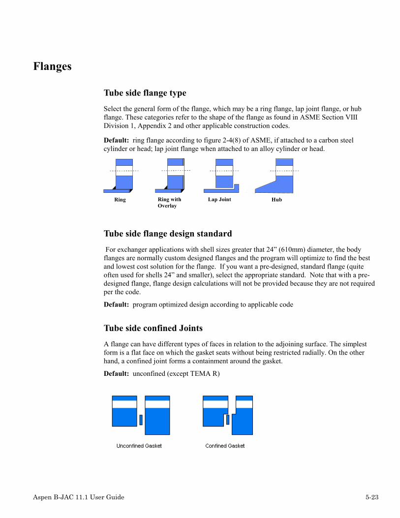
Aspen B-JAC 11.1 User Guide 5-23
Flanges
Tube side flange type
Select the general form of the flange, which may be a ring flange, lap joint flange, or hubflange. These categories refer to the shape of the flange as found in ASME Section VIIIDivision 1, Appendix 2 and other applicable construction codes.
Default: ring flange according to figure 2-4(8) of ASME, if attached to a carbon steelcylinder or head; lap joint flange when attached to an alloy cylinder or head.
Ring Ring withOverlay
Lap Joint Hub
Tube side flange design standard
For exchanger applications with shell sizes greater that 24” (610mm) diameter, the bodyflanges are normally custom designed flanges and the program will optimize to find the bestand lowest cost solution for the flange. If you want a pre-designed, standard flange (quiteoften used for shells 24” and smaller), select the appropriate standard. Note that with a pre-designed flange, flange design calculations will not be provided because they are not requiredper the code.
Default: program optimized design according to applicable code
Tube side confined Joints
A flange can have different types of faces in relation to the adjoining surface. The simplestform is a flat face on which the gasket seats without being restricted radially. On the otherhand, a confined joint forms a containment around the gasket.
Default: unconfined (except TEMA R)

5-24 Aspen B-JAC 11.1 User Guide
Shell side flange type
Specify the general form of the flange, which may be a ring flange, lap joint flange, or hubflange. These categories refer to the shape of the flange as found in ASME Section VIIIDivision 1, Appendix 2 or other applicable construction codes.
Default: ring flange according to figure 2-4(8) of ASME, if attached to a carbon steelcylinder or head; lap joint flange when attached to an alloy cylinder or head.
Ring Ring withOverlay
Lap Joint Hub
Shell side flange design standard
For exchanger applications with shell sizes greater that 24” (610mm) diameter, the bodyflanges are normally custom designed flanges and the program will optimize to find the bestand lowest cost solution for the flange. If you want a pre-designed, standard flange (quiteoften used for shells 24” and smaller), select the appropriate standard. Note that with a pre-designed flange, flange design calculations will not be provided because they are not requiredper the code.
Default: program optimized design according to applicable code
Shell side confined joints
A flange can have different types of faces in relation to the adjoining surface. The simplestform is a flat face on which the gasket seats without being restricted radially. On the otherhand, a confined joint forms a containment around the gasket.
Default: unconfined (except TEMA R)
Individual standards
To modify a specific flange provide the following as applicable: design standard, code type,standard type, standard rating, code facing, standard facing, and confined joint.

Aspen B-JAC 11.1 User Guide 5-25
Special flange types per ASME Fig. 2.4
These selections are available under the code type pull-down menu.
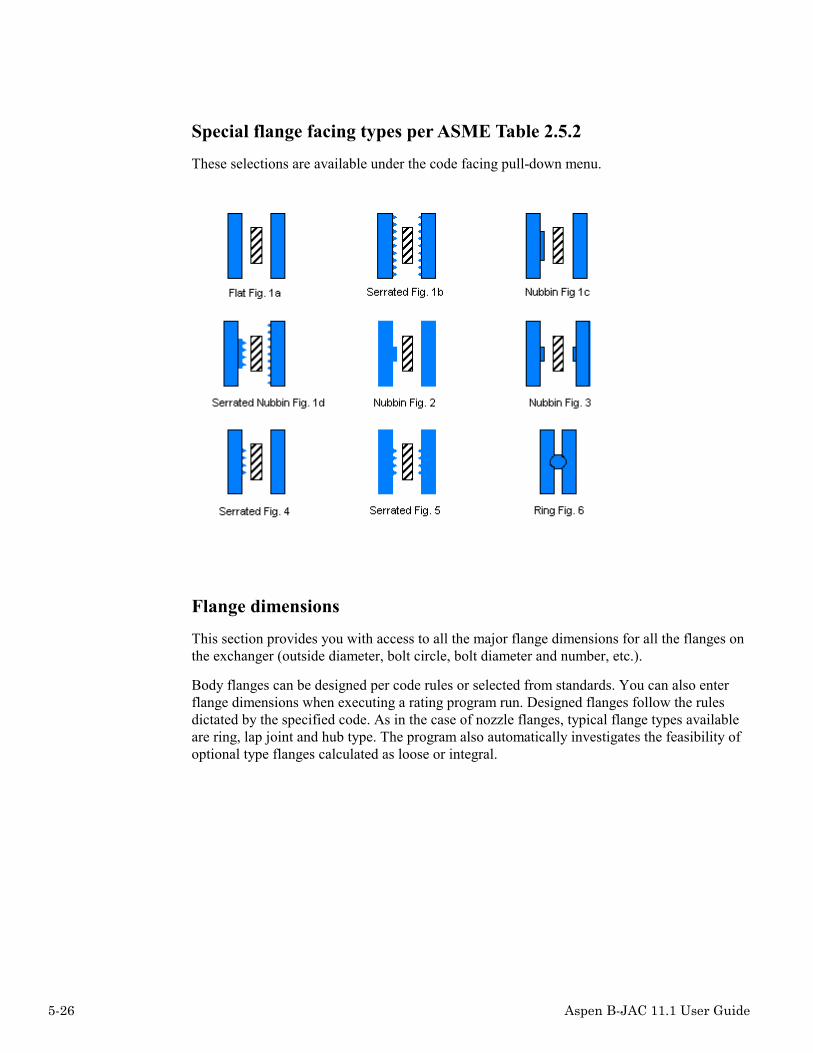
5-26 Aspen B-JAC 11.1 User Guide
Special flange facing types per ASME Table 2.5.2
These selections are available under the code facing pull-down menu.
Flange dimensions
This section provides you with access to all the major flange dimensions for all the flanges onthe exchanger (outside diameter, bolt circle, bolt diameter and number, etc.).
Body flanges can be designed per code rules or selected from standards. You can also enterflange dimensions when executing a rating program run. Designed flanges follow the rulesdictated by the specified code. As in the case of nozzle flanges, typical flange types availableare ring, lap joint and hub type. The program also automatically investigates the feasibility ofoptional type flanges calculated as loose or integral.

Aspen B-JAC 11.1 User Guide 5-27
If check rating an existing flange provide the following information: outside diameter, insidediameter, bolt circle, thickness, gasket O.D., gasket width, gasket thickness, bolt diameter,number of bolts, hub length, hub slope, and weld height (if applicable).
Flange nubbin/recess/gasket
If check rating an existing flange provide the following information: nubbin width, nubbinheight, nubbin diameter, recess depth, recess diameter, overlay thickness, gasket m factor, andgasket seating stress when applicable.
Design temperature for flanges
You can set specific design temperatures for the body flanges in lieu of the global designtemperatures.

5-28 Aspen B-JAC 11.1 User Guide
Included gasket rib area for gasket seating
The program will adjust the flange design to include the rib seating area of the gasket. Thisassures that the flange will be able to keep the gasket sealed for operating conditions. Youmay omit the gasket seating area for the pass partition ribs for the flange calculations.
Default: include the pass partitions rib area
Type of bolt
You can set the bolt type, US or Metric or Din.
Default: type applicable to the code and standards specified
Body flange full bolt load
Per Note 2 of ASME Section VIII, paragraph 2-5(e), if additional safety is needed againstabuse or where is it is necessary to withstand the full available bolt load, AbSa, specify, Yes,for this full bolt load to be considered.
Default: Standard bolt load, (Am+Ab) * Sa / 2
Design to satisfy flange rigidity rules
Specify, Yes, to have the program adjust the flange design as required to flange rigidity rules.
Default: No – flange will not be adjusted for rigidity rules.
Pressure vessel flange locations
Indicate the locations where you want to locate body flanges on a pressure vessel tank.
Backing ring details for a S type rear head
I you are check rating an existing S type rear head, specify the dimensions for the backingring.
Default: Design a new backing ring if no dimensions are given.

Aspen B-JAC 11.1 User Guide 5-29
Tubesheet
Tube-to-tubesheet joint type – Appendix A
The type of joint used to attach the tubes into the tubesheet holes.
The simplest form is by expanding the tube wall into the holes with an expanding tool. One ortwo grooves inside the tubesheet holes are sometimes used to strengthen the attachment.
Depending on the process, users may desire to weld the tubes into the tubesheets with a sealor strength weld in addition to expanding the tube. Reference the applicable construction codefor detail requirements for strength joints (such as UW-20 of ASME Section Div.1)
A seal or strength weld can also be used without any expansion of the tubes.
Default: expanded only (2 grooves)

5-30 Aspen B-JAC 11.1 User Guide
Tubesheet extension type
When applicable, the program will evaluate the tubesheet extension against the adjoiningflange moments.
Default: extended edge for bolting depending on the type of geometry
Tubesheet type
Double tubesheets are used when it is extremely important to avoid any leakage between theshell and tube side fluids. Double tubesheets are most often used with fixed tubesheetexchangers, although they can also be used with U-tubes and outside packed floating heads.
The gap type double tubesheet has a space, usually about 150 mm (6 in.), between the inner(shell side) and outer (tube side) tubesheets. TEAMS will provide a recommended gap. Theintegral type double tubesheet is made by machining out a honeycomb pattern inside a singlethick piece of plate so that any leaking fluid can flow down through the inside of thetubesheet to a drain. This type is rare, since it requires special fabrication tools andexperience.
Default: normal single tubesheet(s)

Aspen B-JAC 11.1 User Guide 5-31
Tubesheet attachment type
The tubesheet attachment defaults to land. This is a recess behind the tubesheet on which theshell rests (typically 3/16" - 5 mm). Stub end is an extension parallel to the shell axis to whichthe shell is attached. This method normally requires machining of the stub end with inner andouter radii. See ASME VIII-1 Fig. UW-13.3(c) for example of stub end.
Default: land recess
Tube-to-TubeSheet weld type per UW-20
Specify if the tube to tubesheet welds are to be considered as strength welds per ASME.Also specify the af and ag dimensions.
Fillet weld length, af
Fillet weld leg size for the tube to tubesheet welds. Specify if the tube to tubesheet welds areto be considered as strength welds per ASME.
Groove weld length, ag
Groove weld leg for the tube to tubesheet welds. Specify if the tube to tubesheet welds are tobe considered as strength welds per ASME.
Tubesheet design method
You can select TEMA (Eight Edition), Code (Appendix AA - latest addenda), or thethicker/thinner of the two methods for the tube sheet design. The ASME Code accepts bothmethods for the tubesheet design. If no method is selected, the program will use the thickertubesheet of the two methods. Depending on the design conditions and materials ofconstruction, either method may result in a thicker tubesheet. Generally the ASME methodwill result in thicker tubesheets, especially, if the tubesheet is welded to the shell or headcylinder. Note that there is currently no ASME method to calculate a floating head tubesheet.Most users select the thinner tubesheet of the two methods to save cost.

5-32 Aspen B-JAC 11.1 User Guide
Tubesheet/Cylinder Optimization
0 = program – program will calculate the minimum required tubesheet thickness for bendingand shear. Then it will check the stresses on the tubes and cylinders (shell or channel) weldedto the tubesheet(s). If the stresses on the tubes are exceeded, the program automatically putsan expansion joint in. If the welded shell (i.e. BEM) or welded channel (i.e. NEN) isoverstressed at the junction with the tubesheet, the program will issue a warning.
1 = Increase tubesheet thickness – program will increase the tubesheet thickness until allstresses are satisfied, including adjacent components – tubes, shell, channel. This selectionresults in the thickest tubesheet(s) and thinnest cylinder thickness at the junction.
2 = Increase adjacent cylinder thickness – the program will increase the shell thickness(only a small portion adjacent to the tubesheet) and/or the channel thickness (depending ofwhich one is controlling) until the cylinder stresses at the junction with the tubesheet(s) aresatisfied. This selection results in the thinnest tubesheet(s) and thickest cylinder thickness atthe junction. As the cylinder thickness is increased, the tubesheet is reinforced by the thickercylinder welded to it and consequently the tubesheet thickness is automatically reduced.
If the User receives a warning that either the shell cylinder or channel cylinder at thetubesheet junction is overstressed, re-run the program with optimization method 2 (increaseadjacent cylinder thickness). This may take a while in some designs. If the resultingcylinder thickness adjacent to the tubesheet is acceptable, the optimization run is finished. Ifthis thickness is not acceptable (too thick), fix this thickness in input (tab Miscellaneous inthe tubesheet section) and then run selection 1 = increase tubesheet thickness. Thismethodology usually results in a tubesheet thickness less than TEMA with a somewhatthicker cylinder welded to the tubesheet.
NOTE: The program automatically adjusts all the affected components during theseoptimizations, i.e adjacent flange geometry.
Tubesheet design temperature
If provided here, the program will use these temperatures as the design temperatures for thetube sheets in lieu of the general shell/tube side design temperatures specified in the DesignSpecification section.

Aspen B-JAC 11.1 User Guide 5-33
Tubesheet dimensions
If check rating an existing exchanger, enter the following dimensional information, tubesheetOD, tubesheet thickness, width-partition groove, depth-partition groove, and if cladded; theclad diameter, clad thickness, front tubesheet clad material tube side, and rear tubesheet cladmaterial tube side.
Tubesheet cladding material
Tubesheet cladding is typically a layer of alloy material applied to a carbon steel base on thetube-side face of the tubesheet.
Tubesheet clad type
Specify how the cladding is bonded to the tubesheet base material, explosively bonded or aloose type. Note that the type of bonding does not affect Code calculations.
Corrosion allowance – shell side & tube side
You can enter specific corrosion allowance requirements for the shell side and tube side ofthe tubesheets. The values entered here will override the global corrosion allowance enteredfor the shell and tube sides in the Design Specification section. Corrosion Allowance isobtained from the TEMA standards as follows: For carbon steel TEMA C and B: 0.0625" (1.6mm). For carbon steel TEMA R: 0.125" (3.2 mm). Enter zero for no corrosion allowance.There is no default corrosion allowance for materials other than carbon steel. The user canspecify any reasonable value for corrosion allowance.
Default: TEMA requirements.
Recess dimensions
If check rating an existing exchanger, enter the following dimensional information: recessdepth at ID gasket surface, recess diameter at ID gasket surface, recess depth at OD gasketsurface, and recess diameter at OD gasket surface.

5-34 Aspen B-JAC 11.1 User Guide
Backing flange behind tubesheet
A backing flange behind the tubesheet is used to avoid transferring the flange moment causedby the adjoining flange to the tubesheet. The backing ring flange can also be made ofinexpensive steel material when the tubesheet is made of alloy.
Tubesheet tapped – rear ‘T’ type
Select here to have bolt holes tapped in rear tubesheet in lieu of bolted through the tubesheet.
Adjacent Tubesheet Data
If cylinders attached to the tubesheet are of different materials and design specifications fromthat of the general cylinders specifications, you can specify this data in this section.
Differential design pressure
If specified, the tubesheets will be designed to a differential design pressure conditionbetween the tube side and shell side of the exchanger. The normal default is to design thetubesheet applying the full tube side pressure for the first case and then the full shell sidepressure for the second case and use the greater tubesheet thickness for those two conditions.
Default: Checks both the tube side and shell side – uses greater thickness of the twoconditions.
Tube expansion depth ratio
You can specify the ratio of the tube expansion length in the tubesheet to the total length ofthe tubesheet. This will be used for the tube pull out load analysis.
Default: TEMA requirements
Load transferred form flange to tubesheet
The program will automatically transfer the calculated load from the body flange to thetubesheet for the flange extension calculations. For special design considerations, you canspecify the load to be used in these calculations.
Default: The calculated load from the body flange design per the applicable code.

Aspen B-JAC 11.1 User Guide 5-35
Tubesheet allowable stress at design temperature
If you wish to specify a special allowable design stress for the tubesheet calculations, enterthat value. If not specified, the program will use an allowable design stress per the applicablecode.
Default: Allowable design stress per the applicable design code.
Double tubesheet specifications
If double tubesheets have been selected, specify any special design requirements. If notprovided, the program will select optimum values for design.
Expansion Joints
Expansion joint for fixed tubesheet design
Specify if you want an expansion joint. The program will always check the design forexpansion joint requirements and notify you if an expansion joint is required. Program =program will check and add expansion joint if required. Yes = program will add an expansioneven if one is not required. No = unit will be designed without an expansion joint andprogram will notify you if the unit is overstressed.
Default: program will add expansion joint if required per applicable code
Expansion joint type
You can select a flanged and flued type, flanged only type, bellows type, or a self reinforcingbellows type. The flanged type is generally the lowest cost expansion joint but is not asflexible as the bellows type. Aspen Teams will default to the flanged and flued type forTEMA exchangers. If a suitable joint cannot be determined, specify the bellows type. Thedesign method for the flanged type is TEMA and for the bellows type is per the specifiedCode.
Aspen Teams will design thick-wall expansion joints per TEMA Section 5. Aspen Teams willdesign thin -wall expansion joints per ASME-VIII-1 App. 26. The flanged-and-flued typerefers to an expansion joint with two radii. The flanged-only type only has a radius at theouter edge. The joint with the shell is a straight angle.
The thin-wall expansion joint is also known as a "bellows" type. It also has an "S" shape.Typical thicknesses are less than 1/8" (3.2 mm) and made of alloy materials. Reinforcedbellows requires extra material to be placed on the outside of the joint to provide additionalrigidity.

5-36 Aspen B-JAC 11.1 User Guide
Default: flanged and flued type
Flanged and Flued Flanged only
Bellows Renforced bellows
Shell mean metal temperature
Program will use this temperature to design a fixed tubesheet and expansion joint. If notspecified, the program will use the design temperatures. The mean metal temperatures arevery important in the correct calculation of the relative expansion of tubes and shell. It isespecially important when the program defaults to the design temperatures because these maynot be realistic.
Tubes mean metal temperature
Program will use this temperature to design a fixed tubesheet and expansion joint. If notspecified, the program will use the design temperatures. The mean metal temperatures arevery important in the correct calculation of the relative expansion of tubes and shell. It isespecially important when the program defaults to the design temperatures because these maynot be realistic.
Tubesheets mean metal temperature
Provide mean metal temperature to be used in the tubesheet design calculations. Normally thetubesheet metal temperature is very close to the tube metal temperature.

Aspen B-JAC 11.1 User Guide 5-37
Expansion Joint GeometryIf an expansion joint is required specify the material. If you are check rating an existing jointprovide the following: outside diameter, outer cylinder thickness, annular plate thickness,cylinder length, straight flange length, knuckle radius, spring rate, corrosion allowance,number of joints, location of first joint, location of second joint (if required), spring rate(corroded), spring rate (new), and cycle life as applicable. Reference TEMA 1988 section 5for additional information.
Expansion joint corrosion allowance
Specify a specific corrosion allowance, which will override the global corrosion allowance.
Number of expansion joints
Specify up to two expansion joints.
Location of expansion joint one
Specify the Zone location for the first expansion joint.
Location of expansion joint two
Specify the Zone location for the second expansion joint.
Expansion joint spring rate
Specify the bellows type expansion joint spring rate for the corroded and new conditions.Program will calculate the spring rate if not specified.

5-38 Aspen B-JAC 11.1 User Guide
Expansion joint cycle life
Program will calculate the estimated cycle life or you can input a required cycle life.
Bellows type expansion joint details
If check rating an existing bellows type expansion joint, specify the details for the joint.
TEMA stress multipliers
User may specify stress multipliers to adjust the allowable design stresses used in the TEMAexpansion joint calculations. If left blank, the program will use allowable stressesrecommended by TEMA.
Tubes/Baffles
Number of tubes
If the number of tubes is not entered, the program will calculate the maximum number oftubes that will fit in a given exchanger geometry. This number will vary not only with thetube diameter, pitch and layout, but also with the type of exchanger (floating head, etc.).
Default: program calculated
Tube length
Specify the overall tube length for straight tubes. For U-tubes specify the tangent straightlength.
Tube OD
Specify the actual dimensional outside diameter.
Tube wall thickness
The program will check if the tube wall thickness is adequate to withstand the designpressure, both internal and external. If you enter the average tube wall thickness, determinethe minimum tube wall based upon the manufacturing tolerance (generally in the range of 10to 12%) and verify it is not less that the calculated required thickness for the tubes.

Aspen B-JAC 11.1 User Guide 5-39
Tube type
Plain tubes do not have any enhancing type of surface on them.
Fin tubes are classified as integral low-fin types with densities of 16 to 30 fins per inch (630to 1181 fins per meter). Typical fin heights are 0.015 to 0.040 inches (0.4 to 1 mm).
The program requires only the fin density.
Tube wall specification
Specify the tube wall specification. This wall specification will appear on the TEMA datasheet. If you have specified average wall thickness, see note above for tube wall thickness.
Default: minimum wall.
Tube projection from tubesheet
Tube projection from the tubesheet face should be based upon the type of attachment and anycustomer specification requirements.
Default: 1.5 mm or 0.625 in.
Tubes design temperature
Specify the tube design temperature, which will determine the physical properties used in thecode calculations.
Default: higher of shell and tube side design temperatures
Tubes corrosion allowance
For most design applications, no corrosion allowance is applied to the tubes even if you havespecified a general corrosion allowance for the shell and tube sides of the exchanger. Specifythe total corrosion (shell side and tube side) allowance required.
Default: zero corrosion allowance
Tubes allowable design stress at design temperature
If not provided, program will determine the design stress based upon tube material specifiedat the design temperature. You may override this calculated design stress by entering it here.
Default: allowable design stress at design temperature based upon material specified

5-40 Aspen B-JAC 11.1 User Guide
Fin Tube Data
Fin density
If you specify fin tubes as the tube type, then you must specify the desired fin density (i.e., thenumber of fins per inch or per meter depending on the system of measure). Since the possiblefin densities are very dependent on the tube material, you should be sure that the desired findensity is commercially available.
The dimensional standards for finned tubes made by Wolverine, High Performance Tube, andWieland are built into the program. If you choose one of these, the program will automaticallysupply the corresponding fin height, fin thickness, and ratio of tube outside to inside surfacearea. If you do not choose one of the standard fin densities, then you must also supply theother fin data which follows in the input.
The standard fin densities, fins/inch, for various materials are:
Carbon Steel -19
Stainless Steel-16, 28
Copper-19, 26
Copper-Nickel 90/10-16, 19, 26
Copper-Nickel 70/30-19, 26
Nickel Low Carbon Alloy 201-19
Nickel Alloy 400 (Monel)-28
Nickel Alloy 600 (Inconel)-28
Nickel Alloy 800-28
Hastelloy-30
Titanium-30
Admiralty-19, 26
Aluminum-Brass Alloy 687-19
Fin height
The fin height is the height above the root diameter of the tube.
Fin thickness
The fin thickness is the average fin thickness.

Aspen B-JAC 11.1 User Guide 5-41
Baffle type
SingleSegmental
DoubleSegmental
TripleSegmental Full Support
No Tubesin Window
Rod Strip
Baffle types can be divided up into two general categories: segmental baffles and grid baffles.Segmental baffles are pieces of plate with holes for the tubes and a segment that has been cutaway for a baffle window. Single, double, triple, no tubes in window, and disk & donut areexamples of segmental baffles. Grid baffles are made from rods or strips of metal which areassembled to provide a grid of openings through which the tubes can pass. The programcovers two types of grid baffles - rod baffles and strip baffles.
Segmental baffles are the most common type of baffle, with the single segmental bafflebeing the type used in a majority of shell and tube heat exchangers. The baffles should have atleast one row of overlap and therefore become practical for a 20 mm or 0.75 in. tube in shelldiameters of 305 mm (12 in.) or greater for double segmental and 610 (24 in.) or greater fortriple segmental baffles. (Note: the B-JAC triple segmental baffle is different than the TEMAtriple segmental baffle.)
Full supports are used in K and X type shells where baffling is not necessary to direct theshell side flow.
No tubes in window is a layout using a single segmental baffle with tubes removed in thebaffle windows. This type is used to avoid tube vibration and may be further enhanced withintermediate supports to shorten the unsupported tube span. The standard abbreviation for notubes in the window is NTIW.
Rod baffle design is based on the construction and correlations developed by PhillipsPetroleum. Rod baffles are limited to a square tube pattern. The rods are usually about 6 mm(0.25 in.) in diameter. The rods are placed between every other tube row and welded to acircular ring. There are four repeating sets where each baffle is rotated 90 degrees from theprevious baffle.
Strip baffles are normally used with a triangular tube pattern. The strips are usually about 25mm (1 in.) wide and 3 mm (0.125 in.) thick. The strips are placed between every tube row.Intersecting strips can be notched to fit together or stacked and tack welded. The strips arewelded to a circular ring. Strip baffles are also sometimes referred to as nest baffles.
Default: single segmental except X shells; full support for X shell

5-42 Aspen B-JAC 11.1 User Guide
Baffle orientation
The baffle orientation is with respect to a horizontal exchanger. On vertical units the bafflecut will be typically perpendicular to the shell nozzles axes.
Baffle cut in percent of vessel diameter
The baffle cut is based on the percent of shell diameter. Typically 15% to 45%, depending onflow parameters and type of baffle (single vs double vs triple segmental or no-tubes-in-window). For double-segmental baffles, the baffle cut is the size of the inner window dividedby the shell diameter X 100. For triple-segmental baffles, the baffle cut is the size of theinnermost window divided by the shell diameter X 100. For nests or rod baffles, there is nobaffle cut (leave blank or zero).
Baffle number
Number of transverse baffles including full supports when applicable. The number of bafflesapplies to all transverse baffles and full supports. It should include the full support(s) underthe nozzle(s) on a G, H, or J type shell. It should not include the full support at the beginningof the u-bend of a u-tube bundle.
Baffle spacing
Specify the center-to-center baffle spacing. This number and the number of baffles arecomplementary. If not entered, the program will determine the inlet and outlet baffle spacing.
Baffle inlet spacing
Specify the baffle spacing at the inlet nozzle. If not entered, the program will set based uponthe center to center spacing and outlet spacing if specified. If the outlet spacing is notspecified, the program will set the inlet and outlet spacing the same based upon available tubelength.

Aspen B-JAC 11.1 User Guide 5-43
Baffle outlet spacing
Specify the baffle spacing at the outlet nozzle. If not entered, the program will set based uponthe center to center spacing and the inlet spacing if specified. If the inlet spacing is notspecified, the program will set the inlet and outlet the spacing the same based upon availableremaining tube length.
Baffle thickness
Provide the actual thickness of the baffles.
Default: TEMA standards
Baffle diameter
Provide the actual baffle outside diameter.
Default: TEMA standards
Double/Triple baffle cuts
Refer to the Appendix section of this guide for information on double and triple segmentalbaffle cuts.

5-44 Aspen B-JAC 11.1 User Guide
Tubesheet Layout
Tube pattern
The tube pattern is the layout of the tubes in relation to the shell side crossflow direction,which is normal to the baffle cut edge.
Default: 30 degree
Tube pitch
This is the center-to-center distance between adjacent tubes within the tube pattern.
Default: minimum recommended by TEMA.
Tube passes
Specify the number of tube passes.
Tube pass layout type
Quadrant Mixed Ribbon
There are several possible ways to layout tubes for four or more passes.

Aspen B-JAC 11.1 User Guide 5-45
Quadrant:
Quadrant layout has the advantage of usually (but certainly not always) giving the highesttube count. It is the required layout for all U-tube designs of four or more passes. The tubeside nozzles must be offset from the centerline when using quadrant layout. The program willautomatically avoid quadrant layout for shells with longitudinal baffles and 6, 10, or 14passes, in order to avoid having the longitudinal baffle bisect a pass.
Mixed:
Mixed layout has the advantage of keeping the tube side nozzles on the centerline. It oftengives a tube count close to quadrant and sometimes exceeds it. The program willautomatically avoid mixed layout for shells with longitudinal baffles and 4, 8, 12, or 16passes.
Ribbon:
Ribbon layout nearly always gives a layout with fewer tubes than quadrant or mixed layout. Itis the layout the program always uses for an odd number of tube passes. The primaryadvantage of ribbon layout is the more gradual change in operating temperature of adjacenttubes from top to bottom of the tubesheet. This can be especially important when there is alarge change in temperature on the tube side that might cause significant thermal stresses inmixed and especially quadrant layouts.
Default: program will optimize
Impingement protection
O n B u n d le In D o m e
The purpose of impingement protection is to protect the tubes directly under the inlet nozzleby deflecting the bullet shaped flow of high velocity fluids or the force of entrained droplets.TEMA recommends that inlet impingement protection be installed under the followingconditions:• when the rho*V² through the inlet nozzle exceeds 2232 kg/(m*s²) or 1500 lb/(ft*s²) for
non-corrosive, non-abrasive, single phase fluids• when the rho*V² through the inlet nozzle exceeds 744 kg/(m*s²) or• 500 lb/(ft*s²) for corrosive or abrasive liquids

5-46 Aspen B-JAC 11.1 User Guide
• when there is a nominally saturated vapor• when there is a corrosive gas• when there is two phase flow at the inlet
If you choose a plate on the bundle the program will automatically remove tubes under theinlet nozzle so that the shell entrance area equals the cross-sectional area of the nozzle. This isapproximately equal to removing any tubes within a distance of 1/4 the nozzle diameter underthe center of the nozzle. The program uses a circular impingement plate equal in diameter tothe inside diameter of the nozzle, and approximately 3mm or 1/8in. thick.
An alternative is to put a plate in a nozzle dome, which means suspending the impingementplate in an enlarged nozzle neck, which may be a dome or a cone.
Outer tube limit diameter (OTL)
The outer tube limit (OTL) is the diameter of the circle beyond which no portion of a tubewill be placed. You can input an OTL and the program will determine the maximum numberof tubes, which will fit. If no OTL is specified, the program will calculate the OTL basedupon the inputted shell diameter and TEMA standard bundle clearances.
Default: program will calculate
Tube Layout Option
You can select to have the Teams program generate a new tube layout every time the programruns or you can select to use an existing layout. For the second option, you must first runTeams to establish a layout and then select the option to use the existing layout for allsubsequent runs.
Default: create a new layout
Max deviation per pass in percent
The program defaults to 5% maximum deviation per pass when calculating how many tubescan fit in a given pass.
Degree of symmetry
If specified, the program will attempt to put the same number of tubes per pass. If notspecified, the program will optimize as many tubes as possible in a given configuration.
Min U-bend Diameter
The program default is 3 times the tube OD.

Aspen B-JAC 11.1 User Guide 5-47
Pass Partitions
You can specify the following detailed information about the pass partitions: pass partitionlane clearance, allowable pressure drop across partition plate, front (top) pass partition platethickness, front Head Pass Partition rib length, front head pass partition rib width, passpartition dimension ‘a’, and pass partition dimension ‘b’ (Reference TEMA standards).
Open Distance
You can specify the amount of open space in the tube pattern by the percent of the shelldiameter open down from top, percent open up from bottom, and percent open in from sidesor you can specify the dimensional distance down from top, distance up from bottom ordistance in from sides.
Impingement plate diameter
The program will use this input to determine the position and the dimension of theimpingement plate This input is not required if you have already specified the shell inletnozzle OD. The default is the shell inlet nozzle O.D.
Impingement plate length and width
You can specify a rectangular impingement plate size. The default is the shell inlet nozzleO.D. for length and width (square plate).
Impingement plate thickness
This input is required if you specify there is an impingement field. You can specify anythickness for the impingement plate. The default is 3 mm or 0.125 inch.
Impingement distance from shell ID
You can specify the distance from the shell inside diameter to the impingement plate. Thedefault is the top row of tubes.
Impingement clearance to tube edge
You can specify the distance from the impingement plate to the first row of tubes.
Impingement plate perforation area %
If you are using a perforated type impingement plate, you can specify the percent of area thatthe plate is perforated.

5-48 Aspen B-JAC 11.1 User Guide
Tie Rods
You can specify the following tie rod information: tie rod number, tie rod diameter, length oftie rod, and tie rod material.
Spacers
You can specify the following for the tie rod spacers: number of spacers, diameter, spacerthickness, and spacer material.
Tube Layout Drawing
Once you have run the Teams program and have mechanical design results, you caninteractively make modifications to the tube layout.
Tubes: Tubes can be removed from the layout by clicking on the tube to be removed (tubewill be highlighted in red) and then selecting the red X in the menu. If you want to designatea tube as a plugged tube or as a dummy tube, click on the tube (tube will be highlighted inred) and then select the plugged tube icon or dummy tube icon from the menu.
Tie Rods: To remove a tie rod, click on the tie rod (tie rod will be highlighted in red) andthen select the red X in the menu. To add a tie rod, select the add a tie rod icon in the menuand then specify the location for the tie rod.
Sealing Strips: To remove a sealing strip, click on the sealing strip (sealing strip will behighlighted in red) and then select the red X in the menu. To add a sealing strip, select theadd a sealing strip icon in the menu and then specify the location for the sealing strip. Onceyou have completed your changes to the tube layout, you may want to elect to fix the layoutfor subsequent Teams runs by selecting the "Use existing layout" option located on theTubsheet Layout tab.
Nozzles General
Shell side/Tube side nozzles global settings
Flange design standard – ANSI, ISO or DIN standards can be referenced. Also anoptimized, program calculated, may be selected.
Elevation – Provide nozzle elevation from vessel centerline to face of nozzle.
Couplings – Select number of couplings to be provide in each nozzle. Program default isTEMA standards.
Flange rating – Select flange rating. Program default is to select a flange rating inaccordance with the applicable specified code.

Aspen B-JAC 11.1 User Guide 5-49
Flange type – Select nozzle flange type from list. Default is slip on type.
Flange type for code calculated flange – Select a flange type for the optimized nozzleflange.
Nozzle flange facing – Select raised or flat face type. Default is flat face.
Nozzle flange facing for code calculated flange – select facing type for a calculated nozzleflange. Default is a flat facing.
Nozzles/Couplings
Name – Provide identification for each nozzle for the drawings and text output. Programdefault starts with the letter A through J.
Description- You can provide a description for each nozzle that will appear in the text output.
Function – Specify function of nozzle, such as inlet, outlet, vent, drain . . . . Note that byidentifying the inlet nozzles the program locates impingement plates if one has been specified.
Type – For couplings only, provide coupling design rating.
Diameter – Provide nominal diameter of nozzle. If actual diameters are specified, theprogram will select the closest standard nozzle diameter per the applicable code. Program willdetermine actual diameter from the application pipe standards.
Location – Provide a zone location for the nozzle or coupling. This is an approximatelocation from which the program will calculate the actual dimensional location. Specify ageneral zone location for the nozzle, zones 1 and 2 for front head nozzles, zones 3 through 7for shell nozzles, and zones 8 and 9 for rear head nozzles. Nozzles should be located inaccordance with the TEMA type of shell that you have selected. Note that the zone locationsspecified will override standard TEMA locations.
Angle – Specify the angle location. Nozzle located at the 45 degree points, i.e. 0, 45, 90, 135…., will be oriented radially to the cylinder. All other angles will result in the nozzle belocated hill side on the cylinder.
Domes/Distributor Belts
For the Teams design mode, the program will calculate (or use defaults) for the followingdome/distributor information if the input field indicates "program" or a default is shown. Ifyou are running in the check rating mode, specify as applicable the information required.
Dome type - Type of dome: ellipsoidal, torispherical, conical, or distributor belt. Default:ellipsoidal
Dome diameter - Specify the outside diameter of the dome cylinder.
Dome location - Specify the zone location for the dome at the same location as the locationfor the attaching nozzle.

5-50 Aspen B-JAC 11.1 User Guide
Dome angle - Specify the angle for the dome as the same for the attaching nozzle.
Dome thickness - The thickness for the dome. Default: program calculated
Dome cylinder thickness - Specify the thickness for the cylinder attached to the dome.Default: program calculated
Dome attachment type – Specify the weld attachment type to vessel. Default: programselected
Reinforcing pad – If pad is to be provided, specify the OD and thickness. Default: added byprogram if required
Weld leg – Weld size for the dome to vessel attachment weld. Default: program calculated
Distributor belt type – Select type from ASME appendix 9.
Knuckle radius – Knuckle radius for flanged and flued type distributor belt. Default:program selected
Nozzle DetailsFor the Teams design mode, the program will calculate (or use defaults) for the followingnozzle detail information. If you are running in the check rating mode, specify as applicablethe following information.
Nozzle cylinders and reinforcing pad details - You can specify the following ratinginformation about the nozzles: nozzle cylinder thickness, nozzle reinforcing pad OD, nozzlereinforcing pad thickness, and nozzle reinforcing pad parallel limit.
Nozzle type attachment - Specify the type of nozzle attachment to the vessel.
Nozzle weld leg height, external projection - Specify the weld leg height at the nozzleattachment to the cylinder at the outside surface.
Nozzle weld leg height, internal projection- Specify the weld leg height of the nozzleattachment to the vessel cylinder at the nozzle projection into the vessel.
Nozzle weld leg height re-pad - Specify the weld leg height at the reinforcement pad.
Nozzle projection - Specify the projection of the nozzle into the vessel from the insidesurface. The program default is having the nozzles flush with the inside vessel surface.
Nozzle elevation - Specify the distance the nozzle extends beyond the vessel OD. Theelevation above the vessel wall defaults to a minimum of 6" (152 mm). The user can entervalues to clear the thickness of insulation, if present.
Nozzle distance from nozzle centerline gasket - Specify the distance from nozzle center lineto from tubesheet gasket face.

Aspen B-JAC 11.1 User Guide 5-51
Nozzle distance from nozzle centerline head - Specify the distance from nozzle center lineto centerline of front head nozzles.
Nozzle flange standard - The nozzle flanges can be designed or selected from standards.
Nozzle flange type - The nozzle flange types in ASME follow the ANSI B16.5 standardincluding long weld neck types (thicker necks). If you do not want separate reinforcing plates,self-reinforced nozzle styles 'H' and 'S' are also available. Style 'S' provides a thicker neck atthe junction to the vessel than style 'H' which also provides a thicker neck than a long weldneck.
Nozzle flange rating – You may input a flange rating or allow the program will determine theappropriate rating based on materials of construction and the design pressure and temperatureof the flanges per applicable standards (ANSI, DIN, or AFNOR).
Default: program determines per applicable standards
Nozzle face – Select nozzle facing type.
Default: flat face
Nozzle clearances - Specify minimum clearances for nozzles to flanges and tubesheets.
Default: one nozzle diameter

5-52 Aspen B-JAC 11.1 User Guide
Horizontal Supports
Support type
Saddles Stacked unitson saddles
The program analyzes the shell stresses caused by supports in both the horizontal (saddles).For saddles the program uses the method developed by L.P.Zick. When this method indicatesan over-stressed condition, the program will warn the user. Typical locations and angle forsaddles are 4 and 6 and 180 degrees. Other angles are only used for stacked exchangers (zerodegrees). Calculation methods for supports for stacked exchangers are not yet available.
Saddle support A location - Specify general zone (zones 3 or 4) location for the front saddlesupport.
Saddle support B location - Specify general zone (zones 6 or 7) location for the rear saddlesupport.
Saddle support location angle - Specify angle location for the saddle supports (180 degreesfor bottom supports or 0 degrees for top support with stacked units).
Distance from face of front tubesheet to bolt hole in support A - You can specify theactual dimensional location of the front support from the front tubesheet.
Distance from face of front tubesheet to bolt hole in support B - You can specify theactual dimensional location of the rear support from the front tubesheet
Load on Saddles - You can specify dead weight loads for the Saddle ‘A’ and Saddle ‘B’supports. Program will use these values in lieu of the calculated loads based upon the fullweight of the vessel.

Aspen B-JAC 11.1 User Guide 5-53
Saddle Details
You can input your own design for the saddle supports by inputting the followinginformation:
t
w
d
c e
c c
lh
d h
Saddle to shell angle of contact: Normally set at 120 degrees
Support elevation: Projection of the saddle support from the vessel centerline
Wear plate thickness: Program defaults to no wear plate. Plate thickness varies from 0.25inches up to the thickness of the shell cylinder
Base plate thickness: Normal thickness ranges from 0.5 inches to 2 inches thick.
Base plate width: Any width is accepted up to the diameter of the shell.
Base plate depth: Normal depth is from 4 inches up to 12 inches.
Gusset thickness: Gusset thickness ranges from 0.375 inch to 1 inch.
Gusset number per support: Ranges from one to four gussets
Gusset direction: Supports opened towards the center of the vessel or outward towards theends of the vessel.
Bolt holes diameter: Size ranges from 0.625 inch to 3 inch allowing for 1/8 inch clearanceto bolt diameter.
Bolt distance edge to x axis: Allow a minimum of 2 times the bolt hole size.
Bolt center to center distance: Any dimension less than the diameter of the vessel.
Bolt slot length: Generally the slot is 2 times the bolt hole diameter
Bolt quantity: Normal ranges from 2 to 8 bolts

5-54 Aspen B-JAC 11.1 User Guide
Stacked Units
You can specify the number of stacked exchangers, up to four units. A sketch showing thestacking arrangement for the exchangers will be provided. User will need to evaluate thevessel support design for base and intermediate supports. Note that it is possible to input atotal weight for the stacked exchangers and the program will design the base support usingthis total weight. The program will use the base support design also for the intermediatesupports.
Vertical SupportsCurrently the program provides a design for vertical lug type supports. The program analyzesthe shell stresses caused by vertical (lugs) positions. For vertical lug supports the programwill calculate the required lug weld height to avoid over-stressing the shell. Calculationsmethods for (3) vertical ring supports are not yet available.
Lug Type Ring Type
Vertical Support type - Specify type of vertical vessel support type. From two to four lugtype supports can be specified. The vertical ring type is a single continuous ring around theshell. Calculations for the ring type are not yet available.
Vertical Support location - Specify general zone location (zones 3 through 7) for thesupport.
Vertical Support angle - Specify angle location for the lug type supports (180 degrees apartfor two lugs and ever 45 degrees for 4 lugs).

Aspen B-JAC 11.1 User Guide 5-55
Vertical Support Details
You can input your own design for the saddle supports by inputting the followinginformation:
Wear plate thickness: Program defaults to no wear plate. Plate thickness varies from 0.25inches up to the thickness of the shell cylinder
Base plate thickness: Normal thickness ranges from 0.5 inches to 2 inches thick.
Base plate width: Any width is accepted up to the diameter of the shell.
Base plate depth: Normal depth is from 4 inches up to 12 inches.
Gusset thickness: Gusset thickness ranges from 0.375 inch to 1 inch.
Gusset number per support: Ranges from one to four gussets
Bolt holes diameter: Size ranges from 0.625 inch to 3 inch allowing for 1/8 inch clearanceto bolt diameter.
Bolt distance edge to x axis: Allow a minimum of 2 times the bolt hole size.
Bolt center to center distance: Any dimension less than the diameter of the vessel.
Bolt quantity: Normal ranges from 2 to 8 bolts

5-56 Aspen B-JAC 11.1 User Guide
Lift LugsLifting Lugs type - Lug type is plate type.
Number to lift the whole unit - Specify number of unit lifting lugs required.
Location and Angle of each Lug - Specify the zone location and angle for each lug.
Lifting Lugs Material - Specify material for lug.
Lifting Lugs Re-pad material - Specify the reinforcement pad material.
Lug Geometry
‘t’ thickness: The thickness of the lug
‘I’ Weld length: The length of the attachment weld to the vessel
‘h’ Weld size: Weld height of the attachment weld
‘H’ Distance: Height from vessel wall to centerline of hole
‘R’ Radius: Radius of lug at top
‘r’ Radius of hole: Radius of lug hole
‘p’ Re-pad thickness: Thickness of reinforcement pad
‘L’ Re-pad length: Length of reinforcement pad
‘W’ Re-pad length: Width of reinforcement pad
rR
H
lL
p
h
t W

Aspen B-JAC 11.1 User Guide 5-57
MaterialsThe Design Data Section is subdivided into two sections:• Main Materials• Nozzle Materials
Main Materials
Material Specifications
Specify materials for required components. You can use the generic material types such as"carbon steel" which the program will assign actual default material specifications dependingon the product form. For carbon steel plate, a material specification of SA-516-70 will beused for an ASME design. Appropriate specifications will be selected for other designconstruction codes. The default materials can be changed using the utility DefMats. Referencethe Appendix for a complete list of generic materials.
Default: carbon steel.
To search for a specific material specification, select the Search Databank button. Type thefirst few characters to search for a material in the databank.

5-58 Aspen B-JAC 11.1 User Guide
Normalized Materials
You can specify all carbon steel materials to be normalized per Fig. UCS-66.
Nozzle Materials
Nozzle Materials for global settings
Specify nozzle materials for required components. You can use the generic material typessuch as "carbon steel" which the program will assign an actual default material specificationsdepending on the product form. For carbon steel pipe material, a material specification of SA-106-B will be used for an ASME design. Appropriate specifications will be selected for otherdesign construction codes. The default materials can be changed using the utility DefMats.Reference the Appendix for a complete list of generic materials.
Default: carbon steel
Shell Side & Tube Side
Specify materials for the following shell side and tube side nozzle components:• Nozzle cylinder material• Nozzle flange material• Nozzle flange bolt material• Nozzle flange gasket material
Nozzle Material Individual Nozzles
You can specify materials for specific nozzles. If not specified, TEAMS will set the materialsto the default carbon steel. These will override global settings. You can use the genericmaterial types such as "carbon steel" which the program will assign actual default materialspecifications depending on the product form. For carbon steel pipe, a material specificationof SA-106-B will be used for an ASME design. Appropriate specifications will be selected forother design construction codes. The default materials can be changed using the utilityDefMats. Reference the Appendix for a complete list of generic materials.
Specify information for the following nozzle components for the specific applicable nozzle.Nominal pipe size for the Diameter, and generic or actual material specification for theCylinder Material, Nozzle Reinforcing Pad Material, Flange, Gasket, and Bolting.

Aspen B-JAC 11.1 User Guide 5-59
Program OptionsThe Program Options Section is subdivided into three sections:• Loads External- Wind and Seismic• Change Codes• Drawings.
Wind/Seismic/External Loads
External Loads
You can specify the external nozzle attachments loads and they will be analyzed per theWelding Research Council Bulletin, WRC-107. If the nozzle loads are not known but youneed the allowable loads based upon your final design, select the Heat Exchange Institute,HEI, method for external nozzle loads and the allowable loads will be calculated.
Wind Loads
Wind loads analyzed per ANSI/ASCE 7-95
Default: 160 km/hr (100 mph) wind load
Seismic Loads
Seismic load evaluated per ANSI/ASCE 7-95.
Default: zone 1
Change CodesThe last screen of the long form input allows you to specify change codes with the associatedvalues.
The format for change code entries is: CODE=value
Change codes are processed after all of the other input and override any previously set value.For instance, if you specify the tube outside diameter as 20 mm in the regular input screens,then enter the change code TODX=25, the 25 will override the 20. If you enter the samechange code more than once, the last value will prevail.
Another good use of the change code screen is to "chain" to another file containing onlychange codes. This is especially convenient if you have a line of standard designs, which you

5-60 Aspen B-JAC 11.1 User Guide
want to use after you have found a similar solution in design mode. This can be done by usingthe FILE= change code, followed by the name of the file containing the other change codes.The other file must also have a .BJI filetype. You can create this change code file with astandard edit program. For example, the entry FILE=S-610-2 would point to a file named S-610-2.BJI, which might contain the following data:
SODX=610,TLNG=5000,TNUM=458,TPAS=2,BSPA=690,TODX=20,TPAT=1
The following pages list the change codes that are available in the Aspen TEAMS program.
Change Codes – General
bttk= baffle thickness
cfac= "C" factor in calculation of flat covers
coan= conical head angle (must be less than or equal to 30 degrees)
code= code requirement: 1=ASME 2=CODAP 3=AD/DIN
elra= radius of turn for 90 degree elbow
fcgw= front head cylinder girth butt welds present 0=no 1=yes
fhct= front head flat removable cover thickness
file= specify the name of a file which contains change codes
jess= joint efficiency for shell side cylinders for nozzle repad calcs.
jets= joint efficiency for tube side cylinders for nozzle repad calcs.
lang= language for input and output
1=English 2=French 3=Spanish 4=German 5=Italian
meas= system of measure: 1=U.S. 2=SI 3=metric
nodr= no drawings in TEAMS summary output 0,1=yes 2=no
otlm= outer tube limit
rblf/rblr= total length of pass partition ribs in front/rear head
srmt/stf1= stiffening ring material / number of stiffening rings
rbwf= effective width of pass partition ribs in front head
rbwr= effective width of pass partition ribs in rear head
rcgw= rear head cylinder girth butt welds present: 0=no 1=yes
rhct= rear head flat removable cover thickness
scgw= shell cover cylinder girth butt welds present 0=no 1=yes

Aspen B-JAC 11.1 User Guide 5-61
scat= CODAP construction category shell side: 1=A 2=B 3=C 4=D
shgw= shell girth butt welds present: 0=no 1=yes
shje= shell joint efficiency (ASME)
sjef= CODAP joint efficiency on shell side (0.85 or 1)
sstp= shell side test pressure
ssto= shell side tolerance for plate
suts= tubesheet considered supported: 0=program 1=yes 2=no
tcat= CODAP construction category tube side: 1=A 2=B 3=C 4=D
tjef= CODAP joint efficiency on tube side (0.85 or 1)
tkmn= determines if input thickness of pipe is: 0=nominal 1=minimum
tsto= tube side tolerance for plate
tstp= tube side test pressure
tupr= distance tubes project from tubesheet
weir= option to eliminate weir in kettle (-1=no weir)
heat= carbon steel material normalized/tempered 0=no 1=yes

5-62 Aspen B-JAC 11.1 User Guide
Change Codes - Cylinders & CoversFront Head Rear Head
cover cyl cover cyl
thickness fcot= fcyt= rcot= rcyt=
outside diameter fcod= fcyd= rcyd= rcod=
length (+) fcyl= rcyl=
ext.press.length eln2= eln3=
ellip head ratio fcer= rcer=
toris head dish r.* fcdr= rcdr=
toris head k. rad.* fckr= rckr=
over "hub" length fhlg= rhlg=
Shell Shell Cover
cyl cyl cover
thickness shth= scyt= scot=
outside diameter scyd= sccd= scod=
length (+) scyl= sccl=
ext.press.length (&) eln2= eln4=
ellip head ratio scer=
toris head dish r.* scdr=
toris head k. rad.* sckr=
cover "hub" length sclg=
(+)=flange/ts face-to-face or weld
*=in percent of head diameter.
(&)=eln1 and stf1 should be issued together stf1=number of stiff.rings
Eccentric Kettle Vapor Distr Belt A Distr Belt B
Redcr Cyl Belt Cyl Ann.Ring
Cyl Ann.Ring
thickness erth= keth= vbth= — — — —
outsidedia
— keod= vbod= — — — —
material ermt= kemt= — — — — —
id/length — keid/kcyl — — — — —

Aspen B-JAC 11.1 User Guide 5-63
Change Codes - NozzlesNozzle Nozzle Dome
Cyl Reinf Pad Redcr Cyl Reinf Pad
thickness nzta-j zrta-j nnta-j ncta-j nrta-j
outside dia — zrda-j — — nrda-j
parallel limit — nzpa-j — — —
nzxa thru nzxj= distance nozzle extends beyond inner surface of vessel
fnfa thru fnfj= BJAC facing type for nozzle flange (ASME 2-5-2) (value=1 to 9)
wnfa thru wnfj= width of nubbin for nozzle flange (ASME table 2-5-2)
nwld= increase nozzle to vessel weld leg to eliminate pad: 0=yes 1=no
nplm= percent parallel limit for shell nozzle adjacent to tubesheet (0=100%)
nfct= clearance between tube nozzle flange and back side of flange (0=0.5")
nrtp= provide 100% metal replacement in pad: 0=no 1=uncorroded 2=corroded
rpmt= minimum reinforcing pad thickness
nrcl= clearance between reinf. pad weld and back of flange/tubesheet (0=2")
nccl= clearance between nozzle cyl. weld and back of flange/tubesheet (0=2")
nfcs= clearance between shell nozzle flange & front side of tubesheet (0=0.5")

5-64 Aspen B-JAC 11.1 User Guide
Change Codes – Body Flanges
---Front Head-- ----Rear Head----
Cover at TbSh at TbSh Cover
thickness ffct= fftt= rftt= rfct=
min bolt dia fcmb= ftmb=
rtmb= rcmb=
facing type fbfa= fbfb= fbff= fbfg=
nubbin width wbfa= wbfb= wbff= wbfg=
confined joint(**) fccj= ftcj= rtcj= rccj=
gasket width gawa= gawb=
gawf= gawg=
weld height fwla= fwlb= fwlf= fwlg=
Shell Shell Shell
Front Rear Cover
thickness fsft= rsft= scft=
min bolt dia — — scmb=
facing type fbfc= fbfd fbfe=
nubbin width wbfc= wbfd= wbfe=
confined joint(**) fscj= —- sccj=
gasket width gawc= gawd= gawe=
weld height fwlc= fwld= fwle=
**=(0=no 1=yes)
fbft= front backing ring flange thickness
rbft= rear backing ring flange thickness
bolt= bolt type: 1=u.s. 2=metric
shnk= DIN bolt type: 1=waisted-shank 2=rigid
sfdt= design temperature for shell side body flanges and bolting
tfdt= design temperature for tube side body flanges and bolting

Aspen B-JAC 11.1 User Guide 5-65
Change Codes - Floating Head Flangefhft= floating head - flange thickness (recess not included)
fhid= floating head - flange inside diameter
fhdi= floating head - dish inside crown radius
fhdt= floating head - dish (or head) thickness
fhhr= floating head - dish lever arm(+ toward tube side/- toward shell side)
fhmb= floating head - minimum bolt outside diameter
fhbf= floating head - backing ring flange thickness (recess not included)
cifh= floating head - corrosion on the shell side of floating cover
fhtd= floating head - design temperature
rtcj= confined joint for rear head gasket at tubesheet: 0=no 1=yes
fhnu= bjac facing type for inside flt. head flange (ASME 2-5-2) (value=1 to 9)
fhwi= width of nubbin for inside float. head flange (ASME table 2-5-2)
FHFL or BFLF = floating head - flange rating (FHFL or BFLF=1 for rating)
BRRE= IFH "S" type backing ring recess: 0=program 1=none 2=std. 3=angled

5-66 Aspen B-JAC 11.1 User Guide
Change Codes - Tubesheets & Expansion Jointconv= number of convolutions
cycl= minimum expansion joint cycle life (TEMA default=2000 cycles)
diff= differential design pressure (0=no, 1=yes)
difp= actual diff. pressure
ejbe= bellows 1=unreinforced 2=reinforced
ejca= expansion joint corrosion all.
ejfa= expansion joint straight flange - inner cylinder (TEMA fig. rcb-8.21) **
ejfb= expansion joint straight flange - outer cylinder (TEMA fig. rcb-8.21) **
ejod= expansion joint outside diameter
ejra= expansion joint knuckle radius at inside junction (TEMA fig. rcb-8.21)
ejrb= expansion joint knuckle radius at outside junction (TEMA fig. rcb-8.21)
ejrm= bellows reinforcement material
ejth= expansion joint thickness (TEMA "te" fig. rcb-8.21)
ejtp= expansion joint type: 91=f*f 92=flanged only 93=bellows
ejwi= expansion joint width (TEMA 2*"lo" fig. rcb-8.21) **
ftsa= fixed tubesheet attachment: 1=backing strip 2=land 3=stub
ftsc= front tubesheet clad thickness
** = if -1 is entered, value will be zero in calculations.
ftst= front tubesheet thickness
octh= expansion joint outer cylinder thickness (TEMA "to" fig. RCB-8.21)
rtsc= rear tubesheet clad thickness
rtst= rear tubesheet thickness
tsco= fixed tubesheet standard selection: 0=program 1=ASME 2=TEMA
xjsr= expansion joint spring rate - new
xsrc= expansion joint spring rate - corroded
** = if -1 is entered, value will be zero in calculations.

Aspen B-JAC 11.1 User Guide 5-67
Change Codes - Supportsangc= saddle-to-shell angle of contact (100 to 170 deg) increasing angc will reduce all stresses except bending at midspan
satw= saddle transverse width - reciprocal of angc above
stda= distance from face of front tubesheet to first saddle (a)
stdb= distance from face of front tubesheet to second saddle (b) placing saddle closer to respective tubesheet will decrease bending stress at saddle but increase both bending at midspan and shell tangential shear (unstiffened by head or flange/tubesheet)
salw= saddle longitudinal width
wptk= wear plate thickness (saddles and lugs) -1 = no plate increasing both salw or wptk will reduce both circumferential stress at horn of saddle and ring compression over saddle. if the saddle is located further than a/r=0.5 the vessel thk. Will not include the wear plate in the calculation of the circum.stress.
lugt= vertical lug thickness (base plate and gussets)
lugh= vertical lug height
Change Codes - Dimensionsnzel= elevation of nozzles from the centerline of the vessel
nzla thru nzlj= nozzle elevation from the centerline of the vessel
stla thru stld= support elevation from centerline of vessel
nzda thru nzdj= distance of nozzle center from front face of front tubesheet
xjda thru xjdc= distance of expansion joint from front face of front tubesheet
stda thru stdd= distance of support from front face of front tubesheet
cpda thru cpdj= distance of coupling from front face of front tubesheet
rfpt = drawing reference point. 0,1=face of front TS 2=centerline front head nozzle.
Drawings
User can select which drawing to be generated when the program runs. Drawing numbers canalso be specified.

5-68 Aspen B-JAC 11.1 User Guide
ResultsThe Results Section is divided into six sections:• Input Summary• Design Summary• Vessel Dimensions• Price• Drawings• Code Calculations
Input SummaryThe Input Summary Section is subdivided into three sections:• Basic Data/ Fittings/Flanges• Cylinders/Covers/TubeSheets• Materials/Lift Lugs/Partitions
Basic Data/Fittings/Flanges
This part of the input file summary includes information on:• Description/Codes and Standards• Design Specifications• Geometry• Tubesheet/Tubes• Baffles/Tube Layout• Supports -Horizontal/Vertical• Nozzles• Nozzle Cyl/Re-pads• Flanges• Flange Misc.

Aspen B-JAC 11.1 User Guide 5-69
Cylinders/Covers/Tubesheets Details
This part of the input file summary provides the detailed input information on:• Cylinders• Front Head Details• Rear Head Details• Front Head Cover• Front Head Cover Details• Rear Head Cover• Rear Head Cover Details• Shell Cylinder• Tubesheets Details• Expansion Joint Details• Shell Cover
Materials/Lift Lugs/Partitions
This part of the input file summary includes information on:• Main Materials• Nozzle Global Materials• Nozzle Specific Materials• Domes/Coupling Materials• Lift Lug Details• Pass Partitions• Tie Rods and Spacers• Nozzle Clearances
Design SummaryThe Design Summary Section is subdivided into five sections:• Warnings & Messages• Design Specifications/Materials• MDMT/MAWP/Test Pressure• Overall Dimensions/Fitting Locations• Wind and Seismic Loads
Warnings & Messages
Teams provides an extensive system of warnings and messages to help the designer of heatexchanger design. Messages are divided into five types. There are several hundred messagesbuilt into the Aspen Hetran program. Those messages requiring further explanation aredescribed here.

5-70 Aspen B-JAC 11.1 User Guide
Warning Messages
These are conditions which may be problems, however the program will continue.
Error Messages
Conditions which do not allow the program to continue.
Limit Messages
Conditions which go beyond the scope of the program.
Notes
Special conditions which you should be aware of.
Suggestions
Recommendations on how to improve the design.
Design Specifications/Materials
Design Specifications
This is intended to be a concise summary of the design requirements, including calculateddesign information such as weights and nozzle flange ratings. The codes in effect are clearlyshown indicating applicable date of issue.

Aspen B-JAC 11.1 User Guide 5-71
Materials of Construction
Provides a summary of materials used in the design for all major components. For example:Component Material Name
Shell Cylinder SA-516 Gr 70 Steel Plt
Front Head Cylinder SA-516 Gr 70 Steel Plt
Rear Head Cylinder SA-516 Gr 70 Steel Plt
Front Head Cover SA-516 Gr 70 Steel Plt
Rear Head Cover SA-516 Gr 70 Steel Plt
Front Tubesheet SA-516 Gr 70 Steel Plt
Rear Tubesheet SA-516 Gr 70 Steel Plt
Front Head Flange At TS SA-516 Gr 70 Steel Plt
Rear Head Flange At TS SA-516 Gr 70 Steel Plt
Front Head Flange At Cov SA-516 Gr 70 Steel Plt
Front Head Gasket At TS Flt Metal Jkt Asbestos Soft Steel
Rear Head Gasket At TS Flt Metal Jkt Asbestos Soft Steel
Front Head Gasket At Cov Flt Metal Jkt Asbestos Soft Steel
Tubes SA-214 Wld C Steel Tube
Baffles SA-285 Gr C Steel Plt
Tie Rods SA-36 Bar
Spacers SA-214 Wld C Steel Tube
Shell Support A SA-285 Gr C Steel Plt
Shell Support B SA-285 Gr C Steel Plt
Nozzle A SA-106 Gr B Sml Steel Pipe
Nozzle B SA-106 Gr B Sml Steel Pipe
Nozzle C SA-106 Gr B Sml Steel Pipe
Nozzle D SA-106 Gr B Sml Steel Pipe
Nozzle Flange A SA-105 Carbon Steel Forg
Nozzle Flange B SA-105 Carbon Steel Forg
Nozzle Flange C SA-105 Carbon Steel Forg
Nozzle Flange D SA-105 Carbon Steel Forg
Nozzle Reinforcement A SA-516 Gr 70 Steel Plt
Nozzle Reinforcement B SA-516 Gr 70 Steel Plt
Nozzle Reinforcement C SA-516 Gr 70 Steel Plt
Nozzle Reinforcement D SA-516 Gr 70 Steel Plt
Front Hd Bolting At TS SA-193 B7 Steel Blt
Rear Hd Bolting At TS SA-193 B7 Steel Blt
Front Hd Bolting At Cov SA-193 B7 Steel Blt
Expansion Joint SA-516 Gr 70 Steel Plt

5-72 Aspen B-JAC 11.1 User Guide
Nozzle Flange Bolting A SA-193 B7 Steel Blt
Nozzle Flange Bolting B SA-193 B7 Steel Blt
Nozzle Flange Bolting C SA-193 B7 Steel Blt
Nozzle Flange Bolting D SA-193 B7 Steel Blt
Nozzle Flg Gasket A Flt Metal Jkt Asbestos Soft Steel
Nozzle Flg Gasket B Flt Metal Jkt Asbestos Soft Steel
Nozzle Flg Gasket C Flt Metal Jkt Asbestos Soft Steel
Nozzle Flg Gasket D Flt Metal Jkt Asbestos Soft Steel
Shell Side Nozzle Cplgs SA-105 C Steel Coupl
Tube Side Nozzle Cplgs SA-105 C Steel Coupl
Overall Dimensions/Fitting Locations
Overall Dimensions
Overall dimensions are calculated as well as intermediate component lengths. Thesedimensions will also be shown on some of the TEAMS drawings, such as the setting plan andsectional drawing.
The dimensions shown are:• Overall front head assembly• Front Tubesheet• Tubesheet thickness• Tube side recess• Shell side recess• Welding stub end(s)• Cladding Thickness• Shell• Rear Tubesheet• Tubesheet thickness• Tube side recess• Shell side recess• Welding stub end(s)• Cladding Thickness• Overall rear head assembly• Overall shell cover assembly• Unit overall length

Aspen B-JAC 11.1 User Guide 5-73
Fitting Locations
All fittings are located from two reference points: distance from the front tubesheet anddistance from the front head nozzle. These dimensions will also appear on Aspen TEAMSsetting plan drawings.
If any nozzles are offset from the vessel centerline, the amount of the offset will also beindicated.
Center of Gravity
A general center of gravity is calculated based on each component weight. This referencepoint can be used when preparing for vessel installation and for proper anchoring duringmovement.
MDMT/MAWP/Test Pressure
MDMT
Minimum Design Metal Temperatures are set based upon the lowest operating temperaturethe pressure vessel will encounter. Material specifications, impacting testing, and PWHTshould be selected that will meet the MDMT requirements per the applicable designconstruction code.
Controlling Component
The program will examine each component separately and calculate its minimum designmetal temperature without having to impact test the material. An "*" indicates the controllingcomponent (the one with the highest temperature).
By changing material specifications or testing the component the user can lower the minimumdesign metal temperature to a desired value.
The ASME Code has many rules on this subject (such as those presented in UG-20(f)) so it isrecommended to use additional judgement and experience when deciding on the minimumdesign metal temperature for a vessel.
MAWP
The Maximum Allowable Working Pressure is the maximum pressure that the vessel mayencounter and not have any component's pressure stress exceed the allowable design stressvalue per applicable design code.

5-74 Aspen B-JAC 11.1 User Guide
Controlling Component
The program will calculate the maximum allowable working pressure (MAWP) for eachcomponent of the vessel. The one with the lowest pressure will be selected as the controllingcomponent and marked with a "*" for the shell side and a "+" for the tube side.
Two sets of pressures are selected:• One for design conditions (corroded at design temperature)• One for "new and cold" conditions (uncorroded at ambient temperature)
If you want to redesign the equipment using the MAWP, you should change the input data torating mode. In some cases when the tubesheet controls the MAWP, it will not be possible todesign the equipment using the MAWP, because the tubesheet calculation may yield a newMAWP. This occurs because the program uses the ASME design method, which is dependentnot only on the tubesheet geometry but also on the shell and channel geometries as well asdifferent operating cases, such as thermal stresses only, pressure and thermal stressesconcurrently, etc. As the design pressure changes, other parameters may control the overallMAWP resulting in a different number.
Test Pressure
Test pressures for the unit will be calculated by the program per the applicable designconstruction code.
Vessel DimensionsThe Vessel Dimensions Section is subdivided into six sections:• Cylinders & Covers• Nozzles/Nozzle Flanges• Flanges• Tubesheets/Tube Details• Expansion Joint• Supports & Lift Lugs

Aspen B-JAC 11.1 User Guide 5-75
Cylinders & Covers
Thickness
Cylinders and covers are shown with actual thicknesses selected as well as calculatedminimum required thicknesses for both internal as well as external pressure. If a TEMAstandard was selected, the program also displays the minimum TEMA thickness based onmaterials of construction, the TEMA class and the vessel diameter.
Radiography
Code rules are followed for the three typical radiography options: no radiography, spot andfull. The program displays the value for the joint efficiency used in the design formulas. Inmany cases, the program automatically increases the radiography required based on thecomponent calculated thickness per applicable code rules.
External Pressure
The external pressure summary provides limits of design for pressure, thickness and length.You can clearly identify which standard controls the actual thickness selected. Ifreinforcement rings are required for the shell cylinder, the maximum length is shown for ringplacement.
Kettle Cylinder/Distributor Belt Thickness
Cylinders and covers are shown with actual thicknesses selected as well as calculatedminimum required thicknesses for both internal as well as external pressure. If a TEMAstandard was selected, the program also displays the minimum TEMA thickness based onmaterials of construction, the TEMA class and the vessel diameter.
Kettle Cylinder/Distributor Belt Radiography
Code rules are followed for the three typical radiography options: no radiography, spot andfull. The program displays the value for the joint efficiency used in the design formulas. Inmany cases, the program automatically increases the radiography required based on thecomponent calculated thickness per applicable code rules.
Kettle Cylinder/Distributor Belt External Pressure
The external pressure summary provides limits of design for pressure, thickness and length.You can clearly identify which standard controls the actual thickness selected. Ifreinforcement rings are required for the shell cylinder, the maximum length is shown for ringplacement.

5-76 Aspen B-JAC 11.1 User Guide
Nozzles/Nozzle Flanges
Nozzles
Cylinder and nozzle reinforcement calculation results are summarized. Nozzles are shown oneper column identifying the side where the opening is located (shell or tube side) as well as theoutside diameter and corresponding thicknesses.
Reinforcement
The neck cylinder wall thickness is determined following the code rules. The reinforcementrequirements follow, depending on the availability of metal around the opening includingexcess vessel and nozzle neck wall thickness and welds. If a reinforcing pad is necessary, theprogram will select one. The program optimizes the reinforcement calculation by first tryingto avoid the use of a pad by increasing the nozzle weld size and then by selecting the thinnestpossible pad that complies with the code. You can change all nozzle and reinforcementdimensions. For example, you can eliminate a pad by increasing the nozzle neck thickness.
Nozzle Flanges
Nozzle flanges can be calculated or selected from standards (for example ANSI B16.5). Theprogram determines which flange is acceptable based on materials of construction and designpressure and temperature. Typical ANSI classes are 150, 300, 600, 900 and 1500 in a varietyof shapes (slip-on, lap joint, weld necks). The program defaults to an ANSI slip-on (SO)flange type.
Domes
Cylinder and nozzle reinforcement calculation results are summarized. Nozzle domes areshown one per column identifying the side where the opening is located (shell or tube side) aswell as the outside diameter and corresponding thicknesses.
Reinforcement
The dome cylinder wall thickness is determined following the code rules. The reinforcementrequirements follow, depending on the availability of metal around the opening includingexcess vessel and dome cylinder wall thickness and welds. If a reinforcing pad is necessary,the program will select one. The program optimizes the reinforcement calculation by firsttrying to avoid the use of a pad by increasing the dome weld size and then by selecting thethinnest possible pad that complies with the code. You can change all nozzle andreinforcement dimensions. For example, you can eliminate a pad by increasing the domecylinder thickness.

Aspen B-JAC 11.1 User Guide 5-77
Flanges
Body flange design
You can easily review all the major flange dimensions for all flanges (outside diameter, boltcircle, bolt diameter and number, etc.). The results will show optimized body flanges designsper the applicable code rules. Designed flanges follow the rules dictated by the specifiedcode. As in the case of nozzle flanges, typical flange types available are ring, lap joint andhub type.
Optional type flange calculation method: The program results will identify which optionaltype flange calculation method was used, loose or integral. Method of calculation will be asfollows.
Case 1) Flange thickness entered and general ring type flange specified (loose or integral typehave not been specified under individual flange details). Integral calculations only will beperformed.
Case 2) No flange thickness entered and general ring type flange specified (loose or integraltype have not been specified under the individual flange details). Integral and loosecalculations performed and the thinner thickness of the two methods will be selected.
Case 3) Loose ring type or integral ring type is specified in the body flanges individual flangedetail section. Only the loose or only the integral calculations are performed depending onwhich type is selected. If a thickness is entered, the program will compare to calculatedmethod thickness and issue a warning if thickness is not sufficient.
Backing flange design
Results for any applicable backing flanges will be provided, such as for S type rear heads andfor fixed tubesheets designs with removable heads were tubesheets where not extended forbolting.
Tubesheets/Tube Details
Tubesheet Calculation Methods
Tubesheets are designed to the applicable design construction code requirements. Forexample the program uses two major methods to design tubesheets to USA standards: TEMAand ASME Section VIII Division 1 Appendix AA. The program defaults to the thickertubesheet result from each method. However, you can select to a specific design method.Depending on many factors, such as diameter, materials, pressures, temperatures, geometry,etc., either method could result in the thinner tubesheet.

5-78 Aspen B-JAC 11.1 User Guide
In the case of fixed tubesheet units, the program will calculate an expansion joint if requiredor requested in the input.
Tube Details
A summary of tube details is provided. The number of tubes and the outer tube limit are eitherthose specified in the input, in which case the program checks their validity, or thosecalculated by the program if left zero in the input.
Expansion Joint
A summary of the results of the TEMA calculations for a flanged and flued type expansionjoint or the results of the ASME bellows type joint or other applicable design code will beprovided.
Supports / Lift Lugs / Wind & Seismic Loads
Horizontal Supports
The method used was originally developed by L.P. Zick.
The program will alert the user if any of the allowable stresses are exceeded. If that occursseveral methods are available to alleviate the overstressed condition.
To alleviate an overstressed condition in horizontal units, the user can place the saddles closerto respective tubesheets/flanges (to decrease the bending at the saddle but increase bothbending at midspan and shell tangential shear). Increasing the width of the saddle or adding awear plate will reduce both circumferential stress at the horn of the saddle and ringcompression over the saddle. Increasing the saddle-to-shell angle of contact will also reduceall stresses except bending at midspan.
Lift lugs
A summary of results for the design of the vessel lifting lugs showing the lift lug calculateddimensions.
Wind & Seismic loads
A summary of the wind and seismic overturning moments are given.

Aspen B-JAC 11.1 User Guide 5-79
PriceThe Price Section is subdivided into three sections:• Cost Estimate• Bill of Materials• Labor Details
Cost EstimateA summary of the detailed costing showing material cost, total labor, and mark ups onmaterial and labor are provided.
Cost summaries
Material, labor, mark up, and total selling cost are provided for the exchanger.
Material and Labor Details
Material and labor will be provided for each major component of the heat exchanger.
Final Assembly
Final assembly labor and material are summarized.
Bill of MaterialsA complete bill of materials is provided listing all components. A rough dimensions listingfor material purchase is provided as well as a finished dimensions bill of material formanufacturing.
Labor DetailsA complete labor per component and operation are provided for section and assemblies.

5-80 Aspen B-JAC 11.1 User Guide
DrawingsThe Drawings Section is subdivided into three sections:• Setting Plan• Tubesheet Layout• All Drawings
Setting Plan DrawingA setting plan drawing is provided showing location of nozzle, supports, and overalldimensions.

Aspen B-JAC 11.1 User Guide 5-81
Tubesheet Layout : Tube Layout DrawingA scale tube layout is provided showing tube, tie rod, and baffle cut locations.

5-82 Aspen B-JAC 11.1 User Guide
All Drawings: Fabrication Drawings
Teams provides a complete set of fabrication drawings showing all components forconstruction. Drawings are to scale. A typical set is shown below.
Code Calculations
Detailed Calculations
Teams provides a complete calculation details section showing all Code methods andvariables to verify the design to the applicable Code. Calculations are provided forCylinders/Cover, Body Flanges, Tubesheets/Expansion Joints, Nozzles, Supports,Wind/Seismic Loads, Lifting Lugs, and MAWP/MDMT/Test Pressures.
❖ ❖ ❖ ❖

Aspen B-JAC 11.1 User Guide 6-1
6 Props
IntroductionProps is a program which retrieves chemical physical properties from three possible sources:• Aspen B-JAC's databank• a user's private databank, built by using the Priprops program• Aspen Properties Plus (can only be accessed when a vapor-liquid equilibrium curve is
being generated)
You can use the program as a stand-alone program to display or print the properties of asingle component or a multi-component mixture. You can request temperature dependentproperties at a single temperature point or over a range of temperatures using a specifiedtemperature interval. You may also request that a vapor-liquid equilibrium curve begenerated.
You can also directly access the same databanks from other Aspen B-JAC programs,including Aspen Hetran and Aspen Aerotran. The same routines used in Props areincorporated into each of these programs.
The Aspen B-JAC standard databank contains over 1500 pure chemicals and mixtures used inthe chemical process, petroleum, and other industries. You can retrieve each component byusing either its full name or its chemical formula.
Most components are stored with liquid and gas properties, however some are stored withliquid properties only and others with gas properties only. Each temperature dependentproperty for each component has a temperature range associated with it. You will see awarning whenever you try to access a property outside the stored temperature range.
As an option, you can build a private databank using the Aspen B-JAC program calledPriprops. This program allows you to store your own data in the databank under a namespecified by you. You can combine any components in your private databank with those in theAspen B-JAC databank.
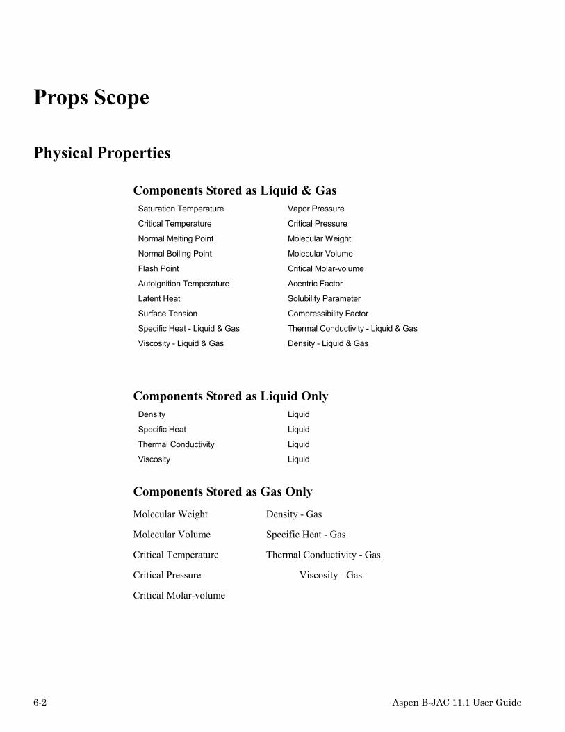
6-2 Aspen B-JAC 11.1 User Guide
Props Scope
Physical Properties
Components Stored as Liquid & GasSaturation Temperature Vapor Pressure
Critical Temperature Critical Pressure
Normal Melting Point Molecular Weight
Normal Boiling Point Molecular Volume
Flash Point Critical Molar-volume
Autoignition Temperature Acentric Factor
Latent Heat Solubility Parameter
Surface Tension Compressibility Factor
Specific Heat - Liquid & Gas Thermal Conductivity - Liquid & Gas
Viscosity - Liquid & Gas Density - Liquid & Gas
Components Stored as Liquid OnlyDensity Liquid
Specific Heat Liquid
Thermal Conductivity Liquid
Viscosity Liquid
Components Stored as Gas Only
Molecular Weight Density - Gas
Molecular Volume Specific Heat - Gas
Critical Temperature Thermal Conductivity - Gas
Critical Pressure Viscosity - Gas
Critical Molar-volume

Aspen B-JAC 11.1 User Guide 6-3
For Mixtures (up to 50 components)
Latent Heat Surface Tension
Molecular Weight Molecular Volume
Specific Heat Thermal Conductivity
Viscosity Density
VLE Two Phase Systems:CondensationVaporizationCalculation Methods:
idealSoave-Redlich-KwongPeng-RobinsonChao-SeaderUniquacVan LaarWilsonNRTL
Components:immiscibleimmisciblenoncondensable
Types of Condensation:integraldifferential
Systems of Measure
U.S., SI, or Metric

6-4 Aspen B-JAC 11.1 User Guide
Input
Application Options
Retrieve Properties
You may select if you want to retrieve physical properties at a single temperature point, overa range of temperatures, or to produce a vapor liquid equilibrium curve with liquid and vaporproperties and a heat release curve.
At one temperature point: If you select the mode that gives the properties at a singletemperature, you need to specify only the starting temperature and the pressure.
Optionally, you can determine the saturation temperature or saturation pressure for a singlecomponent that has properties stored for both liquid and gas phases. To request the saturationtemperature, leave the temperature input blank and specify the desired pressure in the field forpressure. The program will return the properties at the saturation temperature for the specifiedpressure. To request the saturation pressure, specify the desired temperature, and leave thepressure input field blank. The program will return the properties at the specified temperatureand the pressure that is equal to the vapor pressure at that temperature.
Over a temperature range: If you select this mode, Props will give you the properties overa range of temperatures. You will provide the starting and ending temperatures, thetemperature increment, and the pressure. The maximum number of intervals is 100.Therefore, if you specify a temperature interval that is smaller than 0.01 times the differencebetween the starting and ending temperatures, the program will adjust the temperatureincrement to accommodate the full temperature range specified.
Over a temperature range with VLE calculation: If you select this mode, Props will giveyou the properties over a range of temperatures. You will provide the starting and endingtemperatures, and the pressure. The program will divide the condensing range into 20 equaltemperature intervals. A vapor-liquid equilibrium curve will also be provided over thespecified range.
Temperature starting
Enter the starting reference temperature. This temperature is required if you are referencingthe databank at a single temperature or at a range of temperatures.
Temperature ending
Enter the ending temperature if you are referencing the databank over a range of temperaturesor requesting a vapor-liquid equilibrium curve.

Aspen B-JAC 11.1 User Guide 6-5
Temperature increment
Enter the temperature increment that you want the properties to be provided if you arereferencing the databank over a range of temperatures.
Pressure (absolute)
The pressure should be specified as absolute pressure, not gauge pressure. The program usesthe pressure value in order to adjust the gaseous properties for the effect of pressure.
Flowrate total
Specify the total flow rate of the mixture if you have requested vapor-liquid equilibriuminformation. The flowrate is used in determining a heat release curve.
Property OptionsThis section is only applicable if a vapor-liquid equilibrium curve has been requested.
Condensation Curve Calculation Method
The calculation method determines which correlations the program will use to determine thevapor-liquid equilibrium. The choice of method is dependent on the degree of nonideality ofthe vapor and liquid phases and the amount of data available.
The methods can be divided into three general groups:
Ideal - correlations for ideal mixtures. The ideal method uses ideal gas laws for the vaporphase and ideal solution laws for the liquid phase. You should use this method when you donot have information on the degree of nonideality. This method allows for up to 50components.
Uniquac, Van Laar, Wilson, and NRTL - correlations for nonideal mixtures which requireinteraction parameters. These methods are limited to ten components. The Uniquac, VanLaar, Wilson, and NRTL methods need binary interaction parameters for each pair ofcomponents. The Uniquac method also needs a surface parameter and volume parameter andthe NRTL method requires an additional Alpha parameter. The Wilson method is particularlysuitable for strongly nonideal binary mixtures, e.g., solutions of alcohols with hydrocarbons.The Uniquac method is applicable for both vapor-liquid equilibrium and liquid-liquidequilibrium (immiscibles). It can be used for solutions containing small or large molecules,including polymers. In addition, Uniquac's interaction parameters are less temperaturedependent than those for Van Laar and Wilson.

6-6 Aspen B-JAC 11.1 User Guide
Soave-Redlich-Kwong, Peng-Robinson, and Chao-Seader - correlations for nonidealmixtures which do not require interaction parameters. The Soave-Redlich-Kwong and Peng-Robinson methods can be used on a number of systems containing hydrocarbons, nitrogen,carbon dioxide, carbon monoxide, and other weakly polar components. They can also beapplied with success to systems which form an azeotrope, and which involve associatingsubstances such as water and alcohols. They can predict vapor phase properties at any givenpressure. The Chao-Seader method uses Redlich-Kwong equations for vapor phasenonideality and an empirical correlation for liquid phase nonideality. It is used with success inthe petroleum industry. It is recommended for use at pressures less than 68 bar (1000 psia)and temperatures greater than -18°C (0°F). The program uses the original Chao-Seadercorrelation with the Grayson-Streed modification. There is no strict demarcation betweenthese two methods since they are closely related. These methods allow for up to 50components.
Condensation Curve Calculation Type
For a condensing stream, you should determine if your case is closer to integral or differentialcondensation.
Integral condensation assumes that the vapor and liquid condensate are kept close enoughtogether to maintain equilibrium, and that the condensate formed at the beginning of thecondensing range is carried through with the vapor to the outlet. Vertical tube sidecondensation is the best case of integral condensation. Other cases which closely approachintegral condensation are: horizontal tube side condensation, vertical shell side condensation,and horizontal shell side crossflow condensation (X-shell).
In differential condensation the liquid condensate is removed from the vapor, thus changingthe equilibrium and lowering the dew point of the remaining vapor. The clearest case ofdifferential condensation is seen in the knockback reflux condenser, where the liquidcondensate runs back toward the inlet while the vapor continues toward the outlet.
Shell side condensation in a horizontal E or J shell is somewhere between true integralcondensation and differential condensation. If you want to be conservative, treat these casesas differential condensation. However, the industry has traditionally designed them as integralcondensation.
More condensate will be present at any given temperature with integral condensation versusdifferential condensation. In the heat exchanger design, this results in a higher meantemperature difference for integral condensation compared to differential condensation.

Aspen B-JAC 11.1 User Guide 6-7
Effect of pressure drop on condensation
The program will default to calculating the condensing curve in isobaric conditions (constantoperating pressure). You may specify nonisobaric conditions and the program will allocatethe specified pressure drop based on temperature increments along the condensing curve. Thevapor/liquid equilibrium at various temperature points will be calculated using an adjustedoperating pressure.
Estimated pressure drop for hot side
Provide the estimated hot side pressure drop through the exchanger. The program will use thispressure drop to adjust the VLE curve. If actual pressure varies more than 20% from thisestimated pressure drop, adjust this value to the actual and rerun Aspen Hetran. The VLEcalculation program will not permit the condensate to re-flash. If calculations indicate thatthis is happening, the program will suggest using a lower estimated pressure drop.
Vaporization Curve Calculation Method
The calculation method determines which correlations the program will use to determine thevapor-liquid equilibrium. The choice of method is dependent on the degree of nonideality ofthe vapor and liquid phases and the amount of data available.
The methods can be divided into three general groups:
Ideal - correlations for ideal mixtures. The ideal method uses ideal gas laws for the vaporphase and ideal solution laws for the liquid phase. You should use this method when you donot have information on the degree of nonideality. This method allows for up to 50components.
Uniquac, Van Laar, Wilson, and NRTL - correlations for nonideal mixtures which requireinteraction parameters. These methods are limited to ten components. The Uniquac, VanLaar, Wilson, and NRTL methods need binary interaction parameters for each pair ofcomponents. The Uniquac method also needs a surface parameter and volume parameter andthe NRTL method requires an additional Alpha parameter. The Wilson method is particularlysuitable for strongly nonideal binary mixtures, e.g. solutions of alcohols with hydrocarbons.The Uniquac method is applicable for both vapor-liquid equilibrium and liquid-liquidequilibrium (immiscibles). It can be used for solutions containing small or large molecules,including polymers. In addition, Uniquac's interaction parameters are less temperaturedependent than those for Van Laar and Wilson.

6-8 Aspen B-JAC 11.1 User Guide
Soave-Redlich-Kwong, Peng-Robinson, and Chao-Seader - correlations for nonidealmixtures which do not require interaction parameters. The Soave-Redlich-Kwong and Peng-Robinson methods can be used on a number of systems containing hydrocarbons, nitrogen,carbon dioxide, carbon monoxide, and other weakly polar components. They can also beapplied with success to systems which form an azeotrope, and which involve associatingsubstances such as water and alcohols. They can predict vapor phase properties at any givenpressure. The Chao-Seader method uses Redlich-Kwong equations for vapor phasenonideality and an empirical correlation for liquid phase nonideality. It is used with success inthe petroleum industry. It is recommended for use at pressures less than 68 bar (1000 psia)and temperatures greater than -18°C (0°F). The program uses the original Chao-Seadercorrelation with the Grayson-Streed modification. There is no strict demarcation betweenthese two methods since they are closely related. These methods allow for up to 50components.
Effect of pressure drop on vaporization
The program will default to calculating the vaporization curve in isobaric conditions (constantoperating pressure). You may specify nonisobaric conditions and the program will allocatethe specified pressure drop based on temperature increments along the vaporization curve.The vapor/liquid equilibrium at various temperature points will be calculated using anadjusted operating pressure.
Estimated pressure drop for cold side
Provide the estimated hot side pressure drop through the exchanger. The program will use thispressure drop to adjust the VLE curve. If actual pressure varies more than 20% from thisestimated pressure drop, adjust this value to the actual and rerun Aspen Hetran.

Aspen B-JAC 11.1 User Guide 6-9
Composition
Composition
Enter the composition by weight flow rate or percent (default), mole flow rate or percent, orvolume flow rate or percent. For a single component you can leave Composition blank. For amulticomponent mixture you should specify the composition in accordance with the earlierinput entry for "Composition Specification". Note that percentages do not have to add up to100, since the program proportions each to the total.

6-10 Aspen B-JAC 11.1 User Guide
Component
The Aspen B-JAC Property Databank consists of over 1500 compounds and mixtures used inthe chemical process, petroleum, and other industries. You can reference the database byentering the components for the stream. For the databank component name, you can specifyeither the component name or its chemical formula. To search the databank directory, selectthe search button. You should be careful when using the chemical formula, since severalchemicals may have the same chemical formula but due to different bonding, have differentproperties. You can specify up to 50 components.
To enter your own properties for a component, select “user” for the property Source and thenprovide the properties in the Component Properties section.
Component Type
Component type field is available for all VLE applications. This field allows you to specify ifthe component is a noncondensables or immiscible components for condensing streams or ifthe component is an inert for vaporizing streams. If you are not sure of the component type,the program will attempt to determine the component type but in general it is better to identifythe type if known. If a component does not condense any liquid over the temperature range inthe exchanger, it is best to identify it as a noncondensable.

Aspen B-JAC 11.1 User Guide 6-11
Source
The Source field is currently only available for components when the program is calculatingvapor/liquid equilibrium curves. The Source of the component may be "Databank" or "User"."Databank" indicates that all component properties will be retrieved from one of the Aspen B-JAC databanks. "User" indicates that this component's physical properties are to be specifiedby the user.
Component Type
Component type field is available for all VLE applications. This field allows you to specify ifthe component is a noncondensables or immiscible components for condensing streams or ifthe component is an inert for vaporizing streams. If you are not sure of the component type,the program will attempt to determine the component type but in general it is better to identifythe type if known. If a component does not condense any liquid over the temperature range inthe exchanger, it is best to identify it as a noncondensable.
Source
The Source field is currently only available for components when the program is calculatingvapor/liquid equilibrium curves. The Source of the component may be "Databank" or "User"."Databank" indicates that all component properties will be retrieved from one of the Aspen B-JAC databanks. "User" indicates that this component's physical properties are to be specifiedby the user.
Component Properties
Allows the user to override databank properties or input properties not in the databank. Thissection is only applicable if a vapor-liquid equilibrium curve has been requested. Thephysical properties required for various applications are listed below:
Temperature: It is recommended that you specify property data for multiple temperaturepoints. The dew and bubble points of the stream are recommended. The temperatures enteredfor no phase change fluids should at least include both the inlet and outlet temperatures. Theinlet temperature of the opposite side fluid should also be included as a 3rd temperature pointfor viscous fluids. Multiple temperature points, including the inlet and outlet, should beentered when a change of phase is present.
Liquid and Vapor Properties: The necessary physical properties are dependent on the typeof application. If you are referencing the databank for a fluid, you do not need to enter anydata on the corresponding physical properties input screens. However, it is also possible tospecify any property, even if you are referencing the databank. Any specified property willthen override the value from the databank.

6-12 Aspen B-JAC 11.1 User Guide
The properties should be self-explanatory. A few clarifications follow.
Specific Heat: Provide the specific heat for the component at the referenced temperature.
Thermal Conductivity: Provide the thermal conductivity for the component at thereferenced temperature.
Viscosity: The viscosity requested is the dynamic (absolute) viscosity in centipoise or mPa*s(note that centipoise and mPa*s are equal). To convert kinematic viscosity in centistokes todynamic viscosity in centipoise or mPa*s, multiply centistokes by the specific gravity.
The Aspen Hetran program uses a special logarithmic formula to interpolate or extrapolate theviscosity to the calculated tube wall temperature. However when a liquid is relatively viscous,say greater than 5 mPa*s (5 cp), and especially when it is being cooled, the accuracy of theviscosity at the tube wall can be very important to calculating an accurate film coefficient. Inthese cases, you should specify the viscosity at a third point, which extends the viscositypoints to encompass the tube wall temperature. This third temperature point may extend to aslow (if being cooled) or as high (if being heated) as the inlet temperature on the other side.
Density: Be sure to specify density and not specific gravity. Convert specific gravity todensity by using the appropriate formula: density, lb/ft3 = 62.4 * specific gravity; density,kg/m3 = 1000 * specific gravity. The density can also be derived from the API gravity, usingthis formula: density, lb/ft3 = 8829.6 / ( API + 131.5 ).
Latent Heat: Provide latent heat for change of phase applications.
Vapor Pressure: Provide the vapor pressure for the component. If you do not enter a valuefor the vapor pressure, the program will estimate a value.
Surface Tension: Surface tension is needed for vaporizing fluids. If you do not have surfacetension information available, the program will estimate a value.
Molecular /Volume: Provide the molecular volume of the vapor for change of phaseapplications. Note, the molecular volume can be approximated by molecular weight / specificgravity at the normal boiling point.
Molecular Weight: Provide the molecular weight of the vapor for change of phaseapplications.
Critical Pressure: The critical pressure is the pressure above which a liquid cannot bevaporized no matter how high the temperature. For mixtures, the critical pressure should bethe sum of the critical pressures of each component weighted by their mole fractions. Thisinput is required to calculate the nucleate boiling coefficient. If you do not enter a value forthe critical pressure, the program will estimate a value.

Aspen B-JAC 11.1 User Guide 6-13
Interaction Parameters
The Uniquac, Van Laar, Wilson, and NRTL methods need binary interaction parameters foreach pair of components. This data is not available from the databank and must be providedby the user. An example for the NRTL parameters is shown below.
NRTL Method --Example with 3 components (Reference Dechema)
NRTL “A” Interactive Parameters –Hetran inputted parameters
1 2 3
1 -- A21 A31
2 A12 -- A32
3 A13 A23 --
NRTL “Alpha” Parameters –Hetran inputted parameters
1 2 3
1 -------- Alpha21 Alpha31
2 Alpha12 -------- Alpha32
3 Alpha13 Alpha23 --------
NRTL – Conversion from Aspen Properties parameters to Hetran parameters:
Aspen Properties NRTL Parameters – The parameters AIJ, AJI, DJI, DIJ, EIJ, EJI, FIJ, FJI,TLOWER, & TUPPER in Aspen Properties, which are not shown below, are not required forthe Hetran NRTL method.
Aspen Properties NRTL Interactive Parameters
Component I Component 1 Component 1 Component 2
Component J Component 2 Component 3 Component 3
BIJ BIJ12 BIJ13 BIJ23
BJI BJI12 BJI13 BJI23
CIJ CIJ12 CIJ13 CIJ23

6-14 Aspen B-JAC 11.1 User Guide
“A” Interactive Parameters – Conversion from Aspen Properties to Hetran
1 2 3
1 -- A21=BJI12*1.98721 A31=BJI13*1.98721
2 A12=BIJ12*1.98721 -- A32-BJI23*1.98721
3 A13=BIJ13*1.98721 A23=BIJ23*1.98721 --
“Alpha” Parameters – Conversion from Aspen Properties to Hetran
1 2 3
1 -- Alpha21=CIJ12 Alpha31=CIJ13
2 Alpha12= CIJ12 -- Alpha32=CIJ23
3 Alpha13=CIJ13 Alpha23=CIJ23 --
NRTL – Alpha parameters
The NRTL method requires binary interaction parameters for each pair of components and anadditional Alpha parameter. This data is not available from the databank.
Uniquac – Surface & Volume parameters
The Uniquac method requires binary interaction parameters for each pair of components andalso needs a surface parameter and volume parameter. This data is not available from thedatabank.

Aspen B-JAC 11.1 User Guide 6-15
ResultsThe Props program gives you the option of requesting properties at a single temperature or atup to 100 temperatures. If you request properties at a single temperature you will also retrievethe properties which are not temperature dependent (e.g. molecular weight).
Warnings & MessagesProps provides an extensive system of warnings and messages to help the designer of heatexchanger design. Messages are divided into five types. There are several messages built intothe Props program.
Warning Messages
These are conditions, which may be problems, however the program will continue.
Error Messages
Conditions which do not allow the program to continue.
Limit Messages
Conditions which go beyond the scope of the program.
Notes
Special conditions which you should be aware of.
Suggestions
Recommendations on how to improve the design.

6-16 Aspen B-JAC 11.1 User Guide
All Properties at One Temperature
If you select this option, PROPS will display the following properties:

Aspen B-JAC 11.1 User Guide 6-17
Properties Over a Range of Temperatures
If you select this option, PROPS will display the following properties:
Specific Heat of a Liquid & Gas Latent Heat
Viscosity of Liquid & Gas Vapor Pressure
Thermal Conductivity of Liquid & Gas Surface Tension
Density of Liquid & Gas

6-18 Aspen B-JAC 11.1 User Guide
VLEIf the VLE calculation was selected, Props will generate a vapor-liquid equilibrium curve.Heat load, composition, and physical properties per temperature increment will be provided.

Aspen B-JAC 11.1 User Guide 6-19
Props Logic
Structure of Databank
The data in the databank is derived from a wide variety of published sources. For constantproperties (e.g. molecular weight), the actual value has been stored in the databank. Fortemperature dependent properties, various property specific equations are used to determinethe property at the desired temperature. In these cases, the coefficients for the equation arestored in the databank.
Vapor pressures are stored using two equations - one for temperatures below the normalboiling point and one for temperatures above the normal boiling point.
Temperature Ranges
There is a separate temperature range of validity stored in the databank for each property. Thetemperature range shown in the Databank Directory is the minimum range for all properties ofthe respective phase. Therefore some properties may have a wider range than shown in thedirectory.

6-20 Aspen B-JAC 11.1 User Guide
If you request a property at a temperature outside its valid temperature range, the programwill display a warning and then determine that property at the appropriate temperature limit(i.e., it will not extrapolate), except for liquid viscosity and vapor pressure. The programextrapolates above and below the valid temperature range for vapor pressure. It extrapolatesabove for the liquid viscosity.
Effect of Pressure
The program attempts to correct the gaseous properties as a function of pressure (liquidproperties are assumed to be independent of pressure). To do this, the program uses ageneralized correlation for all components except water/steam. The generalized correlation isreasonably accurate for most cases. However, it tends to deviate from actual measured valueswhen the temperature or pressure approach the critical region.
For water (stored under the names WATER and STEAM), the program uses a series ofspecialized equations which predict the corrected steam properties to within 1% of the valuesin the ASME Steam Tables.
Mixtures
The Props program can calculate the composite properties for multicomponent mixtures forup to 50 components.
Some care should be taken in using the databank for mixtures. Some mixtures, such asimmiscibles or binary mixtures where water is one of the components, do not conform to theequations. For this reason, some of the more common water solutions have been included inthe databank as single components.
Mixtures are calculated according to the following techniques:
Density of Liquid
ρρ
mwi i
=1
Σ( / )
Latent Heat averaged in proportion to the weight percent
Molecular Volume averaged in proportion to the mole percent
Specific Heat of Gas averaged in proportion to the weight percent
Specific Heat Liquid averaged in proportion to the weight percent
Surface Tension averaged in proportion to the mole percent

Aspen B-JAC 11.1 User Guide 6-21
Thermal Conductivity of Gas - Friend & Adler Equation
ky k M
y Mmi i i
i i=
⋅ ⋅⋅
ΣΣ
( )( )
.
.
0 33
0 33
Thermal Conductivity of Liquid - averaged in proportion to the weight percent
Viscosity of Gas - Herning & Zipperer Equation
µµ
mi i i
i i
y My M
=⋅ ⋅
⋅Σ
Σ( )
( )
.
.
0 5
0 5
Viscosity of Liquid - Arrhenius Equation
ln lnµ µm i ix= ⋅Σ
Nomenclature:
µ =viscosity w=weight fraction M=molecular weight
k=thermal cond. X=mole fraction I=i-th component
ρ=density y=gas phase mole fraction m=mixture

6-22 Aspen B-JAC 11.1 User Guide
ReferencesFor a further understanding of subjects relating to PROPS, you can refer to the followingpublications:
Sources
The properties in the databank have come from a wide range of published sources. Some havecome from product bulletins published by chemical manufacturers. Many others have comefrom the following references:
Physical and Thermodynamic Properties of Pure Chemicals, T. E. Daubert and R. P. Danner,Hemisphere Publishing Corporation, New York, 1989.
ASME Steam Tables, Meyer et al., Third Edition, The American Society of MechanicalEngineers, New York, 1977.
Perry's Chemical Engineering Handbook, Robert H. Perry and Don Green, Sixth Edition,McGraw-Hill, New York, 1984.
Physical Properties of Hydrocarbons, R. W. Gallant, Gulf Publishing Company, Houston,1968.
Physical Properties, Carl L. Yaws, McGraw-Hill, New York, 1977.
Technical Data Book - Petroleum Refining, Second Edition, American Petroleum Institute,Washington D.C., 1970.
Engineering Data Book, Tenth Edition, Gas Processors Suppliers Association, Tulsa, 1987.
Lange's Handbook of Chemistry, John A. Dean, Thirteenth Edition, McGraw-Hill, New York,1985.
Handbook of Vapor Pressures and Heats of Vaporization of Hydrocarbons and RelatedCompounds, B. J. Zwolinski and R. C. Wilhoit, Thermodynamics Research Center, CollegeStation, Texas, 1971.
Mixture Correlations
The Properties of Gases and Liquids, Robert C. Reid, John M. Prausnitz, and Bruce E.Poling, Fourth Edition, McGraw-Hill, New York, 1987.

Aspen B-JAC 11.1 User Guide 6-23
Databank Symbols
Component Name SynonymMolec.Weight ID No.
Temperature Range ºCLiquid Phase Gas Phase
Abietic acid ABIETIC ACID 302.5 D2256 173 > 342 376 > 726
Acenaphthene ACENAPHTHENE 154.2 D808 93 > 277 277 > 726
Acetal ACETAL 118.2 D1432 28 > 103 103 > 726
Acetaldehyde AALDEHYD 44.05 B74 -80 > 159 -80 > 174
D1002 -123 > 20 0 > 726
Acetamide ACETAMIDE 59.07 D2853 80 > 221 221 > 726
Acetanilide ACETANILIDE 135.2 D5870 139 > 303 303 > 726
Acetic acid ACETACID 60.50 B51 19 > 239 19 > 239
D1252 16 > 117 21 > 413
Acetic anhydride ACETANHY 102.1 B77 -40 > 239 -40 > 499
D1291 -23 > 76 139 > 726
Acetoacetanilide ACETOACETANILIDE 177.2 D5868 128 > 318 318 > 726
Acetone ACETONE 58.08 B58 -80 > 199 -80 > 269
D1051 -83 > 56 56 > 726
Acetonecyanohydrin
ACETONECYANOHYD
85.11 D1882 189 > 726
Acetonitrile ACETONIT 41.05 B127 -40 > 199 -40 > 499
D1772 1 > 81 81 > 726
Acetophenone ACETOPHENONE 120.2 D1090 19 > 126 201 > 726
Acetovanillone ACETOVANILLONE 166.2 D4849 114 > 297 297 > 726
Acetylacetone ACETYLACETONE 100.1 D1076 0 > 84 140 > 726
Acetyl chloride ACHLORID 78.50 B191 -80 > 199 -80 > 499
D1851 -19 > 50 50 > 726
Acetylene ACETYLEN 26.04 B85 -73 > 23 -73 > 371
D401 -79 > -23 -73 > 326
Acrolein ACROLEIN 56.06 B315 -80 > 119 -80 > 499
D1034 -20 > 52 52 > 726
Acrylamide ACRYLAMIDE 71.08 D1879 84 > 192 192 > 726
Acrylic acid ACRYACID 72.03 B70 19 > 199 19 > 214
D1277 12 > 101 140 > 726
Acrylonitrile VCYANIDE 53.06 B317 -17 > 93 -17 > 259
D1774 -53 > 77 24 > 726
Adipic acid ADIPIC ACID 146.1 D1285 159 > 192 337 > 726

6-24 Aspen B-JAC 11.1 User Guide
Component Name SynonymMolec.Weight ID No.
Temperature Range ºCLiquid Phase Gas Phase
Adiponitrile ADIPONITRILE 108.1 D1777 117 > 76 294 > 726
Air AIR 28.96 B3 -191 > -148 -191 >1099
D915 -198 > -158 -193 >1226
Allyl acetate ALLYL ACETATE 100.1 D1318 16 > 103 103 > 726
Allyl alcohol ALLYLALC 58.08 B63 -40 > 199 -40 > 219
D1167 7 > 95 97 > 726
Allylamine ALLYLAMINE 57.10 D1740 26 > 53 53 > 726
Allyl methacrylate ALLYL METHACRYLA 126.2 D2354 26 > 139 139 > 726
Aluminum ALUMINUM 26.98 D2925
Aluminum chloride ALUMINUM CHLORID 133.3 D2926
Aluminumhydroxide
ALUMINUM HYDROXI 78.00 D1915
Aluminum oxide ALUMINUM OXIDE 102.0 D2927
Aluminumphosphate (ortho)
ALUMINUMPHOSPHA
122.0 D1933
Aluminum sulfate ALUMINUM SULFATE 342.2 D2968
p-Aminoazobenzene
P-AMINOAZOBENZEN 197.2 D2786 359 > 726
p-Aminodiphenyl P-AMINODIPHENYL 169.2 D2787 135 > 301 301 > 726
p-Aminodiphenylamine
P-AMINODIPHENYLA 184.2 D1747 67 > 353 353 > 726
2-Aminoethoxyethanol
DGAMINE 105.1 B326 0 > 315
D2865 76 > 240 240 > 726
n-Aminoethylethanolamine
N-AMINOETHYL ETH 104.2 D2732 75 > 243 243 > 726
n-Aminoethylpiperazine
N-AMINOETHYL PIP 129.2 D1750 80 > 220 220 > 726
6-Aminohexanol 6-AMINOHEXANOL 117.2 D1871 67 > 234 234 > 726
1-Amino-2-propanol 1-AMINO-2-PROPAN 75.11 D5860 29 > 159 159 > 726
3-Amino-1-propanol 3-AMINO-1-PROPAN 75.11 D5859 51 > 187 187 > 726
Ammonia NH3 17.03 B64 -80 > 64 -80 > 426
D1911 -77 > 111 -33 > 726
Ammonia 26 wt % AMMON-26 18.00 B199 0 > 121
Ammonium acetate AMMONIUMACETATE
77.08 D2929

Aspen B-JAC 11.1 User Guide 6-25
Component Name SynonymMolec.Weight ID No.
Temperature Range ºCLiquid Phase Gas Phase
Ammoniumbisulfate
AMMONIUM BISULFA 115.1 D2949
Ammonium bisulfite AMMONIUM BISULFI 99.11 D2947
Ammonium chloride AMMONIUM CHLORID 53.49 D2928
Ammoniumhydroxide
AMMONIUM HYDROXI 35.05 D1916
Ammonium nitrate AMMONIUM NITRATE 80.04 D1990
Ammonium oxalate AMMONIUMOXALATE
124.1 D2948
Ammoniumperchlorate
AMMONIUMPERCHLO
117.5 D2944
Ammoniumphosphate
AMMONIUMPHOSPHA
115.0 D2943
Ammonium sulfate AMMONIUM SULFATE 132.1 D2967
Ammonium sulfite AMMONIUM SULFITE 116.1 D2946
Amyl alcohol AMYLALC 88.10 B89 -40 > 199 -40 > 499
p-tert-Amylphenol P-TERT-AMYLPHENO 164.2 D2196 102 > 261 261 > 726
Anethole ANETHOLE 148.2 D1420 235 > 726
Aniline ANILINE 93.06 B48 0 > 199 0 > 274
D1792 -6 > 183 183 > 726
Anisole ANISOLE 108.1 D1461 13 > 153 153 > 723
Anthracene ANTHRACENE 178.2 D804 215 > 321 342 > 726
Anthraquinone ANTHRAQUINONE 208.2 D1075 379 > 626
Antimony trichloride ANTIMONY TRICHLO 228.1 D1934
35 API distillate API35 114.2 B140 -17 > 198
28 API gas oil API28 114.2 B145 -17 > 198
56 API gasoline API56 114.2 B143 -17 > 198
42 API kerosene KEROSENE 72.15 B112 -62 > 201
34 API mid-continental crude
API34 114.2 B153 -17 > 198
76 API naturalgasoline
API76 114.2 B142 -17 > 198
10 API petroleumoil (k=11)
API10K11 18.00 B319 65 > 482
30 API petoleum oil API30 114.2 B292 -17 > 198
40 API petroleumoil
API40 114.2 B291 -17 > 198

6-26 Aspen B-JAC 11.1 User Guide
Component Name SynonymMolec.Weight ID No.
Temperature Range ºCLiquid Phase Gas Phase
45 API petroleumoil
API45 114.2 B290 -17 > 198
50 API petroleumoil
API50 114.2 B289 -17 > 198
60 API petroleumoil
API60 114.2 B288 -17 > 198
65 API petroleumoil
API65 114.2 B287 -17 > 198
70 API petroleumoil
API70 114.2 B286 -17 > 198
Argon ARGON 39.95 B185 -149 >1093
D914 -189 > -138 -149 >1093
Arsenic ARSENIC 74.92 D1992 821 >1226
Arsine ARSINE 77.95 D926 -62 > 726
Ascorbic acid ASCORBIC ACID 176.1 D5877 363 > 726
Azelaic acid AZELAIC ACID 188.2 D2257 129 > 329 360 > 726
Barium carbonate BARIUMCARBONATE
197.3 D2985
Benzaldehyde BENZALDEHYDE 106.1 D1041 6 > 126 178 > 726
Benzene BENZENE 78.10 B7 9 > 199 9 > 284
D501 5 > 80 65 > 726
1,2-Benzenediol 1,2-BENZENEDIOL 110.1 D1244 108 > 245 245 > 726
1,3-Benzenediol 1,3-BENZENEDIOL 110.1 D1245 131 > 276 276 > 726
1,2,3-Benzenetriol 1,2,3-BENZENETRI 126.1 D1248 141 > 308 308 > 726
Benzoic acid BENZOICA 122.1 B424 121 > 259 121 > 499
D1281 122 > 176 249 > 726
Benzonitrile BENZONITRILE 103.1 D1790 190 > 720
Benzophenone BENZOPHENONE 182.2 D1085 51 > 176 306 > 726
Benzothiophene BENZOTHIOPHENE 134.2 D1822 31 > 219 219 > 726
Benzotrichloride BENZOTRICHLORIDE 195.5 D1576 0 > 220 220 > 726
Benzotrifluoride BTF 146.1 B314 0 > 151
D2634 -29 > 102 103 > 723
Benzoyl chloride BENZOYL CHLORIDE 140.6 D1856 75 > 189 196 > 716
Benzyl acetate BENZYL ACETATE 150.2 D1359 -25 > 213 213 > 726
Benzyl alcohol BENZYL ALCOHOL 108.1 B381 -17 > 204 -17 > 499
D1180 19 > 86 205 > 726
Benzylamine BENZYLAMINE 107.2 D1733 24 > 184 184 > 726

Aspen B-JAC 11.1 User Guide 6-27
Component Name SynonymMolec.Weight ID No.
Temperature Range ºCLiquid Phase Gas Phase
Benzyl benzoate BENZYL BENZOATE 212.2 D1364 19 > 323 323 > 726
Benzyl chloride BENZYL CHLORIDE 126.6 D1562 -38 > 179 179 > 726
Benzyl chloride BENZYLCL 126.6 B69 -17 > 199 -17 > 234
Benzyl dichloride BENZYL DICHLORID 161.0 D1599 92 > 272 213 > 726
Benzyl ethyl ether BENZYL ETHYL ETH 136.2 D1460 2 > 184 184 > 724
Bicyclohexyl BICYCLOHEXYL 166.3 D155 3 > 86 239 > 719
Biphenyl BIPHENYL 154.2 D558 69 > 254 99 > 726
Bis(chloromethyl)ether
BIS(CHLOROMETHYL 115.0 D5857 16 > 104 104 > 726
Bis(cyanoethyl)ether
BIS(CYANOETHYL)E 124.1 D5858 118 > 305 305 > 726
Bisphenol a BISPHENOL A 228.3 D1198 182 > 360 360 > 726
Black liquor 10 %solids
BLACK10 B373 19 > 159
Black liquor 30%solids
BLACK30 B372 19 > 159
Black liquor 50%solids
BLACK50 B371 37 > 148
Black liquor 65%solids
BLACK65 B370 79 > 148
Borax BORAX 381.4 D2976
Boric acid BORIC ACID 61.83 D2901
Boron trichloride BORON TRICHLORID 117.2 D1961 -107 > 2 12 > 326
Boron trifluoride BORON TRIFLUORID 67.81 D1942 -12 > 426
Bromine BROMINE 159.8 B222 0 > 299 0 > 799
D922 -7 > 32 26 > 226
Bromobenzene BROMOBEN 157.0 B124 0 > 199 0 > 269
D1680 19 > 156 156 > 726
1-Bromobutane 1-BROMOBUTANE 137.0 D1655 -33 > 101 101 > 726
2-Bromobutane 2-BROMOBUTANE 137.0 D2638 10 > 91 91 > 726
Bromochlorodifluoromethane
BROMOCHLORODIFLU
165.4 D2686 -39 > 79 -40 > 726
Bromochloromethane
BROMOCHLOROMETHA
129.4 D2639 -87 > 68 68 > 726
Bromoethane EBROMIDE 109.0 B104 -40 > 199 -40 > 499
D1645 -73 > 38 38 > 726
1-Bromoheptane 1-BROMOHEPTANE 179.1 D1667 -33 > 178 178 > 726

6-28 Aspen B-JAC 11.1 User Guide
Component Name SynonymMolec.Weight ID No.
Temperature Range ºCLiquid Phase Gas Phase
1-Bromonaphthalene
1-BROMONAPHTHALE
207.1 D1697 281 > 726
1-Bromopropane 1-BROMOPROPANE 123.0 D1650 -33 > 70 70 > 726
2-Bromopropane 2-BROMOPROPANE 123.0 D1651 -23 > 59 59 > 726
p-Bromotoluene P-BROMOTOLUENE 171.0 D2661 26 > 184 184 > 726
Bromotrichloromethan
BROMOTRICHLOROME
198.3 D2641 20 > 104 104 > 726
Bromotrifluoroethylen
BROMOTRIFLUOROET
160.9 D2690 -57 > -2 26 > 726
Bromotrifluoromethan
BTFM 148.9 B193 -80 > 39 -80 > 499
D2687 -39 > 24 -43 > 226
1,2-Butadiene METHYL ALLENE 54.09 B220 -120 > 159 -120 > 299
D302 -136 > 10 10 > 726
1,3-Butadiene BUTADIEN 54.09 B97 -62 > 119 -62 > 499
D303 -23 > -4 -4 > 726
n-Butane BUTANE 58.12 B12 -101 > 148 -101 > 593
D5 -113 > 126 0 > 726
1,2-Butanediol 1,2-BUTANEDIOL 90.12 D1220 193 > 726
1,3-Butanediol 1,3-BUTANEDIOL 90.12 D1221 206 > 726
1,4-Butanediol 1,4-BUTANEDIOL 90.12 D1241 19 > 99 226 > 726
2,3-Butanediol 2,3-BUTANEDIOL 90.12 D1238 180 > 726
n-Butanol BUTANOL 74.12 B88 -40 > 199 -40 > 269
D1105 -83 > 117 96 > 526
sec-Butanol BUTANOLS 74.12 B162 -30 > 134 -30 > 499
D1107 14 > 99 99 > 726
tert-Butanol BUTANOLT 74.12 B186 -50 > 149 -50 > 499
D1108 25 > 178 82 > 326
cis-2-Butene BUTENEC 56.10 B147 -100 > 139 -100 > 499
D205 -138 > 3 0 > 726
trans-2-Butene BUTENET2 56.10 B159 -100 > 139 -100 > 499
D206 -105 > 0 0 > 726
1-Butene BUTENE 56.11 D204 -153 > -6 -48 > 526
cis-2-Butene-1,4-diol
CIS-2-BUTENE-1,4 88.11 D1239 10 > 234 234 > 726

Aspen B-JAC 11.1 User Guide 6-29
Component Name SynonymMolec.Weight ID No.
Temperature Range ºCLiquid Phase Gas Phase
trans-2-Butene-1,4-diol
TRANS-2-BUTENE-1 88.11 D1240 236 > 726
2-Butoxyethanol 2-BUTOXYETHANOL 118.2 D2862 1 > 126 171 > 726
n-Butyl acetate BACETATE 116.2 B179 -40 > 279 -40 > 499
D1315 16 > 125 26 > 526
sec-Butyl acetate SEC-BUTYL ACETAT 116.2 D1320 0 > 111 111 > 726
tert-Butyl acetate TERT-BUTYL ACETA 116.2 D2321 12 > 95 95 > 726
n-Butyl acrylate N-BUTYL ACRYLATE 128.2 D1344 24 > 51 147 > 726
n-Butylamine BAMINE 73.14 B105 -40 > 159 -40 > 499
D1712 -7 > 77 0 > 726
sec-Butylamine SEC-BUTYLAMINE 73.14 D1726 -23 > 62 62 > 726
tert-Butylamine TERT-BUTYLAMINE 73.14 D1727 -13 > 44 44 > 726
n-Butylbenzene BBENZENE 134.2 B294 -51 > 168 -128 > 537
D518 0 > 183 183 > 723
sec-Butylbenzene SEC-BUTYLBENZENE 134.2 D520 15 > 86 173 > 723
tert-Butylbenzene TERT-BUTYLBENZEN 134.2 D521 16 > 51 169 > 719
n-Butyl benzoate N-BUTYL BENZOATE 178.2 D1365 88 > 249 249 > 726
n-Butyl n-butyrate N-BUTYL N-BUTYRA 144.2 D1385 24 > 164 164 > 726
p-tert-butylcatechol P-TERT-BUTYLCATE 166.2 D1235 114 > 284 284 > 726
n-Butyl chloride N-BUTYL CHLORIDE 92.57 D1586 -23 > 78 78 > 726
sec-Butyl chloride SEC-BUTYL CHLORI 92.57 D1587 -23 > 68 68 > 726
tert-Butyl chloride TERT-BUTYL CHLOR 92.57 D1535 6 > 50 50 > 726
n-Butylcyclohexane N-BUTYLCYCLOHEXA
140.3 D152 -19 > 180 180 > 726
alpha-Butylene BUTENE1 56.10 B139 -80 > 119 -80 > 499
1,2-Butylene oxide BUTYLOX 72.10 B254 -40 > 124 -40 > 499
n-Butyl ethyl ether N-BUTYL ETHYL ET 102.2 D1448 -13 > 92 92 > 726
tert-Butyl ethylether
TERT-BUTYL ETHYL 102.2 D1428 -16 > 72 72 > 726
tert-Butylformamide TERT-BUTYLFORMAM
101.1 D6852 72 > 201 201 > 726
n-Butyl formate N-BUTYL FORMATE 102.1 D1304 16 > 106 106 > 726
T-Butylhydroperoxide
T-BUTYL HYDROPER 90.12 D1473 132 > 726
n-Butyl isocyanate N-BUTYL ISOCYANA 99.13 D2722 114 > 726

6-30 Aspen B-JAC 11.1 User Guide
Component Name SynonymMolec.Weight ID No.
Temperature Range ºCLiquid Phase Gas Phase
n-Butyl mercaptan N-BUTYL MERCAPTA 90.19 D1841 -112 > 41 98 > 726
sec-Butylmercaptan
SEC-BUTYL MERCAP 90.19 D1806 -140 > 84 84 > 726
tert-Butylmercaptan
BMCAPTAN 90.19 B368 1 > 121 1 > 226
D1804 1 > 64 64 > 726
n-Butylmethacrylate
N-BUTYL METHACRY 142.2 D1389 -50 > 160 160 > 720
1-n-Butylnaphthalene
1-N-BUTYLNAPHTHA 184.3 D713 1 > 126 289 > 726
n-Butyl nonanoate N-BUTYL NONANOAT 214.3 D1345 24 > 229 229 > 726
p-tert-Butylphenol P-TERT-BUTYLPHEN 150.2 D1197 111 > 239 239 > 726
n-Butyl propionate N-BUTYL PROPIONA 130.2 D1326 -89 > 146 146 > 726
n-Butyl stearate N-BUTYL STEARATE 340.6 D1383 26 > 89 349 > 726
n-Butyl valerate N-BUTYL VALERATE 158.2 D1346 19 > 186 186 > 726
Butyl vinyl ether BUTYL VINYL ETHE 100.2 D1447 -48 > 93 93 > 726
2-Butyne BUTYNE2 54.09 B190 -80 > 199 -80 > 499
2-Butyne-1,4-diol 2-BUTYNE-1,4-DIO 86.09 D1215 237 > 726
n-Butyraldehyde BALDEHYD 72.11 B192 -80 > 159 -80 > 499
D1005 -96 > 74 74 > 326
n-Butyric acid BUTYRICA 88.11 B11 0 > 279 0 > 499
D1256 -5 > 163 163 > 433
Butyric anhydride BUTYRIC ANHYDRID 158.2 D1293 19 > 197 197 > 726
gamma-Butyrolactone
BLO 86.09 B452 -1 > 204 -1 > 232
D1092 203 > 726
n-Butyronitrile BONITRIL 69.10 B187 -40 > 199 -40 > 499
D1782 -111 > 117 0 > 726
Caffeine CAFFEINE 194.2 D6853
Calcium carbonate CALCIUM CARBONAT 100.1 D2970
Calcium chloride CALCIUM CHLORIDE 111.0 D1946
Calcium chloride 15wt %
CACL2-15 18.02 B20 -6 > 93
Calcium chloride 25wt%
CACL2-25 18.02 B28 -17 > 93
Calcium fluoride CALCIUM FLUORIDE 78.07 D2971

Aspen B-JAC 11.1 User Guide 6-31
Component Name SynonymMolec.Weight ID No.
Temperature Range ºCLiquid Phase Gas Phase
Calcium hydroxide CALCIUM HYDROXID 74.09 D1914
Calcium oxide CALCIUM OXIDE 56.08 D1995
Calcium sulfate CALCIUM SULFATE 136.1 D1941
Calflo AF CALFLO AF 380.0 B466 37 > 315
Calflo HTF CALFLO HTF 380.0 B465 37 > 315
Camphene CAMPHENE 136.2 D839 46 > 160 160 > 726
Camphor CAMPHOR 152.2 D2850 207 > 726
epsilon-Caprolactam
EPSILON-CAPTAM 113.2 D1880 69 > 176 269 > 726
epsilon-Caprolactone
EPSILON-CAPTONE 114.1 D1093 112 > 240 214 > 726
Carbon CARBON 12.01 D1991
Carbon dioxide CO2 44.01 B55 -51 > 29 -18 > 749
D909 -53 > 16 -78 > 1226
Carbon disulfide CS2 76.13 B106 -80 > 159 -80 > 499
D1938 -73 > 46 0 > 526
Carbon monoxide CO 28.01 B111 -199 > -149 -199 > 815
D908 -204 > -148 -203 > 976
Carbontetrachloride
CARBOTET 153.8 B37 -10 > 199 -10 > 209
D1501 -22 > 76 -22 > 526
Carbontetrafluoride
R14 88.00 B225 -169 > -43 -169 > 399
D1616 -183 > -128 -128 > 476
Carbonyl fluoride CARBONYL FLUORID 66.01 D1850 -107 > -85 -84 > 726
Carbonyl sulfide CARBONYL SULFIDE 60.08 D1893 -138 > -50 -50 > 726
Cetyl methacrylate CETYL METHACRYLA 310.5 D2353 14 > 354 367 > 726
Chemtherm 550 CHEM550 B461 65 > 259
1-Chloro-1,1-difluoroethane
1-CHLORO-1,1-DIF 100.5 D2695 -73 > 86 -10 > 726
2-Chloro-1,1-difluoroethylene
2-CHLORO-1,1-DIF 98.48 D1612 -53 > -18 26 > 726
1-Chloro-2,4-dinitrobenzene
1-CHLORO-2,4-DIN 202.6 D4870
Chlorine CHLORINE 70.91 B6 -73 > 115 -73 > 598
D918 -83 > -34 -73 > 726

6-32 Aspen B-JAC 11.1 User Guide
Component Name SynonymMolec.Weight ID No.
Temperature Range ºCLiquid Phase Gas Phase
Chlorine dioxide CHLORINE DIOXIDE 67.45 D2977 10 > 726
4-Chloro-3-nitrobenzotrifluoride
4-CHLORO-3-NITRO 225.6 D4859
Chloroacetaldehyde
CHLOROACETALDEHY
78.50 D4867 19 > 84 84 > 726
Chloroacetic acid CHLOROACETIC ACI 94.50 D1852 69 > 126 189 > 726
Chloroacetylchloride
CHLOROACETYLCHL
112.9 D1853 17 > 105 105 > 726
m-Chloroaniline M-CHLOROANILINE 127.6 D4858 21 > 228 228 > 726
o-Chloroaniline O-CHLOROANILINE 127.6 D1859 -2 > 208 208 > 726
p-Chloroaniline P-CHLOROANILINE 127.6 D3860 103 > 126 230 > 726
o-Chlorobenzoicacid
O-CHLOROBENZOIC 156.6 D1874 141 > 286 286 > 726
p-Chlorobenzotrifluoride
P-CHLOROBENZOTRI 180.6 D1857 -19 > 138 138 > 726
m-Chlorobenzoylchloride
M-CHLOROBENZOYL 175.0 D1596 88 > 224 224 > 724
Chlorodifluoromethane
CHLORODIFLUOROME
86.47 D1604 -103 > 46 -40 > 226
2-Chloroethanol 2-CHLOROETHANOL 80.51 D2898 19 > 128 128 > 726
Chloroform CHLOROFO 119.4 B60 -40 > 199 -40 > 259
D1521 -63 > 80 0 > 526
1-Chloronaphthalene
1-CHLORONAPHTHAL
162.6 D1589 0 > 176 259 > 726
m-Chloronitrobenzene
M-CHLORONITROBEN
157.6 D2882 97 > 235 235 > 726
o-Chloronitrobenzene
O-CHLORONITROBEN
157.6 D4882 105 > 245 245 > 726
p-Chloronitrobenzene
P-CHLORONITROBEN
157.6 D4883 102 > 241 241 > 726
Chloropentafluoroethane
CHLOROPENTAFLUOR
154.5 D2692 -83 > -39 -23 > 226
1-Chloropentane 1-CHLOROPENTANE 106.6 D1588 -98 > 108 108 > 726
m-Chlorophenol M-CHLOROPHENOL 128.6 D2893 91 > 213 213 > 726
o-Chlorophenol O-CHLOROPHENOL 128.6 D2892 9 > 174 174 > 726
p-Chlorophenol P-CHLOROPHENOL 128.6 D2894 95 > 219 219 > 726
Chloroprene CHLORPRE 88.54 B296 -17 > 259 -17 > 537
D1583 -62 > 59 59 > 726
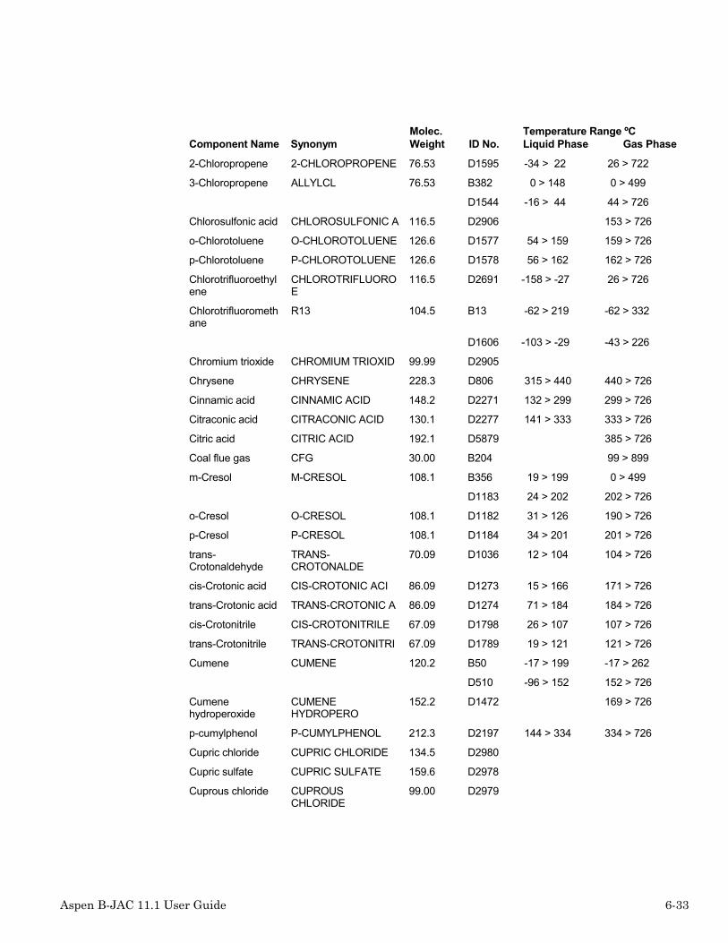
Aspen B-JAC 11.1 User Guide 6-33
Component Name SynonymMolec.Weight ID No.
Temperature Range ºCLiquid Phase Gas Phase
2-Chloropropene 2-CHLOROPROPENE 76.53 D1595 -34 > 22 26 > 722
3-Chloropropene ALLYLCL 76.53 B382 0 > 148 0 > 499
D1544 -16 > 44 44 > 726
Chlorosulfonic acid CHLOROSULFONIC A 116.5 D2906 153 > 726
o-Chlorotoluene O-CHLOROTOLUENE 126.6 D1577 54 > 159 159 > 726
p-Chlorotoluene P-CHLOROTOLUENE 126.6 D1578 56 > 162 162 > 726
Chlorotrifluoroethylene
CHLOROTRIFLUOROE
116.5 D2691 -158 > -27 26 > 726
Chlorotrifluoromethane
R13 104.5 B13 -62 > 219 -62 > 332
D1606 -103 > -29 -43 > 226
Chromium trioxide CHROMIUM TRIOXID 99.99 D2905
Chrysene CHRYSENE 228.3 D806 315 > 440 440 > 726
Cinnamic acid CINNAMIC ACID 148.2 D2271 132 > 299 299 > 726
Citraconic acid CITRACONIC ACID 130.1 D2277 141 > 333 333 > 726
Citric acid CITRIC ACID 192.1 D5879 385 > 726
Coal flue gas CFG 30.00 B204 99 > 899
m-Cresol M-CRESOL 108.1 B356 19 > 199 0 > 499
D1183 24 > 202 202 > 726
o-Cresol O-CRESOL 108.1 D1182 31 > 126 190 > 726
p-Cresol P-CRESOL 108.1 D1184 34 > 201 201 > 726
trans-Crotonaldehyde
TRANS-CROTONALDE
70.09 D1036 12 > 104 104 > 726
cis-Crotonic acid CIS-CROTONIC ACI 86.09 D1273 15 > 166 171 > 726
trans-Crotonic acid TRANS-CROTONIC A 86.09 D1274 71 > 184 184 > 726
cis-Crotonitrile CIS-CROTONITRILE 67.09 D1798 26 > 107 107 > 726
trans-Crotonitrile TRANS-CROTONITRI 67.09 D1789 19 > 121 121 > 726
Cumene CUMENE 120.2 B50 -17 > 199 -17 > 262
D510 -96 > 152 152 > 726
Cumenehydroperoxide
CUMENEHYDROPERO
152.2 D1472 169 > 726
p-cumylphenol P-CUMYLPHENOL 212.3 D2197 144 > 334 334 > 726
Cupric chloride CUPRIC CHLORIDE 134.5 D2980
Cupric sulfate CUPRIC SULFATE 159.6 D2978
Cuprous chloride CUPROUSCHLORIDE
99.00 D2979

6-34 Aspen B-JAC 11.1 User Guide
Component Name SynonymMolec.Weight ID No.
Temperature Range ºCLiquid Phase Gas Phase
Cyanogen CYANOGEN 52.04 D1799 -27 > -21 -21 > 326
Cyanogen chloride CYANOGENCHLORID
61.47 D1594 -4 > 12 12 > 726
Cyclobutane CBUTANE 56.10 B241 -80 > 119 -80 > 499
D102 -83 > 12 12 > 726
Cycloheptane CYCLOHEPTANE 98.19 D159 -8 > 118 118 > 726
1,3-Cyclohexadiene
1,3-CYCLOHEXADIE 80.13 D331 -93 > 80 80 > 726
Cyclohexane CYCLOHEX 84.16 B57 9 > 204 9 > 294
D137 11 > 80 51 > 626
1,4-Cyclohexanedicarboxylic acid
1,4-CYCLOHEXANED 172.2 D1264 312 > 395 395 > 726
Cyclohexanol CYCLOHEXANOL 100.2 D1151 23 > 160 160 > 726
Cyclohexanone CHEXANON 98.15 B338 -17 > 148 -17 > 499
D1080 16 > 155 155 > 726
Cyclohexanoneoxime
CYCLOHEXANONEOX
113.2 D4887 207 > 726
Cyclohexene CHEXENE 82.14 B246 -40 > 239 -40 > 499
D270 0 > 82 82 > 722
Cyclohexylamine CYCLOHEXYLAMINE 99.18 D1729 34 > 132 134 > 726
Cyclohexylbenzene CYCLOHEXYLBENZEN
160.3 D557 6 > 240 240 > 726
2-Cyclohexylcyclohexanone
2-CYCLOHEXYL CYC 180.3 D1097 24 > 263 263 > 726
Cyclohexylisocyanate
CYCLOHEXYL ISOCY 125.2 D2723 168 > 726
Cyclohexylperoxide
CYCLOHEXYLPEROX
116.2 D1474 216 > 726
Cyclooctadiene COCTDIEN 108.2 B236 -40 > 214 -40 > 499
1,5-Cyclooctadiene 1,5-CYCLOOCTADIE 108.2 D333 -69 > 150 150 > 726
Cyclopentadiene CYCLOPENTADIENE 66.10 D315 -73 > 41 41 > 726
Cyclopentane CPENTANE 70.13 B242 -80 > 139 -80 > 499
D104 -48 > 49 0 > 326
Cyclopentanone CYCLOPENTANONE 84.12 D1079 44 > 86 130 > 726
Cyclopentene CPENTENE 68.11 B256 -40 > 199 -40 > 499
D269 -135 > 44 44 > 726

Aspen B-JAC 11.1 User Guide 6-35
Component Name SynonymMolec.Weight ID No.
Temperature Range ºCLiquid Phase Gas Phase
Cyclopropane CPROPANE 42.08 B255 -80 > 69 -80 > 499
D101 -123 > -33 -32 > 172
m-Cymene M-CYMENE 134.2 D523 -63 > 175 175 > 725
o-Cymene O-CYMENE 134.2 D522 -23 > 178 178 > 718
p-Cymene CYMENE 134.2 B47 19 > 315 19 > 315
D524 -67 > 177 177 > 726
Decafluorobutane DECAFLUOROBUTANE
238.0 D1622 -56 > -2 26 > 726
cis-Decahydronaphthalene
CIS-DECAHYDRONAP
138.3 D153 19 > 195 195 > 726
trans-Decahydronaphthalene
TRANS-DECAHYDRON
138.3 D154 19 > 187 187 > 726
1-Decanal 1-DECANAL 156.3 D1020 55 > 214 214 > 726
n-Decane DECANE 142.3 B257 -17 > 162 -17 > 426
D56 -29 > 56 174 > 726
n-Decanoic acid N-DECANOIC ACID 172.3 D1254 31 > 191 269 > 726
1-Decanol 1-DECANOL 158.3 D1136 27 > 157 230 > 726
1-Decene 1-DECENE 140.3 D260 0 > 170 170 > 726
n-Decylamine N-DECYLAMINE 157.3 D2710 58 > 218 220 > 726
n-Decylbenzene N-DECYLBENZENE 218.4 D554 -14 > 297 297 > 726
n-Decylcyclohexane
N-DECYLCYCLOHEXA
224.4 D158 -1 > 126 297 > 726
n-Decyl mercaptan N-DECYL MERCAPTA 174.4 D1826 24 > 239 239 > 726
1-n-Decylnaphthalene
1-N-DECYLNAPHTHA 268.4 D712 14 > 226 378 > 726
Dehydroabietylamine
DEHYDROABIETYLAM
285.5 D1730 158 > 368 386 > 726
Deuterium DEUTERIUM 4.03 D925 -39 > 206
Deuterium oxide DEUTERIUM OXIDE 20.03 D1997 3 > 99 101 > 726
Dextrose DEXTROSE 180.2 D4881
Diacetone alcohol DIACETONE ALCOHO 116.2 D2854 -43 > 96 168 > 718
Diallyl maleate DIALLYL MALEATE 196.2 D2381 73 > 243 246 > 726
Diamylamine DIAMYLAMINE 157.3 D3722 46 > 196 202 > 726
Dibenzofuran DIBENZOFURAN 168.2 D1480 284 > 726
Dibenzopyrrole DIBENZOPYRROLE 167.2 D2789 354 > 726

6-36 Aspen B-JAC 11.1 User Guide
Component Name SynonymMolec.Weight ID No.
Temperature Range ºCLiquid Phase Gas Phase
Dibenzyl ether DIBENZYL ETHER 198.3 D1463 3 > 176 288 > 726
Diborane DIBORANE 27.67 D1983 -92 > 726
m-Dibromobenzene M-DIBROMOBENZENE
235.9 D1678 35 > 217 217 > 726
Dibromodifluoromethane
DIBROMODIFLUOROM
209.8 D2688 -34 > 22 22 > 726
1,1-Dibromoethane 1,1-DIBROMOETHAN 187.9 D1672 -62 > 107 107 > 726
1,2-Dibromoethane EDB 187.9 B154 19 > 259 19 > 499
D1673 9 > 131 131 > 726
Dibromomethane DIBROMOMETHANE 173.8 D2637 -33 > 96 96 > 726
1,2-Dibromotetrafluoroethane
1,2-DIBROMOTETRA 259.8 D1611 -46 > 49 47 > 726
Di-n-butylamine DBA 129.2 B144 -40 > 234 -40 > 499
D1744 27 > 158 158 > 726
2,6-Di-tert-butyl-p-cresol
2,6-DI-TERT-BUTY 220.4 D2113 86 > 264 264 > 726
Di-n-butyl ether BETHER 130.2 B253 -80 > 249 -80 > 499
D1404 -95 > 140 46 > 726
Di-sec-butyl ether DI-SEC-BUTYL ETH 130.2 D1406 26 > 121 121 > 726
Di-tert-butyl ether DI-TERT-BUTYL ET 130.2 D1423 1 > 107 107 > 726
Dibutyl maleate DIBUTYL MALEATE 228.3 D2382 84 > 254 279 > 726
Di-t-butyl peroxide DI-T-BUTYL PEROX 146.2 D1482 110 > 726
Dibutyl phthalate DIBUTYL PHTHALAT 278.3 D2376 20 > 146 339 > 526
Dibutyl sebacate DIBUTYL SEBACATE 314.5 D1384 0 > 176 348 > 726
Di-n-butyl sulfone DI-N-BUTYL SULFO 178.3 D1849 110 > 290 290 > 726
1,3-Dichloro-trans-2-butene
1,3-DICHLORO-TRA 125.0 D1598 35 > 128 128 > 726
1,4-Dichloro-cis-2-butene
1,4-DICHLORO-CIS 125.0 D1593 46 > 152 152 > 726
1,4-Dichloro-trans-2-butene
1,4-DICHLORO-TRA 125.0 D1505 0 > 156 156 > 726
3,4-Dichloro-1-butene
3,4-DICHLORO-1-B 125.0 D1597 21 > 114 114 > 726
1,2-Dichloro-4-nitrobenzene
1,2-DICHLORO-4-N 192.0 D4880
Dichloroacetaldehyde
DICHLOROACETALDE
112.9 D4868 4 > 88 88 > 726

Aspen B-JAC 11.1 User Guide 6-37
Component Name SynonymMolec.Weight ID No.
Temperature Range ºCLiquid Phase Gas Phase
Dichloroacetic acid DICHLOROACETIC A 128.9 D3853 13 > 106 193 > 726
Dichloroacetylchloride
DICHLOROACETYL C 147.4 D1854 19 > 107 107 > 726
3,4-Dichloroaniline 3,4-DICHLOROANIL 162.0 D4879 126 > 271 271 > 726
m-Dichlorobenzene DCB 147.0 B302 -17 > 204 -17 > 272
D1573 -24 > 126 173 > 726
o-Dichlorobenzene O-DICHLOROBENZEN
147.0 D1572 0 > 78 180 > 726
p-Dichlorobenzene P-DICHLOROBENZEN 147.0 D1574 52 > 174 174 > 726
2,4-Dichlorobenzotrifluoride
2,4-DICHLOROBENZ 215.0 D1858 -6 > 177 177 > 717
1,4-Dichlorobutane 1,4-DICHLOROBUTA 127.0 D1508 -37 > 153 153 > 726
Dichlorodifluoromethane
R12 120.9 B16 -62 > 93 -84 > 399
D1601 -103 > 86 -23 > 301
1,1-Dichloroethane 1,1-DICHLOROETHA 98.96 D1522 -48 > 57 57 > 326
1,2-Dichloroethane EDC 98.97 B78 -17 > 199 -17 > 292
D1523 -19 > 83 83 > 287
cis-1,2-Dichloroethylene
DCEC 96.95 B163 -20 > 174 -20 > 499
D1580 -64 > 60 60 > 426
trans-1,2-Dichloroethylene
DCET 96.95 B155 -20 > 174 -20 > 499
D1581 -49 > 47 47 > 426
1,1-Dichloroethylene
1,1-DICHLOROETHY 96.94 D1591 -122 > 31 31 > 399
Dichlorofluoromethane
R21 102.9 B227 -80 > 159 -100 > 399
D1696 -63 > 99 6 > 176
Dichloromethane MECHLOR 84.90 B95 -62 > 199 -62 > 499
D1511 -58 > 46 6 > 726
1,5-Dichloropentane
1,5-DICHLOROPENT 141.0 D1509 -72 > 179 179 > 726
3,4-Dichlorophenylisocyanate
3,4-DICHLOROPHEN 188.0 D4860 93 > 201 227 > 726
1,1-Dichloropropane
1,1-DICHLOROPROP 113.0 D2526 6 > 88 88 > 726

6-38 Aspen B-JAC 11.1 User Guide
Component Name SynonymMolec.Weight ID No.
Temperature Range ºCLiquid Phase Gas Phase
1,2-Dichloropropane
PROPYLDC 113.0 B117 -73 > 191 -73 > 499
D1526 -48 > 89 96 > 726
1,3-Dichloropropane
1,3-DICHLOROPROP 113.0 D2527 28 > 120 120 > 726
2,3-Dichloropropene
2,3-DICHLOROPROP 111.0 D2545 26 > 92 92 > 726
Dichlorosilane DICHLOROSILANE 101.0 D1935 -122 > 128 8 > 326
1,2-Dichlorotetrafluoroethane
1,2-DICHLOROTETR 170.9 D1609 -39 > 99 3 > 226
2,4-Dichlorotoluene 2,4-DICHLOROTOLU 161.0 D1579 -13 > 201 201 > 721
Dicumyl peroxide DICUMYL PEROXIDE 270.4 D1475
trans-Dicyano-1-butene
TRANS-DICYANO-1- 106.1 D2734 45 > 225 225 > 726
1,4-Dicyano-2-butene
1,4-DICYANO-2-BU 106.1 D2735 84 > 273 273 > 726
cis-Dicyano-1-butene
CIS-DICYANO-1-BU 106.1 D2733 45 > 227 227 > 726
Dicyclohexylamine DICYCLOHEXYLAMIN 181.3 D2730 95 > 255 255 > 726
Dicyclopentadiene DICYCLOPENTADIEN 132.2 D316 31 > 169 169 > 726
Diethanolamine DEAMINE 105.1 B331 37 > 148
D1724 27 > 176 268 > 726
Diethlene glycol 20wt %
DEGLY-20 18.00 B244 -1 > 148
Diethlene glycol 80wt %
DEGLY-80 18.00 B245 -1 > 148
1,2-diethoxyethane 1,2-DIETHOXYETHA 118.2 D2456 7 > 121 121 > 726
Diethylamine DEA 73.14 B92 -40 > 199 -40 > 249
D1710 -24 > 55 0 > 726
n,n-Diethylaniline N,N-DIETHYLANILI 149.2 D1753 28 > 216 216 > 726
2,6-Diethylaniline 2,6-DIETHYLANILI 149.2 D2791 65 > 225 235 > 726
m-Diethylbenzene M-DIETHYLBENZENE 134.2 D526 -83 > 176 181 > 721
o-Diethylbenzene O-DIETHYLBENZENE 134.2 D525 -31 > 183 183 > 726
p-Diethylbenzene P-DIETHYLBENZENE 134.2 D527 -42 > 183 183 > 726
Diethyl carbonate DIETHYL CARBONAT 118.1 D1392
Diethyl disulfide DIETHYL DISULFID 122.3 D1824 -101 > 26 153 > 726

Aspen B-JAC 11.1 User Guide 6-39
Component Name SynonymMolec.Weight ID No.
Temperature Range ºCLiquid Phase Gas Phase
Diethylene glycol DEGLY 106.1 B332 9 > 154 9 > 499
D1202 -3 > 126 244 > 726
Diethylene glycoldi-n-butyl ether
DIETHYLENE GDBE 218.3 D1459 19 > 151 255 > 726
Diethylene glycoldiethyl ether
DIETHYLENE GDEE 162.2 D1458 9 > 188 188 > 726
Diethylene glycoldimethyl ether
DIETHYLENE GDME 134.2 D1456 -69 > 126 159 > 726
Diethylene glycolethyl ether acetate
DIETHYLENE GEEA 176.2 D5885 56 > 216 217 > 726
Diethylene glycolmonobutyl ether
DIETHYLENE GME 162.2 D4857 53 > 213 230 > 726
Diethylene glycol 40wt %
DEGLY-40 18.00 B249 -1 > 148
Diethylene glycol 60wt %
DEGLY-60 18.00 B250 -1 > 148
Diethylene triamine DIETHYLENE TRIAM 103.2 D2717 64 > 207 207 > 726
Diethyl ether EETHER 74.12 B149 -40 > 159 -40 > 499
D1402 -73 > 99 -73 > 326
Diethyl maleate DIETHYL MALEATE 172.2 D2386 66 > 224 224 > 726
Diethyl malonate DIETHYL MALONATE 160.2 D1394 -33 > 126 198 > 726
Diethyl oxalate DIETHYL OXALATE 146.1 D1393 -13 > 86 185 > 726
3,3-diethylpentane 3,3-DIETHYLPENTA 128.3 D50 -33 > 146 146 > 726
Diethyl phthalate DIETHYL PHTHALAT 222.2 D2375 -4 > 176 293 > 726
Diethyl succinate DIETHYL SUCCINAT 174.2 D2378 19 > 216 216 > 726
Diethyl sulfate DIETHYL SULFATE 154.2 D5875
Diethyl sulfide DIETHYL SULFIDE 90.19 D1818 -48 > 48 92 > 726
1,1-Difluoroethane 1,1-DIFLUOROETHA 66.05 D1640 -30 > 24 -25 > 726
1,2-Difluoroethane 1,2-DIFLUOROETHA 66.05 D2642 -35 > 30 30 > 726
1,1-Difluoroethylene
VIF 64.00 B217 -120 > 0 -120 > 399
D1629 -85 > -85 -85 > 726
Difluoromethane DIFLUOROMETHANE 52.02 D1614 -72 > -51 -51 > 726
Diglycolic acid DIGLYCOLIC ACID 134.1 D4851 156 > 336 336 > 726
Dihexyl adipate DIHEXYL ADIPATE 314.5 D2379 110 > 300 347 > 726
Di-n-hexyl ether DI-N-HEXYL ETHER 186.3 D1412 -42 > 225 225 > 726
2,5-dihydrofuran 2,5-DIHYDROFURAN 70.09 D1477 0 > 65 65 > 726
Diiodomethane DIIODOMETHANE 267.8 D1692 24 > 89 181 > 299

6-40 Aspen B-JAC 11.1 User Guide
Component Name SynonymMolec.Weight ID No.
Temperature Range ºCLiquid Phase Gas Phase
Diisobutylamine DIISOBUTYLAMINE 129.2 D1718 16 > 139 139 > 726
Diisobutyl ketone DIISOBUTYL KETON 142.2 D1068 34 > 168 168 > 726
Diisobutyl phthalate DIISOBUTYL PHTHA 278.3 D1376 107 > 126 319 > 726
Diisodecylphthalate
DIISODECYL PHTHA 446.7 D1371 1 > 101 449 > 699
Diisooctyl phthalate DIISOOCTYL PHTHA 390.6 D1355 24 > 56 420 > 726
Diisopropanolamine
DIISOPROPANOLAMI 133.2 D6864 62 > 53 248 > 726
Diisopropylamine DIPA 101.2 B238 -40 > 199 -40 > 499
D1743 1 > 83 83 > 726
m-Diisopropylbenzene
M-DIISOPROPYLBEN 162.3 D543 -48 > 203 203 > 726
p-Diisopropylbenzene
P-DIISOPROPYLBEN 162.3 D544 -17 > 210 210 > 726
Diisopropyl ether DIISOPROPYL ETHE 102.2 D1403 -85 > 68 54 > 726
Diisopropyl ketone DIISOPROPYL KETO 114.2 D1069 -68 > 124 124 > 726
Diketene DIKETENE 84.07 D1099 126 > 726
Dimercaptoethylether
DIMERCAPTOETHYL 138.3 D6857 86 > 216
1,2-Dimethoxyethane
1,2-DIMETHOXYETH 90.12 D1455 -23 > 84 84 > 726
N,n-Dimethylacetamide
DMAC 87.12 B252 -20 > 165 -40 > 499
D2856 19 > 126 166 > 726
Dimethylacetylene DIMETHYLACETYLEN 54.09 D404 -32 > 26 26 > 726
Dimethylaluminumchloride
DIMETHYLALUMINUM 92.50 D2969 125 > 726
Dimethylamine DMA 45.09 B75 -62 > 119 -62 > 229
D1702 -73 > 24 6 > 726
p-Dimethylaminobenzaldehyde
P-DIMETHYLAMINOB 149.2 D4872 142 > 314 314 > 726
n,n-Dimethylaniline N,N-DIMETHYLANIL 121.2 D1796 70 > 193 193 > 726
2,3-Dimethyl-1,3-butadiene
2,3-DIMETHYL-1,3 82.15 D319 26 > 68 68 > 726
2,2-Dimethylbutane 2,2-DIMETHYLBUTA 86.18 D14 -3 > 49 49 > 585
2,3-Dimethylbutane DMB 86.18 B299 -45 > 57 -45 > 399
D15 0 > 57 57 > 717

Aspen B-JAC 11.1 User Guide 6-41
Component Name SynonymMolec.Weight ID No.
Temperature Range ºCLiquid Phase Gas Phase
3,3-Dimethyl-2-butanone
3,3-DIMETHYL-2-B 100.2 D1066 -52 > 106 106 > 726
2,3-Dimethyl-1-butene
2,3-DIMETHYL-1-B 84.16 D230 -157 > 55 55 > 726
2,3-Dimethyl-2-butene
2,3-DIMETHYL-2-B 84.16 D232 -74 > 73 73 > 726
3,3-Dimethyl-1-butene
3,3-DIMETHYL-1-B 84.16 D231 -115 > 41 41 > 726
Dimethylchlorosilane
DIMETHYLCHLOROSI 94.62 D3987 -29 > 35 35 > 726
cis-1,2-Dimethylcyclohexane
DMCHEXC2 112.2 B263 -45 > 121 -73 > 426
D142 -23 > 129 129 > 726
cis-1,3-Dimethylcyclohexane
DMCHEXC3 112.2 B270 -67 > 112 -67 > 426
D144 -75 > 120 120 > 726
cis-1,4-Dimethylcyclohexane
DMCHEXC4 112.2 B269 -59 > 121 -73 > 426
D146 -87 > 124 124 > 726
trans-1,2-Dimethylcyclohexane
DMCHEXT2 112.2 B261 -45 > 121 -101 > 426
D143 -88 > 123 123 > 726
trans-1,3-Dimethylcyclohexane
DMCHEXT3 112.2 B260 -84 > 118 -73 > 426
D145 -73 > 124 124 > 726
trans-1,4-Dimethylcyclohexane
DMCHEXT4 112.2 B274 -28 > 109 -73 > 426
D147 -23 > 119 119 > 726
1,1-Dimethylcyclohexane
DMCHEX 112.3 B258 -28 > 109 -101 > 426
D141 -33 > 119 119 > 726
Cis 1,3-Dimethylcyclopentane
DMCPENC3 98.19 B273 -73 > 61 -73 > 426
D111 -62 > 90 90 > 726

6-42 Aspen B-JAC 11.1 User Guide
Component Name SynonymMolec.Weight ID No.
Temperature Range ºCLiquid Phase Gas Phase
cis-1,2-Dimethylcyclopentane
DMCPENC2 98.19 B268 -31 > 93 -73 > 426
D109 -53 > 99 99 > 726
Trans 1,3-Dimethylcyclopentane
DMCPENT3 98.19 B272 -66 > 65 -73 > 426
D112 -133 > 91 91 > 726
trans-1,2-Dimethylcyclopentane
DMCPENT2 98.19 B271 -73 > 56 -73 > 426
D110 -117 > 91 91 > 726
1,1-Dimethylcyclopentane
DMCPEN 98.19 B282 -45 > 65 -73 > 426
D108 -59 > 87 87 > 726
Dimethyldichlorosilane
DIMETHYLDICHLORO 129.1 D3989 -12 > 70 70 > 376
2,3-Dimethyl-2,3-diphenylbutane
2,3-DIMETHYL-2,3 238.4 D581 118 > 315 315 > 726
Dimethyl disulfide DIMETHYL DISULFI 94.20 D1828 -84 > 86 109 > 726
Dimethylethanolamine
DIMETHYLETHANOLA
89.14 D6863 133 > 726
Dimethyl ether METHER 46.07 B136 -80 > 114 -80 > 499
D1401 -141 > -24 -24 > 726
2,2-Dimethyl-3-ethylpentane
2,2-DIMETHYL-3-E 128.3 D190 -99 > 133 133 > 726
2,4-Dimethyl-3-ethylpentane
2,4-DIMETHYL-3-E 128.3 D192 -122 > 136 136 > 726
N,n-Dimethylformamide
DMF 73.09 B175 0 > 149 0 > 499
D1876 0 > 151 151 > 726
2,2-Dimethylheptane
2,2-DIMETHYLHEPT 128.3 D96 -71 > 120 132 > 726
2,6-Dimethylheptane
2,6-DIMETHYLHEPT 128.3 D176 -70 > 113 135 > 726
2,6-Dimethyl-4-heptanol
2,6-DIMETHYL-4-H 144.3 D2117 28 > 126 177 > 726
2,2-Dimethylhexane
2,2-DIMETHYLHEXA 114.2 D32 -80 > 95 106 > 726

Aspen B-JAC 11.1 User Guide 6-43
Component Name SynonymMolec.Weight ID No.
Temperature Range ºCLiquid Phase Gas Phase
2,3-Dimethylhexane
2,3-DIMETHYLHEXA 114.2 D33 -1 > 115 115 > 726
2,4-Dimethylhexane
2,4-DIMETHYLHEXA 114.2 D34 -1 > 109 109 > 726
2,5-Dimethylhexane
2,5-DIMETHYLHEXA 114.2 D35 -23 > 109 109 > 726
3,3-Dimethylhexane
3,3-DIMETHYLHEXA 114.2 D36 -33 > 111 111 > 726
3,4-Dimethylhexane
3,4-DIMETHYLHEXA 114.2 D37 -1 > 117 117 > 726
Dimethylisophthalate
DIMETHYL ISOPHTH 194.2 D1377 86 > 249 249 > 726
Dimethylmaleate DIMETHYL MALEATE 144.1 D2387 24 > 204 204 > 726
2,6-Dimethylnaphthalene
2,6-DIMETHYLNAPH 156.2 D709 110 > 226 261 > 726
2,7-Dimethylnaphthalene
2,7-DIMETHYLNAPH 156.2 D715 95 > 176 262 > 726
2,2-Dimethyloctane 2,2-DIMETHYLOCTA 142.3 D72 -48 > 151 156 > 726
2,2-Dimethylpentane
2,2-DIMETHYLPENT 100.2 D21 -123 > 36 79 > 726
2,3-Dimethylpentane
2,3-DIMETHYLPENT 100.2 D22 -113 > 89 89 > 719
2,4-Dimethylpentane
DMPENT 100.2 B300 -101 > 93 -101 > 468
D23 -103 > 70 80 > 720
3,3-Dimethylpentane
3,3-DIMETHYLPENT 100.2 D24 -134 > 86 86 > 726
Dimethyl phthalate DIMETHYL PHTHALA 194.2 D2377 -1 > 126 283 > 726
2,2-Dimethyl-1-propanol
2,2-DIMETHYL-1-P 88.15 D1113 53 > 113 113 > 726
2,6-Dimethylpyridine
2,6-DIMETHYLPYRI 107.2 D2796 38 > 144 144 > 726
Dimethyl silane DIMETHYL SILANE 60.17 D3985 -19 > 726
Dimethyl sulfate DIMETHYL SULFATE 126.1 D5874
Dimethyl sulfide DMS 62.13 B173 -80 > 159 -80 > 499
D1820 -48 > 37 37 > 726
Dimethyl sulfoxide DIMETHYL SULFOXI 78.13 D1844 18 > 148 188 > 726
Dimethylterephthalate
DIMETHYL TEREPHT 194.2 D1381 150 > 193 287 > 726

6-44 Aspen B-JAC 11.1 User Guide
Component Name SynonymMolec.Weight ID No.
Temperature Range ºCLiquid Phase Gas Phase
m-Dinitrobenzene M-DINITROBENZENE 168.1 D2740
o-Dinitrobenzene O-DINITROBENZENE 168.1 D2741 116 > 239
p-Dinitrobenzene P-DINITROBENZENE 168.1 D2742 173 > 209
2,4-Dinitrotoluene 2,4-DINITROTOLUE 182.1 D2743
2,5-Dinitrotoluene 2,5-DINITROTOLUE 182.1 D2748
2,6-Dinitrotoluene 2,6-DINITROTOLUE 182.1 D2744
3,4-Dinitrotoluene 3,4-DINITROTOLUE 182.1 D2745
3,5-Dinitrotoluene 3,5-DINITROTOLUE 182.1 D2749
Dinonyl ether DINONYL ETHER 270.5 D1418 317 > 726
Dinonylphenol DINONYLPHENOL 346.6 D2198 169 > 389 448 > 726
Di-n-octyl ether DI-N-OCTYL ETHER 242.4 D1424 24 > 286 286 > 726
Dioctyl phthalate DOP 390.6 B412 0 > 99
D1354 24 > 86 383 > 726
1,4-dioxane DIOXANE 88.10 B228 0 > 279 0 > 499
D1421 11 > 101 100 > 726
Di-n-pentyl ether DI-N-PENTYL ETHE 158.3 D1425 24 > 186 186 > 726
Diphenyl DIPHENYL 158.0 B354 79 > 232 99 > 499
Diphenylacetylene DIPHENYLACETYLEN 178.2 D424 62 > 299 299 > 719
Diphenylamine DIPHENYLAMINE 169.2 D1756 101 > 226 301 > 726
1,1-Diphenylethane 1,1-DIPHENYLETHA 182.3 D562 -8 > 126 272 > 726
1,2-Diphenylethane 1,2-DIPHENYLETHA 182.3 D564 62 > 280 280 > 726
Diphenyl ether DIPHENYL ETHER 170.2 D1465 26 > 146 258 > 726
Diphenylmethane DPHENMET 168.2 B355 37 > 226 0 > 499
D563 25 > 146 264 > 726
Diphenylmethane-4,4'-diisocyanate
DIPHENYLMETHANE- 250.3 D2736 335 > 726
2,4-Diphenyl-4-methylpentene-1
2,4-DIPHENYL-4-M 236.4 D566 26 > 340 340 > 726
n,n'-Diphenyl-p-phenylenediamine
N,N'-DIPHENYL-P- 260.3 D2737 179 > 399 414 > 726
1,3-diphenyltriazene
1,3-DIPHENYLTRIA 197.2 D1735 336 > 726
Di-n-propylamine DI-N-PROPYLAMINE 101.2 D1707 4 > 108 26 > 726
Di-n-propyl disulfide DI-N-PROPYL DISU 150.3 D1829 -85 > 195 195 > 726

Aspen B-JAC 11.1 User Guide 6-45
Component Name SynonymMolec.Weight ID No.
Temperature Range ºCLiquid Phase Gas Phase
Dipropylene glycol DPGLY-L 134.2 B201 0 > 182 0 > 499
D1213 -40 > 231 231 > 726
Di-n-propyl ether DI-N-PROPYL ETHE 102.2 D1446 -123 > 90 90 > 726
Dipropyl maleate DIPROPYL MALEATE 200.2 D2388 72 > 247 247 > 726
Dipropyl phthalate DIPROPYL PHTHALA 250.3 D1375 -23 > 126 317 > 726
Di-n-propyl sulfone DI-N-PROPYL SULF 150.2 D1848 108 > 269 269 > 726
Disilane DISILANE 62.22 D1980 -14 > 726
m-Divinylbenzene M-DIVINYLBENZENE 130.2 D614 38 > 199 199 > 726
Divinyl ether DIVINYL ETHER 70.09 D1414 -101 > 28 28 > 726
1-Dodecanal 1-DODECANAL 184.3 D1025 69 > 239 249 > 726
n-Dodecane DODECANE 170.3 B298 -3 > 215 -3 > 509
D64 -9 > 56 216 > 526
n-Dodecanoic acid N-DODECANOIC ACI 200.3 D1269 43 > 298 298 > 726
1-Dodecanol 1-DODECANOL 186.3 D1140 57 > 157 261 > 726
1-Dodecene 1-DODECENE 168.3 D262 -35 > 32 213 > 726
n-Dodecylamine N-DODECYLAMINE 185.4 D2712 74 > 244 259 > 726
n-Dodecylbenzene N-DODECYLBENZENE
246.4 D574 9 > 149 326 > 726
n-Dodecylmercaptan
N-DODECYLMERCAP
202.4 D1837 88 > 268 274 > 726
Dowtherm A DOWA 166.0 B42 15 > 398 15 > 398
Dowtherm E DOWE 147.0 B265 0 > 244 0 > 259
Dowtherm G DOWG 215.0 B180 26 > 371
Dowtherm J DOWJ 134.0 B325 -45 > 301 -45 > 301
n-Eicosane EICOSANE 282.5 B264 37 > 259 -73 > 426
D73 36 > 266 343 > 501
n-Eicosanic acid N-EICOSANIC ACID 312.5 D2267 75 > 176 396 > 726
1-Eicosanol 1-EICOSANOL 298.6 D1148 122 > 312 355 > 726
1-Eicosene 1-EICOSENE 280.5 D284 28 > 342 342 > 726
alpha-Epichlorohydrin
EPICLHYD 92.53 B158 -50 > 149 -50 > 499
D1881 24 > 118 118 > 726
1,2-Epoxybutane 1,2-EPOXYBUTANE 72.11 D1471 -93 > 63 63 > 726
Ethane ETHANE 30.07 B96 -128 > 29 -128 > 648
D2 -182 > 6 -88 > 726

6-46 Aspen B-JAC 11.1 User Guide
Component Name SynonymMolec.Weight ID No.
Temperature Range ºCLiquid Phase Gas Phase
1,2-Ethanediphosphonic acid
1,2-ETHANE DIPHO 190.0 D3885
1,2-Ethanedithiol 1,2-ETHANEDITHIO 94.20 D6860 58 > 146 146 > 726
Ethanol ETHANOL 46.07 B44 -40 > 199 -40 > 249
D1102 -73 > 79 19 > 726
Ethanol 50 wt % ETOH-50 32.04 B374 -3 > 82
2-Ethoxyethanol 2-ETHOXYETHANOL 90.12 D2861 134 > 726
2-2-Ethoxyethoxyethanol
2-2-E ETHANOL 134.2 D2864 24 > 126 201 > 726
2-Ethoxyethylacetate
2-ETHOXYETHYL AC 132.2 D5884 25 > 156 156 > 726
Ethyl acetate EACETATE 88.10 B132 -40 > 199 -40 > 499
D1313 -53 > 77 0 > 726
Ethyl acetoacetate ETHYL ACETOACETA 130.1 D5887 180 > 726
Ethylacetylene BUTYNE1 54.09 B166 -100 > 179 -100 > 499
D403 -125 > 8 8 > 526
Ethyl acrylate EACRYLAT 100.1 B151 0 > 169 0 > 499
D1342 19 > 140 99 > 726
Ethyl aluminumsesquichloride
ETHYL ALUMINUM S 247.5 D5852
Ethylamine EAMINE 45.08 B49 -62 > 159 -62 > 207
D1704 -45 > 16 16 > 726
o-ethylaniline O-ETHYLANILINE 121.2 D2724 -46 > 209 209 > 726
Ethylbenzene EBENZENE 106.2 B90 -40 > 199 -40 > 284
D504 -25 > 136 136 > 726
Ethyl benzoate ETHYL BENZOATE 150.2 D1391 -23 > 213 213 > 726
2-Ethyl-1-butanol 2-ETHYL-1-BUTANO 102.2 D1147 -36 > 146 146 > 726
2-Ethyl-1-butene 2-ETHYL-1-BUTENE 84.16 D229 -131 > 64 64 > 726
Ethyl n-butyrate ETHYL N-BUTYRATE 116.2 D1333 -23 > 121 121 > 721
2-ethyl butyric acid 2-ETHYL BUTYRIC 116.2 D2279 -15 > 193 193 > 726
Ethyl chloride ECHLORID 64.52 B123 -62 > 149 -62 > 499
D1503 -123 > 66 0 > 726
Ethyl chloroformate ETHYLCHLOROFORM
108.5 D4873 -19 > 92 92 > 726
Ethyl cyanoacetate ETHYL CYANOACETA 113.1 D5889 66 > 205 205 > 726

Aspen B-JAC 11.1 User Guide 6-47
Component Name SynonymMolec.Weight ID No.
Temperature Range ºCLiquid Phase Gas Phase
Ethylcyclohexane ECHEX 112.2 B262 -51 > 121 -73 > 426
D140 -73 > 131 131 > 726
Ethylcyclopentane ECPENT 98.19 B283 -43 > 81 -58 > 426
D107 -19 > 28 103 > 726
Ethylene ETHYLENE 28.05 B126 -128 > 4 -128 > 537
D201 -169 > -23 -103 > 626
Ethylene carbonate ETHYLENECARBONA
88.06 D1366
Ethylenediamine EDA 60.10 B233 19 > 214 0 > 499
D1741 29 > 117 117 > 726
Ethylene glycol EGLY-F 62.07 B109 0 > 199 0 > 499
D1201 -13 > 176 197 > 726
Ethylene glycoldiacetate
ETHYLENE G-DIACE 146.1 D1387 -31 > 190 190 > 726
Ethylene glycoldiacrylate
ETHYLENE G-DIACR 170.2 D1896 71 > 229 229 > 726
Ethylene glycolmonopropyl ether
ETHYLENE G-MONO 104.1 D4855 26 > 151 151 > 726
Ethylene glycol 20wt %
EGLY-20 18.01 B24 0 > 199
Ethylene glycol 40wt %
EGLY-40 18.02 B27 -17 > 199
Ethylene glycol 50wt %
EGLY-50 40.04 B308 -3 > 165
Ethylene glycol 60wt %
EGLY-60 18.00 B198 10 > 176
Ethyleneimine AZIRIDIN 43.07 B235 -40 > 219 -40 > 499
D1742 -23 > 55 55 > 726
Ethylene oxide EOXIDE 44.05 B157 -50 > 149 -50 > 449
D1441 -112 > 10 0 > 726
Ethyl-3-ethoxypropionate
ETHYL-3-ETHOXYPR 146.2 D6885 26 > 164 164 > 726
Ethyl fluoride ETHYL FLUORIDE 48.06 D1617 -143 > -37 -37 > 726
Ethyl formate EFORMATE 74.09 B131 -40 > 199 -40 > 499
D1302 -18 > 71 54 > 726
3-Ethylheptane 3-ETHYLHEPTANE 128.3 D94 -114 > 143 143 > 726
2-Ethylhexanal 2-ETHYLHEXANAL 128.2 D1013 30 > 160 160 > 726
3-Ethylhexane 3-ETHYLHEXANE 114.2 D31 -1 > 118 118 > 726

6-48 Aspen B-JAC 11.1 User Guide
Component Name SynonymMolec.Weight ID No.
Temperature Range ºCLiquid Phase Gas Phase
2-Ethyl-1-hexanol 2-ETHYL-1-HEXANO 130.2 D1121 -69 > 101 176 > 726
2-Ethyl-1-hexene 2-ETHYL-1-HEXENE 112.2 D258 -33 > 119 119 > 726
2-Ethylhexylacetate
2-ETHYLHEXYL ACE 172.3 D1358 -63 > 198 198 > 726
2-Ethylhexylacrylate
2-ETHYLHEXYL ACR 184.3 D1386 -89 > 215 215 > 725
Ethylidenediacetate
ETHYLIDENE DIACE 146.1 D2380 44 > 168 168 > 726
Ethyl iodide ETHYL IODIDE 156.0 D1682 0 > 59 26 > 726
Ethyl isobutyrate ETHYL ISOBUTYRAT 116.2 D2337 24 > 109 109 > 726
Ethyl isopropylketone
ETHYL ISOPROPYL 100.2 D1095 24 > 113 113 > 726
Ethyl isovalerate ETHYL ISOVALERAT 130.2 D1347 -23 > 134 134 > 726
Ethyl lactate ETHYL LACTATE 118.1 D5883 154 > 726
Ethyl mercaptan EMERCAPT 62.13 B171 -80 > 119 -80 > 499
D1802 -147 > 34 34 > 726
Ethyl methacrylate ETHYL METHACRYLA 114.1 D1352 24 > 116 116 > 726
1-Ethylnaphthalene 1-ETHYLNAPHTHALE 156.2 D704 24 > 258 258 > 726
3-Ethylpentane 3-ETHYLPENTANE 100.2 D20 -23 > 26 93 > 726
2-Ethyl-1-pentene 2-ETHYL-1-PENTEN 98.19 D233 24 > 93 93 > 726
3-Ethyl-1-pentene 3-ETHYL-1-PENTEN 98.19 D239 24 > 84 84 > 726
p-Ethylphenol P-ETHYLPHENOL 122.2 D1187 85 > 217 217 > 726
Ethyl propionate ETHYL PROPIONATE 102.1 D1323 24 > 99 99 > 726
Ethyl propyl ether ETHYL PROPYL ETH 88.15 D1415 -73 > 46 63 > 276
Ethylthioethanol ETHYLTHIOETHANOL 106.2 D6859 183 > 726
m-Ethyltoluene M-ETHYLTOLUENE 120.2 D512 -95 > 161 161 > 721
o-Ethyltoluene O-ETHYLTOLUENE 120.2 D511 -80 > 165 165 > 725
p-Ethyltoluene P-ETHYLTOLUENE 120.2 D513 9 > 126 162 > 722
Ethyl vanillin ETHYL VANILLIN 166.2 D6872 100 > 293 293 > 726
Ethyl vinyl ether ETHYL VINYL ETHE 72.11 D1445 -35 > 35 35 > 726
2-Ethyl-m-xylene 2-ETHYL-M-XYLENE 134.2 D576 24 > 190 190 > 726
2-Ethyl-p-xylene 2-ETHYL-P-XYLENE 134.2 D577 24 > 186 186 > 726
3-Ethyl-o-xylene 3-ETHYL-O-XYLENE 134.2 D580 -49 > 193 193 > 726
4-Ethyl-m-xylene 4-ETHYL-M-XYLENE 134.2 D578 24 > 188 188 > 726
4-Ethyl-o-xylene 4-ETHYL-O-XYLENE 134.2 D579 24 > 189 189 > 726
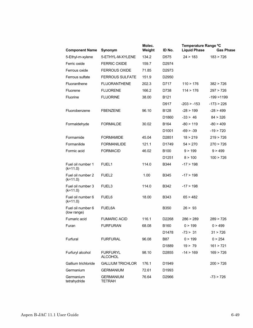
Aspen B-JAC 11.1 User Guide 6-49
Component Name SynonymMolec.Weight ID No.
Temperature Range ºCLiquid Phase Gas Phase
5-Ethyl-m-xylene 5-ETHYL-M-XYLENE 134.2 D575 24 > 183 183 > 726
Ferric oxide FERRIC OXIDE 159.7 D2974
Ferrous oxide FERROUS OXIDE 71.85 D2973
Ferrous sulfate FERROUS SULFATE 151.9 D2950
Fluoranthene FLUORANTHENE 202.3 D717 110 > 176 382 > 726
Fluorene FLUORENE 166.2 D738 114 > 176 297 > 726
Fluorine FLUORINE 38.00 B121 -199 >1199
D917 -203 > -153 -173 > 226
Fluorobenzene FBENZENE 96.10 B128 -28 > 199 -28 > 499
D1860 -33 > 46 84 > 326
Formaldehyde FORMALDE 30.02 B164 -80 > 119 -80 > 409
D1001 -69 > -39 -19 > 720
Formamide FORMAMIDE 45.04 D2851 18 > 219 219 > 726
Formanilide FORMANILIDE 121.1 D1749 54 > 270 270 > 726
Formic acid FORMACID 46.02 B100 9 > 199 9 > 499
D1251 8 > 100 100 > 726
Fuel oil number 1(k=11.0)
FUEL1 114.0 B344 -17 > 198
Fuel oil number 2(k=11.0)
FUEL2 1.00 B345 -17 > 198
Fuel oil number 3(k=11.0)
FUEL3 114.0 B342 -17 > 198
Fuel oil number 6(k=11.0)
FUEL6 18.00 B343 65 > 482
Fuel oil number 6(low range)
FUEL6A B350 26 > 93
Fumaric acid FUMARIC ACID 116.1 D2268 286 > 289 289 > 726
Furan FURFURAN 68.08 B160 0 > 199 0 > 499
D1478 -73 > 31 31 > 726
Furfural FURFURAL 96.08 B87 0 > 199 0 > 254
D1889 19 > 79 161 > 721
Furfuryl alcohol FURFURYLALCOHOL
98.10 D2855 -14 > 169 169 > 726
Gallium trichloride GALLIUM TRICHLOR 176.1 D1949 200 > 726
Germanium GERMANIUM 72.61 D1993
Germaniumtetrahydride
GERMANIUMTETRAH
76.64 D2966 -73 > 726

6-50 Aspen B-JAC 11.1 User Guide
Component Name SynonymMolec.Weight ID No.
Temperature Range ºCLiquid Phase Gas Phase
l-Glutamic acid L-GLUTAMIC ACID 147.1 D5876 396 > 726
Glutaric acid GLUTARIC ACID 132.1 D2281 130 > 322 322 > 726
Glutaric anhydride GLUTARIC ANHYDRI 114.1 D1296 145 > 289 289 > 726
Glutaronitrile GLUTARONITRILE 94.12 D1781 -28 > 285 285 > 526
Glycerine 20 wt % GLYC-20 92.09 B194 -17 > 199
Glycerine 40 wt % GLYC-40 92.09 B195 -17 > 199
Glycerine 60 wt % GLYC-60 92.09 B196 -17 > 199
Glycerol GLYCERIN 92.09 B125 -17 > 315 -17 > 315
D1231 19 > 226 289 > 726
Glyceryl triacetate GLYCERYL TRIACET 218.2 D2370 24 > 248 258 > 726
Glycolic acid GLYCOLIC ACID 76.05 D1887 79 > 169 169 > 726
Glyoxal GLYOXAL 58.04 D1014 14 > 50 50 > 626
Guaiacol GUAIACOL 124.1 D4854 75 > 204 204 > 726
Halothane HALOTHANE 197.4 D2640 -12 > 50 50 > 726
Heavy water HWATER B456 0 > 99
Helium-3 HELIUM 4.00 B183 -149 > 871
D923 -272 > -270
Helium-4 HELIUM-4 4.00 D913 -270 > -268
n-Heptadecane N-HEPTADECANE 240.5 D69 21 > 206 302 > 501
n-Heptadecanoicacid
N-HEPTADECANOIC 270.5 D2265 61 > 206 362 > 726
1-Heptadecanol 1-HEPTADECANOL 256.5 D1145 111 > 301 323 > 726
1-Heptadecene 1-HEPTADECENE 238.5 D281 11 > 300 300 > 726
1-Heptanal 1-HEPTANAL 114.2 D1008 -42 > 56 152 > 726
n-Heptane HEPTANE 100.2 B41 -62 > 239 -62 > 342
D17 -90 > 99 65 > 426
n-Heptanoic acid N-HEPTANOIC ACID 130.2 D2261 -7 > 76 222 > 726
1-Heptanol 1-HEPTANOL 116.2 D1125 -23 > 96 176 > 726
2-Heptanol 2-HEPTANOL 116.2 D1126 20 > 159 159 > 726
2-Heptanone 2-HEPTANONE 114.2 D1063 32 > 150 150 > 726
3-Heptanone 3-HEPTANONE 114.2 D1057 -38 > 147 147 > 726
4-Heptanone 4-HEPTANONE 114.2 D1058 -32 > 143 143 > 726
cis-2-Heptene CIS-2-HEPTENE 98.19 D235 -81 > 78 98 > 726
cis-3-Heptene CIS-3-HEPTENE 98.19 D249 -23 > 95 95 > 726

Aspen B-JAC 11.1 User Guide 6-51
Component Name SynonymMolec.Weight ID No.
Temperature Range ºCLiquid Phase Gas Phase
trans-2-Heptene TRANS-2-HEPTENE 98.19 D236 -109 > 97 97 > 726
trans-3-Heptene TRANS-3-HEPTENE 98.19 D237 -136 > 95 95 > 726
Heptene HEPTENE 98.18 B202 9 > 184 9 > 499
1-Heptene 1-HEPTENE 98.19 D234 -93 > 56 93 > 726
n-Heptylamine N-HEPTYLAMINE 115.2 D2707 30 > 156 156 > 726
n-Heptylbenzene N-HEPTYLBENZENE 176.3 D549 -28 > 246 246 > 726
n-Heptyl mercaptan N-HEPTYL MERCAPT 132.3 D1839 -43 > 176 176 > 726
Hexachlorobenzene
HEXACHLOROBENZEN
284.8 D1575 228 > 309 309 > 726
Hexachloro-1,3-butadiene
HEXACHLORO-1,3-B 260.8 D1561 97 > 208 214 > 724
Hexachlorocyclopentadiene
HEXACHLOROCYCLOP
272.8 D1582 24 > 99 238 > 718
Hexachloroethane HEXACHLOROETHANE
236.7 D1525 186 > 248 186 > 726
n-Hexadecane N-HEXADECANE 226.4 D68 18 > 61 286 > 499
n-Hexadecanoicacid
N-HEXADECANOIC A 256.4 D1272 70 > 209 350 > 726
1-Hexadecanol 1-HEXADECANOL 242.4 D1144 107 > 176 311 > 726
1-Hexadecene 1-HEXADECENE 224.4 D266 4 > 30 284 > 726
cis,trans-2,4-Hexadiene
CIS,TRANS-2,4-HE 82.15 D320 26 > 83 83 > 726
Trans,trans-2,4-Hexadiene
TRANS,TRANS-2,4- 82.15 D314 26 > 81 81 > 726
1,5-Hexadiene 1,5-HEXADIENE 82.15 D310 26 > 59 59 > 726
Hexafluoroacetone HEXAFLUOROACETON
166.0 D2651 -125 > -27 -27 > 726
Hexafluorobenzene HEXAFLUOROBENZEN
186.1 D1864 5 > 76 80 > 326
Hexafluoroethane R116 138.0 B226 -90 > 0 -100 > 399
D2693 -100 > -78 -78 > 426
Hexafluoropropylene
HEXAFLUOROPROPYL
150.0 D1699 -156 > -29 -29 > 726
Hexamethylcyclotrisiloxane
HEXAMETHYLCYCLOT
222.5 D1966 63 > 99 135 > 726
Hexamethyldisilazane
HEXAMETHYLDISILA 161.4 D1964 24 > 125 125 > 726
Hexamethyldisiloxane
HEXAMETHYLDISILO 162.4 D1965 -33 > 100 100 > 726

6-52 Aspen B-JAC 11.1 User Guide
Component Name SynonymMolec.Weight ID No.
Temperature Range ºCLiquid Phase Gas Phase
Hexamethylenediamine
HEXAMETHYLENEDIA
116.2 D1731 56 > 199 199 > 726
Hexamethyleneimine
HEXAMETHYLENEIMI 99.18 D1794 24 > 137 137 > 526
Hexamethylphosphoramide
HEXAMETHYLPHOSP
179.2 D1885
1-Hexanal 1-HEXANAL 100.2 D1009 16 > 128 128 > 726
n-Hexane HEXANE 86.18 B13 -62 > 219 -62 > 332
D11 -95 > 69 65 > 726
1,6-Hexanediol 1,6-HEXANEDIOL 118.2 D1243 242 > 722
Hexanenitrile HEXANENITRILE 97.16 D1786 1 > 163 193 > 703
n-Hexanoic acid N-HEXANOIC ACID 116.2 D1262 1 > 76 205 > 726
1-Hexanol 1-HEXANOL 102.2 D1114 -23 > 46 157 > 726
2-Hexanol 2-HEXANOL 102.2 D1115 -43 > 56 139 > 726
2-Hexanone 2-HEXANONE 100.2 D1062 -52 > 109 127 > 726
3-Hexanone 3-HEXANONE 100.2 D1059 -55 > 123 123 > 726
cis-2-Hexene CIS-2-HEXENE 84.16 D217 -93 > 53 68 > 726
cis-3-Hexene CIS-3-HEXENE 84.16 D219 -137 > 66 66 > 726
trans-2-Hexene TRANS-2-HEXENE 84.16 D218 -53 > 67 67 > 726
trans-3-Hexene TRANS-3-HEXENE 84.16 D220 -113 > 67 67 > 726
1-Hexene HEXENE 84.16 B210 -40 > 199 -40 > 499
D216 -113 > 63 63 > 726
n-Hexyl acetate N-HEXYL ACETATE 144.2 D1363 24 > 171 171 > 726
n-Hexylamine N-HEXYLAMINE 101.2 D2706 18 > 131 131 > 726
n-Hexylbenzene N-HEXYLBENZENE 162.3 D568 -19 > 226 226 > 726
Hexylene glycol HEXYLENE GLYCOL 118.2 D1222 -49 > -33 197 > 726
n-Hexyl mercaptan N-HEXYL MERCAPTA 118.2 D1807 -80 > 152 152 > 726
1-n-Hexylnaphthalene
1-N-HEXYLNAPHTHA 212.3 D714 24 > 176 321 > 726
1-n-Hexyl-1,2,3,4-tetrahydronaphthalene
1-N-HEXYL-1,2,3, 216.4 D716 26 > 304 304 > 726
1-Hexyne 1-HEXYNE 82.15 D413 -73 > 71 71 > 726
2-Hexyne 2-HEXYNE 82.15 D407 26 > 84 84 > 726
3-Hexyne 3-HEXYNE 82.15 D406 26 > 81 81 > 726
Humbletherm 500 HBL500 18.01 B81 65 > 343
Hydracrylonitrile HYDRACRYLONITRIL 71.08 D1764 -46 > 220 220 > 726

Aspen B-JAC 11.1 User Guide 6-53
Component Name SynonymMolec.Weight ID No.
Temperature Range ºCLiquid Phase Gas Phase
Hydrazine HYDRAZIN 32.05 B102 15 > 239 15 > 239
D1717 6 > 113 113 > 723
Hydrazobenzene HYDRAZOBENZENE 184.2 D2783 299 > 726
Hydrochloric acid 30wt %
HCL-30 B351 0 > 121
Hydrogen HYDROGEN 2.02 B5 -249 > -244 -249 >1199
D902 -259 > -240 -23 > 1226
Hydrogen bromide HBR 80.92 B214 -75 > 74 -199 > 799
D1906 -87 > -66 -66 > 326
Hydrogen chloride HCL 36.46 B9 -100 > 49 -80 > 499
D1904 0 > -88 -73 > 726
Hydrogen cyanide HCN 27.03 B68 0 > 139 0 > 149
D1771 -13 > 25 26 > 151
Hydrogen fluoride HF 20.00 B221 19 > 121 19 > 799
D1905 -78 > 19 76 > 176
Hydrogen iodide HI 127.9 B216 34 > 149 34 > 799
D1907 -47 > -35 -23 > 376
Hydrogen peroxide HYDPEROX 34.01 B334 0 > 449 0 > 1199
D1996 0 > 150 99 > 326
Hydrogen selenide HYDROGEN SELENID 80.98 D3951 -42 > 726
Hydrogen sulfide H2S 34.08 B83 -73 > 93 -73 > 499
D1922 -79 > -3 -23 > 206
p-Hydroquinone P-HYDROQUINONE 110.1 D1186 171 > 284 284 > 726
p-Hydroxybenzaldehyde
P-HYDROXYBENZALD
122.1 D1043 148 > 309 309 > 726
Hydroxycaproicacid
HYDROXYCAPROICA
132.2 D5882 105 > 285 302 > 726
2-Hydroxyethylacrylate
2-HYDROXYETHYL A 116.1 D6883 57 > 209 209 > 726
Hydroxylamine HYDROXYLAMINE 33.03 D4886 109 > 726
8-Hydroxyquinoline 8-HYDROXYQUINOLI 145.2 D5871 266 > 726
Hypophosphorousacid
HYPOPHOSPHOROUS
66.00 D1909
Indane INDANE 118.2 D820 -23 > 169 177 > 726
Indene INDENE 116.2 D803 -1 > 126 182 > 722
Indole INDOLE 117.1 D2784 52 > 226 252 > 726

6-54 Aspen B-JAC 11.1 User Guide
Component Name SynonymMolec.Weight ID No.
Temperature Range ºCLiquid Phase Gas Phase
Inositol INOSITOL 180.2 D1249
Component Name SynonymMolec.Weight ID No.
Temperature Range ºCLiquid Phase Gas Phase
Iodine IODINE 253.8 B224 121 > 499 0 > 799
D1998 113 > 476
Iodobenzene IODOBENZENE 204.0 D1691 -23 > 76 188 > 726
Iron IRON 55.85 D2923
Isobutane IBUTANE 58.12 B99 -40 > 99 -40 > 237
D4 -83 > 101 -11 > 426
Isobutanol IBUTANOL 74.12 B62 -40 > 199 -40 > 339
D1106 -62 > 107 107 > 726
Isobutene IBUTYLEN 56.10 B211 -40 > 104 -40 > 499
D207 -140 > -6 -6 > 726
Isobutyl acetate ISOBUTYL ACETATE 116.2 D1316 16 > 70 116 > 226
Isobutyl acrylate ISOBUTYL ACRYLAT 128.2 D2384 20 > 131 131 > 726
Isobutylamine ISOBUTYLAMINE 73.14 D1714 -23 > 67 67 > 726
Isobutylbenzene ISOBUTYLBENZENE 134.2 D519 -51 > 172 172 > 726
Isobutyl formate ISOBUTYL FORMATE 102.1 D1305 16 > 98 98 > 726
Isobutyl isobutyrate ISOBUTYL ISOBUTY 144.2 D1360 -23 > 147 147 > 726
Isobutyl mercaptan ISOBUTYL MERCAPT 90.19 D1805 -144 > 88 88 > 726
Isobutyric acid IBUTACID 88.11 B312 -17 > 176 -17 > 499
D1260 -23 > 154 154 > 726
Isobutyronitrile ISOBUTYRONITRILE 69.11 D1787 -71 > 103 103 > 703
Isopentane IPENTANE 72.15 B103 -62 > 97 -62 > 499
D8 -123 > 36 0 > 726
Isopentyl acetate ISOPENTYL ACETAT 130.2 D1317 -3 > 142 142 > 526
Isopentylisovalerate
ISOPENTYL ISOVAL 172.3 D1361 26 > 193 193 > 726
Isophorone ISOPHORONE 138.2 D1077 -8 > 146 215 > 726
Isophthalic acid ISOPHTHALIC ACID 166.1 D1288 345 > 479 479 > 726
Isophthaloylchloride
ISOPHTHALOYL CHL 203.0 D2899 275 > 726
Isoprene ISOPRENE 68.11 B212 -40 > 114 -40 > 499
D309 0 > 34 34 > 726
Isopropanol IPOH 60.09 B45 -40 > 199 -40 > 499
D1104 -85 > 82 82 > 726

Aspen B-JAC 11.1 User Guide 6-55
Component Name SynonymMolec.Weight ID No.
Temperature Range ºCLiquid Phase Gas Phase
Isopropyl acetate IPACETAT 102.1 B148 -40 > 199 -40 > 499
D1319 -57 > 88 88 > 726
Isopropylamine IPAMINE 59.11 B101 -62 > 159 -62 > 499
D1719 0 > 32 32 > 726
Isopropyl chloride ISOPROPYL CHLORI 78.54 D1530 -23 > 35 35 > 726
Isopropylcyclohexane
ISOPROPYLCYCLOHE
126.2 D150 -89 > 154 154 > 726
Isopropyl iodide ISOPROPYL IODIDE 170.0 D1684 -48 > 89 89 > 726
Isopropylmercaptan
ISOPROPYL MERCAP 76.16 D1810 -14 > 52 52 > 726
Isoquinoline ISOQUINOLINE 129.2 D2785 29 > 243 243 > 726
Isovaleric acid ISOVALERIC ACID 102.1 D1261 26 > 175 175 > 726
Itaconic acid ITACONIC ACID 130.1 D2278 165 > 327 327 > 726
Ketene KETENE 42.04 D1100 -88 > -49 -49 > 726
Krypton KRYPTON 83.80 B285 -149 > 449
D920
Lactic acid LACTIC ACID 90.08 D5880 17 > 181 181 > 726
Lactonitrile LACTONITRILE 71.08 D5872 48 > 183 183 > 726
Levulinic acid LEVULINIC ACID 116.1 D4852 34 > 245 245 > 726
d-Limonene D-LIMONENE 136.2 D290 20 > 176 176 > 726
Linoleic acid LINOLEIC ACID 280.5 D1280 -5 > 354 354 > 726
Linolenic acid LINOLENIC ACID 278.4 D2255 116 > 176 358 > 726
Lithium LITHIUM 6.94 D2924 180 >1346
Lysine LYSINE 146.2 D5873 224 > 337 341 > 726
Magnesium nitrate MAGNESIUM NITRAT 148.3 D3953
Magnesium oxide MAGNESIUM OXIDE 40.30 D2951
Magnesium sulfate MAGNESIUM SULFAT 120.4 D2952
Malathion MALATHION 330.4 D3887
Maleic acid MALEIC ACID 116.1 D1286 130 > 291 291 > 726
Maleic anhydride MALEIC ANHYDRIDE 98.06 D1298 52 > 201 201 > 726
Malic acid MALIC ACID 134.1 D4853 129 > 307 328 > 726
Malonic acid MALONIC ACID 104.1 D3268 134 > 306 306 > 726
Malononitrile MALONONITRILE 66.06 D1785 31 > 218 218 > 726
Marlotherm s MARLO-S 272.0 B321 19 > 379
L-Menthol L-MENTHOL 156.3 D1159 42 > 216 216 > 726

6-56 Aspen B-JAC 11.1 User Guide
Component Name SynonymMolec.Weight ID No.
Temperature Range ºCLiquid Phase Gas Phase
2-Mercaptoethanol 2-MERCAPTOETHANO
78.13 D6858 41 > 157 157 > 726
3-Mercaptopropionicacid
3-MERCAPTOPROPIO
106.1 D1873 17 > 86 227 > 726
Mercury MERCURY 200.6 D2930 -38 > 356
Mesitylene MESITYL 120.2 B279 -37 > 159 -128 > 537
D516 15 > 76 164 > 476
Mesityl oxide MESITYL OXIDE 98.14 D1065 19 > 129 129 > 719
Methacrolein METHACROLEIN 70.09 D1037 -8 > 67 67 > 726
2-methacrylamide 2-METHACRYLAMIDE 85.11 D1878 110 > 214 214 > 726
Methacrylic acid METHACRYLIC ACID 86.09 D1278 14 > 160 160 > 726
Methacrylonitrile METHACRYLONITRIL 67.09 D1775 24 > 90 90 > 726
Methane METHANE 16.04 B86 -181 > -90 -128 > 648
D1 -182 > -103 -176 > 576
Methanesulfonicacid
METHANESULFONIC 96.11 D4874
Methanol METHANOL 32.04 B14 -51 > 204 -51 > 204
D1101 -97 > 64 0 > 726
Methanol 20 wt % MEOH-20 18.02 B30 -6 > 119
Methanol 40 wt % MEOH-40 18.02 B31 -28 > 119
Methanol 60 wt % MEOH-60 16.80 B455 -51 > 9
Methoxyacetic acid METHOXYACETIC AC 90.08 D4875 72 > 205 205 > 626
2-Methoxyethanol 2-METHOXYETHANOL
76.10 D2860 124 > 726
2-2-Methoxyethoxyethanol
2-(2-METHOXYETHO 120.1 D2863 24 > 126 193 > 726
p-Methoxyphenol P-METHOXYPHENOL 124.1 D2859 105 > 242 242 > 726
3-Methoxypropionitrile
3-METHOXYPROPION
85.11 D5890 45 > 165 165 > 726
n-Methylacetamide N-METHYLACETAMID 73.09 D6854 85 > 204 204 > 726
Methyl acetate MACETATE 74.08 B129 -62 > 159 -62 > 499
D1312 -19 > 100 56 > 526
Methylacetoacetate
METHYLACETOACET
116.1 D5886 0 > 199 171 > 726

Aspen B-JAC 11.1 User Guide 6-57
Component Name SynonymMolec.Weight ID No.
Temperature Range ºCLiquid Phase Gas Phase
Methylacetylene MACETYL 40.06 B152 -100 > 99 -100 > 499
D402 -73 > -23 -23 > 526
Methyl acrylate MACRYLAT 86.09 B150 0 > 239 0 > 499
D1341 1 > 80 80 > 726
Methylal METHYLAL 76.10 D1431 -104 > 36 41 > 701
Methylamine MAMINE 31.06 B188 -60 > 119 -60 > 499
D1701 -93 > -6 -6 > 376
n-Methylaniline N-METHYLANILINE 107.2 D1795 -23 > 195 195 > 726
Methyl benzoate METHYL BENZOATE 136.1 D1390 14 > 199 199 > 726
2-Methylbenzofuran 2-METHYLBENZOFUR
132.2 D1485 197 > 726
Methyl bromide MBROMIDE 94.95 B134 -80 > 159 -80 > 499
D1641 -88 > 3 0 > 551
3-Methyl-1,2-butadiene
3-METHYL-1,2-BUT 68.12 D311 -113 > 40 40 > 726
2-Methyl-1-butanol MBUTANOL 88.15 D1112 0 > 128 128 > 726
2-Methyl-2-butanol 2-METHYL-2-BUTAN 88.15 D1111 -8 > 101 101 > 726
3-Methyl-1-butanol 3-METHYL-1-BUTAN 88.15 D1123 131 > 726
3-Methyl-2-butanol 3-METHYL-2-BUTAN 88.15 D1124 11 > 111 111 > 726
2-Methyl-1-butene MBUTENE 70.13 D212 -133 > 22 31 > 721
2-Methyl-2-butene 2-METHYL-2-BUTEN 70.13 D214 -133 > 26 38 > 718
3-Methyl-1-butene 3-METHYL-1-BUTEN 70.13 D213 0 > 20 90 > 720
2-Methyl-1-butene-3-yne
MBUTENEYNE 66.10 D414 24 > 32 32 > 726
Methyl sec-butylether
METHYL SEC-BUTYL 88.15 D1426 -24 > 58 58 > 726
Methyl tert-butylether
MTBE 88.15 B463 -73 > 54 -73 > 232
D1405 -93 > 55 0 > 726
Methyl-n-butyl-ether
METHYL-N-BUTYL-E 88.15 D1413 -115 > 70 26 > 726
3-Methyl-1-butyne 3-METHYL-1-BUTYN 68.12 D419 -73 > 26 28 > 726
Methyl n-butyrate METHYL N-BUTYRAT 102.1 D1332 24 > 102 102 > 726
2-Methylbutyricacid
2-METHYLBUTYRIC 102.1 D1257 83 > 176 176 > 726
Methyl chloride MCHLORID 50.50 B118 -40 > 99 -60 > 299
D1502 -24 > 76 -43 > 426

6-58 Aspen B-JAC 11.1 User Guide
Component Name SynonymMolec.Weight ID No.
Temperature Range ºCLiquid Phase Gas Phase
Methylchloroacetate
METHYLCHLOROACE
108.5 D5866 26 > 129 129 > 726
Methylchloroformate
METHYLCHLOROFOR
94.50 D4876 -10 > 70 70 > 626
Methyl chlorosilane METHYL CHLOROSIL 80.59 D3935 -23 > 8 8 > 726
Methylcyanoacetate
METHYLCYANOACET
99.09 D5888 -13 > 205 205 > 726
Methylcyclohexane MCHEXANE 98.19 B267 -73 > 96 -73 > 426
D138 0 > 46 100 > 726
cis-2-Methylcyclohexanol
CIS-2-METHYLCYCL 114.2 D1153 36 > 126 164 > 726
cis-3-Methylcyclohexanol
CIS-3-METHYLCYCL 114.2 D1155 15 > 47 167 > 726
cis-4-Methylcyclohexanol
CIS-4-METHYLCYCL 114.2 D1157 36 > 170 170 > 726
trans-2-Methylcyclohexanol
TRANS-2-METHYLCY 114.2 D1154 6 > 51 166 > 726
trans-3-Methylcyclohexanol
TRANS-3-METHYLCY 114.2 D1156 15 > 47 167 > 726
trans-4-Methylcyclohexanol
TRANS-4-METHYLCY 114.2 D1158 36 > 170 170 > 726
1-Methylcyclohexanol
1-METHYLCYCLOHEX
114.2 D1152 25 > 186 156 > 726
n-Methylcyclohexylamine
N-METHYLCYCLOHEX
113.2 D2731 37 > 148 148 > 726
Methylcyclopentadiene
METHYLCYCLOPENTA
80.13 D312 26 > 72 72 > 726
Methylcyclopentane
MCPENTAN 84.16 B284 -76 > 58 -73 > 426
D105 -24 > 71 71 > 726
Methyldichlorosilane
METHYL DICHLOROS 115.0 D3936 1 > 41 41 > 726
Methyldiethanolamine
METHYL DIETHANOL 119.2 D1722 65 > 225 246 > 726
Methyldiethanolamine 50 wt %
MDEA-50 B434 0 > 104
Methyldodecanoate
METHYLDODECANOA
214.3 D2385 82 > 252 266 > 726
1-Methyl-1,4-ehtylbenzene
MEBENZ4 120.2 B278 -51 > 148 -128 > 537

Aspen B-JAC 11.1 User Guide 6-59
Component Name SynonymMolec.Weight ID No.
Temperature Range ºCLiquid Phase Gas Phase
Methylethanolamine
METHYLETHANOLAMI
75.11 D6862 41 > 157 157 > 726
1-Methyl-1,2,ethylbenzene
MEBENZ2 120.2 B295 -51 > 159 -128 > 537
1-Methyl-1,3-ethylbenzene
MEBENZ3 120.2 B277 -56 > 138 -128 > 537
1-Methyl-1-ethylcyclopentane
1-METHYL-1-ETHYL 112.2 D116 24 > 121 121 > 726
Methyl ethyl ether METHYL ETHYL ETH 60.10 D1407 -54 > 7 0 > 726
Methyl ethyl ketone MEK 72.10 B61 -62 > 201 -62 > 304
D1052 -86 > 79 79 > 726
2-Methyl-3-ethylpentane
2-METHYL-3-ETHYL 114.2 D38 -114 > 115 115 > 726
3-Methyl-3-ethylpentane
3-METHYL-3-ETHYL 114.2 D39 -71 > 108 118 > 726
Methyl ethyl sulfide METHS 76.16 B327 -17 > 93 -17 > 371
Methyl fluoride METHYL FLUORIDE 34.03 D1613 -141 > -78 -78 > 726
n-Methylformamide N-METHYLFORMAMID
59.07 D2852 24 > 199 199 > 726
Methyl formate MFORMATE 60.05 B358 -20 > 99 0 > 499
D1301 -23 > 31 26 > 726
Methylglutaronitrile METHYLGLUTARONIT
108.1 D2798 97 > 262 262 > 526
2-Methylheptane MHEPTANE 114.2 B223 -40 > 148 -40 > 499
D28 -106 > 117 117 > 726
3-Methylheptane 3-METHYLHEPTANE 114.2 D29 -104 > 118 118 > 726
4-Methylheptane 4-METHYLHEPTANE 114.2 D30 -33 > 86 117 > 726
2-Methylhexanal 2-METHYLHEXANAL 114.2 D1016 26 > 142 142 > 726
3-Methylhexanal 3-METHYLHEXANAL 114.2 D1017 26 > 142 142 > 726
2-Methylhexane IHEPTANE 100.2 B207 -40 > 159 -40 > 499
D18 0 > 90 90 > 720
3-Methylhexane MHEXANE 100.2 B266 -73 > 82 -73 > 426
D19 -119 > 91 91 > 721
5-Methyl-1-hexanol 5-METHYL-1-HEXAN 116.2 D1129 26 > 171 171 > 726
5-Methyl-2-hexanone
5-METHYL-2-HEXAN 114.2 D1064 -73 > 144 144 > 726
2-Methyl-1-hexene 2-METHYL-1-HEXEN 98.19 D238 24 > 91 91 > 726
3-Methyl-1-hexene 3-METHYL-1-HEXEN 98.19 D240 24 > 83 83 > 726

6-60 Aspen B-JAC 11.1 User Guide
Component Name SynonymMolec.Weight ID No.
Temperature Range ºCLiquid Phase Gas Phase
4-Methyl-1-hexene 4-METHYL-1-HEXEN 98.19 D226 -141 > 86 86 > 726
1-Methylindene 1-METHYLINDENE 130.2 D723 198 > 726
2-Methylindene 2-METHYLINDENE 130.2 D724 184 > 726
Methyl iodide METHYL IODIDE 141.9 D1681 -19 > 35 26 > 726
Methyl isobutylether
METHYL ISOBUTYL 88.15 D1410 26 > 58 58 > 726
Methyl isobutylketone
MIBK 100.2 B169 -80 > 159 0 > 499
D1054 24 > 116 116 > 726
Methyl isocyanate METHYL ISOCYANAT 57.05 D2793 38 > 726
Methyl isopropenylketone
METHYL I-KETONE 84.12 D1096 26 > 97 97 > 726
Methyl isopropylether
METHYL IE 74.12 D1411 -145 > 30 30 > 726
Methyl isopropylketone
METHYL IK 86.13 D1061 -92 > 94 94 > 726
Methyl mercaptan MMERCAPT 48.10 B167 -80 > 149 -80 > 499
D1801 5 > 326
Methylmethacrylate
MMACRYL 100.1 B54 0 > 159 0 > 499
D1351 16 > 90 100 > 726
1-Methylnaphthalene
1-METHYLNAPHTHAL 142.2 D702 -30 > 126 244 > 726
2-Methylnaphthalene
2-METHYLNAPHTHAL 142.2 D703 34 > 176 241 > 726
2-Methylnonane 2-METHYLNONANE 142.3 D86 -74 > 166 166 > 726
3-Methylnonane 3-METHYLNONANE 142.3 D85 -84 > 167 167 > 726
4-Methylnonane 4-METHYLNONANE 142.3 D87 -98 > 165 165 > 726
5-Methylnonane 5-METHYLNONANE 142.3 D88 -87 > 165 165 > 726
8-Methyl-1-nonanol 8-METHYL-1-NONAN 158.3 D1139 -33 > 219 219 > 726
2-Methyloctane 2-METHYLOCTANE 128.3 D91 -80 > 143 143 > 726
3-Methyloctane 3-METHYLOCTANE 128.3 D92 -66 > 133 144 > 726
4-Methyloctane 4-METHYLOCTANE 128.3 D93 -50 > 142 142 > 726
Methyl oleate METHYL OLEATE 296.5 D1362 19 > 336 343 > 726
2-Methylpentane ISOHEXANE 86.17 B215 -40 > 199 -40 > 499
D12 -15 > 60 60 > 720

Aspen B-JAC 11.1 User Guide 6-61
Component Name SynonymMolec.Weight ID No.
Temperature Range ºCLiquid Phase Gas Phase
3-Methylpentane MPENTANE 86.18 B281 -59 > 39 -59 > 426
D13 -7 > 63 63 > 723
2-Methyl-1-pentanol
2-METHYL-1-PENTA 102.2 D1117 31 > 147 147 > 726
4-Methyl-2-pentanol
4-METHYL-2-PENTA 102.2 D1130 30 > 131 131 > 726
3-Methyl-2-pentanone
3-METHYL-2-PENTA 100.2 D1055 24 > 117 117 > 726
2-Methyl-1-pentene 2-METHYL-1-PENTE 84.16 D221 -43 > 56 62 > 726
2-Methyl-2-pentene 2-METHYL-2-PENTE 84.16 D224 -135 > 67 67 > 726
3-Methyl-cis-2-pentene
3-METHYL-CIS-2-P 84.16 D225 -134 > 67 67 > 726
3-Methyl-1-pentene 3-METHYL-1-PENTE 84.16 D222 -152 > 54 54 > 726
4-Methyl-cis-2-pentene
4-METHYL-CIS-2-P 84.16 D227 -134 > 56 56 > 726
4-Methyl-trans-2-pentene
4-METHYL-TRANS-2 84.16 D228 -140 > 58 58 > 726
4-Methyl-1-pentene 4-METHYL-1-PENTE 84.16 D223 -153 > 53 53 > 723
Methyl tert-pentylether
METHYL TERT-PENT 102.2 D1427 -6 > 86 86 > 726
Methyl-n-pentylether
METHYL-N-PENTYL 102.2 D1429 24 > 98 98 > 726
2-Methylpropanal 2-METHYLPROPANAL
72.11 D1006 24 > 64 64 > 726
Methyl propionate METHYL PROPIONAT 88.11 D1322 26 > 79 76 > 726
Methyl-n-propylether
METHYL-N-PROPYL 74.12 D1408 -139 > 39 39 > 726
Methyl propylketone
MPK 86.13 B353 0 > 93 0 > 499
2-Methylpyridine 2-METHYLPYRIDINE 93.13 D1797 -53 > 129 129 > 726
3-Methylpyridine 3-METHYLPYRIDINE 93.13 D2797 19 > 59 144 > 726
4-Methylpyridine 4-METHYLPYRIDINE 93.13 D2799 3 > 145 145 > 726
n-Methylpyrrole N-METHYLPYRROLE 81.12 D1754 -56 > 112 112 > 726
n-Methylpyrrolidine N-METHYLPYRROLID 85.15 D1767 -23 > 79
n-Methyl-2-pyrrolidone
N-METHYL-2-PYRRO 99.13 D1071 33 > 203 203 > 726
Methyl salicylate METHYL SALICYLAT 152.1 D1373 22 > 223 220 > 726
Methyl silane METHYL SILANE 46.14 D3984 -56 > 726

6-62 Aspen B-JAC 11.1 User Guide
Component Name SynonymMolec.Weight ID No.
Temperature Range ºCLiquid Phase Gas Phase
alpha-Methylstyrene
MSTYRENE 118.2 B318 -2 > 199 -17 > 499
D613 -23 > 165 165 > 726
m-Methylstyrene M-METHYLSTYRENE 118.2 D603 -73 > 171 171 > 726
o-Methylstyrene O-METHYLSTYRENE 118.2 D602 -68 > 169 169 > 726
p-Methylstyrene P-METHYLSTYRENE 118.2 D612 -20 > 172 172 > 726
3-Methyl sulfolane 3-METHYL SULFOLA 134.2 D1847 16 > 176 275 > 726
Methyltrichlorosilane
METHYL TRICHLORO 149.5 D3937 -48 > 26 66 > 726
Methyl vinyl ether MVE 58.08 B448 -10 > 82 -10 > 121
D1470 -122 > 5 26 > 726
Mobiltherm light MBLLIGHT 18.01 B323 9 > 343
Mobiltherm 600 MBL600 18.01 B80 37 > 287
Mobiltherm 603 MBL603 18.01 B324 9 > 287
Mobiltherm 605 MBL605 18.01 B322 37 > 315
Monochlorobenzene
MCB 112.6 B8 -28 > 199 -28 > 231
D1571 -23 > 86 126 > 726
Monochlorotoluene MCLTOL 112.5 B310 7 > 159
Monoethanolamine MEA 61.08 B333 18 > 179 18 > 499
D1723 24 > 169 169 > 726
Monoethanolamine20 wt %
MEA-20 18.01 B33 9 > 99
Monoethanolamine40 wt %
MEA-40 18.01 B34 9 > 99
Monoethanolamine60 wt %
MEA-60 18.01 B35 9 > 99
Morpholine MORPHOLINE 87.12 D1765 6 > 127 127 > 726
Naphthalene NAPHTHAL 128.2 B237 99 > 459 0 > 799
D701 80 > 217 217 > 726
Natural gas(sp.gr.=0.71)
NG1 20.46 B303 -17 > 482
Natural gas(sp.gr.=0.80)
NG36 23.71 B304 -17 > 482
Natural gas fluegas
NGFG 27.78 B206 99 > 899
Neon NEON 20.18 B184 -149 >1093
D919 -248 > -233

Aspen B-JAC 11.1 User Guide 6-63
Component Name SynonymMolec.Weight ID No.
Temperature Range ºCLiquid Phase Gas Phase
Neopentane NEOPENT 72.15 B275 -17 > 9 -17 > 279
D9 -16 > 9 9 > 151
Neopentanoic acid NEOPENTANOIC ACI 102.1 D2258 42 > 163 163 > 726
Neopentyl glycol NEOPENTYLGLYCOL
104.1 D1214 126 > 209 209 > 726
Nitric acid NITRIC ACID 63.01 D1903 0 > 29 82 > 726
Nitric acid 20 wt % HNO3-20 18.00 B230 0 > 93
Nitric acid 40 wt % HNO3-40 18.00 B231 0 > 93
Nitric acid 60 wt % HNO3-60 18.00 B98 0 > 93
Nitric oxide NO 30.01 B120 -183 > 499
D912 -163 > -123 -151 > 476
m-Nitroaniline M-NITROANILINE 138.1 D2782 113 > 305
o-Nitroaniline O-NITROANILINE 138.1 D2780 71 > 284
p-Nitroaniline P-NITROANILINE 138.1 D2781 147 > 335
o-Nitroanisole O-NITROANISOLE 153.1 D1891 89 > 134
Nitrobenzene NITROBEN 123.1 B305 -17 > 209 -17 > 599
D1886 5 > 126 210 > 726
3-Nitrobenzotrifluoride
3-NITROBENZOTRIF 191.1 D4863 202 > 726
o-Nitrodiphenylamine
O-NITRODIPHENYLA 214.2 D2738 342 > 726
Nitroethane NETHANE 75.07 B239 0 > 279 0 > 499
D1761 -73 > 114 114 > 726
Nitrogen NITROGEN 28.01 B4 -204 > -151 -204 > 982
D905 -209 > -161 -209 >1226
Nitrogen dioxide NO2 46.01 B341 -9 > 149 -9 > 1399
D900 -3 > 16 26 > 726
Nitrogen pentoxide NITROGEN PENTOXI 108.0 D1944
Nitrogen tetroxide NITROGEN TETROXI 92.01 D906
Nitrogen trichloride NITROGEN TRICHLO 120.4 D2921 70 > 726
Nitrogen trifluoride NITROGEN TRIFLUO 71.00 D1972 -129 > 726
Nitrogen trioxide NITROGEN TRIOXID 76.01 D904
Nitroglycerine NITROGLYCERINE 227.1 D2779
Nitromethane NMETHANE 61.04 B67 0 > 199 0 > 229
D1760 -28 > 101 101 > 726

6-64 Aspen B-JAC 11.1 User Guide
Component Name SynonymMolec.Weight ID No.
Temperature Range ºCLiquid Phase Gas Phase
1-Nitropropane 1-NITROPROPANE 89.09 D1762 -33 > 131 131 > 726
2-Nitropropane 2-NITROPROPANE 89.09 D1763 -23 > 120 120 > 726
Nitrosyl chloride NITROSYL CHLORID 65.46 D1986 -5 > 726
m-Nitrotoluene M-NITROTOLUENE 137.1 D1780
o-Nitrotoluene O-NITROTOLUENE 137.1 D1778
p-Nitrotoluene P-NITROTOLUENE 137.1 D1779
Nitrous oxide N2O 44.01 B122 -100 > 29 -100 > 1315
D899 -90 > 726
n-Nonadecane N-NONADECANE 268.5 D71 32 > 329 329 > 501
Nonadecanoic acid NONADECANOIC ACI 298.5 D2266 71 > 331 385 > 726
1-Nonadecanol 1-NONADECANOL 284.5 D1149 118 > 344 344 > 726
1-Nonadecene 1-NONADECENE 266.5 D283 24 > 329 329 > 726
1-Nonanal 1-NONANAL 142.2 D1011 46 > 194 194 > 726
n-Nonane NONANE 128.3 B259 -45 > 232 -128 > 537
D46 -53 > 66 150 > 726
n-Nonanoic acid N-NONANOIC ACID 158.2 D1259 12 > 126 255 > 726
1-Nonanol 1-NONANOL 144.3 D1134 6 > 146 213 > 726
2-Nonanol 2-NONANOL 144.3 D1135 38 > 188 198 > 726
2-Nonanone 2-NONANONE 142.2 D1074 -7 > 194 194 > 726
5-Nonanone 5-NONANONE 142.2 D1073 -4 > 188 188 > 726
1-Nonene NONENE 126.2 B425 26 > 204 26 > 204
D259 -53 > 146 146 > 726
n-Nonylamine N-NONYLAMINE 143.3 D2709 50 > 202 202 > 726
n-Nonylbenzene N-NONYLBENZENE 204.4 D570 -3 > 282 282 > 726
n-Nonyl mercaptan N-NONYL MERCAPTA 160.3 D1808 67 > 219 219 > 726
1-n-Nonylnaphthalene
1-N-NONYLNAPHTHA 254.4 D711 10 > 365 365 > 726
Nonylphenol NONYLPHENOL 220.4 D1199 105 > 285 307 > 726
2-Norbornene 2-NORBORNENE 94.16 D823 46 > 95 95 > 726
n-Octadecane N-OCTADECANE 254.5 D70 28 > 166 316 > 501
1-Octadecanol 1-OCTADECANOL 270.5 D1146 115 > 206 334 > 726
1-Octadecene 1-OCTADECENE 252.5 D267 17 > 166 314 > 726
Octafluoro-2-butene
OCTAFLUORO-2-BUT 200.0 D2653 -2 > -2 24 > 726
Octafluorocyclobutane
OCTAFLUOROCYCLOB
200.0 D2654 -28 > -3 -5 > 326

Aspen B-JAC 11.1 User Guide 6-65
Component Name SynonymMolec.Weight ID No.
Temperature Range ºCLiquid Phase Gas Phase
Octafluoropropane OCTAFLUOROPROPAN
188.0 D2652 -147 > -36 0 > 726
Octamethylcyclotetrasiloxane
OCTAMETHYLCYCLOT
296.6 D1988 17 > 174 174 > 726
1-Octanal 1-OCTANAL 128.2 D1010 37 > 173 173 > 726
n-Octane OCTANE 114.2 B29 -40 > 239 -40 > 344
D27 -56 > 101 76 > 476
n-Octanoic acid N-OCTANOIC ACID 144.2 D1265 16 > 146 239 > 726
1-Octanol 1-OCTANOL 130.2 D1132 6 > 151 195 > 726
2-Octanol 2-OCTANOL 130.2 D1133 26 > 179 179 > 726
2-Octanone 2-OCTANONE 128.2 D1083 -20 > 172 172 > 726
trans-2-Octene TRANS-2-OCTENE 112.2 D251 -71 > 117 124 > 726
trans-3-Octene TRANS-3-OCTENE 112.2 D277 -33 > 123 123 > 726
trans-4-Octene TRANS-4-OCTENE 112.2 D279 -23 > 122 122 > 726
Octene OCTENE 112.2 B208 -40 > 259 -40 > 499
1-Octene 1-OCTENE 112.2 D250 -73 > 41 121 > 526
n-Octylamine N-OCTYLAMINE 129.2 D2708 40 > 179 179 > 726
n-Octylbenzene N-OCTYLBENZENE 190.3 D569 -15 > 264 264 > 726
n-Octyl formate N-OCTYL FORMATE 158.2 D1308 24 > 198 198 > 726
n-Octyl mercaptan N-OCTYL MERCAPTA 146.3 D1809 58 > 199 199 > 726
tert-Octylmercaptan
TERT-OCTYL MERCA 146.3 D1838 40 > 155 155 > 726
p-tert-Octylphenol P-TERT-OCTYLPHEN 206.3 D2195 109 > 290 290 > 726
Oil flue gas OFG 29.20 B205 99 > 899
Oil SAE 10 LUBSAE10 86.17 B32 4 > 119
Oil SAE 20 LUBSAE20 86.17 B376 9 > 93
Oil SAE 30 LUBSAE30 86.17 B53 4 > 119
Oil SAE 40 LUBSAE40 86.17 B52 4 > 121
Oil SAE 50 LUBSAE50 86.17 B377 9 > 93
Oil - Turbine 150SSU light
TURBOIL 18.01 B135 4 > 104
Oleic acid OLEIC ACID 282.5 D1279 24 > 147 359 > 726
Oxalic acid OXALIC ACID 90.04 D1255 295 > 726
Oxazole OXAZOLE 69.06 D5869 69 > 726
Oxygen OXYGEN 32.00 B84 -199 > -125 -199 >1099
D901 -213 > -131 -193 >1226

6-66 Aspen B-JAC 11.1 User Guide
Component Name SynonymMolec.Weight ID No.
Temperature Range ºCLiquid Phase Gas Phase
Ozone OZONE 48.00 D924 -183 > -128 -111 > 76
Palm oil PALMOIL 18.01 B316 9 > 229
Paraldehyde PARALDEHYDE 132.2 D1050 29 > 71 124 > 724
Patassiumcaronate 30 wt %
K2CO3-30 B445 9 > 93
Pentachloroethane PENTACHLOROETHAN
202.3 D1590 59 > 159 159 > 726
n-Pentadecane N-PENTADECANE 212.4 D67 19 > 51 270 > 499
Pentadecanoic acid PENTADECANOIC AC 242.4 D2259 56 > 299 338 > 726
1-Pentadecanol 1-PENTADECANOL 228.4 D1143 43 > 72 299 > 726
1-Pentadecene 1-PENTADECENE 210.4 D265 14 > 268 268 > 726
cis-1,3-Pentadiene CIS-1,3-PENTADIE 68.12 D305 -86 > 44 44 > 726
trans-1,3-Pentadiene
TRANS-1,3-PENTAD 68.12 D306 -51 > 42 42 > 726
1,2-Pentadiene 1,2-PENTADIENE 68.12 D304 -65 > 44 44 > 726
1,4-Pentadiene 1,4-PENTADIENE 68.12 D307 -145 > 25 25 > 726
2,3-Pentadiene 2,3-PENTADIENE 68.12 D308 -125 > 48 48 > 726
Pentaerythritol PE 136.1 D1246 260 > 350 357 > 717
Pentaerythritoltetranitrate
PETN 316.1 D2778
Pentafluoroethane PENTAFLUOROETHAN
120.0 D1646 -102 > -47 -47 > 726
1-Pentanal 1-PENTANAL 86.13 D1007 10 > 102 102 > 726
n-Pentane PENTANE 72.15 B79 -40 > 159 -40 > 499
D7 -129 > 36 26 > 726
1,5-Pentanediol 1,5-PENTANEDIOL 104.1 D1242 -16 > 106 238 > 718
n-Pentanoic acid N-PENTANOIC ACID 102.1 D1258 -3 > 56 185 > 726
1-Pentanol 1-PENTANOL 88.15 D1109 0 > 79 137 > 717
2-Pentanol 2-PENTANOL 88.15 D1110 2 > 118 118 > 726
3-Pentanol 3-PENTANOL 88.15 D1120 0 > 115 115 > 726
2-Pentanone 2-PENTANONE 86.13 D1060 -23 > 90 102 > 722
3-Pentanone DEK 86.13 B213 -40 > 119 -40 > 799
D1053 0 > 76 0 > 726
cis-2-Pentene CIS-2-PENTENE 70.13 D210 -151 > 36 36 > 726
trans-2-Pentene TRANS-2-PENTENE 70.13 D211 -140 > 36 36 > 726
1-Pentene 1-PENTENE 70.13 D209 -153 > 29 29 > 526

Aspen B-JAC 11.1 User Guide 6-67
Component Name SynonymMolec.Weight ID No.
Temperature Range ºCLiquid Phase Gas Phase
1-Pentene-3-yne 1-PENTENE-3-YNE 66.10 D420 24 > 59 59 > 726
1-Pentene-4-yne 1-PENTENE-4-YNE 66.10 D421 24 > 42 42 > 726
n-Pentyl acetate N-PENTYL ACETATE 130.2 D1357 -23 > 148 148 > 326
n-Pentylamine N-PENTYLAMINE 87.16 D1713 4 > 104 24 > 726
n-Pentylbenzene N-PENTYLBENZENE 148.2 D567 -18 > 205 205 > 726
n-Pentyl formate N-PENTYL FORMATE 116.2 D1306 24 > 133 133 > 726
n-Pentyl mercaptan N-PENTYL MERCAPT 104.2 D1827 -75 > 126 126 > 726
1-Pentyne 1-PENTYNE 68.12 D405 -73 > 40 40 > 726
Peracetic acid PERACETIC ACID 76.05 D1290 0 > 109 109 > 726
Perchloric acid PERCHLORIC ACID 100.5 D2983 -73 > 111
Perchloryl fluoride PERCHLORYLFLUOR
102.4 D1987 -147 > -46 -46 > 726
alpha-Phellandrene ALPHA-PHELLANDRE 136.2 D317 26 > 174 174 > 726
Beta-Phellandrene BETA-PHELLANDREN 136.2 D318 26 > 173 173 > 726
Phenanthrene PHENANTHRENE 178.2 D805 99 > 226 340 > 726
p-Phenetidine P-PHENETIDINE 137.2 D2887 103 > 254 254 > 726
Phenetole PHENETOLE 122.2 D1462 24 > 169 169 > 719
Phenol PHENOL 94.11 B119 40 > 359 0 > 499
D1181 40 > 151 181 > 726
cis-2-Phenylbutene-2
CIS-2-PHENYLBUTE 132.2 D583 26 > 194 194 > 726
trans-2-Phenylbutene-2
TRANS-2-PHENYLBU 132.2 D584 26 > 173 173 > 726
m-Phenylenediamine
M-PHENYLENEDIAMI 108.1 D2727 138 > 286 286 > 726
o-Phenylenediamine
O-PHENYLENEDIAMI 108.1 D2725 117 > 251 251 > 726
p-Phenylenediamine
P-PHENYLENEDIAMI 108.1 D2750 139 > 266 266 > 726
2-Phenylethanol 2-PHENYLETHANOL 122.2 D2115 -26 > 218 218 > 726
Phenylhydrazine PHENYLHYDRAZINE 108.1 D1757 107 > 126 243 > 726
Phenyl isocyanate PHENYL ISOCYANAT 119.1 D2751 165 > 726
Phenyl mercaptan PHENYLMERCAPTAN
110.2 D1842 -14 > 169 169 > 726
1-Phenylnaphthalene
1-PHENYLNAPHTHAL 204.3 D710 44 > 333 333 > 726
2-Phenyl-2-propanol
2-PHENYL-2-PROPA 136.2 D1168 56 > 201 201 > 726

6-68 Aspen B-JAC 11.1 User Guide
Component Name SynonymMolec.Weight ID No.
Temperature Range ºCLiquid Phase Gas Phase
Phosgene PHOSGENE 98.92 B43 -73 > 159 -73 > 186
D1894 -19 > 6 7 > 526
Phosphine PHOSPHINE 34.00 D1981 -124 > -87 -87 > 726
Phosphoric acid PHOSPHORIC ACID 98.00 D1902 126 > 139
Phosphorous acid PHOSPHOROUSACID
82.00 D1908
Phosphorus PHOSPHORUS 30.97 D1924
Phosphorusoxychloride
PHOSPHORUSOXYCH
153.3 D1929
Phosphoruspentachloride
P PENTACHLORIDE 208.2 D1926
Phosphoruspentasulfide
P PENTASULFIDE 444.6 D1928
Phosphoruspentoxide
PHOSPHORUSPENTO
283.9 D1930
Phosphorusthiochloride
PHOSPHORUSTHIOC
169.4 D1927
Phosphorustrichloride
PHOSPHORUSTRICH
137.3 D1925 -73 > 726
Phthalic acid PHTHALIC ACID 166.1 D1287 190 > 324 324 > 726
Phthalic anhydride PHTHALIC ANHYDRI 148.1 D1297 130 > 284 284 > 726
Pimelic acid PIMELIC ACID 160.2 D2269 129 > 342 342 > 726
alpha-Pinene ALPHA-PINENE 136.2 D840 26 > 156 156 > 726
beta-Pinene BETA-PINENE 136.2 D841 26 > 166 166 > 726
Piperazine PIPERAZINE 86.14 D2752 105 > 145 145 > 726
Piperidine PIPERIDINE 85.15 D1745 11 > 106 106 > 726
Potassium POTASSIUM 39.10 D2945 63 > 763
Potassium bromide POTASSIUM BROMID 119.0 D1948
Potassiumcarbonate
POTASSIUMCARBON
138.2 D2942
Potassiumcarbonate 20 wt %
K2CO3-20 B444 9 > 93
Potassiumcarbonate 40 wt %
K2CO3-40 B446 9 > 93
Potassium chlorate POTASSIUM CHLORA 122.5 D1952
Potassium chloride POTASSIUM CHLORI 74.55 D1947 796 > 926
Potassiumhydroxide
POTASSIUMHYDROX
56.11 D1913

Aspen B-JAC 11.1 User Guide 6-69
Component Name SynonymMolec.Weight ID No.
Temperature Range ºCLiquid Phase Gas Phase
Potassiumhydroxide 20 wt %
KOH-20 B436 -1 > 104
Propadiene ALLENE 40.06 B189 -100 > 99 -100 > 499
D301 -73 > -34 -34 > 726
Propane PROPANE 44.09 B177 -80 > 79 -80 > 499
D3 -187 > 66 -42 > 476
1,2-Propanediamine
1,2-PROPANEDIAMI 74.13 D1752 -36 > 46 119 > 726
n-Propanol PROPANOL 60.09 B59 -62 > 199 -62 > 262
D1103 -73 > 97 98 > 447
Propargyl alcohol PROPARGYLALCOHO
56.06 D1179 1 > 113 113 > 726
Propargyl chloride PROPARGYL CHLORI 74.51 D1531 19 > 57 57 > 726
beta-Propiolactone BETA-PROPIOLACTO 72.06 D1091 -33 > 161 161 > 726
n-Propionaldehyde PROPALDE 58.08 B174 -80 > 189 -80 > 499
D1003 -71 > 47 47 > 726
Propionic acid PROPACID 74.08 B91 0 > 179 0 > 179
D1253 -20 > 141 285 > 448
Propionicanhydride
PROPANHY 130.1 B165 -40 > 279 -40 > 499
D1292 -23 > 166 166 > 726
Propionitrile ECYANIDE 55.07 B247 -40 > 224 -40 > 499
D1773 -23 > 97 0 > 726
n-Propyl acetate N-PROPYL ACETATE 102.1 D1314 1 > 131 101 > 726
n-Propyl acrylate N-PROPYL ACRYLAT 114.1 D1343 11 > 118 118 > 726
n-Propylamine N-PROPYLAMINE 59.11 D1711 -84 > 47 47 > 726
n-Propylbenzene PROPYLBE 120.2 B297 0 > 199 0 > 499
D509 0 > 144 159 > 719
n-Propyl n-butyrate N-PROPYL N-BUTYR 130.2 D1327 0 > 143 143 > 726
n-Propyl chloride PROPYLCL 78.54 B156 -50 > 149 -50 > 499
D1585 -23 > 46 46 > 726
n-Propylcyclohexane
N-PROPYLCYCLOHEX
126.2 D149 -24 > 156 156 > 726
n-Propylcyclopentane
N-PROPYLCYCLOPEN
112.2 D114 -73 > 130 130 > 726
Propylene PROPYLEN 42.08 B10 -80 > 79 -80 > 499
D202 -185 > 24 -47 > 726

6-70 Aspen B-JAC 11.1 User Guide
Component Name SynonymMolec.Weight ID No.
Temperature Range ºCLiquid Phase Gas Phase
1,2-Propyleneglycol
PGLY-F 76.10 B107 9 > 199 0 > 315
D1211 -40 > 146 187 > 726
1,3-Propyleneglycol
1,3-PROPYLENE GL 76.10 D1212 -14 > 116 214 > 726
Propylene glycol 20wt %
PGLY-20 18.01 B38 0 > 159
Propylene glycol 40wt %
PGLY-40 18.01 B94 -17 > 99
Propylene glycol 60wt %
PGLY-60 18.01 B197 -17 > 199
Propyleneimine PROPYLENEIMINE 57.10 D2726 -8 > 60 60 > 726
Propylene oxid PROPOXID 58.08 B56 -62 > 159 -62 > 199
1,2-Propyleneoxide
1,2-PROPYLENE OX 58.08 D1442 -73 > 34 34 > 726
1,3-Propyleneoxide
1,3-PROPYLENE OX 58.08 D1443 -2 > 47 47 > 717
Propyl ether PETHER 102.2 B248 -40 > 219 -40 > 499
Propyl ethylene PENTENE 70.13 B209 -40 > 179 -40 > 499
n-Propyl formate N-PROPYL FORMATE 88.11 D1303 24 > 80 80 > 726
n-Propyl iodide N-PROPYL IODIDE 170.0 D1683 -33 > 102 102 > 726
n-Propyl mercaptan N-PROPYL MERCAPT 76.16 D1803 -113 > 67 67 > 726
n-Propylmethacrylate
N-PROPYL METHACR 128.2 D1353 26 > 140 140 > 720
n-Propyl propionate N-PROPYL PROPION 116.2 D1324 -75 > 122 122 > 726
Pyrene PYRENE 202.3 D807 150 > 276 394 > 726
Pyridine PYRIDINE 79.10 B71 -17 > 299 -17 > 494
D1791 -41 > 115 115 > 726
Pyromellitic acid PYROMELLITIC ACI 254.2 D2282 283 > 393 448 > 726
Pyrrole PYRROLE 67.09 D1721 -23 > 126 129 > 719
Pyrrolidine PYRROLIDINE 71.12 D1766 -57 > 86 86 > 726
2-Pyrrolidone PYRROL 85.10 B451 23 > 246 21 > 259
D1070 24 > 101 244 > 724
Pyruvic acid PYRUVIC ACID 88.06 D5848 44 > 164 164 > 726
Quinaldine QUINALDINE 143.2 D1759 113 > 246 246 > 726
Quinoline QUINOLINE 129.2 D1748 0 > 176 237 > 726
Quinone QUINONE 108.1 D1098 115 > 180 180 > 726

Aspen B-JAC 11.1 User Guide 6-71
Component Name SynonymMolec.Weight ID No.
Temperature Range ºCLiquid Phase Gas Phase
Refrigerant 11 R11 137.3 B15 -84 > 159 -84 > 159
Refrigerant 12 R12 120.9 B16 -62 > 93 -84 > 399
Refrigerant 13 R13 104.5 B13 -62 > 219 -62 > 332
Refrigerant 14 R14 88.00 B225 -169 > -43 -169 > 399
Refrigerant 21 R21 102.9 B227 -80 > 159 -100 > 399
Refrigerant 22 R22 86.48 B46 -84 > 93 -84 > 399
Refrigerant 23 R23 70.00 B219 -120 > 9 -120 > 399
Refrigerant 113 R113 187.4 B130 -28 > 161 -28 > 209
Refrigerant 114 R114 170.9 B161 -80 > 119 -100 > 399
Refrigerant 115 R115 154.5 B349 -84 > 79 -84 > 148
Refrigerant 116 R116 138.0 B226 -90 > 0 -100 > 399
Refrigerant 123 R123 152.9 B454 -31 > 37 -31 > 37
Refrigerant 134A R134A 120.9 B311 -40 > 84 -40 > 84
Refrigerant 502 R502 111.6 B348 -101 > 82 -101 > 148
Refrigerant 503 R503 87.28 B464 -101 > -6 -101 > -1
Salicylaldehyde SALICYLALDEHYDE 122.1 D1042 17 > 196 196 > 726
Salicylic acid SALICYLIC ACID 138.1 D1284 255 > 726
Seawater SEAWATER 19.43 B330 0 > 159 0 > 348
Sebacic acid SEBACIC ACID 202.3 D2275 134 > 334 368 > 726
Selexol SELEXOL B301 -17 > 159 -17 > 159
Selexol 95 wt % SELEX-95 B313 -17 > 159 -17 > 159
Silane SILANE 32.12 D1982 -140 > -112 27 > 99
Silicon SILICON 28.09 D2939
Silicon carbide SILICON CARBIDE 40.10 D2953
Silicon dioxide SILICON DIOXIDE 60.08 D1962
Silver SILVER 107.9 D2986
Sodium SODIUM 22.99 D2954 97 > 882
Sodium acetate SODIUM ACETATE 82.03 D3956
Sodium amide SODIUM AMIDE 39.01 D2941
Sodiumbicarbonate
SODIUM BICARBONA 84.01 D2936
Sodium bisulfate SODIUM BISULFATE 120.1 D2955
Sodium bromide SODIUM BROMIDE 102.9 D2938
Sodium carbonate SODIUMCARBONATE
106.0 D2935

6-72 Aspen B-JAC 11.1 User Guide
Component Name SynonymMolec.Weight ID No.
Temperature Range ºCLiquid Phase Gas Phase
Sodium carbonate10 wt %
SCARB-10 106.0 B329 0 > 99
Sodium chlorate SODIUM CHLORATE 106.4 D1953
Sodium chloride SODIUM CHLORIDE 58.44 D1939 826 > 926
Sodium chloride 10wt %
NACL-10 18.02 B22 -1 > 119
Sodium chloride 20wt %
NACL-20 18.02 B23 -12 > 119
Sodium chloride 25wt %
NACL-25 18.02 B116 -12 > 119
Sodium cyanide SODIUM CYANIDE 49.01 D5891
Sodium dichromate SODIUM DICHROMAT 262.0 D2956
Sodium fluoride SODIUM FLUORIDE 41.99 D2984 995 > 1056
Sodium formate SODIUM FORMATE 68.01 D5853
Sodiumhexametaphosphate
SODIUMHEXAMETAP
611.8 D1956
Sodium hydrosulfite SODIUMHYDROSULF
174.1 D2961
Sodium hydroxide SODIUM HYDROXIDE 40.00 D1912 349 > 549
Sodium hydroxide10 wt %
NAOH-10 18.02 B21 0 > 119
Sodium hydroxide30 wt %
NAOH-30 18.02 B26 0 > 119
Sodium hydroxide50 wt %
NAOH-50 18.02 B25 0 > 119
Sodium nitrate SODIUM NITRATE 84.99 D2937
Sodium nitrite SODIUM NITRITE 69.00 D2962
Sodium peroxide SODIUM PEROXIDE 77.98 D2964
Sodium silicate SODIUM SILICATE 122.1 D1945
Sodium sulfate SODIUM SULFATE 142.0 D1943
Sodium sulfide SODIUM SULFIDE 78.05 D2958
Sodium thiosulfate SODIUM THIOSULFA 158.1 D2959
Sorbitol SORBITOL 182.2 D1250 430 > 726
Soybean oil SOYBEAN 18.01 B328 9 > 259
Stearic acid STEARIC ACID 284.5 D1276 73 > 226 375 > 726
Steam STEAM 18.01 B2 0 > 359 9 > 373
cis-Stilbene CIS-STILBENE 180.2 D735 261 > 726

Aspen B-JAC 11.1 User Guide 6-73
Component Name SynonymMolec.Weight ID No.
Temperature Range ºCLiquid Phase Gas Phase
trans-Stilbene TRANS-STILBENE 180.2 D736 306 > 726
Styrene STYRENE 104.1 B72 -17 > 239 -17 > 499
D601 -30 > 145 145 > 726
Suberic acid SUBERIC ACID 174.2 D2270 142 > 351 351 > 726
Succinic acid SUCCINIC ACID 118.1 D2280 189 > 317 317 > 726
Succinic anhydride SUCCINIC ANHYDRI 100.1 D1295 132 > 263 263 > 726
Succinonitrile SUCCINONITRILE 80.09 D1776 58 > 266 266 > 726
Sucose 20 wt % SUCRO-20 342.3 B320 -17 > 162
Sulfamic acid SULFAMIC ACID 97.09 D5855
Sulfolane SULFOLANE 120.2 D1845 31 > 176 287 > 726
Sulfur SULFUR 32.07 D1923 119 > 306 444 > 726
Sulfur dichloride SULFUR DICHLORID 103.0 D3950 59 > 726
Sulfur dioxide SO2 64.60 B203 -62 > 126 -62 > 399
D910 -48 > 76 -23 > 626
Sulfur hexafluoride SULFURHEXAFLUOR
146.1 D1940 0 > 726
Sulfuric acid SULFURIC ACID 98.08 D1901 24 > 93 336 > 726
Sulfuric acid 20 wt%
H2SO4-20 18.00 B178 -17 > 148
Sulfuric acid 40 wt%
H2SO4-40 18.00 B137 -17 > 148
Sulfuric acid 60 wt%
H2SO4-60 18.00 B39 -17 > 148
Sulfuric acid 98 wt%
H2SO4-98 18.00 B40 4 > 148
Sulfur trioxide SO3 80.06 B335 23 > 199 0 > 1199
D911 44 > 421
Sulfuryl chloride SULFURYL CHLORID 135.0 D1950 69 > 726
Syltherm xlt SYL-XLT B453 -17 > 259
Syltherm 800 SYL800 384.9 B447 37 > 398
Syntrel 350 SYN350 B462 65 > 315
Tartaric acid TARTARIC ACID 150.1 D5881 386 > 726
Terephthalic acid TEREPHTHALIC ACI 166.1 D1289 558 > 726
m-Terphenyl M-TERPHENYL 230.3 D560 86 > 376 376 > 726
o-Terphenyl O-TERPHENYL 230.3 D561 99 > 331 335 > 726
p-Terphenyl P-TERPHENYL 230.3 D559 224 > 349 375 > 726

6-74 Aspen B-JAC 11.1 User Guide
Component Name SynonymMolec.Weight ID No.
Temperature Range ºCLiquid Phase Gas Phase
alpha-Terpinene ALPHA-TERPINENE 136.2 D821 24 > 177 177 > 726
gamma-Terpinene GAMMA-TERPINENE 136.2 D822 24 > 182 182 > 726
Terpinolene TERPINOLENE 136.2 D291 42 > 184 184 > 726
1,1,2,2-Tetrabromoethane
1,1,2,2-TETRABRO 345.7 D1649 10 > 151 243 > 726
1,1,1,2-Tetrachlorodifluoroethane
1,1,1,2-TETRACHL 203.8 D2658 40 > 91 91 > 726
1,1,2,2-Tetrachlorodifluoroethane
1,1,2,2-TETRACHL 203.8 D2656 25 > 92 92 > 726
1,1,1,2-Tetrachloroethane
R134A 104.0 B311 -40 > 84 -40 > 84
D1528 38 > 130 130 > 726
1,1,2,2-Tetrachloroethane
TETCE 167.9 B251 -20 > 146 -20 > 499
D1529 24 > 99 145 > 726
Tetrachloroethylene
PERCHLOR 165.8 B76 0 > 199 0 > 264
D1542 -22 > 126 121 > 726
Tetrachlorosilane TETRACHLOROSILAN
169.9 D1937 9 > 56 56 > 299
Tetrachlorothiophene
TETRACHLOROTHIOP
221.9 D4877
n-Tetradecane N-TETRADECANE 198.4 D66 19 > 36 253 > 499
n-Tetradecanoicacid
N-TETRADECANOIC 228.4 D1271 54 > 209 326 > 726
1-Tetradecanol 1-TETRADECANOL 214.4 D1142 97 > 277 286 > 726
1-Tetradecene 1-TETRADECENE 196.4 D264 -12 > 176 251 > 726
n-Tetradecylamine N-TETRADECYLAMIN 213.4 D1720 87 > 267 291 > 726
Tetraethyleneglycol
TEG 150.2 D1204 0 > 76 329 > 726
Tetraethyleneglycol dimethylether
TEGLY-DE 222.3 D1457 275 > 726
Tetraethylenepentamine
TETRAETHYLENEPEN
189.3 D2718 113 > 303 332 > 726
1,1,1,2-Tetrafluoroethane
1,1,1,2-TETRAFLU 102.0 D2650 -101 > -26 -26 > 726
Tetrafluoroethylene TETRAFLUOROETHYL
100.0 D1630 -75 > 726

Aspen B-JAC 11.1 User Guide 6-75
Component Name SynonymMolec.Weight ID No.
Temperature Range ºCLiquid Phase Gas Phase
Tetrafluorohydrazine
TETRAFLUOROHYDRA
104.0 D1989 -74 > 726
Tetrafluorosilane TETRAFLUOROSILAN 104.1 D1967 60 > 133
Tetrahydrofuran THF 72.10 B172 0 > 199 0 > 499
D1479 -108 > 65 65 > 726
Tetrahydrofurfurylalcohol
TETRAHYDROFURFUR
102.1 D1166 23 > 176 177 > 726
1,2,3,4-Tetrahydronaphthalene
1,2,3,4-TETRAHYD 132.2 D706 -23 > 207 207 > 726
Tetrahydrothiophene
TETRAHYDROTHIOPH
88.17 D1843 19 > 29 121 > 726
1,2,3,5-Tetramethylbenzene
1,2,3,5-TETRAMET 134.2 D531 -23 > 197 197 > 726
1,2,4,5-Tetramethylbenzene
1,2,4,5-TETRAMET 134.2 D532 79 > 196 196 > 726
2,2,3,3-Tetramethylpentane
2,2,3,3-TETRAMET 128.3 D51 -9 > 126 140 > 726
2,2,3,4-Tetramethylpentane
2,2,3,4-TETRAMET 128.3 D52 -121 > 133 133 > 726
2,2,4,4-Tetramethylpentane
2,2,4,4-TETRAMET 128.3 D53 -66 > 106 122 > 726
Tetramethylsilane TETRAMETHYLSILAN 88.22 D1984 26 > 726
Tetranitromethane TETRANITROMETHAN
196.0 D1768 26 > 76 125 > 726
Tetraphenylethylene
TETRAPHENYLETHYL
332.4 D732 240 > 486 486 > 726
Tetrasodiumpyrophosphate
TETRASODIUM PYRO 265.9 D1960
Thermalane 550(FG-1)
THERM550 18.01 B458 65 > 287
Thermalane 600 THERM600 B460 65 > 301
Thermalane 800 THERM800 18.01 B459 65 > 329
Therminol FR-0 THERMFR0 18.00 B240 37 > 315
Therminol FR-1 THERMFR1 170.0 B17 93 > 371
Therminol FR-1o THERMLO 18.00 B232 -45 > 232

6-76 Aspen B-JAC 11.1 User Guide
Component Name SynonymMolec.Weight ID No.
Temperature Range ºCLiquid Phase Gas Phase
Therminol FR-2 THERMFR2 170.0 B18 93 > 371
Therminol FR-3 THERMFR3 170.0 B19 93 > 371
Therminol VP-1 THERMVP1 166.0 B336 15 > 404
Therminol 44 THERM44 367.0 B181 -45 > 259
Therminol 55 THERM55 18.00 B113 93 > 315
Therminol 66 THERM66 18.00 B114 93 > 371
Therminol 66 THERM60 250.0 B182 -45 > 343
Therminol 77 THERM77 18.00 B115 93 > 426
Therminol 88 THERM88 230.0 B141 148 > 482
Thiodiglycol THIODIGLYCOL 122.2 D6855 281 > 726
Thionyl chloride THIONYL CHLORIDE 119.0 D1951 75 > 726
Thiophene THIOPHENE 84.14 B357 -20 > 98 0 > 499
D1821 -23 > 84 84 > 726
Thiourea THIOUREA 76.12 D6856 262 > 726
Titanium dioxide TITANIUM DIOXIDE 79.88 D1963
Titaniumtetrachloride
TITANIUM TETRACH 189.7 D2965 -24 > 135 135 > 726
Titanium trichloride TITANIUM TRICHLO 154.2 D1985
p-Tolualdehyde P-TOLUALDEHYDE 120.2 D1040 75 > 203 203 > 723
Toluene TOLUENE 92.13 B36 -40 > 239 -40 > 239
D502 -94 > 110 110 > 726
Toluenediamine TOLUENEDIAMINE 122.2 D1732 128 > 283 283 > 726
m-Toluene diamine MTDA B417 76 > 232 76 > 259
o-Toluene diamine OTDA B418 76 > 232 76 > 259
p-Toluene diamine PTDA B419 76 > 232 76 > 259
Toluenediisocyanate
TOLUENE DIISOCYA 174.2 D1793 249 > 699
o-Toluic acid O-TOLUIC ACID 136.1 D1282 111 > 226 258 > 726
p-Toluic acid P-TOLUIC ACID 136.1 D1283 190 > 274 274 > 726
m-Toluidine M-TOLUIDINE 107.2 B416 37 > 204 37 > 259
D1737 0 > 203 203 > 726
o-Toluidine O-TOLUIDINE 107.2 D1736 0 > 200 200 > 726
p-Toluidine P-TOLUIDINE 107.2 D1738 43 > 200 200 > 726
Triamylamine TRIAMYLAMINE 227.4 D3723 56 > 216 242 > 726
Tribromomethane TRIBROMOMETHANE 252.7 D1698 24 > 83 149 > 299

Aspen B-JAC 11.1 User Guide 6-77
Component Name SynonymMolec.Weight ID No.
Temperature Range ºCLiquid Phase Gas Phase
Tri-n-butylamine TRI-N-BUTYLAMINE 185.4 D2716 48 > 208 213 > 726
Tri-n-butyl borate TRI-N-BUTYL BORA 230.2 D1883
Trichloroacetaldehyde
CHLORAL 147.4 B170 -40 > 279 -40 > 499
D4865 9 > 97 97 > 726
Trichloroacetic acid TRICHLOROACETIC 163.4 D4866 197 > 626
Trichloroacetylchloride
TRICHLOROACETYL 181.8 D1855 21 > 117 117 > 726
Trichloro benzene TCB 181.5 B309 9 > 209
1,2,4-Trichlorobenzene
1,2,4-TRICHLOROB 181.4 D1592 16 > 212 212 > 726
1,1,1-Trichloroethane
TCETHANE 133.4 B243 23 > 215 0 > 499
D1527 -30 > 74 74 > 726
1,1,2-Trichloroethane
1,1,2-TRICHLOROE 133.4 D1524 -36 > 26 113 > 726
Trichloroethylene TCE 131.4 B82 -40 > 239 -40 > 499
D1541 -48 > 86 24 > 726
1,1,1-Trichlorofluoroethane
R113 187.4 B130 -28 > 161 -28 > 209
D2659 -93 > 92 92 > 726
Trichlorofluoromethane
R11 137.4 B15 -84 > 159 -84 > 159
D1602 -103 > 86 -23 > 226
1,2,3-Trichloropropane
1,2,3-TRICHLOROP 147.4 D1532 -14 > 156 156 > 726
Trichlorosilane TRICHLOROSILANE 135.5 D1936 -7 > 60 31 > 226
1,1,2-trichlorotrifluoroethane
1,1,2-TRICHLOROT 187.4 D2655 -30 > 63 -23 > 726
Tri-o-cresylphosphate
TRI-O-CRESYL PHO 368.4 D5850
1-Tridecanal 1-TRIDECANAL 198.3 D1026 76 > 246 266 > 726
n-Tridecane N-TRIDECANE 184.4 D65 19 > 51 235 > 499
n-Tridecanoic acid N-TRIDECANOIC AC 214.3 D1270 41 > 312 312 > 726
1-Tridecanol 1-TRIDECANOL 200.4 D1141 92 > 272 273 > 726
1-Tridecene 1-TRIDECENE 182.3 D263 -23 > 232 232 > 726
n-Tridecylbenzene N-TRIDECYLBENZEN 260.5 D572 32 > 251 341 > 726

6-78 Aspen B-JAC 11.1 User Guide
Component Name SynonymMolec.Weight ID No.
Temperature Range ºCLiquid Phase Gas Phase
Triethanolamine TEAMINE 149.2 B375 48 > 176
D1725 21 > 156 335 > 726
Triethyl aluminum TRIETHYL ALUMINU 114.2 D1867 56 > 184 193 > 726
Triethylamine TEA 101.2 B234 -40 > 199 -40 > 499
D1706 -23 > 88 0 > 726
Triethylenediamine TRIETHYLENEDIAMI 112.2 D1734 161 > 173 173 > 726
Triethylene glycol TEGLY 150.2 B340 0 > 278 0 > 499
D1203 0 > 259 26 > 426
Triethylene glycoldimethyl ether
TRIETHYLENE GLYC 178.2 D1454 -43 > 76 215 > 726
Triethylene glycol20 wt %
TEGLY-20 18.01 B306 -17 > 148
Triethylene glycol40 wt %
TEGLY-40 70.88 B337 0 > 179
Triethylene glycol60 wt %
TEGLY-60 18.01 B307 -17 > 148
Triethylene glycol80 wt %
TEGLY-80 123.7 B339 19 > 179
Triethylenetetramine
TRIETHYLENE TETR 146.2 D1739 85 > 255 266 > 726
Triethyl phosphate TRIETHYL PHOSPHA 182.2 D4884
Trifluoroacetic acid TRIFLUOROACETIC 114.0 D1870 29 > 71 71 > 726
1,1,1-Trifluoroethane
1,1,1-TRIFLUOROE 84.04 D1619 -107 > -52 -47 > 726
Trifluoromethane R23 70.00 B219 -120 > 9 -120 > 399
D1615 -103 > -29 -82 > 426
Trimelliticanhydride
TRIMELLITIC ANHY 192.1 D1299 164 > 389 389 > 726
Trimethylaluminum TRIMETHYLALUMINU 72.09 D3969
Trimethylamine TMA 59.11 B229 -80 > 119 -80 > 499
D1703 -73 > 2 0 > 726
1,2,3-Trimethylbenzene
HEMIMELL 120.2 B276 -23 > 156 -128 > 537
D514 -5 > 66 176 > 726
1,2,4-Trimethylbenzene
PSEUDO CUMENE 120.2 B280 -37 > 162 -128 > 537
D515 -22 > 66 169 > 726
2,2,3-Trimethylbutane
2,2,3-TRIMETHYLB 100.2 D25 -24 > 80 80 > 262

Aspen B-JAC 11.1 User Guide 6-79
Component Name SynonymMolec.Weight ID No.
Temperature Range ºCLiquid Phase Gas Phase
2,3,3-Trimethyl-1-butene
2,3,3-TRIMETHYL- 98.19 D248 24 > 77 77 > 726
Trimethylchlorosilane
TRIMETHYLCHLOROS
108.6 D3988 -13 > 57 57 > 376
Trimethylgallium TRIMETHYLGALLIUM 114.8 D3970
2,2,5-Trimethylhexane
2,2,5-TRIMETHYLH 128.3 D47 26 > 96 124 > 724
1,2,3-Trimethylindene
1,2,3-TRIMETHYLI 158.2 D725 71 > 234 235 > 726
Trimethylolpropane TRIMETHYLOLPROPA
134.2 D1247 288 > 708
2,2,3-Trimethylpentane
2,2,3-TRIMETHYLP 114.2 D40 -75 > 100 109 > 719
2,2,4-Trimethylpentane
IOCTANE 114.2 B66 -62 > 199 -62 > 309
D41 19 > 89 81 > 306
2,3,3-Trimethylpentane
2,3,3-TRIMETHYLP 114.2 D42 6 > 46 114 > 726
2,3,4-Trimethylpentane
2,3,4-TRIMETHYLP 114.2 D43 -109 > 46 113 > 726
2,4,4-Trimethyl-1-pentene
2,4,4-T-1 PENTEN 112.2 D256 -86 > 24 101 > 726
2,4,4-Trimethyl-2-pentene
2,4,4-T-2 PENTEN 112.2 D257 -103 > 25 104 > 726
Trimethylphosphate
TRIMETHYL PHOSPH 140.1 D4885
2,4,6-Trimethylpyridine
2,4,6-TRIMETHYLP 121.2 D2795 170 > 726
Trimethyl silane TRIMETHYL SILANE 74.20 D3986 24 > 726
1,3,5-Trinitrobenzene
1,3,5-TRINITROBE 213.1 D2746
2,4,6-Trinitrotoluene
2,4,6-TRINITROTO 227.1 D2747
Trioxane TRIOXANE 90.08 D1422 61 > 79 114 > 726
Triphenylethylene TRIPHENYLETHYLEN 256.3 D731 68 > 395 395 > 726
Triphenylphosphate
TRIPHENYL PHOSPH 326.3 D5851
Triphenylphosphine TRIPHE 262.3 D1884 376 > 726
Triphenylphosphineoxide
TRIPHE OXIDE 278.3 D3884
Tripropylamine TRIPROPYLAMINE 143.3 D2719 15 > 155 156 > 726
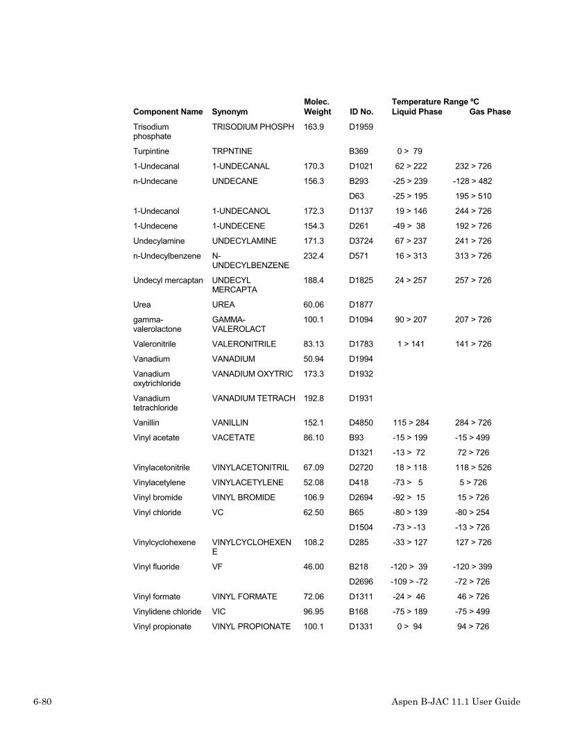
6-80 Aspen B-JAC 11.1 User Guide
Component Name SynonymMolec.Weight ID No.
Temperature Range ºCLiquid Phase Gas Phase
Trisodiumphosphate
TRISODIUM PHOSPH 163.9 D1959
Turpintine TRPNTINE B369 0 > 79
1-Undecanal 1-UNDECANAL 170.3 D1021 62 > 222 232 > 726
n-Undecane UNDECANE 156.3 B293 -25 > 239 -128 > 482
D63 -25 > 195 195 > 510
1-Undecanol 1-UNDECANOL 172.3 D1137 19 > 146 244 > 726
1-Undecene 1-UNDECENE 154.3 D261 -49 > 38 192 > 726
Undecylamine UNDECYLAMINE 171.3 D3724 67 > 237 241 > 726
n-Undecylbenzene N-UNDECYLBENZENE
232.4 D571 16 > 313 313 > 726
Undecyl mercaptan UNDECYLMERCAPTA
188.4 D1825 24 > 257 257 > 726
Urea UREA 60.06 D1877
gamma-valerolactone
GAMMA-VALEROLACT
100.1 D1094 90 > 207 207 > 726
Valeronitrile VALERONITRILE 83.13 D1783 1 > 141 141 > 726
Vanadium VANADIUM 50.94 D1994
Vanadiumoxytrichloride
VANADIUM OXYTRIC 173.3 D1932
Vanadiumtetrachloride
VANADIUM TETRACH 192.8 D1931
Vanillin VANILLIN 152.1 D4850 115 > 284 284 > 726
Vinyl acetate VACETATE 86.10 B93 -15 > 199 -15 > 499
D1321 -13 > 72 72 > 726
Vinylacetonitrile VINYLACETONITRIL 67.09 D2720 18 > 118 118 > 526
Vinylacetylene VINYLACETYLENE 52.08 D418 -73 > 5 5 > 726
Vinyl bromide VINYL BROMIDE 106.9 D2694 -92 > 15 15 > 726
Vinyl chloride VC 62.50 B65 -80 > 139 -80 > 254
D1504 -73 > -13 -13 > 726
Vinylcyclohexene VINYLCYCLOHEXENE
108.2 D285 -33 > 127 127 > 726
Vinyl fluoride VF 46.00 B218 -120 > 39 -120 > 399
D2696 -109 > -72 -72 > 726
Vinyl formate VINYL FORMATE 72.06 D1311 -24 > 46 46 > 726
Vinylidene chloride VIC 96.95 B168 -75 > 189 -75 > 499
Vinyl propionate VINYL PROPIONATE 100.1 D1331 0 > 94 94 > 726

Aspen B-JAC 11.1 User Guide 6-81
Component Name SynonymMolec.Weight ID No.
Temperature Range ºCLiquid Phase Gas Phase
Water WATER 18.01 B1 0 > 359 0 > 554
D1921 0 > 259 99 > 373
Xenon XENON 131.3 D959
m-Xylene XYLENEM 106.2 B138 0 > 259 0 > 499
D506 -47 > 86 139 > 726
o-Xylene XYLENEO 106.2 B73 -17 > 239 -17 > 257
D505 -25 > 141 144 > 726
p-Xylene XYLENEP 106.2 B146 0 > 279 0 > 499
D507 13 > 139 138 > 726
2,3-Xylenol 2,3-XYLENOL 122.2 D1170 88 > 216 216 > 726
2,4-Xylenol 2,4-XYLENOL 122.2 D1172 80 > 210 210 > 726
2,5-Xylenol 2,5-XYLENOL 122.2 D1174 80 > 211 211 > 726
2,6-Xylenol 2,6-XYLENOL 122.2 D1176 77 > 201 201 > 726
3,4-Xylenol 3,4-XYLENOL 122.2 D1177 91 > 226 226 > 726
3,5-Xylenol 3,5-XYLENOL 122.2 D1178 84 > 221 221 > 726
Component Name SynonymMolec.Weight ID No.
Temperature Range ºCLiquid Phase Gas Phase
Zinc ZINC 65.39 D2940 419 > 907
Zinc oxide ZINC OXIDE 81.39 D2975
Zinc sulfate ZINC SULFATE 161.5 D2981
❖ ❖ ❖ ❖

6-82 Aspen B-JAC 11.1 User Guide

Aspen B-JAC 11.1 User Guide 7-1
7 Priprops
IntroductionThe Priprops program allows you to create your own chemical properties databank for thosefluids not found in the B-JAC databank. By selecting the User databank when your privatecomponent is referenced in the B-JAC programs, the program will automatically access theprivate databank when the programs need to retrieve properties from the databank. Theprivate databank can accommodate up to 400 different fluids.
Accessing the Priprops databank
Accessing an existing component in the databankAccess the Priprops program by selecting Data Maintenance / Chemical Databank under theTools button located in the Menu Bar.
The user can view an existing B-JAC or Standard component in the databank by:
• selecting B-JAC or Standard from the databank option menu,
• then type in the component name, formula, B-JAC ID number, or synonym,
• if present the component will be shown with the stored properties.

7-2 Aspen B-JAC 11.1 User Guide
Adding a new component to PripropsAccess the Priprops program by selecting Data Maintenance / Chemical Databank under theTools button located in the Menu Bar.
To add a new private component to the databank:
• select the “User” databank
• type the reference name that you wish to call the component
• enter the required physical properties, constants, and curve fitting data for the component
• select the add button to add the new component to the database
• select the Update button to save the new component and to update the databank
Adding a new component using an existing component as atemplate:
• select the B-JAC or Standard databank
• search for similar component by typing in the name or reference to locate the component
• select the copy button to copy all the property information
• return to the User databank
• type in the name for the new component
• select the Add button to add the component
• select the Paste button to copy the properties from the standard databank
• modify as necessary the properties that differ from the standard component
• select the Update button to save the new component and to update the databank
Property ReferenceReference the Props section of this user guide for additional information on the componentsprovided in the B-JAC and standard databanks.

Aspen B-JAC 11.1 User Guide 7-3
Property Estimation
Property Curves Key Equation
0 .... Y = C1 + C2 * T + C3 * T**2 + C4 * T**3 + C5 * T**4 1 .... Y = exp (C1 + C2 / T + C3 * ln(T) + C4 * T ** C5) 2 .... Y = C1 * T ** C2 / (1 + C2 / T + C3 / T ** 2) 3 .... Y = C1 + C2 * exp (-C3 / T ** C4) 4 .... Y = C1 + C2 / T + C3 / T ** 3 + C4 / T ** 8 + C5 / T ** 9 5 .... Y = C1 / C2 ** (1 + (1 - T / C3) ** C4) 6 .... Y = C1 * (1 - T / Tc) **
(C2 + C3 * ( T / Tc) + C4 * (T / Tc) ** 2 + C5 * ( T / Tc) ** 3)
7 .... Y = C1 + C2 * ((C3 / T) / sinh (C3 / T)) ** 2 + C4 *
((C5 / T) / cosh (C5 / T)) ** 2
C1,C2,C3,... Coefficients
T ... Input Temperature in K or R Tc ... Critical Temperature in K or R Y ... Calculated Value ** ... Power Function
Property estimation based on NBPThe physical properties program can estimate physical properties for hydrocarboncomponents based on their normal boiling point (NBP) and either the molecular weight or thedegrees API. The estimated properties will be reasonably accurate for the hydrocarbons whichmeet the following criteria:
1. the normal boiling point is between 10 and 371 C (50 and 700 F)
2. the molecular weight is between 50 and 300
3. the degrees API is between 5 and 120

7-4 Aspen B-JAC 11.1 User Guide
To specify the component name, use one of the following formats:
NBCxxxMWyyy where xxx is NBP in C and yyy is the molecular weight
NBFxxxMWyyy where xxx is NBP in F and yyy is the molecular weight
NBCxxxAPIyyy where xxx is NBP in C and yyy is the degrees API
NBFxxxAPIyyy where xxx is NBP in F and yyy is the degrees API
Examples: NBC113MW156 NBC98.4API40 NBF323MW70 NBF215.8API44.2
Components outside the ranges specified above will NOT be accepted.
❖ ❖ ❖ ❖

Aspen B-JAC 11.1 User Guide 8-1
8 Qchex
IntroductionThe Qchex program calculates a budget price for shell and tube heat exchangers. It is thestand-alone version of the cost estimate routines which are built into the thermal designprogram Aspen Hetran.
These cost estimate routines are a subset of the cost estimate routines which are part of AspenTeams, the Aspen B-JAC program for mechanical design, detailed cost estimation, anddrawings of shell and tube heat exchangers. Whereas Aspen Teams does a completemechanical design and simulates the manufacture of every component, Qchex does only apartial mechanical design, estimating the thickness of some components. It then simulates thefabrication of some components while using more empirical correlations for othercomponents.
The Qchex program uses a database of material prices and fabrications standards. This is thesame database which the Teams program uses. The database can be changed by selecting theCost option under Tools.
The accuracy of the estimates derived from Qchex is dependent upon many factors, such as:the detail in which the heat exchanger is specified; the quantity of materials required; thedeviation from standard construction; the requirement for extreme design conditions; the useof premium materials (high alloys); the degree of competition; the country or region wherethe exchanger is purchased or installed. Refer to the "Qchex - Logic" section of this chapterfor a more detailed discussion of accuracy.

8-2 Aspen B-JAC 11.1 User Guide
If you have access to both Qchex and Teams, use the appropriate program based on thesecriteria:
Use Qchex Use Teams
When you need a budget price. When you need a precise price.
When you know relatively little about the exactconfiguration.
When you know the details of the exchangerconfiguration.
Wwhen a rough mechanical design is sufficient. When an exact mechanical design is required.
When you do not need material and labor details. When you need a bill of materials and the laborhour details.
Mechanical Scope
Design Code
ASME Section VIII Division 1
Front Head Types
A, B, C, N
Shell Types
E, F, G, H, J, K, X
Rear Head Types
L, M, N, P, S, T, U, W
Design Temperatures
As limited by ASME Code
Design Pressure
Approximately 3000 psi or 200 bar
Shell Diameter
No limitation

Aspen B-JAC 11.1 User Guide 8-3
Head Cover Types
Flat (bolted or welded), ellipsoidal, torispherical, conical, 90 degree elbow, hemispherical
Tube Diameter & Tube Length
No limitation
Tube Types
Plain or integral low fin
Materials
Those stored in the Metals databank
Systems of Measure
U.S., SI, or metric Units

8-4 Aspen B-JAC 11.1 User Guide
Input
Problem DefinitionBefore running Qchex, you must create an input file. The input is divided into these basicsections:• Problem Definition• Exchanger Geometry• Design Data.
Description
Headings
The headings are optional. You can specify from 1 to 5 lines of up to 75 characters per line.These entries will appear at the top of the input summary page. You can have this inputpreformatted, by specifying your preferences for headings in the Setup option under Tools.

Aspen B-JAC 11.1 User Guide 8-5
Exchanger GeometryThe Exchanger Geometry section is divided into two sections:• Exchanger Type• Exchanger Data.
Exchanger Type
Front head type
The front head type should be selected based upon the service needs for the exchanger. A fullaccess cover provided in the A, C, and N type heads may be needed if the tube side of theexchanger must be cleaned frequently. The B type is generally the most economical typehead.
Default: B Type

8-6 Aspen B-JAC 11.1 User Guide
Shell type
E type: Generally provides the best heat transfer but also the highest shell side pressure drop.Used for temperature cross applications where pure counter current flow is needed.
F type: This two pass shell can enhance shell side heat transfer and also maintain countercurrent flow if needed for temperature cross applications.
G type: Will enhance the shell side film coefficient for a given exchanger size.
H type: A good choice for low shell side operating pressure applications. Pressure drop canbe minimized. Used for shell side thermosiphons.
J type: Used often for shell side condensers. With two inlet vapor nozzles on top and thesingle condensate nozzle on bottom, vibration problems can be avoided.
K type: Used for kettle type shell side reboilers.
X type: Good for low shell side pressure applications. Units is provided with support plateswhich provides pure cross flow through the bundle. Multiple inlet and outlet nozzles or flowdistributors are recommended to assure full distribution of the flow along the bundle.
V type shell: This type is not currently part of the TEMA standards. It is used for very lowshell side pressure drops. It is especially well suited for vacuum condensers. The vapor belt isan enlarged shell over part of the bundle length.
Default: E type (except K type shell side pool boilers)

Aspen B-JAC 11.1 User Guide 8-7
Rear head type
The rear head type affects the thermal design, because it determines the outer tube limits andtherefore the number of tubes and the required number of tube passes.
Default: U type for kettle shells, M type for all others
Exchanger position
Specify that the exchanger is to be installed in the horizontal or vertical position.
Default: vertical for tube side thermosiphon; horizontal for all others

8-8 Aspen B-JAC 11.1 User Guide
Tubesheet type
The tubesheet type has a very significant effect on both the thermal design and the cost.Double tubesheets are used when it is extremely important to avoid any leakage between theshell and tube side fluids. Double tubesheets are most often used with fixed tubesheetexchangers, although they can also be used with U-tubes and outside packed floating heads.
Double tubesheets shorten the length of the tube which is in contact with the shell side fluidand therefore reduce the effective surface area. They also affect the location of the shell sidenozzles and the possible baffle spacings.
The gap type double tubesheet has a space, usually about 150 mm (6 in.), between the inner(shell side) and outer (tube side) tubesheets. The integral type double tubesheet is made bymachining out a honeycomb pattern inside a single thick piece of plate so that any leakingfluid can flow down through the inside of the tubesheet to a drain. This type is rare, since itrequires special fabrication tools and experience.
Default: normal single tubesheet(s)

Aspen B-JAC 11.1 User Guide 8-9
Tube to tubesheet joint
The tube to tubesheet joint does not affect the thermal design, but it does have a small effecton the mechanical design and sometimes a significant effect on the cost.
The most common type of tube to tubesheet joint is expanded only with 2 grooves. AlthoughTEMA Class C allows expanded joints without grooves, most fabricators will groove the tubeholes whenever the tubes are not welded to the tubesheet.
For more rigorous service, the tube to tubesheet joint should be welded. The most commonwelded joints are expanded and seal welded with 2 grooves and expanded and strengthwelded with 2 grooves.
Default: expanded only with 2 grooves for normal service; expanded and strength weldedwith 2 grooves for lethal service

8-10 Aspen B-JAC 11.1 User Guide
Expansion Joint
Select to include an expansion joint for fixed tubesheet exchangers.
This item only applies to fixed tubesheet heat exchangers; it is ignored for all other types. Thespecification of an expansion joint can have a significant effect on the cost.
The calculations required to determine the need for an expansion joint are quite complex andare beyond the scope of the Qchex program. These calculations are part of the Teamsprogram. However the Qchex program will estimate the differential expansion and make asimple determination on the need for an expansion joint.
Default: program based on estimated differential expansion
Exchanger Data
Gross Surface Area
If you do not know the exact configuration of the exchanger, you can specify the gross surfacearea, and the program will determine a reasonable geometry based on the program defaults. Ifyou do not specify the gross surface area, then you must provide values for the number oftubes, tube outside diameter, and tube length.
Shell outside diameter
If you do not specify the surface area, you must specify either the shell outside or insidediameter.
Provide the actual shell outside diameter. For pipe size exchangers, it is recommended toinput a shell OD rather than an ID since the program will reference standard pipe schedules.For exchangers made of rolled and welded plate materials, the shell OD or ID may beinputted. For kettles, the shell diameter is for the small cylinder near the front tubesheet, notthe large cylinder.
Shell inside diameter
Provide the actual shell inside diameter. If the shell OD has been specified, it is recommendto leave the ID blank. For pipe size exchangers, it is recommended to input a shell OD ratherthan an ID since the program will reference standard pipe schedules. For exchangers made ofrolled and welded plate materials, the shell OD or ID may be inputted. For kettles, the shelldiameter is for the small cylinder near the front tubesheet, not the large cylinder.

Aspen B-JAC 11.1 User Guide 8-11
Baffle spacing center to center
Specify the center to center spacing of the baffles in the bundle.
Baffle inlet spacing
Specify the inlet baffle spacing at the entrance to the bundle. For G, H, J, and X shell types,this is the spacing from the center of the nozzle to the next baffle. These types should have afull support under the nozzle. If left blank, the program will calculate the space based uponthe center to center spacing and the outlet spacing. If the outlet spacing is not provided, theprogram will determine the remaining tube length not used by the center to center spacing andprovide equal inlet and outlet spacings.
Number of baffles
The number of baffles is optional input. If you do not know the number of baffles, inlet, oroutlet spacing, you can approximate the number of baffles by dividing the tube length by thebaffle spacing and subtracting 1. However, if you do not know the number of baffles, it is bestto let the program calculate it, because it will also consider the tubesheet thickness and nozzlesizes. The number of baffles for G, H, and J type shells should include the baffle or fullsupport under the nozzle.
Tube length
Provide the tube length. The length should include the length of tubes in the tubesheets. ForU-tube exchangers, provide the straight length to the U-bend tangent point.
Number of tubes
Specify the number of tube holes in the tubesheet. This is the number of straight tubes or thenumber of straight lengths for a U-tube. If you specify the number, the program will check tomake sure that number of tubes can fit into the shell. If you do not specify it, the program willcalculate number of tubes using the tubesheet layout subroutine.
Tube passes
Provide the number of tube passes in the exchanger.

8-12 Aspen B-JAC 11.1 User Guide
Kettle outside diameter
Provide the actual kettle outside diameter. For pipe size exchangers, it is recommended toinput a kettle OD rather than an ID since the program will reference standard pipe schedules.For exchangers made of rolled and welded plate materials, the kettle OD or ID may beinputted.
Tube type
The program covers plain tubes and external integral circumferentially finned tubes.
Externally finned tubes become advantageous when the shell side film coefficient is muchless than the tube side film coefficient. However there are some applications where finnedtubes are not recommended. They are not usually recommended for cases where there is highfouling on the shell side, or very viscous flow, or for condensation where there is a high liquidsurface tension.
The dimensional standards for Wolverine's High Performance finned tubes, are built into theprogram. These standard finned tubes are available in tube diameters of 12.7, 15.9, 19.1, and25.4 mm or 0.5, 0.625, 0.75, and 1.0 inch.
Default: plain tubes
Fin density
If you specify fin tubes as the tube type, then you must specify the desired fin density (i.e. thenumber of fins per inch or per meter depending on the system of measure). Since the possiblefin densities are very dependent on the tube material, you should be sure that the desired findensity is commercially available.
The dimensional standards for finned tubes made by Wolverine, and High Performance Tubeare built into the program. If you choose one of these, the program will automatically supplythe corresponding fin height, fin thickness, and ratio of tube outside to inside surface area. Ifyou do not choose one of the standard fin densities, then you must also supply the other findata, which follows in the input.

Aspen B-JAC 11.1 User Guide 8-13
The standard fin densities for various materials are:Carbon Steel 19
Stainless Steel 16, 28
Copper 19, 26
Copper-Nickel 90/10 16, 19, 26
Copper-Nickel 70/30 19, 26
Nickel Carbon Alloy 201 19
Nickel Alloy 400 (Monel) 28
Nickel Alloy 600 (Inconel) 28
Nickel Alloy 800 28
Hastelloy 0
Titanium 30
Admiralty 19, 26
Aluminum-Brass Alloy687
9
Tube outside diameter
You can specify any size for the tube outside diameter, however the correlations have beendeveloped based on tube sizes from 10 to 50 mm (0.375 to 2.0 inch). The most common sizesin the U.S. are 0.625, 0.75, and 1.0 inch. In many other countries, the most common sizes are16, 20, and 25 mm.
If you do not know what tube diameter to use, start with a 20 mm diameter, if you work withISO standards, or a 0.75 inch diameter if you work with American standards. This size isreadily available in nearly all tube materials. The primary exception is for graphite which ismade in 32, 37, and 50 mm or 1.25, 1.5, and 2 inch outside diameters.
For integral low fin tubes, the tube outside diameter is the outside diameter of the fin.
Default: 19.05 mm or 0.75 inch
Tube wall thickness
You should choose the tube wall thickness based on considerations of corrosion, pressure,and company standards. If you work with ANSI standards, the thicknesses follow the BWGstandards. These are listed for your reference in the Appendix of this manual and in the Helpfacility.
The program defaults are a function of material per TEMA recommendations and a functionof pressure. The Hetran program will check the specified tube wall thickness for internalpressure and issue a warning if it is inadequate.

8-14 Aspen B-JAC 11.1 User Guide
The selections to the right of the input field are provided for easy selection using the mouse.The values are not limited to those listed.
Default: 0.065 in. or 1.6 mm for carbon steel;
0.028 in. or 0.7 mm for titanium;
0.180 in. or 5 mm for graphite;
0.049 in. or 1.2 mm for other materials
Tube pitch
The tube pitch is the center to center distance between two adjacent tubes. Generally the tubepitch should be approximately 1.25 times the tube O.D. It some cases, it may be desirable toincrease the tube pitch in order to better satisfy the shell side allowable pressure drop. It is notrecommended to increase the tube pitch beyond 1.5 times the tube O.D.. Minimum tubepitches are suggested by TEMA as a function of tube O.D., tube pattern, and TEMA class.The program will default to the TEMA minimum tube pitch, if you are designing to TEMAstandards. The DIN standards also cover tube pitch. The DIN tube pitches are a function oftube O.D., tube pattern, and tube to tubesheet joint. The program will default to the DINstandard if you are designing to DIN standards.
Default: TEMA minimum or DIN standard
Tube Pattern
The tube pattern is the layout of the tubes in relation to the direction of the shell sidecrossflow, which is normal to the baffle cut edge. The one exception to this is pool boiling ina kettle type reboiler where the tube supports are sometimes baffles with a vertical cut. Usetriangular when you want to maximize the shell side film coefficient and maximize thenumber of tubes, and shell side cleaning is not a major concern. If you must be able tomechanically clean the shell side of the bundle, then choose square or rotated square. Rotatedsquare will give the higher film coefficient and higher pressure drop, but it will usually havefewer tubes than a square layout. Rotated triangular is rarely the optimum, because it has acomparatively poor conversion of pressure drop to heat transfer. Square is recommended forpool boilers to provide escape lanes for the vapor generated.
Default: triangular - fixed tubesheet exchangers, square - pool boilers

Aspen B-JAC 11.1 User Guide 8-15
Baffle Type
SingleSegmental
DoubleSegmental
TripleSegmental Full Support
No Tubesin Window
Rod Strip
Baffle types can be divided up into two general categories: segmental baffles and grid baffles.Segmental baffles are pieces of plate with holes for the tubes and a segment that has been cutaway for a baffle window. Single, double, triple, and no tubes in window are examples ofsegmental baffles. Grid baffles are made from rods or strips of metal, which are assembled toprovide a grid of openings through which the tubes can pass. The program covers two types ofgrid baffles: rod baffles and strip baffles. Both are used in cases where the allowable pressuredrop is low and the tube support is important to avoid tube vibration.
Segmental baffles are the most common type of baffle, with the single segmental bafflebeing the type used in a majority of shell and tube heat exchangers. The single segmentalbaffle gives the highest shell film coefficient but also the highest pressure drop. A doublesegmental baffle at the same baffle spacing will reduce the pressure drop dramatically(usually somewhere between 50% - 75%) but at the cost of a lower film coefficient. Thebaffles should have at least one row of overlap and therefore become practical for a 20 mm or0.75 in. tube in shell diameters of 305 mm (12 in.) or greater for double segmental and 610(24 in.) or greater for triple segmental baffles. (Note: the B-JAC triple segmental baffle isdifferent than the TEMA triple segmental baffle.)
Full Supports are used in K and X type shells where baffling is not necessary to direct theshell side flow.
No Tubes In Window is a layout using a single segmental baffle with tubes removed in thebaffle windows. This type is used to avoid tube vibration and may be further enhanced withintermediate supports to shorten the unsupported tube span. The standard abbreviation for notubes in the window is NTIW.
Rod Baffle design is based on the construction and correlations developed by PhillipsPetroleum. Rod baffles are limited to a square tube pattern. The rods are usually about 6 mm(0.25 in.) in diameter. The rods are placed between every other tube row and welded to acircular ring. There are four repeating sets where each baffle is rotated 90 degrees from theprevious baffle.

8-16 Aspen B-JAC 11.1 User Guide
Strip Baffles are normally used with a triangular tube pattern. The strips are usually about 25mm (1 in.) wide and 3 mm (0.125 in.) thick. The strips are placed between every tube row.Intersecting strips can be notched to fit together or stacked and tack welded. The strips arewelded to a circular ring. Strip baffles are also sometimes referred to as nest baffles.
Default: single segmental except X shells; full support for X shell
Baffle cut (% of diameter)
The baffle cut applies to segmental baffles and specifies the size of the baffle window as apercent of the shell I.D. For single segmental baffles, the program allows a cut of 15% to45%. Greater than 45% is not practical because it does not provide for enough overlap of thebaffles. Less than 15% is not practical, because it results in a high pressure drop through thebaffle window with relatively little gain in heat transfer (poor pressure drop to heat transferconversion). Generally, where baffling the flow is necessary, the best baffle cut is around25%.
For double and triple segmental baffles, the baffle cut pertains to the most central bafflewindow. The program will automatically size the other windows for an equivalent flow area.
Refer to the Appendix for a detailed explanation of baffle cuts.
Default: single segmental: 45% for simple condensation and pool boiling; 25% for all others;double segmental: 28% (28/23); triple segmental: 14% (14/15/14)
Baffle cut orientation
Horizontal Vertical Rotated
The baffle orientation applies to the direction of the baffle cut in segmental baffles. It is verydependent on the shell side application for vertical heat exchangers; the orientation has littlemeaning or effect. It may affect the number of tubes in a multipass vertical heat exchanger.For horizontal heat exchangers it is far more important.
For a single phase fluid in a horizontal shell, the preferable baffle orientation of singlesegmental baffles is horizontal, although vertical and rotated are usually also acceptable. Thechoice will not affect the performance, but it will affect the number of tubes in a multipassheat exchanger. The horizontal cut has the advantage of limiting stratification ofmulticomponent mixtures, which might separate at low velocities.

Aspen B-JAC 11.1 User Guide 8-17
The rotated cut is rarely used. Its only advantage is for a removable bundle with multiple tubepasses and rotated square layout. In this case the number of tubes can be increased by using arotated cut, since the pass partition lane can be smaller and still maintain the cleaning pathsall the way across the bundle. (From the tubesheet, the layout appears square instead ofrotated square.)
For horizontal shell side condensers, the orientation should always be vertical, so that thecondensate can freely flow at the bottom of the heat exchanger. These baffles are frequentlynotched at the bottom to improve drainage. For shell side pool boiling, the cut (if using asegmental baffle) should be vertical. For shell side forced circulation vaporization, the cutshould be horizontal in order to minimize the separation of liquid and vapor.
For double and triple segmental baffles, the preferred baffle orientation is vertical. Thisprovides better support for the tube bundle than a horizontal cut which would leave thetopmost baffle unsupported by the shell. However this can be overcome by leaving a smallstrip connecting the topmost segment with the bottommost segment around the baffle windowbetween the O.T.L. and the baffle o.d.
Default: vertical for double and triple segmental baffles;
vertical for shell side condensers;
vertical for F, G, H, and K type shells;
horizontal for all other cases
Nozzles
You should specify the nozzle diameters if known. Use nominal pipe sizes. If you do notspecify a value, the program assumes nozzles with a diameter equal to one-third the shelldiameter. The program determines the number of nozzles required based on the specified shelltype and automatically determines the nozzle flange rating.

8-18 Aspen B-JAC 11.1 User Guide
Design Data
Materials- Vessel
Specify materials for the main components: Shell, Head, Tubes, material, Baffle, Tubesheet,Tubesheet cladding, Double tubesheet (inner). The Qchex program uses the Metals databankto retrieve material properties and prices. You can use the generic material types such as"carbon steel" which the program will assign actual default material specifications dependingon the product form. For carbon steel plate, a material specification of SA-516-70 will beused for an ASME design. Appropriate specifications will be selected for other designconstruction codes. To select a specific material specification, use the Databank Searchbutton to view the databank listing. If you want to exclude the pricing of a particularcomponent, for example the tubes, specify a zero for that material. The default materials canbe changed using the utility DefMats. Reference the Appendix for a complete list of genericmaterials.
Default: carbon steel.
Gasket Materials
Specify materials for the main components: Gasket for shell side, Gasket for tube side.
The Qchex program uses the Metals databank to retrieve material properties and prices. Youmay specify a generic material number or a code for a specific material specification. Toselect a specific material specification, use the Databank Search button to view the databanklisting. If you want to exclude the pricing of a particular component, for example the tubes,specify a zero for that material.
TEMA class
If you want the heat exchanger to be built in accordance with the TEMA standards, choosethe appropriate TEMA class - B, C, or R. If TEMA is not a design requirement, then specifyCody only, and only the design code will be used in determining the mechanical design.
Default: TEMA B
Design pressure
This is the pressure, which is used in the mechanical design calculations. It influences theshell, head, and tubesheet required thicknesses and therefore affects the thermal design. Thisis in gauge pressure so it is one atmosphere less than the equivalent absolute pressure.

Aspen B-JAC 11.1 User Guide 8-19
Design temperature
This is the temperature, which is used in the mechanical design calculations. It influences theshell, head, and tubesheet required thicknesses and therefore affects the thermal design.
Mean Metal Temperatures
These temperatures are used if the program needs to determine if an expansion joint should beincluded in the cost.
Qchex - Program Operation
Running QCHEX
To start the Qchex calculation select the Run button on the Tools Bar.
If the program has any special messages to display, these will appear at this point.
Displaying Results
To display the results of the calculations, select an item on the navigator.
Changing Units of Measure
By selecting from the units of measure in the Tools Bar, you change the units of measuredisplayed.
Choosing Output for Printing
You can request the printed output by selecting the File command on the Menu Bar and thenthe Print command.
Exiting from the Program
Once you have completed the Qchex estimate, you may exit Qchex by selecting the Filecommand from the Menu Bar and then selecting Close to close the file.

8-20 Aspen B-JAC 11.1 User Guide
Qchex - ResultsThe results section consists of three sections:• Input Summary• Warnings & Messages• Design Summary• Cost Summary.
Input SummaryA summary of the inputted parameters for the budget estimate are shown.
Warnings & MessagesAspen Hetran provides an extensive system of warnings and messages to help the designer ofheat exchanger design. Messages are divided into five types. There are several hundredmessages built into the Aspen Hetran program. Those messages requiring further explanationare described here.
Warning Messages:
These are conditions, which may be problems, however the program will continue.
Error Messages:
Conditions which do not allow the program to continue.
Limit Messages:
Conditions which go beyond the scope of the program.
Notes:
Special conditions which you should be aware of.
Suggestions:
Recommendations on how to improve the design.

Aspen B-JAC 11.1 User Guide 8-21
Design SummaryThe design summary provides the pertinent mechanical parameters shown on the constructionportion of the TEMA specification sheet.
Cost SummaryThe budget pricing for the exchanger is shown. The cost of material, cost of labor, mark upare provided.
Qchex LogicMechanical Design
The Qchex program performs an approximate mechanical design of the heat exchangercomponents so that the material weight can be determined. Some of the more significantassumptions used in the analysis are summarized below.
Design Pressure
Due to limitations of the analytic procedure at high design pressures, thicknesses of flanges,tubesheets and flat covers are limited to 12 in. or 300 mm.
The maximum allowable design pressure for a TEMA W-type externally sealed floatingtubesheet is as detailed in TEMA.
Design Temperature and Allowable Stresses
Design temperatures are limited by the ASME maximum allowable temperature for thematerial specified. For design temperatures exceeding this maximum, the allowable stress isdetermined at the maximum allowable temperature and a warning is displayed.
Design temperature for a TEMA W-type unit is limited as detailed in TEMA.
Corrosion Allowance
Corrosion allowance for cylinders, covers, and tubesheets is determined in accordance withTEMA.

8-22 Aspen B-JAC 11.1 User Guide
Cylinders and Covers
Calculations are to the ASME Code Section VIII Division 1.
Thickness calculations are based on internal pressure loadings and assume spot radiography.
Flat bolted covers which are not made of carbon steel or low alloy steel are assumed to belined with an alloy liner.
Cylinders and Covers
Minimum TEMA thicknesses are checked.
Component weights are calculated from finished dimensions, and rough dimensions are usedto determine material costs.
Tubesheets
Approximate tubesheet thicknesses are calculated in accordance with TEMA.
Tubesheets exceeding 6 in. or 152 mm in thickness and not made of carbon or low alloy steelare assumed to be clad. The number of clad surfaces is dependent upon the shell and tube sidematerials.
Minimum TEMA thicknesses are checked.
The tubesheet thickness is limited to a maximum of 12 in. or 300 mm.
Rough weights are calculated assuming the tubesheet is fabricated from a square plate.
If a double tubesheet is specified, the shell side tubesheet thickness is based on the shell sidedesign pressure.
Flanges
Approximate flange thicknesses are determined using a modified bending formula.
Ring flanges are assumed for carbon and low alloy construction and for high alloy flangesless than or equal to 1 in. or 25 mm in thickness. All other flanges are assumed to be lap jointwith a carbon steel ring.
The flange thickness is limited to a maximum of 12 in. or 300 mm.
Rough weights are calculated assuming the flanges are fabricated from forged rings.

Aspen B-JAC 11.1 User Guide 8-23
Tubes
Qchex accesses the same routines which are used in TEAMS to determine tube prices for bareor finned tubes.
Nozzles and Nozzle Flanges
Inlet, outlet, and condensate nozzle sizes can be specified. The program automaticallydetermines the number of each type of nozzle based on the shell and head types specified.
Finished and rough weights are based on correlations which consider design pressure andnozzle diameter.
Material Prices
The Qchex program accesses the same material price database which is used by the costroutines in the Teams program. This database contains several hundred prices and ismaintained and updated by B-JAC as the market conditions change. Users can maintain theirown material price database by using the COST database.
The material designators listed in this section are converted to the appropriate 4 digit materialdesignators used by the Teams and Metals programs. You can change the correspondencebetween the 1 or 2 digit numbers and the 4 digit numbers by using the Defmats database.
Material unit costs are multiplied by the rough weight to determine the component materialcost. The material price for the heat exchanger is determined by adding all of the componentmaterial costs.
If you do not want the price of a particular part of the exchanger to be included in the totalprice, you should assign a value of zero for that part material. For instance, the programwould not include the cost of the tubing in the selling price if you set the tube material tozero.

8-24 Aspen B-JAC 11.1 User Guide
Labor Hours
The labor hours required to fabricate the shell and heads of the heat exchanger are calculatedfrom correlations that were developed by Aspen B-JAC based on several hundred laborestimates for a wide variety of exchanger types and design conditions. These correlations area function of design pressure, shell diameter, weight, tube length, and material.
The labor hours for the bundle are determined more precisely using the same techniques usedin the cost estimate portion of the Teams program. This portion of the program accesses thedatabase of fabrication standards (machining and drilling speeds). This database is maintainedby Aspen B-JAC or you can modify this database for your own use by running the Costdatabase.
Drilling and machining speeds for the tubesheets and baffles are based on the tubesheetmaterial. Labor hours for loading tubes, tube-to-tubesheet joint procedures, and bending U-tubes are the same as those calculated by the Teams cost routines.
Budget Price
The budget price for the exchanger is calculated by adding the material costs, labor costs, andmarkups on material and labor. Labor costs are based on the total shop fabrication hours andthe burdened labor rate. This rate and the markups on material and labor are the same as usedin the Teams program.
The price is for one heat exchanger and does not include any shipping or escalation costs.
The Qchex program is intended to be used as a budget estimating tool. The accuracy of theestimate is dependent upon many factors, including:• Accuracy of the Heat Exchanger Configuration
An estimate where the tube length, tube side, and shell size are known will be much moreaccurate than an estimate based on surface area alone.
Quantity of Materials
The material prices stored in the Aspen B-JAC standard material price file are based onaverage quantity brackets. Very small or very large quantities will affect the accuracy of thematerial prices.

Aspen B-JAC 11.1 User Guide 8-25
Non-standard Construction
As the construction becomes more non-standard the accuracy of the estimate decreases.
Extreme Design Conditions
When the design pressure on one or both sides becomes very high the exact mechanicaldesign becomes more important. In these cases the TEAMS program should be used.
Premium Materials
When using premium materials (for example titanium) the material price can be very volatileand highly dependent upon quantity.
Non-competitive or Rush Orders
The budget estimate is less accurate for non-competitive situations or when delivery time is apremium.
Regional Differences
The actual price is dependent upon the country of manufacture and in the case of the UnitedStates and Canada, it is dependent upon the region of manufacture. The Qchex program doesnot reflect these regional differences.

8-26 Aspen B-JAC 11.1 User Guide
Qchex ReferencesThere are relatively few published sources of information on heat exchanger cost estimating.Most of the logic and much of the data in the Qchex program have come from the fabricationexperience of the engineers at B-JAC who have worked with heat exchanger manufacturers.
For a further understanding of some of the underlying concepts in cost estimating, you canrefer to the following publications:
Heat Exchanger Cost Estimating
Computerized Cost Estimation of Heat Exchangers, Bruce Noe‚ and Gregory Strickler, 21stNational Heat Transfer Conference, ASME, 83-HT-62, 1983.
Manufacturing Cost Estimating
Manufacturing Cost Estimating, Phillip Ostwald, Society of Manufacturing Engineers,Dearborn, Michigan, 1980.
Basic Programming Solutions for Manufacturing, J. E. Nicks, pp. 35-80, Society ofManufacturing Engineers, Dearborn, Michigan, 1982.
Manufacturing Operations and Speeds
Tool & Manufacturing Engineers Handbook, Daniel Dallas, Society of ManufacturingEngineers, Dearborn, Michigan, 1976.
The Procedure Handbook of Arc Welding, The Lincoln Electric Company, Cleveland, Ohio,1973.
Machining Data Handbook, Metcut Research Associates Inc., Cincinnati, Ohio, 1972.
❖ ❖ ❖ ❖

Aspen B-JAC 11.1 User Guide 9-1
9 Ensea
IntroductionEnsea is a program that lays out the tube holes in the tubesheet of a shell and tube heatexchanger. It covers practically all sizes and layout types encountered in industrial heatexchangers. In addition to locating every tube hole, it will also locate the baffle cuts and anappropriate number of tie rods.
The program has three modes of optimization. These are:• Maximize the number of tubes for a specified shell diameter• Optimize the layout for a specified shell diameter and number of tubes• Minimize the shell diameter for a specified number of tubes
The layout can be symmetrical or asymmetrical top to bottom; it is always symmetrical rightto left. For multipass layouts, the program has a sophisticated optimization routine whichmoves the pass partitions to maximize the number of tubes while reasonably balancing thenumber of tubes per pass.
Ensea has additional capabilities for U-tube layouts. It will determine a U-bend scheduleshowing the number and length of each different U-tube and calculate the total length of all ofthe tubes.
The appropriate sections of the TEMA standards are built into the program to provide defaultvalues for the clearances. The defaults can be overridden if desired.
As part of the output from Ensea, you can create a drawing of the tubesheet layout which canbe exported to various graphics devices and CAD systems.
The Ensea program also provides a means of making changes to the number of tube rows andthe number of tubes per row, or if you have an existing tubesheet layout, you can reproducethe layout and make a drawing by specifying the tube row data.

9-2 Aspen B-JAC 11.1 User Guide
The Ensea program contains the same tubesheet layout routines used in the thermal designprogram, Aspen Hetran, and the mechanical design program, Teams. Therefore the tubesheetlayout determined by Ensea matches the tube counts used in the Aspen Hetran program whenused in design mode.
Mechanical Scope
Tube Diameter
no limitation
Tube Pitch
No limitation
Tube Patterns
Triangular, rotated triangular, square, rotated square
Tube Passes
1 to 16
Tube Rows
Maximum of 200
Shell size
No limitation if shell i.d. is specified a maximum limit of 120 in. or 3048 mm when programsearches for shell i.d.
Impingement Plate
None, plate on bundle, plate in nozzle dome
Pass Layouts
Quadrant, mixed, ribbon

Aspen B-JAC 11.1 User Guide 9-3
Baffle Types
Segmental - single, double, triple
Grid - strip, rod
No tubes in window
Full supports
Baffle Cuts
Horizontal, vertical, rotated
Single segmental
Double segmental
Triple segmental
Tie Rods
4 to 12, in increments of 2
Units of Measure
US, SI, Metric

9-4 Aspen B-JAC 11.1 User Guide
InputBefore running Ensea, you must create an input file. The input is divided into these sections:• Problem Definition• Exchanger Geometry• Tube Row Details
Problem Definition
Headings
The headings, 1-5 lines which will appear at the top of the input summary and in the titleblock of the drawings. Note that only the first 40 characters of each line will appear on thedrawings.
The headings are optional. You can specify from 1 to 5 lines of up to 75 characters per line.These entries will appear at the top of each page of printed output and at the top of the heatexchanger specification sheet. You can have this input preformatted, by specifying yourpreferences for headings in the Setup option under Tools.
Application Options
Application Type
When you request "design a tube layout for specified vessel diameter", the program willhold the specified vessel diameter and determine the number of tube holes that will fit basedupon other tube layout information provided.
The second option to " design a tube layout for specified number of tubes" allows youspecify the number of tubes and the program will determine what shell size is required forthat number of tubes based upon tube and baffle information you have provided.
The last option " specify the tube layout" allows you to specify the number of tube holes ineach row, the location of each row, the tie rods, baffle cuts, and pass partitions. This option isprimarily aimed at preparing a drawing of an existing or known tubesheet layout.

Aspen B-JAC 11.1 User Guide 9-5
Tube Layout option
Once you have run the Ensea program and have generated a tube layout, you can interactivelymake modifications to the tube layout.
Tubes: Tubes can be removed from the layout by clicking on the tube to be removed (tubewill be highlighted in red) and then selecting the red X in the menu. If you want to designatea tube as a plugged tube or as a dummy tube, click on the tube (tube will be highlighted inred) and then select the plugged tube icon or dummy tube icon from the menu.
Tie Rods: To remove a tie rod, click on the tie rod (tie rod will be highlighted in red) andthen select the red X in the menu. To add a tie rod, select the add a tie rod icon in the menuand then specify the location for the tie rod.
Sealing Strips: To remove a sealing strip, click on the sealing strip (sealing strip will behighlighted in red) and then select the red X in the menu. To add a sealing strip, select theadd a sealing strip icon in the menu and then specify the location for the sealing strip. Onceyou have completed your changes to the tube layout, you may want to elect to fix the layoutfor subsequent Ensea runs by selecting the "Use existing layout" option located on theTubsheet Layout tab.
TEMA Class
If you want the heat exchanger to be built in accordance with the TEMA standards, choosethe appropriate TEMA class - B, C, or R. The TEMA class will affect the clearance lane forpass partitions and the standard minimum tube pitch.
If TEMA is not a design requirement, then specify code only. Even if you specify "codeonly," the program will default to TEMA clearances and diameters, if not specified. Theprimary difference is that for a removable bundle with a square or rotated square pattern, theprogram will not force cleaning lanes all the way across the bundle if you specify "codeonly."
Default: TEMA B
Tube Layout Option
You can select to have the Ensea program generate a new tube layout every time the programruns or you can select to use an existing layout. For the second option, you must first runEnsea to establish a layout and then select the option to use the existing layout for allsubsequent runs.
Default: create a new layout

9-6 Aspen B-JAC 11.1 User Guide
Drawing
Once you have a specified an exchanger geometry, executed Ensea, and then selected to usean existing layout in the Applications Options, you can interactively make modifications tothe tube layout.
Tubes: Tubes can be removed from the layout by clicking on the tube to be removed (tubewill be highlighted in red) and then selecting the red X in the menu. If you want to designatea tube as a plugged tube or as a dummy tube, click on the tube (tube will be highlighted inred) and then select the plugged tube icon or dummy tube icon from the menu.
Tie Rods: To remove a tie rod, click on the tie rod (tie rod will be highlighted in red) andthen select the red X in the menu. To add a tie rod, select the add a tie rod icon in the menuand then specify the location for the tie rod.
Sealing Strips: To remove a sealing strip, click on the sealing strip (sealing strip will behighlighted in red) and then select the red X in the menu. To add a sealing strip, select theadd a sealing strip icon in the menu and then specify the location for the sealing strip.

Aspen B-JAC 11.1 User Guide 9-7
Exchanger Geometry
Exchanger
Front head type
The front head type does not affect the tubesheet layout. It is included in the input forcompleteness of the TEMA designation (e.g., BEM).
Default: B type front head

9-8 Aspen B-JAC 11.1 User Guide
Shell type
The shell type does not affect the tubesheet layout, except for those cases where there is alongitudinal baffle (shell types: F, G, and H). For these cases the program avoids a solutionwhere the longitudinal baffle would pass through the middle of a pass, for example a 6 passquadrant layout.
Default: E type shell
Rear head type

Aspen B-JAC 11.1 User Guide 9-9
The rear head type significantly affects the tubesheet layout, because it determines the outertube limits and therefore the number of tubes.
The L, M, and U type rear heads will all have the same OTL, which the Ensea program willaccurately calculate. The P, S, T, and W (and to some extent the N) rear head types each havean OTL which is very dependent upon the mechanical design. The Ensea program willestimate the clearance requirements for these other heads, but the OTL may not be exact. Usethe Teams program to determine the exact outer tube limit for floating head heat exchangers.
Default: M type rear head (U-tube for K type shells)
Front head inside diameter
You should specify the front head inside diameter whenever it is less than the shell insidediameter. If you leave it zero, the program will use the shell ID to determine the OTL.
Shell inside diameter
You should always specify the shell ID except when you want to have the program determinethe smallest shell size which will contain the given number of tubes (see "Number of Tubes"below).
Ensea uses the shell ID. to calculate the outer tube limit (if not specified in input), calculatethe baffle OD, locate the tie rods, locate the baffle cut, and as a reference for limiting thelayout along the horizontal and vertical axis.
Shell outside diameter
The program will determine the smallest shell O.D. based on specified I.D. For shell I.D.within 24-inches, the program defaults tube wall thickness as 0.375-inch. Otherwise, theprogram determines shell O.D. based on 0.5-inch tube wall thickness.
Hetran -- Provide the actual shell outside diameter. For pipe size exchangers, it isrecommended to input a shell OD rather than an ID since the program will reference standardpipe schedules. For exchangers made of rolled and welded plate materials, the shell OD or IDmay be inputted. For kettles, the shell diameter is for the small cylinder near the fronttubesheet, not the large cylinder.
Teams --- If you specify an outside diameter, the program will hold the outside diameter andcalculate and inside diameter based upon the calculated required cylinder thickness. If a pipematerial is specified, shells 24 inches and smaller, it is recommended to input the outsidediameter so that a standard pipe wall thickness can be determined.

9-10 Aspen B-JAC 11.1 User Guide
Outer tube limit diameter
The outer tube limit (o.t.l.) is the diameter of the circle beyond which no portion of a tube willbe placed. The program will allow the outer edge of a tube to be on the OTL.
You can ask the program to calculate the OTL by specifying a zero, in which case theprogram will choose an OTL. based on the front and rear head types and the front head IDand the shell i.d. The OTL, which the program calculates, should be exact for fixed tubesheetexchangers with rear head types L and M and U-tube exchangers (rear head type U). It maynot be exact for exchangers with N type heads, floating head exchangers (rear head types P, S,or T), or floating tubesheet exchangers (rear head type W), since the program makesassumptions on the gasket width, bolt size, and barrel thickness. For an exact OTL, youshould use the mechanical design program Teams.
Tubes & Baffles
Number of tube holes
If you want the program to maximize the number of tubes for a given shell size, you shouldleave this input field blank.
When you have already established an exact number of tubes, you should specify the numberof tubes for this entry. The program will then attempt to find a reasonable layout with thattube count. If it cannot find a layout with that many tubes, it will show the layout with themaximum tubes it could find. If the specified tube count is below the program's normalsolution, Ensea will remove tubes until it reaches the desired count.
If you want to find the smallest shell i.d. to contain a given number of tubes, enter the desiredtube count, and enter zeros for the shell i.d. and outer tube limits. This will cause the programto search through several shell sizes until it finds the smallest size, rounded to the nearest 0.25inch or the nearest 5 mm, depending upon the system of measure. For U-tubes, you shouldspecify the number of tube holes (two times the number of U's).
Default: program calculated
Tube outside diameter
You can specify any size for the tube outside diameter.
Tube pitch
The tube pitch is the distance from tube center to tube center within the tube pattern.
Default: per TEMA standards for specified tube diameter

Aspen B-JAC 11.1 User Guide 9-11
Tube pattern
The tube pattern is the layout of the tubes in relation to the direction of the shell sidecrossflow, which is normal to the baffle cut edge. The one exception to this is pool boiling ina kettle type reboiler where the tube supports are sometimes baffles with a vertical cut.
Type of Baffles
SingleSegmental
DoubleSegmental
TripleSegmental Full Support
No Tubesin Window
Rod Strip
If you specify no tubes in the window (NTIW), the program will not place any tube beyondthe baffle cut, minus an edge distance of 0.125 in or 3.2 mm.
The program also covers full supports and the two types of grid baffles: rod baffles and stripbaffles. Rod baffles are limited to a tube pattern of square or rotated square. Strip baffles arefor triangular tube patterns.
Default: single segmental ( full support X type shell)

9-12 Aspen B-JAC 11.1 User Guide
Baffle Cut
For single segmental baffles, specify the percentage of the baffle window height compared tothe shell i.d. For double and triple segmental baffles, specify the percentage of the innermostbaffle window height compared to the shell i.d.
The selections to the right of the input field are provided for easy selection using the mouse.The values are not limited to those listed.
For single segmental baffles the cut should be between 15 and 45%. For double segmentalbaffles the cut should be between 30 and 40%. For triple segmental baffles the cut should bebetween 15 and 20%. For full supports and grid baffles the baffle cut should be zero.
Refer to the Appendix for more information on segmental baffle cuts.
Baffle Cut Orientation
The baffle cut can be horizontal, vertical, or rotated 45 degrees. The orientation will affect theappearance of the tube pattern and the location of the tie rods. The rotated cut may be usedonly with a square or rotated square tube pattern.
Default: horizontal cut
Number and Diameter of Tie Rods
The program will optimize the location of the tie rods to maximize the number of tube holesin the layout. The number of tie rods should be specified by assigning an even numberbetween 4 and 12.
Default: per TEMA Standards

Aspen B-JAC 11.1 User Guide 9-13
Tie Rod and Spacer outside diameter
You can specify the tie rod and spacer outside diameters or allow the program to use defaultsizes.
Defaults:Tie Rod Spacer Tie Rod Spacer
mm mm in in
6.5 12.7 0.25 0.5
9.5 15.9 0.375 0.625
12.7 19.1 0.5 0.75
15.9 25.4 0.625 1.0
Tube Layout
Pass layout type
For 1, 2, or 3 pass layouts, the value of this entry is not pertinent. For pass layouts of 4 ormore tube passes, it will determine how the tube side inlet and outlet nozzles will enter theheads and the locations of the pass partitions.
The difference between ribbon type and mixed type layouts is in how the inner passes (thepasses between the first and last passes) are constructed. In the ribbon layout, each passstretches from one side of the shell to the other, whereas the mixed layout has a vertical passpartition plate dividing the inner passes. A 4 pass layout is shown below in each of the layouttypes.
Quadrant Mixed Ribbon
Mixed and ribbon type layouts have the advantage of easier nozzle installation, especiallywith relatively large nozzles. Ribbon type is also preferable when there is a large pass to passtemperature change, since ribbon type minimizes the local temperature stresses in thetubesheet. Quadrant type layouts have the advantage of normally (but not always) yielding agreater number of tubes.
U-tube layouts of 4 or more passes are restricted to the quadrant type.
Default: program will optimize to the greatest number of tubes.

9-14 Aspen B-JAC 11.1 User Guide
Number of tube passes
You can specify any number of passes from 1 to 16.
Maximum % deviation in tubes per pass
For thermal performance and pressure drop reasons, it is normally desirable to reasonablybalance the number of tubes per pass in multi-pass layouts. This entry will indicate themaximum percentage of deviation from the median number of tubes per pass (averagebetween the lowest and highest number of tubes in a pass). In order to force the same numberof tubes in each pass, specify 0.001. The selections to the right of the input field are providedfor easy selection using the mouse. The values are not limited to those listed.
Default: 5% maximum deviation
Pass partition lane width
The clearance lane is the edge to edge distance between the tube rows on each side of a passpartition. If the tubes are welded into the tubesheet, a clearance of at least 0.75 in or 19.1 mmshould be used.
Default: 15.9 mm or 0.625 in for TEMA B & C exchangers, 19.1 mm or 0.75 in for TEMA Rexchangers
Design symmetrical tube layout
The program will always make the left half symmetrical to the right half of the layout, but thetop half can be nonsymmetrical to the bottom half. If different values are specified for "TubeLimit Along Vertical Centerline" measured in from top and from bottom, the layout willalways be nonsymmetrical. In some cases of nonsymmetrical layouts, you may still want toforce a pass partition to be on the horizontal centerline or a tube row to be on the centerline.You can do this by specifying "design to be a symmetrical layout".
This parameter is also valuable in the case of a single pass layout where the number of tubesand the shell i.d. are specified as input to the program. If a greater number of tubes can fit inthe shell, the program will eliminate tubes. For a non-symmetrical layout, the program willeliminate tubes only at the top of the bundle. For a symmetrical layout, the program willeliminate the appropriate tubes from both the top and the bottom of the layout.
Default: non-symmetrical

Aspen B-JAC 11.1 User Guide 9-15
Open space between shell I.D. and tube bundle -- at top; at bottom; atsides
You can specify the clearance from the shell inside diameter to the tube bundle at the top,bottom and sides.
Default: program will minimize clearance to maximize tube count
Distance from tube center to vertical and horizontal centerlines
You can use either or both of these entries when you want to force the program to start thelayout in a specific way.
To force tubes to be on either or both of the centerlines, specify a value of zero for therespective distance. If field is left blank, the program will optimize.
For nonsymmetrical layouts, the program will observe the specified distance from the verticalcenterline, but it ignores a specified distance from the horizontal centerline. However, thedistance from the horizontal centerline can be controlled by entering a value for the "TubeLimit from Top of Shell I.D. along Vertical C/L" equal to the top edge of the last tube row.
Default: program optimized
Location of 1st Tube in 1st Row from the Bottom
You can use this entry when you want to force the program to start the layout in a specificway.
The location of the first tube in the first row from the bottom is pertinent for triangular,rotated triangular, and rotated square layouts where the rows are staggered. By selecting "offcenterline" the program will locate the tubes near the vertical off of the vertical centerline inthe first row counting from the bottom. By selecting "on centerline", the program will locate atube on the vertical centerline for the first row from the bottom.
Default: program optimized
Clearance - shell I.D. to baffle O.D.
This entry determines the outer limits for spotting tie rods. The program will place the o.d. ofthe spacer within 0.125 in or 3.2 mm of the baffle edge.
Default: per TEMA Standards.

9-16 Aspen B-JAC 11.1 User Guide
Minimum U-Bend diameter
This determines the minimum tube center to center distance of any U-tube. For 2-pass U-tubelayouts, it will determine the distance from the pass partition to the first row of tubes on eachside of the pass partition. For layouts of 4 or more passes, it determines the distance on eachside of the vertical pass partition. The choice of a minimum bend diameter must take intoaccount what the tube material is, what the wall thickness is, how much thinning in the bendis permissible, and what bending dies and procedures are to be used. This entry only appliesto U-tube bundles and is ignored otherwise.
Default: three times the tube O.D.
Straight length for U-tubes
If the layout is for a U-tube bundle, the program will print out a U-bend schedule showing thequantity for each different length U-tube. The program assumes that the bends for all thetubes will start at the same distance from the tubesheet and that they will be in parallel planes.
Shell side inlet nozzle outside diameter
The program will use shell inlet nozzle O.D to determine the position of the impingementplate. If you previously have done the thermal design for this heat exchanger, this input fieldwill be filled automatically since the program will pick up the result determined from thermaldesign program. This is not a required input if you will specify the diameter of theimpingement plate.
Shell side inlet nozzle orientation
This is a required input if you specify the impingement plate. The program will use shell inletnozzle orientation to determine the orientation of the impingement plate. If you previouslyhave done the thermal design for this heat exchanger, this input field will be filledautomatically since the program will pick up the result determined from thermal designprogram.
Impingement protection type
The purpose of impingement protection is to protect the tubes directly under the inlet nozzleby deflecting the bullet shaped flow of high velocity fluids or the force of entrained droplets.If you previously have done the thermal design for this heat exchanger, this input field will befilled automatically since the program will pick up the result determined from thermal designprogram.

Aspen B-JAC 11.1 User Guide 9-17
Impingement plate diameter
The program will use this input to determine the position and the dimension of theimpingement plate This input is not required if you have already specified the shell inletnozzle O.D.
Default: shell inlet nozzle O.D.
Impingement plate length and width
You can specify a retangular impingement plate size.
Default: shell inlet nozzle O.D. for length and width (square plate)
Impingement plate thickness
This input is required if you specify there is an impingement field. You can specify anythickness for the impingement plate.
Default: 3 mm or 0.125 inch.
Impingement distance from shell ID
You can specify the distance from the shell inside diameter to the impingement plate.
Default: top row of tubes
Impingement clearance to tube edge
You can specify the distance from the impingement plate to the first row of tubes.
Impingement plate perforation area %
If you are using a perforated type impingement plate, you can specify the percent of area thatthe plate is perforated.

9-18 Aspen B-JAC 11.1 User Guide
Tube Row DetailsIf you are specifing the details from an existing tube layout to generate a tube layout drawing,provide the row number, number of holes, and location of tube row for each row in the tubelayout. You can also specify the tie rod, pass partition, and baffle cut locations.
Tube Layout Drawing
Once you have run the Ensea program and have tube layout results, you can interactivelymake modifications to the tube layout. Tubes: Tubes can be removed from the layout byclicking on the tube to be removed (tube will be highlighted in red) and then selecting the redX in the menu. If you want to designate a tube as a plugged tube or as a dummy tube, click onthe tube (tube will be highlighted in red) and then select the plugged tube icon or dummy tubeicon from the menu. Tie Rods: To remove a tie rod, click on the tie rod (tie rod will behighlighted in red) and then select the red X in the menu. To add a tie rod, select the add a tierod icon in the menu and then specify the location for the tie rod. Sealing Strips: To removea sealing strip, click on the sealing strip (sealing strip will be highlighted in red) and thenselect the red X in the menu. To add a sealing strip, select the add a sealing strip icon in themenu and then specify the location for the sealing strip. Once you have completed yourchanges to the tube layout, you may want to elect to fix the layout for subsequent Ensea runsby selecting the "Use existing layout" option located on the Application Options section.
Program Operation
Running ENSEA
To start the ENSEA program calculations select the Run button in the Tools Bar or select theRun command in the Menu Bar.
If the program has any special messages to display, these will appear at this point.
Displaying Results
To display the results of the calculations on the screen, select section to be displayed from theresults section of the navigator.
Choosing Output for Printing
You can request the printed output by selecting the File command in the Menu Bar and thenselect Print command. Select which items you want printed from the menu.

Aspen B-JAC 11.1 User Guide 9-19
Exiting from the Program
Exit from the program by selecting File from the Menu Bar and selecting Close.
ResultsThe output from ENSEA is divided into six sections:• Input Data• Messages• Tubesheet Layout Summary• Tube Row Details• U-bend Details• U-bend Totals.
You can display and/or print any or all parts of this output. The format of the output isconsistent between display and printed output, typically with two or three display screensequal to one printed page. Most printed pages will also have a heading with the programname, version, time, date, and filename.
Input DataYou can display the input data in a more condensed format than used in the input. It isrecommended that you request the input data as part of your printed output so that it is easy toreconstruct the input which led to the design.
Warnings & MessagesWarnings & Messages are divided into five types.• Warning Messages - conditions which may be problems, however the program will
continue.• Error Messages - conditions which do not allow the program to continue.• Limit Messages - conditions which go beyond the scope of the program.• Notes - special conditions which you should be aware of.• Suggestions - recommendations on how to improve the design.

9-20 Aspen B-JAC 11.1 User Guide
Summary & DetailsThe Summary section provides general information about the tubes, the tube layout designparameters, and clearances. The Tube Row Detail section provides a per row tube count androw location. Most of this output is self explanatory. The items needing some additionalexplanation are:
Summary
Outer Tube Circle
The outer tube circle is often slightly different than the outer tube limit. Whereas the o.t.l. isthe limit beyond which no tube can extend, the outer tube circle is the actual diameterdetermined by the outer edge of the outermost tube, measured radially.
Equiv. tube perimeter
This is the "equivalent diameter of the tube center limit perimeter" as defined in TEMA 7.133Tubesheet Formula - Shear. It is equal to four times the area enclosed by the tube perimeterdivided by the tube perimeter.
Maximum deviation from median
This is the maximum deviation from the median number of tubes per pass, shown "BeforeBalancing" and "After Balancing." "Before Balancing" is before the program removes tubesto satisfy the specified (or defaulted) input for Maximum Deviation. "After Balancing" is therecomputed deviation for the tubesheet layout shown and should always be within thespecified maximum.
Tube Row Details
Row number and number of holes
Row indicates the tube row number. Row number 1 is always at the bottom of the layout. Thenumber of holes is the total number of holes in that row.

Aspen B-JAC 11.1 User Guide 9-21
Distance Offset From Centerlines
The first column is the distance from the vertical centerline (x-axis) to the center of the firsttube in that row, counting from the vertical centerline. If a tube is on the vertical centerline,the value will be 0.0. The second column is the distance from the horizontal centerline (y-axis) to the center of each tube in the row. A positive value indicates the row is above thehorizontal centerline; a negative value indicates it is below. If a tube is on the horizontalcenterline, the value will be 0.0.
U-bend DetailsThis output will only appear when you specify a "Rear Head Type" of U and specify a"Straight Length for U-tubes". The program determines the first (smallest) bend diameterfrom the "Minimum U-bend Diameter" in the input.
Schedule Number
This is merely a sequential number to identify a set of equal length tubes.
Bend Diameter
This is the diameter through the center of the tube in the bend. It is equal to the distancebetween the tube centers of the two straight length portions of the U-tube.
Number of U's
This is the number of U-tubes of the corresponding bend diameter and length.
U-tube Length
This is the developed length from tube end to tube end through the center of the tube andbend. It is the length of the straight tube before being bent to form the U-tube.
Total length in U-bends & total straight length
These are the total length of tubing in the U-bends and the total length of tubing in the straightlengths for the U-tubes.
Total length of all tubes
This is the total length of tubing (U-bends plus straight length).

9-22 Aspen B-JAC 11.1 User Guide
Tubesheet Layout
Aspen B-JAC 11.1 User Guide 9-23
Ensea - LogicThe right half and left half of layout are always symmetrical for tube hole placement. Top andbottom halves can be nonsymmetrical.
The program assumes that tube side nozzles are at the top and bottom of the layout (offsetfrom the vertical centerline for quadrant type layouts).
If the number of tubes is not given as input, the program will maximize the number of tubesby trying several solutions, varying one or more of the following:• Location of first tube row in relation to the vertical centerline• Location of pass partition plates• Pass layout type
If the number of tubes is given as input, the program will choose the layout which requires thefewest tubes to be eliminated to arrive at the desired number or the layout which has the leastdeviation in number of tubes per pass.
If tubes are eliminated in order to balance the number of tubes per pass or to match a givennumber of tubes, the program follows this procedure:
For the passes on the bottom or the top:• Tubes are eliminated starting from the end of the outermost row and moving toward the
vertical centerline in that row, until the number of tubes is met.
For inner passes:• Tubes are eliminated from each row, one tube per row, from the periphery of the bundle
until the number of tubes is met.
U-tube layouts of 4 or more passes are always quadrant type.
U-tubes are always bent in parallel planes.
Cleaning lanes are always maintained for square and rotated square patterns for removablebundles in TEMA heat exchangers.
The baffle cut is cut through the center of a tube row except for baffles with no tubes in thewindow.
Longitudinal baffles are assumed to be of the same thickness as pass partition plates andmatch the location of a pass partition.
Sealing strips are assumed to not affect the placement of tubes.
Multi-segmental baffle cuts are chosen so that the total window areas per baffle areapproximately equal. Whenever possible there is at least one tube row which is common toeach baffle set. Reference the Appendix for more information on baffle cuts.

9-24 Aspen B-JAC 11.1 User Guide
Tie rods are located according to the following logic:• spacers are at least 0.125 inch or 3.2 mm from the nearest tube and from the baffle edge.• Tie rods between the first and last tube rows are at the periphery of the bundle on or
between tube rows.• Preference is given to locations where tubes are not displaced.• Preference is given to locations evenly distributed around the bundle or close to the baffle
cut when appropriate.
The tubesheet layout is drawn to scale. The scale is chosen by the program.
The program draws all of the pitch lines within the o.t.l. It also draws the tube holes for eachtube along the perimeter of each pass.
Ensea ReferencesFor a further understanding of subjects relating to ENSEA, you can refer to the followingpublications:
Terminology, Construction Types, and Clearances1. Standards of Tubular Exchanger Manufacturers Association, TEMA, Seventh Edition,
1988
Pass Layout Types2. Heat Exchangers: Design and Theory Sourcebook, Afgan and Schlunder, pp.33-34
(section author, K.A. Gardner), McGraw-Hill, New York, 1974
Numerical Control3. Programming for Numerical Control Machines, A.D. Roberts and R.C. Prentice,
McGraw-Hill, New York, 1968
4. Modern Machine Shop NC/CAM Guidebook, Gardner Publications, Brookfield,Wisconsin
❖ ❖ ❖ ❖

Aspen B-JAC 11.1 User Guide 10-1
10 Metals
IntroductionMetals is a program which retrieves the properties of materials used in the construction ofpressure vessels. It covers a wide range of pure and alloyed metals in a number of differentforms (i.e., pipe, plate, forging, tube). It also includes non-metallic materials in the form ofgaskets.
Metals accesses a databank of materials. This is the same databank which is accessed fromthe mechanical design program, Teams, and the thermal design programs Aspen Hetran andAspen Aerotran. The databank is divided up into sections based on the material standard orcountry of origin, for example: ASTM for American materials; AFNOR for French materials;DIN for German materials. You can specify which material you want by using a four digit B-JAC material designator. There are also two digit generic material designators, which you canuse in the Hetran, Aerotran, and Teams programs. These generic material designators identifya general material (e.g. carbon steel), instead of a specific grade of material. The program willdecide which specific material to use for the properties, based on the size and type ofcomponent. You can establish which specific materials to use for generic materialassignments by using the Defmats database.
Temperature dependent data (e.g. allowable stress) is stored in the form of data pointscorresponding to the data points given in the source. For temperatures between stored datapoints, the program will interpolate. For temperatures outside the stored data points, theprogram will return a value of zero.
The databank also includes cost data, which is stored as price per unit weight (i.e., $/lb or$/kg), except for tubing which is stored as price per unit length (i.e., $/ft or $/m) for a 19.05mm (3/4") o.d., 1.65 mm (0.065") thick tube. You can change the cost data by using the Costdatabase.

10-2 Aspen B-JAC 11.1 User Guide
The Metals program retrieves temperature dependent properties over the temperature rangewhich you specify in the input. You can also use the Metals program to search for a materialname or specification number (e.g., SA-240). If you use a material frequently which is not inthe standard Aspen B-JAC materials databank, you can build your own private databank withthe Primetals program.
Metals Scope
Material Groups
BoltingCouplingsForgingsGasketsPipePlateSheetTubesWeld Cap
Properties
Allowable Stress Poisson Ratio
Density Specified Min. Tensile Strength
Gasket Seating Stress Specified Min. Yield Strength
Gasket m Factor Stress Intensity
Group No. Tensile Strength
Modulus of Elasticity Thermal Conductivity
P No. Thermal Expansion Coefficient
Price Yield Strength

Aspen B-JAC 11.1 User Guide 10-3
Material Standards
ANSI - American National Standards Institute
ASME - American Society of Mechanical Engineers
ASTM - American Society for Testing and Materials
DIN - Deutsches Institut für Normung
VdTÜV - Verband der Technischen Überwachungs-Vereine
AFNOR - Association Française de Normalisation
Systems of Measure
U.S., SI, or Metric
Input
Preparing Input Data
The input data for the Metals program is very short, and therefore it does not require that youcreate an input file on disk before running.
Aspen B-JAC Material Reference
Material Name
Specify materials for required components. You can use the generic material types such as"carbon steel" which the program will assign actual default material specifications dependingon the product form. For carbon steel plate, a material specification of SA-516-70 will beused for an ASME design. Appropriate specifications will be selected for other designconstruction codes. The default materials can be changed using the utility DefMats. Referencethe Appendix for a complete list of generic materials. To search for a specific materialspecification, select the Search Databank button. Type the first few characters to search for amaterial in the databank.
Default: carbon steel.

10-4 Aspen B-JAC 11.1 User Guide
Temperature Range for Temperature Dependent Properties
Many of the properties in the metals databank are temperature dependent. The starting andending temperatures determine the temperature range. Either may be higher or lower. Theprogram will retrieve properties beginning at the starting temperature, then incrementing thetemperature by the temperature increment value until it reaches the ending temperature or amaximum of eleven points. The selections to the right of the input field are provided for easyselection using the mouse. The values are not limited to those listed.
Program Operation
Options
The Metals program gives you the option of retrieving the properties for a specific material orsearching the databank for matches of a material name or standard number.
Running the Program
To retrieve the properties for a given input, select the Run button from the Tools Bar.
Changing Units
You can change the system of measure shown in the display output and the printed output byselecting the Units in the Tools Bar. The units will switch back and forth between U.S., SI,and Metric units.
Printing Output
You can request printed output by selecting the File command from the Menu Bar andselecting the Print command.
Multiple Runs
To make alternate runs, change the input as necessary and select Run to recalculate with theconditions.

Aspen B-JAC 11.1 User Guide 10-5
ResultsThe Metals program gives you the option of requesting properties at a single temperature or atup to ten temperatures. If you request properties at a single temperature you will also retrievethe properties which are not temperature dependent.
Warnings & MessagesMetals provides an extensive system of warnings and messages to help the designer of heatexchanger design. Messages are divided into five types. There are several messages built intothe Metals program.
Warning Messages
These are conditions, which may be problems, however the program will continue.
Error Messages
Conditions which do not allow the program to continue.
Limit Messages
Conditions which go beyond the scope of the program.
Notes
Special conditions which you should be aware of.
Suggestions
Recommendations on how to improve the design.

10-6 Aspen B-JAC 11.1 User Guide
Properties Independent of Temperature
Material Properties
Price 31.75 USD/kg
Density 4512 kg/m3
P No. 52
Group No. —
Specified Min. Yield 379 MPa
Specified Min. Tensile 448 MPa
Poisson Ratio 0.32
Material Class Titanium Alloy
Price - The price for all materials except tubing is shown as cost per unit weight. The pricefor tubing is the cost per unit length for a 19 mm (0.75 in.) o.d. tube with a wall thickness of1.65 mm (0.065 in.). This is the price which is used in the cost estimate routines. It can bechanged by using the Newcost program.
P No. - This is a number listed in the ASME Code Section IX. It indicates which weldingprocedure group a material belongs to. Carbon steel materials have a P number of 1.
Group No. - The group specification further divides materials under a certain P number towhich special ASME Code rules apply. For example, certain non-destructive examination ofP3 group 3 materials are different from other P3 materials.
Specified Minimum Yield - This mechanical property shows the stress at which permanentmaterial deformation starts to occur at room temperature.
Specified Minimum Tensile - This mechanical property is obtained by dividing themaximum load under certain test conditions by the cross sectional area of the piece beingtested at room temperature.
Poisson Ratio - This is the ratio of lateral strain to longitudinal strain.
Material Class - This is a general classification pertaining to materials sharing similarchemistry. Some ASME Code rules apply to whole material classes. The classes are: carbonsteel, low alloy steel, high alloy steel, nickel, nickel alloy, copper, copper alloy, titaniumalloy, and zirconium alloy.

Aspen B-JAC 11.1 User Guide 10-7
Properties Dependent on Temperature
Yield Strength Tensile Stress Stress Intensity
Thermal Conductivity Modulus Elasticity
Thermal Expansion Coefficient
This part of the output is self-explanatory. Where the property is not stored, or thetemperature exceeds the acceptable range for the material, the program will show a dash.
Gasket Properties
Material Properties
Price 44.09 USD/kg
Density 2201 kg/m3
Gasket Factor m 2.75
Min. Design Seating Stress y 25511 MPa
Gasket Thickness 1.6 mm
ASME Column 2
Gasket Factor m - This factor denotes the compression load necessary to maintain a tightjoint expressed as a multiple m of the internal pressure. This value is a function of the gasketmaterial and construction.
Min. Design Seating Stress y - This value is the minimum load required to properly seat thegasket. It is a function of the gasket material and construction. Generally, harder gaskets havehigher seating stresses.
ASME Column - This indicates the column in Table 2-5.2 Appendix 2 of the ASME CodeSection VIII Division 1, which shows the appropriate formula for the calculation of the basicgasket seating width.

10-8 Aspen B-JAC 11.1 User Guide
ReferencesFor a further understanding of subjects relating to METALS, you can refer to the followingpublications:
Material Properties
ASME Boiler and Pressure Vessel Code, Section II, Materials, Part D Properties, annual
American National Standards Institute (ANSI)
Deutsches Institut für Normung e.V. (DIN)
AD-Merkblätter - Technical Rules for Pressure Vessels, Carl Heymanns Verlag KG, Berlin,Germany, annual
Verband der Technischen Überwachungs-Vereine e.V. (VdTÜV)
Association Française de Normalisation (AFNOR)
Standards of Tubular Exchangers Manufacturers Association, Seventh Edition, TEMA, NewYork, USA, 1988
Equivalent Materials
Worldwide Guide to Equivalent Irons and Steels, ASM International, Metals Park, Ohio,USA, 1987
Worldwide Guide to Equivalent Nonferrous Metals and Alloys, ASM International, MetalsPark, Ohio, USA, 1987
Stahlschlüssel, C. W. Wegst, Verlag Stahlschlüssel Wegst GmBH, Marbach, Germany,1992
Material Prices
Metal Statistics - The Purchasing Guide of the Metal Industries, Fairchild Publications, NewYork, USA, annual

Aspen B-JAC 11.1 User Guide 10-9
Metals Directory - ASTM - Generic
Generic MaterialNumber Generic Material
1 Carbon Steel
2 Low Alloy Steel C 1/2 Mo
3 Low Alloy Steel 1/2 Cr 1/2 Mo
4 Low Alloy Steel Cr 1/2 Mo
5 Low Alloy Steel 1 1/4 Cr 1/2 Mo
6 High Alloy Steel Grade 304
7 High Alloy Steel Grade 304L
8 High Alloy Steel Grade 316
9 High Alloy Steel Grade 316L
10 High Alloy Steel Grade 347
11 High Alloy Steel Grade 310S
12 High Alloy Steel Grade 310S XM-27 (E-brite)
13 High Alloy Steel Grade 410
14 Nickel Alloy 200
15 Nickel Low Carbon Alloy 201
16 Nickel Alloy 400 (Monel)
17 Nickel Alloy 600 (Inconel)
18 Nickel Alloy 800
19 Nickel Alloy 825 (Inconel 825)
20 Nickel Alloy B (Hastelloy B)
21 Nickel Alloy C (Hastelloy C)
22 Nickel Alloy G (Hastelloy G)
23 Nickel Alloy 20Cb (Carpenter 20)
24 Titanium
25 Copper-Nickel 70/30 Alloy CDA 715
26 Copper-Nickel 90/10 Alloy CDA 706
27 Copper-Nickel Alloy CDA 655
28 Naval Brass Alloy 464
29 Aluminum-Bronze Alloy 630
30 Aluminum Brass Alloy 687
31 Admiralty Alloy 443
33 Zirconium

10-10 Aspen B-JAC 11.1 User Guide
Metals Directory - ASTM - Pipe
Carbon Steel Pipe and Weld CapNumber Carbon Steel Pipe
1101 SA-53 Grade B Seamless Steel Pipe
1269 SA-53 Grade B Electric Resistance Welded SteelPipe
1102 SA-106 Grade B Seamless Steel Pipe
1264 SA-333 Grade 1 Seamless Steel Pipe
1265 SA-333 Grade 6 Seamless Steel Pipe
1479 SA-234 Grade WPB Weld Cap
Low Alloy Pipe and Weld CapNumber Low Alloy Pipe and Weld Cap
1472 SA-333 Grade 3 Seamless Alloy Pipe
1110 SA-335 Grade P1 Seamless Alloy Steel Pipe
1111 SA-335 Grade P2 Seamless Alloy Steel Pipe
1443 SA-335 Grade P5 Seamless Alloy Steel Pipe
1112 SA-335 Grade P12 Seamless Alloy Steel Pipe
1113 SA-335 Grade P11 Seamless Alloy Steel Pipe
1460 SA-335 Grade P22 Seamless Alloy Steel Pipe
1480 SA-234 Grade WP5 Weld Cap
1481 SA-234 Grade WP11 Weld Cap
1482 SA-234 Grade WP12 Weld Cap
1483 SA-234 Grade WP22 Weld Cap

Aspen B-JAC 11.1 User Guide 10-11
High Alloy PipeNumber High Alloy Pipe
1188 SA-312 TP304 Seamless High Alloy Pipe
1189 SA-312 TP304L Seamless High Alloy Pipe
1181 SA-312 TP304 Welded High Alloy Pipe
1182 SA-312 TP304L Welded High Alloy Pipe
1193 SA-312 TP310 Seamless High Alloy Pipe
1186 SA-312 TP310 Welded High Alloy Pipe
1190 SA-312 TP316 Seamless High Alloy Pipe
1191 SA-312 TP316L Seamless High Alloy Pipe
1183 SA-312 TP316 Welded High Alloy Pipe
1184 SA-312 TP316L Welded High Alloy Pipe
1192 SA-312 TP347 Seamless High Alloy Pipe
1185 SA-312 TP347 Welded High Alloy Pipe
1298 SA-312 TP321 Seamless High Alloy Pipe
High Alloy Pipe and Weld CapNumber High Alloy Pipe and Weld Cap
1299 SA-312 TP321 Welded High Alloy Pipe
1187 SA-731 XM-27 Welded High Alloy Pipe
1194 SA-731 XM-27 Seamless High Alloy Pipe
1484 SA-403 Grade 304 Weld Cap
1485 SA-403 Grade 304 WPS Weld Cap
1486 SA-403 Grade 316 CR/WPW Weld Cap
1487 SA-403 Grade 304L CR/WP Weld Cap
1488 SA-403 Grade 316 WPS Weld Cap
1489 SA-403 Grade 316L CR/WP-W Weld Cap
1490 SA-403 Grade 304L WPS Weld Cap

10-12 Aspen B-JAC 11.1 User Guide
Nickel or Nickel Alloy PipeNumber Nickel or Nickel Alloy Pipe
1195 SB-161 Alloy 200 Sml Ni Pipe (Annealed) (up to 5" od)
1277 SB-161 Alloy 200 Sml Ni Pipe (Annealed) (larger than 5" od)
1280 SB-161 Alloy 201 Sml Ni Low C Pipe (Annealed) (up to 5" od)
1196 SB-161 Alloy 201 Sml Ni-Low C Pipe (Annealed) (larger than 5" od)
1281 SB-165 Alloy 400 Sml Ni Alloy Pipe (Annealed) (up to 5" od)
1197 SB-165 Alloy 400 Sml Ni Alloy Pipe (Annealed) (larger than 5" od)
1276 SB-167 Alloy 600 Sml Ni Pipe (HF) (up to 5" od)
1198 SB-167 Alloy 600 Sml Ni Alloy Pipe (CD) (larger than 5" od)
1282 SB-167 Alloy 600 Sml Ni Alloy Pipe (CD) (up to 5" od)
1282 SB-167 Alloy 600 Sml Ni Alloy Pipe (HF) (larger than 5" OD)
1199 SB-407 Alloy 800 Sml Ni Alloy Pipe
1473 SB-407 Alloy 800H Seamless Ni Alloy Pipe
1200 SB-423 Alloy 825 Seamless Ni Alloy Pipe
1203 SB-464 Alloy 20CB Seamless Ni Alloy Pipe
1204 SB-464 Alloy 20CB Welded Ni Alloy Pipe
1201 SB-619 Alloy B Welded Ni Alloy Pipe
1202 SB-619 Alloy C-276 Welded Ni Alloy Pipe
1501 SB-673 Alloy 904 Welded Ni Alloy Pipe (Annealed)
Titanium PipeNumber Titanium Pipe
1463 SB-337 Grade 1 Welded Annealed Titanium Pipe
1205 SB-337 Grade 2 Seamless Titanium Pipe
1206 SB-337 Grade 2 Welded Titanium Pipe
1462 SB-337 Grade 3 Welded Annealed Titanium Pipe
1334 SB-337 Grade 7 Seamless Titanium Pipe
1336 SB-337 Grade 7 Welded Titanium Pipe
1335 SB-337 Grade 12 Seamless Titanium Pipe
1337 SB-337 Grade 12 Welded Titanium Pipe

Aspen B-JAC 11.1 User Guide 10-13
Copper Alloy PipeNumber Copper Alloy Pipe
1207 SB-466 Alloy 706 Seamless Cu-Ni 90/10 Pipe
1209 SB-466 Alloy 715 Seamless Cu-Ni 70/30 Pipe
1278 SB-467 Alloy 706 Welded Cu-Ni 90/10 Pipe (Annealed)
1279 SB-467 Alloy 715 Welded Cu-Ni 70/30 Pipe
Zirconium PipeNumber Zirconium Pipe
1454 SB-658 Grade R60702 Zirconium Seamless Pipe
1456 SB-658 Grade R60702 Zirconium Welded Pipe
Metals Directory - ASTM - Plate
Carbon Steel PlateNumber Carbon Steel Plate
1267 SA-36 Steel Plate
1103 SA-285 Grade C Steel Plate
1286 SA-414 Grade C Steel Plate
1104 SA-515 Grade 55 Steel Plate
1105 SA-515 Grade 60 Steel Plate
1106 SA-515 Grade 70 Steel Plate
1107 SA-516 Grade 55 Steel Plate
1108 SA-516 Grade 60 Steel Plate
1109 SA-516 Grade 70 Steel Plate

10-14 Aspen B-JAC 11.1 User Guide
Low Alloy Steel PlateNumber Low Alloy Steel Plate
1474 SA-203 Grade E Alloy Plate
1114 SA-204 Grade A Alloy Steel Plate
1115 SA-204 Grade B Alloy Steel Plate
1116 SA-204 Grade C Alloy Steel Plate
1117 SA-387 Grade 2 Cl.1 Alloy Steel Plate
1118 SA-387 Grade 2 Cl.2 Alloy Steel Plate
1291 SA-387 Grade 5 Cl.1 Alloy Steel Plate
1121 SA-387 Grade 11 Cl.1 Alloy Steel Plate
1122 SA-387 Grade 11 Cl.2 Alloy Steel Plate
1119 SA-387 Grade 12 Cl.1 Alloy Steel Plate
1120 SA-387 Grade 12 Cl.2 Alloy Steel Plate
1466 SA-387 Grade 22 Cl.1 Alloy Steel Plate
1272 SA-455 Steel Plate (up to 0.375")
1289 SA-537 Cl.1 Alloy Steel Plate (up to 2.5")

Aspen B-JAC 11.1 User Guide 10-15
High Alloy Steel PlateNumber High Alloy Steel Plate
1123 SA-240 Grade 304 High Alloy Steel Plate
1124 SA-240 Grade 304 High Alloy Steel Plate (gasketed)
1125 SA-240 Grade 304L High Alloy Steel Plate
1126 SA-240 Grade 304L High Alloy Steel Plate (gasketed)
1133 SA-240 Grade 310S High Alloy Steel Plate
1134 SA-240 Grade 310S High Alloy Steel Plate (gasketed)
1127 SA-240 Grade 316 High Alloy Steel Plate
1128 SA-240 Grade 316 High Alloy Steel Plate (gasketed)
1129 SA-240 Grade 316L High Alloy Steel Plate
1130 SA-240 Grade 316L High Alloy Steel Plate (gasketed)
1292 SA-240 Grade 317L High Alloy Steel Plate
1293 SA-240 Grade 317L High Alloy Steel Plate (gasketed)
1294 SA-240 Grade 321 High Alloy Steel Plate
1295 SA-240 Grade 321 High Alloy Steel Plate (gasketed jnt)
1131 SA-240 Grade 347 High Alloy Steel Plate
1132 SA-240 Grade 347 High Alloy Steel Plate (gasketed jnt)
1136 SA-240 Grade 410 High Alloy Steel Plate
1445 SA-240 Grade S31803 High Alloy Steel Plate
1135 SA-240 Grade XM-27 High Alloy Steel Plate

10-16 Aspen B-JAC 11.1 User Guide
Nickel or Nickel Alloy PlateNumber Nickel or Nickel Alloy Plate
1140 SB-127 Alloy 400 Ni-Cu Alloy Plate (Annealed)
1141 SB-127 Alloy 400 Ni-Cu Alloy Plate (Hot Rolled)
1137 SB-162 Alloy 200 Ni Plate (Annealed)
1138 SB-162 Alloy 200 Ni Plate (Hot Rolled)
1139 SB-162 Alloy 201 Ni-Lo C Plate
1249 SB-168 Alloy 600 Ni-Cr-Fe Alloy Plate (Annealed)
1142 SB-168 Alloy 600 Ni-Cr-Fe Alloy Plate (Ann.) (gasketed)
1143 SB-168 Alloy 600 Ni-Cr-Fe Alloy Plate (Hot Rolled)
1146 SB-333 Alloy B Ni Alloy Plate
1247 SB-333 Alloy B-2 Ni Alloy Plate
1248 SB-333 Alloy B-2 Ni Alloy Plate (gasketed joint)
1250 SB-409 Alloy 800 Ni-Fe-Cr Alloy Plate
1144 SB-409 Alloy 800 Ni-Fe-Cr Alloy Plate (gasketed joint)
1251 SB-424 Alloy 825 Ni Alloy Plate
1145 SB-424 Alloy 825 Ni Alloy Plate (gasketed joint)
1255 SB-463 Alloy 20 Cb Ni Alloy Plate
1152 SB-463 Alloy 20 Cb Ni Alloy Plate (gasketed joint)
1252 SB-575 Alloy C-276 Ni Alloy Plate
1149 SB-575 Alloy C-276 Ni Alloy Plate (gasketed joint)
1253 SB-582 Alloy G Ni Alloy Plate
1150 SB-582 Alloy G Ni Alloy Plate (if at gasketed joint)
1500 SB-625 Alloy 904L Ni Alloy Plate (Annealed)
Titanium PlateNumber Titanium Plate
1464 SB-265 Grade 1 Titanium Plate
1153 SB-265 Grade 2 Titanium Plate
1154 SB-265 Grade 3 Titanium Plate
1333 SB-265 Grade 7 Titanium Plate
1332 SB-265 Grade 12 Titanium Plate

Aspen B-JAC 11.1 User Guide 10-17
Copper Alloy PlateNumber Copper Alloy Plate
1157 SB-96 Alloy Cda 655 Copper Alloy Plate
1256 SB-171 Alloy 464 Naval Brass Plate
1261 SB-171 Alloy 630 Al-Bronze Plate
1258 SB-171 Alloy 706 Cu-Ni 90/10 Plate
1259 SB-171 Alloy 715 Cu-Ni 70/30 Plate
1155 SB-402 Alloy Cda 715 Cu-ni 70/30 Alloy Plate
1156 SB-402 Alloy Cda 706 Cu-Ni 90/10 Alloy Plate
Aluminum PlateNumber Aluminum Plate
1361 SB-209 Alloy 6061 Temper T651 Aluminum Plate
Zirconium PlateNumber Zirconium Plate
1453 SB-551 Grade R60702 Zirconium Plate
Metals Directory - ASTM - Bolting
Carbon Steel BoltingNumber Carbon Steel Bolting
1158 SA-307 Grade B Carbon Steel Bolting
1287 SA-325 Grade Types 1 & 2 Steel Bolting
1270 SA-354 Grade BD Carbon Steel Bolting (<2.5" diam)
1344 SA-354 Grade BD Carbon Steel Bolding (2.5" to 4" diam)

10-18 Aspen B-JAC 11.1 User Guide
Low Alloy Steel BoltingNumber Low Alloy Steel Bolting
1159 SA-193 B7 Alloy Steel Bolting
1246 SA-193 B7 CC 1510 Alloy Steel Bolting
1161 SA-193 B7M Alloy Steel Bolting
1162 SA-193 B16 Alloy Steel Bolting
1164 SA-193 B6 (410) High Alloy Steel Bolting
High Alloy Steel BoltingNumber High Alloy Steel Bolting
1165 SA-193 B8 Cl.1 (304) High Alloy Steel Bolting
1166 SA-193 B8M Cl.1 (316) High Alloy Steel Bolting
1167 SA-193 B8T Cl.1 (321) High Alloy Steel Bolting
1168 SA-193 B8C Cl.1 (347) High Alloy Steel Bolting
Nickel or Nickel Alloy BoltingNumber Nickel or Nickel Alloy Bolting
1169 SB-160 Alloy 200 Ni Bolting (Cold Drawn)
1170 SB-164 Alloy 400 Ni Alloy Bolting (CD & Stress Relieved)
1171 SB-166 Alloy 600 Ni Alloy Bolting (Cold Drawn)
1172 SB-335 Alloy B Ni Alloy Bolting (Annealed)
1173 SB-574 Alloy C-276 Ni Alloy Bolting (Annealed)

Aspen B-JAC 11.1 User Guide 10-19
Metals Directory - ASTM - Forging
Carbon Steel ForgingNumber Carbon Steel Forging
1176 SA-105 Carbon Steel Forging
1174 SA-181 Class 60 Carbon Steel Forging
1175 SA-181 Class 70 Carbon Steel Forging
1266 SA-350 Grade LF2 Carbon Steel Forging
Low Alloy Steel ForgingNumber Low Alloy Steel Forging
1177 SA-182 Grade F1 Alloy Steel Forging
1178 SA-182 Grade F2 Alloy Steel Forging
1180 SA-182 Grade F11 Alloy Steel Forging
1179 SA-182 Grade F12 Alloy Steel Forging
1461 SA-182 Grade F22 Alloy Forging
1288 SA-266 Grade 2 Alloy Steel Forging
1467 SA-350 Grade LF3 Alloy Steel Forging
High Alloy Steel ForgingNumber High Alloy Steel Forging
1223 SA-182 F6A Cl.1 High Alloy Steel Forging
1234 SA-182 F304 High Alloy Steel Forging
1235 SA-182 F304L High Alloy Steel Forging
1239 SA-182 F310 High Alloy Steel Forging
1236 SA-182 F316 High Alloy Steel Forging
1237 SA-182 F316L High Alloy Steel Forging
1300 SA-182 F321 High Alloy Forging
1238 SA-182 F347 High Alloy Steel Forging

10-20 Aspen B-JAC 11.1 User Guide
Number High Alloy Steel Forging
1240 SB-160 Alloy 200 Ni Forging (Annealed)
1241 SB-160 Alloy 201 Ni-Lo C Forging
1242 SB-164 Alloy 400 Ni Alloy Forging (Annealed)
1471 SB-425 Alloy 825 Ni Alloy Forging (Annealed)
1468 SB-564 Alloy 400 Ni Alloy Forging (Annealed)
1469 SB-564 Alloy 600 Ni Alloy Forging (Annealed)
1470 SB-564 Alloy 800 Ni Alloy Forging (Annealed)
1475 SB-564 Alloy 800H Ni Alloy Forging (Annealed)
1243 SB-166 Alloy 600 Ni Alloy Forging (Annealed)
Titanium Alloy ForgingNumber Titanium Alloy Forging
1465 SB-381 Grade F1 Titanium Forging
1244 SB-381 Grade F2 Titanium Forging (Annealed)
1245 SB-381 Grade F3 Titanium Forging (Annealed)
Zirconium Alloy ForgingNumber Zirconium Alloy Forging
1455 SB-493 Grade R60702 Zirconium Forging
Metals Directory - ASTM - Coupling
Carbon Steel CouplingNumber Carbon Steel Coupling
1211 SA-105 Carbon SteelCoupling

Aspen B-JAC 11.1 User Guide 10-21
Low Alloy Steel CouplingNumber Low Alloy Steel Coupling
1212 SA-182 F1 Alloy Steel Coupling
1213 SA-182 F2 Alloy Steel Coupling
1215 SA-182 F11 Alloy Steel Coupling
1214 SA-182 F12 Alloy Steel Coupling
High Alloy Steel CouplingNumber High Alloy Steel Coupling
1216 SA-182 F304 High Alloy Steel Coupling
1217 SA-182 F304L High Alloy Steel Coupling
1221 SA-182 F310 High Alloy Steel Coupling
1218 SA-182 F316 High Alloy Steel Coupling
1219 SA-182 F316L High Alloy Steel Coupling
1220 SA-182 F347 High Alloy Steel Coupling
1222 SA-479 XM-27 High Alloy Steel Coupling
Nickel or Nickel Alloy CouplingNumber Nickel or Nickel Alloy Coupling
1224 SB-160 Alloy 200 Ni Coupling (Annealed)
1225 SB-160 Alloy 201 Ni-Lo C Coupling
1226 SB-164 Alloy 400 Ni-Cu Alloy Coupling (Annealed)
1227 SB-166 Alloy 600 Ni-Cr-Fe Alloy Coupling (Annealed)
1228 SB-408 Alloy 800 Ni Alloy Coupling
1229 SB-425 Alloy 825 Ni Alloy Coupling
1230 SB-462 Alloy 20CB Ni Alloy Coupling
1232 SB-574 Alloy C-276 Ni Alloy Coupling
Titanium Alloy CouplingNumber Titanium Alloy Coupling
1233 SB-381 Grade F1 Titanium Coupling

10-22 Aspen B-JAC 11.1 User Guide
Metals Directory - ASTM - Gasket
GasketsNumber Gasket Material
1324 Compressed Asbestos 1/32" Thick (0.8 mm)
1301 Compressed Asbestos 1/16" Thick (1.6 mm)
1302 Compressed Asbestos 1/8" Thick (3.2 mm)
1330 Compressed Fiber 1/16" Tk (1.6 mm)
1331 Compressed Fiber 1/8" Tk (3.2 mm)
1306 Flat Metal Jacket Asbestos Iron
1320 Flat Metal Jacket Asbestos Soft Steel
1309 Flat Metal Jacket Asbestos Stainless Steel
1305 Flat Metal Jacket Asbestos Soft Copper
1307 Flat Metal Jacket Asbestos Monel
1308 Flat Metal Jacket Asbestos 4-6% Chrome
1319 Flat Metal Jacket Asbestos Brass
1311 Solid Flat Metal Iron
1322 Solid Flat Metal Soft Steel
1313 Solid Flat Metal Stainless Steel
1310 Solid Flat Metal Soft Copper
1312 Solid Flat Metal Monel
1323 Solid Flat Metal 4-6% Chrome
1321 Solid Flat Metal Brass
1326 Self-Energizing Types
1314 Solid Teflon 1/32" Thick (0.8 mm)
1315 Solid Teflon 1/16" Thick (1.6 mm)
1316 Solid Teflon 3/32" Thick (2.4 mm)
1317 Solid Teflon 1/8" Thick (3.2 mm)
1303 Spiral-Wound Metal Asbestos Carbon Steel
1304 Spiral-Wound Metal Asbestos Stainless
1318 Spiral-Wound Metal Asbestos Monel
1327 Ring Joint Iron or Soft Steel
1328 Ring Joint Monel or 4-6% Cr
1329 Ring Joint Stainless Steel
1325 Elastomers 75A or Higher Shore Durometer

Aspen B-JAC 11.1 User Guide 10-23
Number Gasket Material
1345 Garloc Blue-Gard 3000 1/16" Thick (1.6 mm)
1366 Garloc Blue-Gard 3000 1/8" Thick (3.2 mm)
1346 Garloc Blue-Gard 3100 1/16" Thick (1.6 mm)
1347 Garloc Blue-Gard 3200 1/16" Thick (1.6 mm)
1367 Garloc Blue-Gard 3200 1/8" Thick (3.2 mm)
1349 Garloc Blue-Gard 3300 1/16" Thick (1.6 mm)
1369 Garloc Blue-Gard 3300 1/8" Thick (3.2 mm)
1348 Garloc Blue-Gard 3400 1/16" Thick (1.6 mm)
1368 Garloc Blue-Gard 3400 1/8" Thick (3.2 mm)
1350 Garloc Blue-Gard 3700 1/16" Thick (1.6 mm)
1370 Garloc Blue-Gard 3700 1/8" Thick (3.2 mm)
1351 Garloc Enhanced HTC 9800 1/16" Thick (1.6 mm)
1352 Garloc Enhanced HTC 9850 1/16" Thick (1.6 mm)
1353 Garloc Gylon 3500 Fawn 1/16" Thick (1.6 mm)
1371 Garloc Gylon 3500 Fawn 1/8" Thick (3.2 mm)
1353 Garloc Gylon 3504 Blue 1/16" Thick (1.6 mm)
1372 Garloc Gylon 3504 Blue 1/8" Thick (3.2 mm)
1355 Garloc Gylon 3510 Off-White 1/16" Thick (1.6 mm)
1373 Garloc Gylon 3510 Off-White 1/8" Thick (3.2 mm)
1356 Garloc Gylon 3530 Black 1/16" Thick (1.6 mm)
1357 Garloc Gylon 3565 Envelon 1/16" Thick (1.6 mm)
1358 Garloc Guardian Plus 1/32" Thick (0.8 mm)
1374 Garloc Graph-lock 3123 (Homogeneous) 1/8" Thick (3.2 mm)
1375 Garloc Graph-lock 3124 (Wire Inserted) 1/8" Thick (3.2 mm)
1376 Klinger 5401 1/8" Thick (3.2 mm)

10-24 Aspen B-JAC 11.1 User Guide
Metals Directory - ASTM - Tube
Carbon Steel TubeNumber Carbon Steel Tube
1401 SA-179 Seamless Carbon Steel Tube
1402 SA-178 Grade A Welded Carbon Steel Tube
1450 SA-210 Grade A-1 Seamless Carbon Steel Tube
1403 SA-214 Welded Carbon Steel Tube
Low Alloy Steel TubeNumber Low Alloy Steel Tube
1442 SA-199 Grade T5 Seamless Low Alloy Tube
1271 SA-199 Grade T11 Seamless Low Alloy Tube
1404 SA-209 Grade T1B Seamless Low Alloy Tube
1405 SA-213 Grade T2 Seamless Low Alloy Tube
1407 SA-213 Grade T11 Seamless Low Alloy Tube
1406 SA-213 Grade T12 Seamless Low Alloy Tube
1457 SA-213 Grade T22 Seamless Low Alloy Tube
1441 SA-334 Grade 1 Seamless Low Alloy Tube
1459 SA-334 Grade 3 Seamless Low Alloy Tube

Aspen B-JAC 11.1 User Guide 10-25
High Alloy Steel TubeNumber High Alloy Steel Tube
1408 SA-213 TP304 Seamless High Alloy Tube
1409 SA-213 TP304L Seamless High Alloy Tube
1413 SA-213 TP310 Seamless High Alloy Tube
1410 SA-213 TP316 Seamless High Alloy Tube
1411 SA-213 TP316L Seamless High Alloy Tube
1296 SA-213 TP321 Seamless High Alloy Tube
1412 SA-213 TP347 Seamless High Alloy Tube
1297 SA-249 TP321 Welded High Alloy Tube
1415 SA-268 TP410 Seamless High Alloy Tube
1414 SA-268 XM-27 Seamless High Alloy Tube
1416 SA-249 TP304 Welded High Alloy Tube
1417 SA-249 TP304L Welded High Alloy Tube
1421 SA-249 TP310 Welded High Alloy Tube
1418 SA-249 TP316 Welded High Alloy Tube
1419 SA-249 TP316L Welded High Alloy Tube
1420 SA-249 TP347 Welded High Alloy Tube
1422 SA-268 XM-27 Welded High Alloy Tube
1423 SA-268 TP410 Welded High Alloy Tube
Copper or Copper Alloy TubeNumber Copper or Copper Alloy Tube
1436 SB-111 Alloy 122 Seamless Copper Tube (Light Drawn)
1437 SB-111 Alloy 443 Seamless Admiralty Brass Tube
1438 SB-111 Alloy 687 Seamless Aluminum-Brass Tube
1439 SB-111 Alloy 706 Seamless Cu-Ni 90/10 Tube
1440 SB-111 Alloy 715 Seamless Cu-Ni 70/30 Tube (Annealed)

10-26 Aspen B-JAC 11.1 User Guide
Nickel or Nickel Alloy TubeNumber Nickel or Nickel Alloy Tube
1424 SB-163 Alloy 200 Seamless Ni Tube (Annealed)
1425 SB-163 Alloy 201 Seamless Ni-Lo C Tube (Annealed)
1426 SB-163 Alloy 400 Seamless Ni-Cu Alloy Tube (Annealed)
1427 SB-163 Alloy 600 Seamless Ni Alloy Tube
1428 SB-163 Alloy 800 Seamless Ni-Cr-Fe Alloy Tube
1429 SB-163 Alloy 825 Seamless Ni Alloy Tube
1476 SB-163 Alloy 800H Seamless Alloy Tube
1430 SB-468 Alloy 20CB Seamless Ni Alloy Tube (Annealed)
1431 SB-468 Alloy 20CB Welded Ni Alloy Tube (Annealed)
1477 SB-622 Alloy G-3 Seamless Ni Alloy Tube (Annealed)
1478 SB-622 Alloy G-30 Seamless Ni Alloy Tube
1432 SB-626 Alloy B Welded Ni Alloy Tube
1433 SB-626 Alloy C-276 Welded Ni Alloy Tube
1502 SB-674 Alloy 904 Welded Ni Alloy Tube (Annealed)
Titanium Alloy TubeNumber Titanium Alloy Tube
1458 SB-338 Grade 1 Seamless Titanium Tube (Annealed)
1434 SB-338 Grade 2 Seamless Titanium Tube
1435 SB-338 Grade 2 Welded Titanium Tube
1338 SB-338 Grade 7 Seamless Titanium Tube
1340 SB-338 Grade 7 Welded Titanium Tube
Zirconium Alloy TubeNumber Zirconium Alloy Tube
1451 SB-523 R60702 Seamless Zirconium Tube
1452 SB-523 R60702 Welded Zirconium Tube

Aspen B-JAC 11.1 User Guide 10-27
Metals Directory - AFNOR - GenenicNumber Generic Material
1 Carbon Steel
2 Low Alloy Steel C 1/2 Mo
3 Low Alloy Steel 1/2 Cr 1/2 Mo
4 Low Alloy Steel Cr 1/2 Mo
5 Low Alloy Steel 1 1/4 Cr 1/2 Mo
6 High Alloy Steel Grade 304
7 High Alloy Steel Grade 304L
8 High Alloy Steel Grade 316
9 High Alloy Steel Grade 316L
10 High Alloy Steel Grade 347
11 High Alloy Steel Grade 310S
12 High Alloy Steel Grade 310S XM-27 (E-brite)
13 High Alloy Steel Grade 410
14 Nickel Alloy 200
15 Nickel Low Carbon Alloy 201
16 Nickel Alloy 400 (Monel)
17 Nickel Alloy 600 (Inconel)
18 Nickel Alloy 800
19 Nickel Alloy 825 (Inconel 825)
20 Nickel Alloy B (Hastelloy B)
21 Nickel Alloy C (Hastelloy C)
22 Nickel Alloy G (Hastelloy G)
23 Nickel Alloy 20Cb (Carpenter 20)
24 Titanium
25 Copper-Nickel 70/30 Alloy CDA 715
26 Copper-Nickel 90/10 Alloy CDA 706
27 Copper-Nickel Alloy CDA 655
28 Naval Brass Alloy 464
29 Aluminum-Bronze Alloy 630
30 Aluminum Brass Alloy 687
31 Admiralty Alloy 443
33 Zirconium
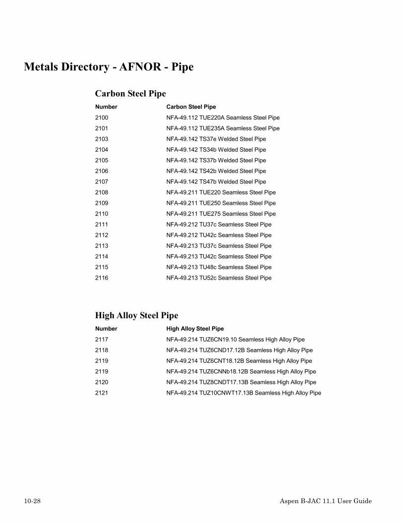
10-28 Aspen B-JAC 11.1 User Guide
Metals Directory - AFNOR - Pipe
Carbon Steel PipeNumber Carbon Steel Pipe
2100 NFA-49.112 TUE220A Seamless Steel Pipe
2101 NFA-49.112 TUE235A Seamless Steel Pipe
2103 NFA-49.142 TS37e Welded Steel Pipe
2104 NFA-49.142 TS34b Welded Steel Pipe
2105 NFA-49.142 TS37b Welded Steel Pipe
2106 NFA-49.142 TS42b Welded Steel Pipe
2107 NFA-49.142 TS47b Welded Steel Pipe
2108 NFA-49.211 TUE220 Seamless Steel Pipe
2109 NFA-49.211 TUE250 Seamless Steel Pipe
2110 NFA-49.211 TUE275 Seamless Steel Pipe
2111 NFA-49.212 TU37c Seamless Steel Pipe
2112 NFA-49.212 TU42c Seamless Steel Pipe
2113 NFA-49.213 TU37c Seamless Steel Pipe
2114 NFA-49.213 TU42c Seamless Steel Pipe
2115 NFA-49.213 TU48c Seamless Steel Pipe
2116 NFA-49.213 TU52c Seamless Steel Pipe
High Alloy Steel PipeNumber High Alloy Steel Pipe
2117 NFA-49.214 TUZ6CN19.10 Seamless High Alloy Pipe
2118 NFA-49.214 TUZ6CND17.12B Seamless High Alloy Pipe
2119 NFA-49.214 TUZ6CNT18.12B Seamless High Alloy Pipe
2119 NFA-49.214 TUZ6CNNb18.12B Seamless High Alloy Pipe
2120 NFA-49.214 TUZ8CNDT17.13B Seamless High Alloy Pipe
2121 NFA-49.214 TUZ10CNWT17.13B Seamless High Alloy Pipe

Aspen B-JAC 11.1 User Guide 10-29
Metals Directory - AFNOR - Plate
Carbon Steel PlateNumber Carbon Steel Plate
2212 NFA-35.501 E24-2 Steel Plate
2213 NFA-35.501 E24-3 Steel Plate
2214 NFA-35.501 E24-4 Steel Plate
2200 NFA-36.205 A37-CP Steel Plate
2201 NFA-36.205 A37-AP Steel Plate
2202 NFA-36.205 A37-FP Steel Plate
2203 NFA-36.205 A42-CP Steel Plate
2204 NFA-36.205 A42-AP Steel Plate
2205 NFA-36.205 A42-FP Steel Plate
2206 NFA-36.205 A48-CP Steel Plate
2207 NFA-36.205 A48-AP Steel Plate
2208 NFA-36.205 A48-FP Steel Plate
2209 NFA-36.205 A52-CP Steel Plate
2210 NFA-36.205 A52-AP Steel Plate
2211 NFA-36.205 A52-FP Steel Plate

10-30 Aspen B-JAC 11.1 User Guide
High Alloy Steel PlateNumber High Alloy Steel Plate
2233 NFA-36.209 Z1CN18.12 High Alloy Steel Plate
2234 NFA-36.209 Z1CNS17.15 High Alloy Steel Plate
2215 NFA-36.209 Z3CN18.10 High Alloy Steel Plate
2235 NFA-36.209 Z4CN19.10 High Alloy Steel Plate
2216 NFA-36.209 Z6CN18.09 High Alloy Steel Plate
2217 NFA-36.209 Z7CN18.09 High Alloy Steel Plate
2220 NFA-36.209 Z6CNNb18.10 High Alloy Steel Plate
2218 NFA-36.209 Z6CNT18.10HT High Alloy Steel Plate
2219 NFA-36.209 Z6CNT18.10BT High Alloy Steel Plate
2229 NFA-36.209 Z3CN18.10Az High Alloy Steel Plate
2230 NFA-36.209 Z6CN19.09Az High Alloy Steel Plate
2221 NFA-36.209 Z3CND17.11.02 High Alloy Steel Plate
2227 NFA-36.209 Z3CND17.12.03 High Alloy Steel Plate
2224 NFA-36.209 Z3CND18.12.03 High Alloy Steel Plate
2228 NFA-36.209 Z3CND19.15.04 High Alloy Steel Plate
2236 NFA-36.209 Z4CND18.12.03 High Alloy Steel Plate
2225 NFA-36.209 Z6CND18.12.03 High Alloy Steel Plate
2222 NFA-36.209 Z7CND17.11.02 High Alloy Steel Plate
2226 NFA-36.209 Z6CNDNb18.12 High Alloy Steel Plate
2223 NFA-36.209 Z6CNDT17.12 High Alloy Steel Plate
2237 NFA-36.209 Z3CND17.11Az High Alloy Steel Plate
2231 NFA-36.209 Z3CND17.12Az High Alloy Steel Plate
2238 NFA-36.209 Z3CND18.14.05Az High Alloy Steel Plate
2239 NFA-36.209 Z3CND19.14Az High Alloy Steel Plate
2232 NFA-36.209 Z4CMN18.08.07Az High Alloy Steel Plate
2233

Aspen B-JAC 11.1 User Guide 10-31
Metals Directory - AFNOR - Bolting
Low Alloy Steel BoltingNumber Low Alloy Steel Bolting
2600 NFA-35.558 25CD4 Alloy Steel Bolting
2601 NFA-35.558 42CDV4 Alloy Steel Bolting
Metals - Directory - AFNOR - Forging
Carbon Steel ForgingNumber Carbon Steel Forging
2400 NFA-36.601 A37-CP Steel Forging
2401 NFA-36.601 A37-AP Steel Forging
2402 NFA-36.601 A37-FP Steel Forging
2403 NFA-36.601 A42-CP Steel Forging
2404 NFA-36.601 A42-AP Steel Forging
2405 NFA-36.601 A42-FP Steel Forging
2406 NFA-36.601 A48-CP Steel Forging
2407 NFA-36.601 A48-AP Steel Forging
2408 NFA-36.601 A48-FP Steel Forging
2409 NFA-36.601 A52-CP Steel Forging
2410 NFA-36.601 A52-AP Steel Forging
2411 NFA-36.601 A52-FP Steel Forging

10-32 Aspen B-JAC 11.1 User Guide
High Alloy Steel ForgingNumber High Alloy Steel Forging
2412 NFA-36.607 Z2CN18.10 High Alloy Steel Forging
2413 NFA-36.607 Z5CN18.09 High Alloy Steel Forging
2414 NFA-36.607 Z6CN18.09 High Alloy Steel Forging
2416 NFA-36.607 Z6CNT18.10 High Alloy Steel Forging
2417 NFA-36.607 Z6CNNb18.10 High Alloy Steel Forging
2418 NFA-36.607 Z2CND17.12 High Alloy Steel Forging
2419 NFA-36.607 Z6CND17.11 High Alloy Steel Forging
2420 NFA-36.607 Z6CNDT17.12 High Alloy Steel Forging
2422 NFA-36.607 Z2CND18.13 High Alloy Steel Forging
2423 NFA-36.607 Z6CND18.13 High Alloy Steel Forging

Aspen B-JAC 11.1 User Guide 10-33
Metals Directory - AFNOR - Gasket
GasketsNumber Gasket Material
2324 Compressed Asbestos 1 mm Thk.
2301 Compresses Asbestos 2 mm Thk.
2302 Compressed Asbestos 3 mm Thk.
2314 Solid Teflon 1 mm Thk.
2316 Solid Teflon 2 mm Thk.
2317 Solid Teflon 3 mm Thk.
2318 Spiral-Wound Metal Asbestos Monel
2303 Spiral-Wound Metal Asbestos Carbon Steel
2304 Spiral-Wound Metal Asbestos Stainless Steel
2305 Flat Metal Jacket Asbestos Soft Copper
2319 Flat Metal Jacket Asbestos Brass
2320 Flat Metal Jacket Asbestos Soft Steel
2306 Flat Metal Jacket Asbestos Iron
2307 Flat Metal Jacket Asbestos Monel
2308 Flat Metal Jacket Asbestos 4-6% Chrome
2309 Flat Metal Jacket Asbestos Stainless Steel
2310 Solid Flat Metal Soft Copper
2311 Solid Flat Metal Iron
2312 Solid Flat Metal Monel
2313 Solid Flat Metal Stainless Steel
2321 Solid Flat Metal Soft Brass
2322 Solid Flat Metal Soft Steel
2323 Solid Flat Metal 4-6% Chrome
2325 Elastomers 75A or Higher Shore Durometer
2326 Self-Energizing Types
2327 Ring Joint Iron or Soft Steel
2328 Ring Joint Monel or 4-6% Chrome
2329 Ring Joint Stainless Steel

10-34 Aspen B-JAC 11.1 User Guide
Metals Directory - AFNOR - Tube
Carbon Steel TubeNumber Carbon Steel Tube
2700 NFA-49.215 TU37c Seamless Steel Tube
2701 NFA-49.215 TU42c Seamless Steel Tube
2702 NFA-49.215 TU48c Seamless Steel Tube
Low Alloy Steel TubeNumber Low Alloy Steel Tube
2703 NFA-49.215 TU15D3 Seamless Low Alloy Tube
2704 NFA-49.215 TU15CD2.05 Seamless Low Alloy Tube
2705 NFA-49.215 TU10CD5.05 Seamless Low Alloy Tube
2706 NFA-49.215 TU10CD9.10 Seamless Low Alloy Tube
2707 NFA-49.215 TUZ10CD5.05 Seamless Low Alloy Tube
2708 NFA-49.215 TUZ10CD9 Seamless Low Alloy Tube
High Alloy Steel TubeNumber High Alloy Steel Tube
2715 NFA-49.217 TUZ12C13 Seamless High Alloy Tube
2716 NFA-49.217 TUZ10C17 Seamless High Alloy Tube
2710 NFA-49.217 TUZ2CN18.10 Seamless High Alloy Tube
2711 NFA-49.217 TUZ6CN18.09 Seamless High Alloy Tube
2712 NFA-49.217 TUZ6CNT18.10 Seamless High Alloy Tube
2713 NFA-49.217 TUZ2CND17.12 Seamless High Alloy Tube
2714 NFA-49.217 TUZ6CND17.11 Seamless High Alloy Tube
2717 NFA-49.247 TSZ2CN18.10 Welded High Alloy Tube
2718 NFA-49.247 TSZ6CN18.09 Welded High Alloy Tube
2719 NFA-49.247 TSZ6CNT18.10 Welded High Alloy Tube
2720 NFA-49.247 TSZ2CND17.12 Welded High Alloy Tube
2721 NFA-49.247 TSZ6CND17.11 Welded High Alloy Tube
2722 NFA-49.247 TSZ2CND19.15 Welded High Alloy Tube

Aspen B-JAC 11.1 User Guide 10-35
Metals Directory - DIN - Generic
Generic MaterialNumber Generic Material
1 Carbon Steel
2 Low Alloy Steel C 1/2 Mo
3 Low Alloy Steel 1/2 Cr 1/2 Mo
4 Low Alloy Steel Cr 1/2 Mo
5 Low Alloy Steel 1 1/4 Cr 1/2 Mo
6 High Alloy Steel Grade 304
7 High Alloy Steel Grade 304L
8 High Alloy Steel Grade 316
9 High Alloy Steel Grade 316L
13 High Alloy Steel Grade 410
15 Nickel Low Carbon Alloy 201
16 Nickel Alloy 400 (Monel)
17 Nickel Alloy 600 (Inconel)
19 Nickel Alloy 825 (Incoloy)
25 Copper-Nickel 70/30 Alloy CDA 715
26 Copper-Nickel 90/10 Alloy CDA 706
33 Zirconium

10-36 Aspen B-JAC 11.1 User Guide
Metals Directory - DIN - Pipe
Pipe - Alloyed and Non-Alloyed Steel - Seamless - AD W4Number Pipe Alloyed and NonAlloyed Steel Seamless AD W4
3202 1.0254 - St 37.0 - DIN 1629
3208 1.0255 - St 37.4 - DIN 1630
3204 1.0256 - St 44.0 - DIN 1629
3210 1.0257 - St 44.4 - DIN 1630
3230 1.0305 - St 35.8 - DIN 17175
3214 1.0356 - TTSt 35 N - DIN 17173
3216 1.0356 - TTSt 35 V - DIN 17173
3232 1.0405 - St 45.8 - DIN 17175
3206 1.0421 - St 52.0 - DIN 1629
3248 1.0462 - WStE 255 - DIN 17179
3234 1.0481 - 17 Mn 4 - DIN 17175
3236 1.0482 - 19 Mn 5 - DIN 17175
3250 1.0487 - WStE 285 - DIN 17179
3252 1.0565 - WStE 355 - DIN 17179
3212 1.0581 - St 52.4 - DIN 1630
3246 1.4922 - X 20 CrMoV 12 1 - DIN 17175
3238 1.5415 - 15 Mo 3 - DIN 17175
3224 1.5637 - 10 Ni 14 - DIN 17173
3228 1.5662 - X 8 Ni 9 - DIN 17173
3226 1.5680 - 12 Ni 19 - DIN 17173
3220 1.6212 - 11 MnNi 5 3 - DIN 17173
3222 1.6217 - 13 MnNi 6 3 - DIN 17173
3218 1.7219 - 26 CrMo 4 - DIN 17173
3240 1.7335 - 13 CrMo 4 4 - DIN 17175
3242 1.7380 - 10 CrMo 9 10 - DIN 17175
3244 1.7715 - 14 MoV 6 3 - DIN 17175
3254 1.8932 - WStE 420 - DIN 17179
3256 1.8935 - WStE 460 - DIN 17179
3287 1.0315 - St 37.8 - DIN 17177
3289 1.0498 - St 42.8 - DIN 17177
3291 1.5415 - 15 MoV 3 - DIN 17177
3257 1.8935 - WStE 460 - DIN 17178

Aspen B-JAC 11.1 User Guide 10-37
Pipe - Stainless Steel - Welded - AD W2 - DIN 17457Number Pipe - Stainless Steel - Welded - AD W2 - DIN 17457
3261 1.4301 - X 5 CrNi 18 10 - DIN 17457
3263 1.4306 - X 2 CrNi 19 11 - DIN 17457
3265 1.4331 - X 2 CrNiN 18 10 - DIN 17457
3271 1.4401 - X 5 CrNiMo 17 12 2 - DIN 17457
3273 1.4404 - X 2 CrNiMo 17 13 2 - DIN 17457
3279 1.4429 - X 2 CrNiMoN 17 13 3 - DIN 17457
3281 1.4435 - X 2 CrNiMoN 17 13 3 - DIN 17457
3283 1.4436 - X 5 CrNiMo 17 13 3 - DIN 17457
3285 1.4439 - X 2 CrNiMoN 17 13 5 - DIN 17457
3267 1.4541 - X 6 CrNiTi 18 10 - DIN 17457
3269 1.4550 - X 6 CrNiNb 18 10 - DIN 17457
3275 1.4571 - X 6 CrNiMoTi 17 12 2 - DIN 17457
Pipe - Nickel and Nickel Alloy - VdTÜVNumber Pipe - Nickel and Nickel Alloy - VdTÜV
3292 2.4068 - Nickel 201 - VdTÜV 345
3288 2.4360 - Monel 400 - VdTÜV 263
3290 2.4816 - Inconel 600 - VdTÜV 305
3294 2.4856 - VdTÜV 499
3286 2.4858 - Incoloy 825 - VdTÜV 432

10-38 Aspen B-JAC 11.1 User Guide
Metals Directory - DIN - Plate
Plates - Alloyed and Non-Alloyed Steel - AD W1Number Plates - Alloyed and Non-Alloyed Steel - AD W13000 1.0035 - St 33 - DIN 17100
3001 1.0036 - USt 37-2 - DIN 17100
3002 1.0037 - St 37-2 - DIN 17100
3003 1.0038 - RSt 37-2 - DIN 17100
3005 1.0044 - St 44-2 - DIN 17100
3008 1.0050 - St 50-2 - DIN 17100
3009 1.0060 - St 60-2 - DIN 17100
3010 1.0070 - St 70-2 - DIN 17100
3004 1.0116 - St 37-3 - DIN 17100
3006 1.0144 - St 44-3 - DIN 17100
3020 1.0345 - H I - DIN 17155
3021 1.0425 - H II - DIN 17155
3011 1.0462 - WStE 255 - DIN 17102
3024 1.0473 - 19 Mn 6 - DIN 17155
3023 1.0481 - 17 Mn 4 - DIN 17155
3012 1.0487 - WStE 285 - DIN 17102
3013 1.0506 - WStE 315 - DIN 17102
3014 1.0565 - WStE 355 - DIN 17102
3007 1.0570 - St 52-3 - DIN 17100
3025 1.5415 - 15 Mo 3 - DIN 17155
3032 1.5637 - 10 Ni 14 - DIN 17280
3035 1.5662 - X 8 Ni 9 - DIN 17280
3033 1.5680 - 12 Ni 19 - DIN 17280
3029 1.6212 - 11 MnNi 5 3 - DIN 17280
3030 1.6217 - 13 MnNi 6 3 - DIN 17280
3031 1.6228 - 14 NiMn 6 - DIN 17280
3034 1.6349 - X 7 NiMo 6 - DIN 17280
3028 1.7219 - 26 CrMo 4 - DIN 17280
3026 1.7335 - 13 CrMo 4 4 - DIN 17155
3015 1.8930 - WStE 380 - DIN 17102
3016 1.8932 - WStE 420 - DIN 17102
3017 1.8935 - WStE 460 - DIN 17102
3018 1.8937 - WStE 500 - DIN 17102
3019 1.8937 - WStE 500 - DIN 17102

Aspen B-JAC 11.1 User Guide 10-39
Plates - Stainless Steel - AD W2 - DIN 17440Number Plates - Stainless Steel - AD W2 - DIN 17440
3036 1.4000 - X 6 Cr 13 - DIN 17440
3037 1.4002 - X 6 CrAl 13 - DIN 17440
3038 1.4006 - X 10 Cr 13 - DIN 17440
3062 1.4016 - X 6 Cr 17 - DIN 17440
3040 1.4021 - X 20 Cr 13 - DIN 17440
3039 1.4024 - X 15 Cr 13 - DIN 17440
3041 1.4028 - X 30 Cr 13 - DIN 17440
3042 1.4031 - X 38 Cr 13 - DIN 17440
3043 1.4034 - X 48 Cr 13 - DIN 17440
3066 1.4057 - X CrNi 17 2 - DIN 17440
3065 1.4104 - X 12 CrMoS 17 - DIN 17440
3064 1.4105 - X 4 CrMoS 18 - DIN 17440
3044 1.4116 - X 45 CrMoV 15 - DIN 17440
3045 1.4301 - X 5 CrNi 8 10 - DIN 17440
3046 1.4303 - X 5 CrNi 18 12 - DIN 17440
3047 1.4305 - X 10 CrNiS 18 9 - DIN 17440
3048 1.4306 - X 2 CrNi 19 11 - DIN 17440
3049 1.4311 - X 2 CrNiN 18 10 - DIN 17440
3052 1.4401 - X 5 CrNiMo 17 12 2 - DIN 17440
3053 1.4404 - X 2 CrNiMo 17 13 2 - DIN 17440
3054 1.4406 - X 2 CrNiMoN 17 12 2 - DIN 17440
3057 1.4429 - X 2 CrNiMoN 17 13 3 - DIN 17440
3058 1.4435 - X 2 CrNiMo 18 14 3 - DIN 17440
3059 1.4436 - X 5 CrNiMo 17 13 3 - DIN 17440
3060 1.4438 - X 2 CrNiMo 18 16 4 - DIN 17440
3061 1.4439 - X 2 CrNiMoN 17 13 5 - DIN 17440
3063 1.4510 - X 6 CrTi 17 - DIN 17440
3050 1.4541 - X 6 CrNiTi 18 10 - DIN 17440
3051 1.4550 - X 6 CrNiNb 18 10 - DIN 17440
3055 1.4571 - X 6 CrNiMoTi 17 12 2 - DIN 17440
3056 1.4580 - X 6 CrNiMoNb 17 12 2 - DIN 17440

10-40 Aspen B-JAC 11.1 User Guide
Plates - Copper and Copper Alloy - AD W6/2Number Plates - Copper and Copper Alloy - AD W6/2
3070 2.0090.10 - SF-Cu F20 - AD W6/2
3071 2.0872.19 - CuNi10Fe1Mn F30 - AD W6/2
3072 2.0882.19 - CuNi30Fe1Mn F35 - AD W6/2
Plates - Nickel and Nickel Alloy - VdTÜVNumber Plates - Nickel and Nickel Alloy - VdTšV
3076 2.4068 - Nickel 201 - VdTÜV 345
3074 2.4360 - Monel 400 - VdTÜV 263
3075 2.4816 - Inconel 600 - VdTÜV 305
3077 2.4856 - VdTÜV 499
Metals Directory - DIN - Bolting
Bolts - DIN 17240Number Bolts - DIN 17240
3701 1.1181 - Ck 35
3707 1.4913 - X 19 CrMoVNbN 11 1
3706 1.4923 - X 22 CrMoV 12 1
3708 1.4986 - X 8 CrNiMoBNb 16 16
3702 1.7258 - 24 CrMo 5
3704 1.7709 - 21 CrMoV 5 7
3705 1.7711 - 40 CrMoV 4 7
3709 2.4952 - NiCr20TiAl
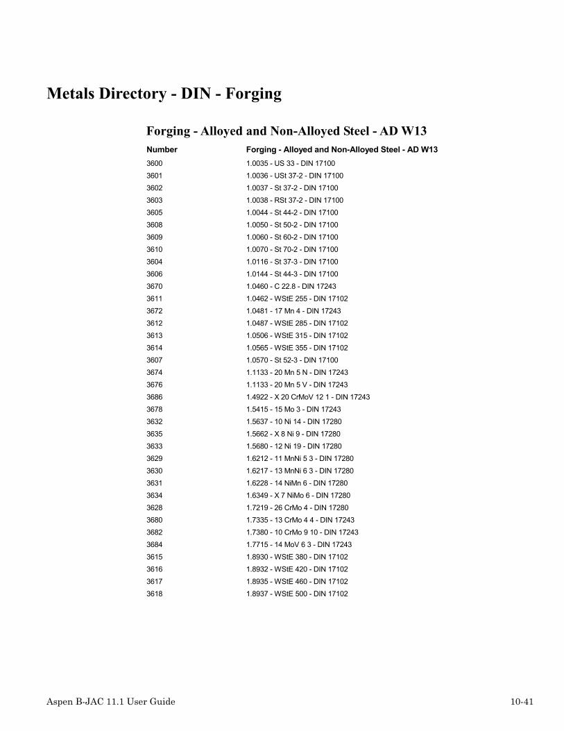
Aspen B-JAC 11.1 User Guide 10-41
Metals Directory - DIN - Forging
Forging - Alloyed and Non-Alloyed Steel - AD W13Number Forging - Alloyed and Non-Alloyed Steel - AD W133600 1.0035 - US 33 - DIN 171003601 1.0036 - USt 37-2 - DIN 171003602 1.0037 - St 37-2 - DIN 171003603 1.0038 - RSt 37-2 - DIN 171003605 1.0044 - St 44-2 - DIN 171003608 1.0050 - St 50-2 - DIN 171003609 1.0060 - St 60-2 - DIN 171003610 1.0070 - St 70-2 - DIN 171003604 1.0116 - St 37-3 - DIN 171003606 1.0144 - St 44-3 - DIN 171003670 1.0460 - C 22.8 - DIN 172433611 1.0462 - WStE 255 - DIN 171023672 1.0481 - 17 Mn 4 - DIN 172433612 1.0487 - WStE 285 - DIN 171023613 1.0506 - WStE 315 - DIN 171023614 1.0565 - WStE 355 - DIN 171023607 1.0570 - St 52-3 - DIN 171003674 1.1133 - 20 Mn 5 N - DIN 172433676 1.1133 - 20 Mn 5 V - DIN 172433686 1.4922 - X 20 CrMoV 12 1 - DIN 172433678 1.5415 - 15 Mo 3 - DIN 172433632 1.5637 - 10 Ni 14 - DIN 172803635 1.5662 - X 8 Ni 9 - DIN 172803633 1.5680 - 12 Ni 19 - DIN 172803629 1.6212 - 11 MnNi 5 3 - DIN 172803630 1.6217 - 13 MnNi 6 3 - DIN 172803631 1.6228 - 14 NiMn 6 - DIN 172803634 1.6349 - X 7 NiMo 6 - DIN 172803628 1.7219 - 26 CrMo 4 - DIN 172803680 1.7335 - 13 CrMo 4 4 - DIN 172433682 1.7380 - 10 CrMo 9 10 - DIN 172433684 1.7715 - 14 MoV 6 3 - DIN 172433615 1.8930 - WStE 380 - DIN 171023616 1.8932 - WStE 420 - DIN 171023617 1.8935 - WStE 460 - DIN 171023618 1.8937 - WStE 500 - DIN 17102

10-42 Aspen B-JAC 11.1 User Guide
Forging - Stainless Steel - AD W2 - DIN 17440Number Forging - Stainless Steel - AD W2 - DIN 17440
3636 1.4000 - X 6 Cr 13 - DIN 17440
3637 1.4002 - X 6 CrAl 13 - DIN 17440
3638 1.4006 - X 10 Cr 13 - DIN 17440
3662 1.4016 - X 6 Cr 17 - DIN 17440
3640 1.4021 - X 20 Cr 13 - DIN 17440
3639 1.4024 - X 15 Cr 13 - DIN 17440
3641 1.4028 - X 30 Cr 13 - DIN 17440
3642 1.4031 - X 38 Cr 13 - DIN 17440
3643 1.4034 - X 48 Cr 13 - DIN 17440
3666 1.4057 - X CrNi 17 2 - DIN 17440
3665 1.4104 - X 12 CrMoS 17 - DIN 17440
3664 1.4105 - X 4 CrMoS 18 - DIN 17440
3644 1.4116 - X 45 CrMoV 15 - DIN 17440
3645 1.4301 - X 5 CrNi 8 10 - DIN 17440
3646 1.4303 - X 5 CrNi 18 12 - DIN 17440
3647 1.4305 - X 10 CrNiS 18 9 - DIN 17440
3648 1.4306 - X 2 CrNi 19 11 - DIN 17440
3649 1.4311 - X 2 CrNiN 18 10 - DIN 17440
3652 1.4401 - X 5 CrNiMo 17 12 2 - DIN 17440
3653 1.4404 - X 2 CrNiMo 17 13 2 - DIN 17440
3654 1.4406 - X 2 CrNiMoN 17 12 2 - DIN 17440
3657 1.4429 - X 2 CrNiMoN 17 13 3 - DIN 17440
3658 1.4435 - X 2 CrNiMo 18 14 3 - DIN 17440
3659 1.4436 - X 5 CrNiMo 17 13 3 - DIN 17440
3660 1.4438 - X 2 CrNiMo 18 16 4 - DIN 17440
3661 1.4439 - X 2 CrNiMoN 17 13 5 - DIN 17440
3663 1.4510 - X 6 CrTi 17 - DIN 17440
3650 1.4541 - X 6 CrNiTi 18 10 - DIN 17440
3651 1.4550 - X 6 CrNiNb 18 10 - DIN 17440
3655 1.4571 - X 6 CrNiMoTi 17 12 2 - DIN 17440
3656 1.4580 - X 6 CrNiMoNb 17 12 2 - DIN 17440

Aspen B-JAC 11.1 User Guide 10-43
Metals - Directory - DIN - Gasket
GasketsNumber Gaskets
3312 Blechummantelte Dichtung - Al
3313 Blechummantelte Dichtung - Cu-Ms
3314 Blechummantelte Dichtung - weicher Stahl
3300 Flachdichtung - PTFE
3301 Flachdichtung - It - DIN 2505 (4/90)
3307 Flachdichtung - It - DIN 2505 (1/86)
3302 Flachdichtung - It PTFE-ummantelt
3303 Graphit mit Verstürkung - DIN 2505
3306 Linsendichtung - DIN 2696
3305 Metall-Flachdichtung - Stahl - St 35
3308 Spiral-Asbestdichtung - unlegierter Stahl
3309 Welldichtring - Al
3310 Welldichtring - Cu-Ms
3311 Welldichtring - weicher Stahl

10-44 Aspen B-JAC 11.1 User Guide
Metals Directory - DIN - Tube
Tubes - Alloyed and Non-Alloyed Steel - Seamless - AD W4Number TubesAlloyed and NonAlloyed Steel Seamless AD W4
3401 1.0253 - USt 37.0 - DIN 1626
3402 1.0254 - St 37.0 - DIN 1629
3408 1.0255 - St 37.4 - DIN 1630
3404 1.0256 - St 44.0 - DIN 1629
3410 1.0257 - St 44.4 - DIN 1630
3430 1.0305 - St 35.8 - DIN 17175
3414 1.0356 - TTSt 35 N - DIN 17173
3416 1.0356 - TTSt 35 V - DIN 17173
3432 1.0405 - St 45.8 - DIN 17175
3406 1.0421 - St 52.0 - DIN 1629
3448 1.0462 - WStE 255 - DIN 17179
3434 1.0481 - 17 Mn 4 - DIN 17175
3436 1.0482 - 19 Mn 5 - DIN 17175
3450 1.0487 - WStE 285 - DIN 17179
3452 1.0565 - WStE 355 - DIN 17179
3412 1.0581 - St 52.4 - DIN 1630
3446 1.4922 - X 20 CrMoV 12 1 - DIN 17175
3438 1.5415 - 15 Mo 3 - DIN 17175
3424 1.5637 - 10 Ni 14 - DIN 17173
3428 1.5662 - X 8 Ni 9 - DIN 17173
3426 1.5680 - 12 Ni 19 - DIN 17173
3420 1.6212 - 11 MnNi 5 3 - DIN 17173
3422 1.6217 - 13 MnNi 6 3 - DIN 17173
3418 1.7219 - 26 CrMo 4 - DIN 17173
3440 1.7335 - 13 CrMo 4 4 - DIN 17175
3442 1.7380 - 10 CrMo 9 10 - DIN 17175
3444 1.7715 - 14 MoV 6 3 - DIN 17175
3454 1.8932 - WStE 420 - DIN 17179
3456 1.8935 - WStE 460 - DIN 17179
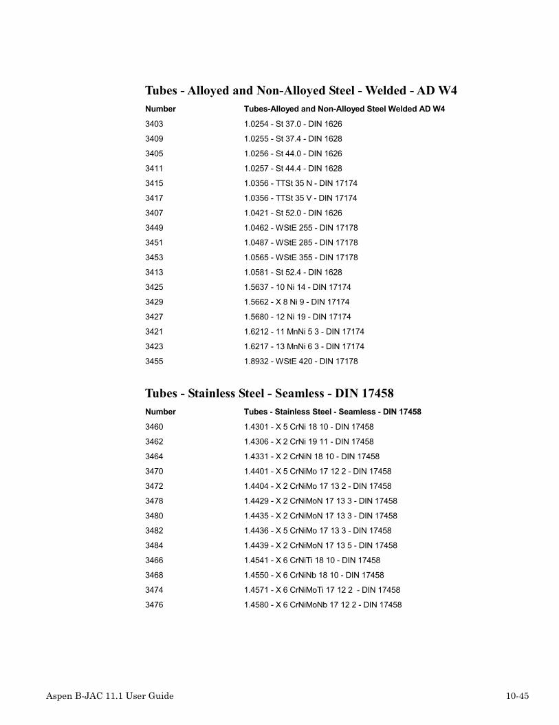
Aspen B-JAC 11.1 User Guide 10-45
Tubes - Alloyed and Non-Alloyed Steel - Welded - AD W4Number Tubes-Alloyed and Non-Alloyed Steel Welded AD W4
3403 1.0254 - St 37.0 - DIN 1626
3409 1.0255 - St 37.4 - DIN 1628
3405 1.0256 - St 44.0 - DIN 1626
3411 1.0257 - St 44.4 - DIN 1628
3415 1.0356 - TTSt 35 N - DIN 17174
3417 1.0356 - TTSt 35 V - DIN 17174
3407 1.0421 - St 52.0 - DIN 1626
3449 1.0462 - WStE 255 - DIN 17178
3451 1.0487 - WStE 285 - DIN 17178
3453 1.0565 - WStE 355 - DIN 17178
3413 1.0581 - St 52.4 - DIN 1628
3425 1.5637 - 10 Ni 14 - DIN 17174
3429 1.5662 - X 8 Ni 9 - DIN 17174
3427 1.5680 - 12 Ni 19 - DIN 17174
3421 1.6212 - 11 MnNi 5 3 - DIN 17174
3423 1.6217 - 13 MnNi 6 3 - DIN 17174
3455 1.8932 - WStE 420 - DIN 17178
Tubes - Stainless Steel - Seamless - DIN 17458Number Tubes - Stainless Steel - Seamless - DIN 17458
3460 1.4301 - X 5 CrNi 18 10 - DIN 17458
3462 1.4306 - X 2 CrNi 19 11 - DIN 17458
3464 1.4331 - X 2 CrNiN 18 10 - DIN 17458
3470 1.4401 - X 5 CrNiMo 17 12 2 - DIN 17458
3472 1.4404 - X 2 CrNiMo 17 13 2 - DIN 17458
3478 1.4429 - X 2 CrNiMoN 17 13 3 - DIN 17458
3480 1.4435 - X 2 CrNiMoN 17 13 3 - DIN 17458
3482 1.4436 - X 5 CrNiMo 17 13 3 - DIN 17458
3484 1.4439 - X 2 CrNiMoN 17 13 5 - DIN 17458
3466 1.4541 - X 6 CrNiTi 18 10 - DIN 17458
3468 1.4550 - X 6 CrNiNb 18 10 - DIN 17458
3474 1.4571 - X 6 CrNiMoTi 17 12 2 - DIN 17458
3476 1.4580 - X 6 CrNiMoNb 17 12 2 - DIN 17458
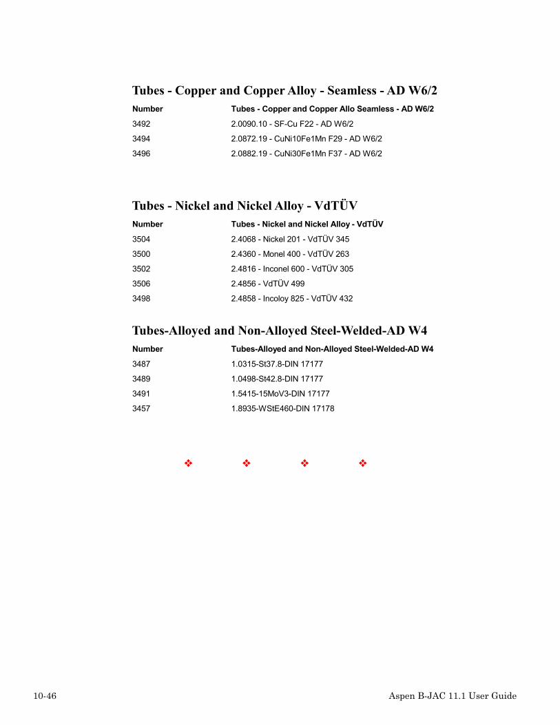
10-46 Aspen B-JAC 11.1 User Guide
Tubes - Copper and Copper Alloy - Seamless - AD W6/2Number Tubes - Copper and Copper Allo Seamless - AD W6/2
3492 2.0090.10 - SF-Cu F22 - AD W6/2
3494 2.0872.19 - CuNi10Fe1Mn F29 - AD W6/2
3496 2.0882.19 - CuNi30Fe1Mn F37 - AD W6/2
Tubes - Nickel and Nickel Alloy - VdTÜVNumber Tubes - Nickel and Nickel Alloy - VdTÜV
3504 2.4068 - Nickel 201 - VdTÜV 345
3500 2.4360 - Monel 400 - VdTÜV 263
3502 2.4816 - Inconel 600 - VdTÜV 305
3506 2.4856 - VdTÜV 499
3498 2.4858 - Incoloy 825 - VdTÜV 432
Tubes-Alloyed and Non-Alloyed Steel-Welded-AD W4Number Tubes-Alloyed and Non-Alloyed Steel-Welded-AD W4
3487 1.0315-St37.8-DIN 17177
3489 1.0498-St42.8-DIN 17177
3491 1.5415-15MoV3-DIN 17177
3457 1.8935-WStE460-DIN 17178
❖ ❖ ❖ ❖

Aspen B-JAC 11.1 User Guide 11-1
11 Primetals
Introduction
Primetal is a program that allows you to build and maintain your own databank of materialswhich supplements the materials in the Metals databank.
The material can be in the form of plate, pipe, tube, forging, coupling, bolt, or gasket. Onceyou assign a material name and store the material properties, you can then use the newmaterial name in any of the Aspen B-JAC programs which allow specific material names(Hetran, Teams, Metals).
The Primetal program provides the following functions:• Add a material• Modify the properties of a material• Delete a material• Display or print a list of materials• Display or print the properties of a material
This program does not require an input data file, since all of the data is stored in the databankitself. You specify the input data directly into the Primetal program when you run it. Theinput data can be specified in either U.S., SI, or Metric units and is divided into threesections:• Names• Constant properties• Temperature dependent properties
The names are:• Full name (up to 78 characters)• Short name (up to 39 characters) for the mechanical design output• Very short name (up to 24 characters) for the bill of materials

11-2 Aspen B-JAC 11.1 User Guide
The constant properties include:• Material type and class• Price and currency• Equivalent material numbers for pipe, plate, forging, coupling• Density• Minimum thickness• P number and group number• External pressure chart• Minimum tensile and yield strengths• Maximum thickness for x-ray exemption• Poisson ratio• Minimum and maximum diameter for validity
The temperature dependent properties include:• Thermal conductivity• Allowable stress• Yield strength• Coefficient of thermal expansion• Modulus of elasticity• Stress intensity• Tensile strength
For each of the temperature dependent properties, you can specify from 2 to 21 points,starting from a specified starting temperature, then according to a specified temperatureincrement. Each property should also have minimum and maximum temperatures. If a value isnot available for one or more of the temperature points, you can specify a zero (or leave itblank) and the databank routine will automatically interpolate using the closest specifiedvalues.
Currency
This item refers to the currency of the values in the cost files. The original selections are:
1= $US 2= $Canadian 3= French Franc 4= British Pound
5= Belgium Franc 6= Deutch Mark 7= Italian Lire 8= Yen
The default values are already in US dollars. I recommend to always us �1� (USDollar).
The user can enter the Korean Won in the UOM Control (Unit of Measure control - the usercan enter any currency here). Go to Tools > Data Maintenance > Units of Measure > UnitsMaintenance. Fill out the new currency information. Save the changes. From this pointforward, the user can convert to the new currency. Also, using one of three customizableunit-sets, the user can default to a currency and other special units.

Aspen B-JAC 11.1 User Guide 11-3
Material Type
The number designator used by the program for the material type are:
1= seamless pipe 101= forging (SP = Seamless pipe, ST = Seamless tube, etc.)
2= seamless tube 102= coupling
25= welded pipe 151= gasket
26= welded tube 165= bolt
51= plate
Material Class
The number designator used by the program for the material class are:
1= Carbon Steel 2= Low Alloy Steel
3= High Alloy Steel 4= Ni or Ni Alloy
5= Titanium Alloy 6= Cu Alloy HT (HT=High Tensile)
7= Nickel Alloy B,C, or G 8= Zirconium
9= Nickel Alloy HT 10= Cu or Cu Alloy
0=Gasket
The material type and class is important when the user enters his/her own materials.

11-4 Aspen B-JAC 11.1 User Guide
External Pressure Chart Reference
An external pressure chart reference, ASME Section II, Part D, must be provided for externalpressure calculations. The correlation is determine the number to be entered is as follows:
Material database external pressure chart reference number = X*100 + Y
Where X represents the material type:
X=1 for CS
X=2 for HA
X=3 for NF
X=4 for HT
` X=5 for CI
X=6 for CD
Where Y = chart number
Examples: Chart CS-3 = 103 ( X=1, Y=3 )
Chart NFN-16 (old reference was UNF-28.40) = 340 ( X=3, Y=40 )

Aspen B-JAC 11.1 User Guide 11-5
Example Input to Primetals
Steps to create a private material
1. Open Materials Database by selecting Tools / Data Maintenance / Material Database formthe B-JAC User Interface.
2. Open one of the existing Code material databases, such as ASME, from the DatabaseMenu option.
3. Select a similar material in the Code database to the private material you wish to create.This will act as a template for the new material.
4. Select Property / Copy to copy the contents into the buffer.
5. Select Database / User.

11-6 Aspen B-JAC 11.1 User Guide
6. If no user materials exist in the database, you will be asked if you wish to create a newmaterial. Answer Yes and set the user database number for the new material. Your newmaterial in the database will be displayed with the existing properties being used as atemplate. Proceed to step 8.
7. If user materials already exist, your existing database items will be displayed. To copythe template properties, select Property and Paste and then select a number new materialreference number.
8. Now modify the template properties to generate your new material. If you have selected avery similar material, you may only need to modify the material names and the allowabledesign stresses.
9. Once all changes have been made, select Save to update the database. Now this new usermaterial may be referenced from any of the B-JAC programs.
❖ ❖ ❖ ❖

Aspen B-JAC 11.1 User Guide 12-1
12 Newcost Database
IntroductionNewcost is a database maintenance program, designed to modify and/or print the contents ofthe labor and material cost files associated with the Aspen B-JAC programs which addresscost estimation (Teams, Qchex, and Hetran).
B-JAC supplies a standard database with each version of the program. When you make anychanges to the database, your changes will always override any values in the standarddatabase.
To start the Newcost database, first change your working directory to where you want themodified database to reside. This can be the same directory as the Aspen B-JAC programs orother user sub-directories. When you make changes using Newcost the changes are stored inyour current directory. In this way you can build separate databases on different directories,which can reflect different costing requirements for different projects or bids. Access theNewcost program by selecting Tools from the Menu Bar and then selecting Data Maintenanceand then selecting Costing.
The Newcost gives you access to six different databases. These are:1. General cost and labor adjustment
2. Fabrication and operation standards
3. Material dependent fabrication standards
4. Welding standards
5. Labor efficiency factors
6. Material prices
7. Part numbers for bill of materials and drawings
8. Horizontal support standards

12-2 Aspen B-JAC 11.1 User Guide
Labor & Cost Standards
General Cost and Labor Adjustment
This database contains the burdened labor rate (total cost per hour of labor), the markups onlabor and material, and the overall efficiency factors for welding, machining, drilling,grinding, and assembly.
Fabrication and Operation Standards
This section allows you to specify over 100 specific fabrication options which affect themechanical design and/or the cost. In many cases these options will establish the defaults forthe Teams program where "0 = program." Included are such things as minimum andmaximum material dimensions (e.g. minimum thickness for nozzle reinforcement pads,minimum and maximum bolt diameter, and maximum length of pipe) and cost factors (e.g.,cost of x-ray, stress relieving, skidding, and sandblasting). Also included are the system ofmeasure and the money currency, which apply to all of the Newcost databases.
Material Dependent Fabrication Standards
This file contains the fabrication variables which are dependent upon the type of material.The materials are divided into ten classes. It includes such items as machining and drillingspeeds, weld deposition rates, maximum dimensions for various operations, and dimensionalrounding factors.
Welding Standards
Here you can specify the type of welding to be used for each type of vessel component madefrom each of ten different material classes. You can choose from stick electrode, self shieldedflux core, gas metal arc, submerged arc, tungsten inert gas, and plasma welding.
Labor Efficiency Factors
The cost estimate routines use the data in this file to correct the number of hours for eachlabor operation for each type of component. The raw hours determined by the program aredivided by the appropriate efficiency factor. For example, if the program calculates 20 hoursto drill a tubesheet, and the efficiency factor is 0.5, the estimated number of hours will be 40hours. The operations covered are layout, saw, shear, burn, bevel, drill, machine, mill, form,roll, weld, grind, and assemble.

Aspen B-JAC 11.1 User Guide 12-3
Material Prices
This is the database which contains the prices for each material. Prices for most materials areprice per unit weight (e.g. $/lb), except tubing which is price per unit length for a 19.05 mm(3/4") tube with a 1.65 mm (0.065") wall thickness. The standard Aspen B-JAC price isdisplayed. You can specify a price for any material, which will then override the standardAspen B-JAC price.
Part numbers for bill of materials and drawings
Default part numbers for every component are provided in this database. You can modify thedefault numbers as necessary.
Horizontal support standard dimensions
You can customize the standard support dimensions used by the programs or use the defaultdimensions shown in the database.
Newcost Database

12-4 Aspen B-JAC 11.1 User Guide
❖ ❖ ❖ ❖

Aspen B-JAC 11.1 User Guide 13-1
13 B-JAC Example Run
Aspen B-JAC Example
This is the Aspen B-JAC program window. Select File from the menu bar to open a new orexisting file. For this example you will open an existing file to first perform a thermal designusing Aspen Hetran and then transferring the information in the Aspen Teams program for amechanical design. Operation of the Aspen Aerotran program is very similar to the AspenHetran program.

13-2 Aspen B-JAC 11.1 User Guide
On the left hand side of the window is the data browser to help you navigate through theprogram. The input and results sections are organized in a series of forms or folders. Eachfolder may contain multiple tabs to assist you through the program. For this Aspen Hetranfile, select the Description section under Problem Definition. The units of measure are set atUS. You can access the specific input folders by selecting a item on the navigator. As analternate you can select the N (Next) button to help you navigate to the next required inputitem. Note that with the use of the Next button, the program will use default values for somedesign parameters.

Aspen B-JAC 11.1 User Guide 13-3
In this section provide the general equipment description and fluid titles that will appear onthe heat exchanger data sheet and printed documentation.

13-4 Aspen B-JAC 11.1 User Guide
Applications for the hot side and cold side of the exchanger are then selected. This exchangerhas a multi-component mixture condensing on the shell side and coolant on the tube side. Thecondensation curve will be specified by you from a process simulation run. The program willrun in the Design Mode to optimize a size for the exchanger.

Aspen B-JAC 11.1 User Guide 13-5
Now specify the process flow conditions for the hot and cold sides for the exchanger. At anypoint in the program you can obtain context sensitive Help by selecting the ? button and thenselecting the input field that you need help on. You can also access the reference help for thesubject by selecting the input field and then pressing F1. Input sections that are not completewill be identified by a red X on the navigator. Required input fields will be highlighted by agreen background. Inputted valued which exceeds a normal range for that field will behighlighted in red. Note that if you still proceed with a value outside the normal range, theprogram will still use the inputted value.

13-6 Aspen B-JAC 11.1 User Guide
Physical property data for the streams may be supplied by the Aspen B-JAC Databank, theAspen Properties Plus Databank, or you can input the properties. If you select the Aspen PlusDatabank you must supply a APPDF interface file. For this example, you will be specifyingthe Aspen B-JAC Databank.

Aspen B-JAC 11.1 User Guide 13-7
To reference the Aspen B-JAC Databank, specify each component of the stream in the HotSide Composition section. Vapor in, liquid in, and liquid out flows are provided for eachcomponent. If a component is known to be a noncondensable or immiscible, it should bespecified. You can access the Aspen B-JAC Databank listing by selecting the Search button.

13-8 Aspen B-JAC 11.1 User Guide
To search the Aspen B-JAC Databank for a compound, type in the component name orformula and the program will search the databank. Once located, you can select the Add keyto add that component to the stream list to be referenced. Select OK to return to thecomposition form and the items selected will be added to the list.

Aspen B-JAC 11.1 User Guide 13-9
The VLE curve is specified in the Hot Side Properties section. Heat load may be provided ascumulative, incremental, or as enthalpy. Flowrate per increment may be specified byvapor/liquid flow rate or vapor/liquid mass fraction.

13-10 Aspen B-JAC 11.1 User Guide
Since you are referencing the Aspen B-JAC Databank, the liquid, vapor, and noncondensableproperties will be retrieved from the databank.

Aspen B-JAC 11.1 User Guide 13-11
The properties for the cooling water on the cold side will be retrieved from the Aspen B-JACProperty Databank. This completes the process data section of the Aspen Hetran input file. Atthis point you could proceed with the calculations allowing the program to set defaults for themechanical design constraints. We will proceed through the mechanical section to reviewwhat has been specified for this exchanger.

13-12 Aspen B-JAC 11.1 User Guide
Aspen Hetran supports all the TEMA type heads and shell configurations. For this item, aBEM type is selected. Each input field is select by clicking on the arrow in the appropriatebox to see the drop down menu selections. You then select which option you want.

Aspen B-JAC 11.1 User Guide 13-13
You then provide the tubing requirements: type, diameter, and thickness. Many of the dropdown menus are supported with diagrams which will assist you in you selection process, suchas the tube pattern shown above. Note also the Prompt Area located at the bottom of the formwhich will provide additional information for many of the input fields.

13-14 Aspen B-JAC 11.1 User Guide
For most applications, the Aspen Hetran program will default to single segmental baffles. Theprogram will also select a baffle cut and baffle orientation based upon the application. If theshell pressure drop is controlling the design, you may want to change to a double or triplesegmental type.

Aspen B-JAC 11.1 User Guide 13-15
The Design Constraints section controls the optimization limits for the Design Mode of theprogram. Minimum and maximum limits for shell diameter and tube length should only be setas necessary to meet the exchanger size limits in the plant.

13-16 Aspen B-JAC 11.1 User Guide
The B-JAC Metals Databank provides a generic material list which allows to specify generalclasses of materials, such as carbon steel or 304 stainless steel. The program will thenreference an appropriate material class for a specific pressure vessel component. You cansearch the Metals Databank by selecting the Search button.

Aspen B-JAC 11.1 User Guide 13-17
By typing the material to be referenced, the program will search to find the material in theDatabank. Once located, you can select the component and then the Set Key to select thatmaterial for that component. After all materials have been selected, click OK to return to theMaterial form and your selections will be inserted.

13-18 Aspen B-JAC 11.1 User Guide
Specify the applicable design code and standards for the unit. The Aspen Hetran program willestimate the design pressure and temperature for you based upon the operating conditions butit is recommended to provide these if known. You have completed the input for the design.Select the Run command from the Menu Bar and then select to Run Hetran. As an alternateyou can select the Run icon button located in the Tool Bar.

Aspen B-JAC 11.1 User Guide 13-19
The optimization path screen will appear. Hetran will first select an exchanger size which isclose to compiling to the specification requirements. The program will then provideincremental results allowing you to see

13-20 Aspen B-JAC 11.1 User Guide
Once the optimization is complete, you can display the final resulting design. First to bedisplayed are any warnings or notes. Note the heat load adjustment made by the program.

Aspen B-JAC 11.1 User Guide 13-21
You can review the Performance Summary section. Process conditions, calculated filmcoefficients, pressure drops, and mechanical summary are provided.

13-22 Aspen B-JAC 11.1 User Guide
Thermal Resistance Analysis includes three cases:• Clean• Spec. Foul• Max. Foul
The clean condition is expected performance assuming no fouling exists in the exchanger. Forthis case the exchanger is 87.7% oversurfaced in the clean condition. The Spec. Foul caseshows a 7.71% excess surface area based upon the designed conditions. The last case, Max.Foul, uses all the excess surface area, the 7.71%, and translates this to additional foulingavailable. Fouling factors are increased to .0012 and .0024.

Aspen B-JAC 11.1 User Guide 13-23
Hetran, for a multiphase application, will calculate separate film coefficients for the vapor,liquid, and condensing present. For this condenser, a condensing film of 313.25 is weightedwith the liquid cooling film for an overall film coefficient of 310.38.

13-24 Aspen B-JAC 11.1 User Guide
The pressure drop distribution summary will help you determine if adjustments need to bemade in nozzle sizes and/or baffling to re-distribute pressure loss and enhance heat transfer inthe tube bundle.

Aspen B-JAC 11.1 User Guide 13-25
A shell side stream analysis and mass velocity summaries are provided.

13-26 Aspen B-JAC 11.1 User Guide
To view the exchanger data sheet, select the TEMA Sheet in the navigator. Use the slide barsto view the balance of the data sheet.

Aspen B-JAC 11.1 User Guide 13-27
A scaled outline drawing is provided so you can view the nozzle and baffle arrangements forthe exchanger design.

13-28 Aspen B-JAC 11.1 User Guide
Also provided is a scaled tube layout drawing showing the location of the tubes, baffle cuts,tie rods, and nozzles.

Aspen B-JAC 11.1 User Guide 13-29
To view the detail calculations, select the Interval Analysis sections. This section provide aresults for each thermal interval analyzed by the program. Viewed above is the Performancesection heat loads, overall coefficients, areas, and pressure drops for each increment.

13-30 Aspen B-JAC 11.1 User Guide
This section provides the incremental film coefficients.

Aspen B-JAC 11.1 User Guide 13-31
The heat load incremental analysis is also provided.

13-32 Aspen B-JAC 11.1 User Guide
Now let us consider that the controlling design optimization parameter was the tube length.Select Design Constraints in the Navigator and change the maximum tube length to 288inches from the original 240 inches. Select the Run button and have Aspen Hetran re-optimizethe design with the longer allowable tube length.

Aspen B-JAC 11.1 User Guide 13-33
The optimization summary shows that the exchanger size and cost was reduced.

13-34 Aspen B-JAC 11.1 User Guide
In the results section, select the Recap of Designs in the Navigator to view the comparisonsummary of the original design and the new design. By following these steps, you canpossibly make further improvements to the design by making adjustments and having AspenHetran re-optimize. We have complete the thermal design so now we will interface to theTeams program to complete the mechanical design.

Aspen B-JAC 11.1 User Guide 13-35
First we need to transfer the necessary thermal design results from Aspen Hetran into theTeams section. Select the Run command in the Menu Bar and then select the Transfercommand. Select the Teams program and select OK.

13-36 Aspen B-JAC 11.1 User Guide
Specify the applicable code: ASME, Codap, or ADM. By selecting the TEMA class, defaultsettings for flange design, corrosion allowance, and clearance will be set in accordance to therespective TEMA class.

Aspen B-JAC 11.1 User Guide 13-37
Appropriate design conditions have been entered. Note that each input field has it own uniqueunits control. You can enter any set of units by selecting the unit set required beside the inputfield. If you wish to convert to a different set of units, select the desired units and the value inthe field will be converted.

13-38 Aspen B-JAC 11.1 User Guide
Teams has specific defaults set for each TEMA head type. For example the selected B typehead will default to the ellipsoidal cover shown unless a different cover is specified. Defaultsfollow typical TEMA conventions. If you are rating an existing exchanger for a new set ofdesign conditions, select the Detail Cylinder and Detail Cover tabs and enter the dimensionsof the existing equipment. You can enter details for other components in a similar way.

Aspen B-JAC 11.1 User Guide 13-39
Shell type should be selected to correspond the nozzle and baffle location requirements. Ifpipe material is being used for the cylinders, it is best to enter an outside diameter for thevessel diameter so that standard pipe schedules may be referenced. If the cylinders arefabricated from plate material, either inside or outside diameters by being entered.

13-40 Aspen B-JAC 11.1 User Guide
In a similar way as the front head, select the type for the head and cover for the rear head.Program will default to a ellipsoidal cover unless you specify one of the alternate types. If theexchanger is a one pass unit with a nozzle located in the rear head, specify that a rear headcylinder is to be provided.

Aspen B-JAC 11.1 User Guide 13-41
Teams will default to a hub type body flanges for a TEMA Class R exchanger. NO flangeswill be specified for the shell side since this example has the tube sheet extended for boltingto the head flanges. If you need to control individual flange specifications go to the IndividualStandards tab in this form. For check rating existing flange designs, enter the actual flangesize by selecting the Dimensions tab.

13-42 Aspen B-JAC 11.1 User Guide
Due to the relative high design pressure on the shell side, an expanded and seal weld tubejoint has been specified. The program default is to extend the tubesheet for bolting to theheads for our BEM example.

Aspen B-JAC 11.1 User Guide 13-43
Teams will check to see if an expansion joint is required and will provide one, if necessary, ifyou specify by program. In this example, an expansion joint has been specified. Accuratemean metal temperatures are required to properly analyze the expansion joint/tubesheetdesign.

13-44 Aspen B-JAC 11.1 User Guide
The tubing requirements are inputted. If low fin tubes are required, provide the fin density,height, and thickness.

Aspen B-JAC 11.1 User Guide 13-45
Baffle type and baffle cut orientation are specified. Enter baffle cut, number of baffles, andbaffle spacings in the Baffle Details tab form.

13-46 Aspen B-JAC 11.1 User Guide
Tubesheet layout information is provided. Teams will default to TEMA requirements if youallow the program to select. Tube pass layout type was passed into TEAMS from the AspenHetran results. If not specified, the program will select the layout type to provide themaximum number of tubes possible.

Aspen B-JAC 11.1 User Guide 13-47
You can set the global information for the shell side and tube side nozzles. To set specificinformation for each nozzle, select the Nozzles-Details section in the Navigator.

13-48 Aspen B-JAC 11.1 User Guide
Select the Nozzles Tab to provide nominal nozzle diameters and approximate nozzle zonelocations. For nozzles located in the front/rear head covers, specify zones 1 or 9 and an angleof 360 degrees. For hill side nozzles, specify any angle other than multiples of 45 degrees.

Aspen B-JAC 11.1 User Guide 13-49
Saddle support zone locations are set.

13-50 Aspen B-JAC 11.1 User Guide
For this design, Hetran passed into Teams the generic material for all the components. Teamswill then use the material properties for an appropriate material specification for eachcomponent. For example, the program will use SA-516-70 for the carbon steel tubesheet sinceASTM standards were referenced. If you wish to specify actual material specifications, selectthe Search Databank button.

Aspen B-JAC 11.1 User Guide 13-51
The Metals search window will then be shown. Enter the material name in the top input fieldand the program will search for a match. Select the desired material in the list. The next stepis to select the component in the component list and then select the Set button to set thematerial to that component. Continue this process until the materials are selected for all thecomponents. Nozzle materials are set in a similar method located under Nozzle Materials inthe Navigator.
The Teams input file is now complete and the next step is to run the program.
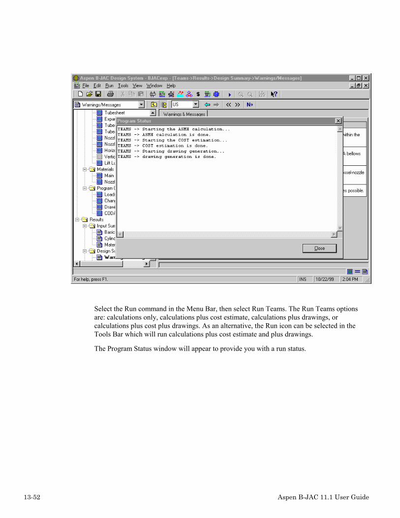
13-52 Aspen B-JAC 11.1 User Guide
Select the Run command in the Menu Bar, then select Run Teams. The Run Teams optionsare: calculations only, calculations plus cost estimate, calculations plus drawings, orcalculations plus cost plus drawings. As an alternative, the Run icon can be selected in theTools Bar which will run calculations plus cost estimate and plus drawings.
The Program Status window will appear to provide you with a run status.

Aspen B-JAC 11.1 User Guide 13-53
The warnings and notes will be displayed first. Note that the flanged and flued type expansionjoint selected does not meet the design requirements. The Teams results will first bereviewed then a bellows type expansion joint will be selected as a possible solution.

13-54 Aspen B-JAC 11.1 User Guide
The Teams results are organized in two five major sections:• Design Summary• Vessel Dimensions• Price• Drawings• Code Calculations
The Design Specification sections is shown here.

Aspen B-JAC 11.1 User Guide 13-55
The limiting MAWP components are shown in the above summary. The MAWP for thetubesheets are limited to the specified design conditions. To review the MDMT results, selectthe MDMT tab.

13-56 Aspen B-JAC 11.1 User Guide
Select the Cylinders/Covers/Belts to review the cylinder results summary.

Aspen B-JAC 11.1 User Guide 13-57
Calculation results for the body flanges are shown above.

13-58 Aspen B-JAC 11.1 User Guide
Teams provides results per the TEMA method and per the applicable selected code method.The program will use the thicker of the two methods.

Aspen B-JAC 11.1 User Guide 13-59
The cost estimate is based upon the Teams design code calculation results and themanufacture settings. The manufacturing standards are accessed by selecting Tools from theMenu Bar, selecting Data Maintenance, and then selecting Costing.

13-60 Aspen B-JAC 11.1 User Guide
The scaled outline drawing can be viewed by selecting Setting Plan in the navigator. To viewa specific area of the drawing, window the section of the drawing to be viewed. Select Viewcommand in the Menu Bar and then select Zoom In. As an alternative, use the magnifyingglass icon in the Tools Bar. Use Zoom Out to restore the drawing to full view. The standardsetting plan drawing can be accessed by selecting All Drawings in the navigator.

Aspen B-JAC 11.1 User Guide 13-61
To review the detail calculation documentation, select the component from the CodeCalculation area of the navigator. Shown above is the tubesheet calculations.
Let us now address the warning message concerning the overstress condition of the vesselsupports. Generally if the supports are moved closer to the tubesheets, the shell stresses canbe reduced.

13-62 Aspen B-JAC 11.1 User Guide
Change the flanged and flued expansion joint type to bellow type.

Aspen B-JAC 11.1 User Guide 13-63
Re-run the Teams calculations.

13-64 Aspen B-JAC 11.1 User Guide
Review of the warnings/notes shows that the expansion joint problem has been resolved byusing the bellows type. Other adjustments to the design may done in a similar sequence bymaking changes and re-running Teams.
This completes our mechanical design for the heat exchanger.
❖ ❖ ❖ ❖

Aspen B-JAC 11.1 User Guide 14-1
14 Exporting Results from B-JACto Excel
IntroductionThe Aspen B-JAC Windows user interface is designed to allow you to export input andresults information into an Excel spread sheet.
This chapter describes how to use these export features. Topics include:
• Export features
• Exporting results to an existing spread sheet template
• Creating your own customized template
• Copying and pasting input and results from a B-JAC application to Excel
• Copying and pasting drawings to Excel
• Launching a B-JAC application from Excel
Export features -- B-JAC TemplatesYou can export the program results to an Excel spreadsheet. Several Excel spreadsheettemplates have been provided for your use. You can select one of the pre-formatted outputsummaries such as TeamsSummary.xlt or you can select one of the blank templates such asHetranBlank.xlt and customize your output in Excel.

14-2 Aspen B-JAC 11.1 User Guide
Exporting results to a B-JAC standard summary template or yourcustomized template
File / Export function - spread sheet created without Excel being open:
First open the B-JAC program window and open an exchanger design file, *.BJT. If no resultsare present, run B-JAC to obtain results. Select the “File / Export to” functions from theMenu Bar. Select to open the default template or you can specify which template to open.You can set the default template from the “Tools / Program Settings / Template” window. Ifyou are selecting which template to open, select from the template list, HetranSummary,TeamsSummary, AerotranSummary or your customized template, located in theBJAC10\DAT\Template sub-directory. Select to open the template. Then provide a file nameto save the results as a spread sheet *.xls data file. Results for the B-JAC design file will benow be saved in the created Excel spreadsheet.
Spread sheet created with Excel open
First open the B-JAC program window and open an exchanger design file, *.BJT. If no resultsare present, run B-JAC to obtain results. Open Excel and then open the desired Exceltemplate, HetranSummary, TeamsSummary, AerotranSummary, or your own customizedtemplate, located in the BJAC10\DAT\Template sub-directory. For information on how tocreate your own customized template, see the next section. Enable the macros. Results forthe B-JAC design file will be shown in the Excel spreadsheet. If you wish to save theseresults as *.xls file, use the File / Save function in Excel.
Creating your own customized TemplateTo create you own customized Excel spreadsheet for the results from B-JAC, first make acopy of the *Blank.xlt template located in the BJAC10\DAT\Template sub-directory andrename it to use as your template for the customized results form. Open this new template inExcel. Enable the macros. Now by selecting various sections of the output results in B-JACyou can drag and drop into your template. You can change what information is moved fromB-JAC by clicking on the right hand mouse button and selecting Drag-Drop format. You canselect to drag-drop the value or units of measure only or to drag-drop the Caption, value, andunits. For more information on customizing the spreadsheet in Excel, access Help providedin Excel. Once your customized template is complete and saved, every time B-JAC is run youcan open your customized template to review the results from the run.

Aspen B-JAC 11.1 User Guide 14-3
Copying Data from a B-JAC application to Excel
Copy Format:
First you need to set the format for the copy. By default, the Drag-Drop function copies onlythe value (or values) of information. To reset the format, select Tools/ProgramSettings/Advanced and set the copy format.
• Value only
• Value and units of measure
• Caption, value ands units of measure
• Units of measure only
Copying Individual fields:
Select (or highlight) the information you wish to copy by clicking and holding down the leftmouse button on the value and then dragging the mouse cursor to the desired location in thespread sheet. This ‘drag & drop” method will move the value as was as any caption and unitsyou have set in the format described above.
Copying Columns of information:
Select (or highlight) the column of information you wish to copy by clicking and holdingdown the left mouse button on any value in the column and then dragging the mouse cursor tothe desired location in the spread sheet. This ‘drag & drop” method will move the entirecolumn of information as was as any caption and units that you have set to be copied in theformat settings.
Copying Tables of information:
Select (or highlight) the table you wish to copy. Select the Edit / Copy function in the MenuBar. Select the location for the table in the spread sheet. Select the Edit / Paste function fromthe Menu Bar in Excel to paste the table into the spread sheet. This copy & paste method willmove the entire table of information as was as any caption and units that you have set to becopied in the format settings.
Copying drawings:
Select the drawing you wish to copy by clicking and holding down the left mouse button onthe drawing then dragging the mouse cursor to the desired location in the spread sheet. This‘drag & drop” method will move the drawing with border into the spread sheet.

14-4 Aspen B-JAC 11.1 User Guide
Example of Pasting Aspen B-JAC results into Excel.This example shows the steps necessary to paste a column of information from the IntervalAnalysis Performance in the Aspen Hetran results into an Excel spreadsheet.
• Open the B-JAC program window and select a Hetran file. If results are not present, runthe file.
• Open Excel and open the HetranBlank.xlt template. Save as a different template name.
• Locate the Overall Coefficient column in the Interval Analysis / Performance section ofHetran.
• Set the format for the copy to caption, values, and units under Tools/Programsettings/Advanced as described above in the Copy Format instructions.
• Using the mouse click on the Overall coefficient column with the left mouse button anhold the button down. Now drag the mouse cursor to the desired location in your Excelspread sheet and release the mouse button.

Aspen B-JAC 11.1 User Guide 14-5
Launching B-JAC programs from ExcelOnce you have created you own Excel spread sheet, it is possible to launch the B-JACprograms from within the spread sheet. To run a B-JAC program from within Excel, selectAspen B-JAC / Run from the Excel menu bar. Input design parameters may be changedwithin Excel and the results in the B-JAC program and in the spread sheet will reflect thesechanges.
❖ ❖ ❖ ❖

14-6 Aspen B-JAC 11.1 User Guide

Aspen B-JAC 11.1 User Guide 15-1
15 Using the ASPEN B-JACActiveX Automation Server
IntroductionThis chapter describes how to use the ASPEN B-JAC ActiveX Automation Server. The topicsinclude:
• About the Automation Server
• Viewing the ASPEN B-JAC objects.
• Overview of the ASPEN B-JAC objects
• Programming with the ASPEN B-JAC objects
• Reference information
This chapter assumes that you are familiar with Microsoft Visual Basic and understand theconcepts of object-orientated programming.
The examples in this chapter use Visual Basic 5.0 and Visual Basic for Application (VBA) asthe Automation Client. Much of the code examples in this chapter are taken from the examplefiles, which are distributed with the standard ASPEN B-JAC installation. If you installedASPEN B-JAC in the default location, the code examples are located in the ProgramFiles\AspenTech\BJAC101\xmp\VB.
The examples use the example problem file LiquidLiquid.BJT, which is provided with thestandard ASPEN B-JAC installation. You will find this file in ProgramFiles\AspenTech\BJAC101\xmp if you installed ASPEN B-JAC in the default location.

15-2 Aspen B-JAC 11.1 User Guide
About the Automation ServerThe ASPEN B-JAC Windows user interface is an ActiveX Automation Server. The ActiveXtechnology (formally called OLE Automation) enables an external Windows application tointeract with ASPEN B-JAC through a programming interface using a language suchMicrosoft’s Visual Basic. The server exposes objects through the Common Object Model(COM).
With the Automation Server, you can:
• connect both the inputs and the results of the ASPEN B-JAC program to otherapplications such as design programs of databases.
• write your own user interface to control the ASPEN B-JAC program from creating a newapplication to printing results of the calculation. With your own interfaces you can use theASPEN B-JAC program as a model for your design plan or use the ASPEN B-JACprogram as a part of your design system.
Using the Automation ServerIn order to use the ASPEN B-JAC Automation Server, you must:
• Have ASPEN B-JAC installed on your PC.
• Be licensed to use ASPEN B-JAC.
The ASPEN B-JAC Automation Server consists of its principal componentBJACWIN.EXE, the core component AtvCoreComponents.DLL and other supportingcomponents.
The principal component, BJACWIN.EXE, is an out-of-process component, orActiveX EXE. You will use this component to deal with ASPEN B-JAC documentsand applications such as Hetran. The core component, ATVDataServer.DLL, is an in-process component, or ActiveX DLL. You will use this component to accessapplication objects and data objects. The supporting components consist of severalDLLs and OCXs and are intended to be for internal use only. If you installed theprogram in the default location, you will find those files in the ProgramFile\AspenTech\BJAC101\xeq.
If you access ASPEN B-JAC objects using strongly typed declaration, you mustreference the ASPEN B-JAC Automation Server in your project before you access theobjects in your program.

Aspen B-JAC 11.1 User Guide 15-3
To reference the ASPEN B-JAC Automation Server from Visual Basic, or Excel, openthe References dialog box, and check the ASPEN B-JAC Design System box andATV core component box as shown here:
If ASPEN B-JAC Design System or ATV core component does not exist in the list,click Browse and find the ASPEN B-JAC executable directory. SelectBJACWIN.EXE or ATVDataServer.DLL.
If you opened a project used earlier version of the ASPEN B-JAC or the Excelexample file for the ASPEN Hetran, HETRANAUTO.XLS, you might find missingcomponents in your project. In order to use the ASPEN B-JAC objects you shouldopen the Reference dialog box and check the ASPEN B-JAC Design System box orthe ATV core component box as mentioned earlier.
Error HandlingErrors may occur in calling methods or accessing properties of the ASPEN B-JAC objects. Itis important to create an error handler for all code, which accesses an automation interface.An automation interface may return a dispatch error for many reasons, most of which do notindicate fatal or even serious errors.
Although any error will normally causes a dialog box to be displayed on the user’s screen, itis strongly recommended that you write your own error handler to trap the error in order toexit the application cleanly or proceed with the next step.

15-4 Aspen B-JAC 11.1 User Guide
Releasing ObjectsOne object can not be destroyed unless all of the references to the object are released.Therefore, it is a good practice that you always release the objects you have referenced whenthe objects are no longer needed. Releasing an object is a simple task. This can be done bysetting the object to Nothing.
As a general rule, you should release the objects in the opposite sequence as the objects arereferenced. For example:Dim objBjac As ObjectDim objApp As Object‘ References objectsSet objBjac = CreateObject(“BJACWIN.BJACApp”)Set objApp = objBjac.LoadApp(“Hetran”). . .‘ Release objectsSet objApp = NothingSet objBjac = Nothing
Viewing the ASPEN B-JAC ObjectsThe detailed description of the ASPEN B-JAC objects, including properties, methods andnamed constants, may be viewed in the Automation Client Object Browser.
To use the browser, in Visual Basic and Excel, from the View menu, click Object Browser,the Object Browser will be displayed as shown here:

Aspen B-JAC 11.1 User Guide 15-5
Overview of the ASPEN B-JAC ObjectsThe object exposed by ASPEN B-JAC Automation Server is the BJACApp object. Throughthis object other objects and their properties and methods may be accessed.
Object Model Diagram
The following diagram provides a graphical overview of the ASPEN B-JAC object model:
The BJACApp Object
The BJACApp object is the principal object exposed by ASPEN B-JAC. This object providesmethods and properties such as:
• Creating a new or opening an existing ASPEN B-JAC file
• Creating a new or getting an existing ATVApp object
• Controlling the default settings of the ASPEN B-JAC Window
• Enumerating ATVApp objects
BJACApp ( The ASPEN B-JAC client object)
ATVApps ( Application object collection )
ATVApp ( Application object )
ATVArrays ( Array data objects collection )
ATVArray ( Array data object )
ATVScalars ( Scalar data objects collection )
ATVScalar ( Scalar data object )
Exposed by BJACWIN.EXE
Exposed by AtvDataServer.DLL

15-6 Aspen B-JAC 11.1 User Guide
• Printing results
• Saving a file
For more information about the BJACApp object refer to the “Reference Information”section.
Example of Opening an Existing File
The following Visual Basic example creates the ASPEN B-JAC object for an existing ASPENB-JAC document, and shows the ASPEN B-JAC Window by setting the Visible property toTrue.Function OpenFile(ByVal FileName As String) As BJACApp
Dim objBjac As BJACApp ' Declare the BJAC objectSet OpenFile = NothingOn Error GoTo ErrorHandler ' Error trapSet objBjac = New BJACApp ' Create the BJAC objectIf Not objBjac.FileOpen(FileName) ThenMsgBox "Can't open file " & FileNameExit FunctionEnd IfobjBjac.Visible = True ' Show BJAC WindowSet OpenFile = objBjacSet objBjac = NothingExit Function
ErrorHandler:MsgBox "Can't create BJAC object"End ' End the program
End Function
The above code uses Set objBjac = New BJACApp to create an ASPEN B-JAC object. Youcan use Set objBjac = CreateObject(“BJACWIN.BJACApp”) to get the same result.
Note If there is a running ASPEN B-JAC Automation Server on your PC, the effect of usingSet objBjac = New BJACApp or Set objBjac =CreateObject(“BJACWIN.BJACApp”)only gets a reference to the same instance of the server.

Aspen B-JAC 11.1 User Guide 15-7
The ATVApp object
The ATVApp object exposes the ASPEN B-JAC application, such as Hetran. Throughproperties and methods of the ATVApp object you can:
• Change the units of measure set
• Execute the calculation engine
• Check application status
• Enumerate inputs and results through data objects collections
Of the many properties and methods in the ATVApp object, there are four collections forrepresenting data:
• Scalars – a collection of ATVScalar objects for representing scalar variables of input
• Arrays – a collection of ATVArray objects for representing array variables of input
• ResultScalars – a collection of ATVScalar objects for representing scalar variables ofresults
• ResutlArrays – a collection of ATVArray objects for representing array variables ofresults
Those data collections provide a bridge to allow you to manipulate data in the applicationincluding changing the units of measure, modifying the value and so on.
For more information about the ATVApp object refer to the “Reference Information”section.
Example of using an ATVApp object
The following Visual Basic example shows how to get the ASPEN B-JAC Hetran object fromthe BJACApp object by opening an existing file, checking the input status and launching thecalculation engine.Sub AccessHetran()Dim objBjac As BJACApp ' Declare a BJAC objectDim objHetran As ATVApp ' Declare a ATVApp objectDim nRetCode As IntegerOn Error Resume Next ' Error trap
' We try to get a BJACApp objectSet objBjac = New BJACAppIf Err.Number <> 0 ThenMsgBox "Can't create BJACApp object!"End
End If

15-8 Aspen B-JAC 11.1 User Guide
' First, we check to see if Hetran object is alreay there' in case there is a BJACApp object running and' Hetran object is created.If objBjac.Hetran Is Nothing Then
' If no Hetran object in the current BJACApp object' then we open the sample file to get a Hetran object
If Not objBjac.FileOpen( _"C:\Program
Files\AspenTech\BJAC10\xmp\LiquidLiquid.BJT") ThenMsgBox "Can't open the file."GoTo ExitThisSub
End IfEnd If
' Get the reference to HeatranSet objHetran = objBjac.GetApp("Hetran")
' Notice that this time we use method GetApp' to get Hetran object. You can use' Set objHetran = objBjac.Hetran' or' Set objHetran = objBjac.ATVApps("Hetran")
' Check to see if Hetran object is loaded' this time.If objHetran Is Nothing ThenMsgBox "Hetran is not created."GoTo ExitThisSub
End If
' We change the units of measure to SIobjHetran.UomSet = ATV_UOMSET_SI
' Check to see if you can run HetranIf objHetran.CanRun() Then
' If yes, run Hetran and get the return codenRetCode = objHetran.Run()
' if we got any errorIf nRetCode <> 0 ThenMsgBox "Error in Hetran calculation. Code=" & nRetCode
End IfEnd If
' Release objectsExitThisSub:Set objHetran = NothingSet objBjac = Nothing
End Sub

Aspen B-JAC 11.1 User Guide 15-9
ATVScalar Object and ATVArray Object
The ATVScalar object and the ATVArray object are used to represent data in the ASPEN B-JAC objects. As mentioned earlier, the ATVScalar object is used for scalar data and theATVArray is used for array data. The ATVApp uses two pairs of collections containingATVScalar objets and ATVArray objects to represent inputs and results, respectively. Byaccessing the properties and methods of the data objects, you can:• Return or set a value• Change the units of measure if the data is a physical quantity• Check the status of the variable
For more information about programming with the ATVScalar object and ATVArrayobject is provided in the “Programming with the ASPEN B-JAC Objects” section. Detailedreference information about the ATVScalar object and ATVArray object is provided in the"Reference Information” section.
Example of accessing data objects
The following Visual Basic example shows how to access a scalar input variable, change itsunits of measure and value, and how to retrieve an array data from results. Note that theexample code is stored in the prjAccessData.VBP VB project in the xmp\VB subdirectory.
Sub Main()' Variale declarationsDim objBjac As BJACAppDim objHetran As ATVAppDim objScalar As ATVScalarDim objArray As ATVArray
' We try to get a BJACApp objectSet objBjac = New BJACApp
' We use FileClose to make sure there is no ATVApp object' loaded since we are going to open the existing sample fileobjBjac.FileClose
' Open a BJAC document file to create a Hetran objectobjBjac.FileOpen
' Get the Hetran object referenceSet objHetran = objBjac.HetranIf objHetran Is Nothing ThenMsgBox "Cann't create Hetran object." & vbCrLf & _
"Please try a different file."End
End

15-10 Aspen B-JAC 11.1 User Guide
' Get the data object for hot side flow rate' Notice that "FlRaHS" is the variable name for' hot side flow rate in Hetran object.Set objScalar = objHetran.Scalars("FlRaHS")
' We declare a buffer to retrieve current value' in units "kg/s" no matter what units are actually' used in the dataDim xBuf As SinglexBuf = objScalar.Value("kg/s") ' now xBuf is in kg/s
' Let's increase the flow rate by 0.5 kg/sobjScalar.Value("kg/s") = xBuf + 0.5
' Let's try to access Tube OD data objectWith objHetran.Scalars("TubeOD").Uom = "in" ' Change the units string to "in".Value = 0.75 ' Now the tube OD has value of 0.75 in
End With
' Run the Hetran appliationIf objHetran.CanRun Then objHetran.Run
' For example, let's retrieve the shell side pressure dropshown in the' optimization path.' Notice that because variable arPresDropShell is an array' you will need to access the array collection.Set objArray = objHetran.ResultArrays("arPresDropShell")
' Loop through the array to view every element in the arrayDim I As IntegerFor I = 1 To objArray.GetSize()Debug.Print objArray.Values(I)
Next I
' release objectsSet objScalar = NothingSet objArray = NothingSet objHetran = NothingSet objBjac = Nothing
End Sub

Aspen B-JAC 11.1 User Guide 15-11
Programming with ASPEN B-JAC ObjectsIn this section we will discuss the programming with the APSEN B-JAC object in depth. Thetopics include:
• Creating application and file operations
• Enumerating objects
• Checking status
• Controlling the units of measure
• Accessing data
• Exploring variables
• Limitations and restrictions
Creating Application and File Operations
To create or get a BJACApp object, you can either useSet objBJAC = new BJACApp
orSet objBJAC = CreateObject(“BJACWIN.BJACApp”)
Once you have a connection to the BJACApp object, the next step is to create a new file oropen an existing file.
The BJACApp object exposes several methods allowing you to deal with the ASPEN B-JACdocument file including creating a new file, opening an existing file, printing a file or saving afile.
Using FileNew
One way to create an ASPEN B-JAC application is to use the FileNew method in theBJACApp object. The code segment below describes how to create a new file for the ASPENTeams:
Dim objBjac As ObjectDim objTeams As ObjectSet objBjac = CreateObject("BJACWIN.BJACApp")objBjac.FileNew "Teams"
By executing above code a new Teams application is created. The document containing thenew application is named as UNTITLE.BJT. Notice that the actual document is not created onthe disk until the FileSave or FileSaveAs method is called.

15-12 Aspen B-JAC 11.1 User Guide
The FileNew method takes the argument AppName as optional. If you just call the methodusing the default, in which the argument AppName is an empty string, then you will see theFile New dialog box will appear:
You can check the box next the application to create one or more applications.
Note Because the BJACApp object can only contain one document at a time, the FileNewmethod will unload the current document before creating a new one. In other words, you cannot call the FileNew twice to create two different applications in the same BJACApp object.
Using LoadApp
The BJACApp object can contain one or more applications. If you want to add a newapplication to your existing document, use the LoadApp method. For example if you want toadd a Hetran application in the above example code, you use
Dim objHetran as ATVAppSet objHetran = objBjac.LoadApp(“Hetran”)
By executing the above code, a Hetran application object will be added to the document.
Using FileOpen
The Method FileOpen, in the BJACApp object, is the only way you can open an existingASPEN B-JAC document file. The method uses one string argument to represent the name ofthe document file to be opened. The argument is optional. If the default is used or an emptystring is assigned, a standard Windows File Open dialog box will appear, in which the usercan browse the system to select a demand file.
Note The FileOpen method also unloads the current document before loading thedocument supplied. You should save the document if you have made changes to thedocument before calling the FileOpen method.

Aspen B-JAC 11.1 User Guide 15-13
Using FilePrint
Once the calculation is executed successfully, the results will be generated. And then you canuse the FilePrint method to print the results in the format created by the ASPEN B-JACprogram. The following code segment shows how to use the FilePrint method to print theTeams results after the calculation succeeded:
If objTeams.Run() = 0 ThenobjBjac.FilePrint
End If
By default the FilePrint method will print every result form for every application in theobject. If you want to just print one application, you can supply the application name in thefirst argument. For example, to print Teams only:
objBjac.FilePrint “Teams”
Or if you only want to print a portion of the results, you can set the second argument to False.For example:
objBjac.FilePrint , False
In this case, the ASPEN B-JAC Print Dialog box will appear as shown here:
This dialog box is the same as you select the Print menu in the ASPEN B-JAC user interface.You can select any result by checking box next the list item and change other settings as well.

15-14 Aspen B-JAC 11.1 User Guide
Using FileSave and FileSaveAs
As mentioned earlier if you use FileNew to create a new file the actual file is not created inthe disk until the file is saved. To save an ASPEN B-JAC document file to the disk you usethe FileSave or FileSaveAs method.
Use the FileSaveAs method or to save a copy of an existing document under a different nameor an existing document to a different drive or path. For example, supply an existingfilename, path to save, and name a new document:
objBjac.SaveAs “C:\Program File\MyBJACFile\Exchan ger.BJT”
Use the FileSave method to save the document in the same filename, or in the default namedefined by the program. For example:
objBjac.Save
It is strongly recommended that you use the FileSaveAs method to save the document in adesire filename if the document was newly created using the FileNew method. Because thedefault filename defined by the program is UNTITLE.BJT.
The argument of the FileSaveAs method can be omitted. If do so, a standard “Save As”Windows dialog box will appear and you will be able to specify any filename or file path.
Enumerating Objects
The ASPEN B-JAC Automation Server provides following collections to keep track of theobjects:
• Application collection: BJACApp.ATVApps
• Scalar data collection for input: ATVApp.Scalars
• Array data collection for input: ATVApp.Arrays
• Scalar data collection for results: ATVApp.ResultScalars
• Array data collection for results: ATVApp.ResultArrays
You can use For Each …Next to enumerate the objects in the collections, without losing anypart of the information for the BJACApp object. This is particularly important if you want togenerate your own database to store input and results information rather than using theASPEN B-JAC document, or create your own graphic user interface to access the ASPEN B-JAC objects.

Aspen B-JAC 11.1 User Guide 15-15
The following example code prints names and values for all scalar variables in the input:Dim objApp as ATVAppDim objScalar as ATVScalar…For Each objScalar In objApp.Scalars
Debug.Print objScalar.Name, objScalar.ValueNext
Checking Status
Checking Status for an application or for a data object is important when you want to knowwhether you have made changes to the application, whether you can run the program, orwhether the results are present.
Using IsSaved
The IsSaved property is provided in the BJACApp object and the ATVApp object. You canuse this property to check to see if any change in the input of the document has been madeand the changes have not been saved. This is particularly useful when changes have beenmade and you need to save these changes.
The following code gives an example that shows how to use the property:Private Sub SaveFile(ByVal objBjac as BJACApp )
If Not objBjac.IsSaved ThenobjBjac.FileSave
End IfEnd Sub
If you just want to check to see if a particular application has been modified or not, you canquery the ATVApp.IsSaved property. For example:
Dim objHetran as ATVApp…If Not objHetran.IsSaved Then
objBjac.FileSaveEnd If
Notice that once the document is saved the IsSaved property will return a value of True toreflect the change of the status.
Using IsComplete
The IsComplete property is used to check the completion status for an application or checkfor required input data. The ASPEN B-JAC object provides a variety of comprehensivealgorithms checking the completion status for applications based on various input conditions.The IsComplete property returns a value of True to indicate the status is complete.

15-16 Aspen B-JAC 11.1 User Guide
Use the IsComplete property in an ATVApp object to check the completion status for theapplication. For example:
Dim objHetran as ATVApp…If objHetran.IsComplete then
‘ the input is complete,…End if
Use the IsComplete property in a data object to check to see if the input data is complete. Foran input data, if the data is not required then the property always returns True. If the data isrequired and the value is missing then the IsComplete property returns False.
The following example shows how to find an incomplete data in the input scalar objects:
Function FindIncompleteData(ByVal objApp As ATVApp) As ATVScalarDim objScalar As ATVScalar
' Loops through the scalar objectsFor Each objScalar In objApp.Scalars
' Checks to see if the data is completeIf Not objScalar.IsComplete Then
' Found the first incomplete data, return the data and exitSet FindIncompleteData = objScalarExit Function
End IfNext
End Function
Controlling the Units of Measure
The ASPEN B-JAC user interface has provided a solution to handle the complexity ofdifferent units of measure. Through the ASPEN B-JAC user interface, you can add your ownunits, or change any existing units in the units table, and then use these new or modified unitsfor input field, calculation or printed results without even closing the application window.
The ASPEN B-JAC Automation Server provides you three different levels to control the unitsof measure in your program:
• The UomSet property in the BACApp object
• The UomSet property in the ATVApp object
• The Uom property in the data objects

Aspen B-JAC 11.1 User Guide 15-17
UomSet in BJACApp Object
Use the UomSet property in the BJACApp object to view or change the units of measure setfor the BJACApp object. For example:
Dim objBjac as BJACAppDim nSet as Integer…
‘ Gets the current units setnSet = objBjac.UomSet
‘ Checks to see if it’s SI, if not then change it to SIif nSet <> ATV_UOMSET_SI then objBjac.UomSet = ATV_UOMSET_SI
Note: The UomSet property is the default units set for application objects. Changing UomSetin the BJACApp object will not have any effect on the applications that are already created.
UomSet in ATVApp Object
Use the UomSet property in an ATVApp object to return or change the units of measure setfor the application. For example:
Dim objApp as ATVApp. . .
‘ Sets the units set to user defined SET1objApp.UomSet = ATV_UOMSET_SET1
Note: By changing the UomSet in the ATVApp object, the units of physical quantity dataobjects in the application will be changed to the units defined in the units set table.Consequently the values of these data will be converted appropriately to the new units if thecurrent units set is different. Also, you will notice that the units controls in the ASPEN B-JACuser interface will prompt in accordance with the changes.
Uom in ATVScalar Object and ATVArray Object
Use the Uom property in the ATVScalar and ATVArray objects to view or change the unitsof measure for the data. For example:
Dim objHetan as ATVApp…
‘ Changes the units of hot side flowrate to “lb/s”objHetran.Scalars(“FlRaHS”).Uom = “lb/s”
Notes:
• The Uom property only applies to the physical quantity data, for example, temperatureand pressure.
• The Uom property is a string. You must assign an existing unit string to the data. The unitstring remains unchanged if an invalid unit string is supplied.
• Changing the unit string will not result in the value being converted.

15-18 Aspen B-JAC 11.1 User Guide
Accessing Data
The data in the ASPEN B-JAC applications can be accessed through the two data objects:ATVScalar and the ATVArray. You can not create a new data object, but you can access allthe attributes including changing the value or unit string for all the data objects. To access adata of interest, one possible method is as follows:
• Locate the variable of interest.
• Find out the attributes for the variable. Especially, you need to know the variable is ascalar or an array, and input or result.
• Get the reference to the data object using the appropriate data object collection.
• View or change the value or unit string if necessary.
Detailed information about the data objects is given in the “Reference Information” section.
Exploring Variables
In order to access the data of interest in an ASPEN B-JAC design, you need to locate thevariables of interest in the system. To do this, you can use the Application Browser togetherwith the Variable List Window in the ASPEN B-JAC User Interface to navigate the data.
In the ASPEN B-JAC user interface, every application, for example, Hetran, is represented inan Application Browser. The Application Browser has a tree structure and contains the visualrepresentation for inputs and results in a series of forms. On each form, for input and results,each data control is connected a data object, and each data has a variable associated with it.The Variable List window will list all the variables behind the form.
To open the Variable List Window, from the View menu, click Variable List.

Aspen B-JAC 11.1 User Guide 15-19
The Variable List Window displays the attributes including names, variable type, currentvalues, and descriptions for all the variables used on the form.
Notice that the indicates an input variable, and the indicate a result variable.
Another way to locate a variable is to view the variable attributes in the description pane onthe Application Browser by clicking a control.
To show the variable attributes on the description pane:
• From the Tool menu, click the Program Setting to display the program setting dialog box.
• Click the Advanced tab, and check the option Show Variable Attributes on theDescription Pane. Click OK to close the dialog box.
• On the Application Browser, display any input or results form.
• Click a control on the form to see the attributes of the variable associated with the control,which are isplayed on the description pane.
For example:
The attributes associated with the data controlare displayed here.
Click data control here

15-20 Aspen B-JAC 11.1 User Guide
Limitations and Restrictions
The ASPEN B-JAC Automation Server is a single threaded object and only one copy of itsinstance can be created at a time. In other words, if the server is running before you create aBJACApp object, using following code:
Set objBJAC = New BJACWIN.BJACApp
or Set objBJAC = CreateObject(“BJACWIN.BJACApp”)
will share with the existing thread.
The BJACApp object can only deal with one document at a time. If you try to create anothernew document or open another existing document, the consequence is that the program willunload the current document first.
Although multiple ATVApp objects can co-exist in the BJACApp object, you can only createone kind of the application object at a time. For example, the Hetran object, is not allowedhaving more than one copy. In other words, you can not create two Hetran applications in thesame BJACApp object.
Only the BJACApp object can be created in your code. Other objects can only be referenced.The object collections can only be referenced. You can not add any item to the collections. Ifyou try to do so, it may cause unpredictable results.

Aspen B-JAC 11.1 User Guide 15-21
Reference InformationThe topics in this section includes:
• Lists of the members for each exposed ASPEN B-JAC classes
• Member descriptions
• Error descriptions
Members of Class BJACAppName Member Type Data Type Description
Aerotran Function Object Returns the ATVApp object for AerotranATVApps Property (Set) Collection Returns the ATVApp objects collectionExecutionControlEnabled Property (Get/Let) Boolean Returns/sets a value that determines
execution controlFileClose Sub Closes the current documentFileExit Sub Terminates the programFileNew Function Boolean Creates a new documentFileOpen Function Boolean Opens an existing documentFilePrint Sub Prints the resultsFileSave Function Boolean Saves the documentFileSaveAs Function Boolean Saves the document to a different fileGetApp Function Object Returns an ATVApp objectGetFileName Function String Returns the current document filenameGetFilePath Function String Returns path nameGetList Function Long Retrieves static list informationGetListCollection Function Long Retrieves static list informationGetUomString Function String Returns a valid units stringGetVersion Function String Returns the version informationHetran Function Object Returns the ATVApp object for HetranHide Sub Hides the UI WindowsIsSaved Property (Get) Boolean Returns a Boolean value determining
whether the document is savedLanguage Property (Get/Let) Long Returns/sets the language for the UI
WindowsLoadApp Function Object Creates or gets an ATVApp objectMinimize Sub Minimize the UI WindowsShow Sub Show the UI WindowsTeams Function Object Returns the ATVApp object for TeamsUomSet Property (Get/Let) Long Returns/sets the default units of measure
setVisible Property (Get/Let) Boolean Returns/sets a value that controls the
visibilty of the UI Windows

15-22 Aspen B-JAC 11.1 User Guide
Members of Class ATVAppName Member Type Data Type DescriptionArrays Property (Get) Collection Returns the collection of array data
objects for inputCanRun Property (Get) Boolean Returns a value determining whether the
calculation can be executedDisplayDrawing Sub Displays the given drawingExportToDXF Function Boolean Exports drawings to AutoCAD DXF format
file and returns True if successfulHasResults Property (Get) Boolean Returns a value indicating whether the
results are presentIsComplete Property (Get) Boolean Returns a value indicating whether the
required data are inputtedName Property (Get) String Returns the name of the objectParent Property (Get) Object Returns the parent objectResultArrays Property (Get) Collection Returns the collection of array data
objects for resultsResultScalars Property (Get) Collection Returns the collection of scalar data
objects for resultsRun Function Long Runs the calculation engine and returns
the statusRun2 Function Long Runs the calculation engine with the given
run type, and returns the statusRunFinished Event Gets fired when the calculation is doneScalar Property (Get) Collection Returns the collection of scalar data
objects for inputUomSet Property (Get/Let) Collection Returns or sets the units of measure set
for the application

Aspen B-JAC 11.1 User Guide 15-23
Members of Class ATVScalarName Member Type Data Type DescriptionCategory Property (Get) Long Returns a value that indicates the data
categoryIsComplete Property (Get) Boolean Returns a value that indicates whether the
required data is inputtedIsEmpty Function Boolean Check to see if the data is emptyName Property (Get) String Returns the name of the data objectParent Function (Get) Object Returns the parent objectPQOrListType Property (Get) String Returns the physical quantity name if the
data is a physical quantity, or the name ofthe list if the data is a static list.
Text Property (Get) String Returns a supplemental informationUom Property (Get/Let) String Returns a string that represents the unit
for a physical quantity data.Value Property (Get/Let) Variant Returns/sets a value for the data
Members of Class ATVArrayName Member Type Data Type DescriptionCategory Property (Get) Long Returns a value that indicates the data
categoryInsert Sub Insets an element in the arrayIsComplete Property (Get) Boolean Returns a value that indicates whether the
required data are inputtedIsElementEmpty Function Boolean Check to see if the given element is emptyIsEmpty Function Boolean Check to see if the whole array is emptyName Property (Get) String Returns the nameParent Property (Get) Object Returns the parent objectPQOrListType Property (Get) String Returns the physical quantity name if the
data is a physical quantity, or the name ofthe list if the data is a static list.
Remove Sub Removes an element from the arrayText Property (Get) String Returns a supplemental informationUom Property (Get/Let) String Returns a string that represents the unit
for a physical quantity data.Values Property (Get/Let) Variant Returns/sets a value for the given element

15-24 Aspen B-JAC 11.1 User Guide
Member Descriptions
Aerotran Method
Gets a reference to an ATVApp object that represents the Aerotran application.
Applies To BJACApp Object
Syntax object.Aerotran
Data Type Object
Remarks: This method is the same as the statement:
Set objAerotran = object.GetApp(“Aerotran”).
Arrays Property (Read-only)
Gets a reference to the collection containing array data objects for input in anATVApp object.
Applies To ATVApp Object
Syntax object.Arrays
Data Type Collection
ATVApps Property (Read-only)
Gets a reference to the collection containing the ATVApp objects in the BJACApp object.
Applies To BJACApp Object
Syntax object.ATVApps
Data Type Collection
Remarks: In the ASPEN B-JAC object, an application object named“UTILITIES” is always loaded for the internal service purpose. This internalapplication object has no visual representation and will stay the BJACApp object aslong as a document is loaded.

Aspen B-JAC 11.1 User Guide 15-25
CanRun Property (Read-only)
Returns a Boolean value that determines whether or not the calculation engine can beexecuted.
Applies To ATVApp Object
Syntax object.CanRun
Data Type Boolean
Remarks If the property ExecutionControlEnabled in the BJACApp object isTrue, the CanRun method will be controlled by the completion of the input. In thiscase, if the IsComplete method in the application object returns True, then the CanRunalso is True. However, if the BJACApp.ExecutionControlEnabled is False, theCanRum always returns True.
Category Property (Read-only)
Returns a long integer that determines the category for the data object.
Applies To ATVScalar Object, ATVArray Object
Syntax object.Category
Data Type Long
Remarks The ASPEN B-JAC object has defined following seven constants for the datacategory:
Constant Value
VB DataType
Description
ATV_DATACATEGORY_PQ 0 Single Physical quantities, such as temperature and pressure.
ATV_DATACATEGORY_LIST 1 Long StaticList, such as TEAM Class. A StaticList data has a list ofitems from which the use can select one and the index of theitem selected will be returned as the value of the data.
ATV_DATACATEGORY_NUM 2 Single Numeric numberATV_DATACATEGORY_STR 3 String Character stringATV_DATACATEGORY_BOOL 4 Boolean Boolean dataATV_DATACATEGORY_VOC 5 String Vocabulary (internal use only)ATV_DATACATEGORY_MSG 6 String Message (internal use only)

15-26 Aspen B-JAC 11.1 User Guide
DisplayDrawing Method
Displays the given drawing.
Applies To ATVApp Object
Syntax object.DisplayDrawing (hWndClient, DrawingID)
ParametershWndClient Long Required. A long value representing the handle of client
window, on which the drawing will be displayed.DrawingID Long Required. A long value representing the drawing to be
displayed. See Drawing ID Definitions below for details.Drawing ID DefinitionsID Description Hetran Teams Aerotran Ensea
10 Outline � � �11 Setting plan � � 20 Material specifications � 30 Sectional � 40 Bundle layout �50 Tubesheet layout � � � �60 Shell � 61 Shell A � 62 Shell B � 70 Shell cover � 80 Front head � 90 Rear head �
100 Floating head � 110 Bundle � 120 Baffles � 130 Flat covers � 140 Front tubesheet � 150 Rear tubesheet � 160 Expansion joint � 171 Gaskets A � 172 Gaskets B � 173 Gaskets C � 181 Body flanges A � 182 Body flanges B � 183 Body flanges C � 184 Body flanges D � 185 Body flanges E � 186 Body flanges F � 190 Vertical supports � 191 Bottom front supports � 192 Top front Supports � 193 Bottom rear Supports � 194 Top rear supports � 200 Weld details �

Aspen B-JAC 11.1 User Guide 15-27
Example
The following code shows how to display the Setting Plan drawing on a VB PictureBoxcontrol. To try this example, paste the code into the Declarations section of a form with aPictureBox control, Picture1, and two command bottoms, Command1 and Command2:Dim objBjac As ObjectDim objApp As Object
Private Sub Command1_Click()' Displays a FileOpen dialog box and let' user to select a BJAC document file' Note: the BJAC document must contain Teams' in order to test the drawing
objBjac.FileOpen
' Releases the object firstSet objApp = Nothing
' Gets a Teams referenceIf objApp Is Nothing Then Set objApp = NothingSet objApp = objBjac.GetApp("Teams")
If objApp is Nothing ThenBeepMsgBox "The document doesn't contain Teams." & vbCrLf & _
"Please try a differnet file."Else
' Displays the setting plan' Note: 11 is the drawing ID for setting plan
objApp.DisplayDrawing Picture1.hWnd, 11End If
' Displays the setting plan' Note: 11 is the drawing ID for setting plan
If Not objApp Is Nothing ThenobjApp.DisplayDrawing Picture1.hWnd, 11
End IfEnd Sub
Private Sub Command2_Click()Unload Me
End Sub
Private Sub Form_Load()
' Creates a BJAC objectSet objBjac = CreateObject("BJACWIN.BJACApp")
' Checks the errorIf objBjac Is Nothing Then
BeepMsgBox "Can't create BJAC object"Unload Me
End IfEnd Sub

15-28 Aspen B-JAC 11.1 User Guide
Private Sub Form_Unload(Cancel As Integer)Set objApp = NothingSet objBjac = Nothing
End Sub
Private Sub Picture1_Paint()' Since the drawing doesn't get repainted automatically,' we need to repaint.
If Not objApp Is Nothing Then objApp.DisplayDrawing Picture1.hWnd,11End Sub
ExecutionControlEnabled Property
Returns or sets a Boolean value that determines whether or not the program can take controlof the calculation execution. When set to True, the input must be complete in order to executethe calculation engine. When set to False, the calculation engine can be launched at any time.
Applies To BJACApp Object
Syntax object.ExecutionControlEnabled [ = Boolean ]
Data Type Boolean
ExportToDXF Method
Exports the drawings to AutoCAD DXF format file and returns True if the function succeeds.
Applies To ATVApp Object
Syntax object.ExportToDXF( [DrawingID][,DXFFileName])
Data Type Boolean
ParametersDrawingID Long Optional. A long value representing the drawing
to be exported. If omitted, all the drawings in theobject will be exported. For detailed definitionsfor DrawingID, see the DisplayDrawing method.
DXFFileName String Optional. A string value representing the filenamedrawing to be exported. If omitted, the currentdocument file will be used.Note: If DrawingID is omitted, each drawing willbe saved to a file with corresponding DrawingIDappended to the DXFFileName.

Aspen B-JAC 11.1 User Guide 15-29
FileClose Method
Closes the current open document.
Applies To BJACApp Object
Syntax object.FileClose
Remarks The FileClose method will close all of the application user interface windowsassociated with the open document and destroy all the objects associated with the documentas well.
Note: Prior to calling this method, you should release all the objects you have referenced inthe code except the BJACApp object.
ExampleDim objBjac As ObjectDim obhApp As ObjectDim objDat As Object. . .‘ Gets a reference to the App objectSet objApp = objBjac.ATVApps(“Aerotran”)
‘ Gets a reference to a dataSet objDat = objApp.Arrays(“BJACDBSymbHS”). . .‘ Release the references prior to calling FileCloseSet objApp = NothingSet objDat = Nothing
‘ Call FileClose to destroy the documentobjBjac.Close. . .

15-30 Aspen B-JAC 11.1 User Guide
FileExit Method
Destroys all the objects in the BJACApp object.
Applies To BJACApp Object
Syntax object.FileExit
Remarks The FileExit method will perform following steps:
• Close all of the application user interface windows associated with the open document ifthe necessary.
• If there is no running BJACWIN.EXE prior to the BJAC object is created in your code,the FileExit method will also destroy the ASPEN B-JAC user interface main window.
Note 1) Prior to calling this method, you should release all the objects referenced in yourcode in the opposite sequence of referencing. 2) Instead of calling this method, you couldsimple use Set objBjac = Nothing in your code.
FileNew Method
Creates a document and returns a Boolean value indicating whether or not the processsucceeded.
Applies To BJACApp Object
Syntax object.FileNew( [AppName])
Data Type Boolean
ParametersAppName String Optional. A string value representing the name
of an application to be created. If omitted, theFile New Dialog box appears and user canselect one or more applications to create.

Aspen B-JAC 11.1 User Guide 15-31
FileOpen Method
Opens an existing document from the disk and returns a Boolean value indicating whether ornot the process succeeded.
Applies To BJACApp Object
Syntax object.FileOpen( [Filename])
Data Type Boolean
ParametersFilename String Optional. A string value representing the name
of an existing document file to be opened. Ifomitted, the standard Windows FileOpenDialog box will be displayed to allow user toopen any existing document.
FilePrint Method
Prints the results for the document if results are present.
Applies To BJACApp Object
Syntax object.FilePrint( [AppName], [PrintAll])
ParametersAppName String Optional. A string value representing the name
of an application to be printed. If omitted, everyapplication will be printed.
PrintAll Boolean Optional. A Boolean value that determineswhether or not to print all of the results. IfFalse, then the Print Selection Dialog boxappears and user can select the results to print.
FileSave Method
Saves the current document file to a disk without changing the name and returns a Booleanvalue indicating whether or not the process succeeded.
Applies To BJACApp Object
Syntax object.FileSave
Data Type Boolean

15-32 Aspen B-JAC 11.1 User Guide
FileSaveAs Method
Saves a copy of the document to the disk using a different name or path and returns a Booleanvalue indicating whether or not the process succeeded.
Applies To BJACApp Object
Syntax object.FileSaveAs( [Filename])
Data Type Boolean
ParametersFilename String Optional. A string value representing the full
path name of the document to be saved. Ifomitted, the standard Windows FileSaveAsDialog box appears and user will be able tospecify the name through the dialog.
GetApp Method
Returns a reference to the specified ATVApp object if succeeded or Nothing if failed.
Applies To BJACApp Object
Syntax object.GetApp( Appname )
Data Type Object
ParametersAppname String Required. A string value representing
the name of the application.
GetFileName Method
Returns a string value representing the full path name of the open document.
Applies To BJACApp Object
Syntax object.GetFileName
Data TypeString

Aspen B-JAC 11.1 User Guide 15-33
GetFilePath Method
Returns a string value representing the file path information.
Applies To BJACApp Object
Syntax object.GetFilePath(Type )
Data Type String
ParametersType Long Required. A Long value indicating the type of
information to be retrieved. Accepted values are:0 - The program installation folder name.1 - Executable files folder name2 - Help files folder name5 - Current open document name10 - Full path name for the static list database11 - Full path name for the units of measurementdatabase
GetListCollection Method
Retrieves information from a static list and returns the number of items in the list if succeededor 0 if failed.
Applies To BJACApp Object
Syntax object.GetListCollection(ListName, ListItems, ListIndices )
Data Type Long
ParametersListName String Required. A string value representing the name of
the static list to be retrievedListItems Collectio
nRequired. A collection to be used to store theitems in the list.
ListIndices Collection
Required. A collection to be used to store thecorresponding indices for the list

15-34 Aspen B-JAC 11.1 User Guide
Example
The following code shows how to retrieve the shell type list in the ASPEN B-JAC static listdatabase:Dim objBjac As ObjectDim ListItems As CollectionDim ListInices As CollectionDim nItems As LongDim I as Long. . .
nItems = objBjac.GetListCollection(“ShellType”,ListItems,ListIndices)
For I = 1 to nItmesDebug.Print ListIndices(I),”,” ListItems(I)
Next I. . .
The code will print following results on the debug window:
0, Program1, E – one pass shell2, F - two pass shell with long. baffle3, G - split flow4, H - double split flow5, J - divided flow (nozzles: 1 in, 2 out)6, K – kettle7, X – crossflow8, V - vapor belt9, J - divided flow (nozzles: 2 in, 1 out)
GetSize Method
Returns the number of elements in the array data object.
Applies To ATVArray Object
Syntax object.GetSize
Data Type Long
GetVersion Method
Returns a string value representing the current version information of the program.
Applies To BJACApp Object
Syntax object.GetVersion
Data Type String

Aspen B-JAC 11.1 User Guide 15-35
HasResults Property (Read-only)
Returns a Boolean value that indicates whether or not the results are present.
Applies To ATVApp Object
Syntax object.HasResults
Data Type Boolean
Hetran Method
Gets a reference to an ATVApp object that represents the Hetran application.
Applies To BJACApp Object
Syntax object.Hetran
Data Type Object
Remarks The following statements will have the same results:Set objApp = objBjac.HetranSet objApp = objBjac.GetApp(“Hetran”)Set objApp = objBjac.ATVApps(“Hetran”)
Hide Method
Hides the ASPEN B-JAC user interface.
Applies To BJACApp Object
Syntax object.Hide
Remarks This is the same as if you use the statement: object.Visible = False
Insert Method
Inserts an element into the array data object.
Applies To ATVArray Object
Syntax object.Insert(Data [,Index] )
ParametersData Variant Required. A variant value to be assignedIndex Long Optional. A Long value indicating where the
new element should be inserted after. If omitted,the new element will be added to the last.

15-36 Aspen B-JAC 11.1 User Guide
IsComplete Property (Read-only)
Returns a Boolean value that indicates whether or not the required data are inputted.
Applies To ATVApp Object, ATVArray Object, ATVScalar Object
Syntax object.IsComplete
Data Type Boolean
IsElementEmpty Method
Returns a Boolean value that indicates whether or not an element in the array data is empty.
Applies To ATVArray Object
Syntax object.IsElementEmpty(Index )
Data Type Boolean
ParametersIndex Long Required. A Long value indicating the
element to be checked.
Remarks Use this method to check an individual element in the array. Use the IsEmptymethod to check the entire array.
IsEmpty Method
Returns a Boolean value that indicates whether or not the data is empty.
Applies To ATVArray, ATVSalar Object
Syntax object.IsEmpty
Data Type Boolean
Remarks Use this method to check to see if the data is empty or not. For ATVArrayobjects, the return is True only if all of the elements in the array are empty.
IsSaved Property (Read-only)
Returns a Boolean value that indicates whether or not the new changes made to the input ofthe open document have been saved.
Applies To BJACApp, ATVApp Object
Syntax object.IsSaved
Data Type Boolean

Aspen B-JAC 11.1 User Guide 15-37
Language Property
Returns or sets a Long value that determines the language used in the program.
Applies To BJACApp Object
Syntax object.Language [ = Setting% ]
Data Type Long
Remarks Currently, the APSEN B-JAC program has assigned followingconstants for language:
Constant Value Description
ATV_LANGUAGE_ENGLISH 1 English ATV_LANGUAGE_GERMAN 2 German ATV_LANGUAGE_SPANISH 3 Spanish ATV_LANGUAGE_FRENCH 4 French ATV_LANGUAGE_ITALIAN 5 Italian ATV_LANGUAGE_CHINESE 6 Chinese ATV_LANGUAGE_JAPANESE 7 Japanese

15-38 Aspen B-JAC 11.1 User Guide
LoadApp Method
Gets or creates an ATVApp object the specified application. It returns the reference to theobject if the method succeeded or Nothing if failed.
Applies To BJACApp Object
Syntax object.LoadApp( Appname )
Data Type Object
ParametersAppname String Required. A string value representing the name
of the application.
Remarks The LoadApp method will create the object if the specified ATVAppobject is available in the BJACApp object. If the object already exists, the method willact like the GetApp method.
Minimize Method
Minimize the ASPEN B-JAC user interface Windows
Applies To BJACApp Object
Syntax object.Minimize
Name Property (Read-only)
Returns a string value representing the name of the object.
Applies To ATVApp Object, ATVArray Object, ATVScalar Object
Syntax object.Name
Data Type String
Remarks When used for an ATVApp object, it returns the name for the application, forexample, Hetran. When used for an ATVArray object or ATVScalar object it returns thevariable name associated with data.

Aspen B-JAC 11.1 User Guide 15-39
Parent Property (Read-only)
Returns a reference to the parent object.
Applies To ATVApp Object, ATVArray Object, ATVScalar Object
Syntax object.Parent
Data Type Object
Remarks It returns a BJACApp object the ATVApp object, and returns an ATVAppobject for the data objects.
PQOrListType Property (Read-only)
Returns a string value that represents the name of the physical quantity or static list assignedto the data.
Applies To ATVScalar Object, ATVArray Object
Syntax object.PQOrListType
Data Type String
Remarks The PQOrListType property is used only for data that are physical quantitiesor lists. The property returns the name of the physical quantity or the list.
Example
The following example shows how to access the PQOrListType property:
Dim objHetran As ATVApp. . .‘ For a PQ dataDebug.Print objHetran.Scalars(“FlRaHS”).PQOrListType‘ For a List dataDebug.Print objHetran.Scalars(“ApplTypeHS”).PQOrListType. . .The result of these statements prints following string on the DebugWindow:
MassFlowrateApplicationTypeHS

15-40 Aspen B-JAC 11.1 User Guide
Remove Method
Removes an element from an array data object.
Applies To ATVArray Object
Syntax object.Remove([Index] )
ParametersIndex Long Optional. A Long value indicating the
element to be removed in the array. Ifomitted, the last element will beremoved.
ResultArrays Property (Read-only)
Gets a reference to the collection containing array data objects for results in an ATVAppobject.
Applies To ATVApp Object
Syntax object.ResultArrays
Data Type Collection
ResultScalars Property (Read-only)
Gets a reference to the collection containing scalar data objects for results in an ATVAppobject.
Applies To ATVApp Object
Syntax object.ResultScalars
Data Type Collection
Run Method
Launches the calculation engine to perform the calculation and returns a status. It returns 0 ifthe calculation succeeded and a none-zero error code to indicate an error if the calculationfailed.
Applies To ATVApp Object
Syntax object.Run
Data Type Long
Remarks See the error descriptions for error code.

Aspen B-JAC 11.1 User Guide 15-41
Run2 Method
Launches the calculation engine to perform the calculation and returns a status. It returns 0 ifthe calculation succeeded and a none-zero error code to indicate an error if the calculationfailed.
Applies To ATVApp Object
Syntax object.Run2([RunType] )
Data Type Long
ParametersRunType Long Optional. A Long value indicating the type of
calculation to be performed. If omitted, themethod will act as same as the Run method.Note: Currently only the Teams application hasdifferent run types as shown below:1- Calculations + Cost + Drawings2- Calculations only3- Calculations + Cost4- Calculations + Drawings
RunFinished Event
Gets fired when the calculation finished successfully.
Applies To ATVApp Object
Syntax Private Sub object_RunFinished
ExampleThe following example shows how to implement the RunFinished method to catch the eventwhen the calculation is done.‘ DeclarationsPrivate objBjac as BJACAppPrivate WithEvents objAerotran as ATVApp ‘ you must use WithEvents. . .
Private Sub MyMain( )‘ Create a BJACApp object, and open an Aerotran problem file
. . .‘ Get the Aerotran object, and run Aerotran
Set objAerotran = objBjac.AerotranobjAerotran.Run
End SubPrivate Sub objAerotran_RunFinished()‘ Add your code below. For example, retrieve some results
. . .End Sub

15-42 Aspen B-JAC 11.1 User Guide
Scalars Property (Read-only)
Gets a reference to the collection containing scalar data objects for input in an ATVAppobject.
Applies To ATVApp Object
Syntax object.Scalars
Data Type Collection
Show Method
Shows the ASPEN B-JAC user interface.
Applies To BJACApp Object
Syntax object.Show
Remarks This statement is equivalent to object.Visible = False
Text Property (Read-only)
Returns supplemental information to the Value property of the data object.
Applies To ATVArray Object, ATVScalar Object
Syntax object.Text([Index] ) for ATVArray object
object.Text for ATVScalar object
ParametersIndex Long Optional. A Long value representing the element
number in the array. If omitted, the first elementis assigned.
Data Type String
Remarks The Text property has no effect on the calculation, and is only used to storeextra information to help understanding of the Value property. For example, for a data objectrepresenting a material, the Value property of the data object will be the material numberassigned by the ASPEN B-JAC, and the Text property will contains the description for thematerial.

Aspen B-JAC 11.1 User Guide 15-43
Example
The example below prints the value and its text of an ATVScalar object on the DebugWindow:Private Sub ShowApplicationType( Byval objHetran As ATVApp )
Dim objAppType As ATVScalar
‘ Get a reference to application type in hot sideSet objAppType = objHetran.Scalar(“ApplTypeHS”)
‘ Display the Value and Text in the Debug WindowDebug.Print objAppType.Value, objAppType.Text
End Sub
On the Debug Window, the results are: 1 Liquid, no phase change
Uom Property
Returns or sets a String that represents the unit for a physical quantity data object.
Applies To ATVArrayApp Object, ATVScalar Object
Syntax object.Uom [=NewUnitString] )
Data Type String
Remarks If an invalid unit string is supplied, the unit string remains unchanged.Changing the unit string will not cause the value conversion.
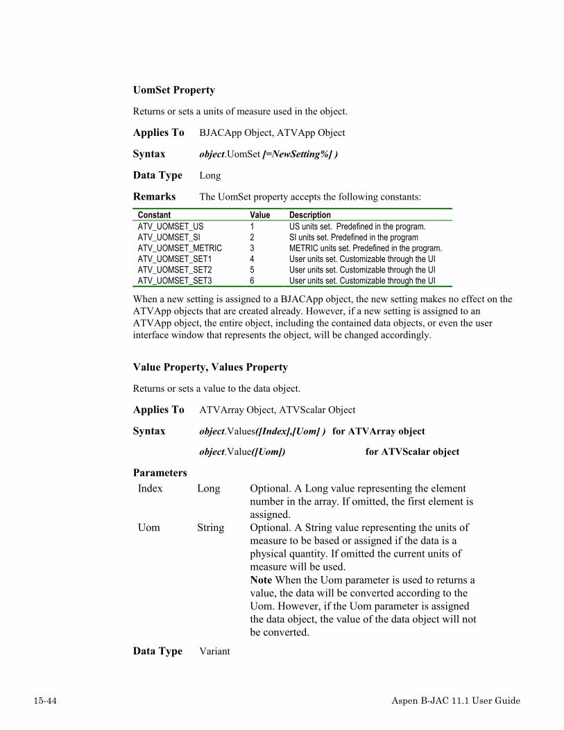
15-44 Aspen B-JAC 11.1 User Guide
UomSet Property
Returns or sets a units of measure used in the object.
Applies To BJACApp Object, ATVApp Object
Syntax object.UomSet [=NewSetting%] )
Data Type Long
Remarks The UomSet property accepts the following constants:
Constant Value DescriptionATV_UOMSET_US 1 US units set. Predefined in the program.ATV_UOMSET_SI 2 SI units set. Predefined in the programATV_UOMSET_METRIC 3 METRIC units set. Predefined in the program.ATV_UOMSET_SET1 4 User units set. Customizable through the UIATV_UOMSET_SET2 5 User units set. Customizable through the UIATV_UOMSET_SET3 6 User units set. Customizable through the UI
When a new setting is assigned to a BJACApp object, the new setting makes no effect on theATVApp objects that are created already. However, if a new setting is assigned to anATVApp object, the entire object, including the contained data objects, or even the userinterface window that represents the object, will be changed accordingly.
Value Property, Values Property
Returns or sets a value to the data object.
Applies To ATVArray Object, ATVScalar Object
Syntax object.Values([Index],[Uom] ) for ATVArray object
object.Value([Uom]) for ATVScalar object
ParametersIndex Long Optional. A Long value representing the element
number in the array. If omitted, the first element isassigned.
Uom String Optional. A String value representing the units ofmeasure to be based or assigned if the data is aphysical quantity. If omitted the current units ofmeasure will be used.Note When the Uom parameter is used to returns avalue, the data will be converted according to theUom. However, if the Uom parameter is assignedthe data object, the value of the data object will notbe converted.
Data Type Variant

Aspen B-JAC 11.1 User Guide 15-45
Remarks The Value or Values property is a variant type variable. Depending on theCategory property, it uses different VB data types to represent the data, and assigns differentundefined constants when the data is Empty, as shown in the following table:
Data Category VB Data Type UndefinedValue
Note
ATV_DATACATEGORY_PQ Single 0 Used for physical quantities. It returns 0 if thedata is empty. You should use the IsEmptymethod to check to see if the data is empty.
ATV_DATACATEGORY_LIST Long -30000 Used for StaticList. The Value propertyrepresents the index of an item in the list. TheText property stores the item. You must use avalid index number when you assign a valueto the property.
ATV_DATACATEGORY_NUM Single 0 User for numeric data except physicalquantities. You should use the IsEmptymethod to check the empty status.
ATV_DATACATEGORY_STR String “”ATV_DATACATEGORY_BOOL Boolean False
The optional parameter Index is used only for an ATVArray object. It represents the elementnumber in the array object.
The optional parameter Uom is a string description for the units of measure, for example, kg/sfor mass flow rate. You can use the Uom parameter to assign a new units of measure to thedata, or returns a value based the specified Uom parameter.
ExampleDim objHetran As ATVAppDim objArray As ATVArrayDim objScalar As ATVScalarDim Buf As Single. . .‘ Get the reference to the hot side flow rateSet objScalar = objHetran.Scalars(“FlRaHS”)
‘ Get the current value in kg/h no matter what units the data is‘ actually usingBuf = objScalar.Value(“kg/h”)
‘ Assign the 10000 lb/h to the dataobjScalar.Value(“lb/h”) = 10000.0 ‘ Now the data’s units is lb/h
‘ Get the reference to the specific heat for liquid cold sideSet objArray = objHetran.Arrays(“SpHtLiqCS“)
‘ Gets the value of the element #1 in the current unitsBuf = objArray.Values(1)
‘ Assign a value to the element and change the unitsobjArray.Values(1,”kJ/(kg*K)”) = 0.2. . .

15-46 Aspen B-JAC 11.1 User Guide
Visible Property
Returns or set a Boolean value that determines the ASPEN B-JAC user interface is visible orhidden.
Applies To BJACApp Object
Syntax object.Visible [=NewSetting]
Data Type Boolean
Error DescriptionsNumber Descriptions-1 Input is incomplete1000 An unknown error has occurred.1001 Unknown security error occurred.1002 Couldn't detect security key on your system.1003 Couldn't detect HASP single-user security key on your system.1004 Couldn't detect NetHASP key on your system or no active NetHASP server was found.1005 License to run the program has expired.1006 The program doesn't have enough BRUs to run.1007 Couldn't read security key.1008 Couldn't write to security key.1009 The security key date or time has been changed.1010 Failed to access NetHASP key.1011 General security key error.1012 Failed to access Aspen License Manager(ASPLM) or no active ASPLM was found.1013 Number of stations that may run the application at the same time has been exceeded.1014 No license was found to run the program.1101 EXCEPTION_ACCESS_VIOLATION has occurred.1102 EXCEPTION_BREAKPOINT has occurred.1103 EXCEPTION_DATATYPE_MISALIGNMENT has occurred.1104 EXCEPTION_SINGLE_STEP has occurred.1105 EXCEPTION_ARRAY_BOUNDS_EXCEEDED has occurred.1106 EXCEPTION_FLT_DENORMAL_OPERAND has occurred.1107 EXCEPTION_FLT_DIVIDE_BY_ZERO has occurred.1108 EXCEPTION_FLT_INEXACT_RESULT has occurred.1109 EXCEPTION_FLT_INVALID_OPERATION has occurred.1110 EXCEPTION_FLT_OVERFLOW has occurred.1111 EXCEPTION_FLT_STACK_CHECK has occurred.1112 EXCEPTION_FLT_UNDERFLOW has occurred.1113 EXCEPTION_INT_DIVIDE_BY_ZERO has occurred.1114 EXCEPTION_INT_OVERFLOW has occurred.1115 EXCEPTION_PRIV_INSTRUCTION has occurred.1116 EXCEPTION_NONCONTINUABLE_EXCEPTION has occurred.

Aspen B-JAC 11.1 User Guide 15-47
Number Descriptions1200 The file <$> contains an unrecognized format.1201 Error occurred while accessing a file.1300 Failed to load Aspen Properties Plus DLL.1301 Error occurred while executing Aspen Properties Plus.1400 Fatal error in Aspen Plus / BJAC interface
❖ ❖ ❖ ❖

15-48 Aspen B-JAC 11.1 User Guide

Aspen B-JAC 11.1 User Guide A-1
A Appendix
A Appendix................................................................................................................................................................................................................1
Tubing ...........................................................................................................................................................................................3Tube Wall Thickness..............................................................................................................................................................3Tube Low Fin Information .....................................................................................................................................................4Enhanced Surfaces Standard Sizes .........................................................................................................................................5
Pipe Properties...............................................................................................................................................................................7ANSI Pipe Dimensions...........................................................................................................................................................7DIN / ISO 4200 Pipe Dimensions ..........................................................................................................................................9Standard Nozzle Flange Ratings...........................................................................................................................................10
Material Selection........................................................................................................................................................................11Generic Materials List ..........................................................................................................................................................11Gaskets – hot side.................................................................................................................................................................12Gaskets – cold side...............................................................................................................................................................13Corrosion Table....................................................................................................................................................................14
Baffle Cuts...................................................................................................................................................................................18Single Segmental ..................................................................................................................................................................18Double Segmental ................................................................................................................................................................18Triple Segmental ..................................................................................................................................................................19
Asme Code Cases ........................................................................................................................................................................20ASME Code Case 2278........................................................................................................................................................20ASME Code Case 2290........................................................................................................................................................20
Technical References...................................................................................................................................................................22Introduction ..........................................................................................................................................................................22General .................................................................................................................................................................................23Shell Side Heat Transfer and Pressure Drop ........................................................................................................................25Tube Side Heat Transfer and Pressure Drop ........................................................................................................................31

A-2 Aspen B-JAC 11.1 User Guide

Aspen B-JAC 11.1 User Guide A-3
Tubing
Tube Wall Thickness
B.W.G. Gauge in mm
28 0.014 0.36
27 0.016 0.41
26 0.018 0.46
25 0.20 0.51
24 0.22 0.56
23 0.25 0.64
22 0.028 0.71
21 0.032 0.81
20 0.035 0.89
19 0.042 1.07
18 0.049 1.24
17 0.058 1.47
16 0.065 1.65
15 0.072 1.83
14 0.083 2.11
13 j0.095 2.41
12 0.109 2.77
11 0.120 3.05
10 0.134 3.40
9 0.148 3.76
8 0.165 4.19
7 0.180 4.57
6 0.203 5.16
5 0.220 5.59
4 0.238 6.05
3 0.259 6.58
2 0.284 7.21
1 0.300 7.62

A-4 Aspen B-JAC 11.1 User Guide
Tube Low Fin Information
Standard fin outside diameters
in.: 1.5 2.0 2.5 3.0 3.5
mm: 38 50 63 76 89
Program Default: Tube Outside Diameter + 0.75 in or 19.05 mm
Standard fin thickness
integral or extruded: 0.012-0.025 in or 0.3-0.7 mm
welded or wrapped: 0.025-0.165 in or 0.6-4 mm
in: 0.031 0.036 0.049 0.059
mm: 0.8 0.9 1.2 1.5
Program Default:
0.23 in or 0.58 mm for tube O.D. less than 2 in or 50.8
0.36 in or 0.91 mm for tube O.D. greater than 2 in or 50.8 mm

Aspen B-JAC 11.1 User Guide A-5
Enhanced Surfaces Standard SizesThe following are the standard available tube sizes that are available for theindicated enhance surfaces.
Manufacture-Type Tube OD, in Wall Thk, inWolverine TURBO B MHT
1 3/4" OD .051" WALL2 3/4" OD .054" WALL3 3/4" OD .059" WALL4 3/4" OD .065" WALL7 1" OD .053" WALL
Wolverine TURBO B LPD5 3/4" OD .051" WALL6 3/4" OD .057" WALL
Wolverine TURBO C MHT1 1" OD .052" WALL2 3/4" OD .051" WALL3 3/4" OD .054" WALL4 3/4" OD .058" WALL
Wolverine TURBO C LPD5 3/4" OD .051" WALL
Wolverine TURBO BII1 3/4" OD .049" WALL2 3/4" OD .051" WALL3 3/4" OD .058" WALL
Wolverine TURBO CII1 3/4" OD .047" WALL2 3/4" OD .050" WALL3 3/4" OD .056" WALL
Wolverine KORODENSE MHTWolverine KORODENSE LPD
1 5/8" OD .020" WALL2 5/8" OD .025" WALL3 5/8" OD .032" WALL4 5/8" OD .035" WALL5 5/8" OD .042" WALL6 5/8" OD .049" WALL7 5/8" OD .065" WALL8 3/4" OD .020" WALL9 3/4" OD .025" WALL10 3/4" OD .032" WALL11 3/4" OD .035" WALL12 3/4" OD .042" WALL13 3/4" OD .049" WALL14 3/4" OD .065" WALL15 7/8" OD .020" WALL16 7/8" OD .025" WALL17 7/8" OD .032" WALL18 7/8" OD .035" WALL19 7/8" OD .042" WALL20 7/8" OD .049" WALL21 7/8" OD .065" WALL22 1" OD .020" WALL23 1" OD .025" WALL24 1" OD .032" WALL25 1" OD .035" WALL26 1" OD .042" WALL

A-6 Aspen B-JAC 11.1 User Guide
27 1" OD .049" WALL28 1" OD .065" WALL29 1-1/8" OD .025" WALL30 1-1/8" OD .032" WALL31 1-1/8" OD .035" WALL32 1-1/8" OD .042" WALL33 1-1/8" OD .049" WALL34 1-1/8" OD .065" WALL35 1-1/4" OD .025" WALL36 1-1/4" OD .032" WALL37 1-1/4" OD .035" WALL38 1-1/4" OD .042" WALL39 1-1/4" OD .049" WALL40 1-1/4" OD .065" WALL

Aspen B-JAC 11.1 User Guide A-7
Pipe Properties
ANSI Pipe DimensionsANSI Pipe Dimensions Dimensions: inNom OD 0.75 1.0 1.25 1.5 2.0 2.5 3.0 3.5 4.0 5.0
Actual OD 1.050 1.315 1.660 1.900 2.375 2.875 3.500 4.000 4.500 5.563
-------------------------------------------------------------------------------
Sch 5S | 0.065 0.065 0.065 0.065 0.065 0.083 0.083 0.083 0.083 0.109
Sch 10S |0.083 0.109 0.109 0.109 0.109 0.120 0.120 0.120 0.120 0.134
Sch 10 | - - - - - - - - - -
Sch 20 | - - - - - - - - - -
Sch 30 | - - - - - - - - - -
Std | 0.113 0.133 0.140 0.145 0.154 0.203 0.216 0.226 0.237 0.258
Sch 40 | 0.113 0.133 0.140 0.145 0.154 0.203 0.216 0.226 0.237 0.258
Sch 60 | - - - - - - - - - -
Ext Str | 0.154 0.179 0.191 0.200 0.218 0.276 0.300 0.318 0.337 0.375
Sch 80 | 0.154 0.179 0.191 0.200 0.218 0.276 0.300 0.318 0.337 0.375
Sch 100 | - - - - - - - - - -
Sch 120 | - - - - - - - - 0.438 0.500
Sch 140 | - - - - - - - - - -
Sch 160 | 0.219 0.250 0.250 0.281 0.344 0.375 0.438 - 0.531 0.625
XX Str | 0.308 0.358 0.382 0.400 0.436 0.552 0.600 - 0.750 0.864
ANSI Pipe Dimensions Dimensions: inNom OD 6 8 10 12 14 16 18 20 22 24
Actual OD 6.625 8.625 10.75 12.75 14.0 16.0 18.0 20.0 22.0 24.0
-------------------------------------------------------------------------------
Sch 5S | 0.109 0.109 0.134 0.156 0.156 0.165 0.165 0.188 0.188 0.218
Sch 10S | 0.134 0.148 0.165 0.180 0.188 0.188 0.188 0.218 0.218 0.250
Sch 10 | - - - - 0.250 0.250 0.250 0.250 0.250 0.250
Sch 20 | - 0.250 0.250 0.250 0.312 0.312 0.312 0.375 0.375 0.375
Sch 30 | - 0.277 0.307 0.330 0.375 0.375 0.438 0.500 0.500 0.562
Std | 0.280 0.322 0.365 0.375 0.375 0.375 0.375 0.375 0.375 0.375
Sch 40 | 0.280 0.322 0.365 0.406 0.438 0.500 0.562 0.594 - 0.688
Sch 60 | - 0.406 0.500 0.562 0.594 0.656 0.750 0.812 0.875 0.969
Ext Str | 0.432 0.500 0.500 0.500 0.500 0.500 0.500 0.500 0.500 0.500
Sch 80 | 0.432 0.500 0.594 0.688 0.750 0.844 0.938 1.031 1.125 1.218
Sch 100 | - 0.594 0.719 0.844 0.938 1.031 1.156 1.281 1.375 1.531
Sch 120 | 0.562 0.719 0.844 1.000 1.094 1.219 1.375 1.500 1.625 1.812
Sch 140 | - 0.812 1.000 1.125 1.250 1.438 1.562 1.750 1.875 2.062
Sch 160 | 0.719 0.906 1.125 1.312 1.406 1.594 1.781 1.969 2.125 2.344
XX Str | 0.864 0.875 1.000 1.000 - - - - - -

A-8 Aspen B-JAC 11.1 User Guide
ANSI Pipe Dimensions Dimensions: mmNom OD 19 25 32 38 51 64 76 89 102 127
Actual OD 26.6 33.4 42.2 48.3 60.3 73.0 88.9 101.6 114.3 141.3
-------------------------------------------------------------------------------
Sch 5S | 1.6 1.6 1.6 1.6 1.6 2.1 2.1 2.1 2.1 2.7
Sch 10S | 2.1 2.7 2.7 2.7 2.7 3.0 3.0 3.0 3.0 3.4
Sch 10 | - - - - - - - - - -
Sch 20 | - - - - - - - - - -
Sch 30 | - - - - - - - - - -
Std | - 3.4 3.6 3.7 3.9 5.2 5.5 5.7 6.0 6.6
Sch 40 | 2.8 3.4 3.6 3.7 3.9 5.2 5.5 5.7 6.0 6.6
Sch 60 | - - - - - - - - - -
Ext Str | 3.9 4.5 4.9 5.1 5.5 7.0 7.6 8.1 8.6 9.5
Sch 80 | 3.9 4.5 4.9 5.1 5.5 7.0 7.6 8.1 8.6 9.5
Sch 100 | - - - - - - - - - -
Sch 120 | - - - - - - - - 11.1 12.7
Sch 140 | - - - - - - - - - -
Sch 160 | 5.5 6.4 6.4 7.1 8.7 9.5 11.1 - 13.5 15.9
XX Str | 7.8 9.1 9.7 10.2 11.1 14.0 15.2 16.2 17.1 19.1
ANSI Pipe Dimensions Dimensions: mmNom OD 152 203 254 305 356 406 457 508 559 610
Actual OD 168.3 219.1 273.1 323.9 355.6 406.4 457.2 508.0 558.8 609.6
-------------------------------------------------------------------------------
Sch 5S | 2.7 2.7 3.4 4.0 4.0 4.0 4.0 4.8 4.8 5.5
Sch 10S | 3.4 3.7 4.1 4.5 4.8 4.8 4.8 5.5 5.5 6.3
Sch 10 | - - - - 6.3 6.3 6.3 6.3 6.3 6.3
Sch 20 | - - - - 7.9 7.9 7.9 9.5 9.5 9.5
Sch 30 | - 7.0 7.8 8.4 9.5 9.5 11.1 12.7 12.7 14.3
Std | 7.1 8.2 9.3 9.5 9.5 9.5 9.5 9.5 9.5 9.5
Sch 40 | 7.1 8.2 9.3 10.3 11.1 12.7 14.3 15.1 - 17.5
Sch 60 | - 10.3 12.7 14.3 15.1 16.7 19.1 20.6 22.2 24.6
Ext Str | 11.0 12.7 12.7 12.7 12.7 12.7 12.7 12.7 12.7 12.7
Sch 80 | 11.0 12.7 15.1 17.5 19.1 21.4 23.8 26.2 28.6 30.9
Sch 100 | - 15.1 18.3 21.4 23.8 26.2 29.4 32.5 34.9 38.9
Sch 120 | 13.5 18.3 21.4 25.4 27.8 31.0 34.9 38.1 - 46.0
Sch 140 | - 20.6 25.4 28.6 31.8 36.5 39.7 44.5 - 52.4
Sch 160 | 18.3 23.0 28.6 33.3 35.7 40.5 45.2 50.0 - 59.5
XX Str | 21.9 22.2 25.4 25.4 - - - - - -

Aspen B-JAC 11.1 User Guide A-9
DIN / ISO 4200 Pipe Dimensions
DIN / ISO 4200 Pipe Dimensions Dimensions: mmNom OD 20 25 32 40 50 65 80 100 125 150
Actual OD 26.9 33.7 42.4 48.3 60.3 76.1 88.9 114.3 139.7 168.3
-------------------------------------------------------------------------------
Row A | 1.6 1.6 1.6 1.6 1.6 1.6 2.0 2.0 2.0 2.0
Row B | - 2.0 2.0 2.0 2.0 2.3 2.3 2.3 2.3 2.3
Row C | - - - - 2.3 2.6 2.9 2.9 3.2 3.2
Row D | 1.8 2.0 2.3 2.3 2.3 2.6 2.9 3.2 3.6 4.0
Row E | 2.0 2.3 2.6 2.9 2.9 2.9 3.2 3.6 4.0 4.5
Row F | 3.2 3.2 3.6 3.6 4.0 5.0 5.6 6.3 6.3 7.1
Row G | 4.0 4.5 5.0 5.0 5.6 7.1 8.0 8.8 10 11
DIN / ISO 4200 Pipe Dimensions Dimensions: mmNom OD 200 250 300 350 400 450 500 600 700 800
Actual OD 219.1 273 323.9 355.6 406.4 457 508 610 711 813
-------------------------------------------------------------------------------
Row A | 2.0 2.0 2.6 2.6 2.6 3.2 3.2 3.2 4.0 4.0
Row B | 2.6 3.6 4.0 4.0 4.0 4.0 5.0 5.6 6.3 7.1

A-10 Aspen B-JAC 11.1 User Guide
Row C | 3.6 4.0 4.5 5.0 5.0 5.0 5.6 6.3 7.1 8.0
Row D | 4.5 5.0 5.6 5.6 6.3 6.3 6.3 6.3 7.1 8.0
Row E | 6.3 6.3 7.1 8.0 8.8 10 11 12.5 14.2 16
Row F | 8.0 10 10 11 12.5 14.2 16 17.5 20 22.2
Row G | 12.5 14.2 16 17.5 20 22.2 25 30 32 36
Standard Nozzle Flange RatingsANSI: 50 300 400 600 900 1500 2500
ISO: 10 16 20 25 40 50 100
DIN: 10 16 25 40 63 100 160 250 320 400

Aspen B-JAC 11.1 User Guide A-11
Material Selection
Generic Materials List
Abbrev Material
CS Carbon Steel
C½Mo Low Alloy Steel C½Mo
½Cr½Mo Low Alloy Steel ½Cr½Mo
Cr½Mo Low Alloy Steel Cr½Mo
1¼Cr½Mo Low Alloy Steel 1¼Cr½Mo
SS 304 High Alloy Steel Grade 304
SS 304L High Alloy Steel Grade 304L
SS 316L High Alloy Steel Grade 316L
SS 310S High Alloy Steel Grade 310S
SS 347 High Alloy Steel Grade 347
SS 310S High Alloy Steel Grade 310S
SS XM-27 High Alloy Steel Grade XM-27
SS 410 High Alloy Steel Grade 410

A-12 Aspen B-JAC 11.1 User Guide
Abbrev Material
NI 200 Nickel Alloy 200
NI 201 Nickel Low Carbon Alloy 201
Monel Nickel Alloy 400 (Monel)
Inconel Nickel Alloy 600 (Inconel)
NI 800 Nickel Alloy 800
NI 825 Nickel Alloy 825 (Incoloy 825)
Hast. B Nickel Alloy B (Hastelloy B)
Hast. C Nickel Alloy C (Hastelloy C)
Hast. G Nickel Alloy G (Hastelloy G)
NI 20 Nickel Alloy 20 Cb (Carpenter 20)
Titanium Titanium
Cu-Ni 70/30 Copper-Nickel 70/30 Alloy CDA 715
Cu-Ni 90/10 Copper-Nickel 90/10 Alloy CDA 706
Cu-Si Copper-Silicon Alloy CDA 655
NavBrass Naval Brass Alloy 464
AlBronze Aluminum-Bronze Alloy 630
AlBrass Aluminum-Brass Alloy 687
Admiralty Admiralty Alloy 443
Tantalum Tantalum
Zirconium Zirconium
Gaskets – hot sideSpecify one of the following generic materials for the gaskets:• compressed fiber• flat metal jacketed fiber• solid flat metal• solid teflon• graphite• spiral wound• ring joint• self-energized• elastomers

Aspen B-JAC 11.1 User Guide A-13
Gaskets – cold sideSpecify one on the following generic gasket materials:• compressed fiber• flat metal jacketed fiber• solid flat metal• solid teflon• graphite• spiral wound• ring joint• self-energized
elastomers

A-14 Aspen B-JAC 11.1 User Guide
Corrosion TableThe following table is provided as a quick reference for acceptable materialsof construction. The corrosion ratings are at a single temperature (usually20 C) and a single concentration. A final decision on material selection shouldbe based on operating temperature, actual concentration and galvanic action.
A = Excellent E = ExplosiveB = Good I = IgnitesC = Fair - = Information not availableD = Not suitable
The material abbreviations used in the table are as follows:CS Carbon steelCu CopperAdmi AdmiraltyCuSi Copper siliconCN90 Cupro-nickel 90-10CN70 Cupro-nickel 70-30SS304 Stainless steel 304SS316 Stainless steel 316Ni NickelMonel MonelInco InconelHast HastelloyTi TitaniumZr ZirconiumTa Tantalum
Corrosion Table CS Cu Ad Cu CN CN SS SS Ni Mo In Ha Ti Zr Tami Si 90 70 304 316 nel co st
Acetaldehyde A E E E E E A A A A A A B - AAcetic acid D D D D C C A A D A B A A A AAcetic anhydride D B C B B B B B B B B A A A BAcetone A A A A A A A A B A A B A - AAcetylene A E E E E E A A A A A A A - AAluminum chloride D D D D D D D D C B D A A A AAluminum hydroxide B B B B B B B B B B B B - - BAmmonia (anhydrous) A A A A A A A A B A B B A - AAmmonium chloride D D D D D D B B B B B B A A AAmmonium sulfate C C C C C C C C B A B B A A AAmmonium sulfite D B B B B B C C D D D - A - A
Corrosion Table CS Cu Ad Cu CN CN SS SS Ni Mo In Ha Ti Zr Tami Si 90 70 304 316 nel co st
Amyl acetate B A A B A A A A A A A B A - AAniline A D D D D D A A B B B B A - AAroclor B A A A A A B B A A A A A - ABarium chloride B B C B B B B B B B B B A A ABenzaldehyde B B B B B B B B B B B A A - ABenzene A A A A A A B B B B B B A - ABenzoic acid D B B B B B B B B B B B A - ABoric acid D B B B B B A A B B B A A - AButadiene A A A A A A A A A A A A A - A

Aspen B-JAC 11.1 User Guide A-15
Butane A A A A A A A A A A A A A - AButanol A A A A A A A A A A A A A - AButyl acetate A B B B B B B B A B A B A - A
Corrosion Table CS Cu Ad Cu CN CN SS SS Ni Mo In Ha Ti Zr Tami Si 90 70 304 316 nel co st
Butyl chloride A A A A A A A A A A A A A - ACalcium chloride B B C B B B C B A A A B A A ACalcium hydroxide B B B B B B B B B B B B A - ACarbon dioxide(wet) C C C C C C A A A A A A A - ACarb. tetrachloride B B B B B B B B A A A B A A ACarbonic acid C C C C C C B B B C A A A - AChlorine gas (dry) B B B B B B B B B B A B I A AChloroform (dry) B B B B B B B B A A B B A A AChromic acid D D D D D D C B D D B B B A ACitric acid D C C C C C C B B B A C A A ACreosote B B B B B B B B B B B B A - ADibutylphthalate A A A A A A B B B B B B A - A
Corrosion Table CS Cu Ad Cu CN CN SS SS Ni Mo In Ha Ti Zr Tami Si 90 70 304 316 nel co st
Dichlorobenzene B B B B B B B B B B B B B - ADichlorofluorometh. A A A A A A A B B B B A A - ADiethanolamine A B B B B B A A A A A A A - ADiethyl etheride B B B B B B B B B B B B A - ADiethylene glycol A B B B B B A A B B B B A - ADiphenyl B B B B B B B B B B B B A - ADiphenyl oxide B B B B B B B B B B B B A - AEthane A A A A A A A A A A A A A - AEthanolamine B B B B B B A B B B B B B - AEther B B B B B B B B B B B B A - AEthyl acetate (dry) B B B B B B B B B B B B A - AEthyl alcohol B B B B B B B B B B B A A A A

A-16 Aspen B-JAC 11.1 User Guide
Corrosion Table CS Cu Ad Cu CN CN SS SS Ni Mo In Ha Ti Zr Tami Si 90 70 304 316 nel co st
Ethyl ether B B B B B B B B B B B B A - AEthylene A A A A A A A A A A A A A - AEthylene glycol B B B B B B B B B B B B A - AFatty acids D D D D D D D A B C B A B - AFerric chloride D D D D D D D D D D D B A D AFerric sulfate D D D D D D B B D D D A A - AFerrous sulfate D B B B B B B B D D D B A - AFormaldehyde D B B B B B B B B B B B B - AFurfural B B B B B B B B B B B B A - AGlycerine A A A A A A A A A A A A A - AHexane A A A A A A A A A A A A A - AHydrochloric acid D D D D D D D D D D D B D D A
Corrosion Table CS Cu Ad Cu CN CN SS SS Ni Mo In Ha Ti Zr Tami Si 90 70 304 316 nel co st
Hydrofluoric acid D C D D D C D D D C D A D D DIodine D D D D D D D D D D D B D - AIsopropanol A B B B B B B B B B B B A - ALactic acid D B C B B B B A B C A A A A ALinseed oil A B B B B B A A B B B B A - ALithium chloride B B B B B B B A A A A A - - ALithium hydroxide B B B B B B B B B B B B - - AMagnesium chloride B B C B B B B B A B A A A A AMagnesium hydroxide B B B B B B B B B B B B A - BMagnesium sulfate B B B B B B A A B B B A A A AMethane A A A A A A A A A A A A A A AMethallyamine C B B B B B B B B C B B B - A
Corrosion Table CS Cu Ad Cu CN CN SS SS Ni Mo In Ha Ti Zr Tami Si 90 70 304 316 nel co st
Methyl alcohol B B B B B B B B B A B A A A AMethyl chloride-dry A A A A A A A A B B B B A - AMethylene chloride B B B B B B B B B B B B B - AMonochlorobenzene B B B B B B B B A A A B B - AM.dichl.difl.mehane A A A A A A A A A A A A A - AMonoethanolamine B B B B B B B B B B B - - - ANaptha A B B B B B B B B B B B B - ANapthalene A B B B B B A A A A A B B - ANickel chloride D B B B B B B B D B D A A A ANickel sulfate D B B B B B B B B B B B B A ANitric acid D D D D D D B B D D D D A B ANitrous acid D D D D D D B B D D D - - - A

Aspen B-JAC 11.1 User Guide A-17
Corrosion Table CS Cu Ad Cu CN CN SS SS Ni Mo In Ha Ti Zr Tami Si 90 70 304 316 nel co st
Oleic acid B B B B B B B B A A A B B B BOxalic acid D B B B B B B B C B B B D B APerchloric acid-dry D D D D D D B B D D D - - - APerchloroethylene A B B B B B B B A A A - A - APhenoldehyde B B B B B B B B B A B A A - APhosphoric acid D D D D D D B B D D B A C D BPhthalic anhydride B B B B B B B B B B B B - - APotassium bicarbon. B B B B B A B B B B B B A - APotassium carbonate B B B B B B B B B B B B A - APropylene glycol B B B B B B B B B B B B A - APyridine A B B B B B B B B B B B B - ARefrigerant 12 A A A A A A A B B B B A A - A
Corrosion Table CS Cu Ad Cu CN CN SS SS Ni Mo In Ha Ti Zr Tami Si 90 70 304 316 nel co st
Refrigerant 22 A A A A A A A A A A A A A - ASeawater C B A B A A A A B A B B A A ASilver chloride D D D D D D D D D D C B B - ASilver nitrate D D D D D D B B D D B B A A ASodium acetate D B B B B B B B B B B B B - ASodium hydroxide D D D D D D D D A B B B B B DSodium nitrate B B B B B B A A B B A B A - ASodium sulfate B B B B B B B A B B B B A - ASulfur dioxide(dry) B B B B B B B B B B B B A - ASulfuric acid D D D D D D D D D D D B D A AToluene A A A A A A A A A A A A A A ATrichlorethylene B B B B B B B B A A B A A A A
Corrosion Table CS Cu Ad Cu CN CN SS SS Ni Mo In Ha Ti Zr Tami Si 90 70 304 316 nel co st
Turpentine B B B B B B B B B B B B B - AVinyl chloride(dry) A B C B B B B A A A A A A - AWater (fresh) C A A A A A A A A A A A A A AWater (sea) C B A B A A A A B A B B A A AXylene B A A A A A A A A A A A A A AZinc chloride D D D D D D B B B A D B A A AZinc sulfate D B B B B B B A B B A B A - A

A-18 Aspen B-JAC 11.1 User Guide
Baffle Cuts
Single SegmentalIn all Aspen B-JAC programs, the single segmental baffle cut is always defined as thesegment opening height expressed as a percentage of the shell inside diameter.
Typical baffle cut: 15% to 45%
Double SegmentalIn all Aspen B-JAC programs, the double segmental cut is always defined as the segmentheight of the innermost baffle window expressed as a percentage of the shell inside diameter.In the output, the baffle cut will be printed with the percent of the inner window / percent ofone of the outer windows. The area cut away is approximately equal for each baffle.
Typical baffle cut: 20% to 42%

Aspen B-JAC 11.1 User Guide A-19
Triple SegmentalIn all Aspen B-JAC programs, the triple segmental cut is always defined as the segmentheight of the innermost baffle window expressed as a percentage of the shell tube insidediameter. In the output, the baffle cut will be printed with the percent of the innermostwindow / percent of one intermediate window / percent of one outermost window. The areacut away is approximately equal for each baffle.
Typical baffle cut: 22% to 32%

A-20 Aspen B-JAC 11.1 User Guide
Asme Code Cases
ASME Code Case 2278Alternative Method for Calculating Maximum Allowable Stresses Based on a Factor of 3.5 onTensile Strength Section II and Section VIII Div. 1.
Important items are:
• These materials are the same as previously used. No chemical specificationshave been changed.
• Materials are limited to those listed in the tables in ASME-VIII Div.1 (forexample, UCS-23).
• The maximum permitted temperature for these materials are less than the originallistings.
• Only materials with both tensile strength and yield strength tables can be used(ASME Section II, Part D - if the materials are not listed on tables U and Y-1,they can not be used per code case 2278).
• New figure provided for the calculation of the reduction in minimum designmetal temperature without impact testing.
• The allowable stress values are calculated from the tensile strength and the yieldstrength.
• The application of this case is not recommended for gasketed joints or otherapplications where slight distortion can cause leakage or malfunction.
• The hydrostatic test factor is reduced from 1.5 to 1.3.• All other code requirements apply (external pressure charts, etc.).
When using code case 2278, no reference is made to this case when the program listsmaterials. It is recommended that you note the use of code case in you file headingsdescription. You select the usage of code case 2278 as an input in the program optionssection.
ASME Code Case 2290Alternative Maximum Allowable Stresses Based on a Factor of 3.5 on Tensile Strength SectionI. Part D and Section VIII Division 1.
Important items are:

Aspen B-JAC 11.1 User Guide A-21
• These materials are the same as previously used. No chemical specificationshave been changed.
• The alternative maximum allowable stresses are listed in Table 1 of code case2290 (same format as Section II, Part D materials).
• New figure provided for the calculation of the reduction in minimum designmetal temperature without impact testing.
• The application of this case is not recommended for gasketed joints or otherapplications where slight distortion can cause leakage or malfunction.
• The hydrostatic test factor is reduced from 1.5 to 1.3.• All other code requirements appl (external pressure charts, etc.).
When using code case 2290, the program will access a new database in which all materialsend with the characters '2290'. Therefore, the user and inspector will know what materials fallwithin this code case. This new database will be listed in the user's interface as 'ASME-2290'.All materials in the new database start from the B-JAC number 5000 (5000-5999). The newdatabase filenames for the engine are AS2290P.PDA and NAS2290I.PDA. The user selectsthe usage of code case 2290 by selecting any available material in the 5000 series.

A-22 Aspen B-JAC 11.1 User Guide
Technical References
IntroductionAspen B-JAC updates its programs with the best of the most recent correlations for heattransfer and pressure drop available from research and published literature sources. Thereferences have been categorized into their applicable areas as follows:
General Shell Side Heat Transfer & Pressure Drop• No Phase Change• Vaporization• Condensation
Tube Side Heat Transfer & Pressure Drop• No Phase Change• Vaporization• Condensation
Although AspenTech does not publish the exact formulas used in the program, we will gladlydirect you to the correct source in the published literature pertaining to your question.
AspenTech continually examines new correlations as they become available and incorporatesthem into the Aspen B-JAC program only after extensive evaluation. This evaluation includescomparisons of results between new and old correlations, field data from a multitude of unitscurrently in service, and many years of design experience.
Please do not request copies of references from AspenTech. Request for copies of articlesshould be made to :
Engineering Societies Library345 East 47th StreetNew York, NY 10017U. S. A.

Aspen B-JAC 11.1 User Guide A-23
GeneralPerry's Chemical Engineers' Handbook, Sixth Edition, McGraw-Hill, 1984
General Discussion on Heat Transfer, Institution of Mechanical Engineers London, 1951
Practical Aspects of Heat Transfer, AIChE Technical Manual, 1976
Gas Engineers Handbook, C. George Segeler, Industrial Press, 1974
Heat Transfer and Fluid Flow Data Books, General Electric, 1984
Engineering Data Book, Gas Processors Suppliers Association, 1979
Standard Handbook of Engineering Calculations, Second Edition, Tyler G. Hicks, McGraw-Hill, 1985
Heat Exchanger Design Handbooks, Volumes 1-5, Hemisphere Publishing Corporation, 1984
International Heat Transfer Conference Proceedings, Hemisphere Publishing Corporation,Heat Transfer 1978, TorontoHeat Transfer 1982, MunichHeat Transfer 1986, San FranciscoHeat Transfer 1990, Jerusalem
AIChE Symposium Heat Transfer SeriesSeattle 82 Volume 64, 1968Philadelphia 92 Volume 65, 1969Minneapolis 102 Volume 66, 1970Tulsa 118 Volume 68, 1972Fundamentals 131 Volume 69, 1973Research & Design 138 Volume 70, 1974St. Louis 164 Volume 73, 1977Research & Application 174 Volume 74, 1978Seattle 225 Volume 79, 1983Niagara Falls 236 Volume 80, 1984Denver 245 Volume 81, 1985
Process Heat Transfer, Donald Q. Kern, McGraw-Hill, 1950
Compact Heat Exchangers, Third Edition, Kays & London, McGraw-Hill, 1984
Process Design for Reliable Operations, Norman P. Lieberman, Gulf Publishing Company,1983
Heat Exchangers: Design and Theory Sourcebook, Afgan & Schlunder, McGraw Hill, 1974
Heat Exchangers Thermal-Hydraulic Fundamentals and Design, Kakac, Bergles & Mayinger,McGraw-Hill, 1981
Convective Boiling and Condensation, John G. Collier, McGraw-Hill, 1972
Industrial Heat Exchangers, A Basic Guide, G. Walker, McGraw-Hill, 1982

A-24 Aspen B-JAC 11.1 User Guide
Heat Transfer, J.P. Holman, McGraw-Hill, 1981
Heat Transfer in Counterflow, Parallel Flow and Cross Flow, Helmuth Hausen, McGraw-Hill,1983
Extended Surface Heat Transfer, D.O. Kern & A.D. Kraus, McGraw-Hill, 1972
Heat Exchangers, Theory and Practice, Taborek, Hewitt & Afgan, McGraw-Hill, 1983
Two-Phase Flow and Heat Transfer in the Power and Process Industries, Bergles, Collier,Delhaye, Hewitt & Mayinger, McGraw-Hill, 1981
Standards of Tubular Exchangers Manufacturers Association, Seventh Edition, TEMA, 1988
Wolverine Trufin Engineering Data Book, Wolverine Tube Division, 1967
Heat Transfer Pocket Handbook, Nicholas P. Cheremisinoff, Gulf Publishing Company, 1984
Fluid Flow Pocket Handbook, Nicholas P. Cheremisinoff, Gulf Publishing Company, 1984
Handbook of Chemical Engineering Calculations, Chopey & Hicks, McGraw-Hill, 1984
Heat Exchangers for Two-Phase Applications, ASME, HTD-Vol. 27, 1983
Reprints of AIChE Papers, 17th National Heat Transfer Conference, Salt Lake City, 1977
Standards for Power Plant Heat Exchangers, Heat Exchange Institute Inc., 1980
A Reappraisal of Shellside Flow in Heat Exchangers, ASME HTD-36, 1984
Shellside Waterflow Pressure Drop and Distribution in Industrial Size Test Heat Exchanger,Halle & Wambsganss, Argonne National Laboratory, 1983
Basic Aspects of Two Phase Flow and Heat Transfer, ASME, HTD-Vol. 34, 1984
ASME Heat Transfer Publications, 1979, 18th National Heat Transfer Conference,Condensation Heat Transfer, & Advances in Enhanced Heat Transfer
Shell and Tube Heat Exchangers, Second Symposium, American Society for Metals,Houston, Texas, September, 1981
Two-Phase Heat Exchanger Symposium 23rd National Heat Transfer Conference, Denver,Colorado, HTD-Vol.44 August, 1985
Advances in Enhanced Heat Transfer 23rd National Heat Transfer Conference, Denver,Colorado, HTD-Vol.43 August, 1985
Heat Tranfer Equipment Design, R.K. Shah, Subbarao, and R.A. Mashelkar, HemispherePublishing Corporation, 1988
Heat Transfer Design Methods, Edited by John J. McKetta, Marcel Dekker Inc., 1992
Boilers Evaporators & Condesers, Sadik Kakac, John Wiley & Sons Inc., 1991
Enhanced Boiling Heat Transfer, John R. Thome, Hemisphere Publishing Corporation, 1990

Aspen B-JAC 11.1 User Guide A-25
Handbook of Heat Transfer Applications Second Edition Editors W.M. Rohsenow, J.P.Hartnett and Ejup N. Ganic, McGraw-Hill Book Co., 1985
Piping Handbook, Sixth Edition, Mobinder L. Nayyar, McGraw-Hill Inc., 1992
Practical Aspects of Heat Transfer, Proceedings of 1976 Fall Lecture Series of New Jersey--North Jersey Sections of AICHE, 1976.
Air Cooled Heat Exchangers For General Refinery Services, API Standard 661 SecondEdition, January 1978.
ESCOA Fintube Manual, Chris W. Weierman, ESCOA Fintube Corporation
Moore Fan Company Manual, Moore Fan Company, 1982.
Heat Transfer: Research and Application, ed. John Chen, AIChE Symposium Series, No.174, Vol. 74, 1978
Heat Transfer—Seattle 1983, Nayeem M. Farukhi, AIChE Symposium Series, No. 225, Vol.79, 1983.
Principles of Heat Transfer, Frank Kreith, International Textbook Company, 1958.
Fundamentals of Heat Transfer, S. S. Kutateladze, Academic Press, 1963.
NGPSA Engineering Data Book, Natural Gas Processors Suppliers Association, 1979.
“Design of Air-Cooled Exchangers,” Robert Brown, Chemical Engineering, March 27, 1978.
“Process Design Criteria,” V. Ganapathy, Chemical Engineering, March 27, 1978.
Shell Side Heat Transfer and Pressure Drop
No Phase Change
Stream Analysis Type Correlations
Shell Side Characteristics of Shell and Tube Heat Exchangers, Townsend Tinker, ASMEPaper No. 56-A-123.
Exchanger Design Based on the Delaware Research Program, Kenneth J. Bell,PETRO/CHEM, October, 1960
Heat Exchanger Vibration Analysis, A. Devore, A. Brothman, and A. Horowitz, PracticalAspects of Heat Transfer, (Proceedings of 1976 Fall Lecture Series of New Jersey), AIChE
A-26 Aspen B-JAC 11.1 User Guide
The Effect of Leakage Through the Longitudinal Baffle on the Performance of Two-PassShell Exchangers, T. Rozenman and J. Taborek AIChE Symposium Series Heat TransferTulsa 118, Volume 68, 1972
Patterns of Fluid Flow in a Shell-and-Tube Heat Exchanger, J.A. Perez and E.M. Sparrow,Heat Transfer Engineering, Volume 5 Numbers 3-4, 1984, Hemisphere PublishingCorporation
Solution of Shell Side Flow Pressure Drop and Heat Transfer, Stream Analysis Method, J.W.Palen and Jerry Taborek, AIChE Symposium Series Heat Transfer-Philadelphia 92, Volume65, 1969
Shellside Waterflow Pressure Drop and Distribution in Industrial Size Test Heat Exchanger,H. Halle and M.W. Wambsganss, ANL-83-9 Argonne National Laboratory, 1983
A Reappraisal of Shellside Flow in Heat Exchangers, HTD-Vol. 36, ASME, 1984
Delaware Method for Shell Side Design, Kenneth J. Bell, Heat Exchangers Thermal-Hydraulic Fundamentals and Design, McGraw-Hill Book Co., 1981
Low Fin Tube Correlations
Handbook of Chemical Engineering Calculations, Nicholas P. Chopey and Tyler G. Hicks,McGraw-Hill Book Co., 1984
Wolverine Trufin Engineering Data Book, Wolverine Division, UOP Inc.
Fine-Fin Tubing Specifications, High Performance Tube Inc., 2MI/78
Transfer Rates at the Caloric Temperature
Improved Exchanger Design, Riad G. Malek, Hydrocarbon Processing, May 1973
Process Heat Transfer, Donald Q. Kern, McGraw Hill Book Co., 1950
The Caloric Temperature Factor for a 1-2 Heat Exchanger with An Overall Heat TransferCoefficient Varying Linearly with Tube Side Temperature, R.B. Bannerot and K.K. Mahajan,AIChE Symposium Series 174, Volume 74, Heat Transfer - Research and Applications, 1978
Grid Baffle Correlations
The Energy-Saving NESTS Concept, Robert C. Boyer and Glennwood K. Pase, Heat TransferEngineering, Vol. 2, Number 1, Hemisphere Publishing Corporation, July-Sept. 1980
Thermal Design Method for Single-Phase RODBaffle Heat Exchangers, C.C. Gentry andW.M. Small, Phillips Petroleum Company, 1981

Aspen B-JAC 11.1 User Guide A-27
RODbaffle Exchanger Thermal-Hydraulic Predictive Models Over Expanded Baffle-Spacingand Reynolds Number Ranges, C. C. Gentry and W. M. Small, AIChE Symposium Series 245,Vol 81 Heat Transfer-Denver, 1985
RODbaffle Heat Exchanger Thermal-Hydraulic Predictive Methods for Bare and Low-FinnedTubes, C. C. Gentry, R. K. Young, W. M. Small, AIChE Symposium Series Heat Transfer -Niagara Falls 236, Volume 80, 1984
Phase Change - Natural and Forced Circulation Boiling
Thermal Design of Horizontal Reboilers, James R. Fair and Abraham Klip, ChemicalEngineering Progress, March 1983
Two-Phase Flow and Heat Transfer in the Power and Process Industries, A. E. Bergles, J. G.Collier, J. M. Delhaye, G. F. Hewitt, and F. Mayinger, McGraw-Hill, 1981
Circulation Boiling, Model for Analysis of Kettle and Internal Reboiler Performance, J. W.Palen and C. C. Yang, Heat Exchangers for Two-Phase Applications, ASME HTD-Vol 27,July 1983.
A Prediction Method for Kettle Reboilers Performance, T. Brisbane, I. Grant and P. Whalley,ASME 80-HT-42
Nucleate Boiling: A Maximum Heat Flow Correlation for Corresponding States Liquids, C.B. Cobb and E. L. Par, Jr., AIChE Symposium Series Heat Transfer Philadelphia 92, Volume65, 1969
Boiling Coefficients Outside Horizontal Plain and Finned Tubes, John E. Myers and DonaldL. Katz, Refrigerating Engineering, January, 1952
Forced Crossflow Boiling in an Ideal In-Line Tube Bundle, G. T. Pooley, T. Ralston, and I. D.R. Grant, ASME 80-HT-40
Characteristics of Boiling Outside Large-Scale Horizontal Multitube Bundles, J. W. Palen, A.Yarden, and J. Taborek, AIChE Symposium Series Heat Transfer - Tulsa 118, Volume 68,1972
A Simple Method for Calculating the Recirculating Flow in Vertical Thermosyphon andKettle Reboilers", P.B. Whalley and D. Butterworth, Heat Exchangers for Two-PhaseApplications, ASME HTD-Vol.27, July 1983
Analysis of Performance of Full Bundle Submerged Boilers, By P. Payvar, Two-Phase HeatExchanger Symposium, ASME HTD-Vol.44, August 1985
Enhanced Boiling Heat Transfer, Hemisphere Publishing Corporation, 1990
Phase Change - Condensation
Handbook of Chemical Engineering Calculations, Nicholas P. Chopey and Tyler G. Hicks,McGraw-Hill Book Company, 1984

A-28 Aspen B-JAC 11.1 User Guide
Heat Transfer and Two-Phase Flow During Shell-Side Condensation, P. J. Marto, HeatTransfer Engineering, Vol. 5, Number 1-2, 1984
Process Heat Transfer, Donald Q. Kern, McGraw-Hill Book Company, 1950
Design Parameters for Condensers and Reboilers, P. C. Lord, R. E. Minton and R. P. Slusser,Chemical Engineering, March 23, 1970
Condensation of Immiscible Mixtures, S. H. Bernhardt, J.J. Sheridan, and J. W. Westwater,AIChE Symposium Heat Transfer-Tulsa No. 118, Vol. 68, 1972
Design of Cooler Condensers for Mixtures of Vapor with Noncondensing Gases, A. P.Colburn and O. A. Hougen, Industrial and Engineering Chemistry, November 1939
Simplify Design of Partial Condensers, J. Starzewski, Hydrocarbon Processing, March 1981
Calculate Condenser Pressure Drop, John E. Diehl, Petroleum Refiner, October 1957
Two-Phase Pressure Drop for Horizontal Crossflow Through Tube Banks, J. E. Diehl and C.H. Unruh, Petroleum Refiner, October 1958
Mean Temperature Difference for Shell-And-Tube Heat Exchangers with Condensing on theShell Side, Robert S. Burligame, Heat Transfer Engineering, Volume 5, Numbers 3-4, 1984
An Assessment of Design Methods for Condensation of Vapors from a Noncondensing Gas,J. M. McNaught, Heat Exchanger Theory and Practice, McGraw-Hill Book Co., 1983
A Multicomponent Film Model Incorporating a General Matrix Method of Solution to theMaxwell-Stefan Equations, AIChE Journal, Vol 22, March 1976
Modified Resistance Proration Method for Condensation of Vapor Mixtures, R. G. Sardesai,J. W. Palen, and J. Taborek, AIChE Symposium Series Heat Transfer - Seattle 225, Volume79, 1983
An Approximate Generalized Design Method for Multicomponent Partial Condensers, K. J.Bell and M. A. Ghaly, AIChE Symposium Series Heat Transfer No. 131, Vol 69, 1973
Rating Shell-and-Tube Condensers by Stepwise Calculations, R. S. Kistler, A. E. Kassem, andJ. M. Chenoweth, ASME 76-WA/HT-5, 1976
Two-Phase Flow on the Shell-Side of a Segmentally Baffled Shell-and-Tube Heat Exchanger,I. D. R. Grant and D. Chismolm, ASME 77-WA/HT-22, 1977
Shellside Flow in Horizontal Condensers, I. D. R. Grant, D. Chisholm, and C. D. Cotchin,ASME 80-HT-56, 1980
Critical Review of Correlations for Predicting Two-Phase Flow Pressure Drop Across TubeBanks, K. Ishihara, J. W. Palen, and J. Taborek, ASME 77-WA/HT-23
Design of Binary Vapor Condensers Using the Colburn-Drew Equations, B C. Price and K. J.Bell, AIChE Symposium Series No. 138, Volume 74, 1974
Theoretical Model for Condensation on Horizontal Integral-Fin Tubes, T.M. Rudy and R. L.Webb, AIChE Symposium Series Heat Transfer Seattle 225, Volume 79, 1983

Aspen B-JAC 11.1 User Guide A-29
Condensers: Basic Heat Transfer and Fluid Flow, D. Butterworth, Heat Exchangers Thermal-Hydraulic Fundamentals and Design, McGraw-Hill Book Company, 1981
Condensers: Thermohydraulic Design, D. Butterworth, Heat Exchangers Thermal-HydraulicFundamentals and Design, McGraw-Hill Book Company, 1981

A-30 Aspen B-JAC 11.1 User Guide
High Fin Heat Transfer & Pressure Drop
“Fired Heaters,” Herbert L. Berman, Chemical Engineering, June 19, 1978.
“Bond Resistance of Bimetalic Finned Tubes,” E.H. Young and D. E. Briggs, ChemicalEngineering Progress, Vol. 61, No. 7, July 1965.
“Efficiency of Extended Surface,” Karl A. Gardner, Transactions of the ASME, November,1945.
Heat Transfer 1978: Sixth International Heat Transfer Conference, Vol. 1-6 Washington, D.C., Hemisphere Publishing Corporation, 1978
“Pressure Drop of Air Flowing Across Triangular Pitch Banks of Finned Tubes,” K. Robinsonand D. E. Briggs, Eighth National Heat Transfer Conference, Los Angeles, California,August, 1965.
“Convective Heat Transfer and Pressure Drop of Air Flowing Across Triangular Pitch Banksof Finned Tubes,” D. E. Briggs and E. Young, Chemical Engineering Progress SymposiumSeries, No. 64, Vol. 62, 1966.
“Tube Spacing in Finned-Tube Banks,” S. L. Jameson, Transactions of the ASME, Vol. 67,November 1945.
“Pressure Drop of Air Flowing Across Triangular Pitch Banks of Finned Tubes,” K. Robinsonand D. E. Briggs, Chemical Engineering Progress Symposium Series, No. 64, Vol. 62, 1966.
”Comparison of Performance of Inline and Staggered Banks of Tubes with Segmented Fins,”AIChE-ASME 15th National Heat Transfer Conference, San Francisco, 1975.
“Efficiency of Extended Surfaces,“ Karl Gardner, Transactions of ASME, November 1945.
“Thermal Contact Resistance in Finned Tubing,” Karl Gardner and T. C. Carnavos, Journalof Heat Transfer, November 1960.
ESCOA Fintube Manual, Chris W. Weierman ESCOA Fintube Corporation.

Aspen B-JAC 11.1 User Guide A-31
Tube Side Heat Transfer and Pressure Drop
No Phase Change
Process Heat Transfer, Donald Q. Kern, McGraw-Hill Book Co. 1950
Improved Exchanger Design, Transfer Rates at the Caloric Temperature, Riad G. Malek,Hydrocarbon Processing, May 1973
Heat Transfer Colburn-Factor Equation Spans All Fluid Flow Regimes, Bill L. Pierce,Chemical Engineering, December 17, 1979
An Improved Heat Transfer Correlation for Laminar Flow of High Prandtl Number Liquids inHorizontal Tubes, By J. W. Palen, and J. Taborek, AIChE Symposium Series Heat Transfer-Denver 245, Volume 81, 1985
The Caloric Temperature Factor for a 1-2 Heat Exchanger with an Overall Heat TransferCoefficient Varying Linearly with Tube Side Temperature, P. B. Bannerot and K. K.Mahajan, AIChE Symposium Series 174, Volume 74, 1978
Turbulent Heat Transfer and Pressure Drop in Internally Finned Tubes, A. P. Watkinson, D.L. Miletti and P. Tarassoff, AIChE Symposium Series 131, Volume 69, 1973
The Computation of Flow in a Spirally Fluted Tube, A. Barba, G. Bergles, I. Demirdzic, A. D.Godman, and B. E. Lauder, AIChE Symposium Series Heat Transfer-Seattle 225, Volume 79,1983
Investigation of Heat Transer Inside Horizontal Tubes in the Laminar Flow Region, P.Buthod, University of Tulsa Report, 1959
Design Method for Tube-Side Laminar and Transition Flow Regime Heat Transfer WithEffects of Natural Convection, 9th International Heat Transfer Conference, Open ForumSession, Jerusalem, Israel, 1990
Phase Change - Natural and Forced Circulation Boiling
Simulated Performance of Refrigerant-22 Boiling Inside Tubes in a Four Tube Pass Shell andTube Heat Exchanger, By John F. Pearson and Edwin H. Young, AIChE Symposium SeriesHeat Transfer-Minneapolis 102, Volume 66, 1970
Heat Transfer to Boiling Refrigerants Flowing Inside a Plain Copper Tube, B. W. Rhee and E.H. Young, AIChE Symposium Series 138, Volume 70, 1974
An Improved Correlation for Predicting Two-Phase Flow Boiling Heat Transfer Coefficientin Horizontal and Vertical Tubes, S. G. Kandliker, Heat Exchanger for Two-PhaseApplications, ASME HTD-Vol. 27, July 1983

A-32 Aspen B-JAC 11.1 User Guide
A Simple Method for Calculating the Recirculating Flow in Vertical Thermosyphon andKettle Reboilers, P. B. Whalley and D. Butterworth, Heat Exchangers for Two-PhaseApplications, ASME HTD-Vol. 27, July 1983
Performance Prediction of Falling Film Evaporators, K.R. Chun and R. A. Seban, ASME 72HT-48
Thermal Design of Horizontal Reboilers, James R. Fair and Abraham Klip, ChemicalEngineering Progress, March 1983
What You Need To Design Thermosiphon Reboilers, J. R. Fair, Petroleum Refiner, February1960
Vaporizer and Reboiler Design Part 1, James R. Fair, Chemical Engineering, July 8, 1963
Vaporizer and Reboiler Design Part 2, James R. Fair, Chemical Engineering, August 5, 1963
Mist Flow in Thermosiphon Reboilers, J. W. Palen, C.C. Shih and J. Taborek, ChemicalEngineering Progress, July 1982
A Computer Design Method for Vertical Thermosyphon, N. V. L. S. Sarma, P. J. Reddy, andP.S. Murti, Industrial Engineering Chemistry Process Design Development, Vol. 12, No. 3,1973
Designing Thermosiphon Reboilers, G. A. Hughmark, Chemical Engineering Progress, Vol.65, No. 7, July 1969
Design of Falling Film Absorbers, G. Guerrell and C. J. King, Hydrocarbon Processing,January 1974
Heat Transfer to Evaporating Liquid Films, K. R. Chun and R. A. Seban ASME 71-HT-H
Performance of Falling Film Evaporators, F. R. Whitt, British Chemical Engineering,December 1966, Vol. 11, No. 12
Selecting Evaporators, D. K. Mehra, Chemical Engineering, February 1986
Heat Transfer in Condensation Boiling, Karl Stephan, Springer-Verlag, 1988
Flow Boiling Heat Transfer in Vertical Tubes Correlated by Asympotic Model, Dieter Steinerand Jerry Taborek, Heat Transfer Engineering Vol. No. 2, 1992

Aspen B-JAC 11.1 User Guide A-33
Phase Change - Condensation
Flooding Velocity Correlation for Gas-Liquid Counterflow in Vertical Tubes, J. E. Diehl andC. R. Koppany, AIChE Symposium Series Heat Transfer-Philadelphia 92, Volume 65, 1969
Interpretation of Horizontal In-Tube Condensation Heat Transfer Correlations with a Two-Phase Flow Regime Map, K. J. Bell, J. Taborek, and F. Fenoglio, AIChE Symposium SeriesHeat Transfer-Minneapolis 102, Volume 66, 1970
Filmwise Condensation of Light Hydrocarbons and Their Mixtures in a Vertical RefluxCondenser, L. D. Clements and C. P. Colver, AIChE Symposium Series 131, Volume 69, 1973
Prediction of Horizontal Tubeside Condensation of Pure Components Using Flow RegimeCriteria, G. Breber, J. Palen & J. Taborek, ASME Condensation Heat Transfer, August 1979
Prediction of Flow Regimes in Horizontal Tubeside Condensation, J. Palen, G. Breber, and J.Taborek, AIChE 17th National Heat Transfer Conference Salt Lake City, Utah, August 1977
Condensers: Basic Heat Transfer and Fluid Flow, D. Butterworth, Heat Exchangers Thermal-Hydraulic Fundamentals and Design, McGraw-Hill Book Company, 1981
Prediction of Horizontal Tubeside Condensation Using Flow Regime Criteria, CondensationHeat Transfer, National Heat Transfer Conference, San Diego, 1979, ASME 1979
Vibration Analysis
Natural Frequencies and Damping of Tubes on Multiple Supports, R. L. Lowery and P.M.Moretti, AIChE Symposium Series 174, Volume 74, 1978
Tube Vibrations in Shell-And-Tube Heat Exchangers, J. M. Chenoweth and R. S. Kistler,AIChE Symposium Series 174, Volume 74, 1978
Critical Review of the Literature and Research on Flow-Induced Vibrations in HeatExchangers, P.M. Moretti, AIChE Symposium Series 138, Volume 70, 1974
Vibration in Heat Exchangers, Franz Mayinger and H. G. Gross, Heat Exchangers Thermal-Hydraulic Fundamentals and Design, McGraw Hill Book Company, 1981
Predict Exchanger Tube Damage, J. T. Thorngren, Hydrocarbon Processing, April 1970
Flow-Induced Tube Vibration Tests of Typical Indstrial Heat Exchanger Configurations, H.Halle, J. M. Chenoweth and M. W. Wambsganss, ASME 81-DET-37
Fans
Moore Fan Company Manual, Moore Fan Company, 1982.
“Specifying and Rating Fans,” John Glass, Chemical Engineering, March 27, 1978.

A-34 Aspen B-JAC 11.1 User Guide
❖ ❖ ❖ ❖