about this manual ... 8.3.9 morse code decoder ..... 62 8.4 new arhp-590g (amateur radio control...
TRANSCRIPT

About This Manual
This in-depth manual is intended to explain the features of the TS-590SG and its convenient use. In addition to those who have purchased or are considering the purchase of the TS-590SG, this manual can also be made use of by a wide range of users as a handbook for HF transceivers.
Copyright
Copyright of this Manual and Software
A user is required to obtain approval from JVC KENWOOD Corporation, in writing, prior to redistributing this document on Internet websites and others.
A user is prohibited from transferring, renting, leasing or reselling the document.
All intellectual property rights, including the copyright of this manual, as well as all manuals and documents that are supplied with our software, shall belong to JVC KENWOOD Corporation. This software program is intended for use by licensed users of KENWOOD brand products, and is not for sale. Users owns the right only for the media content stored in this software. JVC KENWOOD Corporation retains the right to the software program.
JVC KENWOOD Corporation does not guarantee the compatibility of the quality and functions of our software described in this or other related manuals with the intended use of the user. JVC KENWOOD Corporation also will not bear any liability for defects and guarantees with regard to the software except for those expressly stated in this document.
Firmware Copyright
Firmware refers to software programs stored inside the memory of KENWOOD brand products for which the copyright is owned by JVC KENWOOD Corporation.
Acts such as modification, reverse engineering, duplication, or release of the firmware on Internet websites without prior written approval from JVC KENWOOD Corporation are strictly forbidden.
Transfer or sale of firmware that is not stored in a KENWOOD brand product to a third party is strictly prohibited.
Trademarks and Intellectual Properties
• Windows Vista®
, Windows®
7, Windows®
8, Windows®
8.1 and the Windows logo are registered trademarks of Microsoft Corporation in the United States and/or other countries.
• All other product names referenced herein are trademarks or registered trademarks of their respective manufacturers. ™ and ®
are omitted in this manual.
Other Restrictions
The measured values exampled in this document are examples and do not guarantee the performance of the model.
Table of Contents
i
GETTING STARTED
Product Planning Objectives .......................................................1
Key Changes from TS-590S to TS-590SG .................................1
Circuit .................................................................................................. 1
Appearance / Mechanism ................................................................... 2
Function / Software ............................................................................. 2
01 RECEPTION
1.1 Type of Conversion................................................................3
1.2 Down Conversion ..................................................................5
1.3 Up-Conversion ....................................................................10
1.4 RX Auxiliary Circuits ...........................................................10
02 TRANSMISSION
2.1 KENWOOD Traditional Transmitting Circuitry ......................13
2.1.1 IF Circuits ................................................................................. 13
2.1.2 ALC Circuit ............................................................................... 13
2.1.3 FET Final Circuit ....................................................................... 13
2.2 High-speed Relay-controlled Antenna Tuner .......................15
2.3 Linear Amplifier Control ......................................................15
2.3.1 REMOTE Connector ................................................................ 15
2.3.2 Setting Menu of Linear Amplifier Control .................................. 15
2.3.3 ALC Operation when Connected to an External Device ........... 18
2.4 DRV Terminal ......................................................................19
03 LOCAL OSCILLATOR
04 DSP
4.1 Multipurpose 32-bit Floating Point DSP ..............................22
4.2 Advanced AGC Control via IF Digital Processing ................23
4.3 Interference Elimination Within AGC Loop ..........................25
4.3.1 Digital IF Filter .......................................................................... 25
4.3.2 Types of Digital IF Filters .......................................................... 26
4.3.3 Manual Notch Filter and Auto Notch Filter ................................ 27
4.3.4 Noise Blanker (NB2) ................................................................ 28
4.4 Demodulation .....................................................................29
4.5 Modulation ..........................................................................30
4.6 DSP-based Auxiliary Circuits (for RX) .................................31
4.6.1 Beat Cancel (AF Processing) ................................................... 31
4.6.2 Noise Blanker NB2 (IF Processing) .......................................... 32
4.6.3 Overview of Noise Reduction ................................................... 34
4.6.4 NR1 (Spectral Subtraction Method) (AF Processing) ............... 34
4.6.5 NR1 (Based on a Line Enhancer) (AF Processing) .................. 35
4.6.6 NR2 (AF Processing) ............................................................... 36
4.7 DSP-based Auxiliary Circuits (for TX) .................................37
4.7.1 Speech Processor (AF Processing) ......................................... 37
4.8 DSP-based Auxiliary Circuits (Common to TX/RX) .............38
4.8.1 TX Equalizer & RX Equalizer (AF Processing) .......................... 38
05 SOFTWARE: ENHANCING OPERATING PLEASURE
5.1 Extended Data-mode Related Functions ............................39
5.2 Drive Out (DRV) ..................................................................40
5.3 Single Button Toggles IF Filters between A and B ...............41
5.4 New Split Frequency Setting Method ..................................42
5.5 Split Operation Using XIT ....................................................42
5.6 Improved FINE Mode ..........................................................42
5.7 Optimizing the Frequency Step (MULTI/CH Knob) ..............42
5.8 PF Keys ...............................................................................42
5.9 Morse Code Decoder..........................................................44
5.10 Double Function Keys and Hold Time Selection ................44
5.11 Mode Selection of Built-in Electronic Keyer .......................44
5.13 Power-on Message ...........................................................45
5.14 Quick Memory Function ....................................................45
5.15 Cross Tone Function .........................................................45
5.16 Expansion of Voice Guide Function (Optional VGS-1 Required) ............................................................................45
Voice Guide Function .............................................................................46
Voice Message Memory Function ..........................................................46
5.17 Easy Updating of Firmware ...............................................47
5.18 PC Control ........................................................................47
06 APPEARANCE DESIGN: “DESIGN CONCEPT” REVEALED BY DESIGNING ENGINEER
07 STRUCTURAL FEATURES
7.1 Cooling ...............................................................................51
7.2 LCD.....................................................................................53
7.3 Main Control Knob ..............................................................54
7.4 Top and Bottom Casing .......................................................54
08 EXPANSIVE APPLICATION SOFTWARE
8.1 Windows Related Software .................................................55
8.2 System Configurations ........................................................55
8.2.1 Controlling TS-590SG from a PC using the COM Connector ... 55
8.2.2 Controlling TS-590G from a PC using the USB Connector ....... 56
8.2.5 Controlling TS-590SG from a PC on a Remote Site ................. 57
8.3 New ARCP-590G (Amateur Radio Control Program for TS-590SG) Freeware................................................................57
8.3.1 Basic Specifications Inherited from ARCP-590 ........................ 58
8.3.2 HiDPI Compatible .................................................................... 58
8.3.3 User Interfaces ......................................................................... 58
8.3.4 KNS (KENWOOD NETWORK COMMAND SYSTEM) ............. 60
8.3.5 Visual Scan .............................................................................. 61
8.3.6 Audio Equalizer ........................................................................ 61
8.3.7 Tuning the Split Transmit Frequency ......................................... 62
8.3.8 Function Key Setting ................................................................ 62
8.3.9 Morse Code Decoder ............................................................... 62
8.4 New ARHP-590G (Amateur Radio Control Program for TS-590SG) Freeware................................................................63
8.4.1 Basic Specifications Inherited from ARHP-590 ........................ 63
8.4.2 HiDPI Compatible .................................................................... 63
8.4.3 User Interfaces ......................................................................... 63
8.4.4 KNS (KENWOOD NETWORK COMMAND SYSTEM) ............. 64
8.4.5 Disabling AF Gain Control from ARCP-590G ........................... 64
8.5 ARUA-10 (USB Audio Controller) Freeware ........................64
8.5.1 Basic Functions ........................................................................ 64
8.5.2 Operation ................................................................................. 64
8.5.3 Setup ....................................................................................... 65
8.5.4 Starting and Stopping ARUA-10 ............................................... 66
8.5.5 Adjusting Volume ...................................................................... 66
8.5.6 Automatic Execution when Windows Starts ............................. 66
8.6 ARVP-10H/ ARVP-10R (Amateur Radio VoIP Program) Freeware .............................................................................66
8.6.1 Basic Functions ........................................................................ 67
8.6.2 Setup of ARVP-10H (Host Station) ........................................... 67
8.6.3 Making ARVP-10H (host station) Online or Offline ................... 67

ii
Table of Contents
8.6.4 Setup of ARVP-10R (Remote Station) ...................................... 67
8.6.5 Connecting and Disconnecting ARVP-10R (Remote Station) .. 68
8.6.6 Adjusting Volume ...................................................................... 68
8.7 Virtual COM Port Driver .......................................................68
09 OPTIONAL ACCESSORY
9.1 PS-60 Regulated DC Power Supply ....................................70
9.2 Rectifier Circuit....................................................................71
9.3 Switching Circuit, Constant-voltage Circuit and Protection Circuit .................................................................................71
11
GETTING STARTED
Product Planning Objectives
The TS-590S, which was released in the HF amateur radio market in October 2010, has been highly rated for its high
reception performance and reasonable pricing.
In response to the feedback and requests from users over the past four years, not only does the HF/50MHz transceiver TS-
590SG, which has been launched in the market as the successor of TS-590S, come with additional features and enhanced
operability through upgrading of the firmware, improvements have been made to the basic reception performance, which
cannot be achieved without upgrading of the hardware. Technologies developed for our high-end model, “TS-990S”, are
also lavishly employed.
In addition to its performance and operability, we have also brushed up the appearance. While it resembles the TS-590S at
first glance, the TS-590SG takes on a more elegant appearance, with greater compatibility with the “TS-990S” in aspects
such as the finishing of the main knob and the contrast of the silkscreen printing.
Based on users confidence in the TS-590S, the renewed TS-590SG aims to achieve even greater ease of use by users
ranging from beginners to DX’ers.
This manual introduces the charms of the TS-590SG from a technical approach. Besides its use as a handbook during
actual use of the product, this manual also comes in handy as a reference for those who are considering the purchase of
this product.
Some of the features that are newly added to or improved on the TS-590SG (please refer to the major modifications from
TS-590S to TS-590SG in this manual for a list of these features) are also available for free to existing TS-590S users. To
do so, download the “TS-590S Ver.2 Update”. As with other updates, users can download the firmware update program
from our website and perform updating on their own. In conjunction with the update of the TS-590S, the ARCP-590 and
ARHP-590 have also been updated. For users of these applications, please update them accordingly.
URL for downloading the TS-590S Ver.2 Update:
http://www.kenwood.com/i/products/info/amateur/software_download.html
Caution:
◆ Ver.2 Update contains functions that are supported by the update of the TS-590S main CPU. Those related to displays and
menu items, which are controlled by the panel CPU cannot be updated, as well as updates following changes in the hardware
are not included in the Ver.2 Update.
Key Changes from TS-590S to TS-590SG
The key changes TS-590S to TS-590SG are as follows.
Circuit
• The receive performance (dynamic range, AGC characteristic, etc.) is further improved through revising the DSP algorithms and the circuitry which includes the roofing filter.
• Equipped with antenna output function (switching of the drive output using menu setting). (Useful for connecting an external receiver.)
• The MULTI/CH knob has been changed to a push switch type. Operability is enhanced through assigning programmable functions to the push switch. (CW and modes other than CW can now be configured separately. The default values are KEY and PWR respectively.)
• 10 gradations of color from amber to green can be configured for the LED backlight. (For conventional models, only 2 colors (amber and green) can be selected.)

GETTING STARTED
2
Appearance / Mechanism
• The appearance has been modified to adopt a finishing similar to that of the TS-990S, such as the paint for the upper and lower cases, the color and contrast of the paint and print of the front panel keys, the color of the knobs, and the color and surface finishing of the main dial.
Function / Software
• Newly equipped with a Morse code decoder. The code is scrolled on the 13-segment display screen. (For ARCP-590G, the character string is displayed in a separate window .)
• Programmable functions can be assigned to the [RIT], [XIT] and [CL] keys in addition to the existing [PF A] and [PF B] keys.
• Front or rear PTT can be selected for the DATA PTT using the menu.
• Possible to switch from HI CUT/ LO CUT to WIDTH/ SHIFT for changing the receive bandwidth in SSB mode.
● The following functions are included in the “TS-590S Ver.2 Update” .
• A new split function (method adopted by TS-990S) is added for quick split operation. Press and hold the [SPLIT] key to
enter into the split transmit frequency setting mode, the “SPLIT” indicator blinks. For example, press [5] key for “5kHz
Up” , or press [0], [5] keys for “5kHz Down” .
• During the split operation using XIT, it is also possible to use the main knob to change the XIT frequency during TF-SET.
• The FINE function can be set to ON/OFF in each mode.
• If the FINE feature is set to ON when the display frequency is less than 1 MHz, the display shifts one digit to the left of the display frequency to display in units of 1 Hz. (Useful for operation of the 135 kHz or 475 kHz band, etc.)
• The status of FIL A/B can be set to VFO A/B separately.
• The RX ANT function can be used in the 50 MHz band. (Settings can be made separately in the HF band and 50 MHz.)
• The transmit output power can be set independently in DATA mode.
• The MIC gain and the processor level for the voice message can be set independently from the settings for microphone transmission. (The optional VGS-1 is required.)
• The RX equalizer / TX equalizer can be set in each mode.
• The CW messages can be deleted by each channel.
• The following voice guide announcements are added. (The optional VGS-1 is required.)
“Type of transmission meter”
“DRV OUT function on/off” “RIT/XIT frequency”
• The following PC commands are added.
“Reading of the installation status of VGS-1”
“Switching on/off the backup of the AI function”
“Deleting of voice messages”• The signal (approximately 0 dBm : 1 mW) of the 475 kHz band (472 to 479 kHz), as with the 135 kHz band, can be output
from the DRV terminal on the rear panel.
3
1.1 Type of Conversion
Receive performance is one of the key indicators that is used to evaluate a transceiver. And, above all, the capability to
protect against interference from adjacent signals close to the target signal is of the utmost importance.
To attain this goal, a circuit with a good large signal behavior characteristic is used for the first mixer of the RX section. In
recent years, a filter used between the mixer and the subsequent stage (roofing filter) is also gaining much attention as a
very important component.
About 30 years ago, an up-conversion circuit configuration (where the first IF is at the high frequency range of 40 MHz
to 70 MHz) appeared as an RX circuit design to provide general coverage receiving from LF through the HF band. This
RX system was also adopted by amateur radio transceivers of the time to enable reception of overseas broadcasting and
other signals outside amateur bands and, as a result, from that time on, almost all HF transceivers have been equipped
with an up-conversion RX section.
The passband of roofing filters used in an up-conversion RX design at that time is typically 15 to 20 kHz. However, in the
case an interfering signal is only several kHz away from the target signal, the interfering signal also passes the roofing filter
and the target signal is masked first in the subsequent stage. As a result, sometimes the performance of the first mixer
was not extended to the best use.
That is the reason why switching the pass bandwidth of a roofing filte is becoming prevalent in recent transceivers. Some
products can select a bandwidth as narrow as several hundred hertz and these products are very highly accepted in the
market.
Meanwhile, KENWOOD’s HF transceivers, which were produced before TS-590S, adopt roofing filters with a wide passband.
Obviously, they still have satisfactory performance outside the pass bandwidth.
Against this backdrop, we started the development of the TS-590S by considering the circuit type that mostly focuses on
the characteristics of adjacent interference elimination.
In the early stage of the TS-590S’s product development, considering the product positioning in the market, we also
examined the RX design to be able to switch among the roofing filters of 3 kHz, 6 kHz and 15 kHz. However, the bandwidth
of 3 kHz is too wide for CW, though it is fairly narrow for an SSB. We wanted to adopt a 500 Hz filter by all means for CW
enthusiasts. However, there was a big challenge to be solved.
When it comes to the pass bandwidth of a roofing filter, at a frequency as high as 73 MHz, which is KENWOOD’s mainstream
first IF frequency, it is difficult to mass-produce filters with bandwidth as narrow as 500 Hz. To solve this problem, there
was no other choice but to lower the first IF frequency.
After reviewing, we decided to lower the first IF to 11.374 MHz. This is called a down-conversion design. (In contrast with
the up-conversion design, down-conversion is, for the ease of description, defined as a method that adopts a low first IF
frequency that is about 10 MHz.)
Yet, this circuit design has a drawback. When the IF frequency that was once raised 30 years ago to provide general
coverage reception is lowered again (to 8.83 MHz that was then used), images and spurious signals are produced (which
are relevant not only to reception but to transmission) and these causes must be addressed one by one.
Needless to say, it is technically possible to tackle individual problems but, to do so, many additional circuits and components
are required, which may result in a higher product price. In terms of market positioning, TS-590S must be a product in a
competitive price range having higher cost-to-performance ratio. After examining various frequency configurations, we
have selected a dual-mode conversion frequency configuration for the TS-590S to satisfy both the performance and price
requirements.
The main RX section of the TS-990S, our flagship model, employs down conversion for all of the receiving frequencies,
and adopts a design that befits the high grade, such as the use of a 500 Hz roofing filter, and installation of a filter with a
narrow bandwidth of 270 Hz.
01 RECEPTION

01 RECEPTION
4
Figure 1-1 Dual-mode Conversion Frequency Configuration
First, let us begin with explanation about the up-conversion path.
In the up-conversion path, double-headed arrows are shown at each stage pointing in both directions. This means a transmit
signal as well as a receive signal is processed in the up-conversion path. The circuit configuration is a triple-conversion
design featuring an IF DSP, a typical configuration for an HF transceiver. (Replacing the IF DSP with an AF DSP and the
third Mixer with a modulator and demodulator changes it to be the configuration of TS-480HX/SAT.)
The pass bandwidth of the filter is about 15 kHz at 73.095 MHz, and at 10.695 MHz, it varies depending on the mode and
the RX bandwidth. In CW, SSB and FSK modes, the bandwidth is 2.7 kHz, in AM mode 6 kHz, and in FM mode 15 kHz.
The modulated transmit signal passes through the 6 kHz band pass filter except during FM mode. The final bandwidth is
determined by the DSP. The local oscillator signal of the last outgoing mixer is FM modulated in the FM mode, and does
not affect the pass bandwidth of this filter.
The up-conversion path is applied only in conditions when no down-conversion path is used.
Next is the down-conversion path.
In the down-conversion path, only a single-ended arrow is shown at each stage. This means the down-conversion operation
is applied only to RX signals.
Also, in the figure the conditions in which the down conversion operates are described. These conditions are designed to
cover the bands, modes and bandwidths that are commonly used in a contest and on similar occasions.
On the surface, the circuit configuration may seem too complex and wasteful. Still, due to the frequency configuration that
focuses on particular points, the general coverage reception across the continuous frequency range of 30 kHz through 60
MHz covered by the VFO is maintained as on previous models. As a result, we have successfully produced a transceiver
in a competitive price range that achieves excellent receive performance comparable to the high-end HF transceivers on
the market.
As for the up-conversion path, though the same frequency configuration is used as in the previous models, the roofing
filters have been improved to have better characteristics to protect against interference within the pass bandwidth. For
details, refer to 1.3 Up-Conversion.

RECEPTION 01
5
1.2 Down Conversion
Figure 1-2 Down Conversion Block Diagram
Figure 1-2 describes the circuit configuration around the first mixer of the down-conversion path, showing the relationships
between frequencies upon receipt of a 14 MHz signal.
The signal from the antenna passes the RF BPF or LPF (as a receive as a receive filter, it divides the frequency band of
30 kHz to 60 MHz into 12 ranges) and RF Amp (or bypasses it) to be sent into the first mixer. Because in the first mixer
section, a different mixer is used for the up-conversion and down conversion respectively, the suitable mixer is selected
according to the conditions.
Figure 1-3 Receiver Mixer Circuit
01 RECEPTION
6
The receiver mixer circuit is a quad mixer consisting of four 2SK1740 JFETs. The mixer circuit achieves superior
characteristics thanks to the revision of I/O port matching and the optimization of biases. With the signal provided by the
first local oscillator, the RX signal is converted to 11.374 MHz (first IF frequency).
The converted RX signal is moderately amplified at the post amplifier that compensates for the mixer loss, and sent to the
roofing filter when NB is OFF. When NB is ON, a 6 kHz NB band limiting filter is inserted before the post amplifier for the
band pass. The NB filter is inserted at this position to prevent the delay time from changing due to the target signal and noise.
The roofing filter is mounted with two 6-pole MCFs of 500 Hz and of 2.7 kHz as standard at the time of purchase of your
transceiver. Which filter is used is automatically determined according to the final pass bandwidth, i.e. depending on the
conditions including the bandwidth selection made with WIDTH or LO CUT/ HI CUT controls on the front panel.
For example, in CW or FSK mode, if WIDTH is 500 Hz or less, the 500 Hz filter is selected and if WIDTH is 600 Hz or more,
2.7 kHz filter is selected. In SSB mode, if the difference between the HI CUT and LO CUT frequencies is 2.7 kHz or less,
the 2.7 kHz filter is selected and if the combination produces exceeds a difference of 2.7 kHz, the up-conversion path is
automatically applied. (In SSB-DATA mode, if WIDTH is 500 Hz or less, the 500 Hz filter is selected.)
In AM and FM modes, because the pass bandwidth of the down conversion path is too narrow, the signal is received with
the up-conversion path.
These operations are used in the amateur radio bands of 1.8 MHz, 3.5 MHz, 7 MHz, 14 MHz and 21 MHz, and for other
amateur radio bands including WRC bands, and for other frequency ranges of general coverage receiving, up-conversion
is used regardless of the mode and pass bandwidth. (Since this switchover is determined by the CPU taking various
conditions into its criteria, the conversion path cannot manually be selected.)
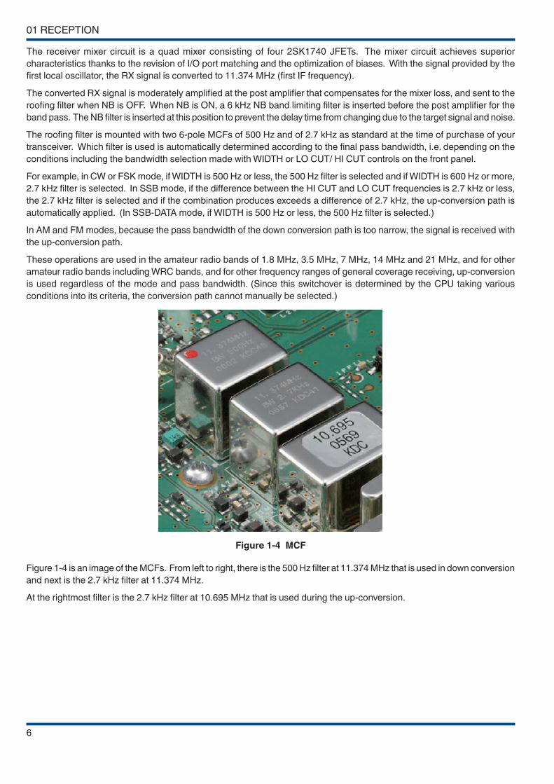
Figure 1-4 MCF
Figure 1-4 is an image of the MCFs. From left to right, there is the 500 Hz filter at 11.374 MHz that is used in down conversion
and next is the 2.7 kHz filter at 11.374 MHz.
At the rightmost filter is the 2.7 kHz filter at 10.695 MHz that is used during the up-conversion.
RECEPTION 01
7
Hints and Tips
● Which type of conversion is used?
• During the transmission:The up-conversion configuration is always used in all modes and bandwidths. During the transmission in SSB mode, the pass bandwidth is determined by the filter settings (digital filter of the DSP) selected in the menu mode. The pass bandwidth of 6 kHz is usually selected for the filter at the analog IF stage during transmission. The local oscillator signal of the last mixer is FM modulated in FM mode and does not affect the pass bandwidth of the filter at the analog IF stage.
• During the reception in AM or FM mode:The up-conversion configuration is always used regardless of the frequency or pass bandwidth settings.
• If WIDTH is switched from 500 Hz to 600 Hz during the reception in the 3.5 MHz band in CW mode:While the down conversion configuration is maintained, the roofing filter is switched from 500 Hz to 2.7 kHz.
• LO CUT is changed to 200 Hz when receiving in the 14 MHz band in SSB mode with LO CUT 300 Hz and HI CUT 3000 Hz:Because the final pass bandwidth exceeds 2.7 kHz, the operation is switched from down-conversion to up-conversion configuration.
• During the reception in the 50 MHz band in SSB mode with LO CUT 300 Hz and HI CUT 2700 Hz:The up-conversion configuration is used. Though the pass bandwidth of the roofing filter is 15 kHz, the 2.7 kHz filter is selected at the second IF of 10.695 MHz.
Table 1-1 Combination of Filters at Conversion
Conversion Type
Analog IF filterFrequency Setting
ConditionsSetting Example
FrequencyPass
Bandwidth
Down conversion (in 1.8 MHz, 3.5 MHz, 7 MHz, 14 MHz and 21 MHz bands and if BW is no more than 2700 Hz)
11.374 MHz (first IF)
500 HzBW is no more than
500 Hz7.005 MHz/ CW WIDTH:
250 Hz
2.7 kHzBW is between 550
Hz and 2700 Hz14.175 MHz/ USB
LO: 100 Hz, HI: 2800 Hz
Up-conversion (in other than above conditions)
10.695 MHz (second IF)
2.7 kHzBW is no more than
2700 Hz28.250 MHz/ USB
LO: 100 Hz, HI: 2800 Hz
6 kHz
SSB BW is between 2750 Hz and 5000
Hz/AM HI CUT between 2.5 kHz and
3 kHz
3.560 MHz/ LSB LO: 50 Hz, HI: 3000 Hz
15 kHzAM HI CUT is
between 4 kHz and 5 kHz/ FM
50.550 MHz/ AM LO: 100 Hz, HI: 4000 Hz
Hints and Tips
● Is KENWOOD’ s AM bandwidth narrow?
The AM passband width is indicated as 5 kHz for HI CUT, and there were questions asking if this can be widened further. The frequency displayed here is the frequency of the audio bandwidth after demodulation. At the IF stage, therefore, the passband is twice as wide at the upper and lower bands, and the IF passband width is indicated as 10 kHz. Also, the filter bandwidth for HI CUT is variable at the IF stage, while that for LO CUT is variable at the audio stage. In the FM mode, the filter bandwidth for both HI CUT and LO CUT is variable at the audio stage.
01 RECEPTION
8
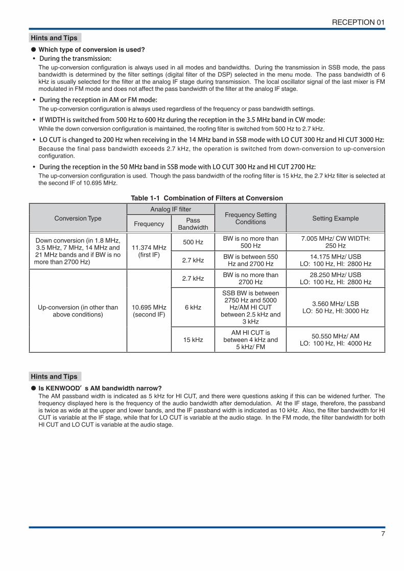
Following is a graph that provides the comparison between the performances of roofing filters.
Figure 1-5 Comparison of Bandpass Characteristics of MCFs
Figure 1-5 compares the band pass characteristics of a roofing filter of center frequency 73 MHz (gray line); and the roofing
filters of the center frequency 11.374 MHz with bandwidth of 500 Hz (blue line) and with bandwidth of 2.7 kHz (orange line)
that are both employed by the TS-590S.
Because the center frequency of the filters differ, graphs are overlapped at the center frequency. The frequency indicated
as 0 kHz at the center of the Frequency [kHz] axis is the receive frequency.
It is apparent that when down conversion is active, large attenuation is achieved at frequencies other than the target signal.
It may be difficult to understand from the figure but for a filter with a bandwidth of 500 Hz, the attenuation is approximately
70 dB and 40 dB when the frequency is detuned 1 kHz and 0.5 kHz respectively from the center frequency. Only the down
conversion configuration can use filters with this kind of characteristic.
Figure 1-6 Comparison of Dynamic Range Characteristics

RECEPTION 01
9
Figure 1-6 shows the measurements for the third-order dynamic range characteristics of TS-590SG with the distance from
the interfering signal altered. As a comparison, the results for an existing model, TS-480HX/SAT (up-conversion, 500 MHz,
built-in CW filter), are displayed side by side with the readings for TS-590S (*extracted from the QST magazine 2011 May
issue of product review; reprinted with permission of ARRL).
The third-order dynamic range characteristics of the TS-590SG are almost flat up to 2 kHz. The intercept point calculated
from these readings is +33 dBm.
Measurement Conditions:
Receive Frequency
14.200 MHz
Mode CW
Pass bandwidth 500 Hz
PRE AMP OFF
The abscissa axis shows the distance from the interfering signal. For example, it represents that at the point of 10 kHz the
receive frequency is 14.200 MHz and two interfering signals of 14.210 MHz and 14.220 MHz are given.
The orange line indicates the result of TS-590SG; the ◇ mark indicates the result of TS-590S; and the gray line indicates
the result of TS-480HX/SAT.
The dynamic range of all the products exceeds 105 dB with an interfering signal separation of more than 20 kHz. However,
as the interfering signal approaches the receive signal, the dynamic range of the up-conversion type TS-480HX/SAT, which
does not make use of a roofing filter with a narrow bandwidth, becomes smaller. This is attributable to the deterioration in
the attenuation of the interfering signal due to the wide passband width of the roofing filter.
Meanwhile, difference is observed between the TS-590SG and TS-590S particularly when it is close to the receive signal
at 2 kHz. This is due to influence from the NB filter immediately after the first mixer. On the TS-590SG, the signal passes
through the NB filter when the NB is OFF, enabling the full performance of the roofing filter.
Note: Measurements of the receive frequency and adjacent bands
◆ A different measurement method was adopted, which accounts for the different results between the data of the TS-590S
published in the catalog and in-depth manual and the ARRL measurements. During measurement of the published data
for the TS-590SG, the same method adopted by ARRL is used for measuring the third-order dynamic range to prevent
differences from arising as a result of the measurement method Figure 1-6 shows the measurements for the TS-590SG
based on random sampling of the mass-produced items. (Data used in the catalog is obtained based on the prototype.) The
outcome is an example, and does not warrant the performance of the product.
01 RECEPTION
10
1.3 Up-Conversion
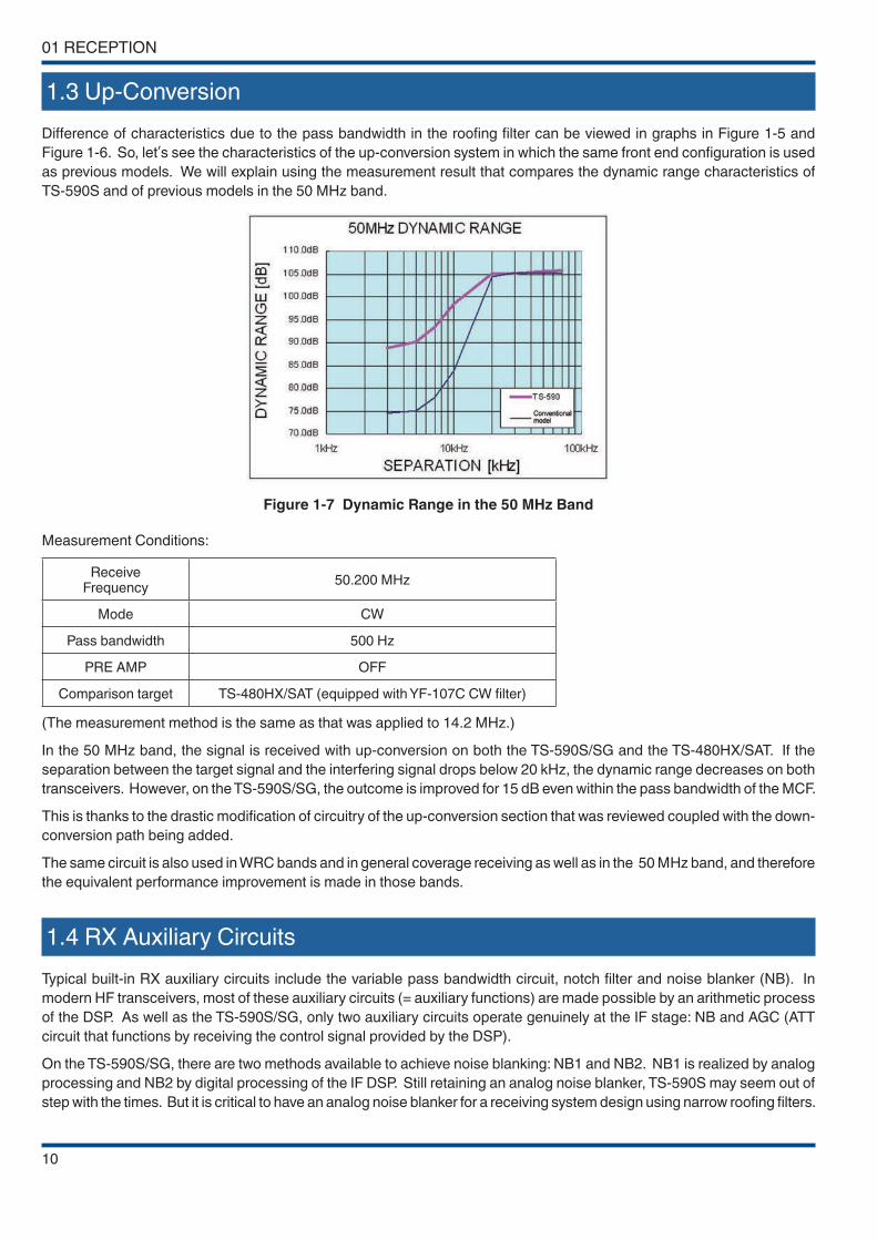
Difference of characteristics due to the pass bandwidth in the roofing filter can be viewed in graphs in Figure 1-5 and
Figure 1-6. So, let’s see the characteristics of the up-conversion system in which the same front end configuration is used
as previous models. We will explain using the measurement result that compares the dynamic range characteristics of
TS-590S and of previous models in the 50 MHz band.
Figure 1-7 Dynamic Range in the 50 MHz Band
Measurement Conditions:
Receive Frequency
50.200 MHz
Mode CW
Pass bandwidth 500 Hz
PRE AMP OFF
Comparison target TS-480HX/SAT (equipped with YF-107C CW filter)
(The measurement method is the same as that was applied to 14.2 MHz.)
In the 50 MHz band, the signal is received with up-conversion on both the TS-590S/SG and the TS-480HX/SAT. If the
separation between the target signal and the interfering signal drops below 20 kHz, the dynamic range decreases on both
transceivers. However, on the TS-590S/SG, the outcome is improved for 15 dB even within the pass bandwidth of the MCF.
This is thanks to the drastic modification of circuitry of the up-conversion section that was reviewed coupled with the down-
conversion path being added.
The same circuit is also used in WRC bands and in general coverage receiving as well as in the 50 MHz band, and therefore
the equivalent performance improvement is made in those bands.
1.4 RX Auxiliary Circuits
Typical built-in RX auxiliary circuits include the variable pass bandwidth circuit, notch filter and noise blanker (NB). In
modern HF transceivers, most of these auxiliary circuits (= auxiliary functions) are made possible by an arithmetic process
of the DSP. As well as the TS-590S/SG, only two auxiliary circuits operate genuinely at the IF stage: NB and AGC (ATT
circuit that functions by receiving the control signal provided by the DSP).
On the TS-590S/SG, there are two methods available to achieve noise blanking: NB1 and NB2. NB1 is realized by analog
processing and NB2 by digital processing of the IF DSP. Still retaining an analog noise blanker, TS-590S may seem out of
step with the times. But it is critical to have an analog noise blanker for a receiving system design using narrow roofing filters.
RECEPTION 01
11
Noise is typically pulse-shaped and when the noise passes a narrow filter, the pulse waveform is changed to have a wider
(longer) pulse width.
Within the DSP, the processing block of the noise blanker is placed in a stage earlier than the filter block that determines
the final pass bandwidth. Thus, even if the final pass bandwidth is narrowed, the blanking operation can work properly,
free of the influence of the narrowed bandwidth.
However, roofing filters are located far earlier than the DSP, in the later stage of the first mixer. As a result, in the event the
bandwidth of the roofing filter becomes as narrow as 500 Hz, the pulse width becomes wider and a conventional digital
noise blanker would not deliver a sufficient blanking effect.
This is the exact case while down conversion is active on the TS-590S/SG and a digital noise blanker alone may not produce
a great enough effect. That is the reason we have placed a filter of pass bandwidth 6 kHz right after the first mixer. The
filter deters the transformation of the pulse shape and prevents false operation of the noise blanker due to adjacent signals
while sending the noise signals to the analog noise blanker.
During the up-conversion, the noise signal is derived from the second IF stage and delivered to the noise blanker circuit
as in previous models.
For the differences in operation for NB1 and NB2, refer to “Hints and Tips” in 04 DSP 4.6.2 “Noise Blanker NB2 (IF
Processing)”.
Hints and Tips
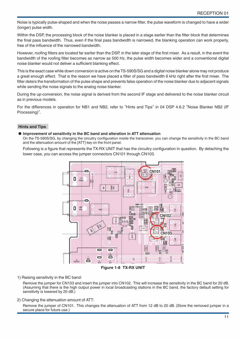
● Improvement of sensitivity in the BC band and alteration in ATT attenuation
On the TS-590S/SG, by changing the circuitry configuration inside the transceiver, you can change the sensitivity in the BC band and the attenuation amount of the [ATT] key on the front panel.
Following is a figure that represents the TX-RX UNIT that has the circuitry configuration in question. By detaching the
lower case, you can access the jumper connectors CN101 through CN103.
Figure 1-8 TX-RX UNIT
1) Raising sensitivity in the BC band:
Remove the jumper for CN103 and insert the jumper into CN102. This will increase the sensitivity in the BC band for 20 dB. (Assuming that there is the high output power in local broadcasting stations in the BC band, the factory default setting for sensitivity is lowered by 20 dB.)
2) Changing the attenuation amount of ATT:
Remove the jumper of CN101. This changes the attenuation of ATT from 12 dB to 20 dB. (Store the removed jumper in a secure place for future use.)
01 RECEPTION
12
Hints and Tips
● The output level of the headphone jack is too high?
The TS-590S is designed based on connection with a headphone with an impedance of 8 Ω. Therefore, if you use a headphone with impedance higher than 8 Ω, you will experience the following symptoms.
• The volume level is too high overall.• Even if AF Volume is turned down, a hissing residual noise is audible.
If you experience these symptoms, use a set of headphones with impedance close to 8 Ω.
The TS-590SG lowers the impedance at the headphone jack to reduce these kinds of symptoms when a high impedance headphone is used. This will reduce the hissing noise by approximately 8 dB compared to TS-590S when the impedance of the headphone is 32 Ω . In this case, increase the AF VR slightly to adjust to the same volume as TS-590S.
Hints and Tips
● Antenna output connector
In recent years, spectrum scope is realized externally by combining receivers of the direct mixer type or digital conversion type, which are collectively referred to as SDR, with PCs and applications, and connecting with HF transceivers. Signals are generally output to an external receiver from the IF output terminal of the HF transceiver. However, in the case of the TS-590S, the IF output function cannot be added straightforwardly as there are multiple IF frequencies. For this reason, an “antenna output connector” is introduced on the TS-590SG to obtain signals for the external receiver.
This feature was also introduced on the existing TS-870S in anticipation of the connection of a receiver as a sub-operator in a contest.
In the actual circuit, signals from the antenna are branched by the built-in splitter circuit and fed to both the internal and external receivers. As the splitter circuit may cause a loss of a few decibels in principle, it can be set to ON or OFF on the panel.
KENWOOD does not have any receiver or application that can be combined. You can refer to related magazine articles for the relevant information. For some applications, the center frequency of the spectrum scope is variable in tandem with the receiving frequency of the transceiver, so you can make use of it in the same way as an IF output terminal.
Also, this feature shares the same connector (RCA terminal) with the DRV output function. You can choose which one to use from the menu.

13
02 TRANSMISSION
2.1 KENWOOD Traditional Transmitting Circuitry
The tradition of high quality audio technology that users rely on KENWOOD to deliver is produced by combining analog
and digital technologies that KENWOOD has nurtured thus far. The DSP controls modulation and determines the sound
quality and analog circuits convey and amplify the signal cleanly.
2.1.1 IF Circuits
The first IF transmit signal that is processed by the DSP and output at 24 kHz from the DA converter is converted to 10.695
MHz in a dedicated IC for the mixer. The second IF signal at 10.695 MHz passes an IF filter of 6 kHz bandwidth at which
undesired frequency components outside the pass bandwidth are attenuated before the signal is amplified. Next, the signal
goes through the gain control circuit that corrects the differences in gain from band to band, and the signal enters the mixer
that is commonly used in TX and RX, and is converted to the third IF of 73.095 MHz. The signal passes through the gain
control circuit that adjusts the signal to the necessary gain level to output the specified power level. After the signal passes
the filter that eliminates spurious components, the power is controlled by an ALC circuit to prevent it from exceeding a certain
level before the signal enters the mixer circuit that converts it to the desired transmit frequency. Also, delicate control is
done, such as stopping the operation of the amplifier while the key is not depressed in CW mode. The signal converted
to the desired transmit frequency passes the BPF for removing spurious signals to prevent from generating interference
outside the transmit bandwidth, and is amplified to a prescribed level before being sent to the final circuit. The drive signal
produced here can be extracted from the DRV terminal. (While the output from DRV is selected.)
In the SSB mode, control is performed by the ALC circuit for the peak envelope power to reach the predetermined setting.
To prevent distortion of the wave to be transmitted when there is a large input, the output level is restricted through DSP by
a AGC upon exceeding a certain level. This prevents any distortion from occurring in the analog circuit after IF. It helps to
prevent distortion as well as splatter from occurring even in the event of a loud sound level. With such meticulous attention
paid to control the level, a high-quality transmit signal with low noise can be acquired.
2.1.2 ALC Circuit
Adopting an ALC control system developed for use on the TS-990S, the TS-590SG is able to send out properly-controlled
signals even at the initial rise of the SSB transmission signal.
2.1.3 FET Final Circuit
The final amplifier is a push-pull amplifier using two pieces of RD100HHF1 MOSFET from Mitsubishi Electric Semiconductor
(Pch 176.5 W). The drive amplifier uses an RD16HHF1 MOSFET and the pre-drive amplifier uses an RD06HHF1 MOSFET,
despite being 13.8 V final circuits, the amplifiers are able to amplify the signal reasonably in a stable and continuous manner
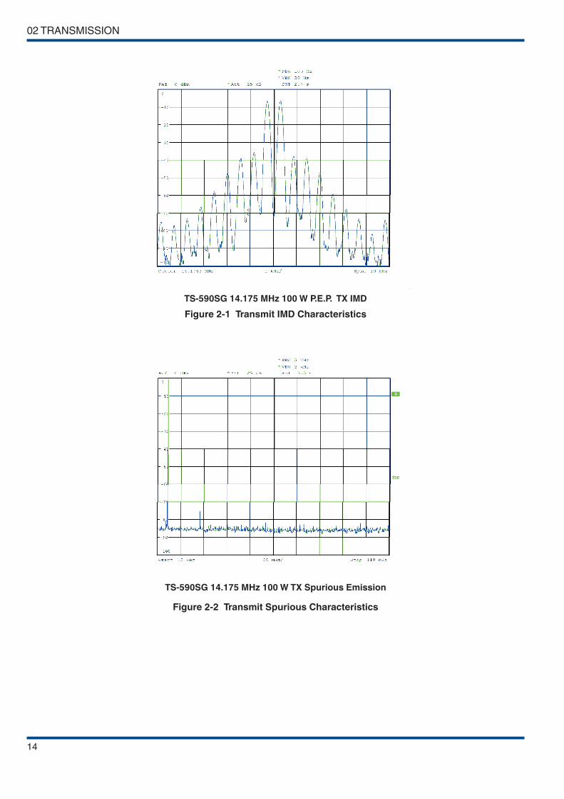
with low distortion. Figure 2-1 shows the graph of IMD characteristics and Figure 2-2 shows the graph of harmonic spurious
characteristics. Superior distortion characteristics and clean signals are acquired in this way.
02 TRANSMISSION
14
TS-590SG 14.175 MHz 100 W P.E.P. TX IMD
Figure 2-1 Transmit IMD Characteristics
TS-590SG 14.175 MHz 100 W TX Spurious Emission
Figure 2-2 Transmit Spurious Characteristics
TRANSMISSION 02
15
2.2 High-speed Relay-controlled Antenna Tuner
TS-590S/SG has a built-in high-speed relay-controlled antenna tuner that was first employed in the TS-570. In contrast to
the variable capacitor type antenna tuner, it employs a small and lightweight relay to achieve a sufficient matching range
and a fast tuning operation with digital control. The control speed has been further accelerated over previous models.
When you return to a previously used operating band or frequency, the antenna tuner easily and quickly re-tunes.
2.3 Linear Amplifier Control
When connecting a linear amplifier, control it using the semiconductor switch or (mechanical) relay that is built into the
transceiver. The relay comes with floating make/break/common contacts, which is suited for the control of linear amplifiers
that do not support full break-in. Meanwhile, the semiconductor switch is suited for the control of linear amplifiers that
support full break-in, and enables more silent switch between sending and receiving than the relay.
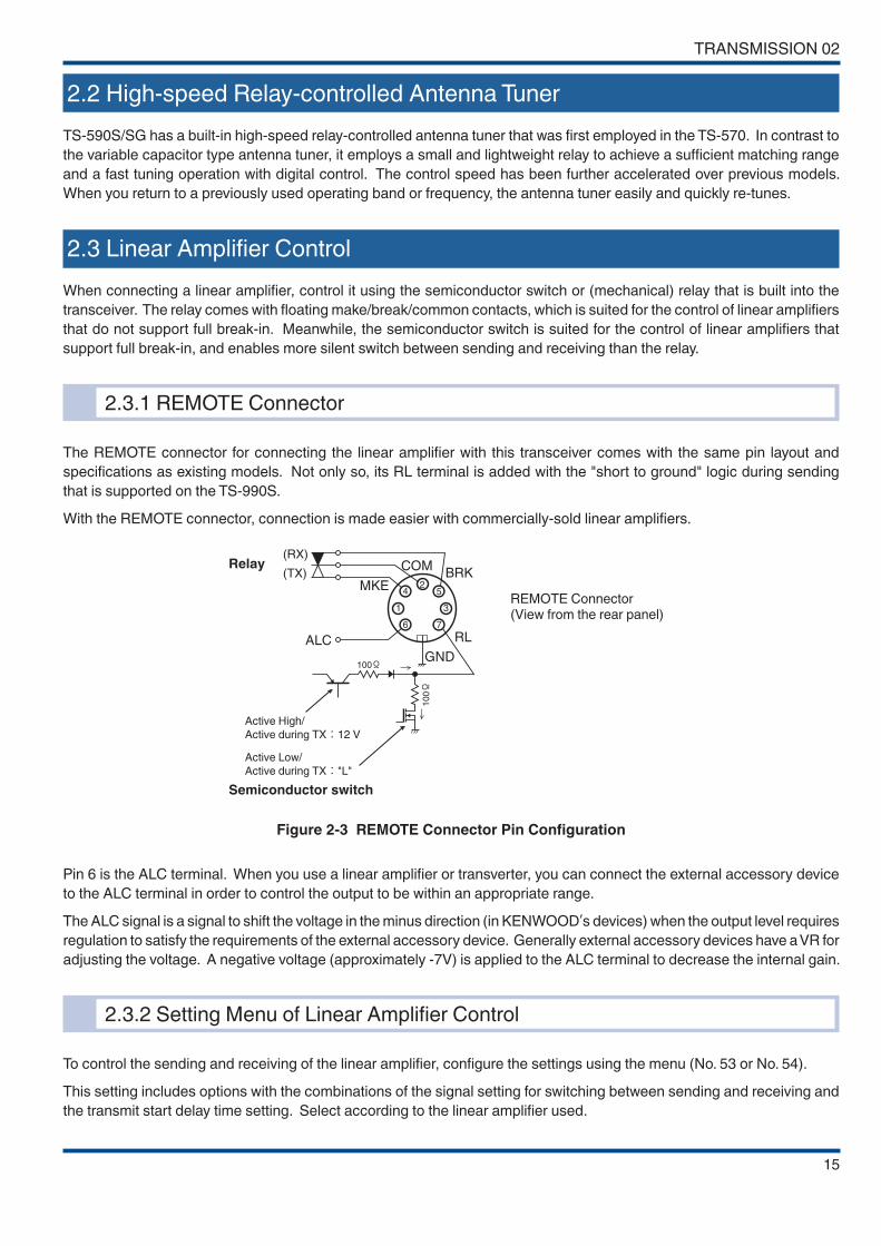
2.3.1 REMOTE Connector
The REMOTE connector for connecting the linear amplifier with this transceiver comes with the same pin layout and
specifications as existing models. Not only so, its RL terminal is added with the "short to ground" logic during sending
that is supported on the TS-990S.
With the REMOTE connector, connection is made easier with commercially-sold linear amplifiers.
24
1
6 7
3
5
ALC
GND
(RX)
(TX)COM
BRK
RL
MKE
100Ω
10
0Ω
Relay
Active High/
Active during TX:12 V
Active Low/
Active during TX:"L"
Semiconductor switch
REMOTE Connector(View from the rear panel)
Figure 2-3 REMOTE Connector Pin Configuration
Pin 6 is the ALC terminal. When you use a linear amplifier or transverter, you can connect the external accessory device
to the ALC terminal in order to control the output to be within an appropriate range.
The ALC signal is a signal to shift the voltage in the minus direction (in KENWOOD’s devices) when the output level requires
regulation to satisfy the requirements of the external accessory device. Generally external accessory devices have a VR for
adjusting the voltage. A negative voltage (approximately -7V) is applied to the ALC terminal to decrease the internal gain.
2.3.2 Setting Menu of Linear Amplifier Control
To control the sending and receiving of the linear amplifier, configure the settings using the menu (No. 53 or No. 54).
This setting includes options with the combinations of the signal setting for switching between sending and receiving and
the transmit start delay time setting. Select according to the linear amplifier used.
02 TRANSMISSION
16
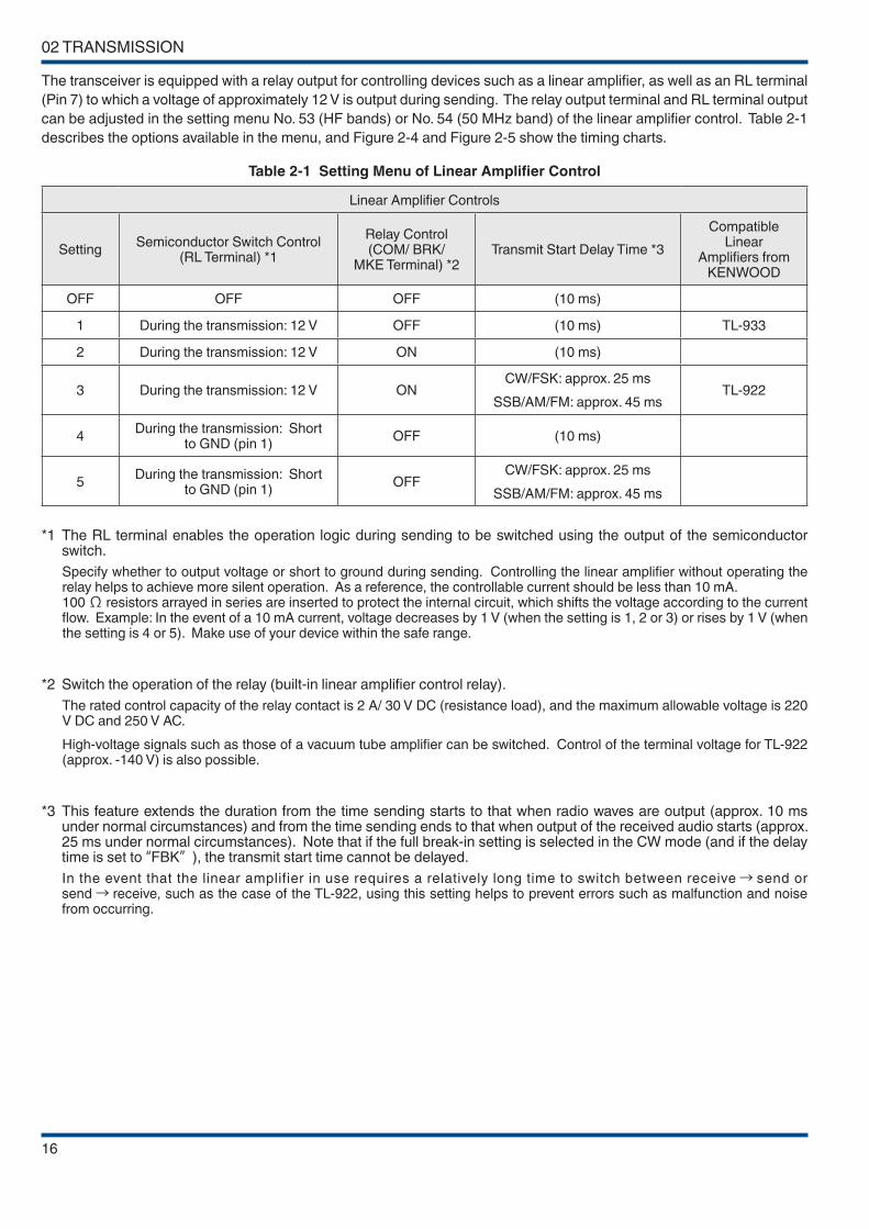
The transceiver is equipped with a relay output for controlling devices such as a linear amplifier, as well as an RL terminal
(Pin 7) to which a voltage of approximately 12 V is output during sending. The relay output terminal and RL terminal output
can be adjusted in the setting menu No. 53 (HF bands) or No. 54 (50 MHz band) of the linear amplifier control. Table 2-1
describes the options available in the menu, and Figure 2-4 and Figure 2-5 show the timing charts.
Table 2-1 Setting Menu of Linear Amplifier Control
Linear Amplifier Controls
SettingSemiconductor Switch Control
(RL Terminal) *1
Relay Control (COM/ BRK/
MKE Terminal) *2Transmit Start Delay Time *3
Compatible Linear
Amplifiers from KENWOOD
OFF OFF OFF (10 ms)
1 During the transmission: 12 V OFF (10 ms) TL-933
2 During the transmission: 12 V ON (10 ms)
3 During the transmission: 12 V ONCW/FSK: approx. 25 ms
SSB/AM/FM: approx. 45 msTL-922
4During the transmission: Short
to GND (pin 1) OFF (10 ms)
5During the transmission: Short
to GND (pin 1)OFF
CW/FSK: approx. 25 ms
SSB/AM/FM: approx. 45 ms
*1 The RL terminal enables the operation logic during sending to be switched using the output of the semiconductor switch.
Specify whether to output voltage or short to ground during sending. Controlling the linear amplifier without operating the relay helps to achieve more silent operation. As a reference, the controllable current should be less than 10 mA. 100 Ω resistors arrayed in series are inserted to protect the internal circuit, which shifts the voltage according to the current flow. Example: In the event of a 10 mA current, voltage decreases by 1 V (when the setting is 1, 2 or 3) or rises by 1 V (when the setting is 4 or 5). Make use of your device within the safe range.
*2 Switch the operation of the relay (built-in linear amplifier control relay).
The rated control capacity of the relay contact is 2 A/ 30 V DC (resistance load), and the maximum allowable voltage is 220 V DC and 250 V AC.
High-voltage signals such as those of a vacuum tube amplifier can be switched. Control of the terminal voltage for TL-922 (approx. -140 V) is also possible.
*3 This feature extends the duration from the time sending starts to that when radio waves are output (approx. 10 ms under normal circumstances) and from the time sending ends to that when output of the received audio starts (approx. 25 ms under normal circumstances). Note that if the full break-in setting is selected in the CW mode (and if the delay time is set to “FBK” ), the transmit start time cannot be delayed.
In the event that the linear amplifier in use requires a relatively long time to switch between receive→ send or send→ receive, such as the case of the TL-922, using this setting helps to prevent errors such as malfunction and noise from occurring.

TRANSMISSION 02
17
Figure 2-4 Timing chart (1, 2 or 4)
Figure 2-5 Timing chart (3 or 5)
For large relays, some time is generally required from the point power is supplied to the time the contact switches. The
duration of chattering is likely to be longer too at the time of switching. In the event that sending is attempted before the
contact switches to the sending end, the SWR level rises until switching is complete. On the TS-590SG, the protective
circuit is activated to lower the transmit output momentarily. In addition, if the sound of the relay switching operation is
loud, this may be picked up by the microphone, and transmit signals may be output by this sound as a result. Loud click
noise may occur if the contact switches to the receiving end after reception starts. Delay time is added when [3] or [5] is
selected as the setting, which helps to prevent such errors from occurring.

02 TRANSMISSION
18
2.3.3 ALC Operation when Connected to an External Device
Figure 2-6 shows the block diagram of the connection with the external device when the ALC signal is input to TS-590SG
from an external device; Figure 2-7 shows the characteristic of the output level variation according to the ALC voltage.
This is a method for controlling the gain of TS-590SG using the ALC voltage output from the external device, which in turn
controls the transmit output of TS-590SG as a result. Operation is the same for both linear amplifiers and transverters.
The gain level in the IF circuit of TS-590SG lowers when there is a drop in the ALC voltage input from the external device.
A decrease in the gain level lowers the transmit output (ANT or DRV output), which in turn controls the output.
Figure 2-6 External ALC Control Block
Figure 2-7 Output Level for External ALC Voltage
Caution: Operation when ALC is applied from an external device
◆ If the MIC gain and CAR level are preset to achieve an optimum level without the deflection of the ALC meter of this
transceiver being subject to the ALC voltage of an external device, ALC will be further applied when there is input of ALC
voltage from an external device, and the deflection of the ALC meter will increase as a result. In this case, turn the [PWR]
knob to decrease the power while monitoring the ALC meter, or set the MIC gain and CAR level again to adjust the deflection
of the ALC meter to an appropriate level.
TRANSMISSION 02
19
2.4 DRV Terminal
The TS-590SG is equipped with a DRV terminal formerly available only on high-end transceivers. It is capable of signal
output prior to amplification to 100 W at the final unit.
The output level of the signal from this terminal is too low to be transmitted as is, but by connecting a high-gain linear
amplifier, the signal can be used for operation in the 135 kHz or 475 kHz band, or for operation with a transverter.
The output level of the DRV terminal is about 0 dBm (1 mW), and can be decreased to around 1/20 depending on the
setting of the transmit power. To reduce the output level further, you can adjust the transmit power also by the carrier level
in CW, FSK and AM modes or by the microphone gain or processor output level in SSB mode.
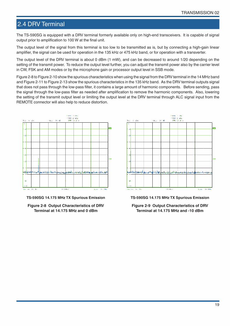
Figure 2-8 to Figure 2-10 show the spurious characteristics when using the signal from the DRV terminal in the 14 MHz band
and Figure 2-11 to Figure 2-13 show the spurious characteristics in the 135 kHz band. As the DRV terminal outputs signal
that does not pass through the low-pass filter, it contains a large amount of harmonic components. Before sending, pass
the signal through the low-pass filter as needed after amplification to remove the harmonic components. Also, lowering
the setting of the transmit output level or limiting the output level at the DRV terminal through ALC signal input from the
REMOTE connector will also help to reduce distortion.
TS-590SG 14.175 MHz TX Spurious Emission
Figure 2-8 Output Characteristics of DRV
Terminal at 14.175 MHz and 0 dBm
TS-590SG 14.175 MHz TX Spurious Emission
Figure 2-9 Output Characteristics of DRV
Terminal at 14.175 MHz and -10 dBm

02 TRANSMISSION
20
TS-590SG 14.175 MHz TX Spurious Emission
Figure 2-10 Output Characteristics of DRV
Terminal at 14.175 MHz and -20 dBm
TS-590SG 136 kHz TX Spurious Emission
Figure 2-11 Output Characteristics of
DRV Terminal at 136 kHz and 0 dBm
TS-590SG 136 kHz TX Spurious Emission
Figure 2-12 Output Characteristics of DRV
Terminal at 136 kHz and -10 dBm
TS-590SG 136 kHz TX Spurious Emission
Figure 2-13 Output Characteristics of DRV
Terminal at 136 kHz and -20 dBm
21
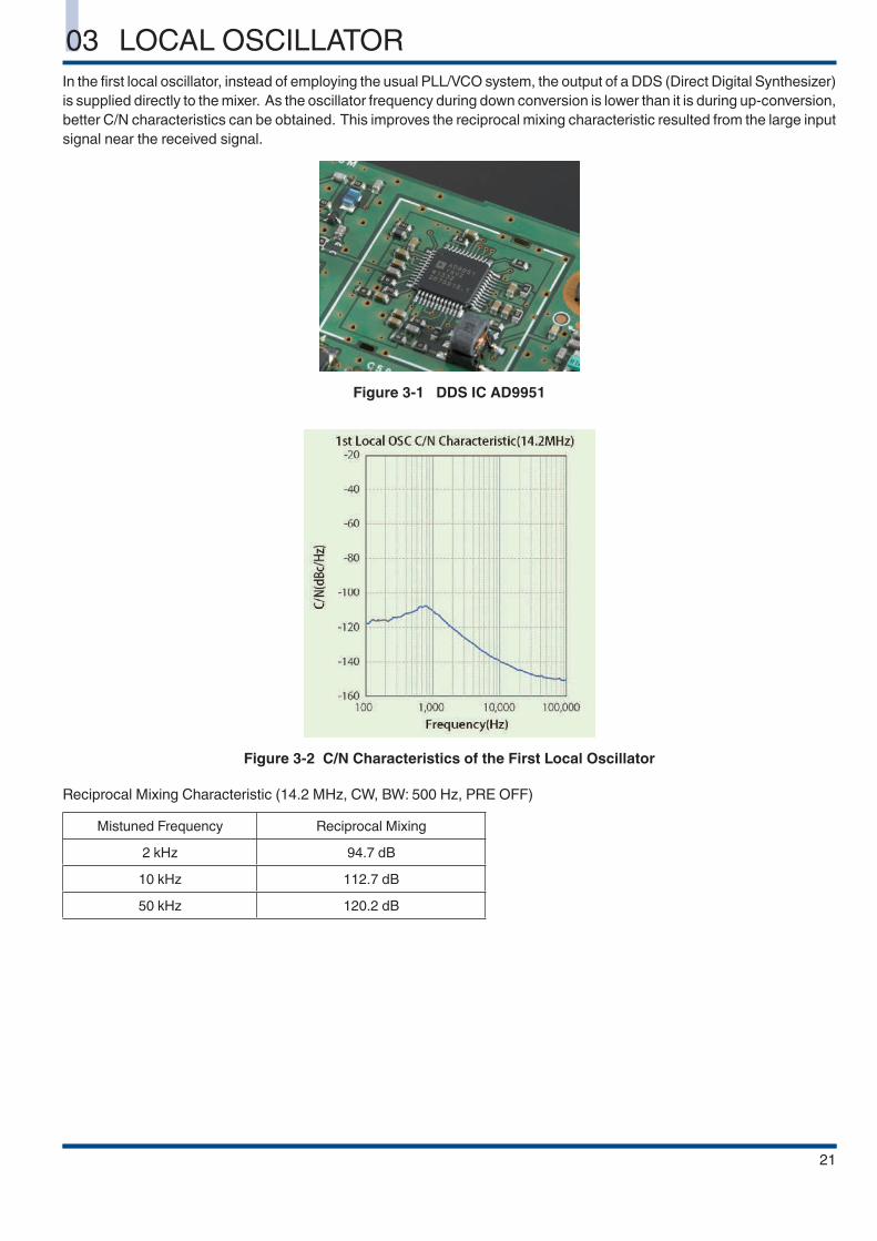
In the first local oscillator, instead of employing the usual PLL/VCO system, the output of a DDS (Direct Digital Synthesizer)
is supplied directly to the mixer. As the oscillator frequency during down conversion is lower than it is during up-conversion,
better C/N characteristics can be obtained. This improves the reciprocal mixing characteristic resulted from the large input
signal near the received signal.
Figure 3-1 DDS IC AD9951
Figure 3-2 C/N Characteristics of the First Local Oscillator
Reciprocal Mixing Characteristic (14.2 MHz, CW, BW: 500 Hz, PRE OFF)
Mistuned Frequency Reciprocal Mixing
2 kHz 94.7 dB
10 kHz 112.7 dB
50 kHz 120.2 dB
03 LOCAL OSCILLATOR
22
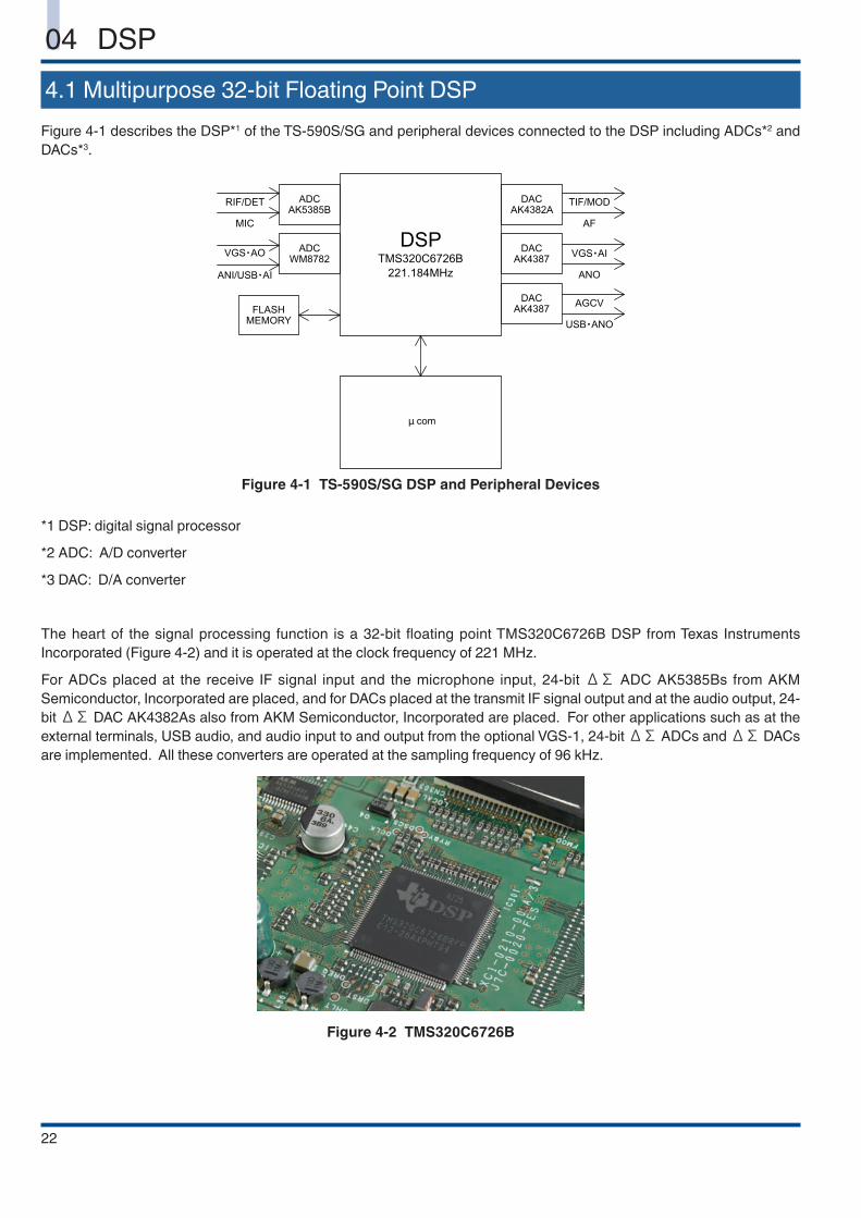
4.1 Multipurpose 32-bit Floating Point DSP
Figure 4-1 describes the DSP*1 of the TS-590S/SG and peripheral devices connected to the DSP including ADCs*2 and
DACs*3.
Figure 4-1 TS-590S/SG DSP and Peripheral Devices
*1 DSP: digital signal processor
*2 ADC: A/D converter
*3 DAC: D/A converter
The heart of the signal processing function is a 32-bit floating point TMS320C6726B DSP from Texas Instruments
Incorporated (Figure 4-2) and it is operated at the clock frequency of 221 MHz.
For ADCs placed at the receive IF signal input and the microphone input, 24-bit ΔΣ ADC AK5385Bs from AKM
Semiconductor, Incorporated are placed, and for DACs placed at the transmit IF signal output and at the audio output, 24-
bit ΔΣ DAC AK4382As also from AKM Semiconductor, Incorporated are placed. For other applications such as at the
external terminals, USB audio, and audio input to and output from the optional VGS-1, 24-bit ΔΣ ADCs and ΔΣ DACs
are implemented. All these converters are operated at the sampling frequency of 96 kHz.
Figure 4-2 TMS320C6726B
04 DSP
DSP 04
23
As for ADCs and DACs, the best combination of models are selected to suit the type of signal processed, especially for the
IF input section, high-performance ADCs designed for high-end audio with dynamic range of 114 dB are used.
Both the ADCs and DACs have two analog input/output channels per device and the DSP has four input channels and six
output channels of signals.
As indicated above, the DSP processes many signals concurrently. This delivers a wide variety of benefits including the
capability to independently set volume levels of speakers, signal levels from external terminals and USB audio, and to
trigger the VOX circuit through the microphone and the external terminal at the same time.
However, handling so many signals simultaneously puts a heavy load on the 32-bit floating point DSP, though it operates
at the clock frequency of 221 MHz. The DSP needs to be able to handle many different signals, while performing not only
basic functions including IF-AGC, digital IF filtering, and demodulation, but also more advanced functions such as noise
reduction and manual notch filtering. To achieve this goal, we have introduced a real-time OS to the DSP of the TS-590S/
SG and also paid careful attention to the software configuration to help deliver utmost performance from the OS.
The DSP of TS-590S/SG realizes a variety of functions with its signal processing software that is optimized to fully bring
out the performance of the high-performance hardware of the transceiver.
In the following sections, we will explain the functions made possible with the innovative DSP signal processing technologies.
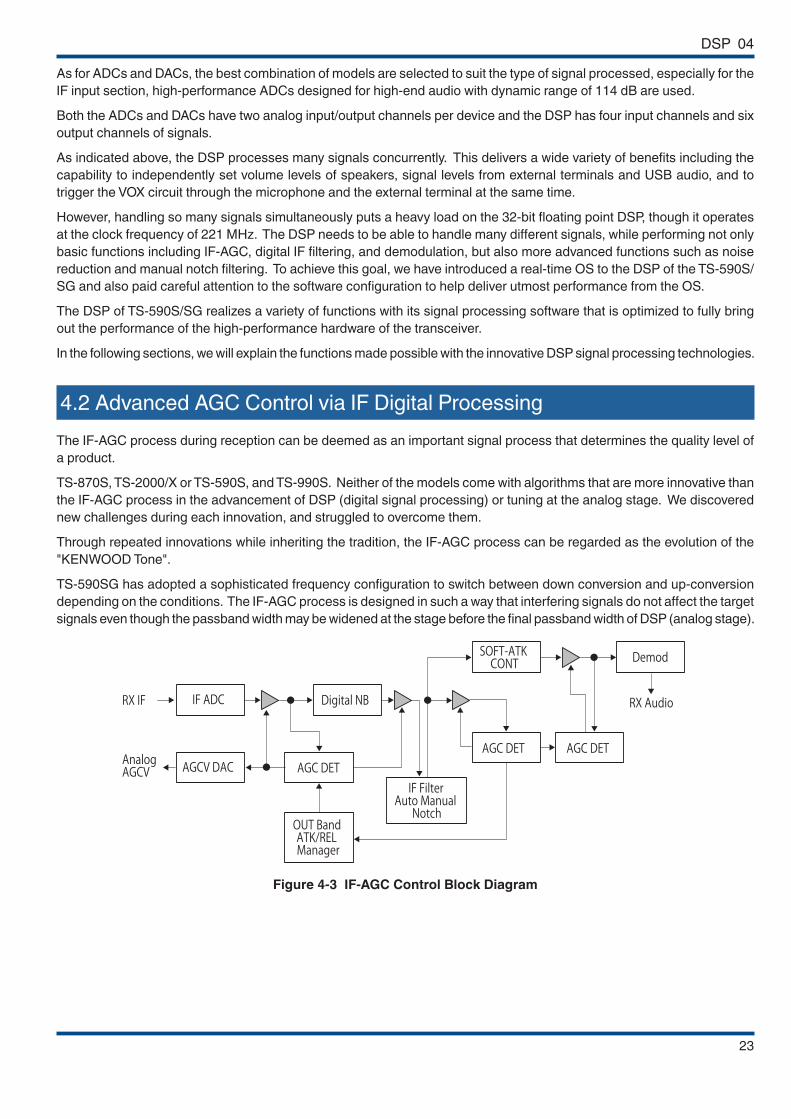
4.2 Advanced AGC Control via IF Digital Processing
The IF-AGC process during reception can be deemed as an important signal process that determines the quality level of
a product.
TS-870S, TS-2000/X or TS-590S, and TS-990S. Neither of the models come with algorithms that are more innovative than
the IF-AGC process in the advancement of DSP (digital signal processing) or tuning at the analog stage. We discovered
new challenges during each innovation, and struggled to overcome them.
Through repeated innovations while inheriting the tradition, the IF-AGC process can be regarded as the evolution of the
"KENWOOD Tone".
TS-590SG has adopted a sophisticated frequency configuration to switch between down conversion and up-conversion
depending on the conditions. The IF-AGC process is designed in such a way that interfering signals do not affect the target
signals even though the passband width may be widened at the stage before the final passband width of DSP (analog stage).
Figure 4-3 IF-AGC Control Block Diagram
04 DSP
24
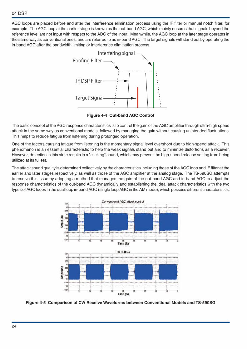
AGC loops are placed before and after the interference elimination process using the IF filter or manual notch filter, for
example. The AGC loop at the earlier stage is known as the out-band AGC, which mainly ensures that signals beyond the
reference level are not input with respect to the ADC of the input. Meanwhile, the AGC loop at the later stage operates in
the same way as conventional ones, and are referred to as in-band AGC. The target signals will stand out by operating the
in-band AGC after the bandwidth limiting or interference elimination process.
Figure 4-4 Out-band AGC Control
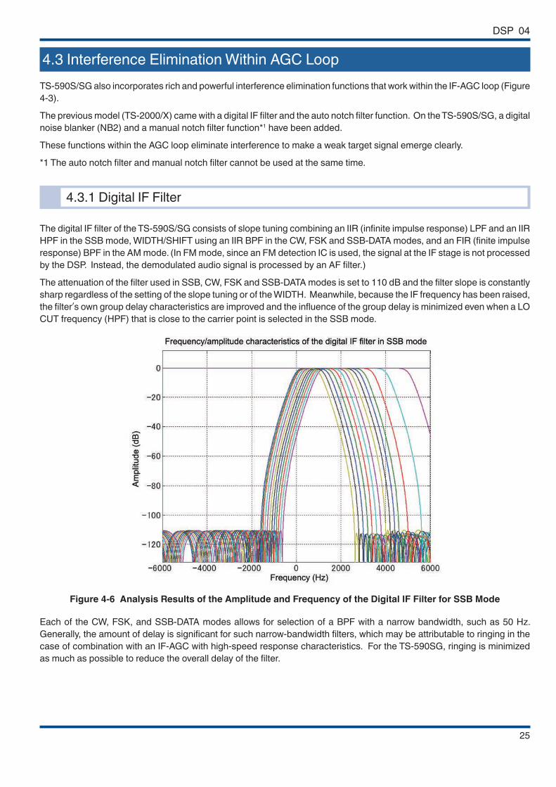
The basic concept of the AGC response characteristics is to control the gain of the AGC amplifier through ultra-high speed
attack in the same way as conventional models, followed by managing the gain without causing unintended fluctuations.
This helps to reduce fatigue from listening during prolonged operation.
One of the factors causing fatigue from listening is the momentary signal level overshoot due to high-speed attack. This
phenomenon is an essential characteristic to help the weak signals stand out and to minimize distortions as a receiver.
However, detection in this state results in a "clicking" sound, which may prevent the high-speed release setting from being
utilized at its fullest.
The attack sound quality is determined collectively by the characteristics including those of the AGC loop and IF filter at the
earlier and later stages respectively, as well as those of the AGC amplifier at the analog stage. The TS-590SG attempts
to resolve this issue by adopting a method that manages the gain of the out-band AGC and in-band AGC to adjust the
response characteristics of the out-band AGC dynamically and establishing the ideal attack characteristics with the two
types of AGC loops in the dual loop in-band AGC (single loop AGC in the AM mode), which possess different characteristics.
Figure 4-5 Comparison of CW Receive Waveforms between Conventional Models and TS-590SG
DSP 04
25
4.3 Interference Elimination Within AGC Loop
TS-590S/SG also incorporates rich and powerful interference elimination functions that work within the IF-AGC loop (Figure
4-3).
The previous model (TS-2000/X) came with a digital IF filter and the auto notch filter function. On the TS-590S/SG, a digital
noise blanker (NB2) and a manual notch filter function*1 have been added.
These functions within the AGC loop eliminate interference to make a weak target signal emerge clearly.
*1 The auto notch filter and manual notch filter cannot be used at the same time.
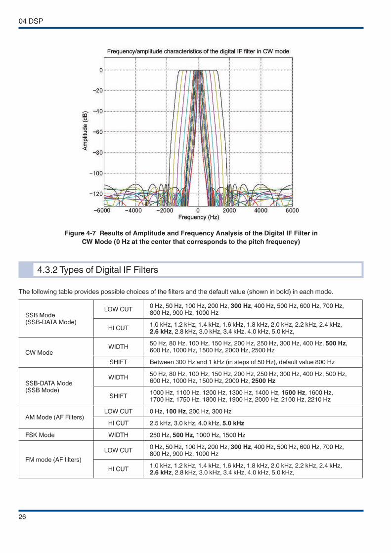
4.3.1 Digital IF Filter
The digital IF filter of the TS-590S/SG consists of slope tuning combining an IIR (infinite impulse response) LPF and an IIR
HPF in the SSB mode, WIDTH/SHIFT using an IIR BPF in the CW, FSK and SSB-DATA modes, and an FIR (finite impulse
response) BPF in the AM mode. (In FM mode, since an FM detection IC is used, the signal at the IF stage is not processed
by the DSP. Instead, the demodulated audio signal is processed by an AF filter.)
The attenuation of the filter used in SSB, CW, FSK and SSB-DATA modes is set to 110 dB and the filter slope is constantly
sharp regardless of the setting of the slope tuning or of the WIDTH. Meanwhile, because the IF frequency has been raised,
the filter’s own group delay characteristics are improved and the influence of the group delay is minimized even when a LO
CUT frequency (HPF) that is close to the carrier point is selected in the SSB mode.
Figure 4-6 Analysis Results of the Amplitude and Frequency of the Digital IF Filter for SSB Mode
Each of the CW, FSK, and SSB-DATA modes allows for selection of a BPF with a narrow bandwidth, such as 50 Hz.
Generally, the amount of delay is significant for such narrow-bandwidth filters, which may be attributable to ringing in the
case of combination with an IF-AGC with high-speed response characteristics. For the TS-590SG, ringing is minimized
as much as possible to reduce the overall delay of the filter.
04 DSP
26
Figure 4-7 Results of Amplitude and Frequency Analysis of the Digital IF Filter in
CW Mode (0 Hz at the center that corresponds to the pitch frequency)
4.3.2 Types of Digital IF Filters
The following table provides possible choices of the filters and the default value (shown in bold) in each mode.
SSB Mode (SSB-DATA Mode)
LOW CUT0 Hz, 50 Hz, 100 Hz, 200 Hz, 300 Hz, 400 Hz, 500 Hz, 600 Hz, 700 Hz, 800 Hz, 900 Hz, 1000 Hz
HI CUT1.0 kHz, 1.2 kHz, 1.4 kHz, 1.6 kHz, 1.8 kHz, 2.0 kHz, 2.2 kHz, 2.4 kHz, 2.6 kHz, 2.8 kHz, 3.0 kHz, 3.4 kHz, 4.0 kHz, 5.0 kHz,
CW ModeWIDTH
50 Hz, 80 Hz, 100 Hz, 150 Hz, 200 Hz, 250 Hz, 300 Hz, 400 Hz, 500 Hz, 600 Hz, 1000 Hz, 1500 Hz, 2000 Hz, 2500 Hz
SHIFT Between 300 Hz and 1 kHz (in steps of 50 Hz), default value 800 Hz
SSB-DATA Mode (SSB Mode)
WIDTH50 Hz, 80 Hz, 100 Hz, 150 Hz, 200 Hz, 250 Hz, 300 Hz, 400 Hz, 500 Hz, 600 Hz, 1000 Hz, 1500 Hz, 2000 Hz, 2500 Hz
SHIFT1000 Hz, 1100 Hz, 1200 Hz, 1300 Hz, 1400 Hz, 1500 Hz, 1600 Hz, 1700 Hz, 1750 Hz, 1800 Hz, 1900 Hz, 2000 Hz, 2100 Hz, 2210 Hz
AM Mode (AF Filters)LOW CUT 0 Hz, 100 Hz, 200 Hz, 300 Hz
HI CUT 2.5 kHz, 3.0 kHz, 4.0 kHz, 5.0 kHz
FSK Mode WIDTH 250 Hz, 500 Hz, 1000 Hz, 1500 Hz
FM mode (AF filters)
LOW CUT0 Hz, 50 Hz, 100 Hz, 200 Hz, 300 Hz, 400 Hz, 500 Hz, 600 Hz, 700 Hz, 800 Hz, 900 Hz, 1000 Hz
HI CUT1.0 kHz, 1.2 kHz, 1.4 kHz, 1.6 kHz, 1.8 kHz, 2.0 kHz, 2.2 kHz, 2.4 kHz, 2.6 kHz, 2.8 kHz, 3.0 kHz, 3.4 kHz, 4.0 kHz, 5.0 kHz,
DSP 04
27
4.3.3 Manual Notch Filter and Auto Notch Filter
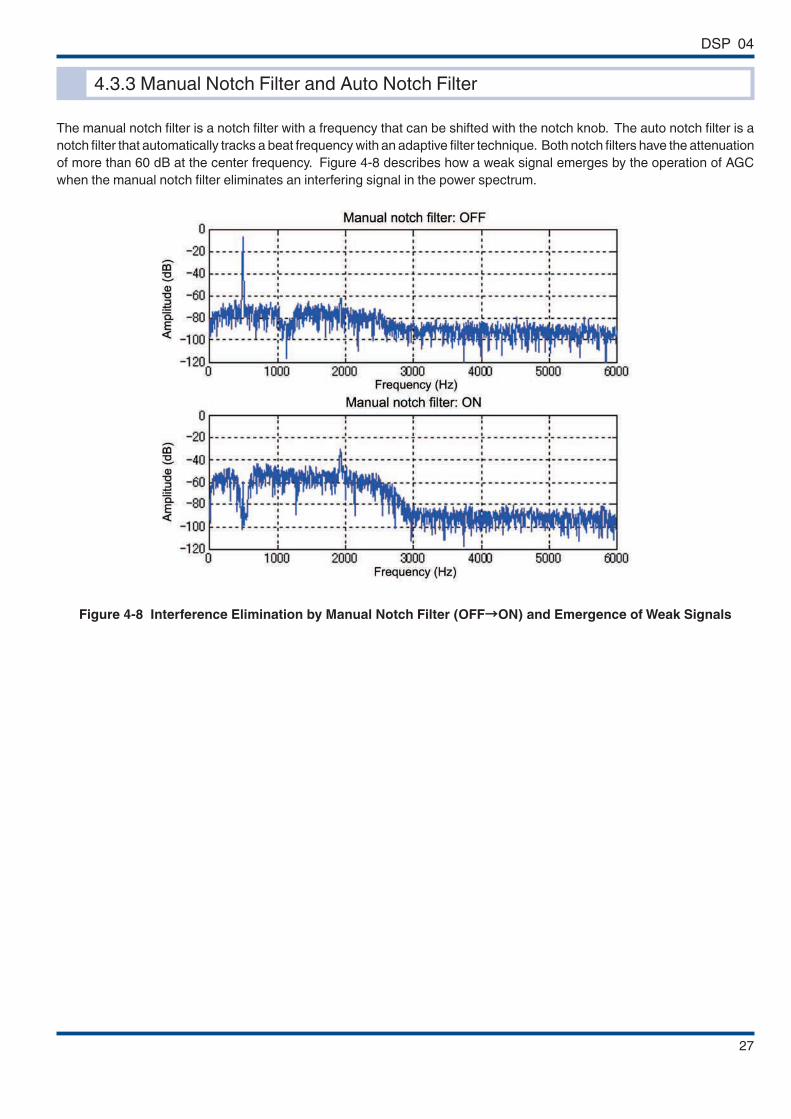
The manual notch filter is a notch filter with a frequency that can be shifted with the notch knob. The auto notch filter is a
notch filter that automatically tracks a beat frequency with an adaptive filter technique. Both notch filters have the attenuation
of more than 60 dB at the center frequency. Figure 4-8 describes how a weak signal emerges by the operation of AGC
when the manual notch filter eliminates an interfering signal in the power spectrum.
Figure 4-8 Interference Elimination by Manual Notch Filter (OFF→ON) and Emergence of Weak Signals
04 DSP
28
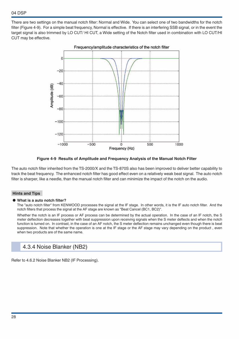
There are two settings on the manual notch filter: Normal and Wide. You can select one of two bandwidths for the notch
filter (Figure 4-9). For a simple beat frequency, Normal is effective. If there is an interfering SSB signal, or in the event the
target signal is also trimmed by LO CUT/ HI CUT, a Wide setting of the Notch filter used in combination with LO CUT/HI
CUT may be effective.
Figure 4-9 Results of Amplitude and Frequency Analysis of the Manual Notch Filter
The auto notch filter inherited from the TS-2000/X and the TS-870S also has been improved to deliver better capability to
track the beat frequency. The enhanced notch filter has good effect even on a relatively weak beat signal. The auto notch
filter is sharper, like a needle, than the manual notch filter and can minimize the impact of the notch on the audio.
Hints and Tips
● What is a auto notch filter?
The "auto notch filter" from KENWOOD processes the signal at the IF stage. In other words, it is the IF auto notch filter. And the notch filters that process the signal at the AF stage are known as "Beat Cancel (BC1, BC2)".
Whether the notch is an IF process or AF process can be determined by the actual operation. In the case of an IF notch, the S meter deflection decreases together with beat suppression upon receiving signals when the S meter deflects and when the notch function is turned on. In contrast, in the case of an AF notch, the S meter deflection remains unchanged even though there is beat suppression. Note that whether the operation is one at the IF stage or the AF stage may vary depending on the product , even when two products are of the same name.
4.3.4 Noise Blanker (NB2)
Refer to 4.6.2 Noise Blanker NB2 (IF Processing).
DSP 04
29
4.4 Demodulation
For the demodulation of the RX signal in SSB, CW, FSK and SSB-DATA modes, we have employed the proven PSN (Phase
Shift Network) design again.
In the previous models (TS-2000/X and TS-870S), the selection of the PSN’s characteristics was interlocked with the
passband setting of the IF filter, and when the passband is narrow, a PSN with a good sideband suppression was selected.
On the other hand, on the TS-590S/SG, the order of the PSN is decreased by tuning the PSN only to the opposite side
band that was not fully removed by the digital IF filter.
In this way, the low frequency range of the PSN stretches out substantially and the poor group delay characteristics in the
lower frequency range, which is a drawback of a PSN, is also improved. As a result, the low range reaches farther with
less attenuation than that reached in the previous models.
In SSB mode, the digital IF filter has a setting of “0 Hz” in LO CUT and this means the cutoff frequency is set to the carrier
point so that the low frequency range can be stretched out maximally. Enjoy distinctly different audio from that of previous
transceivers.
The same demodulation process is used in SSB, CW FSK and SSB-DATA modes, except that the selection of PSN
characteristics and of digital IF filters varies depending on the mode.
In AM mode, an absolute value detection circuit is used for demodulation as in the previous models.
04 DSP
30
4.5 Modulation
Following is how the TX signal is processed. The audio signal captured from the microphone or an external terminal is first
processed by the bandwidth-limiting filter, microphone gain control, speech processor or VOX, and then, in SSB and AM
modes, the signal is modulated and output as an IF signal; in FM mode, a CTCSS tone signal is added.
In CW mode, the waveform of the keying input is shaped and then the signal is multiplied by the modulating carrier to be
transmitted as an IF signal. At the same time, the signal is multiplied by a carrier for monitoring to produce a CW sidetone.
In FSK mode, the keying input is processed by a baseband filter for bandwidth limiting, and then the signal is processed by
frequency modulation with the 24 kHz center frequency to obtain an FSK modulated wave. As in CW mode, for the purpose
of monitoring, the audio center frequency based on the FSK tone frequency setting in the menu mode is processed by
frequency modulation to obtain the monitoring audio.
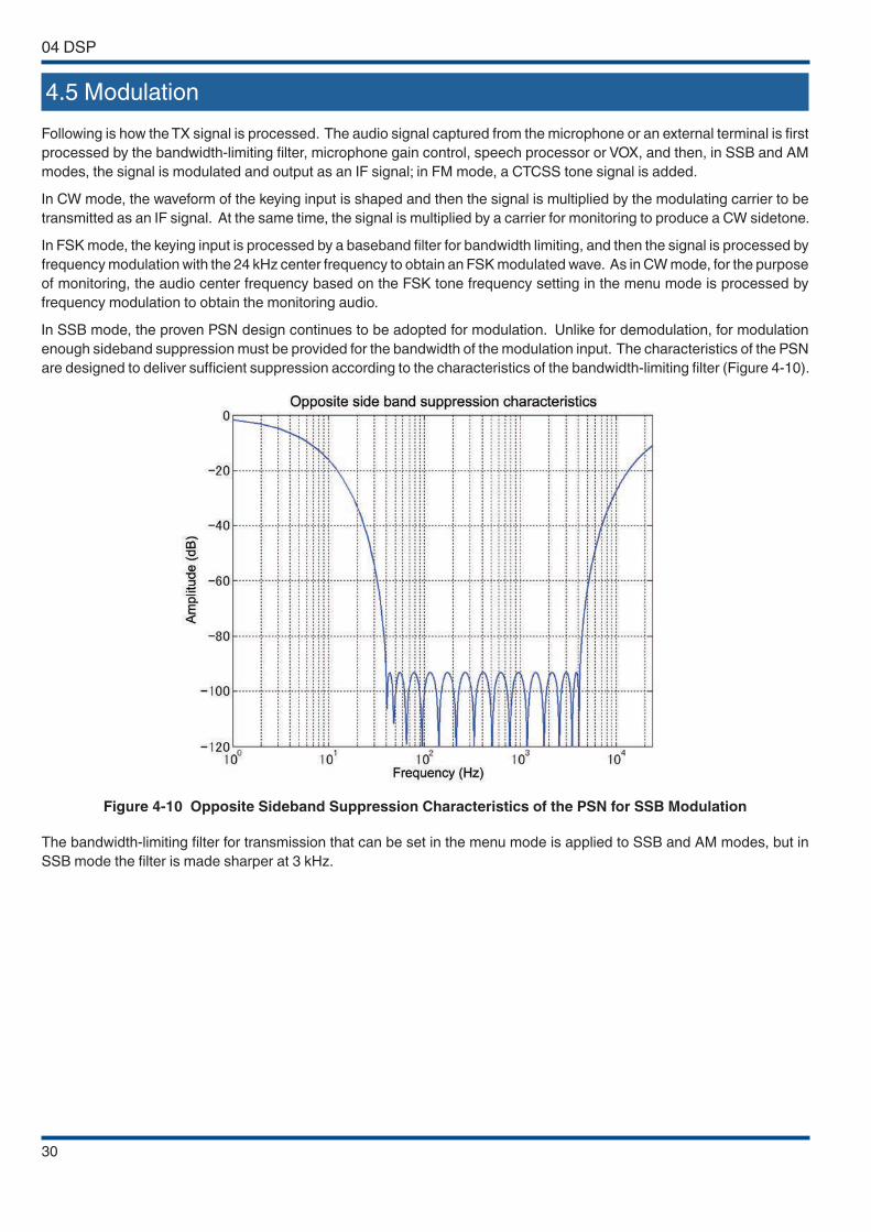
In SSB mode, the proven PSN design continues to be adopted for modulation. Unlike for demodulation, for modulation
enough sideband suppression must be provided for the bandwidth of the modulation input. The characteristics of the PSN
are designed to deliver sufficient suppression according to the characteristics of the bandwidth-limiting filter (Figure 4-10).
Figure 4-10 Opposite Sideband Suppression Characteristics of the PSN for SSB Modulation
The bandwidth-limiting filter for transmission that can be set in the menu mode is applied to SSB and AM modes, but in
SSB mode the filter is made sharper at 3 kHz.
DSP 04
31
4.6 DSP-based Auxiliary Circuits (for RX)
4.6.1 Beat Cancel (AF Processing)
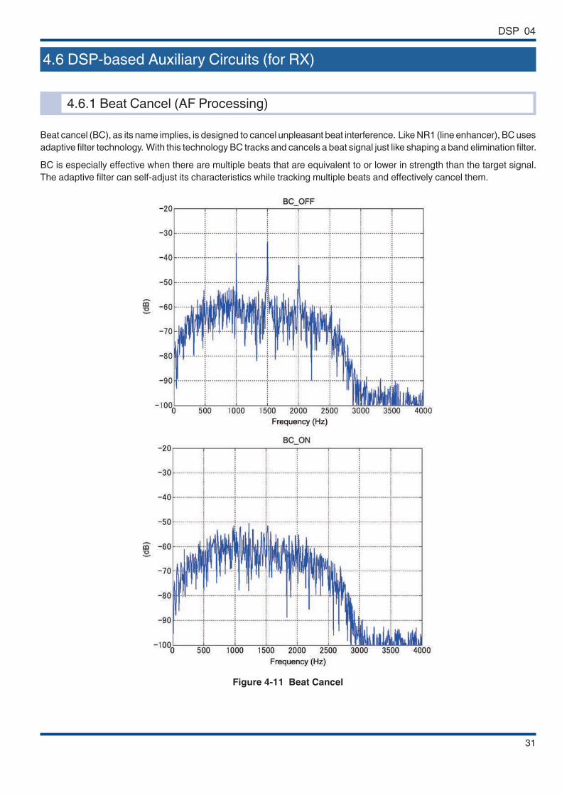
Beat cancel (BC), as its name implies, is designed to cancel unpleasant beat interference. Like NR1 (line enhancer), BC uses
adaptive filter technology. With this technology BC tracks and cancels a beat signal just like shaping a band elimination filter.
BC is especially effective when there are multiple beats that are equivalent to or lower in strength than the target signal.
The adaptive filter can self-adjust its characteristics while tracking multiple beats and effectively cancel them.
Figure 4-11 Beat Cancel

04 DSP
32
Figure 4-11 shows how BC cancels beat signals, as monitored by an FFT analyzer. Notice how multiple beats are clearly
removed by BC.
There are two methods available for beat cancellation: BC1 and BC2. BC1 is tuned to be effective against weak or continuous
beat interference, while BC2 cancels intermittent beats such as a CW signal. Note that since BC is designed to remove
beats, it does not function in CW mode.
BC is a signal process method at the AF stage. Therefore, if there is a beat signal in proximity that is stronger than the
target signal, BC effectively removes the beat interference from the audio output, but in the event the AGC is activated by
the beat signal, the target signal is suppressed when received.
In such an occasion, the auto notch or manual notch filter that works at the IF stage is more effective.
4.6.2 Noise Blanker NB2 (IF Processing)
We explained in the section of RX circuit that TS-590S/SG is equipped with two noise blankers, NB1 and NB2, and that
NB2 is a digital noise blanker based on the DSP. In the following section, we will explain NB2 in detail.
A noise blanker is designed to remove pulse noise at the IF stage to reveal the target signal suppressed by the AGC that
was activated by the pulse noise. In addition to the analog noise blanker (NB1), the TS-590S/SG is equipped with the
digital noise blanker (NB2) newly developed for the TS-590S so that the user can choose a blanker that is more effective
for the type of noise encountered and the RX conditions.
NB2 employs an envelope tracking method, making it effective against noise that defies the tracking of the analog noise
blanker (NB1).
Unlike the analog noise blanker, the procedure of NB2 is not a simple blanking of pulse noises from the target signal. NB2
removes pulse noises by tracking the RX signal level to automatically detect pulses and comparing the level of the pulses
and of the target signal excluding the pulses to attenuate the pulse parts appropriately. Hence, even a long pulse can be
processed without seriously degrading the target signal.
Figure 4-12 shows the time waveform of a signal containing pulse noises and a CW signal while NB2 is inactive, and Figure
4-13 shows the time waveform of the same signal while NB2 is active.

DSP 04
33
Figure 4-12 NB2: Inactive
Figure 4-13 NB2: Active
However, depending on the nature of the pulse noise, the noise blanker cannot suppress the noise effectively. In such a
case, by using other methods such as noise reduction in conjunction, the reception conditions may be improved.
Hints and Tips
● NB1 and NB2
Our noise blankers have been introduced since the era when vacuum tubes were used in transceivers. Back then, they were known as "NB". With the development of the TS-930 at the beginning of the 1980s, noise blankers were divided into the conventional NB1 and the new NB2. NB2 employs an NB circuit specially designed according to the cycle and pulse width of pulse noise known as "Woodpecker", for which the conventional NB (NB1) has little effect on.
Subsequently, only an NB (NB1) was adopted with the disappearance of "Woodpecker". In the mid 2000s, however, a similar type of pulse noise known as the "Dragon Noise" began to appear.
Starting from the release of the TS-590S in 2010, a pulse noise processing function using IF DSP was introduced as "NB2", which is relatively effective for addressing the "Dragon Noise" pulse noise that NB1 is unable to handle. This is different from the "NB2" function found on the TS-930 and subsequent models, which adopts an analog process. Their characteristics with respect to pulse noise are also different.
● Differences in the operating principle of NB1 and NB2 for TS-590S/SG
Both the NB1 and NB2 functions operate at IF frequencies.
NB1 adopts the same analog circuit configuration, functions in the same way, and has the same effect as conventional models, It removes areas where pulse noise exists together with the target signals (blanking). It is effective for pulse noise with a pulse width that does not affect the auditory sensation of the target signals (100 μsec and below) but it does not perform blanking for longer pulse widths. For this reason, it is not effective for pulse noise types such as the "Dragon Noise".
In contrast, the NB2 of the TS-590S/SG adopts a process based on IF DSP calculation. In the case of the NB1, signal blanking is performed by differentiating the pulse noise based on the time constant of the NB circuit, while the NB2 differentiates the pulse noise by comparing the target signal with the amplitude of the pulse noise, and attenuating the pulse noise component that exceeds the amplitude of the target signal.

04 DSP
34
Thus, NB2 is also effective for pulse noise that NB1 has no effect on, and causes very little unnaturalness in the auditory sense as the target signals are not truncated. Also, unlike the NB2 of the analog era, it is not intended for a specific pulse cycle. Meanwhile, however, when there are strong target signals, pulse sound may be heard, as differences in the amplitude of the pulse noise is detected and attenuated to the level of the target signal.
In other words, the NB2 on the TS-590S/SG operates differently and possesses different characteristics compared to the NB2 of the analog era, and is able to effectively attenuate pulse noise that the conventional NB is unable to handle. You are thus recommended to make use of them according to the different conditions. TS-990S is also equipped with the same NB2 as the TS-590S/SG.
4.6.3 Overview of Noise Reduction
There are two methods available for noise reduction on TS-590S: NR1 and NR2. You can select the noise reduction that
is more effective depending on the operation mode and reception conditions.
NR1 has different algorithms that operate according to the operation mode: in the voice modes (SSB, FM and AM), a
newly-developed noise reduction method featuring audio signals based on spectral subtraction is used. In the non-voice
modes (CW and FSK), noise reduction is based on a line enhancer using an adaptive filter that emphasizes the periodic
signal. The noise reduction is automatically switched over when an operation mode is selected.
On the other hand, NR2 employs what is known as SPAC (speech processing by auto correlation) to piece together only
the periodic components detected from the RX signal and to produce the result as audio output. Table 4-1 provides the
relationship between the RX modes and NR algorithms used.
Table 4-1 Reception Modes and NR Algorithms Used
Noise ReductionReceive Mode
SSB/ SSB DATA FM/ AM CW/ FSK
NR1 Spectral subtraction Spectral subtraction Line enhancer
NR2 SPAC SPAC SPAC
4.6.4 NR1 (Spectral Subtraction Method) (AF Processing)
Unlike the conventional noise reduction methods, the spectral subtraction method of NR1 is a brand new approach of noise
reduction developed for the TS-590S. NR1 estimates the noise component and takes away (subtracts) this estimated noise
component from the RX signal to make the target signal emerge (Figure 4-14).
This method was developed with a focus on improving the intelligibility of a weak SSB signal. Compared to the conventional
NR1 (based on a line enhancer), influences on high-frequency sound are reduced, and the audio output obtained has minimal
deterioration in the sound quality while noise is attenuated. In the spectral subtraction method of NR1, the musical noise
(tonal “blip blip” sound) that is inherently generated is significantly reduced through the development of a new technology.
Figure 4-14 Conceptual Scheme of NR1 Based on Spectral Subtraction

DSP 04
35
4.6.5 NR1 (Based on a Line Enhancer) (AF Processing)
As a noise suppression process, the line enhancer method based on a DSP has been adopted by many amateur radio
transceivers in recent years. This method automatically adjusts the filter characteristics according to the characteristics of
a RX signal to obtain filter characteristics suitable for passing periodic signals such as a CW signal. Because the process
automatically passes and emphasizes the periodic signals, it is called a line enhancer (line spectrum enhancer). Since the
degradation of receive audio is small, a line enhancer is an easy-to-use, engineer-friendly technique. For the TS-590S/SG,
we have reviewed part of the NR1 process and succeeded in drastically improving the noise reduction capability compared
with previous models. The analysis result of the frequency conducted on the receive audio containing a sine wave while NR1
(based on a line enhancer) is inactive is shown in Figure 4-17, and the result while NR1 is active is shown in Figure 4-18.
The new spectral subtraction-based NR1 allows selection of the NR effect level more smoothly than the conventional NR1
method. Use the effect level of your choice according to the receive conditions.
Note, however, since the noise estimation process of the spectral subtraction NR1 identifies any steady sound as a noise
component, beat interference or a CW signal is also judged as a target of noise reduction. Meanwhile, the conventional
noise reduction (based on a line enhancer) functions to emphasize the beat interference or CW signal. Because the new
spectral subtraction-based NR1 is not intended for elimination of a CW signal or beat interference, you cannot expect a
noticeable effect against those signals. To remove the beat interference or CW signal, use Beat Cancel (BC) instead. The
analysis result of the frequency conducted on the receive audio containing an audio signal while NR1 is inactive is shown
in Figure 4-15, and the result while NR1 is active is shown in Figure 4-16.
Audio spectrum components swamped by noise
Figure 4-15 NR1 (Spectral
Subtraction Method) (Inactive)
Audio spectrum components extracted by NR
Figure 4-16 NR1 (Spectral
Subtraction Method) (Active)
Target signal
Figure 4-17 NR1 (Line Enhancer Method) (Inactive)
Target signal
Figure 4-18 NR1 (Line Enhancer Method) (Active)
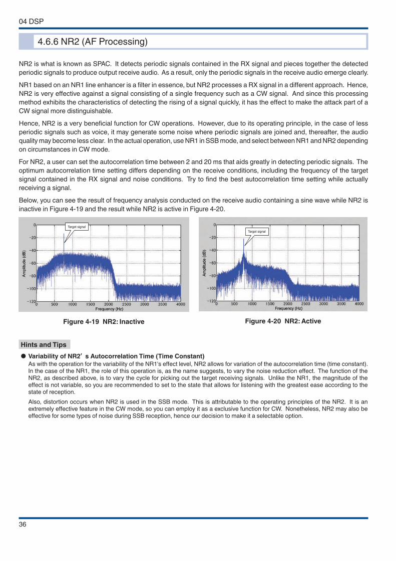
04 DSP
36
Target signal
Figure 4-19 NR2: Inactive
Target signal
Figure 4-20 NR2: Active
Hints and Tips
● Variability of NR2’ s Autocorrelation Time (Time Constant)
As with the operation for the variability of the NR1's effect level, NR2 allows for variation of the autocorrelation time (time constant). In the case of the NR1, the role of this operation is, as the name suggests, to vary the noise reduction effect. The function of the NR2, as described above, is to vary the cycle for picking out the target receiving signals. Unlike the NR1, the magnitude of the effect is not variable, so you are recommended to set to the state that allows for listening with the greatest ease according to the state of reception.
Also, distortion occurs when NR2 is used in the SSB mode. This is attributable to the operating principles of the NR2. It is an extremely effective feature in the CW mode, so you can employ it as a exclusive function for CW. Nonetheless, NR2 may also be effective for some types of noise during SSB reception, hence our decision to make it a selectable option.
4.6.6 NR2 (AF Processing)
NR2 is what is known as SPAC. It detects periodic signals contained in the RX signal and pieces together the detected
periodic signals to produce output receive audio. As a result, only the periodic signals in the receive audio emerge clearly.
NR1 based on an NR1 line enhancer is a filter in essence, but NR2 processes a RX signal in a different approach. Hence,
NR2 is very effective against a signal consisting of a single frequency such as a CW signal. And since this processing
method exhibits the characteristics of detecting the rising of a signal quickly, it has the effect to make the attack part of a
CW signal more distinguishable.
Hence, NR2 is a very beneficial function for CW operations. However, due to its operating principle, in the case of less
periodic signals such as voice, it may generate some noise where periodic signals are joined and, thereafter, the audio
quality may become less clear. In the actual operation, use NR1 in SSB mode, and select between NR1 and NR2 depending
on circumstances in CW mode.
For NR2, a user can set the autocorrelation time between 2 and 20 ms that aids greatly in detecting periodic signals. The
optimum autocorrelation time setting differs depending on the receive conditions, including the frequency of the target
signal contained in the RX signal and noise conditions. Try to find the best autocorrelation time setting while actually
receiving a signal.
Below, you can see the result of frequency analysis conducted on the receive audio containing a sine wave while NR2 is
inactive in Figure 4-19 and the result while NR2 is active in Figure 4-20.
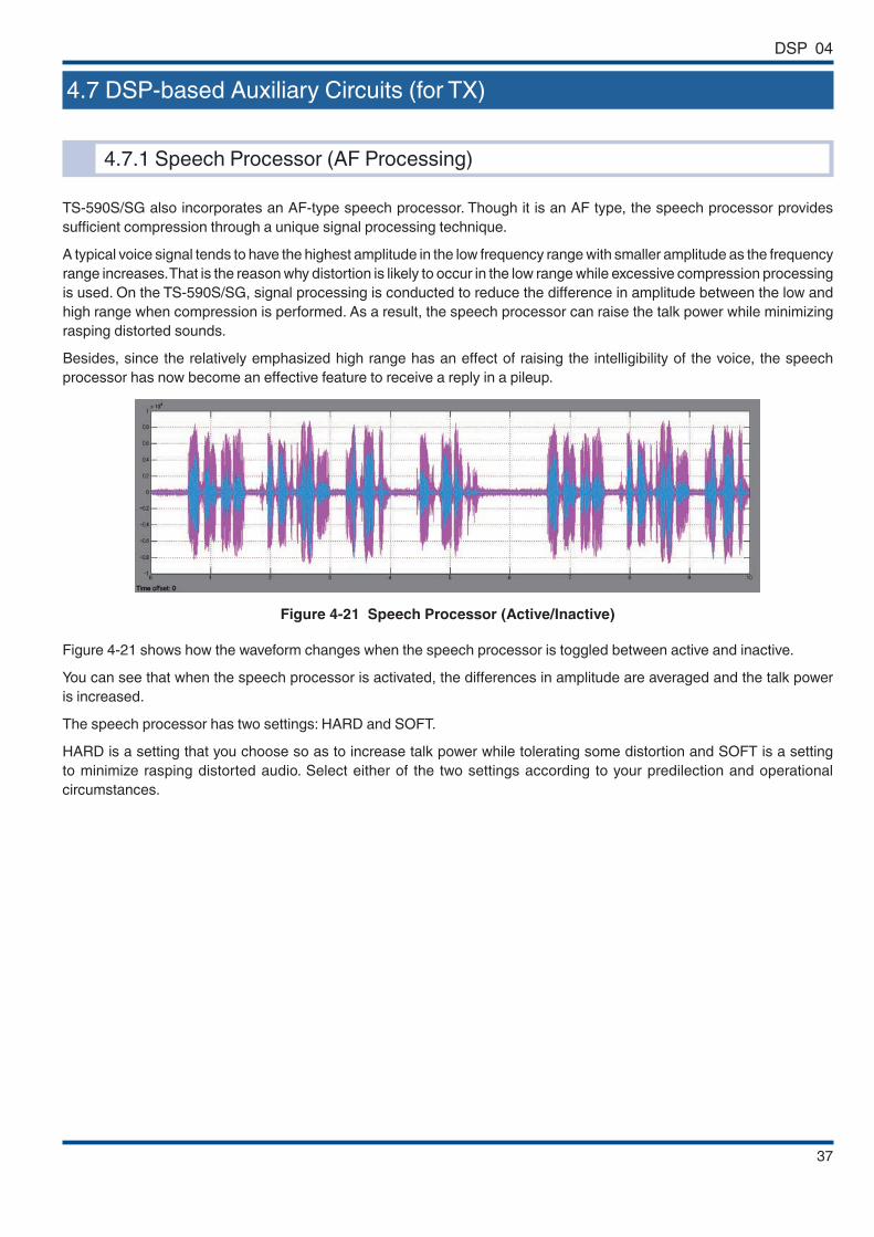
DSP 04
37
4.7 DSP-based Auxiliary Circuits (for TX)
4.7.1 Speech Processor (AF Processing)
TS-590S/SG also incorporates an AF-type speech processor. Though it is an AF type, the speech processor provides
sufficient compression through a unique signal processing technique.
A typical voice signal tends to have the highest amplitude in the low frequency range with smaller amplitude as the frequency
range increases. That is the reason why distortion is likely to occur in the low range while excessive compression processing
is used. On the TS-590S/SG, signal processing is conducted to reduce the difference in amplitude between the low and
high range when compression is performed. As a result, the speech processor can raise the talk power while minimizing
rasping distorted sounds.
Besides, since the relatively emphasized high range has an effect of raising the intelligibility of the voice, the speech
processor has now become an effective feature to receive a reply in a pileup.
Figure 4-21 Speech Processor (Active/Inactive)
Figure 4-21 shows how the waveform changes when the speech processor is toggled between active and inactive.
You can see that when the speech processor is activated, the differences in amplitude are averaged and the talk power
is increased.
The speech processor has two settings: HARD and SOFT.
HARD is a setting that you choose so as to increase talk power while tolerating some distortion and SOFT is a setting
to minimize rasping distorted audio. Select either of the two settings according to your predilection and operational
circumstances.
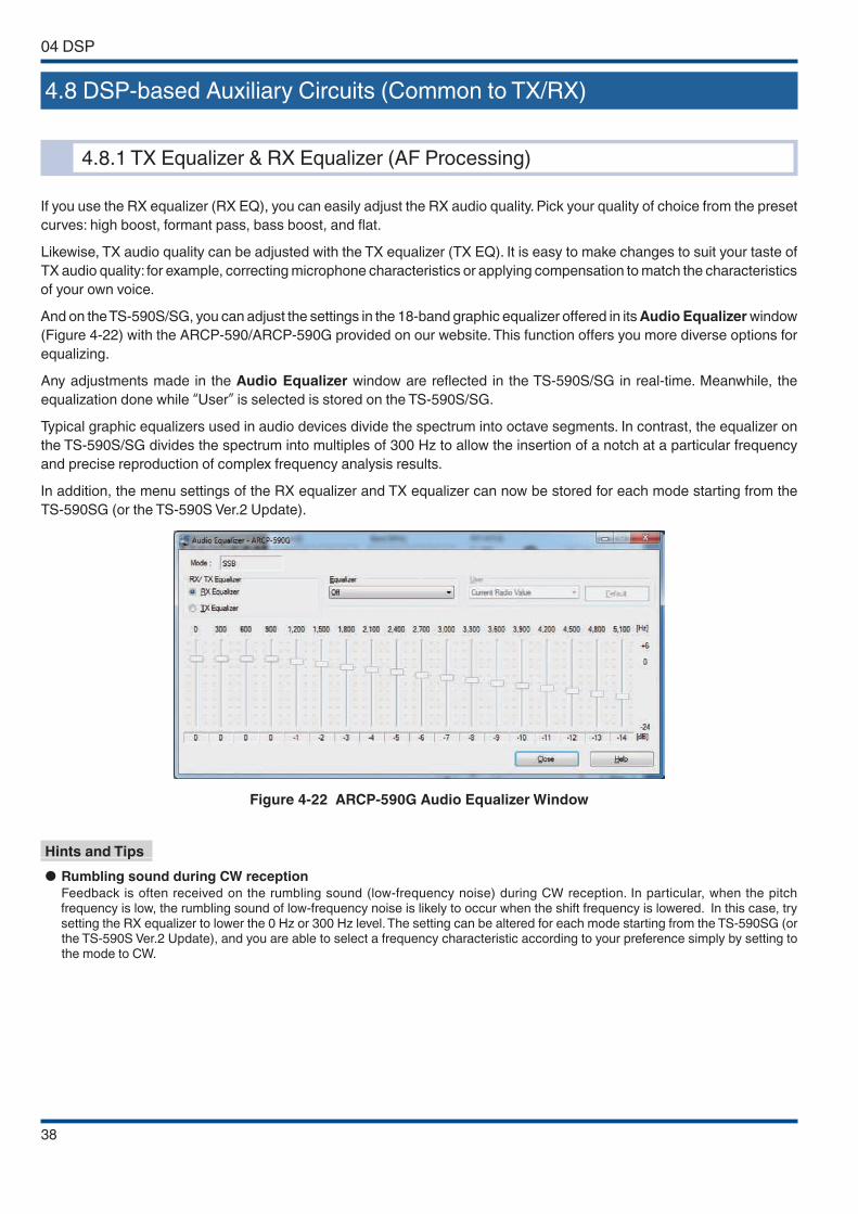
04 DSP
38
4.8 DSP-based Auxiliary Circuits (Common to TX/RX)
4.8.1 TX Equalizer & RX Equalizer (AF Processing)
If you use the RX equalizer (RX EQ), you can easily adjust the RX audio quality. Pick your quality of choice from the preset
curves: high boost, formant pass, bass boost, and flat.
Likewise, TX audio quality can be adjusted with the TX equalizer (TX EQ). It is easy to make changes to suit your taste of
TX audio quality: for example, correcting microphone characteristics or applying compensation to match the characteristics
of your own voice.
And on the TS-590S/SG, you can adjust the settings in the 18-band graphic equalizer offered in its Audio Equalizer window
(Figure 4-22) with the ARCP-590/ARCP-590G provided on our website. This function offers you more diverse options for
equalizing.
Any adjustments made in the Audio Equalizer window are reflected in the TS-590S/SG in real-time. Meanwhile, the
equalization done while “User” is selected is stored on the TS-590S/SG.
Typical graphic equalizers used in audio devices divide the spectrum into octave segments. In contrast, the equalizer on
the TS-590S/SG divides the spectrum into multiples of 300 Hz to allow the insertion of a notch at a particular frequency
and precise reproduction of complex frequency analysis results.
In addition, the menu settings of the RX equalizer and TX equalizer can now be stored for each mode starting from the
TS-590SG (or the TS-590S Ver.2 Update).
Figure 4-22 ARCP-590G Audio Equalizer Window
Hints and Tips
● Rumbling sound during CW reception
Feedback is often received on the rumbling sound (low-frequency noise) during CW reception. In particular, when the pitch frequency is low, the rumbling sound of low-frequency noise is likely to occur when the shift frequency is lowered. In this case, try setting the RX equalizer to lower the 0 Hz or 300 Hz level. The setting can be altered for each mode starting from the TS-590SG (or the TS-590S Ver.2 Update), and you are able to select a frequency characteristic according to your preference simply by setting to the mode to CW.

39
In addition to the features we have explained thus far, the TS-590S/SG comes with extensive functions to make your
operation more pleasant. We will guide you through some of them.
5.1 Extended Data-mode Related Functions
We have modified data-mode related settings to meet many different needs.
Figure 5-1 Front Panel of the TS-590S/SG
In SSB-DATA, AM-DATA and FM-DATA modes, the On/Off settings of the speech processor and the settings of DSP filters
are stored independently of the normal SSB, AM and FM modes. Hence, you can conveniently switch between the data
mode operation and the normal mode operation with a single touch of a button.
Also, now that USB audio functions*1 accept external audio input/output, operations in combination with a PC have become
more convenient. The audio output of the TS-590S/SG can be easily delivered to a PC simply by connecting the transceiver
and the PC using a single USB cable. If you select “USB” in “Audio input line selection for data communications” of Menu
69, you can transmit using an audio source from a PC.
Setting the "DATA VOX" function to ON in Menu 76 enables transmission automatically according to the audio input from
the PC.
To transmit via key operation, assign “DATA SEND” to the PF key in menu mode. It is also possible to transmit using the
PKS signal in the ACC2 connector as before.
The PC command “TX1;” is used for transmitting the external input audio using the PC controller.
Furthermore, TS-590SG can transmit the external input audio according to the SEND/PTT or SS signal during DATA mode.
Setting the “SOURCE OF SEND/PTT TRANSMISSION” in Menu 70 to “REAR” (input connector on the rear panel) switches
the transmission source in conjunction with enabling or disabling the DATA mode. When DATA mode is enabled, audio is
transmitted from the PC; and when Data Mode is disabled, the microphone input audio is transmitted.
*1 The USB audio interface has latency (signal delay) due to a limitation resulting from the specifications. So use it for communications where time lag is not an issue.
05 SOFTWARE: ENHANCING OPERATING PLEASURE
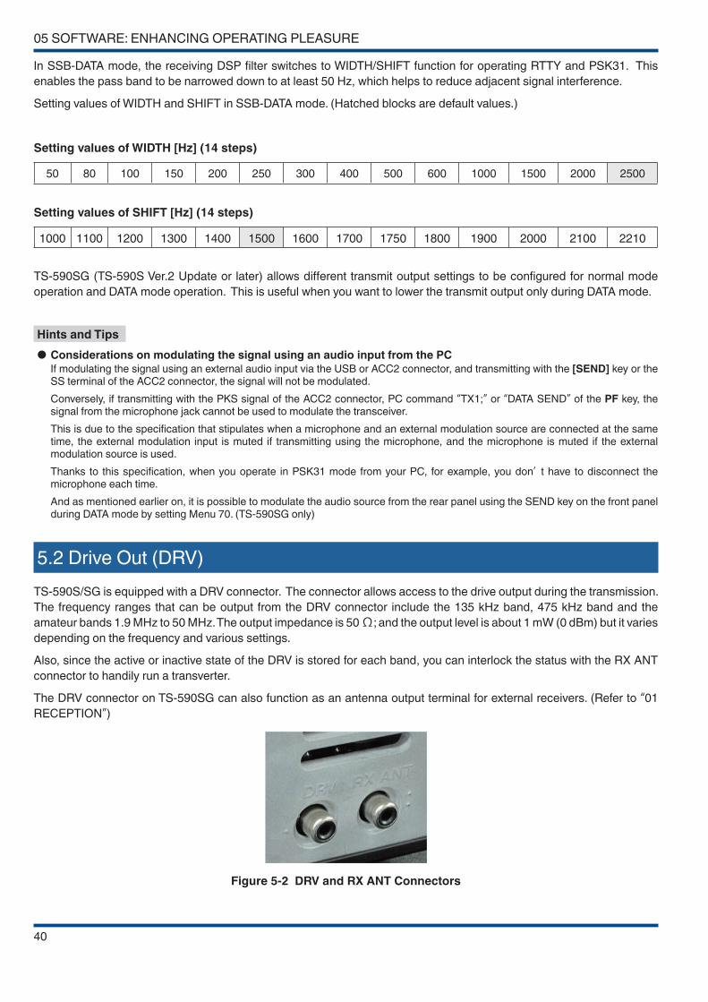
05 SOFTWARE: ENHANCING OPERATING PLEASURE
40
In SSB-DATA mode, the receiving DSP filter switches to WIDTH/SHIFT function for operating RTTY and PSK31. This
enables the pass band to be narrowed down to at least 50 Hz, which helps to reduce adjacent signal interference.
Setting values of WIDTH and SHIFT in SSB-DATA mode. (Hatched blocks are default values.)
Setting values of WIDTH [Hz] (14 steps)
50 80 100 150 200 250 300 400 500 600 1000 1500 2000 2500
Setting values of SHIFT [Hz] (14 steps)
1000 1100 1200 1300 1400 1500 1600 1700 1750 1800 1900 2000 2100 2210
TS-590SG (TS-590S Ver.2 Update or later) allows different transmit output settings to be configured for normal mode
operation and DATA mode operation. This is useful when you want to lower the transmit output only during DATA mode.
Hints and Tips
● Considerations on modulating the signal using an audio input from the PC
If modulating the signal using an external audio input via the USB or ACC2 connector, and transmitting with the [SEND] key or the SS terminal of the ACC2 connector, the signal will not be modulated.
Conversely, if transmitting with the PKS signal of the ACC2 connector, PC command “TX1;” or “DATA SEND” of the PF key, the signal from the microphone jack cannot be used to modulate the transceiver.
This is due to the specification that stipulates when a microphone and an external modulation source are connected at the same time, the external modulation input is muted if transmitting using the microphone, and the microphone is muted if the external modulation source is used.
Thanks to this specification, when you operate in PSK31 mode from your PC, for example, you don’ t have to disconnect the microphone each time.
And as mentioned earlier on, it is possible to modulate the audio source from the rear panel using the SEND key on the front panel during DATA mode by setting Menu 70. (TS-590SG only)
5.2 Drive Out (DRV)
TS-590S/SG is equipped with a DRV connector. The connector allows access to the drive output during the transmission.
The frequency ranges that can be output from the DRV connector include the 135 kHz band, 475 kHz band and the
amateur bands 1.9 MHz to 50 MHz. The output impedance is 50 Ω; and the output level is about 1 mW (0 dBm) but it varies
depending on the frequency and various settings.
Also, since the active or inactive state of the DRV is stored for each band, you can interlock the status with the RX ANT
connector to handily run a transverter.
The DRV connector on TS-590SG can also function as an antenna output terminal for external receivers. (Refer to “01
RECEPTION”)
Figure 5-2 DRV and RX ANT Connectors

SOFTWARE: ENHANCING OPERATING PLEASURE 05
41
5.3 Single Button Toggles IF Filters between A and B
For use of the legendary slope tuning and WIDTH/SHIFT functions incorporated in successive KENWOOD HF transceivers,
TS-590S/SG stores the status of two filters (FILTER A and FILTER B) set for each type of signal. Hence, you can easily
switch between the filters with a single touch of a button.
Figure 5-3 [IF FIL] Key
As an example, store the setting of a wide IF filter and narrow IF filter in FILTER A and FILTER B respectively. When you
look for a station for a contact, use the wider FILTER A and once you have started a QSO, switch to the narrower FILTER
B, with a touch of a button, to be able to receive the target signal only .
For TS-590SG (TS-590S Ver.2 Update or later), improvements have been made to the storing of the selective states of
FILTER A and FILTER B using VFO A and VFO B respectively. This enhances user convenience during split operation; the
VFO at the receiving end uses the narrow bandwidth FILTER A to remove the interference and the VFO at the transmitting
end uses the wide bandwidth FILTER B to check the signal condition near the transmitting frequency via TF-SET.
Hints and Tips
● Is this filter switchover with a single touch of a button different from NAR?
This filter switchover with a single action is based on the way the NAR function was used in the days when analog IF filters were used. Continuously, variable bandwidth is convenient in the sense that you can adjust it freely to whatever value you choose, but you may have difficulty operating in a timely manner in a contest or similar because it does not allow a jump to a certain value instantaneously. Therefore, we considered introducing a mechanism equivalent to the previous NAR function, but we were swayed by the opinion that a user wants to operate with normal bandwidth usually, yet still maintain the to switch to a wider bandwidth when it is required. Consequently, to satisfy both needs, we have devised a system to store settings freely.

05 SOFTWARE: ENHANCING OPERATING PLEASURE
42
5.4 New Split Frequency Setting Method
TS-590SG (TS-590S Ver. 2.0 or later) makes use of the new split transmit frequency method adopted by the TS-990S,
allowing for pileup to start quickly.
Once the transmitting frequency of the station at the other end (receiving frequency) is fixed, press and hold the [SPLIT]
key. When the SPLIT pictogram starts to blink, press the "5" numeric key in the case of "Up 5 kHz". In the case of "Down
5 kHz", press the "0" key, followed by pressing "5". Split setting is now complete.
5.5 Split Operation Using XIT
For TS-590SG, the TF-SET function is operable during split operation using XIT. (TS-590S Ver.2 Update or later)
When you find a DX station using split mode, turn on RIT/XIT at the same time, and operate the [RIT/XIT] knob to look for
the (receiving) frequency that the DX station responds to. Next, turn off RIT only. Setting for split operation is now complete.
Pressing the TF-SET key in this state allows you to receive and check the transmitting frequency of your own station.
5.6 Improved FINE Mode
FINE mode function sets the frequency step of the [TUNE] knob to 1/10. Previously, FINE mode has been common to all
modes. The specification for TS-590SG (TS-590S Ver.2 Update or later) has been improved to allow separate setting for each
mode (SSB/ SSB-DATA/ CW/ FSK/ FM/ AM). For example, the normal SSB operation uses 10 Hz step, and when PSK31
is operating in SSB-DATA mode, you can enable FINE mode in SSB-DATA mode alone where fine tuning step is required.
And if FINE mode is enabled for frequency below 1 MHz, the display shifts one digit to the left of the display frequency to
display in units of 1 Hz.
5.7 Optimizing the Frequency Step (MULTI/CH Knob)
The [MULTI/CH] knob allows you to change the frequency in more coarse tuning steps than the [TUNE] knob. This frequency
step can also be changed in the menu.
SSB/CW/FSK settings, AM settings, and FM settings existed separately in the past. On the TS-590SG, SSB settings are
separated from the CW/FSK settings to enable selection of the optimal frequency step for each mode.
The default setting is 5 kHz step for SSB mode and 500 Hz step for CW/ FSK mode.
5.8 PF Keys
The TS-590S/SG incorporates two PF keys instead of the conventional one to enhance user convenience. Some functions
can be assigned only to the PF keys, so as to use the PF keys as required by the operational circumstances.
Furthermore, the MULTI/CH knob on TS-590SG has been modified to also function as a push switch and can be used as a
PF key. By default, the knob is assigned with keying speed setting when the transmit mode is CW and assigned with transmit
out setting when the transmit mode is other than CW. (You can assign it with other function using the menu.) Assigning
function that is frequently used with the MULTI/CH knob operation to this PF key will make the operation more convenient.
In addition, the [RIT], [XIT] and [CL] keys on the top right corner of the front panel can also be used as PF keys. By default,
functions as indicated by the silk print on the keys are assigned but you can change to other functions using the menu.
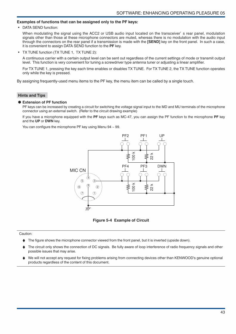
SOFTWARE: ENHANCING OPERATING PLEASURE 05
43
Examples of functions that can be assigned only to the PF keys:
• DATA SEND function:
When modulating the signal using the ACC2 or USB audio input located on the transceiver’ s rear panel, modulation signals other than those at these microphone connectors are muted, whereas there is no modulation with the audio input through the connectors on the rear panel if a transmission is made with the [SEND] key on the front panel. In such a case, it is convenient to assign DATA SEND function to the PF key.
• TX TUNE function (TX TUNE 1, TX TUNE 2):
A continuous carrier with a certain output level can be sent out regardless of the current settings of mode or transmit output level. This function is very convenient for tuning a screwdriver type antenna tuner or adjusting a linear amplifier.
For TX TUNE 1, pressing the key each time enables or disables TX TUNE. For TX TUNE 2, the TX TUNE function operates only while the key is pressed.
By assigning frequently-used menu items to the PF key, the menu item can be called by a single touch.
Hints and Tips
● Extension of PF function
PF keys can be increased by creating a circuit for switching the voltage signal input to the MD and MU terminals of the microphone connector using an external switch. (Refer to the circuit drawing example)
If you have a microphone equipped with the PF keys such as MC-47, you can assign the PF function to the microphone PF key and the UP or DWN key.
You can configure the microphone PF key using Menu 94 ~ 99.
1
2
34
5
6
7
8
PF2 PF1 UP
PF4 PF3 DWNMIC CN
10
0 k
22
k
10
0 k
22
k
Figure 5-4 Example of Circuit
Caution:
◆ The figure shows the microphone connector viewed from the front panel, but it is inverted (upside down).
◆ The circuit only shows the connection of DC signals. Be fully aware of loop interference of radio frequency signals and other
possible issues that may arise.
◆ We will not accept any request for fixing problems arising from connecting devices other than KENWOOD's genuine optional
products regardless of the content of this document.
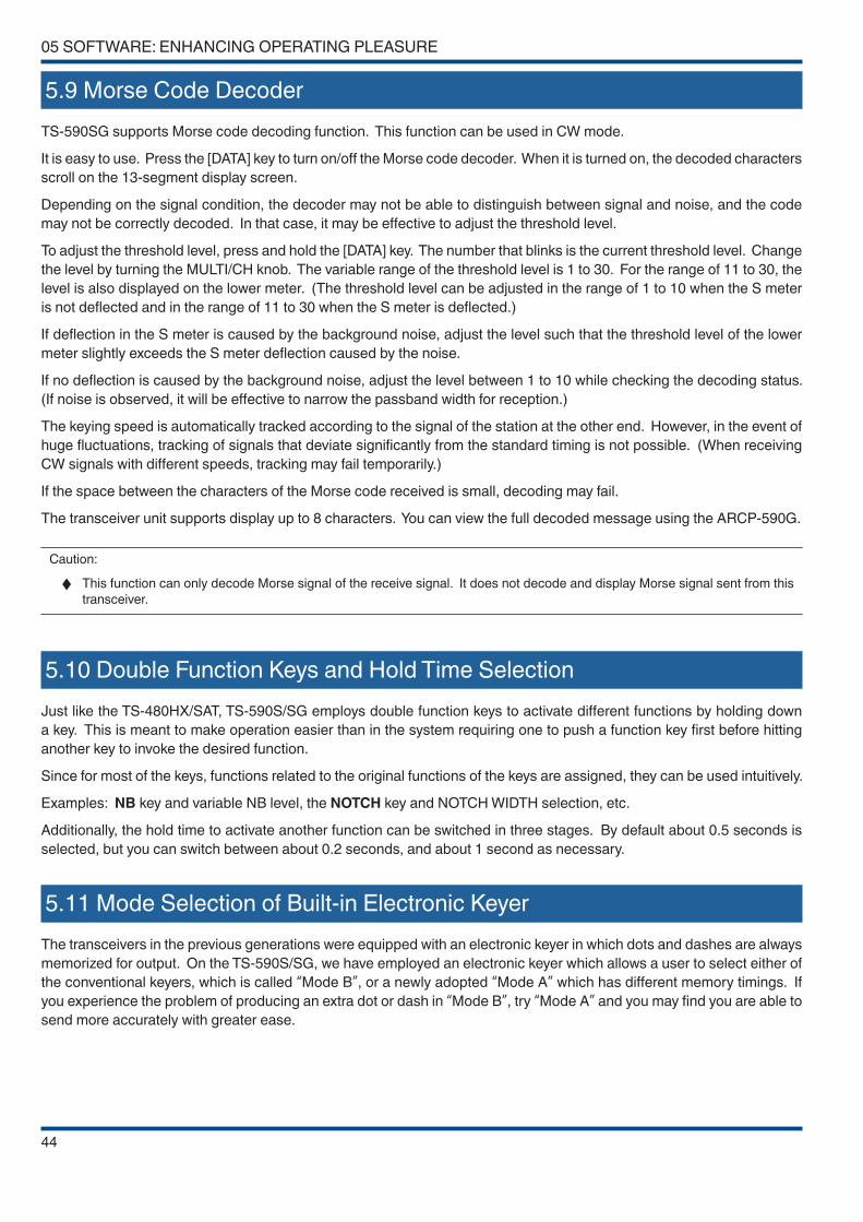
05 SOFTWARE: ENHANCING OPERATING PLEASURE
44
5.9 Morse Code Decoder
TS-590SG supports Morse code decoding function. This function can be used in CW mode.
It is easy to use. Press the [DATA] key to turn on/off the Morse code decoder. When it is turned on, the decoded characters
scroll on the 13-segment display screen.
Depending on the signal condition, the decoder may not be able to distinguish between signal and noise, and the code
may not be correctly decoded. In that case, it may be effective to adjust the threshold level.
To adjust the threshold level, press and hold the [DATA] key. The number that blinks is the current threshold level. Change
the level by turning the MULTI/CH knob. The variable range of the threshold level is 1 to 30. For the range of 11 to 30, the
level is also displayed on the lower meter. (The threshold level can be adjusted in the range of 1 to 10 when the S meter
is not deflected and in the range of 11 to 30 when the S meter is deflected.)
If deflection in the S meter is caused by the background noise, adjust the level such that the threshold level of the lower
meter slightly exceeds the S meter deflection caused by the noise.
If no deflection is caused by the background noise, adjust the level between 1 to 10 while checking the decoding status.
(If noise is observed, it will be effective to narrow the passband width for reception.)
The keying speed is automatically tracked according to the signal of the station at the other end. However, in the event of
huge fluctuations, tracking of signals that deviate significantly from the standard timing is not possible. (When receiving
CW signals with different speeds, tracking may fail temporarily.)
If the space between the characters of the Morse code received is small, decoding may fail.
The transceiver unit supports display up to 8 characters. You can view the full decoded message using the ARCP-590G.
Caution:
◆ This function can only decode Morse signal of the receive signal. It does not decode and display Morse signal sent from this
transceiver.
5.10 Double Function Keys and Hold Time Selection
Just like the TS-480HX/SAT, TS-590S/SG employs double function keys to activate different functions by holding down
a key. This is meant to make operation easier than in the system requiring one to push a function key first before hitting
another key to invoke the desired function.
Since for most of the keys, functions related to the original functions of the keys are assigned, they can be used intuitively.
Examples: NB key and variable NB level, the NOTCH key and NOTCH WIDTH selection, etc.
Additionally, the hold time to activate another function can be switched in three stages. By default about 0.5 seconds is
selected, but you can switch between about 0.2 seconds, and about 1 second as necessary.
5.11 Mode Selection of Built-in Electronic Keyer
The transceivers in the previous generations were equipped with an electronic keyer in which dots and dashes are always
memorized for output. On the TS-590S/SG, we have employed an electronic keyer which allows a user to select either of
the conventional keyers, which is called “Mode B”, or a newly adopted “Mode A” which has different memory timings. If
you experience the problem of producing an extra dot or dash in “Mode B”, try “Mode A” and you may find you are able to
send more accurately with greater ease.
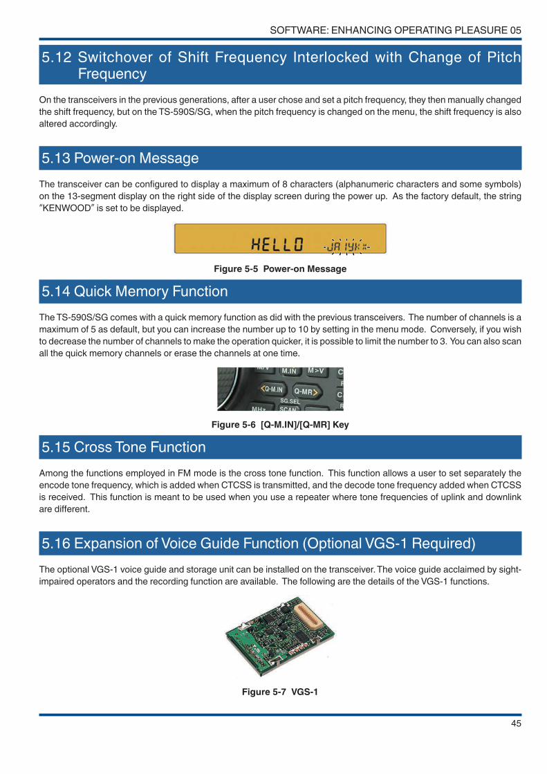
SOFTWARE: ENHANCING OPERATING PLEASURE 05
45
5.12 Switchover of Shift Frequency Interlocked with Change of Pitch Frequency
On the transceivers in the previous generations, after a user chose and set a pitch frequency, they then manually changed
the shift frequency, but on the TS-590S/SG, when the pitch frequency is changed on the menu, the shift frequency is also
altered accordingly.
5.13 Power-on Message
The transceiver can be configured to display a maximum of 8 characters (alphanumeric characters and some symbols)
on the 13-segment display on the right side of the display screen during the power up. As the factory default, the string
“KENWOOD” is set to be displayed.
Figure 5-5 Power-on Message
5.14 Quick Memory Function
The TS-590S/SG comes with a quick memory function as did with the previous transceivers. The number of channels is a
maximum of 5 as default, but you can increase the number up to 10 by setting in the menu mode. Conversely, if you wish
to decrease the number of channels to make the operation quicker, it is possible to limit the number to 3. You can also scan
all the quick memory channels or erase the channels at one time.
Figure 5-6 [Q-M.IN]/[Q-MR] Key
5.15 Cross Tone Function
Among the functions employed in FM mode is the cross tone function. This function allows a user to set separately the
encode tone frequency, which is added when CTCSS is transmitted, and the decode tone frequency added when CTCSS
is received. This function is meant to be used when you use a repeater where tone frequencies of uplink and downlink
are different.
5.16 Expansion of Voice Guide Function (Optional VGS-1 Required)
The optional VGS-1 voice guide and storage unit can be installed on the transceiver. The voice guide acclaimed by sight-
impaired operators and the recording function are available. The following are the details of the VGS-1 functions.
Figure 5-7 VGS-1

05 SOFTWARE: ENHANCING OPERATING PLEASURE
46
Voice Guide Function
On the TS-590S/SG, in addition to the conventional audio announcements, the readings of the multimeter (SWR meter,
ALC meter and COMP meter) can be also announced.
Also, by setting the auto announcement to be disabled in the menu mode, the announcements can be made only when
the VOICE key (that is to be assigned to the PF key) is pressed.
On the TS-590SG (TS-590S Ver.2 Update or later), there are now more announcement items, such as that on the RIT/XIT
status and when the ALC/SWR/COMP meter is switched.
Voice Message Memory Function
A maximum of four channels can be used for recording voice messages. This is a very convenient option for an operator
who participates in a contest in SSB mode. (The CW message memory function is available on the transceiver and does
not require VGS-1.)
And channel 4 can be assigned as the channel for constant recording. Anytime upon a long press of the [RX/4] key, you
can store the voice signal received over the past 30 seconds in a flash memory and replay the voice as required.
On the TS-590SG (TS-590S Ver.2 Update or later), you can adjust the mic gain during transmission of a voice message
(modulation input level) as well as the input and output level of the speech processor. (Adjustment for voice message
transmission can be made while retaining the setting when sending a mic signal.)
Hints and Tips
● Message transmission using VGS-1
To use VGS-1 to transmit a voice message, turn on the VOX function. However, this will activate the VOX function when there is audio input to the microphone. To avoid activating the VOX function when transmitting using the microphone, set the VOX gain to "0" while the VOX function is turned on. With this setting, the audio input to the microphone does not activate the VOX function, only voice message transmission is carried out.
Hints and Tips
● What are the projections on the rear panel for?
On the rear panel of the TS-590S/SG, projections are placed near some connectors.
Figure 5-8 Projections on the Rear Panel
We have provided these guides to meet the demands from sight-impaired operators who wish to set up the transceiver without help from someone else. If two identical connectors are placed side by side, you can not tell them apart just by feeling them. The projections are provided so that the applications of the connectors can be easily distinguished.
These projections will allow a sight-impaired person to understand the positional relationship of the connectors easily by feeling the rear panel with their fingers.
Also, a transceiver is often placed on a rack and a user is sometimes forced to connect cables without seeing them. The projections will also help you in such a situation. This careful attention is also part of KENWOOD's efforts for “accessibility improvement” based on “easy operation” .
Projections are provided near the following connectors: DRV, RX, ANT, ANT1, and ANT2.
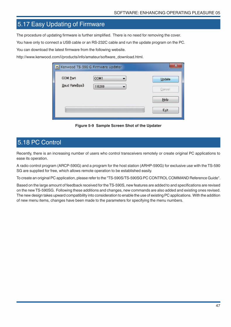
SOFTWARE: ENHANCING OPERATING PLEASURE 05
47
5.17 Easy Updating of Firmware
The procedure of updating firmware is further simplified. There is no need for removing the cover.
You have only to connect a USB cable or an RS-232C cable and run the update program on the PC.
You can download the latest firmware from the following website.
http://www.kenwood.com/i/products/info/amateur/software_download.html.
Figure 5-9 Sample Screen Shot of the Updater
5.18 PC Control
Recently, there is an increasing number of users who control transceivers remotely or create original PC applications to
ease its operation.
A radio control program (ARCP-590G) and a program for the host station (ARHP-590G) for exclusive use with the TS-590
SG are supplied for free, which allows remote operation to be established easily.
To create an original PC application, please refer to the "TS-590S/TS-590SG PC CONTROL COMMAND Reference Guide".
Based on the large amount of feedback received for the TS-590S, new features are added to and specifications are revised
on the new TS-590SG. Following these additions and changes, new commands are also added and existing ones revised.
The new design takes upward compatibility into consideration to enable the use of existing PC applications. With the addition
of new menu items, changes have been made to the parameters for specifying the menu numbers.
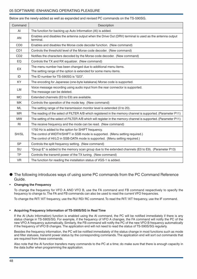
05 SOFTWARE: ENHANCING OPERATING PLEASURE
48
Below are the newly-added as well as expanded and revised PC commands on the TS-590SG.
Command Description
AI The function for backing up Auto Information (AI) is added.
ANEnables and disables the antenna output when the Drive Out (DRV) terminal is used as the antenna output terminal.
CD0 Enables and disables the Morse code decoder function. (New command)
CD1 Controls the threshold level of the Morse code decoder. (New command)
CD2 Notifies the characters decoded by the Morse code decoder. (New command)
EQ Controls the TX and RX equalizer. (New command)
EXThe menu number has been changed due to additional menu items.
The setting range of the option is extended for some menu items.
ID The ID number for TS-590SG is "023".
KY The encoding for Japanese (one-byte katakana) Morse code is supported.
LMVoice message recording using audio input from the rear connector is supported.
The message can be deleted.
MC Extended channels (E0 to E9) are available.
MK Controls the operation of the mode key. (New command)
ML The setting range of the transmission monitor level is extended (0 to 20).
MR The reading of the select of FILTER A/B which registered in the memory channel is supported. (Parameter P11)
MW The setting of the select of FILTER A/B which will register in the memory channel is supported. (Parameter P11)
RI The receive frequency and the mode can be read. (New command)
SH/SL
1750 Hz is added to the option for SHIFT frequency.
The control of WIDTH/SHIFT in SSB mode is supported. (Menu setting required.)
The control of HI/LO in SSB-DATA mode is supported. (Menu setting required.)
SP Controls the split frequency setting. (New command)
SU "Group E" is added to the memory scan group due to the extended channels (E0 to E9). (Parameter P13)
TP Controls the transmit power of the TX tuning. (New command)
VR The function for reading the installation status of VGS-1 is added.
● The following introduces ways of using some PC commands from the PC Command Reference Guide.
• Changing the Frequency
To change the frequency for VFO A AND VFO B, use the FA command and FB command respectively to specify the frequency to change to. The FA and FB commands can also be used to read the current VFO frequencies.
To change the RIT/ XIT frequency, use the RU/ RD/ RC command. To read the RIT/ XIT frequency, use the IF command.
• Acquiring Frequency Information of TS-590S/SG in Real Time
If the AI (Auto Information) function is enabled using the AI command, the PC will be notified immediately if there is any status change in TS-590S/SG. For example, if the frequency of VFO A changes, the FA command will notify the PC of the new VFO A frequency automatically. Similarly, the FB command will notify the PC of the new VFO B frequency automatically if the frequency of VFO B changes. The application end will not need to read the status of TS-590S/SG regularly.
Besides the frequency information, the PC will be notified immediately of the status change in most functions such as mode and filter statuses, transmit power status by the corresponding commands. The application end will sort out commands that are required from these commands.
Also note that the AI function transfers many commands to the PC at a time; do make sure that there is enough capacity in the data buffer when programming the application.
SOFTWARE: ENHANCING OPERATING PLEASURE 05
49
• Switching to Split Mode
To use command to switch to split mode, use the FR and FT command.
For example, to set to the split mode that uses VFO A to receive and VFO B to transmit, first send “FR0;” using the FR command to set VFO A as the receiving end. This is known as VFO A simplex mode when used as is. Next, send “FT1;” using the FT command to set VFO B as the transmitting end.
The FR command is a command to set to simplex mode, and the FT command is a command to set to split mode.
• Transmitting Audio Signal that Is Input to the Rear Connector
Begin by specifying the connector to be used (ACC2 or USB). Specify this using Menu 69. To operate using command, use the EX command. (Once it has been set, the setting will be stored.)
To begin transmitting, specify the parameter of the TX command to “TX1;” (transmit with PF [DATA SEND] key). (To restore back to receiving, use the RX command.)
If you begin transmitting using “TX;” (without parameter) or “TX0;” , the audio input to the microphone will be transmitted when you operate the [PTT] key or [SEND] key.
• TX Tuning
TX tuning is a function to transmit a constant output carrier continuously. Using this function allows you to tune the linear amplifier without having to change the mode. Use this function by assigning it to the PF key on the front panel. To perform TX tuning using command, use “TX2;” to start TX tuning and “RX;” to stop TX tuning.
The transmit power for TX tuning is set using the TP command.
• Sending CW Morse Code
You can use the KY command to send Morse code.
For example, to send a Morse code "CQ CQ CQ DE JA1 YKX", send the command "KY CQ CQ CQ DE JA1YKX ;" to TS-590S/SG. If TS-590S/SG is in the CW mode and break-in is active, the CW Morse code will be sent.
Up to 24 characters can be input for the message using the KY command. Please insert space if the message contains less than 24 characters like the above example. If the message contains more than 24 characters, it will be divided into multiple messages before sending. To stop keying, use the “KY0;” . To change the keying speed, use the KS command.

50
06 APPEARANCE DESIGN: “DESIGN CONCEPT” REVEALED BY DESIGNING ENGINEER
The design development of the TS-590S was started by asking myself “What are the characteristics that make KENWOOD’s
HF transceivers just what they are?” Among the key words adopted to describe the characteristics were “innovativeness”, “high quality” and “sharpness”, based on which I pursued a design that captures the trends of the times.
On the development of TS-590S, I exchanged lively discussions with my colleagues and finally settled on the design concept
of “deep and heavy”. This means “a genuine HF transceiver that nobody can make light of” or “a design that, when it is
placed among other peripheral devices in a shack (which is inevitable due to the nature of the product), does not stand
out distastefully”.
The work of designing a transceiver does not end with just creating an outer shape, but includes a wide variety of tasks
ranging from scrutinizing colors, materials, character fonts, etc., to examining the size, thickness and balance of characters
displayed on the LCD.
A horizontal line penetrating the front panel describes the sharpness and the DNA of KENWOOD’s HF transceivers that
has been handed down from generation to generation.
When it comes to the main knob that a user touches most often, I have devised a design that never makes a user tired from
long hours of operation or slips out of the hand while handling. Also, for the material I have employed fluorine-containing
rubber that does not attract dirt and dust.
As for the color of the body, I have selected matte-black finish to give it a typical look of a transceiver and to prevent the
reflection of light as much as possible when a user operates from a portable station.
Much attention is also paid to the printing of the characters and graphics to express the typical preciseness of KENWOOD’s
HF transceivers and to deliver better visibility to enable intuitive operations and eye-friendly views.
TS-990S was released about two years after the TS-590S was launched. While the TS-990S seems to have inherited the
design of the TS-590S, as explained in the in-depth manual for the TS-990S, both models were derived from the same
design concept.
TS-990S has been designed to exude a luxurious feel that befits its name as KENWOOD's flagship model. The TS-590SG
series adopts the elegance of the TS-990S without making changes to the basic design to ensure excellent operability.
Some examples include the surface finish of the main knob, the coating on the outside of the two axis knobs, the silk color of
the front panel, and the paint for the top and bottom covers. While it may not be easy to tell the differences from the photos,
you can tell that the TS-590SG shares more similarities with the TS-990S if the new and old models are placed side by side.
Hints and Tips
● Differentiating TS-590S and TS-590SG
Even if the power is not turned on, you can easily differentiate by the silk printing on the top right corner of the display screen. The transceiver is a TS-590S if "DSP" is printed, and a TS-590SG if "TS-590" is printed. If you have both the new and old transceiver, you should be able to tell the different immediately by the shiny main knob.

51
7.1 Cooling
We have designed the chassis of the TS-590S/SG to endure heavy-duty operation.
The PCBs are placed as follows: FINAL UNIT on the upper side of the chassis, TX-RX UNIT and LO UNIT on the lower
side, CONTROL UNIT beneath the LO UNIT, NB UNIT and DISPLAY UNIT in front.
We have placed two cooling fans in the front of the chassis.
The cooling fans have two operation modes: LO and HI. By rotating two fan motors at a lower revolution speed, we aimed
to reduce the operating noise.
FINAL UNIT
TWIN FAN
TX-RX UNIT
LO
UN
IT
NB UNIT
CO
NT
RO
L U
NIT
DISPLAY UNIT
Figure 7-1 Layout of Printed Circuit Boards
We have optimized the chassis structure using computer-aided thermal analysis to improve the heat dissipation performance.
We have designed the chassis to facilitate smooth air flow.
Figure 7-2 Results of Computer-aided Thermal Analysis
07 STRUCTURAL FEATURES

07 STRUCTURAL FEATURES
52
We have also paid much attention to the area and shape of the air inlets/outlets to lessen the operation noise of cooling
fan motors.
To reduce the noise from the air inlets/outlets, the area and shape were examined through repeated experiments and we
have finally succeeded in alleviating the cooling fan motors’ operating noise. The area of air inlets/outlets of the TS-590S/
SG is about 1.5 times larger than that of TS-2000/X so that the suction and emission efficiency is improved.
The following figure portrays the aluminum die-cast chassis of the TS-590S/SG.
Figure 7-3 shows the side of the FINAL UNIT, Figure 7-4 shows the side of the TX-RX UNIT. Final FETs are positioned on
the two raised areas located to the left on the side of the FINAL UNIT. On the reverse side of the final FETs, beneath the
TX-RX UNIT, a heat sink
(Figure 7-5) is placed to remove heat from the final FETs and discharge it.
Figure 7-3 On the Side of FINAL UNIT Figure 7-4 On the Side of TX-RX UNIT
Figure 7-5 Heat Sink Section
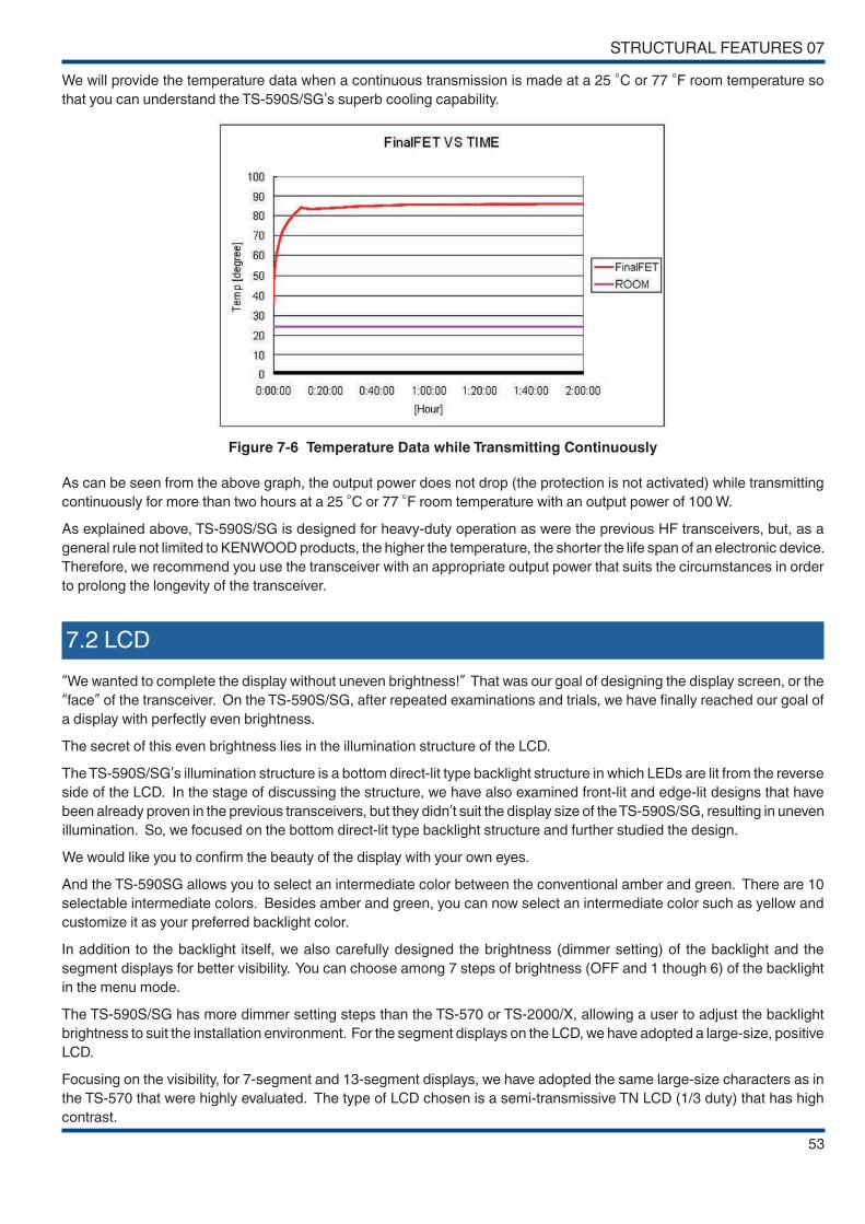
STRUCTURAL FEATURES 07
53
We will provide the temperature data when a continuous transmission is made at a 25 °C or 77 °F room temperature so
that you can understand the TS-590S/SG’s superb cooling capability.
Figure 7-6 Temperature Data while Transmitting Continuously
As can be seen from the above graph, the output power does not drop (the protection is not activated) while transmitting
continuously for more than two hours at a 25 °C or 77 °F room temperature with an output power of 100 W.
As explained above, TS-590S/SG is designed for heavy-duty operation as were the previous HF transceivers, but, as a
general rule not limited to KENWOOD products, the higher the temperature, the shorter the life span of an electronic device.
Therefore, we recommend you use the transceiver with an appropriate output power that suits the circumstances in order
to prolong the longevity of the transceiver.
7.2 LCD
“We wanted to complete the display without uneven brightness!” That was our goal of designing the display screen, or the
“face” of the transceiver. On the TS-590S/SG, after repeated examinations and trials, we have finally reached our goal of
a display with perfectly even brightness.
The secret of this even brightness lies in the illumination structure of the LCD.
The TS-590S/SG’s illumination structure is a bottom direct-lit type backlight structure in which LEDs are lit from the reverse
side of the LCD. In the stage of discussing the structure, we have also examined front-lit and edge-lit designs that have
been already proven in the previous transceivers, but they didn’t suit the display size of the TS-590S/SG, resulting in uneven
illumination. So, we focused on the bottom direct-lit type backlight structure and further studied the design.
We would like you to confirm the beauty of the display with your own eyes.
And the TS-590SG allows you to select an intermediate color between the conventional amber and green. There are 10
selectable intermediate colors. Besides amber and green, you can now select an intermediate color such as yellow and
customize it as your preferred backlight color.
In addition to the backlight itself, we also carefully designed the brightness (dimmer setting) of the backlight and the
segment displays for better visibility. You can choose among 7 steps of brightness (OFF and 1 though 6) of the backlight
in the menu mode.
The TS-590S/SG has more dimmer setting steps than the TS-570 or TS-2000/X, allowing a user to adjust the backlight
brightness to suit the installation environment. For the segment displays on the LCD, we have adopted a large-size, positive
LCD.
Focusing on the visibility, for 7-segment and 13-segment displays, we have adopted the same large-size characters as in
the TS-570 that were highly evaluated. The type of LCD chosen is a semi-transmissive TN LCD (1/3 duty) that has high
contrast.

07 STRUCTURAL FEATURES
54
Good outdoor sunlight visibility is another reason why we have chosen a semi-transmissive LCD. The TS-590S/SG has
a semi-transmissive LCD using a white reflection plate. And this LCD type delivers comfortable visibility under sunlight.
Hence, the transceiver maintains good visibility characteristics outdoors as well as indoors.
Figure 7-7 Backlight Color (10 Gradations)
7.3 Main Control Knob
We have designed the main control knob located in the center of the front panel, focusing on easy handling and good
appearance.
For the encoder, a 250-pulse magnetic encoder is adopted, which enables the pulses are multiplied by 4 using software
to produce 1,000 pulses per revolution so that a user can tune to the desired frequency smoothly.
Each of the aluminum parts is machined with CNC (computerized numeric control) and treated with spin finish. We also
paid careful attention to the color of the main control knob; we have colored the knob with a color alumite treatment.
The alumite color is adjusted to match the rubber color of the knob ring and the paint color of the front panel in order to
express the integration and massiveness of the entire panel.
To further enhance the elegant feel of the TS-590SG, two parts are diamond cut, while spin finish is also applied for a
closer resemblance to the TS-990S.
Not only for the main control knob, easy handling was our priority when designing the sizes and locations of other controls
(knobs and keys). We carefully studied the sizes and layout of the knobs so that a finger will not hit the adjacent knob when
a user turns a knob.
Though the TS-590S/SG has a relatively compact front panel as an HF transceiver, the controls are positioned for comfortable
operation.
Main control knob
Figure 7-8 Main Control Knob
7.4 Top and Bottom Casing
Compared to the TS-590S, one of the modifications made on the TS-590SG is the paint for the top and bottom casings. A
powder coating finish has been applied to the surface of the TS-590SG to prevent stains such as fingerprints, so that the
product can be maintained in a good condition for many years to come.
In addition to stains including fingerprints, the powder coating is also resistant against corrosion (rust, etc.) and scratches.
The same top and bottom casings are also employed on the TS-990S , with a high-grade finish that is also adopted for
motorbike frames and car wheels in general.

55
08 EXPANSIVE APPLICATION SOFTWARE
8.1 Windows Related Software
This chapter describes the Windows related software to be used to control the TS-590SG from a PC.
Following are the Windows related software products that can be used with the TS-590SG.
Table 8-1 Windows Related Software for TS-590SG
Name Description
ARCP-590GThis software enables control of the TS-590SG from a PC.
◆ Note that this software cannot be used to control TS-590. To control TS-590, use ARCP-590.
ARHP-590G
This software is used on the host station PC when the TS-590SG is remotely controlled over a network. The software is used in combination with ARCP-590G.
◆ Note that this software cannot be used to control TS-590S. To control TS-590S, use ARHP-590.
ARVP-10
This VoIP software is to transfer the TX and RX audio signals when remotely controlling the TS-590SG over a network.
◆ Note that the software is composed of ARVP-10H and ARVP-10R.
ARUA-10
This software enables the use of the microphone and speaker of a PC in place of those on the TS-590SG during USB connection. It enables TS-590SG to transmit the audio signal input to the PC’ s microphone via USB audio. And the audio output from the TS-590SG can be output from the PC’ s speaker via USB audio.
Note:
◆ If you are using a home-made audio cable connected to the ACC2 connector, this software is
not required.
◆ This software is not required if this is used over a network.
Virtual COM Port Driver
This software when installed on a PC supports the use of ARCP-590G and ARHP-590G after connecting the TS-590SG to a PC using a USB cable.
Note:
◆ If the TS-590SG is connected to the PC with an RS-232C cable, this software is not required.
8.2 System Configurations
We will provide some typical system configurations using the TS-590SG and Windows software.
8.2.1 Controlling TS-590SG from a PC using the COM Connector
The microphone connected to the TS-590SG and the transceiver’s built-in speaker are used.
PCType of Connection
TS-590SG
Software Hardware Hardware
Control signal
ARCP-590G - RS-232C cable* Connected to the COM connector
Audio signal - - No connection
The microphone connected to the TS-590SG and the transceiver’ s built-in speaker

08 EXPANSIVE APPLICATION SOFTWARE
56
8.2.2 Controlling TS-590G from a PC using the USB Connector
The microphone connected to the TS-590SG and the transceiver’s built-in speaker are used.
PCType of Connection
TS-590SG
Software Hardware Hardware
Control signal
Virtual COM port driver and ARCP-590G
- USB cable* Connected to the USB connector
Audio signal - - No connection
The microphone connected to the TS-590SG and the transceiver’ s built-in speaker
8.2.3 Controlling TS-590SG from a PC using the COM and ACC2 connectors (microphone and speaker connected to the PC to be used)
The microphone and speaker connected to the PC are used. The ACC2 connector is used to input or output the audio
signal of TS-590SG.
PCType of Connection
TS-590SG
Software Hardware Hardware
Control signal
ARCP-590G - RS-232C cable* Connected to the COM connector
Audio signal -The microphone
and speaker connected to a PC
Home-made audio cable
* Connected to the ACC2 connector
Caution:
◆ To use the ACC2 connector for input/output of the audio signal, ARUA-10 is not required.
8.2.4 Controlling TS-590SG from a PC using the USB connector (microphone and speaker connected to the PC to be used)
The microphone and speaker connected to the PC are used. The USB connector is used to input or output the audio
signal of TS-590SG.
PCType of Connection
TS-590SG
Software Hardware Hardware
Control signal
Virtual COM
port driver and
ARCP-590G
-
USB cable* Connected to the USB connector
Audio signalWindows standard
driver and ARUA-10
The microphone and speaker
connected to a PC

EXPANSIVE APPLICATION SOFTWARE 08
57
8.2.5 Controlling TS-590SG from a PC on a Remote Site
Remote Station (PC that remotely controls the transceiver) Type of
Connection
Host station (PC that is located near the TS-590SG)
Software Hardware Software Hardware
Control signal
ARCP-590G -
Network
ARHP-590G* Connected to the COM or USB connector
Audio signal
ARVP-10R or
generic VoIP
software
The microphone and speaker
connected to a PC
ARVP-10H or
generic VoIP
software
* Connected to the ACC2 or USB connector
Caution:
◆ When the USB connector is used for input/output of the audio signal on the host station, ARUA-10 is not required neither.
8.3 New ARCP-590G (Amateur Radio Control Program for TS-590SG) Freeware
ARCP-590G (Amateur Radio Control Program for TS-590SG) is a software that enables control of the TS-590SG from a PC.
Figure 8-1 Main Window of ARCP-590G
ARCP-590G can be downloaded from the following website for free.
URL for downloading ARCP-590G:
http://www.kenwood.com/i/products/info/amateur/software_download.html
As with ARCP-590 for the TS-590S, the new ARCP-590G program is designed to control virtually all of the functions on
the TS-590SG transceiver.
ARCP-590G is a software exclusively for TS-590SG. ARCP-590G cannot be used to control TS-590S. This is to allow
users using both the TS-590SG and TS-590S to control the transceivers independently, and to ensure full performance
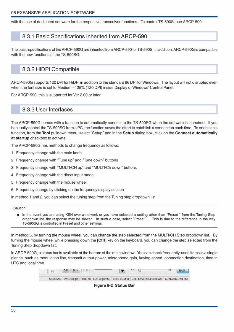
08 EXPANSIVE APPLICATION SOFTWARE
58
with the use of dedicated software for the respective transceiver functions. To control TS-590S, use ARCP-590.
8.3.1 Basic Specifications Inherited from ARCP-590
The basic specifications of the ARCP-590G are inherited from ARCP-590 for TS-590S. In addition, ARCP-590G is compatible
with the new functions of the TS-590SG.
8.3.2 HiDPI Compatible
ARCP-590G supports 120 DPI for HiDPI in addition to the standard 96 DPI for Windows. The layout will not disrupted even
when the font size is set to Medium - 125% (120 DPI) inside Display of Windows' Control Panel.
For ARCP-590, this is supported for Ver 2.00 or later.
8.3.3 User Interfaces
The ARCP-590G comes with a function to automatically connect to the TS-590SG when the software is launched. If you
habitually control the TS-590SG from a PC, the function saves the effort to establish a connection each time. To enable this
function, from the Tool pulldown menu, select “Setup” and in the Setup dialog box, click on the Connect automatically
at startup checkbox to activate.
The ARCP-590G has methods to change frequency as follows:
1. Frequency change with the main knob
2. Frequency change with “Tune up” and “Tune down” buttons
3. Frequency change with “MULTI/CH up” and “MULTI/Ch down” buttons
4. Frequency change with the direct input mode
5. Frequency change with the mouse wheel
6. Frequency change by clicking on the frequency display section
In method 1 and 2, you can select the tuning step from the Tuning step dropdown list.
Caution:
◆ In the event you are using KSN over a network or you have selected a setting other than “Preset ” from the Tuning Step
dropdown list, the response may be slower. In such a case, select “Preset” . This is due to the difference in the way
TS-590SG is controlled in Preset and other settings.
In method 5, by turning the mouse wheel, you can change the step selected from the MULTI/CH Step dropdown list. By
turning the mouse wheel while pressing down the [Ctrl] key on the keyboard, you can change the step selected from the
Tuning Step dropdown list.
In ARCP-590G, a status bar is available at the bottom of the main window. You can check frequently-used items in a single
glance, such as modulation line, transmit output power, microphone gain, keying speed, connection destination, time in
UTC and local time.
Figure 8-2 Status Bar
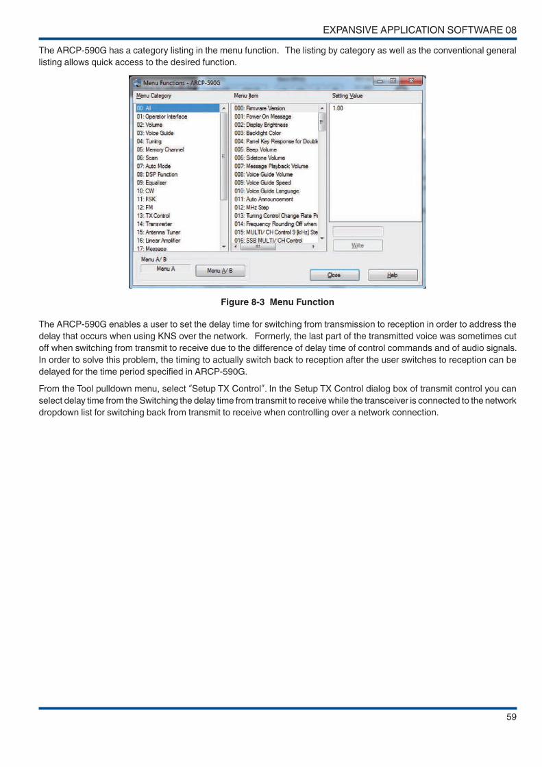
EXPANSIVE APPLICATION SOFTWARE 08
59
The ARCP-590G has a category listing in the menu function. The listing by category as well as the conventional general
listing allows quick access to the desired function.
Figure 8-3 Menu Function
The ARCP-590G enables a user to set the delay time for switching from transmission to reception in order to address the
delay that occurs when using KNS over the network. Formerly, the last part of the transmitted voice was sometimes cut
off when switching from transmit to receive due to the difference of delay time of control commands and of audio signals.
In order to solve this problem, the timing to actually switch back to reception after the user switches to reception can be
delayed for the time period specified in ARCP-590G.
From the Tool pulldown menu, select “Setup TX Control”. In the Setup TX Control dialog box of transmit control you can
select delay time from the Switching the delay time from transmit to receive while the transceiver is connected to the network
dropdown list for switching back from transmit to receive when controlling over a network connection.
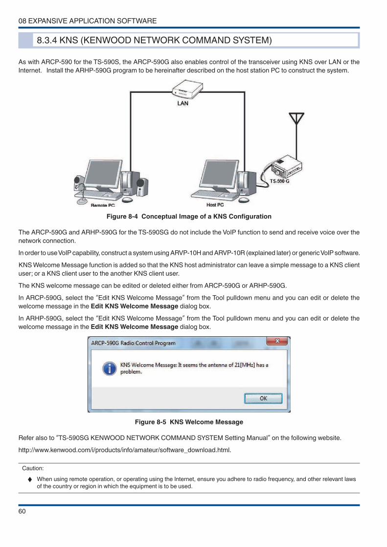
08 EXPANSIVE APPLICATION SOFTWARE
60
8.3.4 KNS (KENWOOD NETWORK COMMAND SYSTEM)
As with ARCP-590 for the TS-590S, the ARCP-590G also enables control of the transceiver using KNS over LAN or the
Internet. Install the ARHP-590G program to be hereinafter described on the host station PC to construct the system.
Figure 8-4 Conceptual Image of a KNS Configuration
The ARCP-590G and ARHP-590G for the TS-590SG do not include the VoIP function to send and receive voice over the
network connection.
In order to use VoIP capability, construct a system using ARVP-10H and ARVP-10R (explained later) or generic VoIP software.
KNS Welcome Message function is added so that the KNS host administrator can leave a simple message to a KNS client
user; or a KNS client user to the another KNS client user.
The KNS welcome message can be edited or deleted either from ARCP-590G or ARHP-590G.
In ARCP-590G, select the “Edit KNS Welcome Message” from the Tool pulldown menu and you can edit or delete the
welcome message in the Edit KNS Welcome Message dialog box.
In ARHP-590G, select the “Edit KNS Welcome Message” from the Tool pulldown menu and you can edit or delete the
welcome message in the Edit KNS Welcome Message dialog box.
Figure 8-5 KNS Welcome Message
Refer also to “TS-590SG KENWOOD NETWORK COMMAND SYSTEM Setting Manual” on the following website.
http://www.kenwood.com/i/products/info/amateur/software_download.html.
Caution:
◆ When using remote operation, or operating using the Internet, ensure you adhere to radio frequency, and other relevant laws
of the country or region in which the equipment is to be used.

EXPANSIVE APPLICATION SOFTWARE 08
61
8.3.5 Visual Scan
ARCP-590G is capable of visually showing the location of the current RX frequency on the display and shifting the current
RX frequency to the center of the scan span. The scan center frequency and the scan span can be stored for each amateur
radio band. It is ideal for checking the condition of respective bands for specified frequency ranges.
Figure 8-6 Visual Scan
Note:
◆ During the scan, the receive audio of the transceiver is muted.
8.3.6 Audio Equalizer
In ARCP-590G, the setting of the audio filter can be configured with a graphic equalizer-type interface. ARCP-590G has
18 bands from 0 Hz through 5,100 kHz.
Figure 8-7 Audio Equalizer

08 EXPANSIVE APPLICATION SOFTWARE
62
8.3.7 Tuning the Split Transmit Frequency
ARCP-590G supports the new split transmit frequency method (kHz UP/DOWN) adopted by ARCP-990.
Figure 8-8 Tuning the Split Transmit Frequency
This function is also available for use on ARCP-590 Ver 2.00 or later (TS-590S firmware version 2.00 or later is required).
8.3.8 Function Key Setting
ARCP-590G supports function key setting for all menu items. You can assign all the functions available in the main screen
menu to the function keys.
For ARCP-590, this is supported for Ver 2.00 or later.
8.3.9 Morse Code Decoder
ARCP-590G supports the Morse code decoder function supported by TS-590SG. For ARCP-590G, you can make use of
the screen size of Windows to display more lines.
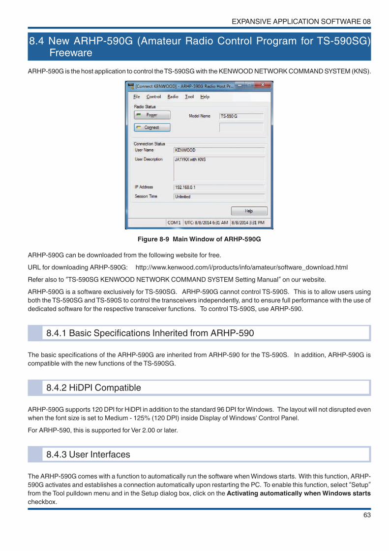
EXPANSIVE APPLICATION SOFTWARE 08
63
8.4 New ARHP-590G (Amateur Radio Control Program for TS-590SG) Freeware
ARHP-590G is the host application to control the TS-590SG with the KENWOOD NETWORK COMMAND SYSTEM (KNS).
Figure 8-9 Main Window of ARHP-590G
ARHP-590G can be downloaded from the following website for free.
URL for downloading ARHP-590G: http://www.kenwood.com/i/products/info/amateur/software_download.html
Refer also to “TS-590SG KENWOOD NETWORK COMMAND SYSTEM Setting Manual” on our website.
ARHP-590G is a software exclusively for TS-590SG. ARHP-590G cannot control TS-590S. This is to allow users using
both the TS-590SG and TS-590S to control the transceivers independently, and to ensure full performance with the use of
dedicated software for the respective transceiver functions. To control TS-590S, use ARHP-590.
8.4.1 Basic Specifications Inherited from ARHP-590
The basic specifications of the ARHP-590G are inherited from ARHP-590 for the TS-590S. In addition, ARHP-590G is
compatible with the new functions of the TS-590SG.
8.4.2 HiDPI Compatible
ARHP-590G supports 120 DPI for HiDPI in addition to the standard 96 DPI for Windows. The layout will not disrupted even
when the font size is set to Medium - 125% (120 DPI) inside Display of Windows' Control Panel.
For ARHP-590, this is supported for Ver 2.00 or later.
8.4.3 User Interfaces
The ARHP-590G comes with a function to automatically run the software when Windows starts. With this function, ARHP-
590G activates and establishes a connection automatically upon restarting the PC. To enable this function, select “Setup” from the Tool pulldown menu and in the Setup dialog box, click on the Activating automatically when Windows starts
checkbox.

08 EXPANSIVE APPLICATION SOFTWARE
64
8.4.4 KNS (KENWOOD NETWORK COMMAND SYSTEM)
For details, refer to 8.3.4. KNS (KENWOOD NETWORK COMMAND SYSTEM).
8.4.5 Disabling AF Gain Control from ARCP-590G
ARHP-590G can disable the AF gain control from the ARCP-590G. When AF gain is controlled from the ARCP-590G, the
sound level of the TS-590SG may be adjusted unexpectedly. However, there is a function to disable this control.
To enable this function, select “Setup” from the Tool pulldown menu and click on the Prohibits control of AF gain from
ARCP-590G checkbox in the Setup dialog box. In the Other tab, click on the Run automatically at Windows startup checkbox.
8.5 ARUA-10 (USB Audio Controller) Freeware
We have released ARUA-10, a USB audio control software, which allows the microphone and speaker of a PC to be used
in place those of the TS-590SG.
ARUA-10 is available free and can be downloaded from the following website.
URL from which ARUA-10 can be downloaded:
http://www.kenwood.com/i/products/info/amateur/software_download.html
Refer also to “TS-590SG USB Audio Setting Manual” on the website.
Caution:
◆ For USB audio, time delay is unavoidable due to its operating principle. Therefore, USB audio cannot be used for a latency-
critical application (e.g. operations in a contest or pileup where a quick response is essential).
◆ During the operation with KNS over a network connection, ARUA-10 is not required.
8.5.1 Basic Functions
If ARUA-10 and ARCP-590G are used in combination, you can use the microphone and speaker connected to the PC in
place of those on the transceiver simply by connecting TS-590SG and the PC with a USB cable. To use ARCP-590G over
the USB cable connection, a virtual COM port driver needs to be installed.
If you use only ARUA-10 over a USB cable connection, the virtual port driver doesn’t need to be installed. If you are using
only the built-in USB sound function of the TS-590SG, the function runs on the standard driver of Windows.
8.5.2 Operation
ARUA-10 bridges the built-in USB sound function (USB audio device) of TS-590SG and the sound device that controls the
microphone and speaker on the PC.
The audio input signal from the microphone of the PC is input to the modulation input of the USB audio device of TS-590SG.
The audio output from the USB audio device of TS-590SG is output from the speaker of the PC.

EXPANSIVE APPLICATION SOFTWARE 08
65
Figure 8-10 Flow of the Audio Signal
8.5.3 Setup
Configure the necessary settings to use ARUA-10.
Right click the “ARUA-10” icon in the Windows task tray and select “Device Setup” in the menu and the Setup dialog box
will appear. In the Device tab, you can set up the device to input/output the audio signal.
Figure 8-11 Device Tab
In the “Reception Output” of the Transceiver frame, “Microphone (USB Audio CODEC)” must be selected.
In the “Modulation Input” of the Transceiver frame, “Speaker (USB Audio CODEC)” must be selected.
In the “Microphone” of the PC frame, specify the microphone of the sound device.
In the “Speakers” of the PC frame, specify the speaker of the sound device.
You can check the name of the sound device in the entry under “Sound video and game controllers” category in Windows
Device Manager.
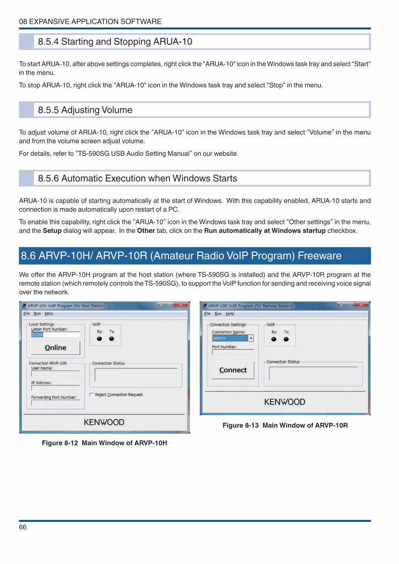
08 EXPANSIVE APPLICATION SOFTWARE
66
8.5.4 Starting and Stopping ARUA-10
To start ARUA-10, after above settings completes, right click the "ARUA-10" icon in the Windows task tray and select "Start"
in the menu.
To stop ARUA-10, right click the "ARUA-10" icon in the Windows task tray and select "Stop" in the menu.
8.5.5 Adjusting Volume
To adjust volume of ARUA-10, right click the “ARUA-10” icon in the Windows task tray and select “Volume” in the menu
and from the volume screen adjust volume.
For details, refer to “TS-590SG USB Audio Setting Manual” on our website.
8.5.6 Automatic Execution when Windows Starts
ARUA-10 is capable of starting automatically at the start of Windows. With this capability enabled, ARUA-10 starts and
connection is made automatically upon restart of a PC.
To enable this capability, right click the “ARUA-10” icon in the Windows task tray and select “Other settings” in the menu,
and the Setup dialog will appear. In the Other tab, click on the Run automatically at Windows startup checkbox.
8.6 ARVP-10H/ ARVP-10R (Amateur Radio VoIP Program) Freeware
We offer the ARVP-10H program at the host station (where TS-590SG is installed) and the ARVP-10R program at the
remote station (which remotely controls the TS-590SG), to support the VoIP function for sending and receiving voice signal
over the network.
Figure 8-12 Main Window of ARVP-10H
Figure 8-13 Main Window of ARVP-10R

EXPANSIVE APPLICATION SOFTWARE 08
67
ARVP-10H and ARVP-10R are available free and can be downloaded from the following website.
URL from which ARVP-10H and ARVP-10R can be downloaded:
http://www.kenwood.com/i/products/info/amateur/software_download.html
Refer also to “TS-590SG KENWOOD NETWORK COMMAND SYSTEM Setting Manual” on the website.
8.6.1 Basic Functions
ARVP-10H and ARVP-10R enable a voice signal to be sent and received over LAN or the Internet.
8.6.2 Setup of ARVP-10H (Host Station)
Configure the necessary settings to use ARVP-10H.
Select “User Settings” from the File pulldown menu and click the “Add...” button in the User Settings dialog box and the
Setup User dialog box will appear. In Setup User dialog box, you can set the user name and password.
Figure 8-14 Setup User Dialog Box (ARVP-10H)
To disable the user temporarily, click on the User is disabled checkbox.
To deny a connection request from all users temporarily, click on the Reject connection request checkbox in the main
window.
8.6.3 Making ARVP-10H (host station) Online or Offline
To place ARVP-10H online, after above setting is complete, click the “Online” button in the main window.
To take ARVP-10H offline, click the “Offline” button in the main window.
8.6.4 Setup of ARVP-10R (Remote Station)
Configure the necessary settings to use ARVP-10R.
Select “User Settings” from the File pulldown menu and click the “Add...” button in the User Settings dialog box and the
Setup User dialog box will appear. In Detailed Settings dialog box, you can set the connection name, IP address, the
port number, user name and password.
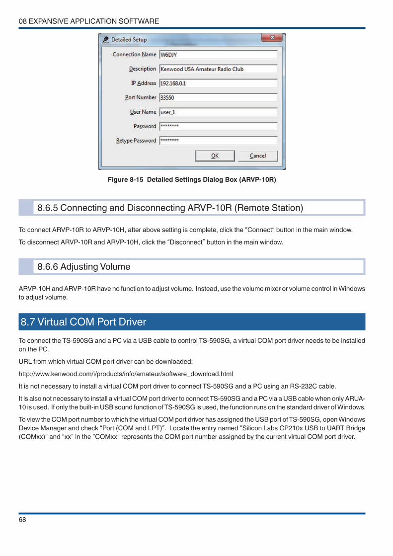
08 EXPANSIVE APPLICATION SOFTWARE
68
Figure 8-15 Detailed Settings Dialog Box (ARVP-10R)
8.6.5 Connecting and Disconnecting ARVP-10R (Remote Station)
To connect ARVP-10R to ARVP-10H, after above setting is complete, click the “Connect” button in the main window.
To disconnect ARVP-10R and ARVP-10H, click the “Disconnect” button in the main window.
8.6.6 Adjusting Volume
ARVP-10H and ARVP-10R have no function to adjust volume. Instead, use the volume mixer or volume control in Windows
to adjust volume.
8.7 Virtual COM Port Driver
To connect the TS-590SG and a PC via a USB cable to control TS-590SG, a virtual COM port driver needs to be installed
on the PC.
URL from which virtual COM port driver can be downloaded:
http://www.kenwood.com/i/products/info/amateur/software_download.html
It is not necessary to install a virtual COM port driver to connect TS-590SG and a PC using an RS-232C cable.
It is also not necessary to install a virtual COM port driver to connect TS-590SG and a PC via a USB cable when only ARUA-
10 is used. If only the built-in USB sound function of TS-590SG is used, the function runs on the standard driver of Windows.
To view the COM port number to which the virtual COM port driver has assigned the USB port of TS-590SG, open Windows
Device Manager and check “Port (COM and LPT)”. Locate the entry named “Silicon Labs CP210x USB to UART Bridge
(COMxx)” and “xx” in the “COMxx” represents the COM port number assigned by the current virtual COM port driver.
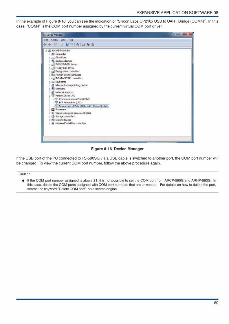
EXPANSIVE APPLICATION SOFTWARE 08
69
In the example of Figure 8-16, you can see the indication of “Silicon Labs CP210x USB to UART Bridge (COM4)”. In this
case, “COM4” is the COM port number assigned by the current virtual COM port driver.
Figure 8-16 Device Manager
If the USB port of the PC connected to TS-590SG via a USB cable is switched to another port, the COM port number will
be changed. To view the current COM port number, follow the above procedure again.
Caution:
◆ If the COM port number assigned is above 21, it is not possible to set the COM port from ARCP-590G and ARHP-590G. In
this case, delete the COM ports assigned with COM port numbers that are unwanted. For details on how to delete the port,
search the keyword “Delete COM port” on a search engine.
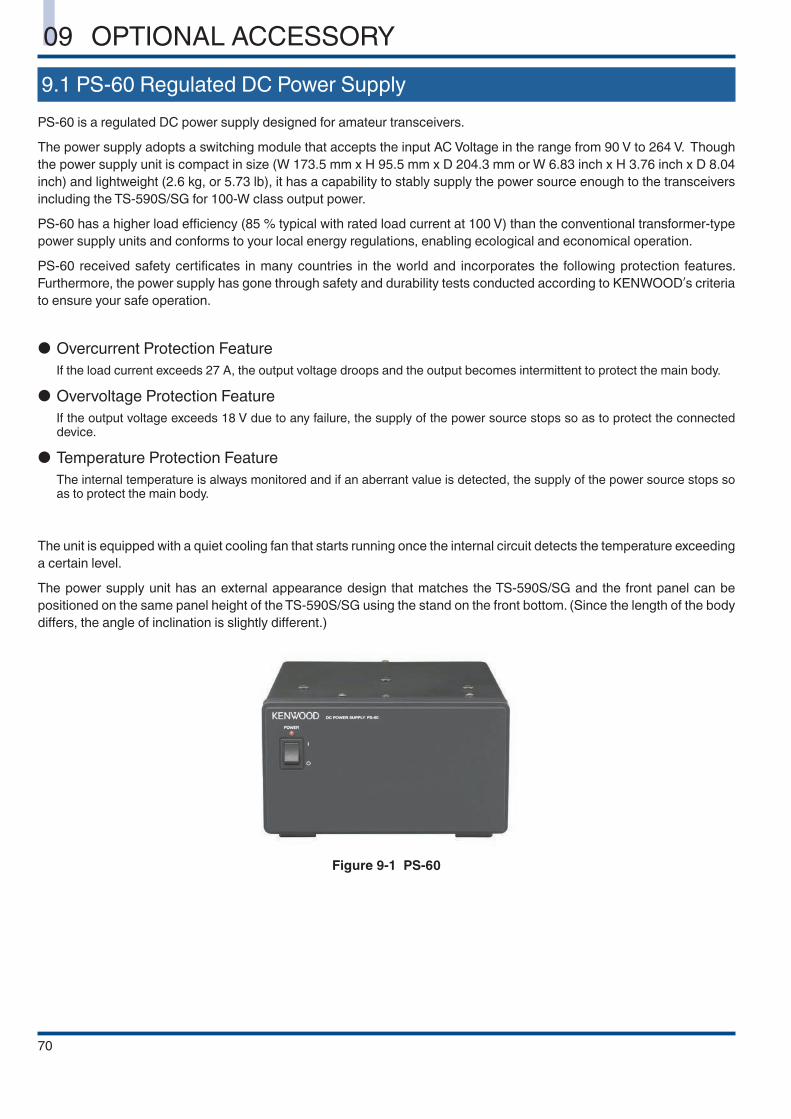
70
09 OPTIONAL ACCESSORY
9.1 PS-60 Regulated DC Power Supply
PS-60 is a regulated DC power supply designed for amateur transceivers.
The power supply adopts a switching module that accepts the input AC Voltage in the range from 90 V to 264 V. Though
the power supply unit is compact in size (W 173.5 mm x H 95.5 mm x D 204.3 mm or W 6.83 inch x H 3.76 inch x D 8.04
inch) and lightweight (2.6 kg, or 5.73 lb), it has a capability to stably supply the power source enough to the transceivers
including the TS-590S/SG for 100-W class output power.
PS-60 has a higher load efficiency (85 % typical with rated load current at 100 V) than the conventional transformer-type
power supply units and conforms to your local energy regulations, enabling ecological and economical operation.
PS-60 received safety certificates in many countries in the world and incorporates the following protection features.
Furthermore, the power supply has gone through safety and durability tests conducted according to KENWOOD’s criteria
to ensure your safe operation.
● Overcurrent Protection Feature
If the load current exceeds 27 A, the output voltage droops and the output becomes intermittent to protect the main body.
● Overvoltage Protection Feature
If the output voltage exceeds 18 V due to any failure, the supply of the power source stops so as to protect the connected device.
● Temperature Protection Feature
The internal temperature is always monitored and if an aberrant value is detected, the supply of the power source stops so as to protect the main body.
The unit is equipped with a quiet cooling fan that starts running once the internal circuit detects the temperature exceeding
a certain level.
The power supply unit has an external appearance design that matches the TS-590S/SG and the front panel can be
positioned on the same panel height of the TS-590S/SG using the stand on the front bottom. (Since the length of the body
differs, the angle of inclination is slightly different.)
Figure 9-1 PS-60
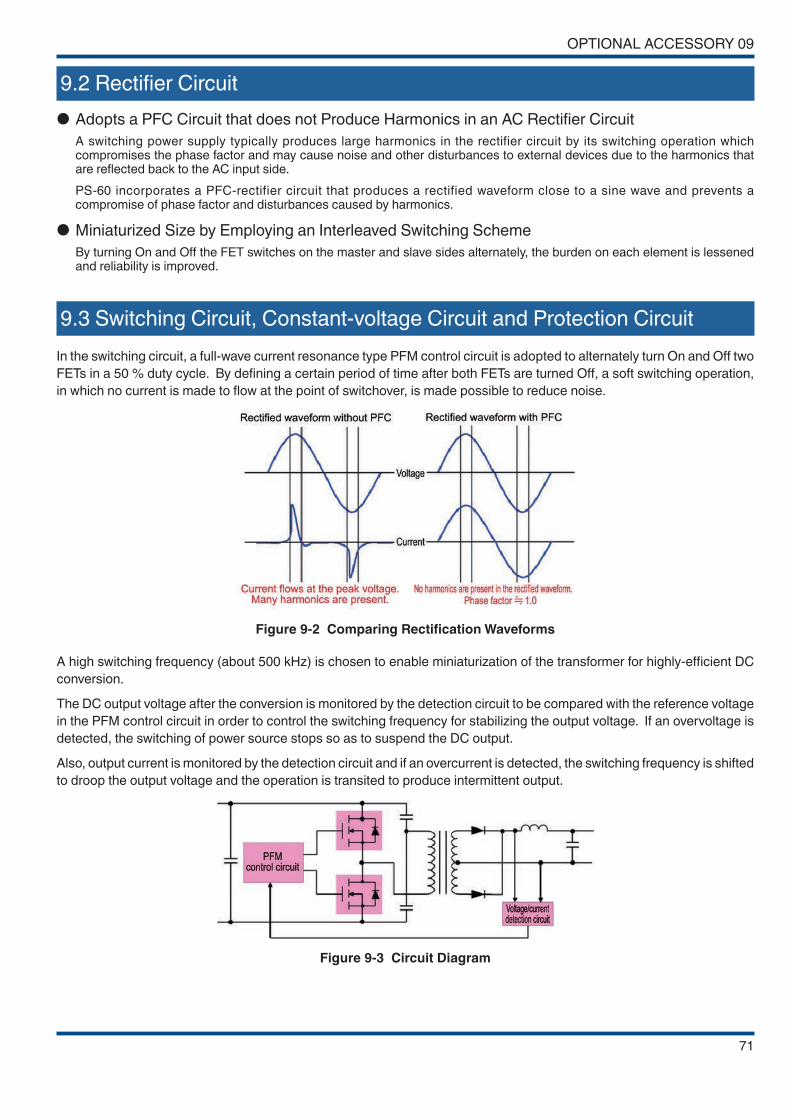
OPTIONAL ACCESSORY 09
71
9.2 Rectifier Circuit
● Adopts a PFC Circuit that does not Produce Harmonics in an AC Rectifier Circuit
A switching power supply typically produces large harmonics in the rectifier circuit by its switching operation which compromises the phase factor and may cause noise and other disturbances to external devices due to the harmonics that are reflected back to the AC input side.
PS-60 incorporates a PFC-rectifier circuit that produces a rectified waveform close to a sine wave and prevents a compromise of phase factor and disturbances caused by harmonics.
● Miniaturized Size by Employing an Interleaved Switching Scheme
By turning On and Off the FET switches on the master and slave sides alternately, the burden on each element is lessened and reliability is improved.
9.3 Switching Circuit, Constant-voltage Circuit and Protection Circuit
In the switching circuit, a full-wave current resonance type PFM control circuit is adopted to alternately turn On and Off two
FETs in a 50 % duty cycle. By defining a certain period of time after both FETs are turned Off, a soft switching operation,
in which no current is made to flow at the point of switchover, is made possible to reduce noise.
Figure 9-2 Comparing Rectification Waveforms
A high switching frequency (about 500 kHz) is chosen to enable miniaturization of the transformer for highly-efficient DC
conversion.
The DC output voltage after the conversion is monitored by the detection circuit to be compared with the reference voltage
in the PFM control circuit in order to control the switching frequency for stabilizing the output voltage. If an overvoltage is
detected, the switching of power source stops so as to suspend the DC output.
Also, output current is monitored by the detection circuit and if an overcurrent is detected, the switching frequency is shifted
to droop the output voltage and the operation is transited to produce intermittent output.
Figure 9-3 Circuit Diagram

TS-590SG In-depth Manual
May 12, 2015
© 2015
All Rights Reserved.
CA-330W-E76