abp04300 english
DESCRIPTION
ABP04300 EnglishCAN BUS utilityTRANSCRIPT
9
EN
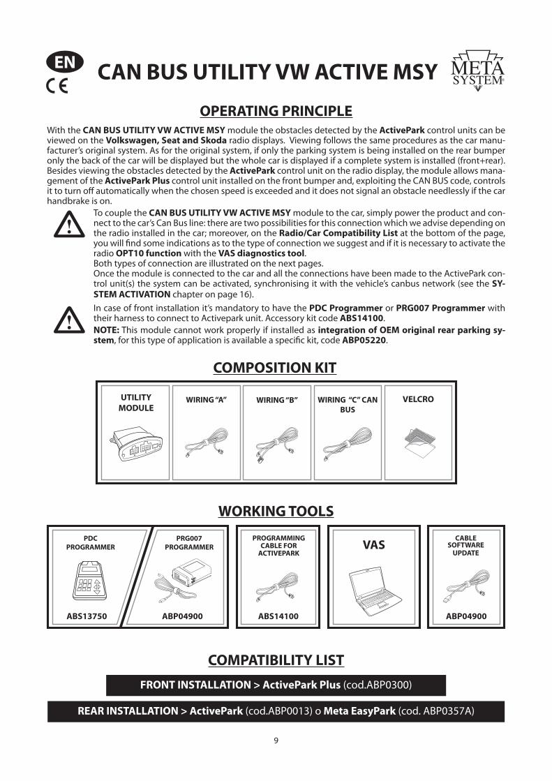
OPERATING PRINCIPLEWith the CAN BUS UTILITY VW ACTIVE MSY module the obstacles detected by the ActivePark control units can be viewed on the Volkswagen, Seat and Skoda radio displays. Viewing follows the same procedures as the car manu-facturer’s original system. As for the original system, if only the parking system is being installed on the rear bumper only the back of the car will be displayed but the whole car is displayed if a complete system is installed (front+rear). Besides viewing the obstacles detected by the ActivePark control unit on the radio display, the module allows mana-gement of the ActivePark Plus control unit installed on the front bumper and, exploiting the CAN BUS code, controls it to turn off automatically when the chosen speed is exceeded and it does not signal an obstacle needlessly if the car handbrake is on.
To couple the CAN BUS UTILITY VW ACTIVE MSY module to the car, simply power the product and con-nect to the car’s Can Bus line: there are two possibilities for this connection which we advise depending on the radio installed in the car; moreover, on the Radio/Car Compatibility List at the bottom of the page, you will fi nd some indications as to the type of connection we suggest and if it is necessary to activate the radio OPT10 function with the VAS diagnostics tool.Both types of connection are illustrated on the next pages.Once the module is connected to the car and all the connections have been made to the ActivePark con-trol unit(s) the system can be activated, synchronising it with the vehicle’s canbus network (see the SY-STEM ACTIVATION chapter on page 16).
In case of front installation it’s mandatory to have the PDC Programmer or PRG007 Programmer with their harness to connect to Activepark unit. Accessory kit code ABS14100.
NOTE: This module cannot work properly if installed as integration of OEM original rear parking sy-stem, for this type of application is available a specifi c kit, code ABP05220.
COMPOSITION KIT
UTILITYMODULE
WIRING “A” WIRING “B” WIRING “C” CAN BUS
VELCRO
CAN BUS UTILITY VW ACTIVE MSY
COMPATIBILITY LISTFRONT INSTALLATION > ActivePark Plus (cod.ABP0300)
REAR INSTALLATION > ActivePark (cod.ABP0013) o Meta EasyPark (cod. ABP0357A)
ABP04900
CABLESOFTWARE
UPDATE
WORKING TOOLS
VAS
ABS14100
PROGRAMMINGCABLE FOR
ACTIVEPARK
ABP04900
PRG007PROGRAMMER
ABS13750
PDCPROGRAMMER
10
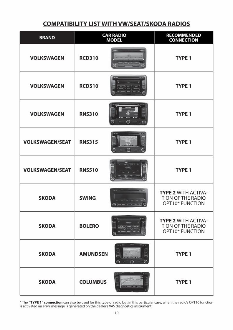
COMPATIBILITY LIST WITH VW/SEAT/SKODA RADIOS
BRAND CAR RADIOMODEL
RECOMMENDEDCONNECTION
VOLKSWAGEN RCD310 TYPE 1
VOLKSWAGEN RCD510 TYPE 1
VOLKSWAGEN RNS310 TYPE 1
VOLKSWAGEN/SEAT RNS315 TYPE 1
VOLKSWAGEN/SEAT RNS510 TYPE 1
SKODA SWINGTYPE 2 WITH ACTIVA-TION OF THE RADIO OPT10* FUNCTION
SKODA BOLEROTYPE 2 WITH ACTIVA-TION OF THE RADIO OPT10* FUNCTION
SKODA AMUNDSEN TYPE 1
SKODA COLUMBUS TYPE 1
* The “TYPE 1” connection can also be used for this type of radio but in this particular case, when the radio’s OPT10 function is activated an error message is generated on the dealer’s VAS diagnostics instrument.
11
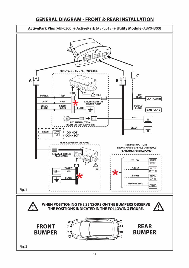
Fig. 2
REARBUMPER
FRONTBUMPER
WHEN POSITIONING THE SENSORS ON THE BUMPERS OBSERVETHE POSITIONS INDICATED IN THE FOLLOWING FIGURE.
GENERAL DIAGRAM - FRONT & REAR INSTALLATION
Fig. 1
ActivePark Plus (ABP0300) + ActivePark (ABP0013) + Utility Module (ABP04300)
FRONT ActivePark Plus (ABP0300)
REAR ActivePark (ABP0013)
ActivePark DISPLAYREAR SYSTEM
ActivePark DISPLAYFRONT SYSTEM
LED PUSH BUTTONFRONT SYSTEM ActivePark
ORANGE
RED
BLACK
GREY
GREEN/BLACK
RED/BLACK
PURPLE/BLACK
RED
BLACK
SENSITIVITYREDUCTION
DECREASE OFSYSTEM
PERFORMANCE
RED/DARK BLUE
BROWN
PURPLE
YELLOW
SEE INSTRUCTIONSFRONT ActivePark Plus (ABP0300)
REAR ActivePark (ABP0013)
BLACK
RED
GREY
GREEN/BLACK
DO NOTCONNECT
Fig.2
Fig.2YELLOW
GREEN
12
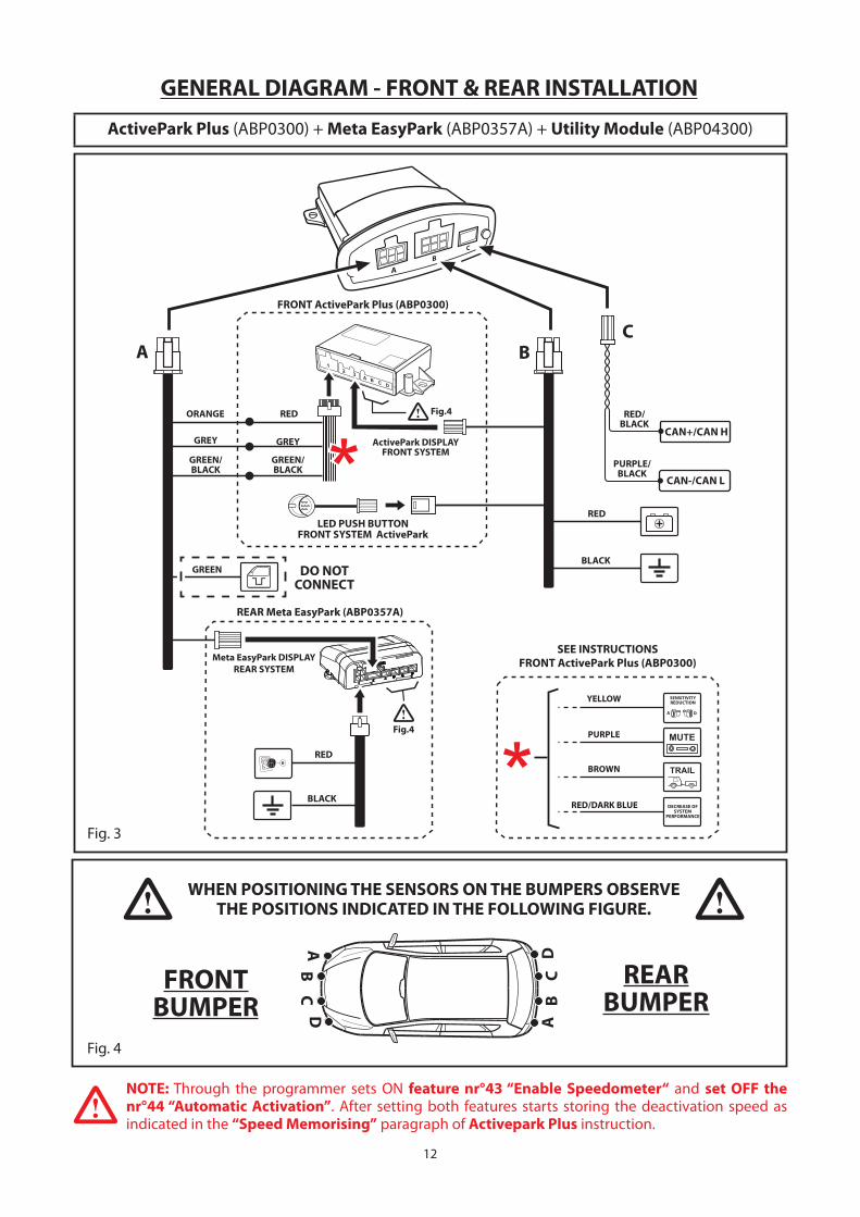
Fig. 4
REARBUMPER
FRONTBUMPER
WHEN POSITIONING THE SENSORS ON THE BUMPERS OBSERVETHE POSITIONS INDICATED IN THE FOLLOWING FIGURE.
GENERAL DIAGRAM - FRONT & REAR INSTALLATION
ActivePark Plus (ABP0300) + Meta EasyPark (ABP0357A) + Utility Module (ABP04300)
Fig. 3
FRONT ActivePark Plus (ABP0300)
Meta EasyPark DISPLAYREAR SYSTEM
ActivePark DISPLAYFRONT SYSTEM
LED PUSH BUTTONFRONT SYSTEM ActivePark
RED
BLACKGREEN
RED/BLACK
PURPLE/BLACK
RED
BLACK
SENSITIVITYREDUCTION
DECREASE OFSYSTEM
PERFORMANCE
RED/DARK BLUE
BROWN
PURPLE
YELLOW
SEE INSTRUCTIONSFRONT ActivePark Plus (ABP0300)
Fig.4
Fig.4
REAR Meta EasyPark (ABP0357A)
ORANGE
GREY
GREEN/BLACK
RED
GREY
GREEN/BLACK
DO NOTCONNECT
NOTE: Through the programmer sets ON feature nr°43 “Enable Speedometer“ and set OFF the nr°44 “Automatic Activation”. After setting both features starts storing the deactivation speed as
indicated in the “Speed Memorising” paragraph of Activepark Plus instruction.
13
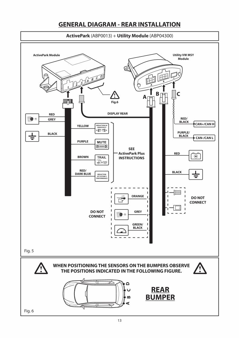
Fig. 6
REARBUMPER
WHEN POSITIONING THE SENSORS ON THE BUMPERS OBSERVETHE POSITIONS INDICATED IN THE FOLLOWING FIGURE.
GENERAL DIAGRAM - REAR INSTALLATION
ActivePark (ABP0013) + Utility Module (ABP04300)
Fig. 5
Utility VW MSYModule
ActivePark Module
DO NOTCONNECT
DO NOTCONNECT
SEEActivePark PlusINSTRUCTIONS
RED
BLACK
GREY
RED
BLACK
RED/BLACK
PURPLE/BLACK
REDUCTION OFSENSITIVITY
REDUCTIONOF SYSTEM’S
PERFORMANCE
GREEN/BLACK
GREY
ORANGE
RED/DARK BLUE
BROWN
PURPLE
YELLOW
Fig.6
DISPLAY REAR
14
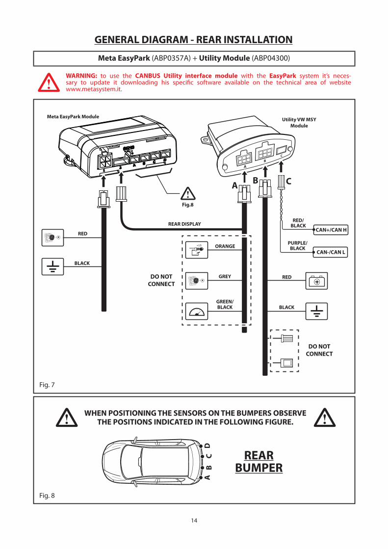
Fig. 8
REARBUMPER
WHEN POSITIONING THE SENSORS ON THE BUMPERS OBSERVETHE POSITIONS INDICATED IN THE FOLLOWING FIGURE.
GENERAL DIAGRAM - REAR INSTALLATION
Meta EasyPark (ABP0357A) + Utility Module (ABP04300)
Fig. 7
REAR DISPLAY
RED
BLACK
ORANGE
GREY
GREEN/BLACK
RED
BLACK
RED/BLACK
PURPLE/BLACK
Utility VW MSYModule
Meta EasyPark Module
DO NOTCONNECT
Fig.8
DO NOTCONNECT
WARNING: to use the CANBUS Utility interface module with the EasyPark system it’s neces-sary to update it downloading his specifi c software available on the technical area of websitewww.metasystem.it.
15
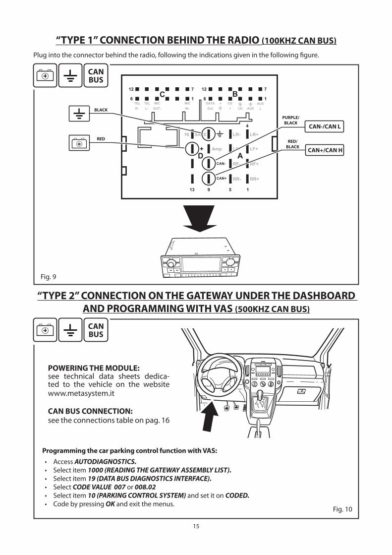
“TYPE 1” CONNECTION BEHIND THE RADIO (100KHZ CAN BUS)Plug into the connector behind the radio, following the indications given in the following fi gure.
“TYPE 2” CONNECTION ON THE GATEWAY UNDER THE DASHBOARD AND PROGRAMMING WITH VAS (500KHZ CAN BUS)
Fig. 9
POWERING THE MODULE:see technical data sheets dedica-ted to the vehicle on the website
www.metasystem.it
CAN BUS CONNECTION:see the connections table on pag. 16
Programming the car parking control function with VAS:• Access AUTODIAGNOSTICS.• Select item 1000 (READING THE GATEWAY ASSEMBLY LIST).• Select item 19 (DATA BUS DIAGNOSTICS INTERFACE).• Select CODE VALUE 007 or 008.02• Select item 10 (PARKING CONTROL SYSTEM) and set it on CODED.• Code by pressing OK and exit the menus.
BLACK
RED
PURPLE/BLACK
RED/BLACK
Fig. 10
16
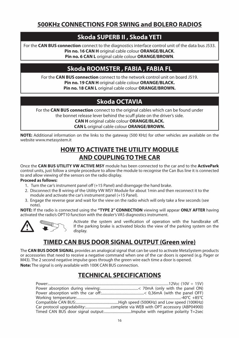
HOW TO ACTIVATE THE UTILITY MODULEAND COUPLING TO THE CAR
Once the CAN BUS UTILITY VW ACTIVE MSY module has been connected to the car and to the ActivePark control units, just follow a simple procedure to allow the module to recognise the Can Bus line it is connected to and allow viewing of the sensors on the radio display.
Proceed as follows:1. Turn the car’s instrument panel off (+15 Panel) and disengage the hand brake.
2. Disconnect the B wiring of the Utility VW MSY Module for about 1min and then reconnect it to the module and activate the car’s instrument panel (+15 Panel).
3. Engage the reverse gear and wait for the view on the radio which will only take a few seconds (see note).
NOTE: If the radio is connected using the “TYPE 2” CONNECTION viewing will appear ONLY AFTER having activated the radio’s OPT10 function with the dealer’s VAS diagnostics instrument.
TIMED CAN BUS DOOR SIGNAL OUTPUT (Green wire)The CAN BUS DOOR SIGNAL provides an analogical signal that can be used to activate MetaSystem products or accessories that need to receive a negative command when one of the car doors is opened (e.g. Pager or M43). The 2 second negative impulse goes through the green wire each time a door is opened.
Note: The signal is only available with 100K CAN BUS connection.
500KHz CONNECTIONS FOR SWING and BOLERO RADIOS
Skoda SUPERB II , Skoda YETIFor the CAN BUS connection connect to the diagnostics interface control unit of the data bus J533.
Pin no. 16 CAN H original cable colour ORANGE/BLACK.
Pin no. 6 CAN L original cable colour ORANGE/BROWN.
Skoda ROOMSTER , FABIA , FABIA FLFor the CAN BUS connection connect to the network control unit on board J519.
Pin no. 19 CAN H original cable colour ORANGE/BLACK.Pin no. 18 CAN L original cable colour ORANGE/BROWN.
Skoda OCTAVIAFor the CAN BUS connection connect to the original cables which can be found under
the bonnet release lever behind the scuff plate on the driver’s side.
CAN H original cable colour ORANGE/BLACK.CAN L original cable colour ORANGE/BROWN.
Activate the system and verifi cation of operation with the handbrake off .If the parking brake is activated blocks the view of the parking system on the display.
NOTE: Additional information on the links to the gateway (500 KHz) for other vehicles are available on the website www.metasystem.it
TECHNICAL SPECIFICATIONSPower:.....................................................................................................................................12Vcc (10V ÷ 15V)Power absorption during viewing:..........................................< 70mA (only with the panel ON)Power absorption with the car off :...............................................< 0,36mA (with the panel OFF)Working temperature:...................................................................................................................-40°C +85°CCompatible CAN BUS:...............................................High speed (500KHz) and Low speed (100KHz)Car protocol upgradability:............................complete via WEB with OPT accessory (ABP04900)Timed CAN BUS door signal output:..............................Impulse with negative polarity T=2sec