abrupt feature extraction via the combination of sparse representations wei wang, wenchao chen,...
TRANSCRIPT

Abrupt Feature Extraction via the Combination of Sparse
Representations
Wei Wang, Wenchao Chen, Jinghuai Gao, Jin XuInstitute of Wave & Information,
Xi’an Jiaotong University
International Symposium on Geophysical Imaging with Localized WavesSanya, Hainan, 24-28 July, 2011
Institute of Wave & Information, Xi'an Jiaotong University, Xi'an, P.R. China

Co-Authors Co-Authors
Wenchao Chen
Jinghuai Gao
Jin Xu

• Introduction
• Morphological Component Analysis
• Abrupt Feature Extraction Methodology
• Synthetic and field data examples
• Conclusions
• Introduction
• Morphological Component Analysis
• Abrupt Feature Extraction Methodology
• Synthetic and field data examples
• Conclusions
Outline Outline

• Problems for stratigraphic interpretation
– Complexity of channels in 3D seismic data always makes detailed interpretation challenging;
– Definition of sand bars and beaches also becomes complicated as they are only partially visible when seismic amplitude is examined.
• How to improve imaging these features
– Current interpretation workflows adopt advanced color and opacity based co-rendering techniques to merge multiple stratigraphic attributes.
IntroductionIntroduction

• Current multi-attributes trap– Instantaneous attributes, e.g., the peak frequency
depicts horizontal distribution of channels and the envelope highlight bright spots and dim spots;
– Coherence attributes are taken to delimit the edges of stratigraphic units;
– Spectral decomposition generates narrow-band instantaneous amplitude volumes and allows better imaging channel details.
Time-consuming to interpret many seismic attributes; Multi-attribute analysis techniques, e.g., multi-attribute 3D visualization, PCA, cluster analysis, sometimes lack explicit physical meaning.

• Motivation
– Raw seismic time samples contain all information represented by various seismic attributes;
– The amplitude and phase spectra and the spatial architecture within an analysis window form specific waveform patterns.
• Our approach
Adopt the morphological component analysis (MCA) theory (Starck, et al., 2005), to extract waveforms of meaningful stratigraphic targets from seismic data;
Different waveform dictionaries are chosen to represent specific waveform patterns by exploring their sparsity.

• Assumptions of the MCA
Firstly, the signal is assumed as a linear combination of different morphological features which are sparsely represented by n different dictionaries:
• Assumptions of the MCA
Firstly, the signal is assumed as a linear combination of different morphological features which are sparsely represented by n different dictionaries:
Morphological Component Analysis
Morphological Component Analysis
1 1
(1)n n
k k kk k
s s
where each signal component can be described as with an overcomplete dictionary and a sparse representation .
k k ks k
k

• Assumptions of the MCA
Secondly, the MCA assumes that for any given component sk the sparsest decomposition over the proper dictionary yields a highly sparse description, while its decomposition over the other dictionaries,
Φj≠k, is highly non sparse, that is
• Sparsity-promoted signal separation
In the MCA framework, the decomposition coefficients of corresponding signal components are the solutions of
0 0
, 1, , ; . (2)T Tk k k jk j n j k s s
k

• Sparsity-promoted signal separation
By substituting the norm by an norm, and relaxing the equality constraint, the MCA algorithm finally seeks a solution by solving the convex minimization problem (Starck, et al., 2005),
• Sparsity-promoted signal separation
By substituting the norm by an norm, and relaxing the equality constraint, the MCA algorithm finally seeks a solution by solving the convex minimization problem (Starck, et al., 2005),
NP-Hard Optimization Problem
10
, , 1 1
Argmin .n
n n
k k kk k
subject to s
0l 1l
1
2
1, , 1 1 2
1Argmin (3)
2n
n nT
k k ks s k k
s s s

• Signal decomposition example• Signal decomposition example
“Bumps+Cosine” Separation
DCT dictionary
Wavelet dictionary

• Signal model assumption
According to morphologic appearance in vertical sections, volumetric flattened seismic data are composed of coherent events and abrupt features;
We thus model these two kinds of seismic features as linear structures and punctate structures respectively. A vertical section s along the inline direction is formulated as
Abrupt Feature Extraction Methodology
Abrupt Feature Extraction Methodology
1 2 n (4)s s s
: abrupt features; : coherent events; n: a zero-mean Gaussian noise matrix with a standard deviation .
1s 2s

• Nonlinear optimization model• Nonlinear optimization model
1 2
2
1 1 1 2 2 2 1 2 21 1,
1Argmin (5)
2T T
s ss s s s s
& : representing dictionaries (s1 & s2); & : controlling how much the sparseness priors are emphasized on the model.
1 2
1 2
The success of MCA relies on the incoherence between sub-dictionaries and each sub-dictionary should lead to sparse representations of thecorresponding signal component.

• Choice of representations
The 2D-UWT presents only three directional elements independent of scales, and there are no highly anisotropic elements. We expect the 2D-UWT to be non-optimal for detection of highly anisotropic features and adopt it to detect punctate features.
• Choice of representations
The 2D-UWT presents only three directional elements independent of scales, and there are no highly anisotropic elements. We expect the 2D-UWT to be non-optimal for detection of highly anisotropic features and adopt it to detect punctate features.
Fig.1 2D-UWT atoms along the horizontal, vertical, and diagonal direction, with three different scale indexes.

• Choice of representations
The curvelet transform is a redundant dictionary and the curvelet elements are anisotropic and obey the parabolic scaling, which makes it the best choice for the detection of anisotropic structures such as coherent wavefronts.
• Choice of representations
The curvelet transform is a redundant dictionary and the curvelet elements are anisotropic and obey the parabolic scaling, which makes it the best choice for the detection of anisotropic structures such as coherent wavefronts.
Fig.2 Discrete curvelets indexed by different scale, orientation, and location.

• Implementation• Implementation
To deal with 3D seismic data, our algorithm is performed line-by-line, each vertical slice separated into abrupt features and coherent events via the iterative-shrinkage algorithm (Bruce et al., 1998; Daubechies et al., 2005):
1) Initialize N, , 11 12 1N 21 22 2N
2) Iterative procedure, n=1,2, …,N,
a) Update x1, assume x2 fixed,
1,1, 1 1, 1, 1 2, 2 1n
Tn n n ns x T x x x
b) Update x2, assume x1 fixed,
2,2, 1 2, 1, 1 1 2, 2 2n
Tn n n ns x T x x x
3) 1 1, 1,Ns x 2 2, 2Ns x

Synthetic data examplesSynthetic data examples
(a) The earth model with a thin channel with the size of 100-m wide and 10-m thick embedded. Both the horizontal and vertical sampled at 2.5-m.
(b) The migrated seismic section is generated by the PSDM algorithm using a Ricker wavelet with dominant frequency 60 Hz.
The reflection waveforms of the channel appear as a bright spot and overlap the coherent reflection events.

Separated synthetic sections by the proposed method: (a) The migrated seismic section of the earth model; (b) The extracted abrupt features part and (c) the coherent events part.

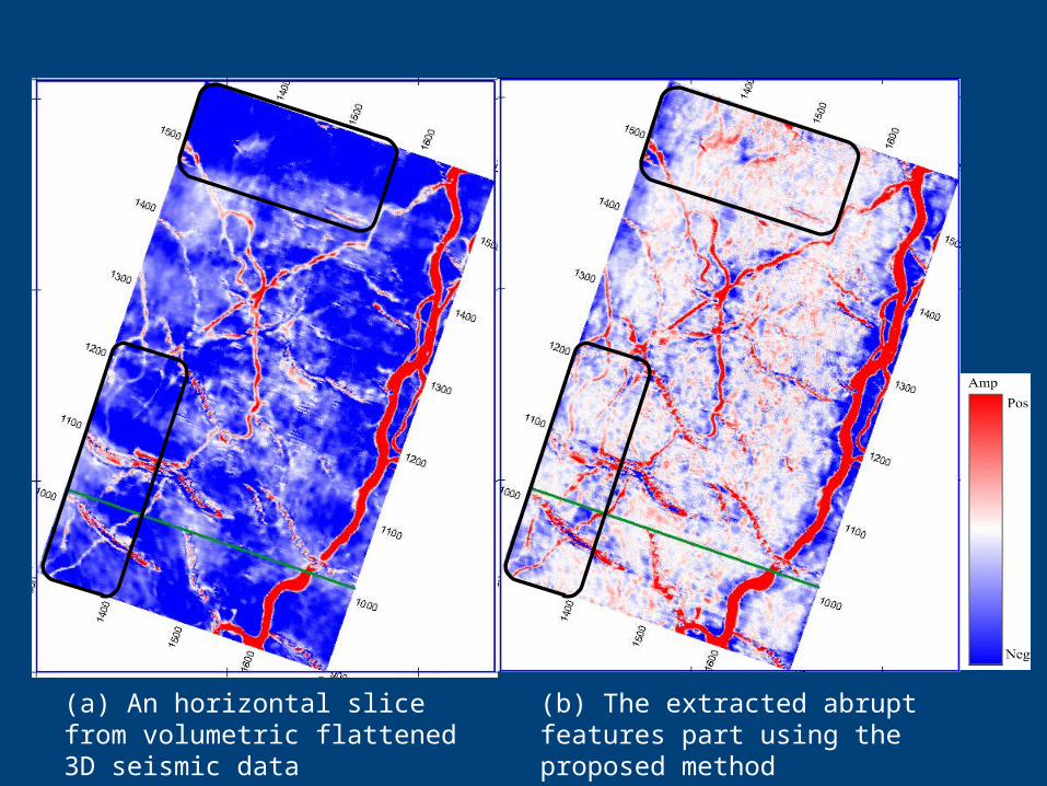
Field data examplesField data examples
(a) An inline section from volumetric flattened 3D seismic data
(b) The separated coherent events part using the proposed method
R
ela
tive G
eolo
gic
al Tim
e (
s)
CMP No. CMP No.
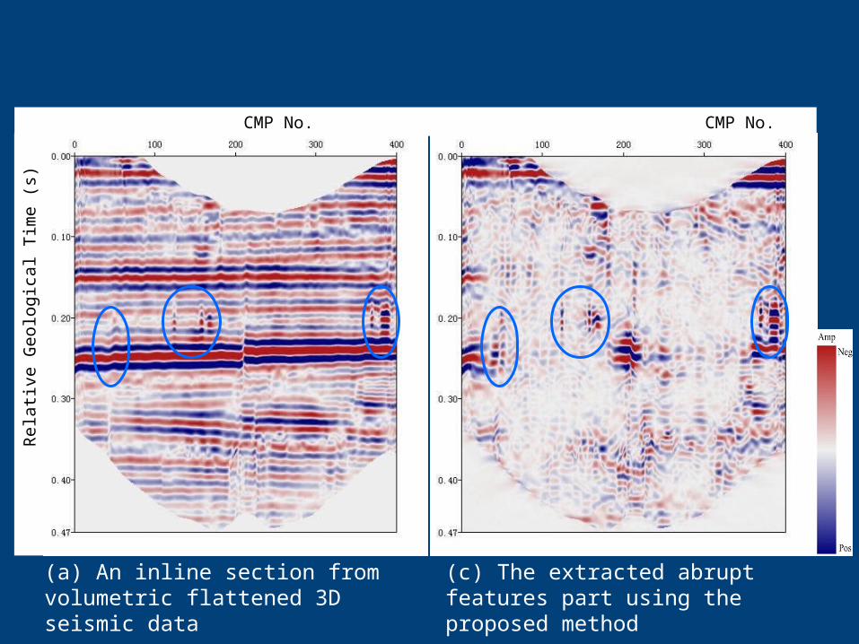
(a) An inline section from volumetric flattened 3D seismic data
(c) The extracted abrupt features part using the proposed method
R
ela
tive G
eolo
gic
al Tim
e (
s)
CMP No. CMP No.

(a) Zoomed part of the inline section
(b) Zoomed part of the coherent events component
(c) Zoomed part of the abrupt features component
Rela
tive G
eolo
gic
al Tim
e (
s)
CMP No. CMP No. CMP No.
Top of Channel
Bottom of Channel
(b) The extracted abrupt features part using the proposed method
(a) An horizontal slice from volumetric flattened 3D seismic data

(a) An horizontal slice from volumetric flattened 3D seismic data
(b) The extracted abrupt features part using the proposed method

The MCA technique is utilized to extract sedimentary features from 3D volumetric flattened seismic data;
Since sedimentary features modeled as punctate structures, the 2D-UWT is chosen to represent the sedimentary features while the curvelet transform, is chosen to sparsify coherent events representation;
Both synthetic & field data examples show the efficiency of our method for interpreting sedimentary features. The extracted abrupt feature waveforms can be used for subsequent quantitive analysis and reservoir modeling.
ConclusionsConclusions

• This work has been partially supported by the NSFC (No. 40730424 & No. 40674064), the NHTRDPC (No. 2006AA09A102-11), and the INSTSP (No. 2008ZX05023-005-005 & No. 2008ZX05025-001-009).
• We would like to thank Exploration and Development Research Institute of Daqing Oilfield Company Ltd. for their supporting us seismic data.
Acknowledgements Acknowledgements
