abs service2
DESCRIPTION
2TRANSCRIPT
2007 BRAKES
ABS Service Information - Nitro
ABS SERVICE INFORMATION
DESCRIPTION
ELECTRONIC ROLL MITIGATION (ERM)
This system anticipates the potential for wheel lift by monitoring the driver's steering wheel input and the speed of the vehicle. When ERM determines that the rate of change of the steering wheel angle and vehicles speed are sufficient to potentially cause wheel lift, it applies the appropriate brake and may reduce engine power to lessen the chance that wheel lift will occur. ERM will only intervene during very severe or evasive driving maneuvers.
ERM can only reduce the chance of wheel lift occurring during severe or evasive driving maneuvers. It can not prevent wheel lift due to other factors such as road conditions, leaving the roadway or striking objects or other vehicles.
ANTILOCK BRAKE SYSTEM WITH TRACTION CONTROL
This vehicle uses the Continental MK25e electronic brake control system. The system includes ABS (Anti-lock Brake System), EVBP (Electronic Variable Brake Proportioning), TCS (Traction Control System), BAS (Brake Assist System), ERM (Electronic Roll Mitigation), TSC (Trailer Sway Control) and ESP (Electronic Stability Program). All seven systems work together to enhance vehicle stability and control in various driving conditions and are commonly referred to as ESP. ESP is standard
The electronic brake control system uses the following components to operate:
Integrated Control Unit (ICU) - The ICU is a combination of the Anti-Lock Brake Module (ABM) and the Hydraulic Control Unit (HCU)
Wheel Speed Sensors (WSS) - Four sensors (one at each wheel)
Dynamics Sensor - The Dynamics Sensor includes a yaw rate sensor, (The Dynamics Sensor is located under the center console near the center of the vehicle).
Lateral accelerometer and, on vehicles equipped with a part time transfer case (143 T-Case), a longitudinal accelerometer.
Steering Angle Sensor (SAS) - The SAS is part of the clock spring assembly in the steering column.
Brake Pressure Sensor - The brake pressure sensor is located in the HCU and is not serviceable separate from the HCU.
ALL-SPEED TRACTION CONTROL
The TCS is an all-speed traction control system that functions up to the maximum allowed vehicle speed. TCS enhances vehicle stability and mobility by reducing wheel spin when accelerating on slippery surfaces. TCS controls wheel spin by applying the brakes and/or reducing engine power.
2007 Dodge Nitro R/T
2007 BRAKES ABS Service Information - Nitro
2007 Dodge Nitro R/T
2007 BRAKES ABS Service Information - Nitro
Microsoft
Saturday, August 22, 2009 11:51:40 AM Page 1 © 2005 Mitchell Repair Information Company, LLC.
Microsoft
Saturday, August 22, 2009 11:51:50 AM Page 1 © 2005 Mitchell Repair Information Company, LLC.

ABS
The purpose of the antilock brake system (ABS) is to prevent wheel lockup under braking conditions on virtually any type of road surface. Antilock braking is desirable because a vehicle that is stopped without locking the wheels retains directional stability and some steering capability. This allows the driver to retain greater control of the vehicle during braking.
ELECTRONIC STABILITY PROGRAM (ESP)
The ESP system enhances directional control and stability of the vehicle under various driving conditions. ESP corrects for over/under steering of the vehicle by applying the brake of the appropriate wheel to assist in counteracting the over/under steer condition. Engine power may also be reduced to help the vehicle maintain the desired path. ESP uses sensors in the vehicle to determine the vehicle path intended by the driver and compares it to the actual path of the vehicle. When the actual path does not match the intended path, ESP applies the brake of the appropriate wheel to assist in counteracting the oversteer or understeer condition
Oversteer - when the vehicle is turning more than appropriate for the steering wheel position.
Understeer - when the vehicle is turning less than appropriate for the steering wheel position.
The "ESP/TCS Indicator Light" located in the instrument cluster, starts to flash as soon as the tires lose traction and the ESP system becomes active. The "ESP/TCS Indicator Light" also flashes when TCS is active.
BRAKE ASSIST SYSTEM (BAS)
The BAS is designed to optimize the vehicle's braking capability during emergency braking maneuvers. The system detects an emergency braking situation by sensing the rate and amount of brake application and then applies optimum pressure to the brakes. This can help reduce braking distances. The BAS complements the antilock brake system (ABS). Applying the brakes very quickly results in the best BAS assistance.
ELECTRONIC VARIABLE BRAKE PROPORTIONING
Vehicles equipped with ABS use EVBP to balance front-to-rear braking. The EVBP is used in place of a rear brake proportioning valve. The EVBP system controls the slip of the rear wheels during braking at low to moderate deceleration, up until the point where ABS control is necessary. The brake pressure at the rear wheels is controlled by using the inlet and outlet valves located in the hydraulic control unit (HCU).
EVBP activation should not be perceptible by the customer because there is no pump motor noise and almost no brake pedal feedback.
OPERATION
ANTILOCK BRAKE SYSTEM (ABS)
There are a few performance characteristics of the MK25e anti-lock brake system that may, at first, seem abnormal but in fact are normal. These characteristics are described below.
NORMAL BRAKING
2007 Dodge Nitro R/T
2007 BRAKES ABS Service Information - Nitro
Microsoft
Saturday, August 22, 2009 11:51:40 AM Page 2 © 2005 Mitchell Repair Information Company, LLC.

Under normal braking conditions, the ABS functions the same as a standard base brake system with a front/rear split master cylinder and conventional vacuum assist.
ABS BRAKING
ABS operation is available at all vehicle speeds above 5-8 km/h (3-5 mph). If a wheel locking tendency is detected during brake application, the brake system enters ABS mode. During ABS braking, hydraulic pressure in the four wheel circuit is modulated to prevent any wheel from locking. Each wheel circuit is designed with a set of electronic solenoids to allow brake pressure to be modulated at each wheel individually. For vehicle stability reasons, both rear wheel solenoids receive the same electrical signal input during ABS. Wheel lock-up may be perceived at the very end of an ABS stop and is considered normal.
During an ABS event, the Integrated Control Unit (ICU) regulates hydraulic brake pressure at all four of the vehicle's wheels.
The hydraulic pressure at each front wheel is controlled independently (relative to the amount of slip at each wheel) in order to maximize the braking force generated by the front brakes. The rear wheels are controlled such that the hydraulic pressure at each wheel is the same and does not exceed the pressure appropriate for the wheel with the highest slip in order to maintain vehicle stability.
ELECTRONIC STABILITY PROGRAM (ESP)
To determine whether the car is responding properly to cornering commands, ESP uses steering wheel angle, yaw (turning) rate and lateral acceleration sensors (combined into Dynamics Sensor). Using signals from these sensors, in addition to individual wheel speed sensor signals, the system determines appropriate brake and throttle actions. Once initiated, ESP operates much like All-Speed Traction Control, except that the goal is directional stability. If the vehicle yaw response, or rate of turning, is inconsistent with the steering angle and vehicle speed indications, the ESP system applies the brakes and, if necessary closes the throttle, to restore control. This occurs whether the vehicle is turning too rapidly (oversteering) or not rapidly enough (understeering).
ANTILOCK BRAKE SYSTEM WITH TRACTION CONTROL
ABS
There are a few performance characteristics of the MK25E Antilock Brake System that may at first seem abnormal, but in fact are normal. These characteristics are described below.
NORMAL BRAKING
Under normal braking conditions, the ABS functions the same as a standard base brake system with a diagonally split master cylinder and conventional vacuum assist.
ABS BRAKING
ABS operation is available at all vehicle speeds above 5-8 km/h (3-5 mph). If a wheel locking tendency is detected during a brake application, the brake system enters the ABS mode. During ABS braking, hydraulic pressure in the four wheel circuits is modulated to prevent any wheel from locking. Each wheel circuit is
2007 Dodge Nitro R/T
2007 BRAKES ABS Service Information - Nitro
Microsoft
Saturday, August 22, 2009 11:51:40 AM Page 3 © 2005 Mitchell Repair Information Company, LLC.

designed with a set of electric solenoids to allow modulation, although for vehicle stability, both rear wheel solenoids receive the same electrical signal. Wheel lockup may be perceived at the very end of an ABS stop and is considered normal.
During an ABS event, the Integrated Control Unit (ICU) regulates hydraulic pressure at all 4 of the vehicle's wheels.
The hydraulic pressure at each front wheel is controlled independently (relative to the amount of slip at each wheel) in order to maximize the braking force generated by the front brakes. The rear wheels are controlled such that the hydraulic pressure at either rear wheel does not exceed that of the highest slip rear wheel in order to maintain vehicle stability.
The system can build and release pressure at each wheel, depending on signals generated by the Wheel Speed Sensors (WSS) at each wheel and received at the Antilock Brake Module (ABM).
NOISE AND BRAKE PEDAL FEEL
During ABS braking, some brake pedal movement may be felt. In addition, ABS braking will create ticking, popping, or groaning noises heard by the driver. This is normal and is due to pressurized fluid being transferred between the master cylinder and the brakes. If ABS operation occurs during hard braking, some pulsation may be felt in the vehicle body due to fore and aft movement of the suspension as brake pressures are modulated.
At the end of an ABS stop, ABS is turned off when the vehicle is slowed to a speed of 5-6 km/h (3-4 mph). There may be a slight brake pedal drop anytime that the ABS is deactivated, such as at the end of the stop when the vehicle speed is less than 5 km/h (3 mph) or during an ABS stop where ABS is no longer required. These conditions exist when a vehicle is being stopped on a road surface with patches of ice, loose gravel, or sand on it. Also, stopping a vehicle on a bumpy road surface activates ABS because of the wheel hop caused by the bumps.
TIRE NOISE AND MARKS
Although the ABS system prevents complete wheel lockup, some wheel slip is desired in order to achieve optimum braking performance. Wheel slip is defined as follows: 0 percent slip means the wheel is rolling freely and 100 percent slip means the wheel is fully locked. During brake pressure modulation, wheel slip is allowed to reach up to 25-30 percent. This means that the wheel rolling velocity is 25-30 percent less than that of a free rolling wheel at a given vehicle speed. This slip may result in some tire chirping, depending on the road surface. This sound should not be interpreted as total wheel lockup.
Complete wheel lockup normally leaves black tire marks on dry pavement. The ABS will not leave dark black tire marks since the wheel never reaches a fully locked condition. However, tire marks may be noticeable as light patched marks.
START-UP AND DRIVE-OFF CYCLES
When the ignition is turned on, a popping sound and a slight brake pedal movement may be noticed. The ABS warning lamp will also be on for up to 5 seconds after the ignition is turned on.
When the vehicle is first driven off, a humming may be heard or felt by the driver at approximately 12-25 mph
2007 Dodge Nitro R/T
2007 BRAKES ABS Service Information - Nitro
Microsoft
Saturday, August 22, 2009 11:51:40 AM Page 4 © 2005 Mitchell Repair Information Company, LLC.

(20-40 km/h). All of these conditions are a normal function of ABS as the system is performing a diagnosis check.
PREMATURE ABS CYCLING
Symptoms of premature ABS cycling include: clicking sounds from the solenoid valves; pump/motor running; and pulsations in the brake pedal. Premature ABS cycling can occur at any braking rate of the vehicle and on any type of road surface. Neither the red BRAKE indicator lamp, nor the amber ABS indicator lamp, illuminate and no fault codes are stored in the ABM.
Premature ABS cycling is a condition that needs to be correctly assessed when diagnosing problems with the antilock brake system. It may be necessary to use a scan tool to detect and verify premature ABS cycling.
Check the following common causes when diagnosing premature ABS cycling: damaged wheel bearings (causing tone wheel issues); damaged wheel bearing housings where wheel speed sensors mount; and loose wheel speed sensor mounting bolts.
After diagnosing the defective component, repair or replace it as required. When the component repair or replacement is completed, test drive the vehicle to verify that premature ABS cycling has been corrected.
ALL-SPEED TRACTION CONTROL
Traction control systems sense impending wheel spin based on a model of the rate of change of wheel speed under normal traction conditions. The All-Speed Traction Control uses signals from the same wheel speed sensors as ABS to determine when to apply the brakes to one or more wheels and when to reduce engine torque output using the Electronic Throttle Control (ETC) to prevent wheel slip during acceleration. Throttle control makes the vehicle less reliant on brake application alone to maintain traction, increasing the operating speed range and more closely modulates speed, resulting in smoother operation. With All-Speed Traction Control reducing engine torque as well as applying the brakes, it is possible to achieve almost seamless torque application at the wheels.
If the wheel slip is severe enough to require throttle intervention, All-Speed Traction Control will reduce engine torque and sometimes upshift the transmission to avoid the condition. In milliseconds, All-Speed Traction Control interrogates the engine control system to determine the current torque output, determines how much the torque output the current conditions will allow, and signals this requirement to the engine control system, which reduces the torque by partially closing the throttle. With execution of the torque reduction, the brake system reduces brake pressure to make the transition smooth, while maintaining forward progress. By reducing engine power, braking effectiveness is maintained and the system can operate throughout the normal vehicle speed range. That is why the system is identified as providing "all-speed" traction control.
With AWD, where front-wheel slip can occur, the degree of throttle intervention is relatively less than with rear-wheel drive. The difference in speed capability and the degree of throttle intervention between rear-wheel drive and all-wheel drive is due to the fact that non-driven front wheels on a rear-wheel drive vehicle give the system an accurate vehicle speed reference on which to base responses. With AWD, the possibility that the front wheels may also be slipping makes appropriate corrective action more difficult to determine, thus limiting the effective speed range. Offsetting this is the fact that loss of traction is less likely with AWD because torque is transmitted through all four wheels to begin with. In actual driving situations on snow or ice, the rear-wheel drive and AWD systems respond in essentially the same way up to the 45 mph (72 km/h) limit of the AWD
2007 Dodge Nitro R/T
2007 BRAKES ABS Service Information - Nitro
Microsoft
Saturday, August 22, 2009 11:51:40 AM Page 5 © 2005 Mitchell Repair Information Company, LLC.

system.
When severe wheel slippage is detected (as on snow-covered roads), the Winter Mode feature of All-Speed Traction Control causes the transmission to up-shift to higher gears at lower speeds than normal. Once a slippery launch condition is detected, the transmission will remain in Winter Mode for a minimum of three minutes. After that, if the road is providing normal traction, the system returns to providing normal up-shifts.
ELECTRONIC VARIABLE BRAKE PROPORTIONING
Upon entry into EVBP the inlet valve for the rear brake circuit is switched ON so that the fluid supply from the master cylinder is shut off. In order to decrease the rear brake pressure, the outlet valve for the rear brake circuit is pulsed. This allows fluid to enter the Low Pressure Accumulator (LPA) in the Hydraulic Control Unit (HCU) resulting in a drop in fluid pressure to the rear brakes. In order to increase the rear brake pressure, the outlet valve is switched off and the inlet valve is pulsed. This increases the pressure to the rear brakes. This back-and-forth process will continue until the required slip difference is obtained. At the end of EVBP braking (brakes released) the fluid in the LPA drains back to the master cylinder by switching on the outlet valve and draining through the inlet valve check valve. At the same time the inlet valve is switched on in case of another brake application.
The EVBP will remain functional during many ABS fault modes. If both the red BRAKE and amber ABS warning indicators are illuminated, the EVBP may not be functioning.
DIAGNOSIS AND TESTING
ANTILOCK BRAKING SYSTEM
The ABS brake system performs several self-tests every time the ignition switch is turned on and the vehicle is driven. The ABM monitors the systems input and output circuits to verify the system is operating correctly. If the on board diagnostic system senses that a circuit is malfunctioning the system will set a trouble code in its memory.
STANDARD PROCEDURE
ABS BRAKE BLEEDING
ABS system bleeding requires conventional bleeding methods plus use of a scan tool. The procedure involves performing a base brake bleeding, followed by use of the scan tool to cycle and bleed the HCU pump and solenoids. A second base brake bleeding procedure is then required to remove any air remaining in the system.
1. Perform base brake bleeding, see PRESSURE BLEEDING - BASE BRAKES .
NOTE: An audible noise may be heard during the self-test. This noise should be considered normal.
NOTE: The scan tool is used to diagnose the ABS system. For additional information refer to the Electrical, Electronic Control Modules section.
2007 Dodge Nitro R/T
2007 BRAKES ABS Service Information - Nitro
Microsoft
Saturday, August 22, 2009 11:51:40 AM Page 6 © 2005 Mitchell Repair Information Company, LLC.

2. Connect scan tool to the Data Link Connector.
3. Select ANTILOCK BRAKES, followed by MISCELLANEOUS, then ABS BRAKES. Follow the instructions displayed. When scan tool displays TEST COMPLETE, disconnect scan tool and proceed.
4. Perform base brake bleeding a second time, see PRESSURE BLEEDING - BASE BRAKES .
5. Top off master cylinder fluid level and verify proper brake operation before moving vehicle.
SPECIFICATIONS
ABS BRAKES
TORQUE SPECIFICATIONS
ELECTRICAL
DESCRIPTION
REAR WHEEL SPEED SENSOR
A wheel speed sensor is used at each wheel. The front sensors are mounted to the steering knuckles. Front tone wheels are internal to the front bearing. The rear sensors are mounted at the outboard end of the axle. Tone wheels are mounted to the outboard ends of the front and rear axle shafts. The gear type tone wheel serves as the trigger mechanism for each sensor.
OPERATION
REAR WHEEL SPEED SENSOR
The sensors convert wheel speed into a small digital signal. The ABM sends 12 volts to the sensors. The sensor has an internal magneto resistance bridge that alters the voltage and amperage of the signal circuit. This voltage and amperage is changed by magnetic induction when the toothed tone wheel passes the wheel speed sensor. This digital signal is sent to the ABM. The ABM measures the voltage and amperage of the digital signal for
DESCRIPTION N.m Ft. Lbs. In. Lbs. (HCU) Hydraulic Control
Unit Mounting Nuts14 - 125
(HCU) Hydraulic Control Unit Brake Lines
20 - 180
(ABM) Antilock Brake Module Mounting Screws
2 - 16
Wheel Speed Sensors Front Mounting Bolt
8 - 71
Wheel Speed Sensor Rear Mounting Bolt
9 - 80
Dynamics Sensor Nuts 9 - 80ESP Module Bolt 10 - 85ESP Module Nut 10 - 85
2007 Dodge Nitro R/T
2007 BRAKES ABS Service Information - Nitro
Microsoft
Saturday, August 22, 2009 11:51:40 AM Page 7 © 2005 Mitchell Repair Information Company, LLC.
each wheel.
SENSOR-WHEEL SPEED-FRONT
REMOVAL
SENSOR-WHEEL SPEED-FRONT
1. Raise and support the vehicle.
2. Remove the tire and wheel assembly.
3. Remove the caliper adapter. Refer to REMOVAL .
4. Remove the disc brake rotor. Refer to REMOVAL .
CAUTION: Never allow the disc brake caliper to hang from the brake hose. Damage to the brake hose will result. Provide a suitable support to hang the caliper securely.
2007 Dodge Nitro R/T
2007 BRAKES ABS Service Information - Nitro
Microsoft
Saturday, August 22, 2009 11:51:40 AM Page 8 © 2005 Mitchell Repair Information Company, LLC.

Fig. 1: Identifying Wheel Speed Sensor Wire, Wheel Speed Sensor Mounting Bolt & Hub Courtesy of CHRYSLER LLC
5. Remove the wheel speed sensor mounting bolt (2) to the hub (3).
6. Remove the wheel speed sensor wire (1) from the hub/bearing and through the brake shield.
7. Remove the wheel speed sensor wire hold down clips.
8. Remove the locking connector at the wheel liner from the sensor connector.
9. Remove the wheel speed sensor from the vehicle.
INSTALLATION
SENSOR-WHEEL SPEED-FRONT
2007 Dodge Nitro R/T
2007 BRAKES ABS Service Information - Nitro
Microsoft
Saturday, August 22, 2009 11:51:40 AM Page 9 © 2005 Mitchell Repair Information Company, LLC.

Fig. 2: Identifying Wheel Speed Sensor Wire, Wheel Speed Sensor Mounting Bolt & Hub Courtesy of CHRYSLER LLC
1. Install the wheel speed sensor to the vehicle.
2. Install the wheel speed sensor (1) through the brake shield and to the hub/bearing (3).
3. Install the wheel speed sensor wire hold down routing clips.
4. Install the wheel speed sensor mounting bolt (2) to the hub (3). Tighten the mounting bolt to 8 N.m (71 in. lbs.).
5. Install the disc brake rotor. Refer to INSTALLATION .
6. Install the disc brake caliper adapter. Refer to INSTALLATION .
NOTE: When installing, do not rotate sensor, as this may cause the sensor to rub on the tone ring and be damaged.
2007 Dodge Nitro R/T
2007 BRAKES ABS Service Information - Nitro
Microsoft
Saturday, August 22, 2009 11:51:40 AM Page 10 © 2005 Mitchell Repair Information Company, LLC.
7. Install the tire and wheel assembly. Refer to STANDARD PROCEDURE .
SENSOR- WHEEL SPEED-REAR
REMOVAL
SENSOR-WHEEL SPEED-REAR
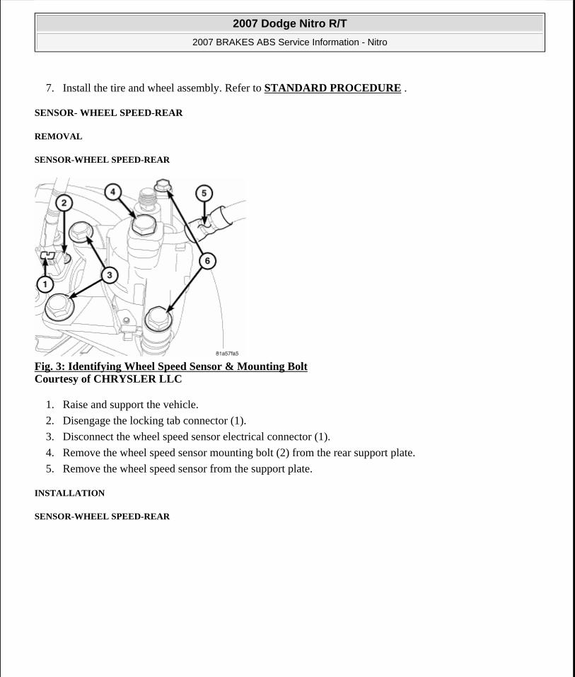
Fig. 3: Identifying Wheel Speed Sensor & Mounting Bolt Courtesy of CHRYSLER LLC
1. Raise and support the vehicle.
2. Disengage the locking tab connector (1).
3. Disconnect the wheel speed sensor electrical connector (1).
4. Remove the wheel speed sensor mounting bolt (2) from the rear support plate.
5. Remove the wheel speed sensor from the support plate.
INSTALLATION
SENSOR-WHEEL SPEED-REAR
2007 Dodge Nitro R/T
2007 BRAKES ABS Service Information - Nitro
Microsoft
Saturday, August 22, 2009 11:51:40 AM Page 11 © 2005 Mitchell Repair Information Company, LLC.
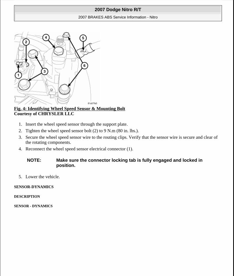
Fig. 4: Identifying Wheel Speed Sensor & Mounting Bolt Courtesy of CHRYSLER LLC
1. Insert the wheel speed sensor through the support plate.
2. Tighten the wheel speed sensor bolt (2) to 9 N.m (80 in. lbs.).
3. Secure the wheel speed sensor wire to the routing clips. Verify that the sensor wire is secure and clear of the rotating components.
4. Reconnect the wheel speed sensor electrical connector (1).
5. Lower the vehicle.
SENSOR-DYNAMICS
DESCRIPTION
SENSOR - DYNAMICS
NOTE: Make sure the connector locking tab is fully engaged and locked in position.
2007 Dodge Nitro R/T
2007 BRAKES ABS Service Information - Nitro
Microsoft
Saturday, August 22, 2009 11:51:40 AM Page 12 © 2005 Mitchell Repair Information Company, LLC.

Fig. 5: Identifying Nuts, Dynamics Sensor & Electrical Connector Courtesy of CHRYSLER LLC
The Yaw Rate and Lateral Acceleration Sensors are housed into one unit known as the Dynamics Sensor (2). The sensor is used to measure side-to-side (Lateral) motion and vehicle rotational sensing (how fast the vehicle is turning - Yaw).
Yaw and Lateral Acceleration Sensors cannot be serviced separately. The entire Dynamics Sensor (2) must be replaced when necessary.
REMOVAL
SENSOR-DYNAMICS
Fig. 6: Identifying Nuts, Dynamics Sensor & Electrical Connector Courtesy of CHRYSLER LLC
1. Remove the center console. Refer to REMOVAL .
2007 Dodge Nitro R/T
2007 BRAKES ABS Service Information - Nitro
Microsoft
Saturday, August 22, 2009 11:51:40 AM Page 13 © 2005 Mitchell Repair Information Company, LLC.

2. Disconnect electrical connector (3) from the dynamics sensor (2).
3. Remove the two nuts (1) securing the sensor to the floor.
4. Remove the sensor (2).
INSTALLATION
SENSOR-DYNAMICS
Fig. 7: Identifying Nuts, Dynamics Sensor & Electrical Connector Courtesy of CHRYSLER LLC
1. Install the dynamics sensor (2) to the vehicle.
2. Install the electrical connector (3) making sure that the connector is fully seated into the sensor (2)
3. Install the two retaining nuts (1) and tighten to 9 N.m (80 in. lbs.).
4. Install the floor console. Refer to INSTALLATION .
SENSOR-STEERING ANGLE
DESCRIPTION
SENSOR-STEERING ANGLE
Under transient cornering conditions the lateral acceleration sensor does not measure the true sway force on the car. In order to compensate for this the system uses the driver's steering command (Steering angle sensor) and vehicle speed to estimate the true sway force. This signal is matched with the lateral acceleration sensor signal to ensure a significantly-reduced transient sway of the vehicle body.
REMOVAL
NOTE: Steering angle sensor is part of the airbag clockspring and is not serviced separately from the clockspring.
2007 Dodge Nitro R/T
2007 BRAKES ABS Service Information - Nitro
Microsoft
Saturday, August 22, 2009 11:51:40 AM Page 14 © 2005 Mitchell Repair Information Company, LLC.

SENSOR-STEERING ANGLE
1. For removal of the steering angle sensor. Refer to REMOVAL .
INSTALLATION
SENSOR-STEERING ANGLE
1. For installation of the steering angle sensor. Refer to INSTALLATION .
ESP SWITCH
DESCRIPTION
SWITCH - ESP
Fig. 8: Identifying Instrument Panel Switches Courtesy of CHRYSLER LLC
The ESP switch (5) is located in the center stack (1) of the instrument panel. If the switch is damaged or inoperative the complete accessory switch bank assembly must be replaced.
REMOVAL
SWITCH - ESP
NOTE: Steering angle sensor is part of the airbag clockspring and is not serviced separately from the clockspring.
NOTE: Steering angle sensor is part of the airbag clockspring and is not serviced separately from the clockspring.
WARNING: On vehicles equipped with airbags, disable the airbag system before
2007 Dodge Nitro R/T
2007 BRAKES ABS Service Information - Nitro
Microsoft
Saturday, August 22, 2009 11:51:40 AM Page 15 © 2005 Mitchell Repair Information Company, LLC.
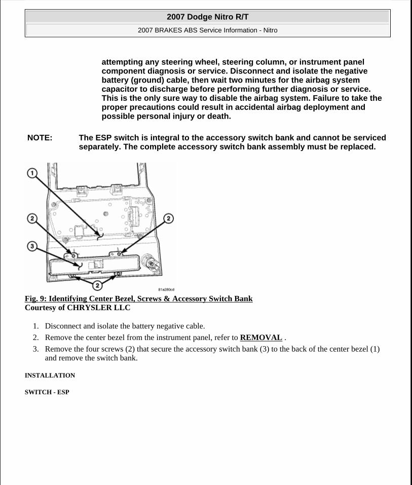
Fig. 9: Identifying Center Bezel, Screws & Accessory Switch Bank Courtesy of CHRYSLER LLC
1. Disconnect and isolate the battery negative cable.
2. Remove the center bezel from the instrument panel, refer to REMOVAL .
3. Remove the four screws (2) that secure the accessory switch bank (3) to the back of the center bezel (1) and remove the switch bank.
INSTALLATION
SWITCH - ESP
attempting any steering wheel, steering column, or instrument panel component diagnosis or service. Disconnect and isolate the negative battery (ground) cable, then wait two minutes for the airbag system capacitor to discharge before performing further diagnosis or service. This is the only sure way to disable the airbag system. Failure to take the proper precautions could result in accidental airbag deployment and possible personal injury or death.
NOTE: The ESP switch is integral to the accessory switch bank and cannot be serviced separately. The complete accessory switch bank assembly must be replaced.
2007 Dodge Nitro R/T
2007 BRAKES ABS Service Information - Nitro
Microsoft
Saturday, August 22, 2009 11:51:40 AM Page 16 © 2005 Mitchell Repair Information Company, LLC.

Fig. 10: Identifying Center Bezel, Screws & Accessory Switch Bank Courtesy of CHRYSLER LLC
1. Position the accessory switch bank (3) onto the back of the instrument panel center bezel (1).
2. Install the four screws (2) that secure the accessory switch bank to the center bezel. Tighten the screws to 2 N.m (17 in. lbs.).
3. Install the center bezel onto the instrument panel, refer to INSTALLATION .
4. Connect the battery negative cable.
5. Verify ESP system operation.
HYDRAULIC/MECHANICAL
HCU (HYDRAULIC CONTROL UNIT)
DESCRIPTION
HYDRAULIC CONTROL UNIT
The HCU consists of a valve body, pump motor, and wire harness.
OPERATION
HYDRAULIC CONTROL UNIT
Accumulators in the valve body store extra fluid released to the system for ABS mode operation. The pump provides the fluid volume needed and is operated by a DC type motor. The motor is controlled by the ABM.
The valves modulate brake pressure during antilock braking and are controlled by the ABM.
NOTE: There are different accessory switch banks available based on the option content of the vehicle. Ensure the switch pod being installed matches the vehicle options.
2007 Dodge Nitro R/T
2007 BRAKES ABS Service Information - Nitro
Microsoft
Saturday, August 22, 2009 11:51:40 AM Page 17 © 2005 Mitchell Repair Information Company, LLC.

The HCU provides four channel pressure control to the front and rear brakes. Two channels control the rear wheel brakes individually. The two remaining channels control the front wheel brakes individually.
During antilock braking, the solenoid valves are opened and closed as needed. The valves are not static. They are cycled rapidly and continuously to modulate pressure and control wheel slip and deceleration.
During normal braking, the HCU solenoid valves and pump are not activated. The master cylinder and power booster operate the same as a vehicle without an ABS brake system.
During antilock braking, solenoid valve pressure modulation occurs in three stages, pressure increase, pressure hold, and pressure decrease. The valves are all contained in the valve body portion of the HCU.
PRESSURE DECREASE
The outlet valve is opened and the inlet valve is closed during the pressure decrease cycle.
A pressure decrease cycle is initiated when speed sensor signals indicate high wheel slip at one or more wheels. At this point, the ABM closes the inlet then opens the outlet valve, which also opens the return circuit to the accumulators. Fluid pressure is allowed to bleed off (decrease) as needed to prevent wheel lock.
Once the period of high wheel slip has ended, the ABM closes the outlet valve and begins a pressure increase or hold cycle as needed.
PRESSURE HOLD
Both solenoid valves are closed in the pressure hold cycle. Fluid apply pressure in the control channel is maintained at a constant rate. The ABM maintains the hold cycle until sensor inputs indicate a pressure change is necessary.
PRESSURE INCREASE
The inlet valve is open and the outlet valve is closed during the pressure increase cycle. The pressure increase cycle is used to counteract unequal wheel speeds. This cycle controls re-application of fluid apply pressure due to changing road surfaces or wheel speed.
REMOVAL
HYDRAULIC CONTROL UNIT
1. Install prop rod on the brake pedal to keep pressure on the brake system.
2. Remove negative battery cable from the battery.
3. Pull up on the ABM harness connector release and remove connector.
2007 Dodge Nitro R/T
2007 BRAKES ABS Service Information - Nitro
Microsoft
Saturday, August 22, 2009 11:51:40 AM Page 18 © 2005 Mitchell Repair Information Company, LLC.

Fig. 11: Identifying Brake Lines & ABM Courtesy of CHRYSLER LLC
4. Remove brake lines (1) from the ABM (2).
Fig. 12: Identifying Bracket & ABM Unit Courtesy of CHRYSLER LLC
5. Remove the ABM unit (2) by pulling the unit from the bracket (1).
DISASSEMBLY
HYDRAULIC CONTROL UNIT
2007 Dodge Nitro R/T
2007 BRAKES ABS Service Information - Nitro
Microsoft
Saturday, August 22, 2009 11:51:40 AM Page 19 © 2005 Mitchell Repair Information Company, LLC.

Fig. 13: ABM & Mounting Screws Courtesy of CHRYSLER LLC
1. Remove the four screws (1) attaching the ABM module to the HCU (2). See Fig. 13.
1 - MOUNTING SCREWS2 - ABM
2007 Dodge Nitro R/T
2007 BRAKES ABS Service Information - Nitro
Microsoft
Saturday, August 22, 2009 11:51:40 AM Page 20 © 2005 Mitchell Repair Information Company, LLC.

Fig. 14: Identifying ABM, HCU & Solenoid Valve Stem Courtesy of CHRYSLER LLC
2. Separate the ABM module (1) from the HCU (2). See Fig. 14.
ASSEMBLY
HYDRAULIC CONTROL UNIT
1 - ABM2 - HCU3 - SOLENOID VALVE STEM
2007 Dodge Nitro R/T
2007 BRAKES ABS Service Information - Nitro
Microsoft
Saturday, August 22, 2009 11:51:40 AM Page 21 © 2005 Mitchell Repair Information Company, LLC.

Fig. 15: Solenoid Valve & Seal Courtesy of CHRYSLER LLC
1. Clean any debris off the mating surfaces of the HCU and ABM module.
2. If the seals on the components are not new, they must be replaced. Each of the solenoid valve stem seals (1) must be replaced. See Fig. 15 do not reuse solenoid valve stem seals .
1 - SEAL2 - SOLENOID VALVE STEM
CAUTION: When installing new O-rings or solenoid valve stem seals, do not use any type of lubricant.
2007 Dodge Nitro R/T
2007 BRAKES ABS Service Information - Nitro
Microsoft
Saturday, August 22, 2009 11:51:40 AM Page 22 © 2005 Mitchell Repair Information Company, LLC.

Fig. 16: O-Ring & O-Ring Mounting Groove Courtesy of CHRYSLER LLC
3. The pump/motor connector O-ring (1) should also be replaced if not new. See Fig. 16
1 - O-RING2 - O-RING MOUNTING GROOVE
2007 Dodge Nitro R/T
2007 BRAKES ABS Service Information - Nitro
Microsoft
Saturday, August 22, 2009 11:51:40 AM Page 23 © 2005 Mitchell Repair Information Company, LLC.

Fig. 17: Identifying ABM, HCU & Solenoid Valve Stem Courtesy of CHRYSLER LLC
4. Align components and install the ABM module on the HCU. See Fig. 17.
1 - ABM2 - HCU3 - SOLENOID VALVE STEM
2007 Dodge Nitro R/T
2007 BRAKES ABS Service Information - Nitro
Microsoft
Saturday, August 22, 2009 11:51:40 AM Page 24 © 2005 Mitchell Repair Information Company, LLC.

Fig. 18: ABM & Mounting Screws Courtesy of CHRYSLER LLC
5. Install the four screws attaching the ABM module to the HCU. See Fig. 18. Tighten the mounting screws to 2 N.m (17 in. lbs.) torque.
6. If the mounting bracket needs to be installed, install the mounting pins in the HCU as necessary and tighten to 14 N.m (125 in. lbs.) torque. Insert the mounting pins into the grommets mounted in the bracket, then install the single mounting bolt. Tighten the mounting bolt to 14 N.m (125 in. lbs.) torque.
7. Install the HCU in the vehicle. See INSTALLATION.
INSTALLATION
HYDRAULIC CONTROL UNIT
1 - MOUNTING SCREWS2 - ABM
2007 Dodge Nitro R/T
2007 BRAKES ABS Service Information - Nitro
Microsoft
Saturday, August 22, 2009 11:51:40 AM Page 25 © 2005 Mitchell Repair Information Company, LLC.

Fig. 19: Identifying Bracket & ABM Unit Courtesy of CHRYSLER LLC
1. Install ABM (2) on the mounting bracket rubber pockets (1).
Fig. 20: Identifying Brake Lines & ABM Courtesy of CHRYSLER LLC
2. Install brake lines to the ABM (2) and tighten to 20 N.m (180 in. lbs.).
3. Install wiring harness connector to the ABM and push down on the release to secure the connector.
4. Install negative battery cable to the battery.
5. Bleed ABS brake system. See STANDARD PROCEDURE.
NOTE: If the ABM module is being replaced with a new ABM module it must be reprogrammed with the use of a scan tool.
2007 Dodge Nitro R/T
2007 BRAKES ABS Service Information - Nitro
Microsoft
Saturday, August 22, 2009 11:51:40 AM Page 26 © 2005 Mitchell Repair Information Company, LLC.