absolute three-dimensional shape measurement using coded ... · absolute three-dimensional shape...
TRANSCRIPT
Absolute three-dimensional shapemeasurement using coded fringe
patterns without phase unwrapping orprojector calibration
William Lohry, Vincent Chen and Song Zhang∗Department of Mechanical Engineering, Iowa State University, Ames, IA 50011
Abstract: This paper presents a novel stereo-phase-based absolutethree-dimensional (3D) shape measurement that requires neither phaseunwrapping nor projector calibration. This proposed method can be dividedinto two steps: (1) obtain a coarse disparity map from the quality map;and (2) refine the disparity map using wrapped phase. Fringe patternsare modified to encode the quality map for efficient and accurate stereomatching. Experiments demonstrated that the proposed method couldachieve high-quality 3D measurement even with extremely low-qualityfringe patterns.
© 2014 Optical Society of America
OCIS codes: (120.0120) Instrumentation, measurement and metrology; (110.6880) Three-dimensional image acquisition; (320.7100) Ultrafast measurements; (120.5050) Phasemeasurement.
References and links1. D. Scharstein and R. Szeliski, “A taxonomy and evaluation of dense two-frame stereo correspondence algo-
rithms,” Intl J. Comp. Vis. 47(1-3), 7–42 (2002).2. U. R. Dhond and J. K. Aggarwal, “Structure from stereo-a review,” IEEE Trans. Systems, Man. and Cybernetics
19(6), 1489–1510 (1989).3. R. I. Hartley and A. Zisserman, Multiple View Geometry in Computer Vision (Cambridge University Press, 2000).4. T. Kanade and M. Okutomi, “A stereo matching algorithm with an adaptive window: Theory and experiment,”
IEEE Trans. Patt. Analy. and Mach. Intellig. 16(9), 920–932 (1994).5. V. Kolmogorov and R. Zabih, “Multi-camera scene reconstruction via graph cuts,” in Euro Conf. Comp. Vis., pp.
82–96 (2002).6. J. Kostkova and R. Sara, “Stratified dense matching for stereopsis in complex scenes,” in Proc. Brit. Mach. Vis.
Conf., pp. 339–348 (2003).7. H. Hirschmuller, “Stereo processing by semiglobal matching and mutual information,” IEEE Trans. Patt. Analy-
sis Mach. Intellig. 30(2), 328–341 (2008).8. F. Besse, C. Rother, A. W. Fitzgibbon, and J. Kautz, “PMBP: PatchMatch belief propagation for correspondence
field estimation,” Intl J. Comp. Vis. pp. 1–12 (2013).9. A. Geiger, M. Roser, and R. Urtasun, “Efficient large-scale stereo matching,” 6492, 25–38 (2011).
10. J. Salvi, S. Fernandez, T. Pribanic, and X. Llado, “A state of the art in structured light patterns for surfaceprofilometry,” Patt. Recogn. 43(8), 2666–2680 (2010).
11. Z. Zhang, “Microsoft kinect sensor and its effect,” IEEE Multimedia 19(2), 4–10 (2012).12. O. Hall-Holt and S. Rusinkiewicz, “Stripe boundary codes for real-time structured-light range scanning of mov-
ing objects,” in The 8th IEEE International Conference on Computer Vision, pp. II: 359–366 (2001).13. S. Rusinkiewicz, O. Hall-Holt, and M. Levoy, “Real-time 3D model acquisition,” ACM Trans. Graph. 21(3),
438–446 (2002).
#199468 - $15.00 USD Received 14 Oct 2013; revised 24 Dec 2013; accepted 3 Jan 2014; published 13 Jan 2014(C) 2014 OSA 27 January 2014 | Vol. 22, No. 2 | DOI:10.1364/OE.22.001287 | OPTICS EXPRESS 1287
14. D. Malacara, ed., Optical Shop Testing, 3rd ed. (John Wiley and Sons, NY, 2007).15. S. Zhang, “Recent progresses on real-time 3-D shape measurement using digital fringe projection techniques,”
Opt. Laser Eng. 48(2), 149–158 (2010).16. G. Geng, “Structured-light 3D surface imaging: a tutorial,” Advances in Opt. and Photonics 3(2), 128–160 (2011).17. S. Gorthi and P. Rastogi, “Fringe projection techniques: Whither we are?” Opt. Laser. Eng. 48, 133–140 (2010).18. D. C. Ghiglia and M. D. Pritt, eds., Two-Dimensional Phase Unwrapping: Theory, Algorithms, and Software
(John Wiley and Sons, 1998).19. K. Creath, “Step height measurement using two-wavelength phase-shifting interferometry,” Appl. Opt. 26(14),
2810–2816 (1987).20. Y.-Y. Cheng and J. C. Wyant, “Multiple-Wavelength Phase Shifting Interferometry,” Appl. Opt. 24, 804–807
(1985).21. G. Sansoni, M. Carocci, and R. Rodella, “Three-dimensional vision based on a combination of gray-code and
phase-shift light projection: analysis and compensation of the systematic errors,” Appl. Opt. 38, 6565–6573(1999).
22. U. R. Dhond and J. K. Aggarwal, “Real-time scalable depth sensing with hybrid structured light illumination,”IEEE Trans. Imag. Proc. 23(1), 97–109 (2013).
23. S. Zhang, “Composite phase-shifting algorithm for absolute phase measurement,” Opt. Laser Eng. 50(11), 1538–1541 (2012).
24. X. Chen, J. Xi, Y. Jin, and J. Sun, “Accurate calibration for a camera–projector measurement system based onstructured light projection,” Opt. Laser Eng. 47(3), 310–319 (2009).
25. Q. Hu, P. S. Huang, Q. Fu, and F. P. Chiang, “Calibration of a 3-D Shape Measurement System,” Opt. Eng. 42(2),487–493 (2003).
26. F. J. Cuevas, M. Servin, and R. Rodriguez-Vera, “Depth object recovery using radial basis functions,” Opt. Com-mun. 163(4), 270–277 (1999).
27. R. Legarda-Saenz, T. Bothe, and W. P. Juptner, “Accurate procedure for the calibration of a structured lightsystem,” Opt. Eng. 43(2), 464?–471 (2004).
28. S. Zhang and P. S. Huang, “Novel method for structured light system calibration,” Opt. Eng. 45(8), 083,601(2006).
29. W. Gao, L. Wang, and Z. Hu, “Flexible method for structured light system calibration,” Opt. Eng. 47(8), 083,602(2008).
30. R. Yang, S. Cheng, and Y. Chen, “Flexible and accurate implementation of a binocular structured light system,”Opt. Lasers Eng. 46(5), 373–379 (2008).
31. Z. Li, Y. Shi, C. Wang, and Y. Wang, “Accurate calibration method for a structured light system,” Opt. Eng.47(5), 053,604 (2008).
32. S. Kakunai, T. Sakamoto, and K. Iwata, “Profile measurement taken with liquid-crystal grating,” Appl. Opt.38(13), 2824–2828 (1999).
33. H. Guo, H. He, and M. Chen, “Gamma correction for digital fringe projection profilometry,” Appl. Opt. 43,2906–2914 (2004).
34. B. Pan, Q. Kemao, L. Huang, and A. Asundi, “Phase error analysis and compensation for nonsinusoidal wave-forms in phase-shifting digital fringe projection profilometry,” Opt. Lett. 34(4), 2906–2914 (2009).
35. P. S. Huang, C. Zhang, and F.-P. Chiang, “High-speed 3-D Shape Measurement Based on Digital Fringe Projec-tion,” Opt. Eng. 42(1), 163–168 (2002).
36. S. Zhang and P. S. Huang, “Phase error compensation for a three-dimensional shape measurement system basedon the phase shifting method,” Opt. Eng. 46(6), 063,601 (2007).
37. S. Zhang and S.-T. Yau, “Generic nonsinusoidal phase error correction for three-dimensional shape measurementusing a digital video projector,” Appl. Opt. 46(1), 36–43 (2007).
38. J. Pan, P. S. Huang, and F.-P. Chiang, “Color phase-shifting technique for three-dimensional shape measurement,”Opt. Eng. 45(12), 013,602 (2006).
39. J. Pan, P. S. Huang, and F.-P. Chiang, “Color-coded binary fringe projection technique for 3-D shape measure-ment,” Opt. Eng. 44(12), 023,606 (2005).
40. C. Je, S. W. Lee, and R.-H. Park, “Colour-stripe permutation pattern for rapid structured-light range imaging,”Opt. Comm. 285(9), 2320–2331 (2012).
41. C. Je, S. W. Lee, and R.-H. Park, “Experimental comparison of phase-shifting fringe projection and statisticalpattern projection for active triangulation systems,” in Proc. 6th Asian Conference on Computer Vision, pp. 270–275 (2004).
42. Z. Zhang, C. E. Towers, and D. P. Towers, “Time efficient color fringe projection system for 3D shape and colorusing optimum 3-frequency selection,” Opt. Express 14(14), 6444–6455 (2006).
43. K. G. Harding, “Color Encoded Morie Contouring,” in Proc. SPIE, vol. 1005, pp. 169–178 (1988).44. Z. J. Geng, “Rainbow 3-D camera: New concept of high-speed three vision system,” Opt. Eng. 35, 376–383
(1996).45. P. S. Huang, Q. Hu, F. Jin, and F. P. Chiang, “Color-encoded digital fringe projection technique for high-speed
three-dimensional surface contouring,” Opt. Eng. 38, 1065–1071 (1999).
#199468 - $15.00 USD Received 14 Oct 2013; revised 24 Dec 2013; accepted 3 Jan 2014; published 13 Jan 2014(C) 2014 OSA 27 January 2014 | Vol. 22, No. 2 | DOI:10.1364/OE.22.001287 | OPTICS EXPRESS 1288
46. S. Zhang and P. S. Huang, “High-resolution real-time three-dimensional shape measurement,” Opt. Eng. 45(12),123,601 (2006).
47. Y. Huang, Y. Shang, Y. Liu, and H. Bao, Handbook of 3D Machine Vision: Optical Metrology and Imaging, chap.3D shapes from Speckle, pp. 33–56, 1st ed. (CRC, 2013).
48. L. Zhang, N. Snavely, B. Curless, and S. M. Seitz, “Spacetime faces: High-resolution capture for modeling andanimation,” ACM Trans. Graph. 23(3), 548 – 558 (2004).
49. A. Wiegmann, H. Wagner, and R. Kowarschik, “Human face measurement by projecting bandlimited randompatterns,” Opt. Express 14(17), 7692–7698 (2006).
50. J. Davis, R. Ramamoorthi, and S. Rusinkiewicz, “Spacetime stereo: A unifying framework for depth from trian-gulation,” IEEE Trans. Patt. Anal. and Mach.e Intell. 27(2), 1–7 (2005).
51. L. Zhang, B. Curless, and S. Seitz, “Spacetime stereo: Shape recovery for dynamic scenes,” in Proc. Comp. Vis.Patt. Recogn., pp. 367–374 (2003).
52. W. Jang, C. Je, Y. Seo, and S. W. Lee, “Structured-light stereo: Comparative analysis and integration ofstructured-light and active stereo for measuring dynamic shape,” Opt. Laser Eng. 51(11), 1255–1264 (2013).
53. X. Han and P. Huang, “Combined stereovision and phase shifting method: use of a visibility-modulated fringepattern,” in SPIE Europe Optical Metrology, pp. 73,893H–73,893H (2009).
54. M. Schaffer, M. Große, B. Harendt, and R. Kowarschik, “Coherent two-beam interference fringe projection forhighspeed three-dimensional shape measurements,” Appl. Opt. 52(11), 2306–2311 (2013).
55. K. Liu and Y. Wang, “Phase channel multiplexing pattern strategy for active stereo vision,” in Intl Conf. 3DImaging (IC3D), pp. 1–8 (2012).
56. J. Salvi, J. Pages, and J. Batlle, “Pattern codification strategies in structured light systems,” Patt. Recogn. 37(4),827–849 (2004).
57. P. Lutzke, M. Schaffer, P. Kuhmstedt, R. Kowarschik, and G. Notni, “Experimental comparison of phase-shiftingfringe projection and statistical pattern projection for active triangulation systems,” in SPIE Optical Metrology2013, pp. 878,813–878,813 (2013).
58. C. Brauer-Burchardt, M. Moller, C. Munkelt, M. Heinze, P. Kuhmstedt, and G. Notni, “On the accuracy of pointcorrespondence methods in three-dimensional measurement systems using fringe projection,” Opt. Eng. 52(6),063,601–063,601 (2013).
59. Z. Li, K. Zhong, Y. Li, X. Zhou, and Y. Shi, “Multiview phase shifting: a full-resolution and high-speed 3Dmeasurement framework for arbitrary shape dynamic objects,” Opt. Lett. 38(9), 1389–1391 (2013).
60. K. Zhong, Z. Li, Y. Shi, C. Wang, and Y. Lei, “Fast phase measurement profilometry for arbitrary shape objectswithout phase unwrapping,” Opt. Laser Eng. 51(11), 1213–1222 (2013).
61. C. Brauer-Burchardt, P. Kuhmstedt, and G. Notni, “Phase unwrapping using geometric constraints for high-speedfringe projection based 3D measurements,” in SPIE Optical Metrology 2013, pp. 878,906–878,906 (2013).
62. M. Maruyama and S. Abe, “Range sensing by projecting multiple slits with random cuts,” IEEE Trans. Patt.Analysis Mach. Intellig. 15(6), 647–651 (1993).
63. K. Konolige, “Projected texture stereo,” in IEEE Intl Conf. Rob. Auto., pp. 148–155 (2010).64. Y. Wang and S. Zhang, “Superfast multifrequency phase-shifting technique with optimal pulse width modula-
tion,” Opt. Express 19(6), 5143–5148 (2011).65. S. Zhang and S.-T. Yau, “Three-dimensional shape measurement using a structured light system with dual cam-
eras,” Opt. Eng. 47(1), 013,604 (2008).
1. Introduction
Triangulation-based three-dimensional (3D) shape measurement can be classified into two cat-egories: the passive method (e.g. stereo vision) and the active method (e.g., structured light).In a passive stereo system, two images captured from different perspectives are used to detectcorresponding points in a scene to obtain 3D geometry [1, 2]. Detecting corresponding pointsbetween two stereo images is a well-studied problem in stereo vision. Since a correspondingpoint pair must lie on an epipolar line, the captured images are often rectified so that the epipo-lar lines run across each row [3]. This allows a method of finding corresponding points usinga “sliding window” approach, which defines the similarity of a match using cost, correlation,or probability. The difference between the horizontal position of the point in the left image andthat in the right image is called the disparity. This disparity can be directly converted into 3Dgeometry.
Standard cost-based matching approaches rely on the texture difference between a sourcepoint in one image with a target point in the other [4]. The cost represents the difference inintensity between the two windows on the epipolar line and is used to weigh various matches.
#199468 - $15.00 USD Received 14 Oct 2013; revised 24 Dec 2013; accepted 3 Jan 2014; published 13 Jan 2014(C) 2014 OSA 27 January 2014 | Vol. 22, No. 2 | DOI:10.1364/OE.22.001287 | OPTICS EXPRESS 1289
In a winner-takes-all approach, the disparity will be determined from the point in the rightimage that has the least cost with that of the source point in the left.
In addition to local methods, a number of global and semi-global methods have been sug-gested [5–8]. One method that worked especially well was the probabilistic model named Ef-ficient LArge-scale Stereo (ELAS) [9]. In this method, a number of support points from bothimages are chosen based on their response to a 3 × 3 Sobel filter. Groups of points are com-pared between images, and a Bayesian model determines their likelihood of matching. Since theELAS method is piecewise continuous, it works particularly well for objects with little texturevariation.
Passive stereo methods, despite recent advances, still suffer from the fundamental limitationof the method: finding corresponding pairs between two natural images. This requirement hin-ders the ability of this method to accurately and densely reconstruct many real-world objectssuch as uniform white surfaces. An alternative to a dual-camera stereo method is to replace onecamera with a projector and actively project a desired texture on the object surface for stereomatching [10]. This method is typically referred to as structured light. The structured systemsuses computer generated patterns that carries codewords through certain codification strategies.The coded patterns can be the pseudo-random dots (or speckle patterns, such as the MicrosoftKinect [11] uses), the binary structured patterns. If the codewords are unique, the correspon-dence between the projector and the camera is uniquely determined, and 3D information canbe calculated through triangulation once the system is calibrated. One of the major benefitsof using the pseudo-random codification approach is that it is easy to understand and easy toimplement for 3D shape measurement. The major disadvantage to this technique, however, isthat it is difficult for such techniques to achieve high-spatial resolution as it is limited by theprojector’s resolution in both the u and v directions.
The structured light systems often use binary patterns for 3D shape measurement with someachieving real-time capability [12, 13]. Because these techniques only uses 0s and 1s for codi-fication, they have the following advantages: (1) the coding and decoding algorithms are verysimple; (2) processing can be performed quickly since the algorithm is simple; and (3) it isvery robust to the noise since only two levels are used. Comparing with the codification withthe pseudo-random dots, it could achieve higher spatial resolution. This is because such a tech-nique uses vertical or horizontal stripes for codification, its spatial resolution is only limited bythe projector’s resolution in either u or v direction, but not both. However, the stripe width mustbe larger than one projector’s pixel, and to achieve projector pixel spatial resolution, a lot binarypatterns (typically a lot more than three patterns are required).Therefore, it is very difficult forthese methods to reach pixel level spatial resolution at very high speeds.
The binary coded patterns are continuous in one direction (along the stripe) but discrete in theother, limiting its achievable spatial resolution. Higher spatial resolution could be achieved byusing continuous patterns in both directions, and the patterns are typically sinusoidal in nature.The method of using sinusoidal structured patterns for codification is also called digital fringeprojection or DFP. Sinusoidal patterns are often analyzed using phase-shifting algorithms. Inoptical metrology, the phase-shifting-based structured-light method is extensively used due toits accuracy and speed [14]. For a DFP system, instead of finding corresponding point usingintensity of the structured patterns, it uses phase as a constraint to solve for (x,y,z) coordinatespixel by pixel if the system is calibrated [15]. Because of their overwhelmingly advantageousfeatures over the other types of structured light techniques, the DFP techniques have been exten-sively adopted in numerous disciplines [16,17]. The major advantages are: (1) High spatial res-olution. The phase-shifting technique permits pixel-by-pixel 3D shape measurement, making itpossible to achieve camera pixel-level spatial resolution; (2) Resistance to ambient light influ-ences. Instead of directly utilizing intensity, the phase-shifting method analyzes phase informa-
#199468 - $15.00 USD Received 14 Oct 2013; revised 24 Dec 2013; accepted 3 Jan 2014; published 13 Jan 2014(C) 2014 OSA 27 January 2014 | Vol. 22, No. 2 | DOI:10.1364/OE.22.001287 | OPTICS EXPRESS 1290
tion of the structured pattern. The ambient light influence is automatically canceled out, albeitthe signal-to-noise ratio (SNR) might be sacrificed if the ambient light is too strong compar-ing with the projection light; (3) Lower sensitivity to surface reflectivity variations. Typically,the phase-shifting method computes the phase using the arctangent function point-by-point,and the influence of surface reflectivity information is also canceled out because it is constantfor each pixel; (4) High-speed 3D shape measurement. Since the whole measurement area canbe captured and processed once, this technique, as well as other structured light techniques,can achieve high measurement speed; and (5) Can achieve high measurement accuracy. Un-like other structured light techniques, the phase-shifting based method allows precise sub-pixelcorrespondence between the projector and the camera without any interpolation. Therefore,theoretically, it could achieve highly accurate 3D shape measurement if calibration is properlyperformed.
In the meantime, comparing with other structured light methods, the DFP method suffersfrom several problems. Firstly, the phase obtained from the phase-shifting algorithm usuallyranges from 0 to 2π with 2π discontinuities. To recover 3D shape, the continuous phase mustbe obtained, usually requiring spatial or temporal phase unwrapping. The spatial phase unwrap-ping, by looking at neighboring pixel phase information, detects the 2π jumps and removesthem by adding or subtracting multiples of 2π [18]. Even though numerous spatial phase un-wrapping algorithms have been developed, a spatial phase unwrapping algorithm only worksfor “smooth” surfaces without abrupt changes (inducing more than π between two neighboringpixels) from one point to the other. Therefore, the spatial phase unwrapping cannot be usedfor large step-height or isolated object measurement. Furthermore, the phase obtained by spa-tial phase unwrapping only provides relative phase that only gives the relative shape of theobject to a reference point; and to recover the absolute geometry, absolute phase is required.The absolute phase can be obtained by temporal phase unwrapping. Instead of comparing thephase values of neighboring pixels, a temporal phase unwrapping algorithm uses clues fromother phase values in the same camera pixel. Over the past many years, many temporal phaseunwrapping methods have been developed including two- [19] or multi-frequency [20] phase-shifting, the gray-coding plus phase-shifting [21], composite of random or stair image withphase-shifting [22, 23] methods. However, all these temporal phase unwrapping requires moreimages to be captured, slowing down the measurement speeds. For high-speed applications,such a method is usually not desirable.
Secondly, the projector has to be accurately calibrated [24]. Even though numerous digitalvideo projector calibration methods [25–27] have been developed, accurate projector calibra-tion remains difficult. This is mainly because, unlike a camera, a projector cannot directly cap-ture images like a camera. We pioneered the method of converting the structured light systemcalibration to the standard stereo system calibration by enabling the projector to “capture” im-ages like a camera [28]. Despite some recent advancements [29–31] on structured light calibra-tion, we still found great difficulty accurately calibrating structured light systems, especially forhigh-speed 3D shape measurement systems. Furthermore, all these developed good calibrationmethods have the following requirements: (1) the projector can be manipulated pixel by pixel;(2) the projector is at least nearly focused when perform any measurement; and (3) the absolutecorrespondence between camera pixel and the projector pixel (or at least line). However, for aphysical grating or slide projector, the first requirement cannot be satisfied; for a system withan out-of-focus projector, the second requirement cannot be satisfied; and for a high-speed 3Dshape measurement system, as aforementioned, satisfying requirement 3 usually slows downthe measurement. Therefore, calibrating generic structured light system remains challenging.
Lastly, since the traditional DFP-based method recovers 3D geometry directly from thephase, the phase quality is essential to measurement accuracy: any noise or distortion on the
#199468 - $15.00 USD Received 14 Oct 2013; revised 24 Dec 2013; accepted 3 Jan 2014; published 13 Jan 2014(C) 2014 OSA 27 January 2014 | Vol. 22, No. 2 | DOI:10.1364/OE.22.001287 | OPTICS EXPRESS 1291
phase will be reflected on the final 3D measurement. Unlike the structured light system usinga binary coding method, the DFP system requires calibrating the nonlinearity of the projec-tion and compensating for the errors associated with it. Even though nonlinearity correctionis relatively mature with many methods developed [32–37], our research found that the non-linearity of the projector actually changes over time, complicating the problem since a regularnonlinearity calibration is usually necessary [15].
For standard camera-projector based structured light systems, color-coded structured patternscan be used to speed up the measurement [38–45]. However, the object surface color could in-fluence, to a various degree, the measurement quality. This is because the color of the objectcould change the coded information carried on by the patterns. For example, if the object sur-face is blue, the information carried on by blue or red colors could be completely (at least par-tially) lost. Furthermore, the color coupling problem [38] further complicates the measurementsystem development. Therefore, the black-and-white coded patterns are typically preferrablefor high accuracy measurement, and to achieve high speed, these patterns are usually switchedquickly [46].
To mitigate some of problems associated with passive stereo or actively structured light meth-ods, the natural approach is to combine these two methods together: using two cameras and oneprojector. Over the years, different methods have been developed. In general, they use randomdots [11, 47], bandlimited random patterns [49], binary-coded patterns [48, 50], color struc-tured patterns [51, 52], or phase-shifted sinusoidal fringe patterns [53–55]. The overviews canbe found in the literature [56–58]. Typically, the random-pattern-based methods could achievehigh speed but the achievable spatial resolution is relatively low. The binary-coding method isrelatively robust to noise, yet spatial resolution is usually limited by the both the projector andthe camera, albeit is higher than that achieved by those random-dots based methods. The useof color could speed the measurement, yet induces the problems associated with color (e.g.,color coupling, susceptibility to object surface color) [38]. The phase-shifting based DFP sys-tem can achieve high spatial resolution (only limited by the camera); and could also achievehigh speeds since only three patterns are required for dense 3D shape measurement. Therefore,for both high spatial resolution and high speed 3D shape measurements, the DFP technique isusually adopted.
The phase-based method becomes more powerful if neither spatial nor temporal phase un-wrapping is necessary. Taking advantage of the geometric constraints of the trio sensors (twocameras and one projector), References [59–61] presented 3D shape measurement techniqueswithout phase unwrapping. However, similar to prior phase-based methods, these methods re-quire projector calibration, which is usually not easy and even more difficult for nonlinear pro-jection sources. Furthermore, the geometric constraint usually requires globally backward andforward checking for matching point location, limiting its speed and capability of measuringsharp changing surface geometries.
We propose a method to alleviate the problems associated with the aforementioned tech-niques. This proposed method combines the advantages of the stereo approach and the phase-based approach: using a stereo matching algorithm to obtain the coarse disparity map to avoidthe global searching problem associated with the method in [59]; and using the local wrappedphase information to further refine the coarse disparity for higher measurement accuracy. Fur-thermore, the proposed method does not require any geometric constraint imposed by the pro-jector, and thus no projector calibration is required, further simplifying the system development.
Section 2 explains the principle of the proposed method. Section 3 shows the experimen-tal results. Section 4 discusses the advantages and shortcomings of the proposed method, andSec. 5 summarizes this paper.
#199468 - $15.00 USD Received 14 Oct 2013; revised 24 Dec 2013; accepted 3 Jan 2014; published 13 Jan 2014(C) 2014 OSA 27 January 2014 | Vol. 22, No. 2 | DOI:10.1364/OE.22.001287 | OPTICS EXPRESS 1292
2. Principle
2.1. Three-step phase-shifting algorithm
For high-speed applications, a three phase-shifting algorithm is desirable. For a three-stepphase-shifting algorithm with equal phase shifts, three fringe patterns can be described as
I1(x,y) = I′+ I′′ cos(φ −2π/3) , (1)I2(x,y) = I′+ I′′ cos(φ) , (2)I3(x,y) = I′+ I′′ cos(φ +2π/3) , (3)
where I′(x,y) represents the average intensity, I′′(x,y) the intensity modulation, and φ(x,y) thephase to be solved for. Solving these three equations leads to
φ(x,y) = tan−1[√
3(I1−I3)2I2−I1−I3
], (4)
γ(x,y) = I′′I′ =
√3(I1−I3)2+(2I2−I1−I3)2
I1+I2+I3. (5)
Here γ(x,y) is the data modulation that represents the quality of each data point with 1 beingthe best, and its map is referred to as the quality map.
2.2. Combination of statistical random pattern with phase-shifting fringe pattern
The key to the success of the proposed method is using the stereo algorithm to provide a coarsedisparity map. However, none of these parameters, I′, I′′, or φ will provide information aboutmatch correspondence for a case like a uniform flat board. To solve this problem without in-creasing the number of fringe patterns used, we could encode one or more of these variablesto make them locally unique. Since the phase φ is most closely related to the 3D measurementquality and we often want to capture an unmodified texture, we propose to change I′′.
The encoded pattern was generated using band-limited 1/ f noise where 120 pixels < f < 1
5 pixelsand with intensity Ip(x,y) such that 0.5 < Ip(x,y) < 1. Here Ip(x,y) is randomly generated. InEqs. (1)-(3), I′′(x,y) was changed to Ip(x,y)I′′(x,y). The modified fringe images are describedas
I1(x,y) = I′+ Ip(x,y)I′′ cos(φ −2π/3) , (6)I2(x,y) = I′+ Ip(x,y)I′′ cos(φ) , (7)I3(x,y) = I′+ Ip(x,y)I′′ cos(φ +2π/3) . (8)
Figure 1 illustrates the encoded pattern Ip(x,y) and one of the modified fringe patterns. Sincethe encoded pattern is still centered around the same average intensity value, the captured tex-ture image or phase should not be affected in theory, albeit the phase signal to noise ratio maybe lower, and the nonlinearity of the projection system may affect texture image quality. Fur-thermore, any naturally occurring quality map changes caused by object texture or proximityto the projector will be visible from both of the cameras, canceling the effect.
The 2D varying pattern can improve the cost distinction between a correct match and theother possible disparities. While random pattern stereo matching algorithms have been pro-posed [62, 63], they have been used for the final disparity calculation rather than as an inter-mediary to matching phase. In this paper, the random pattern is used to match correspondingphase points between two images, without the need for global phase unwrapping. Once thecorresponding points have been determined, refinement of the disparity map can proceed usingonly the wrapped phase locally.
#199468 - $15.00 USD Received 14 Oct 2013; revised 24 Dec 2013; accepted 3 Jan 2014; published 13 Jan 2014(C) 2014 OSA 27 January 2014 | Vol. 22, No. 2 | DOI:10.1364/OE.22.001287 | OPTICS EXPRESS 1293
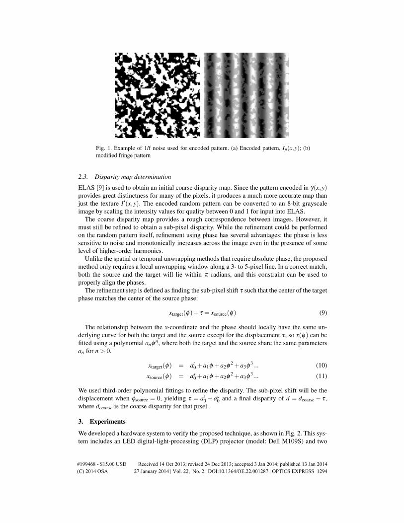
Fig. 1. Example of 1/f noise used for encoded pattern. (a) Encoded pattern, Ip(x,y); (b)modified fringe pattern
2.3. Disparity map determination
ELAS [9] is used to obtain an initial coarse disparity map. Since the pattern encoded in γ(x,y)provides great distinctness for many of the pixels, it produces a much more accurate map thanjust the texture I′(x,y). The encoded random pattern can be converted to an 8-bit grayscaleimage by scaling the intensity values for quality between 0 and 1 for input into ELAS.
The coarse disparity map provides a rough correspondence between images. However, itmust still be refined to obtain a sub-pixel disparity. While the refinement could be performedon the random pattern itself, refinement using phase has several advantages: the phase is lesssensitive to noise and monotonically increases across the image even in the presence of somelevel of higher-order harmonics.
Unlike the spatial or temporal unwrapping methods that require absolute phase, the proposedmethod only requires a local unwrapping window along a 3- to 5-pixel line. In a correct match,both the source and the target will lie within π radians, and this constraint can be used toproperly align the phases.
The refinement step is defined as finding the sub-pixel shift τ such that the center of the targetphase matches the center of the source phase:
xtarget(φ)+ τ = xsource(φ) (9)
The relationship between the x-coordinate and the phase should locally have the same un-derlying curve for both the target and the source except for the displacement τ , so x(φ) can befitted using a polynomial anφ n, where both the target and the source share the same parametersan for n > 0.
xtarget(φ) = at0 +a1φ +a2φ
2 +a3φ3... (10)
xsource(φ) = as0 +a1φ +a2φ
2 +a3φ3... (11)
We used third-order polynomial fittings to refine the disparity. The sub-pixel shift will be thedisplacement when φsource = 0, yielding τ = at
0− as0 and a final disparity of d = dcoarse− τ ,
where dcoarse is the coarse disparity for that pixel.
3. Experiments
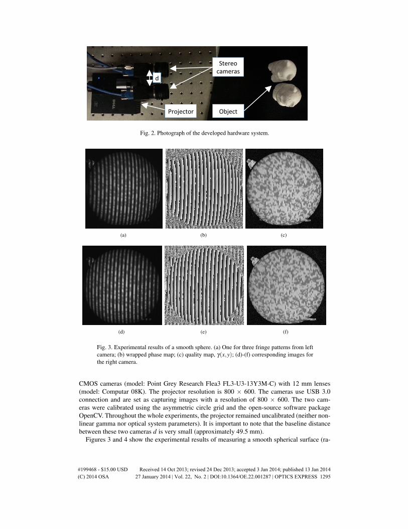
We developed a hardware system to verify the proposed technique, as shown in Fig. 2. This sys-tem includes an LED digital-light-processing (DLP) projector (model: Dell M109S) and two
#199468 - $15.00 USD Received 14 Oct 2013; revised 24 Dec 2013; accepted 3 Jan 2014; published 13 Jan 2014(C) 2014 OSA 27 January 2014 | Vol. 22, No. 2 | DOI:10.1364/OE.22.001287 | OPTICS EXPRESS 1294
Stereo&cameras&
Object&Projector&
d&
Fig. 2. Photograph of the developed hardware system.
(a) (b) (c)
(d) (e) (f)
Fig. 3. Experimental results of a smooth sphere. (a) One for three fringe patterns from leftcamera; (b) wrapped phase map; (c) quality map, γ(x,y); (d)-(f) corresponding images forthe right camera.
CMOS cameras (model: Point Grey Research Flea3 FL3-U3-13Y3M-C) with 12 mm lenses(model: Computar 08K). The projector resolution is 800 × 600. The cameras use USB 3.0connection and are set as capturing images with a resolution of 800 × 600. The two cam-eras were calibrated using the asymmetric circle grid and the open-source software packageOpenCV. Throughout the whole experiments, the projector remained uncalibrated (neither non-linear gamma nor optical system parameters). It is important to note that the baseline distancebetween these two cameras d is very small (approximately 49.5 mm).
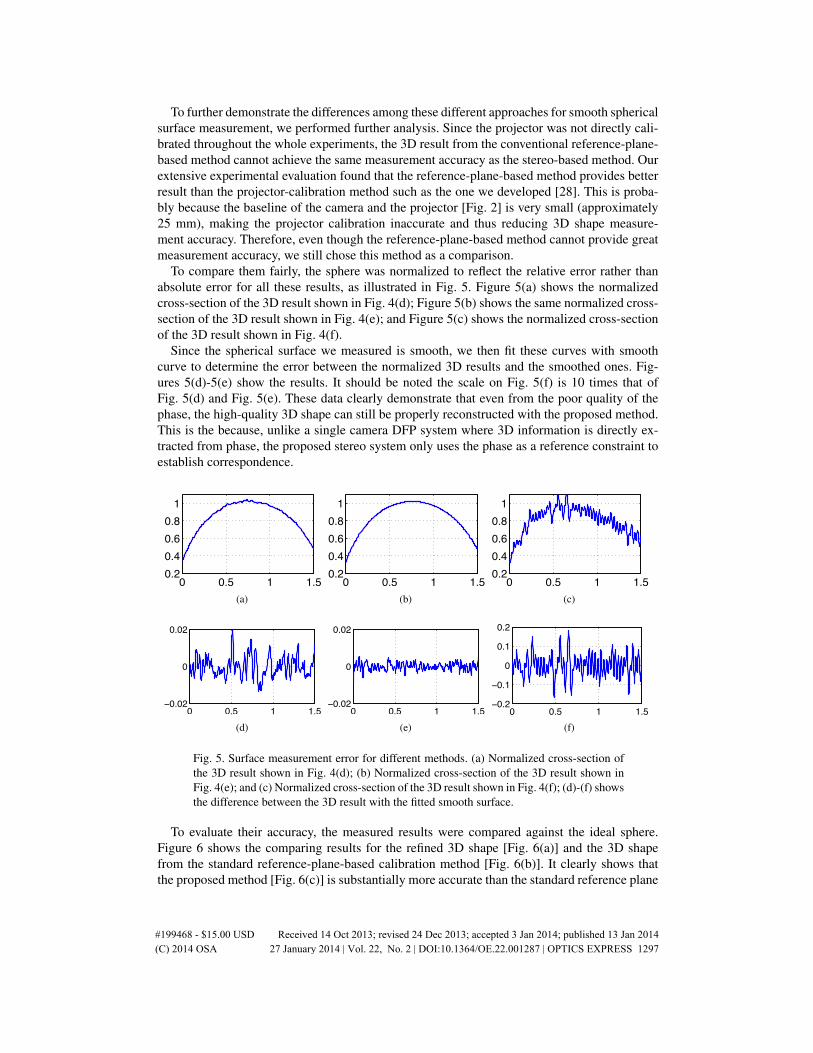
Figures 3 and 4 show the experimental results of measuring a smooth spherical surface (ra-
#199468 - $15.00 USD Received 14 Oct 2013; revised 24 Dec 2013; accepted 3 Jan 2014; published 13 Jan 2014(C) 2014 OSA 27 January 2014 | Vol. 22, No. 2 | DOI:10.1364/OE.22.001287 | OPTICS EXPRESS 1295
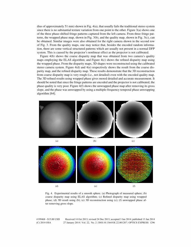
dius of approximately 51 mm) shown in Fig. 4(a), that usually fails the traditional stereo systemsince there is no substantial texture variation from one point to the other. Figure 3(a) shows oneof the three phase-shifted fringe patterns captured from the left camera. From three fringe pat-terns, the wrapped phase map, shown in Fig. 3(b), and the quality map, shown in Fig. 3(c), canbe obtained. Similar images were also obtained for the right camera shown in the second rowof Fig. 3. From the quality maps, one may notice that, besides the encoded random informa-tion, there are some vertical structured patterns which are usually not present in a normal DFPsystem. This is caused by the projector’s nonlinear effect as the projector is not calibrated.
Figure 4(b) shows the coarse disparity map that was obtained from two camera’s qualitymaps employing the ELAS algorithm; and Figure 4(c) shows the refined disparity map usingthe wrapped phase. From the disparity maps, 3D shapes were reconstructed using the calibratedstereo camera system. Figure 4(d) and 4(e) respectively shows the result from the coarse dis-parity map, and the refined disparity map. These results demonstrate that the 3D reconstructionfrom coarse disparity map is very rough (i.e., not detailed) even with the encoded quality map.The 3D refined results using wrapped phase gives mored detailed and accurate measurement. Itshould be noted that since the fringe patterns are encoded and the projector is not calibrated, thephase quality is very poor. Figure 4(f) shows the unwrapped phase map after removing its grossslope, and the phase was unwrapped by using a multiple-frequency temporal phase unwrappingalgorithm [64].
(a) (b) (c)
(d) (e) (f)
Fig. 4. Experimental results of a smooth sphere. (a) Photograph of measured sphere; (b)coarse disparity map using ELAS algorithm; (c) Refined disparity map using wrappedphase; (d) 3D result using (b); (e) 3D reconstruction using (c); (f) unwrapped phase af-ter removing gross slope.
#199468 - $15.00 USD Received 14 Oct 2013; revised 24 Dec 2013; accepted 3 Jan 2014; published 13 Jan 2014(C) 2014 OSA 27 January 2014 | Vol. 22, No. 2 | DOI:10.1364/OE.22.001287 | OPTICS EXPRESS 1296
To further demonstrate the differences among these different approaches for smooth sphericalsurface measurement, we performed further analysis. Since the projector was not directly cali-brated throughout the whole experiments, the 3D result from the conventional reference-plane-based method cannot achieve the same measurement accuracy as the stereo-based method. Ourextensive experimental evaluation found that the reference-plane-based method provides betterresult than the projector-calibration method such as the one we developed [28]. This is proba-bly because the baseline of the camera and the projector [Fig. 2] is very small (approximately25 mm), making the projector calibration inaccurate and thus reducing 3D shape measure-ment accuracy. Therefore, even though the reference-plane-based method cannot provide greatmeasurement accuracy, we still chose this method as a comparison.
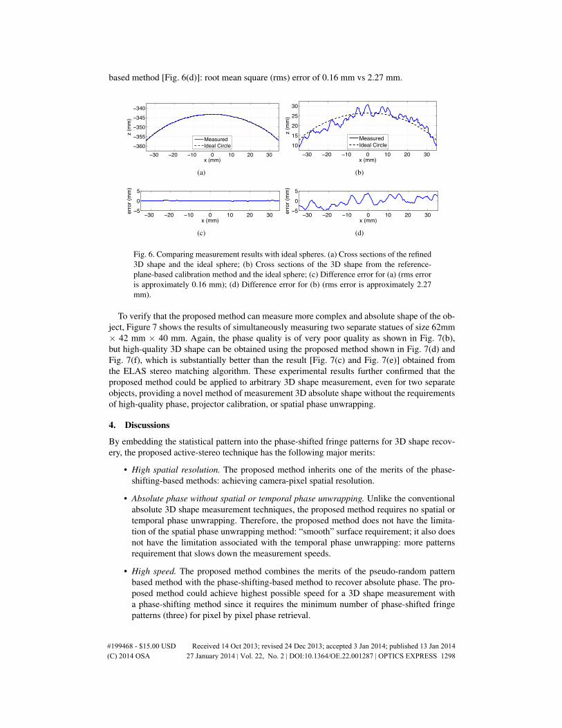
To compare them fairly, the sphere was normalized to reflect the relative error rather thanabsolute error for all these results, as illustrated in Fig. 5. Figure 5(a) shows the normalizedcross-section of the 3D result shown in Fig. 4(d); Figure 5(b) shows the same normalized cross-section of the 3D result shown in Fig. 4(e); and Figure 5(c) shows the normalized cross-sectionof the 3D result shown in Fig. 4(f).
Since the spherical surface we measured is smooth, we then fit these curves with smoothcurve to determine the error between the normalized 3D results and the smoothed ones. Fig-ures 5(d)-5(e) show the results. It should be noted the scale on Fig. 5(f) is 10 times that ofFig. 5(d) and Fig. 5(e). These data clearly demonstrate that even from the poor quality of thephase, the high-quality 3D shape can still be properly reconstructed with the proposed method.This is the because, unlike a single camera DFP system where 3D information is directly ex-tracted from phase, the proposed stereo system only uses the phase as a reference constraint toestablish correspondence.
0 0.5 1 1.50.20.40.60.81
(a)
0 0.5 1 1.50.20.40.60.81
(b)
0 0.5 1 1.50.20.40.60.81
(c)
0 0.5 1 1.5−0.02
0
0.02
(d)
0 0.5 1 1.5−0.02
0
0.02
(e)
0 0.5 1 1.5−0.2
−0.1
0
0.1
0.2
(f)
Fig. 5. Surface measurement error for different methods. (a) Normalized cross-section ofthe 3D result shown in Fig. 4(d); (b) Normalized cross-section of the 3D result shown inFig. 4(e); and (c) Normalized cross-section of the 3D result shown in Fig. 4(f); (d)-(f) showsthe difference between the 3D result with the fitted smooth surface.
To evaluate their accuracy, the measured results were compared against the ideal sphere.Figure 6 shows the comparing results for the refined 3D shape [Fig. 6(a)] and the 3D shapefrom the standard reference-plane-based calibration method [Fig. 6(b)]. It clearly shows thatthe proposed method [Fig. 6(c)] is substantially more accurate than the standard reference plane
#199468 - $15.00 USD Received 14 Oct 2013; revised 24 Dec 2013; accepted 3 Jan 2014; published 13 Jan 2014(C) 2014 OSA 27 January 2014 | Vol. 22, No. 2 | DOI:10.1364/OE.22.001287 | OPTICS EXPRESS 1297
based method [Fig. 6(d)]: root mean square (rms) error of 0.16 mm vs 2.27 mm.
−30 −20 −10 0 10 20 30−360−355−350−345−340
x (mm)
z (m
m)
MeasuredIdeal Circle
(a)
−30 −20 −10 0 10 20 301015202530
x (mm)
z (m
m)
MeasuredIdeal Circle
(b)
−30 −20 −10 0 10 20 30−5
05
x (mm)
erro
r (m
m)
(c)
−30 −20 −10 0 10 20 30−5
05
x (mm)
erro
r (m
m)
(d)
Fig. 6. Comparing measurement results with ideal spheres. (a) Cross sections of the refined3D shape and the ideal sphere; (b) Cross sections of the 3D shape from the reference-plane-based calibration method and the ideal sphere; (c) Difference error for (a) (rms erroris approximately 0.16 mm); (d) Difference error for (b) (rms error is approximately 2.27mm).
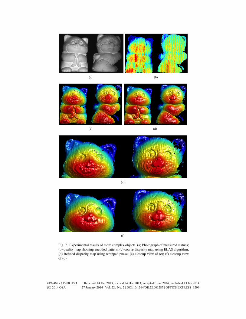
To verify that the proposed method can measure more complex and absolute shape of the ob-ject, Figure 7 shows the results of simultaneously measuring two separate statues of size 62mm× 42 mm × 40 mm. Again, the phase quality is of very poor quality as shown in Fig. 7(b),but high-quality 3D shape can be obtained using the proposed method shown in Fig. 7(d) andFig. 7(f), which is substantially better than the result [Fig. 7(c) and Fig. 7(e)] obtained fromthe ELAS stereo matching algorithm. These experimental results further confirmed that theproposed method could be applied to arbitrary 3D shape measurement, even for two separateobjects, providing a novel method of measurement 3D absolute shape without the requirementsof high-quality phase, projector calibration, or spatial phase unwrapping.
4. Discussions
By embedding the statistical pattern into the phase-shifted fringe patterns for 3D shape recov-ery, the proposed active-stereo technique has the following major merits:
• High spatial resolution. The proposed method inherits one of the merits of the phase-shifting-based methods: achieving camera-pixel spatial resolution.
• Absolute phase without spatial or temporal phase unwrapping. Unlike the conventionalabsolute 3D shape measurement techniques, the proposed method requires no spatial ortemporal phase unwrapping. Therefore, the proposed method does not have the limita-tion of the spatial phase unwrapping method: “smooth” surface requirement; it also doesnot have the limitation associated with the temporal phase unwrapping: more patternsrequirement that slows down the measurement speeds.
• High speed. The proposed method combines the merits of the pseudo-random patternbased method with the phase-shifting-based method to recover absolute phase. The pro-posed method could achieve highest possible speed for a 3D shape measurement witha phase-shifting method since it requires the minimum number of phase-shifted fringepatterns (three) for pixel by pixel phase retrieval.
#199468 - $15.00 USD Received 14 Oct 2013; revised 24 Dec 2013; accepted 3 Jan 2014; published 13 Jan 2014(C) 2014 OSA 27 January 2014 | Vol. 22, No. 2 | DOI:10.1364/OE.22.001287 | OPTICS EXPRESS 1298
(a) (b)
(c) (d)
(e)
(f)
Fig. 7. Experimental results of more complex objects. (a) Photograph of measured statues;(b) quality map showing encoded pattern; (c) coarse disparity map using ELAS algorithm;(d) Refined disparity map using wrapped phase; (e) closeup view of (c); (f) closeup viewof (d).
#199468 - $15.00 USD Received 14 Oct 2013; revised 24 Dec 2013; accepted 3 Jan 2014; published 13 Jan 2014(C) 2014 OSA 27 January 2014 | Vol. 22, No. 2 | DOI:10.1364/OE.22.001287 | OPTICS EXPRESS 1299
• No nonlinear gamma correction requirement. Unlike the conventional phase-basedmethod where the nonlinear gamma correction is usually required, the proposed methoddoes not have to correct the nonlinear gamma of the projector.
• No projector calibration requirement. The proposed method completely eliminates therequirement of projector calibration, which is usually not easy and difficult to achievehigh accuracy for high-speed 3D shape measurement cases. Since no projector calibra-tion is required, the projection system could be simplified (e.g., using an inexpensiveprojection engine, or even a simple slide projector).
• No high-quality phase requirement. This paper demonstrates that high-quality 3D shapemeasurement can be realized even with very poor quality phase data, alleviating the strin-gent requirements of the conventional high-quality 3D shape measurement with phase-based methods. This could further simplify the 3D shape measurement system develop-ment since the projection noise or the camera noise will not substantially influence themeasurement quality.
Yet, the proposed method also has some sacrifices. The major drawbacks associated with theproposed method are:
• Low SNR. It reduces the fringe quality (SNR) by encoding the statistical pattern to thequality map, making it difficult to directly use phase maps to recover 3D shape withoutstereo cameras.
• More computational cost. Comparing with the standard stereo-based method, or phase-based method, the computation time is quite significant due to the pixel-by-pixel disparityrefinements besides the stereo matching time cost.
• Large shade/occlusion areas. The proposed techniques uses the hardware systems in-cludes two cameras and one projector. Theoretically, the system can be constructed intodual camera-projector, structured-light 3D shape system that could enlarge the measure-ment range in a similar manner to the one we have developed before [65]. The proposedmethod, however, only performs 3D shape measurements where three sensors (two cam-eras and one projector) can all see, or the overlapping area of the 3D sensors, and thusthe whole measurement areas are smaller than either structured light system.
Despite these shortcomings, the values of the proposed method are still substantial for high-speed and high-spatial resolution measurements without using expensive hardware compo-nents. This is because the proposed technique uses a phase-based method, and simultaneouslyalleviates the stringent requirements of the conventional phase-based methods.
5. Summary
This paper has presented a novel method for 3D absolute shape measurement without a tradi-tional spatial or temporal phase unwrapping algorithm. We proposed to encode the quality mapof the phase-shifted fringe patterns for rough disparity map determination by employing theELAS algorithm, and the wrapped phase to refine the rough disparity map for high-quality 3Dshape measurement. The proposed method also does not require any projector calibration, orhigh-quality phase map, and thus could potentially simplify the 3D shape measurement systemdevelopment. Experimental results demonstrated the success of the proposed technique.
#199468 - $15.00 USD Received 14 Oct 2013; revised 24 Dec 2013; accepted 3 Jan 2014; published 13 Jan 2014(C) 2014 OSA 27 January 2014 | Vol. 22, No. 2 | DOI:10.1364/OE.22.001287 | OPTICS EXPRESS 1300

Acknowledgment
This study was sponsored by the National Science Foundation (NSF) under grant numbers:CMMI-1150711 and CMMI-1300376. The views expressed in this chapter are those of theauthors and not necessarily those of the NSF.
#199468 - $15.00 USD Received 14 Oct 2013; revised 24 Dec 2013; accepted 3 Jan 2014; published 13 Jan 2014(C) 2014 OSA 27 January 2014 | Vol. 22, No. 2 | DOI:10.1364/OE.22.001287 | OPTICS EXPRESS 1301