abstract - ircobi
TRANSCRIPT
Abstract Children aged around 10 years old (10 YO) are not as well protected as those below 6YO or adults
in traffic accidents. To improve the protective means for occupant and pedestrian in this age group, it is
imperative to enhance the research techniques. To overcome the limitations of testing post‐mortem human
subject (PMHS) or crash dummy, a whole‐body pediatric finite element (FE) model (named CHARM‐10) with
anatomic details and reasonable biofidelity was developed. The model development and validation at
component/body part level have been reported elsewhere and are briefly summarized in this paper. In this
study, the integration of three main body regions (head‐neck, thorax‐upper extremities and pelvis‐lower
extremities) are described in detail. CHARM‐10 has two postures (standing and seated) to represent a pediatric
pedestrian and seated occupant, respectively. The standing posture model was used to corroborate the
kinematic responses in car‐to‐pedestrian impact by comparing kinematics with a newly scaled 10 YO multi‐body
model. The seated posture model was validated against low‐speed volunteer sled tests and a high‐speed PMHS
sled test data. In both pedestrian and occupant impact scenarios, reasonable agreements were obtained. The
CHARM‐10 models were therefore preliminarily validated but require further improvement before applications
in automotive safety research.
Keywords finite element method, occupant impact, pedestrian impact, pediatric human model, traffic injury
I. INTRODUCTION
Road traffic related injuries and fatalities constitute a major daily public safety threat to children all over the
world. In United Sates, it is the leading cause of death and disability for children based on data reported by
Centers for Disease Control and Prevention (CDC) in 2010 [1]. Worldwide, traffic accident is also a top risk to
children aged 4‐15, in which about one‐third of the deaths are to pedestrians, while two‐thirds are to vehicle
occupants [2]. Traffic injuries of children around 10 (8‐12) years old (YO) should be paid particular attention,
according to a review by Wazana et al. (1997) [3]. In 2012, the age group 8‐14 accounted for the largest number
of pedestrian fatalities among all ages of children [4]. In terms of occupant safety, motor vehicle restraint
systems are not specifically designed for children around 10 YO. Most child occupants in this age group are
transiting from using boosters to barely fitting in to seat belts, which are optimized for adult occupants.
Additionally, they usually do not benefit from airbag when sitting in the rear rows and are even harmed by
airbag when seated in the front seats [1].
In terms of pedestrian safety, the age group with the peak injury risk is between 6 and 10 years, as reported by
NHTSA in: (1) Pedestrian injury Causation Study (PICS, 1977 to 1980) and (2) Pedestrian Crash Data Study (PCDS,
1955 to 1998) [5]. The pedestrian fatalities of age group 8‐14 years accounted for more than the summation of
the other child age groups [6]. Therefore, more in‐depth studies on both pedestrian and occupant safety of
children aged 8‐12 years are demanded in order to better understand the injury mechanisms during impact
accidents and to improve safety countermeasures.
Ming Shen is a PhD student in Bioengineering Center of Wayne State University, Detroit, US. (The corresponding author is King H. Yang, Prof. Phone: +1(313)577‐0252, Email: [email protected].) All authors are from this department, except Jiang from Hunan University, Changsha, China. Chou is Prof. Zhu and Jin are Assistant Prof. Jiang is post‐doc fellow. Kalra is a PhD student and others are M.S. students at the time of the study.
Ming Shen1, Feng Zhu, Binhui Jiang, Vikas Sanghavi, Haonan Fan, Yun Cai, Zhenguang Wang, Anil Kalra,
Xin Jin, Clifford C. Chou, King H. Yang
Development and a Limited Validation of a Whole‐Body Finite Element
Pedestrian and Occupant Models of a 10‐Year‐Old Child
IRC-15-73 IRCOBI Conference 2015
- 672 -

Co
te
is
sc
m
im
us
st
af
su
ch
10
m
M
In
W
Co
Ye
do
m
G
Th
m
Fi
m
Fo
im
th
fr
w
ex
an
onventional
ests, anthrop
extremely
cattered. ATD
metallic tubes
mprovement
sually includ
traightforwar
foremention
upplement t
hildren [7, 8]
0 YO [9, 10]
most common
Models Conso
n this study,
Wayne State
ollaborative
ears Old (CH
ocumented
model are em
Geometric da
he model de
meshing, as sh
Medical I
g. 1: Develo
magnetic reso
or establishi
mages from t
he geometry
om 9.5‐10.5
with all perso
xternal body
nd the mean
methodolog
pometric test
difficult to
Ds, such as
s for long bo
if injury me
de multi‐bod
rd kinematic
ed limitatio
hese tests a
], while othe
. However, t
n whole‐bod
ortium (GHB
a 10 YO wh
University (
Safety Rese
HARM‐10).Th
in the literat
mphasized.
ata and mesh
evelopment p
hown in Fig.
Images
opment proc
onance imag
ng high‐qua
two subjects
y. The image
5 YO. An Inst
onal identitie
y dimensions
n weight wa
gies employe
t devices (AT
conduct a la
Hybrid III cr
nes and rub
echanisms a
dy modeling
c and dynam
ons, FE mod
nd simulatio
er researcher
to date, a fu
y FE model f
MC) do not i
hole‐body pe
(WSU). This
arch Center
he developm
ture [11‐15]
h generation
procedure in
1. It is summ
cedures of t
ing (MRI) sca
ality geomet
s (one for CT
e data were
titutional Re
es removed.
s reported by
as 33.1±6.6
CAD
ed in the traf
TDs) tests an
arge numbe
ash dummie
ber jacket fo
nd tolerance
g and finite
mic analysis,
deling has b
ons. Some re
rs have creat
ll body FE m
families of To
nclude a 10
ediatric FE m
10 YO pedi
(CSRC) and
ment and val
. In this stud
II. MODE
n
ncluded two
marized as fo
CAD
he CHARM‐1
ans
tric referenc
and one for
collected fro
view Board
The geome
y Snyder et a
6 kg. In Phas
D modeling
ffic injury stu
nd computat
er of pediatr
es, are made
or torso flesh
es are to be
element (F
but also suf
been widely
esearchers ha
ted FE mode
model repres
otal Human M
YO model.
model with s
iatric FE mo
named Colla
idation work
dy, integratio
EL DEVELOPM
main steps:
ollows.
model
10. Medical
es, two pha
r MRI) per bo
om the Child
at Wayne St
etry was the
al. (1977) [16
se Two, add
Mesh
udies include
ional simula
ric PMHS te
e from artifi
h. Therefore,
investigated
FE) modeling
fers from th
y accepted
ave develop
els for a num
senting child
Model for Sa
sufficient an
odel was dev
aborative Hu
k of the maj
on and preli
MENT METHO
(1) compute
images incl
ases of effor
ody region w
dren's Hospi
tate Univers
n scaled to
6], in which t
itional sets o
hing
e post‐morte
tions. Due to
ests. Conseq
cial and sim
the biofidel
d in detail. C
g. Multi‐bod
e over‐simp
as a major
ed whole‐bo
mber of body
dren around
afety (THUMS
atomic deta
veloped in c
uman Advanc
jor body reg
minary valid
ODS
er aided desig
FE mo
udes compu
rt were mad
were used to
ital of Michi
sity approved
an average‐s
the mean sta
of image da
em human s
o ethical con
uently, data
mplified struc
ity of the AT
Computation
dy modeling
lification. To
r alternative
ody FE mode
y parts for ch
10 YO is sti
S) and Globa
ils has been
collaboratio
ced Researc
gions were c
dations of th
gn (CAD) mo
odel
uted tomogr
de. In Phase
create an in
igan, involvin
d the use of
size 10 YO c
ature was 1.
ata from 94
ubject (PMH
nsiderations,
a are rare a
ctures, such
TDs need mu
nal simulatio
g is suited f
o eliminate t
e approach
els for young
hildren arou
ll missing. T
al Human Bo
n developed
n with Toyo
h Models –
completed a
he whole‐bo
odeling and (
raphy (CT) a
e One, clinic
itial dataset
ng 12 childr
f these imag
child based o
377±0.063
subjects (5‐
HS)
, it
nd
as
ch
ons
for
he
to
ger
nd
he
dy
at
ota
10
nd
dy
(2)
nd
cal
of
en
ges
on
m
29
IRC-15-73 IRCOBI Conference 2015
- 673 -

subjects per body region) were used to verify and adjust the dimensions of skeletal components. The selected
subjects were with an average stature of 1.403±0.091 m and an average weight of 37.6±9.9 kg. Surface
contours of major body parts were created using a commercially available image processing software, Mimics (v.
10) (Materialise, Leuven, Belgium) and assembled to form the whole‐body CAD model. Some structures, such as
ligaments were based on the sites of insertion and origin described in anatomy resources [17, 18] because
clinical images lacked the needed clarities. Detailed descriptions of the CAD modeling was documented in [19].
The stature and weight for the current CHARM‐10 (standing) is 1401 mm and 35.0 kg, respectively.
In the process of meshing, the CAD model was further converted to mesh elements. ANSYS ICEM CFD (v. 12.1)
(ANSYS, Canonsburg, PA) was used to generate hexahedral meshes based on a multi‐block meshing scheme. This
scheme is aimed at producing hexahedral elements in three‐dimensional (3D) space, based on rules for
geometrical grid‐subdivisions (i.e. blocks) and mapping techniques [20]. Using this approach, the mesh size can
be changed by altering the parameters of blocks while the shape remaining unchanged. Some complex cavities
with soft tissues were enclosed and filled with tetrahedral elements, using the tetra‐meshing tool in HyperMesh
(v. 10.0) (Altair, Troy, MI). LS‐DYNA (v.971) (LSTC, Livermore, CA) was used for FE simulations and analyses.
The main development task was divided into three parallel subtasks, i.e. the sub‐models of head‐neck,
thorax‐upper extremities (torso) and pelvis‐lower extremities (PLEX) were developed in parallel. The general
criteria used to determine the overall mesh qualities are as follows: Jacobian value larger than 0.3, aspect ratio
less than 5.0, warpage less than 50° and skew less than 60°.
Material model and properties
The material properties of each body component were taken from open literature and documented in [11‐15].
The material models and their parametric values are briefly summarized in Table 1.
TABLE 1
SUMMARY OF MATERIAL MODEL AND PARAMETERS
Part Material model Element
property Material parameters Reference
CHARM‐10
paper
Cortical:
Cervical Spine
Elastic‐plastic
with power law
Shell,
t=0.265
mm
E=13.44 GPa, k=355 MPa, N=0.277 [21] [11]
Cortical: Rib,
Sternum Elastic‐plastic
Shell,
t=0.57 mm E=6.48 GPa; σY=64.6 MPa
Range from
literatures [14]
Cortical:
Pelvis Elastic‐plastic
Shell,
t=1.6 mm E=12.24 GPa; σY=150 MPa [22] [15]
Cortical:
lower limb
Long bones
Elastic‐plastic
Shell at
epiphysis;
solid at
diaphysis
E: from 0.854 GPa (femoral head)
to 14.9 (tibia shaft) GPa [23, 24] [15]
Trabecular:
Cervical spine
Elastic‐plastic
with power law Solid E=241 MPa, k=5.73 MPa, N=0.274 [25] [11]
Trabecular:
Rib, Sternum Elastic‐plastic Solid E=252.4 MPa, σY=3.52 MPa
Range from
literatures [14]
Trabecular:
Pelvis Elastic‐plastic Solid E=44.8 MPa, σY=7.5 MPa [22] [15]
Trabecular: Elastic‐plastic Solid E: 250 MPa (distal femur) to 770 [23, 24] [15]
IRC-15-73 IRCOBI Conference 2015
- 674 -
Lower limb
long bones
MPa (femoral head)
Cartilage:
Facet Elastic Solid E=10 MPa [26] [11]
Cartilage:
Costal Elastic Solid E=3.3 MPa
Range from
literatures [14]
Cartilage:
Pubic
symphysis
Hyperelastic Solid
Mooney‐Rivlin parameters:
G=0.5MPa C10=0.05 MPa, C01=0.2
MPa, C11=0.25 MPa
[27] [15]
Growth plate:
Cervical spine Elastic Solid E=25 MPa [28] [11]
Vertebral
Endplate
Elastic‐plastic
with power law
Shell,
t=0.45mm E=4.48 GPa; k=118 MPa, N=0.277 [25] [11]
Intervertebral
Nucleus Fluid Solid K=1.72 GPa [29] [11]
Lung Lung tissue Solid K=50 MPa, C=3.88×10⁷, α=5.85,
β=‐3.21, C1=1.265×10‐8, C2=2.71 [30, 31]
[14]
Heart Viscous‐elastic Solid K=2.6 MPa, G0=0.44 MPa,
G∞=0.15 MPa [14]
Skin Elastic Membrane,
t=1mm E=1.0 MPa [32] [15]
Ligaments at
cervical spine Non‐linear Bar Loading curves applied [33] [11]
Ligaments at
pelvis Linear Bar Tensile constants applied [34, 35] [15]
Notes: t: thickness; E: Young's modulus; k: strength coefficient; N: hardening coefficient; σY: yield stress; K: bulk modulus.
The other parameters are material coefficients in unit system: kg‐mm‐ms.
Model Validations at component/body part level
After meshing all body parts, validations of aforementioned three sub‐models were conducted and documented
in [11‐15]. Table 2 summarizes these validations, including body part, loading condition, basic information of
tested subjects and the references for the tests and model development/validation studies. If direct validation
against pediatric subjects was not capable, adult data were used with a certain scaling laws.
TABLE 2
SUMMARY OF THE VALIDATIONS AT COMPONENT OR BODY PART LEVEL
Sub‐model Body part Loading condition Subjects tested References
for tests
References for
CHARM‐10
Head‐neck
Head Frontal impact Adult PMHS [36] Appendix A
Neck
(segments)
Tension, flexion and
extension
Pediatric PMHS
Adult PMHS (scaled)
[37‐39];
[40] [11]
Neck
(whole cervical
spine)
Tension, flexion and
extension Pediatric PMHS [38, 41] [11]
Neck
(whole cervical Low‐speed sled test Pediatric volunteer [42, 43] [12]
IRC-15-73 IRCOBI Conference 2015
- 675 -

W
At
ex
Fi
he
te
A
st
bo
th
us
of
Torso
PLEX
Whole‐body m
t the integr
xtremities) a
g. 2: Model
ead‐neck an
etrahedral el
ll previous m
trategies of
oundary, a st
he connectio
sed. For exam
f the head
spine)
Thorax
Thorax
Abdomen
Thorax
Pelvis
Pelvic girdle
Femur, T
Fibula
Thigh, leg
Knee
model integr
ration stage
nd PLEX (pe
(a)
integration.
nd torso su
ements) dur
meshed part
integration f
trip of trilate
on of attachi
mple, the in
‐neck sub‐m
CPR
poste
comp
Belt
Belt
Fron
impa
Later
e Later
aceta
Tibia, 3‐po
3‐po
(dyn
4‐po
(dyn
ration
, the three
lvis‐lower ex
(a) Division o
ub‐models in
ring torso an
ts were in t
for different
eral element
ng 3D parts
ferior surfac
model, was
(Ant
erior
pression)
loading
loading
tal pendu
act
ral plate imp
ral impact
abulum
int bending
int bending
amic)
intbending
amic)
developed
xtremities) w
of three sub‐
ntegration (
d PLEX sub‐m
he same an
t body regio
ts was built t
with differe
ce of the inte
tied to th
terior
Pedia
Pedia
Pedia
ulum Pedia
pact Pedia
to Adult
(Resu
Pedia
Adult
(Resu
Adult
(Resu
and validat
were integrate
(b)
‐models dev
(rear view);
models integ
natomical po
ons are desc
to connect t
ent mesh de
ervertebral d
he superior
atric patients
atric PMHS
atric PMHS
atric PMHS
atric PMHS
t PMHS
ults scaled)
atric PMHS
t PMHS
ults scaled)
t PMHS
ults scaled)
ted sub‐mod
ed into a wh
veloped in pa
(c) interna
gration (a par
ositions (at s
ribed as foll
he edges wi
nsities, the
disc between
surface of
s
[
[
dels: head‐n
ole‐body mo
arallel; (b) mu
al gaps mer
ra‐sagittal vie
standing pos
lows: (1) Fo
th different
LS‐DYNA key
n C7 and T1
T1 superio
[44]
[45, 46]
[45, 46]
[47]
[48]
[49]
[50]
[51]
[52]
neck, torso
odel, as show
(c)
uscle re‐con
rging and r
ew)
sture) for as
r the surfac
numbers of
yword CONT
vertebrae, w
or endplate
[14]
[13]
Appendix B
[13]
[15]
[15]
[15]
[15]
[15]
(thorax‐upp
wn in Fig. 2 (a
nection duri
e‐meshing
ssembling. T
ce through t
nodes. (2) F
TACT_TIED w
which was pa
e. (3) For 1
B
per
a).
ng
(in
he
he
For
was
art
1D
IRC-15-73 IRCOBI Conference 2015
- 676 -

ligament/muscle elements connecting across two sub‐models, the reference nodes temporarily used for
validations of sub‐models were replaced with structural nodes located at identical geometric locations. The
reconnection of muscles at the neck region is shown in Fig. 2 (b) as an illustration. (4) All major viscera (heart,
lungs, kidneys, stomach, etc.) were individually modeled and hence there were gaps among them. Tetrahedral
elements were used to fill these gaps during the sub‐modeling process. In the integration of two adjacent
sub‐models, the gap filling tetra‐meshes in each sub‐model were deleted and then the newly formed space was
refilled with new tetrahedral elements. Fig. 2 (c) showed an example at abdomen region. The general
information of this whole‐body FE model representing a 10 YO child is listed in Table 3.
TABLE 3
CHARM‐10 OVERVIEW (STANDING POSTURE)
Number
of parts
Number
of nodes
Number
of elements
Number of contacts
(including node‐to‐part
constrains)
Hexahedral vs.
Tetrahedral
Quadrilateral vs.
triangle
Original time
step size
993 949,311 1,678,610 212 98.3% vs. 1.7%* 93.5% vs. 6.5% 6.2×10‐5ms
Jacobian < 0.3 Aspect ratio > 5.0 Warpage > 50.0° Skew > 60.0°
2D: 0%
3D: <0.01%
2D: 0.07%
3D: 0.15%
2D: <0.01%
3D: <0.01%
2D: 0.03%
3D: 0.83%
*: The tetrahedral elements at joints regions and internal fat tissue among viscera and inner wall of fleshes were excluded.
III. WHOLE‐BODY MODEL PRELIMINARY VALIDATIONS
Whole‐body pedestrian impact
Since PHMS study was rarely available in literature, a typical car‐to‐pedestrian lateral impact scenario was
created and FE simulations were carried out and compared with the other simulation using multi‐body model. A
detailed small sedan FE model, published on Dec. 21, 2011 was obtained from the National Crash Analysis
Center (NCAC) website. The model was then simplified and only the front portion including the front bumper
and hood, etc. was used to save computational time. A constant speed of 10 m/s (36 km/h) was assigned to the
simplified car model that hit the CHARM‐10 (standing) in lateral direction.
MADYMO (v.7.5) (TASS, Helmond, Netherlands) was used for multi‐body model development and impact
simulation. The 50th percentile MADYMO ellipsoid pedestrian model (v. 5.0) was taken as the baseline model.
MADYMO/Scaler, based on GEBOD population [53], was used to scale the MADYMO baseline model to a 10 YO
multi‐body model with the same height and weight of the CHARM‐10 (1401 mm and 35.0 kg). Using coupling
FE‐multi‐body version of MADYMO, the same car FE model, initial positioning and impact speed used in
CHARM‐10 pedestrian impact simulation were adapted in the simulation using 10 YO MADYMO scaled model.
The kinematic results are shown in Table 4.
The comparison shows that, the CHARM‐10 has similar kinematics histories as the 10 YO MADYMO model,
especially on the upper body. However, the lower limbs of CHARM‐10 exhibit more extents of motion off the
bumper from 60 ms. Because the head‐to‐hood impact is the major cause of fatal head/brain injury, the relative
motion of the head to hood is also analyzed. The initial head contact of CHARM‐10 simulation occurs at 85 ms,
while it is 84 ms in the 10 YO MADYMO simulation. The peak velocities of the head center of gravity (CG) in
vertical direction are 7.8 m/s and 8.0 m/s, for the FE and multi‐body models respectively. The comparison
demonstrates that the kinematic responses of the CHARM‐10 (standing) are close to those of multi‐body model,
especially in terms of upper body and head motion.
It should be noted that the 10 YO MADYMO model was generated by scaling an adult pedestrian model to a 10
IRC-15-73 IRCOBI Conference 2015
- 677 -

YO
ch
p
(S
ad
p
(S
ad
M
In
w
hi
co
lig
Th
su
jo
re
Fo
pr
ex
be
O child, whi
heck and kin
Model
10 YO FE
pedestrian
model
10 YO
MADYMO
model
Scaled from
dult model)
Model
10 YO FE
pedestrian
model
10 YO
MADYMO
model
Scaled from
dult model)
Model postur
n order to sim
was accomplis
ip, knee, and
ondyle, and
gaments at t
he outer skin
urface of the
oint region, a
e‐generated.
or sled test s
rocess was d
xported as th
etween the m
ch was not
ematic corro
re change
mulate occu
shed by join
d ankle joint
lateral malle
these joints
n at a joint w
e surroundin
a new enclos
simulations,
done by app
he initial con
model and a
validated. S
oboration, ra
PEDESTRIA
0 ms
60 ms
pant respon
t rotations a
ts were remo
eolus were t
were rebuilt
was morphed
ng flesh/fat w
sed space wa
the spine w
plying presc
ndition for th
verage postu
ubsequently
ather than a c
AN LATERAL IMP
nses, the stan
and spine rep
oved. Skelet
then carried
t according t
d along with t
was also cha
as achieved s
was repositio
ribed motio
he sled test s
ure of volunt
y, the simula
complete va
TABLE 4
PACT SIMULAT
20
80
nding postu
positioning.
tal rotations
out in sequ
to the norma
the rotation
anged. Using
so that tetra
ned to follow
ons to the h
simulations.
teers tested.
ation study s
lidation.
TION RESULT CO
ms
ms
re model wa
Firstly, the te
about the c
ence at thes
al physiologi
using Hyper
g the adjuste
hedral elem
w the curvat
head, C4, T1
As shown in
should be co
OMPARISON
as converted
etra meshes
enter of fem
se three join
cal state in a
rMopher too
ed outer skin
ents for flesh
ture describe
, T4 and T8
n Fig. 3, little
onsidered as
40 ms
100 ms
d to a seated
and ligamen
moral head, l
nts. After the
a seated pos
ol of HyperM
n and inner
h/fat at the j
ed in [54]. T
8. The final
e discrepanci
s a robustne
s
d posture. Th
nts around t
lateral femo
e rotation, t
sition [17, 18
Mesh. The inn
surface at t
joints could
The positioni
geometry w
es were fou
ess
his
he
ral
he
8].
ner
he
be
ng
was
nd
IRC-15-73 IRCOBI Conference 2015
- 678 -

Fi
D
CH
el
th
W
Th
fr
ch
Inmonsaretr
Fi(a
g. 3: Model
uring the po
HARM‐10 se
lements faile
he percentag
Whole‐body o
he seated m
ontal car cra
hild PMHS [5
INFORMATIO
Reference
Arbogast etal. 2009 [54
Ash et al. 2009 [55]
n both scenamounted on an selected boagittal planeespectively. Irajectories w
g. 4: Experiadapted from
posture chan
osture chang
eated postur
ed for skew a
ges of eleme
occupant sle
odel was use
ashes, name
55]. The infor
ON OF THE SUB
Subjec
t 4]
6 voluntee
1 PMHS
arios, the sua crash sled,ody location. The experiIt should be
were scaled to
mental setum [54]) and (b
nge result, co
ge, the mes
re was re‐as
angle criterio
nts with low
ed test
ed to predict
ely (1) low‐sp
rmation rega
BJECTS, LOADIN
ct Age (year)
ers
10.2
±0.8
S 13
ubject was p which was ds such as theimental setue noted that o 10 YO and
(a) p and subjeb) high‐spee
ompared wit
h quality wa
ssessed using
on. For all ot
er quality we
t the respons
peed sled te
arding subjec
NG CONDITIONS
) Stature(mm)
8
1378
±92
1390
positioned odecelerated e ear, acromup and subjethe PMHS reported by
ect posture od sled test o
th the averag
as carefully
g the same
ther criteria
ere 0.2% or l
ses in two lo
est on child
cts tested an
TABLE 5
S AND BELT FO
e )
Weigh(kg)
32.3
±5.3
31
on a seat anby a hydrau
mion, iliac creect postures in the high‐the investiga
of the sled ton a 13 YO PM
ge posture o
controlled.
criteria liste
such as Jaco
less. The orig
oading condi
volunteers [
d loading co
RCE OUTPUTS O
ht
Impaveloc(m/
3
3 2.32±
11.
d restrainedulic system (pest and knee of the two speed test wators in [55].
tests: (a) lowMHS (adapte
f seated volu
After this ph
ed in Table 3
obian, warpa
ginal time ste
tions which
[54] and (2)
nditions are
OF SLED TESTS
act city s)
Pdece
0.14 3.62
4
d by a threepulse generato trace the tests are shwas a 13 YO.
(bw‐speed sleded from [55])
unteer in [54
hase, the m
3. A total o
age angle an
ep stays unc
were design
high‐speed
summarized
(±STANDARD
Peak eleration (g)
d
2±0.29
~22
e‐point belt. ator). Marker kinematic rehown in Fig. O, and the b
b) d test on ch)
4].
mesh quality
f 0.85% of 3
d aspect rat
hanged.
ed to simula
sled test on
d in Table 5.
D DEVIATION)
Duration of deceleration
(ms)
~125
~70
The seat wrs were placesponse in t4 (a) and (b
belt forces a
hild voluntee
of
3D
io,
ate
n a
was ed he b), nd
ers
IRC-15-73 IRCOBI Conference 2015
- 679 -
Inthsehisecobe
Inushianenel
Mtyprroushi
Thpolotetrsh
Fi
Th
th
in
H
st
fr
In
th
hi
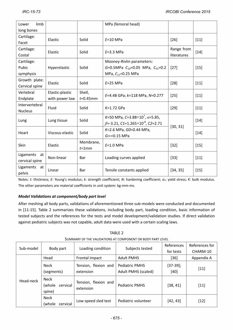
n simulationshree‐point seeat used in [5igh and 18° eat pan and onducted beetween the m
n Arbogast exsing LS_DYNistory reportnchors. The sngaged the tlements of th
Muscles in thype No. 156rocedures tootation time sed in [12] wigh‐speed PM
he same moosture detaiow‐speed sleest was extrrapezoidal frhown in Fig.
g. 5: Simulat
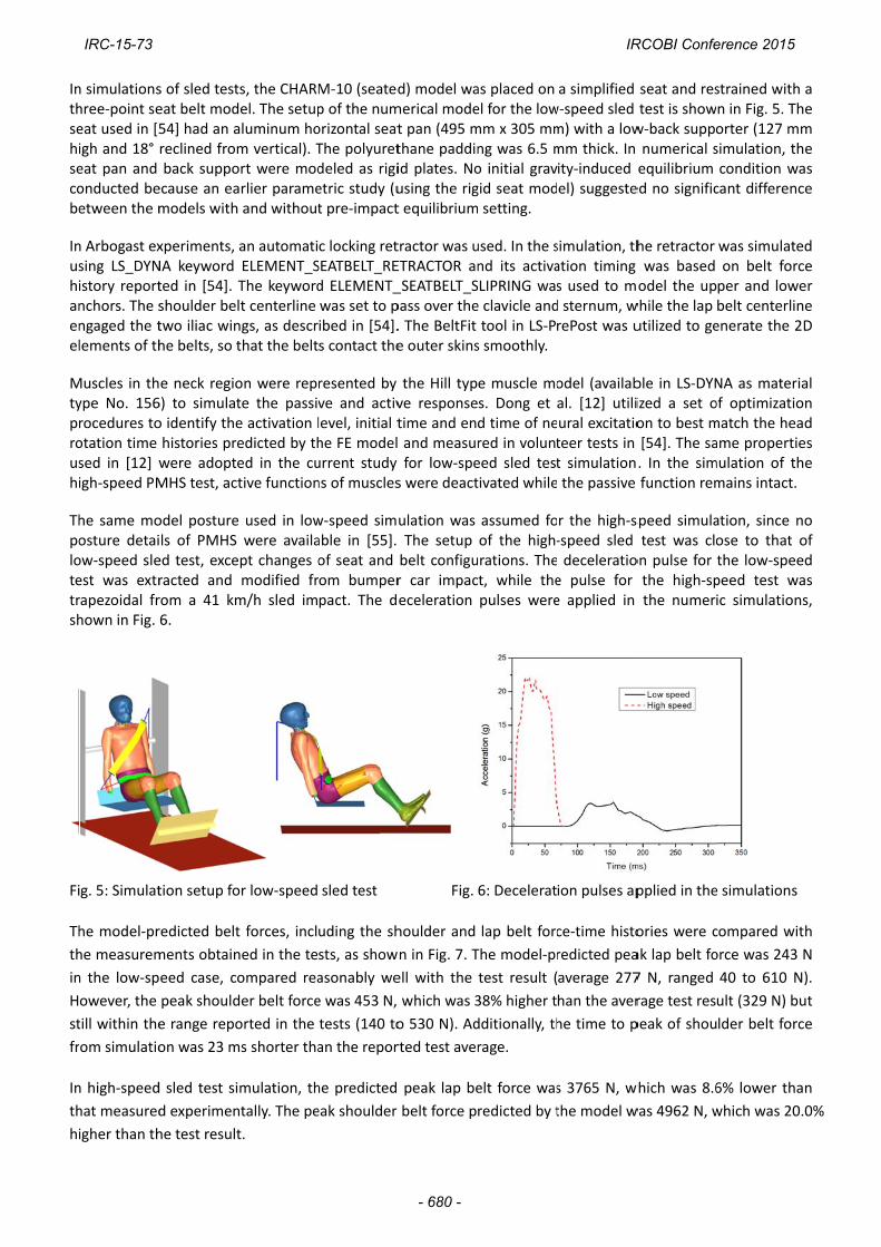
he model‐pr
he measurem
n the low‐sp
owever, the
till within the
om simulatio
n high‐speed
hat measured
igher than th
s of sled testeat belt mod54] had an areclined fromback suppo
ecause an eamodels with
xperiments, NA keyword ted in [54]. Tshoulder beltwo iliac winhe belts, so t
e neck regio6) to simulato identify thehistories prewere adopteMHS test, act
odel posturels of PMHS ed test, exceracted and rom a 41 km6.
tion setup fo
redicted belt
ments obtain
eed case, co
peak should
e range repo
on was 23 m
d sled test si
d experimen
he test result
s, the CHARMel. The setupaluminum hom vertical). Tort were modarlier parameand without
an automatiELEMENT_SThe keywordlt centerline ngs, as descrthat the belt
on were repte the passive activation ledicted by thed in the cutive function
used in lowwere availapt changes omodified frm/h sled im
or low‐speed
t forces, incl
ned in the te
ompared rea
der belt force
orted in the
ms shorter tha
mulation, th
ntally. The pe
t.
M‐10 (seatedp of the numorizontal seatThe polyuretdeled as rigietric study (ut pre‐impact
c locking retSEATBELT_REd ELEMENT_was set to pibed in [54].s contact the
resented by ve and activlevel, initial the FE modelurrent study ns of muscles
w‐speed simable in [55]. of seat and om bumperpact. The d
sled test
uding the sh
sts, as show
asonably we
e was 453 N,
tests (140 to
an the repor
he predicted
eak shoulder
d) model wamerical modet pan (495 mthane paddinid plates. Nousing the rigt equilibrium
tractor was uETRACTOR an_SEATBELT_Spass over the. The BeltFit e outer skins
the Hill typve responsetime and en and measurfor low‐spe
s were deact
ulation was The setup belt configur car impaceceleration
Fig.
houlder and
n in Fig. 7. T
ell with the
which was 3
o 530 N). Ad
rted test aver
peak lap be
belt force p
as placed on el for the lowmm x 305 mmng was 6.5 mo initial gravgid seat mod setting.
used. In the snd its activaSLIPRING wase clavicle andtool in LS‐Ps smoothly.
e muscle mos. Dong et d time of nered in volunteed sled testtivated while
assumed foof the high‐
urations. Thet, while thepulses were
6: Decelerat
lap belt forc
The model‐pr
test result (
38% higher t
dditionally, th
rage.
elt force was
redicted by t
a simplified w‐speed sled m) with a lowmm thick. In ity‐induced el) suggeste
simulation, thation timing s used to md sternum, wrePost was u
odel (availabal. [12] utiliural excitatioteer tests in t simulation the passive
r the high‐s‐speed sled deceleratioe pulse for e applied in
ion pulses ap
ce‐time histo
redicted pea
average 277
han the aver
he time to p
s 3765 N, w
the model w
seat and restest is showw‐back suppo numerical sequilibrium ed no signific
he retractor was based odel the up
while the lap utilized to ge
ble in LS‐DYNized a set oon to best m[54]. The sa. In the simfunction rem
speed simulatest was clo
on pulse for the high‐spthe numeri
pplied in the
ories were c
ak lap belt fo
7 N, ranged
rage test res
peak of shou
which was 8.6
was 4962 N, w
strained withn in Fig. 5. Torter (127 msimulation, tcondition wcant differen
was simulaton belt forper and lowbelt centerlienerate the 2
NA as materof optimizatiomatch the heame propertimulation of tmains intact.
ation, since ose to that the low‐spepeed test wic simulation
e simulations
compared wi
orce was 243
40 to 610 N
ult (329 N) b
lder belt for
6% lower th
which was 20
h a he
mm he
was nce
ed rce wer ne 2D
rial on ad ies he
no of ed
was ns,
s
ith
3 N
N).
but
rce
an
0.0%
IRC-15-73 IRCOBI Conference 2015
- 680 -

Fi
hi
Fo
by
m
re
m
th
Fi
As
ex
Li
In
ex
st
lo
w
Fu
g. 7: Compa
igh‐speed ca
or the low‐sp
y dividing th
model‐predict
eported the
model‐predict
he CHARM‐1
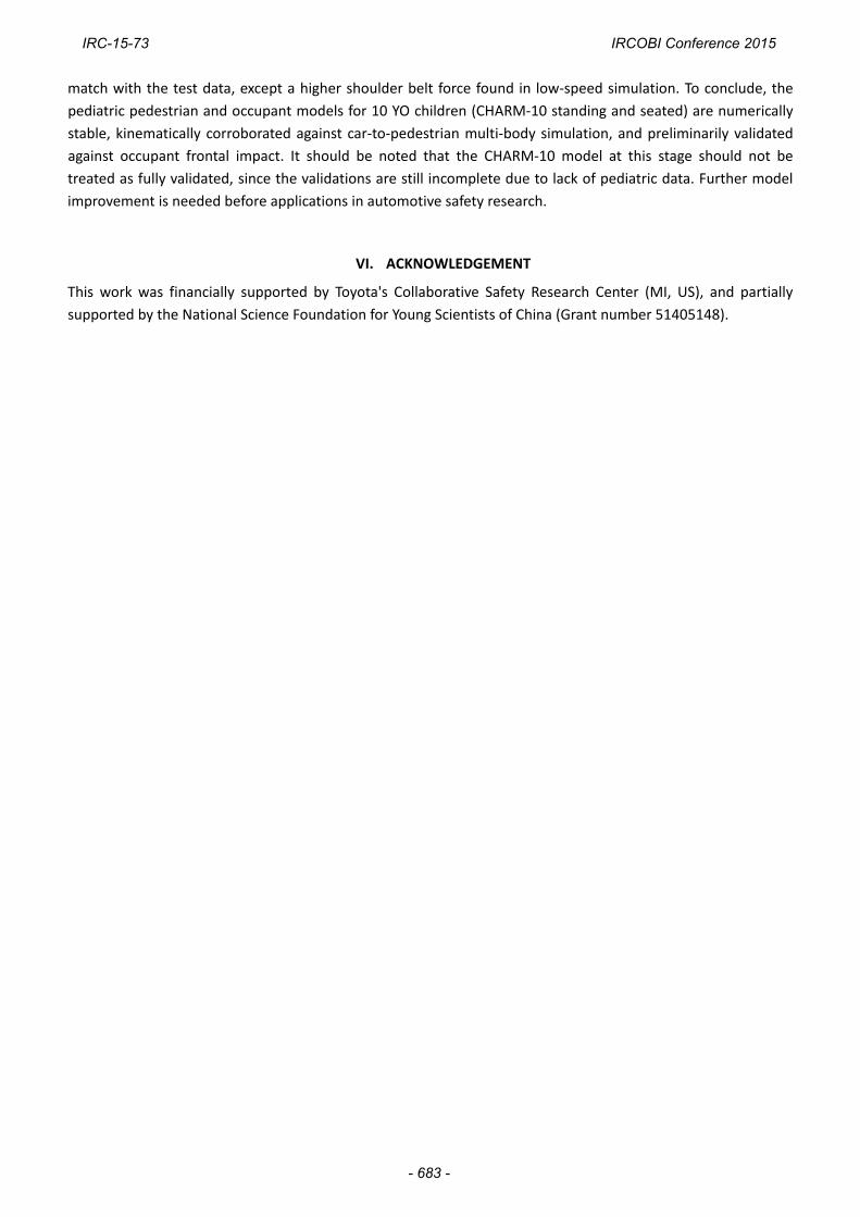
g.8: Compar
sh et al). So
xcursion at th
imitations of
njury related
xample, the
tudy did not
oading condi
were predicte
uture works
(a
arison of the
ase
peed experim
he marker co
ted results
trajectories
ted excursio
0 (seated) m
(a
rison of the
lid curves: t
he posterior
f the whole‐b
validations
3‐point bend
t include inj
tions. Given
ed by the wh
should cons
a)
belt forces
mental studie
oordinates b
and compar
s by scaling
ns was mad
model reason
a)
trajectories:
est results;
‐anterior and
body model
done at com
ding induced
ury predicti
n the fact th
hole‐body mo
sider collecti
predicted by
es, the repor
y the seated
risons plotte
g the exper
e and show
ably match t
: (a) low‐spe
dashed curv
d inferior to
I
validations
mponent lev
d fracture in t
on because
at reasonab
odel, there is
ing fall or tr
y the FE mod
rted excursio
d height. Th
ed in Fig. 8
rimental dat
n in Fig. 8 (b
the kinemati
eed case (no
ves: simulatio
superior dire
IV. DISCUS
vel were rep
the leg, tens
of the pau
ble biomecha
s a good pot
raffic acciden
del and mea
ons were bas
e same norm
8 (a). For th
ta to a 10
b). It was fo
ic results in b
rmalized) an
on results; X
ection, respe
SION
ported in pre
sile ruptures
city of pedia
anical respon
tential that it
nt induced in
(b)
sured by tes
sed on a norm
malization m
e high‐spee
YO [55]. D
und that the
both low‐spe
(b)
nd (b) high‐s
X‐ and Z‐excu
ectively.
evious paper
in the neck l
atric whole‐
nses under v
t can be app
njuries to ch
sts. (a) low‐s
malization p
method was
ed experime
Direct comp
e trajectorie
eed and high
speed case (
ursions are d
rs as listed i
ligaments, et
‐body test d
various load
plied for pred
heck the pot
speed case, (
rocedure do
applied to t
ent, Ash et
parison of t
s predicted
h‐speed tests
scaled data
defined as t
in Table 2. F
tc. The curre
ata in inten
ding conditio
dicting injurie
ential of usi
(b)
ne
he
al.
he
by
s.
by
he
For
ent
nse
ons
es.
ng
IRC-15-73 IRCOBI Conference 2015
- 681 -

CHARM‐10 to predict real world injury. More limitations of each corroboration/validation are stated as follows.
CHARM‐10 (standing) model was corroborated by comparing the kinematics to that calculated by the reference
10 YO MADYMO model developed using a scaling method. Despite the fact that two models were in good
agreement, none of them can be considered validated. At best, the similarities found between two different
models using two different software packages suggest that the kinematic response predicted by CHARM‐10
(standing) model subjected to lateral impact is reasonable.
For CHARM‐10 (seated) low‐speed sled test simulation, the initial positioning, muscle force, and belt model
selected in the whole‐body sled test simulation all contributed to the variation observed in the shoulder belt
force in terms of magnitude and timing. No attempt was made to correct the differences in part because of the
lack of sufficient details listed in the experimental study. Additionally, the model‐predicted peak shoulder force
(453 N) was still within the measured peak shoulder force ranged from 140 to 530 N. No explanations were
provided regarding this large discrepancy in the range obtained experimentally and it would be premature
attempting to correct this difference.
In the high‐speed sled test simulation, the tested subject was a 13 YO with larger anthropometric dimensions
than an average 10 YO child. Although scaled data were reported in the PMHS study paper, details of the seat,
seat belts and precise spinal curvature were not available. For these reasons, some errors may be added to the
simulation.
Future work
For the finished component and sub‐model level validations summarized in Table 2, the loading for lower body
validation are mainly at lateral direction, while those for the torso are mainly at fore‐aft direction. In future, the
CHARM‐10 model should be further validated in more loading conditions. More test data from adults can
potentially be used for model improvement, with careful selection or development of specific scaling laws.
Accident reconstruction is another possible approach to improve the model's capability of injury prediction.
Epiphyseal growth plate is another point of interest. As summarized in [56], earlier epidemiological studies
revealed that 15‐20% of all childhood fractures were growth plate related. These structures typically lie at the
ends of long bones of skeletally immature humans. The mechanical weakening may have significant effect on
the biomechanical responses according to a parametric study [15]. Most growth plates are not modeled in the
current version of CHARM‐10. This is in part due to the fact that biomechanical properties of growth plate are
largely unknown and growth plate injury was not routinely reported in accident database. When human test
data involving growth plates become available, detailed models consist of growth plates could be developed to
achieve a higher biofidelity.
V. CONCLUSIONS
To facilitate the investigation of pediatric injury mechanism and advanced protection techniques, efforts were
devoted to the development of a whole‐body FE model of an average 10 YO child (CHARM‐10) with sufficient
details. The integration of three sub‐models of the head‐neck, torso and PLEX was successfully conducted. Full
body simulations were performed at both standing and seated postures. The simulation results using the
CHARM‐10 (standing) have a reasonable agreement with a multi‐body simulation under the same impact
condition, in terms of motion history and head impact timing and velocity. The simulations of low‐speed and
high‐speed sled tests using the CHARM‐10 (seated) were compared to the experimental data of volunteers and a
PHMS, respectively. The belt force histories and body motions predicted by the FE model showed a satisfactory
IRC-15-73 IRCOBI Conference 2015
- 682 -
match with the test data, except a higher shoulder belt force found in low‐speed simulation. To conclude, the
pediatric pedestrian and occupant models for 10 YO children (CHARM‐10 standing and seated) are numerically
stable, kinematically corroborated against car‐to‐pedestrian multi‐body simulation, and preliminarily validated
against occupant frontal impact. It should be noted that the CHARM‐10 model at this stage should not be
treated as fully validated, since the validations are still incomplete due to lack of pediatric data. Further model
improvement is needed before applications in automotive safety research.
VI. ACKNOWLEDGEMENT
This work was financially supported by Toyota's Collaborative Safety Research Center (MI, US), and partially
supported by the National Science Foundation for Young Scientists of China (Grant number 51405148).
IRC-15-73 IRCOBI Conference 2015
- 683 -

VII. REFERENCES
1. Arbogast, K B, Durbin D R. Epidemiology of child motor vehicle crash injuries and fatalities, Pediatric Injury
Biomechanics. 2013, Springer: 33‐86.
2. WHO. World report on child injury prevention. 2008.
3. Wazana, A, Krueger P, Raina P, Chambers L. A review of risk factors for child pedestrian injuries: are they modifiable?
Injury Prevention, 1997, 3 (4): 295‐304.
4. NHTSA. Traffic Safety Facts 2012 data ‐ Pedestrian. Government Report, 2014 (DOT HS 811 888).
5. Jarrett, K, Saul R. Pedestrian injury‐analysis of the PCDS field collision data. Proceedings of the 16th International
Technical Conference on the Enhanced Safety of Vehicles (ESV), 1998, Windsor, Ontario, CA.
6. NHTSA. Traffic Safety Facts 2011 data ‐ Children. Government Report, 2013 (DOT HS 811 767).
7. Mizuno, K, Iwata K, Deguchi T, Ikami T, Kubota M. Development of a three‐year‐old child FE model. Traffic Injury
Prevention, 2005, 6 (4): 361‐371.
8. Okamoto, M, Takahashi Y, et al. Development of finite element model for child pedestrian protection. Proceedings
of the 18th International Technical Conference on the Enhanced Safety of Vehicles (ESV), 2003, Nagoya, Japan.
9. Ito, O, Okamoto M, Takahashi Y, Mori F. Validation of an FE Lower Limb Model for a Child Pedestrian by Means of
Accident Reconstruction. SAE International Journal of Passenger Cars‐Mechanical Systems, 2009, 1 (1): 971‐984.
10. Kim, J E, Li Z, et al. Finite element model development of a child pelvis with optimization‐based material
identification. Journal of Biomechanics, 2009, 42 (13): 2191‐2195.
11. Dong, L, Li G, Mao H, Marek S, Yang K H. Development and validation of a 10‐year‐old child ligamentous cervical
spine finite element model. Annals of Biomedical Engineering, 2013, 41 (12): 2538‐2552.
12. Dong, L, Mao H, Li G, Yang K H. Investigation of pediatric neck response and muscle activation in low‐speed frontal
impacts. Computer methods in biomechanics and biomedical engineering, 2015 (In press).
13. Jiang, B, Mao H, Cao L, Yang K H. Experimental Validation of Pediatric Thorax Finite Element Model Under Dynamic
Loading Condition and Analysis of Injury. SAE Technical Paper, 2013 (No. 2013‐01‐0456).
14. Jiang, B, Cao L, et al. Development of a 10‐year‐old paediatric thorax finite element model validated against
cardiopulmonary resuscitation data. Computer methods in biomechanics and biomedical engineering, 2014, 17
(11): 1185‐1197.
15. Shen, M, Zhu F, et al. Finite element modeling of 10‐year‐old child pelvis & lower extremities with growth plates
for pedestrian protection. International Journal of Vehicle Safety, 2015 (In press).
16. Snyder, R, Schneider L, et al. Anthropometry of Infants, Children, and Youths to Age 18 for Product Safety Design.
Final Report. Consumer Product Safety Commission Report, 1977 (No. UM‐HSRI‐77‐17).
17. Gray, H. Gray's Anatomy of Human Body. 1918 (Accessed: 2013 Nov. 1st); Available from:
https://education.yahoo.com/reference/gray/subjects/subject/57.
18. Moore, K L, Agur A M R, Dalley A F. Essential clinical anatomy. 4th ed. 2011, Lippincott Williams & Wilkins:
Baltimore, MD.
19. Mao, H, Holcombe S, et al. Development of a 10‐Year‐Old Full Body Geometric Dataset for Computational
Modeling. Annals of Biomedical Engineering, 2014, 42 (10): 2143‐2155.
20. Shivanna, K H, Tadepalli S C, Grosland N M. Feature‐based multiblock finite element mesh generation.
Computer‐Aided Design, 2010, 42 (12): 1108‐1116.
21. Currey, J D. Tensile yield in compact bone is determined by strain, post‐yield behaviour by mineral content. Journal
of Biomechanics, 2004, 37 (4): 549‐556.
22. Kim, J E, Hsieh M H, Soni B K, Zayzafoon M, Allison D B. Childhood Obesity as a Risk Factor for Bone Fracture: A
mechanistic study. Obesity, 2013, 21 (7): 1459‐1466.
23. Takahashi, Y, Kikuchi Y, Konosu A, Ishikawa H. Development and validation of the finite element model for the
human lower limb of pedestrians. Stapp Car Crash Journal, 2000, 44 (1): 335‐355.
24. Untaroiu, C, Darvish K, Crandall J, Deng B, Wang J T. A finite element model of the lower limb for simulating
IRC-15-73 IRCOBI Conference 2015
- 684 -

pedestrian impacts. Stapp Car Crash Journal, 2005, 49 (1): 157‐181.
25. Kopperdahl, D L, Keaveny T M. Yield strain behavior of trabecular bone. Journal of Biomechanics, 1998, 31 (7):
601‐608.
26. Yamada, H, Evans F G. Strength of biological materials. 1970, Williams & Wilkins: Baltimore.
27. Li, Z, Alonso J E, et al. Three‐dimensional finite element models of the human pubic symphysis with
viscohyperelastic soft tissues. Annals of Biomedical Engineering, 2006, 34 (9): 1452‐1462.
28. Cohen, B, Chorney G S, et al. The microstructural tensile properties and biochemical composition of the bovine
distal femoral growth plate. Journal of Orthopaedic Research, 1992, 10 (2): 263‐275.
29. Yang, K H, Zhu F, Luan F, Zhao L, Begeman P C. Development of a finite element model of the human neck. Stapp
Car Crash Journal, 1998, 42: 195‐205.
30. Shah, C S, Yang K H, Hardy W, Wang H K, King A I. Development of a computer model to predict aortic rupture due
to impact loading. Stapp Car Crash Journal, 2001, 45: 161‐182.
31. Ito, O, Dokko Y, Ohashi K. Development of Adult and Elderly FE Thorax Skeletal Models. SAE Technical Paper, 2009
(No. 2009‐01‐0381).
32. Yue, N, Shin J, Untaroiu C D. Development and validation of an occupant lower limb Finite element model. SAE
Technical Paper, 2011 (No. 2011‐01‐1128).
33. Chazal, J, Tanguy A, et al. Biomechanical properties of spinal ligaments and a histological study of the supraspinal
ligament in traction. Journal of Biomechanics, 1985, 18 (3): 167‐176.
34. Hewitt, J, Guilak F, Glisson R, Vail T P. Regional material properties of the human hip joint capsule ligaments.
Journal of Orthopaedic Research, 2001, 19 (3): 359‐364.
35. Bechtel, R. Physical characteristics of the axial interosseous ligament of the human sacroiliac joint. The Spine
Journal, 2001, 1 (4): 255‐259.
36. Nahum, A M, Smith R, Ward C C. Intracranial pressure dynamics during head impact. SAE Technical Paper, 1977
(No. 770922).
37. Luck, J F, Nightingale R W, et al. Tensile mechanical properties of the perinatal and pediatric PMHS
osteoligamentous cervical spine. Stapp Car Crash Journal, 2008, 52: 107‐134.
38. Luck, J F. The biomechanics of the perinatal, neonatal and pediatric cervical spine: investigation. 2012, PhD
Dissertation, Duke University.
39. Luck, J F, Nightingale R W, et al. Tensile failure properties of the perinatal, neonatal, and pediatric cadaveric cervical
spine. Spine, 2013, 38 (1): E1‐E12.
40. Nightingale, R W, Chancey V C, et al. Flexion and extension structural properties and strengths for male cervical
spine segments. Journal of Biomechanics, 2007, 40 (3): 535‐542.
41. Ouyang, J, Zhu Q, et al. Biomechanical assessment of the pediatric cervical spine under bending and tensile
loading. Spine, 2005, 30 (24): E716‐E723.
42. Dibb, A T. Pediatric head and neck dynamic response: A computational study. 2011, PhD Dissertation, Duke
University.
43. Panzer, M B, Fice J B, Cronin D S. Cervical spine response in frontal crash. Medical Engineering & Physics, 2011, 33
(9): 1147‐1159.
44. Maltese, M R, Castner T, et al. Methods for determining pediatric thoracic force‐deflection characteristics from
cardiopulmonary resuscitation. Stapp Car Crash Journal, 2008, 52: 83‐105.
45. Kent, R, Lopez‐Valdes F J, et al. Characterization of the pediatric chest and abdomen using three post‐mortem
human subjects. Proceedings of the 22nd International Technical Conference on the Enhanced Safety of Vehicles
(ESV), 2011, Washington, DC, US.
46. Kent, R, Salzar R, et al. Pediatric thoracoabdominal biomechanics. Stapp Car Crash Journal, 2009, 53: 373‐401.
47. Ouyang, J, Zhao W, Xu Y, Chen W, Zhong S. Thoracic impact testing of pediatric cadaveric subjects. Journal of
Trauma and Acute Care Surgery, 2006, 61 (6): 1492‐1500.
48. Ouyang, J, Zhu Q, et al. Experimental cadaveric study of lateral impact of the pelvis in children. Academic Journal
IRC-15-73 IRCOBI Conference 2015
- 685 -

of the First Medical College of PLA, 2003, 23 (5): 397‐401, 408.
49. Guillemot, H, Besnault B, et al. Pelvis Injuries in Side Impact Collisions : A Field Accident Analysis and Dynamic Tests
on Isolated Pelvis Bones. SAE Technical Paper, 1997 (No. 973322).
50. Ouyang, J, Zhu Q, Zhao W. Biomechanical character of extremity long bones in children and its significance.
Chinese Journal of Clinical Anatomy, 2003, 21 (6): 620‐623.
51. Kerrigan, J R, Drinkwater D C, et al. Tolerance of the human leg and thigh in dynamic latero‐medial bending.
International Journal of Crashworthiness, 2004, 9 (6): 607‐623.
52. Bose, D, Bhalla K, et al. Response of the Knee Joint to the Pedestrian Impact Loading Environment. SAE Technical
Paper, 2004 (No. 2004‐01‐1608).
53. TASS International. MADYMO Utilities Manual Release 7.2. 2010, https://www.tassinternational.com/
software‐support.
54. Arbogast, K B, Balasubramanian S, et al. Comparison of kinematic responses of the head and spine for children and
adults in low‐speed frontal sled tests. Stapp Car Crash Journal, 2009, 53: 329‐372.
55. Ash, J, Sherwood C, et al. Comparison of anthropomorphic test dummies with a pediatric cadaver restrained by a
three‐point belt in frontal sled tests. Proceedings of the 21st International Technical Conference on the Enhanced
Safety of Vehicles (ESV), 2009, Stuttgart, Germany.
56. Peterson, H A. Epiphyseal growth plate fractures. 2007, Springer: Heidelberg.
IRC-15-73 IRCOBI Conference 2015
- 686 -

Th
5.
sh
th
co
Fi
Th
va
pe
lo
be
re
he head mod
.59 kg) was
hown in Fig.
he head and
ompared wit
Fig. 9: Simu
g. 10: Comp
he reference
alidation, an
eak displace
oading config
elt and the c
eported in [1
del was load
hitting the f
9 (a). The li
d brain mod
th the adult r
(a)ulation of th
arison of me
e of PHMS te
d reported
ement rates
gurations we
chest was lo
13] thus not i
ded as the co
ront of skull
near acceler
el. The resu
results in Fig
) e frontal imp
history u
easured ICP i
ests were fro
belt displace
were appro
ere shown in
aded by 16.6
included in t
VIII. APP
onditions of
at a speed
ration, as sho
lts of intrac
. 10. No avai
pact of headused to simu
n the adult b
IX. APPEN
om Kent gro
ement histor
oximate 1.6
n Fig. 11. Up
6‐cm‐wide d
his paper.
PENDIX A: HE
PMHS test
of 9.94 m/s,
own in Fig. 9
cranial press
ilable scaling
: (a) Locationlate the mot
brain and sim
NDIX B: ABDO
oup [45, 46].
ries were ta
m/s and 2.
pper and low
distributed b
EAD VALIDATIO
No. 37 in Na
, with an ang
9 (b), was ta
ure (ICP) at
g law was ap
n of impact ation caused b
mulated ICP i
OMEN VALIDAT
. The dynam
ken as the l
0 m/s for a
wer abdomen
elt. The diag
ON
ahum's study
gle of 45° (to
ken as the p
coup and c
plied for qua
(b) and scheme; by impact
n the 10 YO
TION
mic loading c
oading inpu
bdomen an
n was loaded
gonal belt loa
y [36]. The c
o the horizo
prescribed m
contrecoup p
antitative com
(b) Accelera
brain
cases were u
uts of the sim
d chest, res
d by 5‐cm‐w
ading simula
cylinder (mas
ontal plane),
motion input
positions we
mparison.
ation – time
used for mod
mulations. T
spectively. T
wide transver
ation has be
ss:
as
to
ere
del
he
he
rse
en
IRC-15-73 IRCOBI Conference 2015
- 687 -
Fi
(b
Th
pe
co
w
re
Fi
m
PH
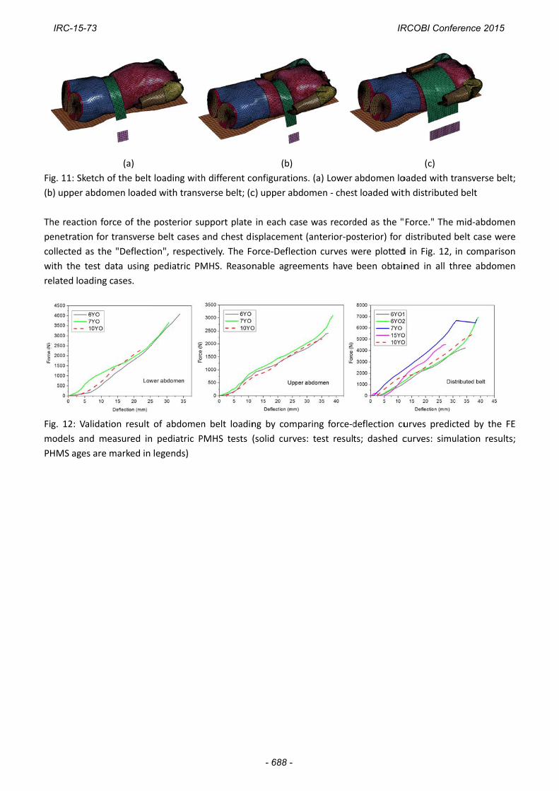
g. 11: Sketch
b) upper abd
he reaction f
enetration fo
ollected as t
with the test
elated loadin
g. 12: Valida
models and m
HMS ages ar
(a)
h of the belt
omen loade
force of the
or transverse
he "Deflecti
data using
ng cases.
ation result
measured in
re marked in
loading with
d with transv
posterior su
e belt cases
on", respect
pediatric PM
of abdomen
n pediatric P
legends)
h different co
verse belt; (c
upport plate
and chest di
tively. The Fo
MHS. Reason
n belt loadin
PMHS tests (
(b)
onfiguration
c) upper abd
in each cas
isplacement
orce‐Deflect
nable agree
ng by comp
(solid curves
s. (a) Lower
omen ‐ ches
e was record
(anterior‐po
ion curves w
ments have
aring force‐d
s: test result
abdomen lo
st loaded wit
ded as the "
osterior) for
were plotted
been obtain
deflection cu
ts; dashed c
(c)
oaded with t
th distributed
Force." The
distributed
d in Fig. 12,
ned in all th
urves predic
curves: simu
ransverse be
d belt
mid‐abdom
belt case we
in compariso
hree abdom
cted by the
ulation resul
elt;
en
ere
on
en
FE
ts;
IRC-15-73 IRCOBI Conference 2015
- 688 -