abstract - nasa · abstract: this essay outlines ... a supersonic aircraft which is expected to ......
TRANSCRIPT

Abstract:
This essay outlines the design for the V-3, a supersonic aircraft which is expected to
be a common mode of flying for civilian use by the year 2020. The V-3 will be able to
meet the following set of criteria when put into production:
Cruise speed: Mach 1.6
Range: 4,000 nautical miles (4,600 miles)
Effective payload: 40 passengers
Fuel efficiency: 3 passenger-miles per pound of fuel
Take-off field length: < 10,000 feet
In addition to the above characteristics, the V-3 will also be introduced as the most
efficient supersonic aircraft created, meeting all ecological standards and passing
noise emission tests, both at airports as well as during flight. The V-3 will address key
issues/problems facing present supersonic aircrafts such as sonic boom reduction,
propulsion and aerodynamic airframe efficiency. The V-3 is also expected to be able
to transport passengers from one place to another faster than any commercial aircraft
present in civil aviation today, without causing undue damage to the environment.
Furthermore, this project also proposes a civil aviation system to be formed by the
year 2020 which will pave the way for the V-3 and other supersonic aircrafts to
navigate the skies with as little interference to the communities below them as
possible.
Page | 2

1. Methodology:
This section will provide a brief overview of the methodology used in this project.
All references, materials and research used in this essay are obtained from textbooks
and websites on basic, advanced and supersonic aerodynamics. The author has cross-
referenced all research data for purposes of surety of information used. The project
will mainly use existing concepts of supersonic flight, along with self-generated ideas
which are yet to be tried or tested. However, these ideas are based on sound
aerodynamic and physical principles. The project and the aircraft design described
therein has not, to the best of the author’s knowledge, used patented ideas and any
reference to, or mention of, an intellectual patent has been checked to make sure it is
legal to reproduce it. This paper will follow a standard format for topical research
essays.
2. Introduction:
October 14, 1947. Airman Chuck Yeager created history and opened up a whole new
sky when he throttled the rocket-powered Bell X-1 beyond the speed of sound. The
day would surely come when civilians too could “break the sound barrier”. And so it
did. The Concorde revolutionized the way people view passenger transport by way of
an aircraft that could travel at over two times the speed of sound. However, on 26th
November, 2003, the Concorde officially retired from service and no other supersonic
passenger aircrafts remain today.
October 14, 2020. Enter the V-3. A hiatus of 17 years ends with the advent of a new
supersonic aircraft which can revolutionize civilian air transport. The V-3 will be
required not only to have unprecedented flight efficiency, but also to comply with
international standards of ecological safety and noise levels in order to provide
civilians with a safe, eco-friendly, economically viable mode of supersonic transport.
This essay describes, as accurately as possible, the design for the V-3.
3. THE V-3: Structure.
3.1 Aircraft Design and structure:
The V-3 has a unique fuselage-and-wing configuration. The main
structure follows from NASA’s N-plus-21 idea for a silent, non-carbon-emitting
aircraft. The wings of the aircraft are extremely large in comparison to normal ‘tube-
and-wing’ designs seen in most passenger aircrafts today. The fuselage, however, is
made much smaller because of lower payload requirements and this makes the wings
the most significant component of the aircraft which is in contrast to most present day
fuselage-centered models. This leads to an aircraft shape as shown in Fig. 1. The V-3
incorporates forward-swept wings in its design. The basic shape of the V-3 is an
isosceles triangle with the nose of the aircraft flush in line with the tips of the wings.
The reason for such a design is the increased stability at speeds at and beyond critical
Mach. This will be explained further in Section 3.2.
N-plus-2 is the second stage in NASA’s project to create a silent carbonless airplane by the year
2020.
Page | 3
1

Fig. 1
One of the main requirements for a supersonic transport (SST) is that it
must have as little rate of change in CSA as possible. According to the Whitcomb
Area Rule, any discontinuities in the total cross-sectional area (CSA) of a body (and
not necessarily the CSA of the fuselage) will increase the body’s wave drag during
transonic flight because shock waves are formed at these points. Therefore the perfect
shape for any aircraft traveling at a transonic speed must follow an aerodynamically
shaped cross-sectional frame called the Sears-Haack shape (The Sears-Haack body
has the least rate of change of CSA in comparison to other shapes). However, the V-
3’s shape will follow a rear-skewed Sears-Haack shape because for supersonic
aircrafts, the CSA must be the same along the line of the Mach wave lines2 and not
along the line perpendicular to airflow (parallel to wingspan). The V-3 is designed
such that it’s CSA exactly conforms to the Sears-Haack body for a supersonic aircraft
of its cruise speed (Mach 1.6). This is done so that there is minimal wave drag
experienced during flight.
The skin of the fuselage and wings of the V-3 are made not solely with an alloy of
metals, but with CFRP3-reinforced duralumin. CFRP is light, highly tensile, has a
very high modulus of elasticity and low thermal expansion capacity. It is also
chemically inert. This makes it ideal as a material for fuselage since it can be used to
build a light body and does not expand easily at supersonic speeds when skin friction
leads to temperatures of about 100 degrees centigrade. However, CFRP has a major
disadvantage. It is extremely brittle. In order to overcome this, it is mixed with
duralumin. The duralumin forms a matrix for the CFRP chains and these chains are
2 Mach Wave lines are the representative lines of the shock waves formed at supersonic speeds.
3 Carbon Fiber-Reinforced Polymer is a material commonly used in airplane and helicopter bodies.
Page | 4
effectively embedded in the metal alloy. Duralumin is very sturdy and has a high
melting point. It is not brittle and when reinforced with CFRP, can form a material
that can safely be used for the aircraft wings, fuselage, and control surfaces. Because
of its high tensile strength, the CFRP-reinforced Duralumin makes the final airplane
skin material difficult to break, stretch or tear. During normal flight, the aircraft
encounters several stray shards of particulate matter in the air which are potentially
dangerous at such high speeds as Mach 1.6. The CFRP-Duralumin body is expected
to be resistant to such impacts allowing for a safe flight.
The spike at the nose of the aircraft is extended only at supersonic speeds and remains
extended until final descent and landing4. At super-cruise, the maximum extension of
the spike is almost two-fifths of the total fuselage length. One of the most important
aspects of the V-3’s mainframe is it’s wing surfaces. The wings provide optimum lift
conditions both during subsonic and during supersonic flight (Section 3.2). The
aircraft has no independent horizontal stabilizer but the operative horizontal
stabilizers are placed at the base of the wings. Horizontal stabilizers are not used
because if they are placed at the rear, the wings will have to be shifted forward to
accommodate them which will change the isosceles triangle shape of the aircraft. At
supersonic speeds, a canard wing system is difficult to use because smooth laminar
flow is disrupted at the first wing surface which causes disturbances at the main wing.
The vertical stabilizer, however, is placed at the rear end of the aircraft.
3.2 Wings:
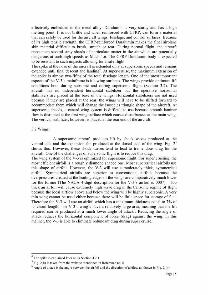
A supersonic aircraft produces lift by shock waves produced at the
ventral side and the expansion fan produced at the dorsal side of the wing. Fig. 25
shows this. However, these shock waves tend to lead to tremendous drag for the
aircraft. One of the challenges of supersonic flight is to reduce this drag.
The wing system of the V-3 is optimized for supersonic flight. For super cruising, the
most efficient airfoil is a roughly diamond shaped one. Most supercritical airfoils use
this shape of airfoil. However, the V-3 will use a moderately thick, symmetrical
airfoil. Symmetrical airfoils are superior to conventional airfoils because the
overpressures created at the leading edges of the wings are comparatively much lower
for the former (The NACA 4-digit description for the V-3’s airfoil is 0007). Too
thick an airfoil will cause extremely high wave drag in the transonic regime of flight
because the local airflow above and below the wing will be highly supersonic. A very
thin wing cannot be used either because there will be little space for storage of fuel.
Therefore the V-3 will use an airfoil which has a maximum thickness equal to 7% of
its chord length. The V-3’s wing’s have a relatively large area, meaning that the lift
required can be produced at a much lower angle of attack6. Reducing the angle of
attack reduces the horizontal component of force (drag) against the wing. In this
manner, the V-3 is able to eliminate redundant drag during super cruise.
4 The spike is explained later on in Section 4.2.1
5 Fig. 2(b) is taken from the website mentioned in Reference no. 8
6 Angle of attack is the angle between the airfoil and the direction of airflow as shown in Fig. 2 (b)
Page | 5
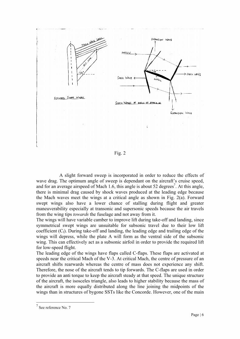
Fig. 2
A slight forward sweep is incorporated in order to reduce the effects of
wave drag. The optimum angle of sweep is dependant on the aircraft’s cruise speed,
and for an average airspeed of Mach 1.6, this angle is about 52 degrees7. At this angle,
there is minimal drag caused by shock waves produced at the leading edge because
the Mach waves meet the wings at a critical angle as shown in Fig. 2(a). Forward
swept wings also have a lower chance of stalling during flight and greater
maneuverability especially at transonic and supersonic speeds because the air travels
from the wing tips towards the fuselage and not away from it.
The wings will have variable camber to improve lift during take-off and landing, since
symmetrical swept wings are unsuitable for subsonic travel due to their low lift
coefficient (Cl). During take-off and landing, the leading edge and trailing edge of the
wings will depress, while the plate A will form as the ventral side of the subsonic
wing. This can effectively act as a subsonic airfoil in order to provide the required lift
for low-speed flight.
The leading edge of the wings have flaps called C-flaps. These flaps are activated at
speeds near the critical Mach of the V-3. At critical Mach, the centre of pressure of an
aircraft shifts rearwards whereas the centre of mass does not experience any shift.
Therefore, the nose of the aircraft tends to tip forwards. The C-flaps are used in order
to provide an anti torque to keep the aircraft steady at that speed. The unique structure
of the aircraft, the isosceles triangle, also leads to higher stability because the mass of
the aircraft is more equally distributed along the line joining the midpoints of the
wings than in structures of bygone SSTs like the Concorde. However, one of the main
See reference No. 7
Page | 6
7

problems associated with using the C-flaps is that it leads to tremendous drag for an
aircraft during transonic flight in the form of wave drag. Therefore, a secondary
measure is necessary to ensure that the tendency for tipping of the nose is brought to a
bare minimum. The fuel in the wings moves towards the base of the wings so that the
centre of mass also shifts rearwards. This makes the required angle of incidence of the
C-flaps much lower, leading to lesser wave drag.
Fig. 3
3.3 Engines:
The V-3 will not use engines previously used for supersonic aircrafts like the
Concorde and the Tupolev series. The use of Variable Cycle Engines (VCEs) will be
relevant by the year 2020 and they have been proved to be the most efficient engines
for mixed range flights. The V-3 will employ the use of a type of VCE known as the
Tandem Fan Engine (Fig. 4). The tandem fan engine can work at a much lesser noise
level than turbojets and even some high-bypass turbofans. They are efficient during
all speed ranges of the V-3. During supersonic flight, the air flows through the
primary fan and straight through to the second fan. However, at subsonic speeds, most
of the jet flow from the first fan is allowed to bypass the rear fan and is released
through a separate outlet. An auxiliary inlet T is used to allow air to flow in to the rear
fan and exhaust gases are let out directly through the main nozzle N. This reduces the
jet velocity, keeping the specific thrust constant, and therefore its noise emission at
airports is greatly diminished.
Page | 7

The main engines are shown in figure 4 below. Most jet engines cannot
take in air flow greater than Mach 0.6. This is because shock waves are produced at
and around the walls of the engines. For the V-3, however, at subsonic speeds, the air
flows into the engines directly, but at supersonic speeds, adjustable engine caps are
moved into place. These caps allow the little air flowing in through the aperture to
expand isentropically until the entry point of the first fan, and the air intake velocity is
effectively reduced from the cruise speed of Mach 1.6 to the required Mach 0.5. The
ratio of the diameter of the aperture to the point of inlet into the engine can be
calculated8 by using a simplified form of Bernoulli‘s equation for fluid dynamics and
Pascal‘s Law for fluids:
Fig. 4
Bernoulli’s equation:
P2 + � (dV22) = P1 + � (dV1
2 )
Pascal’s Law for fluids: P1 x A2 = P2 x A1
Where P1 and P2 are pressures of the gas at point 1 and 2,
d is the density of the inflow air,
A1 and A2 are the CSAs at the points 1 and 2.
And V1 and V2 are the velocities at points 1 and 2.
The calculation involves solving for two ratios, given two equations. For sake of brevity, the actual
calculation is not shown here.
Page | 8
8
V1 and V2 are Mach 1.6 and Mach .5 (in m/s) respectively
Exact values for P1 and P2 can be extracted from actual experiments in wind tunnels
during the Research & Development stage of the aircraft.
3.4 Control Systems:
The V-3 is a Control Configured Vehicle which uses optical fibers to transmit signals
from the cockpit to the control surfaces. Fly-by-Optics systems are used mainly
because extremely precise measurements of aerodynamic forces and torques are
necessary at supersonic speeds. Human reaction time is too high when compared to
reaction times required for control during transonic and flight where airflow and
shock wave formation is unpredictable. Fly-by-Optics is a new system of aircraft
control in which optical fibers are used to transmit signals from the cockpit to the
control surfaces. The negative aspect of a Fly-by-Optics system is the added weight of
a computer to manage and network between the control surfaces. This will lead to fuel
inefficiency, but the advantage of using a computerized control system supersedes the
disadvantage of the increased weight in terms of superior flight performance and
safety. Fly-by-Optics systems are advantageous over conventional Fly-by-Wire
systems because electromagnetic waves from external sources do not affect the flight
control signals.
The wing control surfaces of the V-3 are placed at the positions shown in Fig. 3. The
ailerons are placed at one-third and two-thirds distance of the total wingspan and the
C-flaps are shown on the underside of the wings. The vertical stabilizer has a full
length rudder for better yawing ability.
During the transition from the subsonic regime to supersonic, the C-flaps will
activate, allowing for a lift of the leading side of the aircraft. At transonic speeds, the
powerful wave drag must also be overcome. In order to do this, the engines of the V-3
use afterburners during transonic speeds of about Mach .9 to .95 to push through the
wave drag and into supersonic flight.
4. Airport Noise Control and Sonic Boom Reduction.
4.1 Airport Noise Control:
The main reason for a jet engine producing high levels of noise is that the
flow of exhaust gases is turbulent. If the jet flow can be made laminar, it would
considerably reduce noise emissions. Reynolds’ number determines the characteristics
of the fluid flow and it is given by:
Re = 2dVR/k
where d is density of fluid, V is fluid velocity, R is radius of nozzle, and k is dynamic
viscosity of fluid.
In order to promote laminar flow, Reynolds’ number must be low, and
therefore, assuming ceteris paribus, k or dynamic viscosity must be increased. One
method to increase viscosity of the exhaust fumes (mainly composed of CO2) is by
dissolving long chain carbon polymers in it. Therefore, at the exhaust nozzle, a
continuous flow of liquid emulsions will be dissolved with the exhaust fumes and will
exit the VCE. One example of a viable emulsion is polypropylene. It is an
Page | 9

ecologically harmless polymer and can be dissolved9, along with a co-solvent, in
gaseous CO2. However, polypropylene is a solid at room temperature and therefore, it
must be liquefied in order to be useful as a solvent. The excess heat from the engine
can be removed using a coolant and this heat can be controlled and used to liquefy the
polypropylene. This can be done without breaking the chain since the melting point
of polypropylene is about 160 degrees centigrade whereas the decomposition
temperature is 300 degrees centigrade.
4.2 Sonic Boom Reduction:
Sonic Boom reduction measures must be treated in an integrated manner.
The two parameters of boom reduction are the aircraft and the community it affects.
Hence, there are two ways of reducing the effect of sonic booms.
4.2.1 Boom reduction measures in aircraft:
Sonic Boom intensity is directly proportional to the acceleration of the air
particles due to supersonic airflow around an aircraft. The fuselage and the wings of
the V-3 are designed specially to decrease boom intensity. When the aircraft breaks
the sound barrier, a spike extends from the nose of the aircraft. The spike will extend
in front of the base of the isosceles triangle shape of the aircraft and therefore, this is
the point at which the sonic boom forms. The spike initiates the sonic boom more
gradually than the nose of the aircraft and also helps to “spread out” the sonic boom
over a greater length of aircraft which together help reduce boom intensity
considerably. The wings have a very thin leading edge; this means that, like the spike,
it can initiate the sonic boom in a much more gradual manner, leading to lower boom
intensity.
4.2.2 Boom reduction measures in community:
The success of the project to introduce supersonic travel as a viable mode
of travel in the future is as dependent on aircraft manufacturing companies as the
countries wishing to see it happen. Therefore, it is proposed that by the year 2020, a
system be effected that consists of receivers-cum-transmitters placed on the surface of
the Earth which can detect the characteristics of the sonic boom, and transmit sound
waves which will cancel out the noise from the boom by using destructive
interference of the shock wave. Even though the sonic boom does not have normal
physical characteristics of a mechanical wave, it still has a frequency and amplitude.
The boom reduction system can exploit these characteristics of the sonic boom,
thereby reducing or completely eliminating its effect. This system works much like
the modern day noise cancelling earphones which use Active Noise Control (ANC).
Such a system, however, is not limited to sonic booms. It will be capable of
eliminating or (lowering the volume of) all noises above a certain PLdB10
which can
be an added advantage to communities in the future.
9 A good solvent for polypropylene is yet to be discovered, owing to its insolubility in most organic
solvent. However, Tetrachloromethane can dissolve polypropylene to a sufficient degree. 10
PLdB is a measure of perceived loudness as compared to decibels which measures noise intensity.
PLdB takes into account loudness perceived indoors, outdoors and under varying climatic conditions.
This makes it a better metric of sonic boom intensity than the decibel.
Page | 10

5. Flight characteristics:
The V-3 is designed for subsonic, transonic and supersonic flight. During subsonic
flight, (mainly take-off, climbout and landing) the V-3 sports a subsonic wing.
Consequently, at these speeds, the V-3 uses equations for lift according to subsonic
airfoils. The subsonic wing is shifted to a supersonic one during the transonic flight
with the help of the variable camber wing (shown in the figure below).
A regular wide body passenger jet has a take off field length requirement of 8,000 to
13,000 feet. The V-3 requires much less runway length because the large wing area in
relation to the size of the fuselage produces much higher overall lift than those of
conventional aircrafts. The V-3 is also lighter in terms of mainframe weight, and
therefore, can also take off with much less lifting force. This lifting force, therefore,
can be produced with less runway length. The V-3 has high aerodynamic efficiency,
leading to lower form drag and parasitic drag.
The V-3 is expected to carry about 40 passengers for a distance of roughly 4600
miles. At 3 passenger-miles per pound of fuel, that equates to about 61,350 pounds of
fuel. This fuel can be stored in the wings of the aircraft and at rear end of the base of
the fuselage.
The V-3, being a supersonic aircraft, must encounter as little form drag as possible
during flight. Assuming that the wetted surface area is kept constant, the only other
parameter that can be changed is the altitude at which the aircraft flies. The higher the
aircraft flies, the lower is the drag associated with it’s motion through that particular
airframe. Another advantage of flying at a higher altitude is that the intensity of sonic
booms decreases with increasing altitude. However, the V-3 cannot fly at too high an
altitude because of passenger safety concerns like cosmic ray radiation and prolonged
exposure to high levels of ultra-violet ray radiation. Also, the oxygen levels start
Page | 11

decreasing with increasing altitude. In the absence of oxygen, the CFRP chains can be
decomposed thermally. In order to maintain safety standards, the optimum altitude for
the V-3 is about 50,000 feet above sea level. Most supersonic aircrafts travel at a
higher altitude but the V-3’s low parasitic drag allows it to work efficiently even at as
low an altitude as 50,000 feet.
6. Flying the V-3 in 2020:
If the V-3 is to be used a viable mode of supersonic transport by the year 2020,
changes must be effected in the aviation infrastructure of all countries involved in the
project. The primary reason for this is that sonic booms created by supersonic aircrafts
may cause noise pollution in all geographical lands which are swept under the boom
carpet. The use of ANC systems to cancel oncoming sonic booms will be a necessary
measure for all these landforms because of the need to comply with international
regulations on noise emissions.
Another modification in infrastructure required to integrate the V-3 into civil aviation
is that airports must be able to house and manage the aircraft. This will mean that
airports must widen their runways, have ground support crew to help the V-3 taxi off
the runway (the engine of the V-3 is highly inefficient on the runway during
positioning and taxiing, much like the Concorde) and locate runways further away
from main terminals for minimum disturbance at the airports.
The V-3, with its expensive in-flight equipment, sophisticated technology
and seemingly redundant environment-friendly measures will prove much more
expensive to the common man than regular jet air travel. This may raise concerns
about the economic viability of such supersonic air travel. However, the primary aims
of the V-3 are to provide a safe, comfortable, ecologically stable method of flying at
supersonic speeds in the near future. Undoubtedly, traveling supersonic will be more
expensive, but the V-3 aims to reduce passenger expense without compromising on
primary aspects such as flight safety, and environment-friendliness. The high fuel
efficiency of the V-3 will mean that the per capita cost for this sector is much lower.
Another segment where the V-3 will be able to cut costs is in travel comfort. Most
present-day airliners have high overhead charges because of luxury interior designs
and extra comfort features for passengers. The V-3 will reduce costs here as it is
designed to provide a balance between passenger comfort and cost. The maximum
time of flight for the V-3 is about 4 hours and therefore, passengers will be able to
reach their destination in a manageable period of time.
7. Future Avenues:
The V-3 has been conceptualized and designed in the year 2009. Technological
advancements, however, take place every year and the advent of these new
technologies can certainly be incorporated into the design of the V-3 insofar as it does
not clash with its performance and ecological goals. The concept of variable cycle
engine is still new and there is great potential for expansion in this field of propulsion.
NASA’s Supersonics Project continually aims to improve practical designs for
supersonic flight models through various avenues of research such as Sonic Boom
Modeling and Multidisciplinary Design, Analysis and Optimization. This and other
projects will undoubtedly contribute to the design of the V-3 in years to come. The V-
3 project team will be required to conduct many further hours of testing, research and
experiments in order to make this idea a reality.
Page | 12

8. Conclusion:
Keeping the primary concerns of safety, environment friendliness and flight
efficiency in mind, the V-3 is designed in order to be a viable mode of transport by
the year 2020. It’s ability to provide supersonic air travel open to passengers without
damaging the environment will make it a good example of sustainable development,
one of the thrust areas of world progress today. It is hoped that by the year 2020, all
countries concerned with the project to make sustainable supersonic flight a reality
can agree to a universal standard in terms of flight parameters like noise and emission
levels. If the official retirement of the Concorde was a step backward in aviation
history, then the arrival of the V-3 will be a bigger step forward; a step that man can
look back upon as the beginning of a new era in aviation history.
Page | 13
9. References:
1) Ilan Kroo. “Applied Aerodynamics: A Digital Textbook”. Desktop Aeronautics,
Inc. January 2007.
<http://www.desktopaero.com/appliedaero/preface/welcome.html>
2) Peter Coen, Mary Jo Long-Davis, and Dr. Louis Povinelli. “Fundamental
Aeronautics Program, Supersonics Project, Reference Document”. National
Aeronautics and Space Administration. 26 May, 2006.
<http://www.aeronautics.nasa.gov/nra_pdf/sup_proposal_c1.pdf>
3) Carlo Kopp. “Artificial Stability and Fly-by-Wire Control”. Australian Aviation
and Defence Review. 2005. <http://www.ausairpower.net/AADR-FBW-CCV.html>
4) Deborah Bazar. “The work of wings”. Virtual Skies interactive tutorial.
<http://virtualskies.arc.nasa.gov/vsmenu/vsmenu.html>
5) Don Baals, Warner Robins and Roy Harris, “Aerodynamic Design Integration of
Supersonic Aircraft”, Journal of Aircraft, Vol. 7, No. 5, pp. 385-394
6) (Anonymous) “Chemical Fact Sheet: Polypropylene”. Orica Limited. October
1992. <http://www.pacia.org.au/_uploaditems/docs/3.polypropylene.pdf>
7) Carl Knowlen. “High Speed Flight”. Department of Aeronautics and Astronautics,
<http://www.aa.washington.edu/courses/aa101/Lectures/aa101_19-highspeed.pdf>
8) (Anonymous) “How do Lift and Drag Work at Supersonic Speeds?” Website of the
Smithsonian National Air and Space Museum. February, 1999.
<http://www.nasm.si.edu/exhibitions/GAL109/NEWHTF/HTF525.HTM>
9) Ilan Kroo. “Propulsion Systems: Basic Concepts”. Aircraft Aerodynamics and
Design Group, Stanford University. January, 1999.
<http://www.nasm.si.edu/exhibitions/GAL109/NEWHTF/HTF525.HTM>
10) Dr. Robert M. Enick. “A Literature Review of Attempts to Increase the Viscosity
of Dense Carbon Dioxide”. Website of the National Energy Technology Laboratory.
October, 1998. <http://www.netl.doe.gov/publications/others/techrpts/co2thick.pdf>
11) Dmitri Kopeliovich. “Carbon Fiber Reinforced Polymer Composites”. Substech.
September, 2008.
<http://www.substech.com/dokuwiki/doku.php?id=carbon_fiber_reinforced_polymer
_composites>
12) “Theories of Flight (Aerodynamics)”. U.S. Centennial of Flight Commission.
<http://www.centennialofflight.gov/essay_cat/9.htm>
13) Jeff Scott. “Area Rule and Transonic Flight”. Aerospaceweb.org. November,
2002. <http://www.aerospaceweb.org/question/aerodynamics/q0104.shtml>
14) Jennings Heilig. “What’s the angle?”. March, 2003.
Page | 14

15) (Anonymous) “Concorde-Jet”. TREBOSC. 2006. <http://www.concorde-
jet.com/e_vols.htm>*
16) (Anonymous) “The Problem”. Undated.
<http://www.cebuanderson.com/problem.htm>
17) Jim Hodges. “The Quest: A Silent, Carbonless Airplane”. NASA Langley
Research Centre. February, 2009.
<http://www.nasa.gov/centers/langley/news/researchernews/rn_colliergreenbag.html>
*Clarifications: The author confirms that he can read and understand French. The
webmaster warns against reproduction of material from the site. In this essay,
however, no part of the website is reproduced, and merely technical data from the
website is gathered. This is in accordance with French law regarding Information
Technology and Freedom.
Page | 15