abstract title: cyber-security risk assessment …
TRANSCRIPT

ABSTRACT
Title: CYBER-SECURITY RISK ASSESSMENT
Susmit Azad Panjwani, Doctor of Philosophy, 2011
Dissertation directed by: Professor Gregory B. Baecher, Department of Civil and Environmental Engineering
Cyber-security domain is inherently dynamic. Not only does system configuration
changes frequently (with new releases and patches), but also new attacks and
vulnerabilities are regularly discovered. The threat in cyber-security is human, and hence
intelligent in nature. The attacker adapts to the situation, target environment, and
countermeasures. Attack actions are also driven by attacker’s exploratory nature, thought
process, motivation, strategy, and preferences. Current security risk assessment is driven
by cyber-security expert’s theories about this attacker behavior.
The goal of this dissertation is to automatically generate the cyber-security risk
scenarios by:
Capturing diverse and dispersed cyber-security knowledge
Assuming that there are unknowns in the cyber-security domain, and new
knowledge is available frequently

Emulating the attacker’s exploratory nature, thought process, motivation,
strategy, preferences and his/her interaction with the target environment
Using the cyber-security expert’s theories about attacker behavior
The proposed framework is designed by using the unique cyber-security domain
requirements identified in this dissertation and by overcoming the limitations of current
risk scenario generation frameworks.
The proposed framework automates the risk scenario generation by using the
knowledge as it becomes available (or changes). It supports observing, encoding,
validating, and calibrating cyber-security expert’s theories. It can also be used for
assisting the red-teaming process.
The proposed framework generates ranked attack trees and encodes the attacker
behavior theories. This information can be used for prioritizing vulnerability remediation.
The proposed framework is currently being extended for developing an automated threat
response framework that can be used for analyzing and recommending countermeasures.
This framework contains behavior driven countermeasures that uses the attacker behavior
theories to lead the attacker away from the system to be protected.

CYBER-SECURITY RISK ASSESSMENT
by
Susmit Azad Panjwani
Dissertation submitted to the Faculty of the Graduate School of the University of Maryland, College Park, in partial fulfillment
of the requirements for the degree of Doctor of philosophy
2011
Advisory Committee:
Professor Gregory B. Baecher, Chair Professor Ali Mosleh Professor Miroslaw J. Skibniewski Professor Barney Corwin Professor John Cable

© Copyright by
Susmit Azad Panjwani
2011

ii
Dedication
To my family - Asha, Azad, Snehal and Sonal.

iii
Acknowledgements
I owe my deepest gratitude to my adviser, Dr. Gregory B. Baecher, for his excellent
guidance, support, encouragement, and patience over the years. I truly appreciate him
helping me continuously improve the quality of my work.
It would have been next to impossible to write this dissertation without the help and
guidance of Dr. Ali Mosleh. I owe my sincere and earnest thankfulness for all his support
and suggestions for my research.
I am truly indebted and thankful to Ernest Soffronoff for keeping me on the track,
providing insightful practical knowledge, and for being my sounding board time after
time.
I would like to show my gratitude to Dr. Barney Corwin for providing his valuable
management insight for my research. I would also like to thank Professor Miroslaw
Skibniewski, Professor Jimmie West, and Professor John Cable for their guidance over
the years.
I am truly grateful to all my committee members for their time and support. I would
also like to thank Craig Morris for the intellectual discussions over the years.
I would like to thank Marta Augustyn and Misia for their support and affection.
Finally, and most importantly, I would like to thank my family, Asha, Azad, Snehal and
Sonal. Their encouragement and unwavering love have always been my source of
strength.

iv
Table of Contents Dedication .................................................................................................................... ii
Acknowledgements .................................................................................................... iii
1 Introduction ..................................................................................................... 1
2 Characterization of the Security Domain ........................................................ 4
2.1 Introduction ..................................................................................................... 4
2.2 State of Security .............................................................................................. 4
2.3 State of Cyber-security Risk Assessment and Risk-based Decision .............. 7
2.4 Security Domain Characteristics and Impact on Risk Assessment ................ 9
2.4.1 Expert Theories ..................................................................................... 10
2.4.2 Domain Dynamicity .............................................................................. 10
2.4.3 Intelligent Threat ................................................................................... 11
3 Requirements of Risk Assessment Methodology ......................................... 13
3.1 Introduction ................................................................................................... 13
3.2 Risk Assessment Process of Different Domains ........................................... 13
3.2.1 Engineering System Risk Assessment .................................................. 14
3.2.2 Environmental risk assessment ............................................................. 22
3.2.3 Infrastructure Security Risk Assessment .............................................. 28
3.2.4 Cyber-security risk assessment ............................................................. 31
3.3 Domain Characteristic Comparison and Limitation of Cyber-security Risk Assessment .................................................................................................................... 41
3.3.1 Engineering System Domain and Risk Assessment Method ................ 43
3.3.2 Environmental Risk Assessment........................................................... 44
3.3.3 Infrastructure Security Domain and Risk Assessment Method ............ 44
3.3.4 Cyber-security Domain and Risk Assessment Method ........................ 45
3.4 Detailed Cyber-Security Domain Requirements .......................................... 47
3.4.1 Domain Dynamicity .............................................................................. 47
3.4.2 Attacker Behavior ................................................................................. 50
3.4.3 Expert Theory ....................................................................................... 51
3.4.4 Automation ........................................................................................... 52
3.5 Risk Scenario Generation ............................................................................. 52
3.5.1 Current Focus of Risk Scenarios ........................................................... 52
3.5.2 Current Methods for Generating Cyber-security Risk Scenario ........... 54
v
3.5.3 Proposed Cyber-security Risk Scenario Generation Framework ......... 64
4 Proposed Framework .................................................................................... 69
4.1 Conceptual Planning Framework .................................................................. 69
4.1.1 Goals ..................................................................................................... 71
4.1.2 System Model ....................................................................................... 72
4.1.3 Action Model ........................................................................................ 73
4.1.4 Planning Philosophy ............................................................................. 74
4.1.5 Planning Framework Classification ...................................................... 75
4.1.6 Knowledge ............................................................................................ 77
4.1.7 Dynamicity ............................................................................................ 78
4.1.8 Application of Planning for Critical Domain ........................................ 79
4.2 Comparison of Planning Architectures ......................................................... 80
4.3 Proposed Planning Framework ..................................................................... 88
4.3.1 Goals ..................................................................................................... 88
4.3.2 Planning Philosophy ............................................................................. 90
4.3.3 Knowledge Representation ................................................................... 92
4.3.4 System Model and Action Model ....................................................... 101
4.3.5 Dynamicity .......................................................................................... 102
4.3.6 Planning Algorithm ............................................................................. 107
4.3.7 Planning Output .................................................................................. 123
5 Framework Architecture ............................................................................. 127
5.1 Flux ............................................................................................................. 127
5.2 CieKI ........................................................................................................... 127
5.3 Modes of Operation .................................................................................... 128
5.4 Case Study .................................................................................................. 129
6 Framework Component: Flux ..................................................................... 132
6.1 Flux: Overview ........................................................................................... 132
6.1.1 Capture Diverse and Dispersed Cyber-security Domain Knowledge . 132
6.1.2 Incomplete Information ...................................................................... 135
6.1.3 Distributed Planning Logic ................................................................. 135
6.1.4 Contextual Interpretation .................................................................... 135
6.1.5 Information Validation ........................................................................ 136
6.2 Ontology Logic Representation .................................................................. 136
6.3 Asset Ontology............................................................................................ 137

vi
6.3.1 Specific Asset Information ................................................................. 137
6.3.2 Abstract Asset Information ................................................................. 141
6.3.3 Information Integration ....................................................................... 146
6.4 Threat Ontology .......................................................................................... 150
6.4.1 Source of Information ......................................................................... 150
6.4.2 Threat Ontology Logic ........................................................................ 153
6.5 Planning Ontology ...................................................................................... 160
6.5.1 Introduction ......................................................................................... 160
6.5.2 Planning Ontology: Anchor and Catcher Sets .................................... 161
6.5.3 Planning Ontology: Functional Description ....................................... 163
7 Framework Component: CieKI .................................................................. 178
7.1 Situational Dynamic Decision Tree ............................................................ 178
7.2 Attacker Behavior Ontology ....................................................................... 182
7.2.1 Encoding Attacker Strategy ................................................................ 184
7.3 Centralized Algorithms ............................................................................... 189
8 Framework Modes of operation .................................................................. 190
8.1.1 Attack Tree Generation without Attacker Preference ......................... 191
8.1.2 Attack Scenario Generation Using Red-team ..................................... 197
8.1.3 Attack Scenario Generation Using Encoded Attacker Behavior Theory 212
8.1.4 Attack Tree Generation Using Attacker Behavior .............................. 215
8.1.5 Direct Query ........................................................................................ 216
9 Framework Evaluation and Comparison .................................................... 219
9.1 Cyber-security Domain Requirements Comparison ................................... 219
9.1.1 Domain Dynamicity ............................................................................ 219
9.1.2 Attacker Behavior ............................................................................... 221
9.1.3 Expert Theory ..................................................................................... 222
9.1.4 Automation ......................................................................................... 222
9.2 Case Study Comparison .............................................................................. 226
9.2.1 Comparison of Input ........................................................................... 227
9.2.2 Comparison of Output......................................................................... 238
10 Research Contribution, Application and Extension ................................ 249
10.1 Research Contributions ........................................................................... 249
10.1.1 Generating Risk Scenarios by Incorporating the Cyber-security Domain Requirements ............................................................................................. 249

vii
10.1.2 Assisting the Red Teaming Process ................................................ 251
10.1.3 Simplifying Risk Scenarios Generation, and Increasing Traceability and Reuse 252
10.1.4 Identifying the Cyber-security Domain Characteristics ................. 254
10.1.5 Providing the Core Framework to Enable Potential Defensive and Expert Validation Applications ............................................................................... 254
10.2 Applications and Extensions ................................................................... 255
10.2.1 Cyber-security Risk Assessment ..................................................... 255
10.2.2 Countermeasure Development ........................................................ 260
10.2.3 Security Expert Theory Validation ................................................. 263
10.2.4 Attack Data Collection .................................................................... 276
10.2.5 Unifying Security Assessment Efforts ............................................ 277
11 Conclusion .............................................................................................. 280
Appendix I: Attacker Behavior ................................................................................ 284
Appendix II: Ontology ............................................................................................. 286
Appendix III: Technologies used in this dissertation .............................................. 292
Appendix IV: Annualized Loss Expectancy ........................................................... 293
Appendix V: Output of proposed framework .......................................................... 294
Appendix VI: Cognitive Security Metrics ............................................................... 296
Appendix VII: Automated Event Sequence Diagram Generation ........................... 299
Glossary ................................................................................................................... 301
References ............................................................................................................... 306

viii
FIGURE 1: NUMBER OF REPORTED VULNERABILITIES IN LAST DECADE- SOURCE OF DATA [5] .......................... 5 FIGURE 2: COMPARISON OF NUMBER OF VULNERABILITIES REPORTED IN 2010 WITH TOTAL NUMBER OF
VULNERABILITIES REPORTED IN PAST DECADE - SOURCE OF DATA [5] .................................................... 6 FIGURE 3 STATE OF CYBER-SECURITY 2011 - SOURCE OF DATA [9] ................................................................ 7 FIGURE 4: RISK ASSESSMENT DOMAIN COMPARISION ..................................................................................... 43 FIGURE 5: ATTACK TREE - GRAPHICAL EXAMPLE ........................................................................................... 56 FIGURE 6 CONCEPUAL PLANNING FRAMEWORK ............................................................................................. 70 FIGURE 7: CONCEPTUAL FRAMEWORK FACTORS ............................................................................................ 71 FIGURE 8: COMPARISION OF PLANNING FRAMEWORKS ................................................................................... 80 FIGURE 9: EXAMPLE INDIVIDUALS ................................................................................................................ 93 FIGURE 10: EXAMPLE PROPERTIES ................................................................................................................. 94 FIGURE 11: PROPERTY CHAIN EXAMPLE ......................................................................................................... 94 FIGURE 12: EXAMPLE OF CLASS .................................................................................................................... 95 FIGURE 13: EXAMPLE OF CLASS ENCODING USING SPECIAL ‘TYPE’ PROPERTY ............................................... 95 FIGURE 14: EXAMPLE CLASS HIERARCHY ....................................................................................................... 96 FIGURE 15: EXAMPLE PROPERTY RESTRICTION .............................................................................................. 97 FIGURE 16: EXAMPLE OF CLASS HIERARCHY AND PROPERTY RESTRICTION ................................................... 97 FIGURE 17: EXAMPLE OF DIVERSE TYPES OF KNOWLEDGE ............................................................................. 99 FIGURE 18: OPEN WORLD PRE-REQUISITES .................................................................................................. 105 FIGURE 19: INTERACTION BETWEEN CETRALIZED AND DISTRIBUTED LOGIC ................................................ 109 FIGURE 20: GENERIC FLOW OF CENTRALIZED PLANNING ALGORITHMS ........................................................ 112 FIGURE 21 ANCHOR SET CLASSES ................................................................................................................ 115 FIGURE 22: ASSET ONTOLOGY EXAMPLE ...................................................................................................... 118 FIGURE 23 ASSET ONTOLOGY EXAMPLE ENCODING ABSTRACT INFORMATION ............................................. 119 FIGURE 24: PLANNING ONTOLOGY EXAMPLES - ANCHOR AND CATCHER CLASSES ....................................... 121 FIGURE 25: COMBINED LOGIC OF EXAMPLES ................................................................................................ 121 FIGURE 26 PROPOSED FRAMEWORK ARCHITECTURE WITH OUTPUT .............................................................. 128 FIGURE 27: CASE STUDY ARCHITECTURE .................................................................................................... 129 FIGURE 28: EXAMPLE FRAGMENT OF SPECIFIC INFORMATION ENCODING IN ASSET ONTOLOGY .................... 138 FIGURE 29: ASSET ONTOLOGY- INVERSE PROPERTIES ................................................................................. 139 FIGURE 30 EXAMPLE FRAGMENT SHOWING INVERSE RELATIONS ................................................................. 140 FIGURE 31: ASSET ONTOLOGY- INFORMATION ADDITION ........................................................................ 141 FIGURE 32 EXAMPLE OF SPECIFIC AND ABSTRACT INFORMATION ENCODING IN ASSET ONTOLOGY ............. 142 FIGURE 33 HIERARCHY OF PROPERTY RELATIONS ........................................................................................ 144 FIGURE 34 INFERENCES DRAWN FROM HIERARCHY OF PROPERTY RELATIONS.............................................. 145 FIGURE 35: ASSET ONTOLOGY- FUSION EXAMPLE ....................................................................................... 149 FIGURE 36: MINIMAL ENCODING OF PATTERN INFORMATION ....................................................................... 154 FIGURE 37: DETAILED ENCODING OF PATTERN INFORMATION ...................................................................... 155 FIGURE 38: TARGET OF THE PATTERN LOGIC EXAMPLE ................................................................................ 157 FIGURE 39: TARGET OF THE THREAT PATTERN LOGIC EXAMPLE WHEN MORE INFORMATION IS AVAILABLE . 159 FIGURE 40: ANCHOR AND CATCHER SETS FOR TRIGGERING EXPLOIT FUNCTIONALITY SUBGOAL ................. 165 FIGURE 41: TRIGGER LOGIC FOR “EXPLOIT FUNCTIONALITY” SUBGOAL ...................................................... 166 FIGURE 42: TRIGGER LOGIC FOR “EXPLOIT CONNECTIVITY” SUBGOAL ......................................................... 168 FIGURE 43: ONTOLOGY EXAMPLE DESCRIBING GOAL TRIGGERED PATTERN LOGIC...................................... 171 FIGURE 44: EXAMPLE LOGIC FOR TRIGGERING ATTACK PATTERN – PART 1 ................................................. 173 FIGURE 45: EXAMPLE LOGIC FOR TRIGGERING ATTACK PATTERN – PART 2 .................................................. 176 FIGURE 46: SITUATIONAL DYNAMIC DECISISON TREE ................................................................................. 179 FIGURE 47: FACTORS INFLUENCING ATTACKER STRATEGY .......................................................................... 183 FIGURE 48 : ATTACKER DESCISION POINTS................................................................................................... 186 FIGURE 49: ATTACKER STRATEGY DRIVEN PROPERTIES BETWEEN THE DECSIONS POINTS ............................ 188 FIGURE 50: ISPREFERREDTHAN PROPERTY .................................................................................................. 188 FIGURE 51: FLUX ATTACK TREE OUTPUT .................................................................................................... 194 FIGURE 52: FLUX ATTACK TREE SPIRAL PRESENTATION ............................................................................. 195 FIGURE 53: FLUX RADIAL OUTPUT ............................................................................................................... 196 FIGURE 54: CIEKI RTD INTERFACE ............................................................................................................. 199 FIGURE 55 : CIEKI RTD – GOAL PANEL ...................................................................................................... 201

ix
FIGURE 56: CIEKI RTD –SUB-GOAL PANEL ................................................................................................ 202 FIGURE 57: CIEKI RTD – FINGERPRINTING GOAL PANEL ............................................................................ 204 FIGURE 58: CIEKI RTD – PATTERN PANEL .................................................................................................. 205 FIGURE 59: CIEKI RTD – ATTACK AND VULNERABILITY PANEL ................................................................ 206 FIGURE 60: CIEKI RTD OUTPUT – ATTACK-SCENARIO ............................................................................... 211 FIGURE 61: AUTOMATED SCENARIO GENERATION OUTPUT SHOWING THAT SELECTED GOAL CANNOT BE
ACHIEVED ........................................................................................................................................... 214 FIGURE 62: AUTOMATED SCENARIO GENERATION OUTPUT AFTER CHANGING GOAL .................................... 214 FIGURE 63: AUTOMATED SCENARIO GENERATION OUTPUT AFTER REACTIVATING INITIAL GOAL ................. 215 FIGURE 64 RANKED ATTACK TREE ............................................................................................................... 216 FIGURE 65: DIRECT QUERY OF FLUX KNOWLEDGEBASE ............................................................................... 217 FIGURE 66: ACTION TEMPLATE .................................................................................................................... 230 FIGURE 67: CASE STUDY - MANUAL ATTACK TREE OUTPUT ....................................................................... 239 FIGURE 68: CASE STUDY - VULNERABILITY GRAPH ...................................................................................... 240 FIGURE 69: VULNERABILITY GRAPH AFTER ADDING SQUID SCAN ACTION ................................................. 241 FIGURE 70: CASE STUDY- ATTACK TREE ...................................................................................................... 242 FIGURE 71: CASE STUDY - ATTACK-SCENARIO ............................................................................................. 243 FIGURE 72: CASE STUDY - RANKED ATTACK TREE ....................................................................................... 244 FIGURE 73: ATTACK TREE- ADDING NEW BRANCH ..................................................................................... 245 FIGURE 74: ATTACK TEE - ADDING NEW ATTACK ....................................................................................... 246 FIGURE 75: ATTACK TREE SHOWING POTENTIAL ATTACKS ......................................................................... 247 FIGURE 76: ATTACK TREE AND VULNERABILITY GRAPH COMPARISON ....................................................... 248 FIGURE 77: EXAMPLE OF BEHAVIOR DRIVEN COUNTERMEASURE ................................................................. 262 FIGURE 78: TARGET OF THE PATTERN LOGIC FRAGMENT -REPRODUCED FIGURE 38 ..................................... 271 FIGURE 79: EXAMPLE OF CONFLICT BETWEEN CONCEPTS ............................................................................ 273 FIGURE 80: EXAMPLE OF EXPERT THEORY .................................................................................................. 275 FIGURE 81: SECURITY EXPERT THEORY ENCODING ..................................................................................... 275 FIGURE 82: COMMAND PANEL - GRAPHICAL OUTPUT .................................................................................. 294 FIGURE 83: LENS UTILITY ............................................................................................................................ 295 FIGURE 84: CONCENTRIC CLASS VIEW ........................................................................................................ 295

x
TABLE 1 FACTOR’S USED TO JUSTIFY CYBER-SECURITY INVESTMENT- SOURCE OF DATA [9] ........................... 8 TABLE 2: THREAT SOURCE TO ACTION MAPPING – SOURCE OF DATA [68] ..................................................... 35 TABLE 3: VULNERABILITY TO THREAT ACTION MAPPING - SOURCE OF DATA [68] .......................................... 35 TABLE 4: LIKELIHOOD OF VULNERABILITY EXPLOIT - SOURCE OF DATA [68] ................................................. 36 TABLE 5: IMPACT OF VULNERABILITY EXPLOIT – SOURCE OF DATA [68] ........................................................ 37 TABLE 6: SYSTEM RISK CACULATION - SOURCE OF DATA [68] ....................................................................... 37 TABLE 7: CURRENT VULNERABILITY GRAPH GENERATION METHODS .......................................................... 61 TABLE 8: COMPARISON OF PROPOSED FRAMEWORK AND VULNERABILITY GRAPH FRAMEWORK’S DESIGN .. 126 TABLE 9- PROPOSED ARCHITECURE- MODES OF OPERATION TO COMPONENT MAPPING ................................ 129 TABLE 10: COMPARISON OF RISK SCENARIO GENERATION FRAMEWORKS .................................................... 225 TABLE 11: VULNERABILTY GRAPH GEENRATION METHOD’S ENCODING OF VULNERABILITY INFORMATION -
SOURCE OF DATA [81, 82] ................................................................................................................... 228 TABLE 12: VULNERABILITY GRAPH CONNECTIVITY MATRIX - SOURCE OF DATA [81, 82] ............................ 229 TABLE 13: ACTION ENCODING - SOURCE OF DATA [81] ............................................................................... 231 TABLE 14: FRAMEWORK’S USE FOR CYBER SECURITY RISK ASSESSMENT .................................................... 259

1
1 Introduction
Cyber-security domain is inherently dynamic. Not only does system configuration
changes frequently (with new releases and patches), but also new attacks and
vulnerabilities are regularly discovered. The threat in cyber-security is human, and hence
intelligent in nature. The attacker adapts to the situation, the target environment, and to
the countermeasures. Attack actions are also driven by attacker’s exploratory nature,
thought process, motivation, strategy, and preferences. Current cyber-security risk
assessment is driven by expert’s theories about attacks and attacker behavior.
The goal of this dissertation is to automatically generate the cyber-security risk
scenarios by:
Capturing diverse and dispersed cyber-security domain (for example, the
knowledge about characteristics of software systems, their design, use, features,
known as well as potential vulnerabilities and attacks etc.).
Assuming that there are unknowns in the cyber-security domain, and new
knowledge is available frequently
Emulating the attacker’s exploratory nature, thought process, motivation,
strategy, preferences, and his/her interaction with the target environment
Using cyber-security expert’s theories
Current manual risk scenarios are generated by red-team. Red-team consists of a
group of cyber-security experts emulating real attacker. Manual attack trees are generated
using cyber-security expert’s theories about attacker behavior (attacker’s exploratory
nature, thought process, motivation, strategy, and preferences) and diverse type of

2
knowledge (characteristics of software, and known as well as potential vulnerabilities and
attacks), but their quality is dependent on the analyst’s expertise. Risk scenarios
generated by current automated frameworks produce repeatable outcome but they use
limited information (primarily about presence of vulnerability, connectivity between
software systems, attacker’s initial privileges, and privileges gained by exploiting
vulnerabilities), do not capture attacker behavior, and do not use expert theories to
generate risk scenarios. Current automated framework also assumes that complete
knowledge is available a priori. This assumption is not valid in cyber-security domain.
Current automated approach requires re-encoding knowledge and re-generating risk
scenarios when new knowledge is available.
It is widely accepted in cyber-security domain that the main objective of the attacker
is to compromise the confidentiality, integrity, or availability of information. The
proposed automated framework generates risk scenarios describing how the attacker can
compromise the confidentiality, integrity, and availability of the information. However,
current automated risk scenarios are generated only for attacker gaining restricted
privilege on the target software system [1] or for violating a security property of the
software[2]. This represents only one of the ways the attacker can achieve his/her goal of
compromising the information confidentiality, integrity, and availability.
The proposed framework simplifies the risk scenario generation without limiting the
type of knowledge that can be used. The proposed framework also assumes that the
knowledge is incomplete and there are unknowns in cyber-security domain. According to
the Office of Management and Budget [3], the cyber-security risk assessment is complex
process and does not improve the state of security. The lack of improvement in security

3
can also be attributed to current risk scenario generation frameworks not identifying and
using the unique cyber-security domain characteristics and requirements. This
dissertation identifies the unique cyber-security domain characteristics, which are used as
requirements for designing the proposed framework.
Chapter 2 describes the state of cyber-security. Chapter 3 describes how risk
assessment is done in different domains, identifies the unique requirements for doing risk
assessment in cyber-security domain, introduces current risk scenario generation
frameworks and their limitations, and describes how the proposed framework overcomes
these limitations. Chapter 4 uses these unique cyber-security domain requirements to
design an automated risk scenario generation framework. It also compares the proposed
framework’s design with the current risk scenarios generation frameworks. Chapter 5
describes the proposed framework’s architecture. The implementation of proposed
framework is described in Chapter 6 and 7, and the modes of operations of the proposed
framework are described in Chapter 8. Chapter 9 compares the proposed framework with
current cyber-security risk scenario generation frameworks using a case study. Chapter
10 summarizes the research contribution, applications, and extensions of the framework.
Finally, Chapter 11 describes the conclusion.

4
2 Characterization of the Security Domain
2.1 Introduction
“Out of every IT dollar spent, 15 cents goes to security. Security staff is being hired
at an increasing rate. Surprisingly, however, enterprise security isn’t improving.”,
according to the “Global State of Security” survey [4] . Accurate cyber-security risk
assessment and investment are critical problems faced by many organizations today. One
critical part of risk assessment is risk scenario generation. Risk scenarios describe how an
undesirable outcome (for example, attacks, accidents, etc.) may occur. This dissertation
focuses on identifying the requirements for doing risk assessments in the cyber-security
domain. The identified cyber-security domain requirements are used to propose a
framework for automatically generating risk scenarios, which describe the plan an
attacker would use to compromise the system.
This chapter surveys the current state of cyber-security, and identifies the domain
characteristics that influence cyber-security risk assessment. Section 2.2 describes the
current state of cyber-security. Section 2.3 describes the state of cyber-security risk
assessment. Section 2.4 introduces the impact of cyber-security domain characteristics on
the risk assessment.
2.2 State of Security
One of the cyber-security industry’s primary goals during past decade has been to
produce more secure software, and notable improvements have occurred. A large amount
of research has been done to 1) identify and improve coding techniques that reduce
vulnerabilities and 2) discover and patch vulnerabilities more efficiently. According to

5
software manufactures, the cyber-security of software is improving. It is difficult to say
the same about overall state of the cyber-security. In last decade, the number of reported
vulnerabilities increased significantly from 1999 to 2007, with a slow decreasing trend in
the last 3 years. The total number of vulnerabilities published in the National
Vulnerability Database [5] in the past decade are shown in Figure 1.
Figure 1: Number of reported vulnerabilities in last decade- source of data [5]
Despite the efforts to make software more secure, all types of vulnerabilities
continue to exist [6]. Figure 2 compares the number of vulnerabilities reported in 2010
(for each type of vulnerability identified by the National Vulnerability Database [5]) and
the total number of vulnerabilities of that type reported in the last decade.
One of the reasons behind the failure to eradicate a single type of vulnerability
may be that the attackers are adapting to software security improvements. As a result,
new sub-categories of the same type of attacks are often discovered. Another reason is
that the technology infrastructure itself changes rapidly, introducing more vulnerabilities.
0
1000
2000
3000
4000
5000
6000
7000
1997 1998 1999 2000 2001 2002 2003 2004 2005 2006 2007 2008 2009 2010
Number of Vulnerabilities

6
Figure 2: Comparison of number of vulnerabilities reported in 2010 with total number of
vulnerabilities reported in past decade - source of data [5]
According to a study conducted by Carnegie Mellon University's Computer
Emergency Response Team (CERT), the availability of automated tools capable of
launching sophisticated attacks is increasing [7]. As a result, the level of technical
knowledge needed by the attacker to launch the attacks does not need to be as high.
According to [8] the defender’s capabilities have also increased due to the availability of
better tools. Despite this increase in defender capability, the Global State of Security
Survey showed an increase in financial losses caused by cyber-security breaches, from
6% in 2007 to 20% in 2010[9]. Respondents indicated that the theft of intellectual
property increased from 5% in 2007 to 15% in 2010 [9]. The percentage of respondents
suffering a brand or reputation compromise also increased from 5% in 2007 to 14% in
2010 [9]. The Global State of Security Survey showed also indicates that [9] 23% of its
respondents did not know how many cyber-security incidents they encountered in past
0
500
1000
1500
2000
2500
3000
3500
4000
1 2 3 4 5 6 7 8 9 10 11 12 13 14 15 16 17 18 19 20 21 22 23
Total
2010

7
year. This is down from 40% in 2007. The number of respondents who were not aware of
the type of incidents that they encountered also decreased, from 45% in 2007 to 33% in
2010[9]. This information is shown in Figure 3. The trend suggests that the increase in
defensive capabilities is not necessarily making organizations more secure.
Figure 3 State of cyber-security 2011 - source of data [9]
2.3 State of Cyber-security Risk Assessment and Risk-based Decision
According to [9] only 30% of respondents used risk reduction to justify cyber-
security investment. This is shown in Table 1 below.
0%
5%
10%
15%
20%
25%
30%
35%
40%
45%
50%
Don’t know number of incidents
Don't know type of incident
Financial Losses
Theft of intellactual property
Brand or reputation
compromised
2007
2008
2009
2010

8
Factors justifying cyber-security investment 2007 2008 2009 2010
Legal/regulatory environment 58% 47% 43% 43%
Client requirement 34% 31% 34% 41%
Professional judgment 45% 46% 40% 40%
Potential liability/exposure 49% 40% 37% 38%
Common industry practice 42% 37% 34% 38%
Risk reduction score 36% 31% 31% 30%
Potential revenue impact 30% 27% 26% 27%
Table 1 Factor’s used to justify cyber-security investment- source of data [9]
A case has also been made for replacing risk-driven cyber-security approach with
due-diligence driven approach [10, 11]. One of the reasons behind this viewpoint is that
current expert driven cyber-security risk assessment methods are often considered as
“folk art”, leading to inconsistent, non-repeatable outcomes. The Office of Management
and Budget (OMB) no longer requires the preparation of formal risk analyses [3].
According to the OMB [3], “In the past, substantial resources have been expended doing
complex analyses of specific risks to systems, with limited tangible benefit in terms of
improved security for the systems. Rather than continue to try to precisely measure risk,
security efforts are better served by generally assessing risks and taking actions to
manage them.”
This dissertation agrees that the current cyber-security risk assessment
methodology does need to be improved. However, the lack of improved cyber-security in
the system is not only because of the limitation of current risk assessment methods, but is
caused by a failure to understand the characteristics of the cyber-security domain. A lack
of understanding of cyber-security domain characteristics affects all cyber-security
methodologies, including the cyber-security risk assessment methods. The risk
assessment can also be accurate without being complex.

9
In addition, there is an emerging trend towards integrating cyber-security with the
central risk management framework of an organization. For example, there is a
progressive move to combine physical security with cyber-security [12]. On national
level, there is increasing focus on integrating the nation’s civil infrastructure with the
technology infrastructure connected to internet. An example of this is the ultra-
interconnected US power grid [13, 14]. This exposes the critical infrastructure to a new
type of threat. This threat can be addressed by integrating the cyber-security risk
assessment with the critical infrastructure risk assessment.
Despite these efforts, there is a fundamental misalignment between the
characteristics of the domains whose risk assessment methods are to be integrated. Risk
assessment techniques developed for a mature domain are often applied to other
developing domains without understanding why these techniques were used in a specific
way in the first domain. To efficiently integrate these different domains under a central
risk management framework, the common risk assessment techniques need to be tailored
to the specific domain requirements.
2.4 Security Domain Characteristics and Impact on Risk Assessment
Current cyber-security risk assessment focuses on identifying vulnerabilities, and
corresponding security controls. Consequently, the risk scenario generation mainly
focuses on vulnerability identification. Often these scenarios are reduced to capturing
only the presence of a single vulnerability and how it can be exploited. This type of risk
assessment focuses only on a small aspect of an otherwise complex cyber-security
domain.

10
This section introduces the impact of cyber-security domain characteristics on the
risk assessment process.
2.4.1 Expert Theories
Current cyber-security risk assessment is mainly driven by expert knowledge and
judgment. Experts are asked to identify and rank the risks. The risk scenarios are often
generated by performing a security/penetration testing. This penetration testing is carried
out by a “red-team” that attacks the system to discover vulnerabilities. The red-team
consists of a group of “ethical hackers” that compromises the system to uncover
vulnerabilities [15]. The outcomes of current expert-driven risk assessments are
subjective, and lead to inconsistencies and non-repeatable outcomes.
This dissertation proposes a framework for automatically generating risk
scenarios. The framework elicits the cyber-security theories from experts. It then uses
these theories to automatically generate risk scenarios. The framework can also be used
to validate and calibrate the expert theories. Validation can be done by using logical
reasoning and calibration can be done by using empirical data.
2.4.2 Domain Dynamicity
Cyber-security domain is inherently dynamic. In this domain, the system to be
protected changes with new versions and frequent updates. At the same time, new
vulnerabilities and attacks are also discovered.
Computer hardware trends are addressed by Moore's law [16]. This law suggests
that the number of transistors that can be placed inexpensively on an integrated circuit
increases exponentially. This number doubles approximately every two years. Software
trails behind the Moore’s law. A complete reengineering of a typical software application

11
occurs on average 3-5 years. However, there is a drive for software to follow Moore’s
law to take advantage of the availability of faster processing. That being said, software is
more dynamic than hardware. Even though a complete redesign of software takes longer,
patches and updates are released periodically. For example, Microsoft releases security
patches and updates every alternate Tuesday. This is commonly known as “Patch
Tuesday”. Unlike hardware maintenance, these patches and updates may change the
system’s behavior. This dynamic nature of software also affects the risk scenarios.
As mentioned in Section 2.3, the OMB no longer requires the preparation of
formal risk analyses [3]. According to the OMB [3], “While formal risk analyses need not
be performed, the need to determine adequate security will require that a risk-based
approach be used.” The OMB recommends [3] reviewing the security controls when
significant modifications are made to the system, but at least every three years. This
recommendation assumes that the risks and the corresponding risk-based controls are
impacted only by significant change in the system. This does not take into consideration
the impact of frequent software updates. It also ignores the change in risk levels due to
discovery of new vulnerabilities, or attacks.
Due to the domain dynamicity, the risk scenarios should be updated, whenever
new knowledge about the system, vulnerability and attack is available (or if current
knowledge changes).
2.4.3 Intelligent Threat
In traditional risk assessment (for example, engineering system risk assessment),
the threat agent (failure mode) is considered static, adhering to certain laws or rules. The
field of study to determine this type of threat of failure is often called the “physics of

12
failure” [17]. However, in the case of cyber-security, the threat is reactive and intelligent
in nature. One of the consequences is that the implementation of countermeasures may
not decrease the overall risk, even though it efficiently reduces the probability of a high
priority risk scenario. This is because the adaptive threat agent can change its strategy,
increasing the probability of another low priority risk scenario. Apart from adapting to
the implemented countermeasures, the attacker also adapts and reacts to the target
system’s environment.
The human attacker behavior is also driven by strategy and preferences. For
example, attacker behavior research [18, 19] suggests that individual attackers prefer
certain type of vulnerabilities to others. Just because vulnerability is present does not
necessarily mean that it will be exploited. Hence, it is crucial to take into consideration
attacker behavior when performing cyber-security risk assessments.
The proposed framework automates the cyber-security risk scenario generation by
capturing attacker behavior. The theories about attacker behavior can be elicited from
cyber-security experts. The proposed framework supports validation and calibration of
expert theories. Validated theories are used as an input in the automatic generation of risk
scenarios. The proposed framework also captures the domain dynamicity, and the
automation reduces the time and effort needed to generate risk scenarios.

13
3 Requirements of Risk Assessment Methodology
3.1 Introduction
Cyber-security risk assessment techniques are often adapted from mature domains
(for example, engineering risk assessment domain) in which quantitative risk assessment
methods are used. However, the risk assessment methods used in one domain may not
directly apply to another. In order to accurately adapt these risk assessment methods, it is
necessary to understand how domain characteristics influence the selection and
development of the methods.
This chapter describes the relationship between the risk assessment process and the
characteristics of the domain in which the assessment is done. It identifies the cyber-
security domain characteristics that can be used as the requirements for developing cyber-
security assessment methods (or adapting methods from other domain). The chapter
concludes with a discussion of current cyber-security risk scenario generation methods,
their limitations, and the proposed framework that overcomes these limitations.
3.2 Risk Assessment Process of Different Domains
Risk assessment is used in many domains, ranging from financial systems to
political science. This section describes the domains that lead in the development and use
of risk assessment methods. It describes their domain background, risk assessment
process, and their domain characteristics. Section 3.2.1 focuses on engineering systems
risk assessment, illustrating its use by the Nuclear Regulatory Commission (NRC) and
the National Aeronautics and Space Administration (NASA). Section 3.2.2 describes
environmental risk assessment performed by the Environmental Protection Agency

14
(EPA). Section 3.2.3 covers infrastructure-security risk assessment performed by the
Department of Homeland Security. Finally, Section 3.2.4 describes current cyber-security
risk assessment.
Section 3.3 identifies how the domain characteristics influence the risk assessment
methods. Section 3.3 also describes how the cyber-security domain characteristics differ
from the domains in which risk assessment is used predominantly. This dissertation
proposes that the cyber-security risk assessment methods can be adopted from other
domains only if they are tailored to meet the unique cyber-security domain requirements.
Section 3.4 identifies these cyber-security domain requirements.
3.2.1 Engineering System Risk Assessment
3.2.1.1 Nuclear Regulatory Commission (NRC)
A nuclear power plant produces a controlled nuclear reaction. The nuclear
reactions take place in reactor core, which contains the nuclear fuel. One of the primary
objectives in the operation of nuclear reactors is to prevent damage to the core. Therefore,
one of the primary objectives of the risk assessment is to prevent this core damage. “The
NRC regulates commercial nuclear power plants and other uses of nuclear materials
through licensing, inspection, and enforcement of its requirements” [20]. NRC uses risk
assessment to support decision making throughout the regulatory process [21].
Background of Risk Assessment
According to [22], “The NRC initially developed many of its regulations without
considering numerical estimates of risk. Rather, those prescriptive, deterministic
regulatory requirements were primarily based on experience, test results, and expert

15
judgment. In developing those requirements, the NRC considered factors such as
engineering margins and the principle of defense-in-depth.” This approach involved
asking only “What can go wrong?” and “What are the consequences?” [22].
According to [23], “An early study released in 1957 focused on three scenarios of
radioactive releases from a 200-megawatt nuclear power plant operating 30 miles from a
large population center. Regarding the probability of such releases, the study concluded
that no one knows how or when we will ever know the exact magnitude of this low
probability.”
In 1975, the agency published the Reactor Safety Study [24], based on Probabilistic
Risk Assessment (PRA) [22]. This resulted in asking the additional question, “How likely
it is that something will go wrong?” [22].
According to [23], “Shortly after the Three Mile Island accident, a new generation of
PRAs appeared in which some of the methodological defects of the Reactor Safety Study
were avoided. The NRC released the Fault Tree Handbook in 1981 and the PRA
Procedures Guide in 1983, which shored up and standardized much of the risk assessment
methodology.” In NUREG 1150, released in 1991, NRC used structured expert judgment
to quantify uncertainty [23]. According to [22] the agency developed the PRA
Implementation Plan in 1994. By 2000, this plan was replaced by the Risk-Informed
Regulation Implementation Plan (RIRIP), which in turn was superseded in April 2007 by
the Risk-Informed, Performance-Based Plan (RPP) [22].
NRC is moving toward a risk-informed, performance-based regulatory framework.
According to [22], “Many of the present regulations are based on deterministic and
prescriptive requirements that cannot be quickly replaced. Therefore, the current

16
requirements are being maintained, while risk-informed and/or performance-based
regulations are being developed and implemented.”
Risk Assessment Methodology
The NRC uses the probabilistic risk assessment approach. PRA is used to estimate
risk by quantifying 1) what can go wrong, 2) how likely it is, and 3) what are its
consequences. PRA also provides insight into the strengths and weaknesses of the design
and operation of the nuclear plant. According to [25], the NRC uses PRA to perform a
layered risk assessment, “A Level 1 PRA estimates the frequency of accidents that cause
damage to the nuclear reactor core. This is commonly called core damage frequency
(CDF).” Second level is defined as [25], “A Level 2 PRA, which starts with the Level 1
core damage accidents, estimates the frequency of accidents that release radioactivity
from the nuclear power plant.” Finally [25], “A Level 3 PRA, which starts with the Level
2 radioactivity release accidents, estimates the consequences in terms of injury to the
public and damage to the environment.”
The steps taken to perform the PRA are as follows [25, 26]:
Step 1 Specify the hazard: This step identifies the outcome to be prevented or
reduced. The core damage is usually the outcome to be prevented [25, 26].
Step 2 Identify initiating events: In this step, the analyst identifies initiating events
that could lead to identified hazards (for example, breakage of a pipe carrying reactor
coolant) [25, 26].
Step 3 Frequency estimation: The frequency of occurrence of each initiating event
is identified in this step (for example, how often do we expect a pipe of this size to
break?) [25, 26].

17
Step 4 Scenario Identification: In this step, the analyst identifies each combination
of failures leading to the identified consequence (for example, pump failure and valve
failure) [25, 26].
Step 5 Scenario Quantification: The likelihood of each event sequences is computed
and the probabilities of all sequences leading to the same outcome are combined [25, 26].
These probabilities are then multiplied by the frequency of the initiating event(s) [25, 26].
3.2.1.2 National Aeronautics and Space Administration
Background of Risk Assessment
Before the Apollo accident in 1967, “NASA relied on its contractors to apply good
engineering practices to provide quality assurance and quality control” [23]. At the onset
of the Apollo program, NASA generally accepted the notion of using risk analysis, but
during the program, pessimistic estimates discouraged the adoption of quantitative risk
analysis[27]. This initial risk analysis used conservative values of failure frequencies,
instead of a full uncertainty analysis[27]. Furthermore, according to [27] the risk
assessment methods at that time were in infancy and software needed did not exist.
In 1969, NASA’s Office of Manned Space Flight initiated the development of
quantitative safety goals, but they were not adopted [23]. According to [23], “The reason
given at the time was that managers would not appreciate the uncertainty in risk
calculations. Following the inquiry into the Challenger accident of January 1986, we
learned that distrust of reassuring risk numbers was not the only reason that PRA was
abandoned. Rather, initial estimates of catastrophic failure probabilities were so high that
their publication would have threatened the political viability of the entire space
program.”

18
Throughout the Apollo program and until the Challenger accident, NASA relied
heavily on failure modes and effects analysis (FMEA) for safety assessment[28]. FMEA
is a qualitative process in which a group of experts identifies potential modes of failure
and their effects. These failure modes are assigned a severity and likelihood ranking,
which are used to calculate the priority ranking of the corresponding failure.
After the Challenger accident, the National Research Council committee, in Post-
Challenger Evaluation of Space Shuttle Risk Assessment and Management, [29] found
that previous quantification of shuttle risks were based almost exclusively on subjective
judgments and qualitative rationales[27]. This committee [29], recommended using that
probabilistic risk assessment approaches at the earliest possible date. The Committee on
Science and Technology of the House of Representatives [30] recommended estimating
the probability of failure of the Shuttle elements. According to [27], yet there was still
strong resistance within NASA. One of the reasons for this resistance was because the
cost to complete a PRA seemed high.
In 1995, the first attempt at a comprehensive risk assessment was taken by NASA
using the method similar to the risk assessment framework developed by the Nuclear
Regulatory Commission [27]. Currently PRA has been adopted as one of the decision
supporters for the management of the space shuttle, space station and some unmanned
space missions [27].
Risk Assessment Methodology
NASA’s risk assessment process is similar to NRC’s process. This process consists
of the following steps [31].
19
Step 1 Objectives Definition: This step identifies the objectives of risk assessment
and the undesired consequences to be evaluated [31].
Step 2 System Familiarization: In this step, analyst familiarizes himself with the
system to be evaluated. The operations, maintenance and design documents are used for
obtaining information about the system. System familiarization is a prerequisite for
development of the system model [31], which is used for the risk analysis.
Step 3 Identification of initiating events (IEs): In this step, analysts identify the
events that trigger the accident scenario. Methods like Mater Logic Diagram (MLD) and
Failure Mode and Effect Analysis (FMEA) are used to identify these events[31]. For
further information about this tools refer to [31, 32].
Step 4 Scenario Modeling: According to [31], “The modeling of each accident
scenario proceeds with inductive logic and probabilistic tools called event trees (ETs). An
ET starts with the initiating event and progresses through the scenario, a series of
successes or failures of intermediate events called pivotal events, until an end state is
reached.”
Step 5 Failure Modeling: According to [31], “Each failure (or its complement,
success) of a pivotal event in an accident scenario is usually modeled with deductive
logic and probabilistic tools called fault trees (FTs).” The Fault Trees represent the
hierarchical logic behind how a combination of low-level events leads to the undesirable
event [32].
Step 6 Data Collection, Analysis, and Development: In this step, data is collected to
quantify the accident scenarios [31].

20
Step 7 Quantification and Integration: This step quantifies the event tree and fault
tree models. The risk scenarios are also grouped by their consequences[31].
Step 8 Uncertainty Analysis: Uncertainty analysis is used to determine confidence
in quantitative results [31].
Step 9 Sensitivity Analysis: Sensitivity analysis is performed to identify elements
that most strongly affect the risk outcome[31].
Step 10 Importance Ranking: According to [31] , “In some PRA applications,
special techniques are used to identify the lead, or dominant, contributors to risk in
accident sequences or scenarios. The identification of lead contributors in decreasing
order of importance is called importance ranking.”
3.2.1.3 Engineering System Domain Characteristics and Impact on Risk
Assessment
This section describes the engineering system domain characteristics. These domain
characteristics influence why and how the risk assessment is performed in the
engineering domain.
1. System Laws: In order to conduct the risk assessment, it is assumed that the
system is characterized by well-understood rules or scientific laws (for example,
natural or defined laws like the laws of physics). The scientific law is defined as a
[33], “phenomenon of nature that has been proven to invariably occur whenever
certain conditions exist or are met”. These laws drive the system models and
failure modes used for risk assessment.
2. System Dynamics: According to [34], “An important characteristic of many
engineering system is that they behave dynamically, i.e., their response to an

21
initial perturbation evolves over time as system components interact with each
other and with the environment.” This dynamic phenomenon significantly
impacts systems like nuclear power plants. Traditional risk assessment methods
do not address such dynamics, and special techniques like dynamic reliability
analysis or simulation are used in assessment. The dynamic reliability analysis
methods include dynamic event tree and discrete state transition modeling [34]. In
both these methodologies, the analyst identifies the discrete system states and
possible transitions between the states [34]. The simulation driven methods
develop system models representing its elements and events [34]. Nejad-
Hosseinian [35]proposes a framework for capturing different types of engineering
knowledge for automatically generating event sequence diagram for dynamic
systems. This framework is described in detail in Appendix VII.
3. High reliability system: Critical engineering systems like nuclear plants and the
space shuttle are designed for high reliability. As a result, the failure data about
the system is not readily available. In this case, the risk assessment is often
conducted by taking into account the condition of the system’s failure precursor
state (degradation state) or by using expert judgment.
Expert judgment is often used to determine the probability of failure when data is
unavailable. The techniques used to extract this probability are studied under the
title of expert elicitation. Present day engineering risk assessment is also
dependent on the risk analyst’s ability to identify risk scenarios. The quality of
risk assessment is directly tied to the expertise of the analyst, which raises

22
questions about the completeness of the risk scenarios identified. This concern
was addressed by automatically generating event sequence diagrams [35].
4. Threat Agent: The leading sources of threat in the engineering domain are failure
mechanisms. These failure mechanisms are studied under the field of the physics
of failure analysis [17], which identifies the physical mechanisms leading to the
failure. Another area of concern is human error. The field of human reliability
studies the potential human performance indicators and causes of unintentional
human errors. This type of threat does not adapt to the preventative
countermeasures, or to the change in system environment.
5. Change in system: Once built, the system configuration remains mostly stable.
As a result, the system familiarization step does not need to be repeated
frequently. System models once build remains stable. System maintenance is done
to restore the original intended configuration of the system. Hence, the risk
assessment performed for original system configuration may remain valid for the
majority of useful life of the system. Due to stability of the system model and
non-adaptive nature of the threat, risk scenarios once identified does not change.
3.2.2 Environmental risk assessment
3.2.2.1 Environmental Protection Agency (EPA)
According to [36], “The mission of the EPA is to protect human health and to
safeguard the natural environment — air, water, and land — upon which life depends.
EPA fulfills this mission by, among other things, developing and enforcing regulations
that implement environmental laws enacted by Congress.”

23
The EPA uses risk assessment to provide the best possible scientific characterization
of risks [36]. The scientific implications of risks, identified as outcomes of the risk
assessment, are used by the decision maker to optimally mitigate the environmental
risks[36].
Background of Risk Assessment
According to [37], “Procedures for analyzing hazards and measuring risks existed
prior to 1970, but had been developed for purposes other than environmental protection
(for example, to determine life insurance rates or the likelihood of flooding) and had not
been widely applied to more complex environmental hazards.” Since EPA urgently
needed suitable tools to carry out its mission, it supported the development of the newly
consolidated field of risk analysis and helped to found the Society for Risk Analysis [37].
According to [37], “The Agency was among the first to apply the methods of risk
analysis to problems in environmental protection. EPA developed new procedures and
adapted methods from such disciplines as sanitary and industrial engineering,
psychology, economics, sociology, statistics, and operations research. By the mid 1970s,
EPA was conducting risk analyses to support some of its decisions.”
The EPA’s initial risk assessment studies were documented in 1975 [36]. According
to [36], these documents reflected EPA’s intent to use rigorous assessments of health risk
and economic impact as part of the regulatory process. The first EPA document, [36]
describing application quantitative procedures used in risk assessment, was published in
1980 [36]. EPA adapted their risk assessment principles from the National Academy of
Science (NAS)’s 1983 publication of “Risk Assessment in the Federal Government:

24
Managing the Process” [38] commonly referred to as the “Red Book” [36]. In 1984, the
EPA published [36] “Risk Assessment and Management: Framework for Decision
Making” [39], which “…emphasizes making the risk assessment process transparent,
describing the assessment’s strengths and weaknesses more fully, and providing plausible
alternatives within the assessment” [36].
The EPA’s risk assessment practices evolved [36] with the risk assessment principles
documented in publications like the “Science and Judgment in Risk Assessment”[40] and
“Understanding Risk: Informing Decisions in a Democratic Society” [41]. These
principles were developed to ensure that the assessments meet the intended objectives
and are understandable [36].
According to [42], “Although EPA efforts focused initially on human health risk
assessment, the basic model was adapted to ecological risk assessment in the 1990s to
deal with risks to plants, animals and whole ecosystems.”
According to [36], EPA’s risk assessment principles and practices were built on their
own risk assessment guidance’s and policies such as the Risk Characterization Policy
[43], Guidance for Cumulative Assessment, Part 1: Planning and Scoping [44], the Risk
Assessment Guidance for Superfund [45], EPA’s Information Quality Guidelines [46],
and A Summary of General Assessment Factors for Evaluating Quality of Scientific and
Technical Information [47].
Risk Assessment Methodology
The EPA [48] considers risk to be, “the chance of harmful effects to human health
or to ecological systems resulting from exposure to an environmental stressor”. A stressor
is defined [48] as, “any physical, chemical, or biological entity that can induce an adverse

25
response”. According to [48], risk assessment is a scientific process and the risk depends
on three factors: 1) how much of a chemical is present in an environmental medium, 2)
how much contact or exposure a person, or ecological receptor has with the contaminated
environmental medium, and 3) the toxicity of the chemical. The risk assessments
performed by EPA are classified in two categories: the human health risk assessment and
the ecological risk assessment.
Human Health Risk Assessment
This assessment estimates the type and probability of adverse health effects in
humans who may be exposed to chemicals in contaminated environmental [49].
According to [49], the human health risk assessment includes four basic steps.
Step 1 Hazard Identification: This step evaluates whether or not a stressor has the
potential to cause harm to humans and/or ecological systems[49]. The data regarding the
clinical studies on humans provide the most accurate evaluation, but these are difficult to
gather[50]. Hence, statistical methods are used to calculate the harm potential from
epidemiological or animal studies[50].
Step 2 Dose-Response Assessment: This assessment examines the relationship
between exposure and effects [49]. Data availability is also an issue in this step. When
data are available, they often cover only a portion of the possible range of the dose-
response relationships [51]. This issue is addressed by using extrapolation techniques.
Similar to the concept of “failure mode” in engineering risk assessment, in this case the
understanding of how the toxicity is caused is called the “mode of action”. This is defined
as a [51] “sequence of key events and processes, starting with interaction of an agent with

26
a cell, proceeding through operational and anatomical changes, and resulting in the effect,
for example, cancer formation.”
Step 3 Exposure Assessment: According to [52], “Exposure assessment is the
process of measuring or estimating the magnitude, frequency, and duration of human
exposure to an agent in the environment, or estimating future exposures for an agent that
has not yet been released”.
Step 4 Risk Characterization: This is the communication part of the process. It
examines how well the data support conclusions about the nature and extent of the risk
from exposure to environmental stressors [49]. According to [53], “A risk
characterization conveys the risk assessor's judgment as to the nature and presence or
absence of risks, along with information about how the risk was assessed, where
assumptions and uncertainties still exist, and where policy choices will need to be made.”
Ecological Risk Assessment
Similar to human health risk assessment, ecological risk assessment is the process for
evaluating the likely impact of the exposure of stressors on the environment.
Environmental stressors include chemicals, land change, disease, invasive species, and
climate change [54].
The ecological risk assessment [54] includes three phases:
Phase 1 Problem formulation: This step determines what is at risk and what needs
to be protected [54].
Phase 2 Analysis: In this step, the analyst determines 1) what plants and animals are
exposed, 2) what is the degree of exposure, and 3) the likelihood of exposure causing
harmful ecological effects [54].

27
Phase 3 Risk characterization: According to [54], this step is divided into two major
components: risk estimation and risk description. Risk estimation combines exposure
profiles and exposure effects [54]. Risk description aides in interpreting the risk results
and determines a level for harmful effects on the plants and animals[54].
3.2.2.2 Environmental Domain Characteristics
The environmental risk assessment is driven by the following domain characteristics.
1. System Laws: Similar to the engineering domain, in the environmental domain
the system model and risk assessment rely on underlying scientific laws
(biological and chemical). These are supplemented by scientific theories. The
scientific theory [55] explains empirical observations. Scientific theories must be
falsifiable. These scientific theories are derived by empirical causal analysis
indicating the impact of stressors on humans and the environment.
2. Risk Exposure: Risk exposure adds a probabilistic factor between the occurrence
of the risk factor and the impact of risk. In the environmental risk assessment, the
realization of consequence depends on the occurrence of risk, as well as the
exposure to the risk. In other words, lack of exposure can mask the occurrence of
risk.
3. Threat: The threat in this domain is any physical, chemical, or biological entity
that can induce an adverse response to the environment or human health. Similar
to the engineering domain the threat does not adapt to the preventative
countermeasures, or to the change in system environment

28
3.2.3 Infrastructure Security Risk Assessment
3.2.3.1 Department of Homeland Security (DHS)
Background of Risk Assessment
According to the National Academy of Science (NAS) review of the DHS’s
approach to risk assessment [56] ,“The scope of responsibilities of DHS is large, ranging
over most, if not all, aspects of homeland security and supporting in principle all
government and private entities that contribute to homeland security. For some functions,
DHS is responsible for all of the elements of risk analysis. For other functions for which
the responsibility is shared, effective coordination is required with owners and operators
of private facilities; with state, territorial, and local departments of homeland security and
emergency management; and with other federal agencies such as the Department of
Health and Human Services, the Environmental Protection Agency, or the Department of
Agriculture.”
The NAS review committee [56] evaluated six risk assessment models and
processes. These models included the natural hazards, critical infrastructure protection,
and homeland security grants risk models, as well as the Terrorism Risk Assessment and
Management (TRAM) model, the Biological Threat Risk Assessment (BTRA) model and
the DHS’s Integrated Risk Management Framework. The conclusion [56] of this review
was as follows.
“Conclusion: DHS has established a conceptual framework for risk analysis (risk is
a function of threat (T), vulnerability (V), and consequence (C), or R = f(T,V,C) ) that,
generally speaking, appears appropriate for decomposing risk and organizing
information, and it has built models, data streams, and processes for executing risk

29
analyses for some of its various missions. However, with the exception of risk analysis
for natural disaster preparedness, the committee did not find any DHS risk analysis
capabilities and methods that are yet adequate for supporting DHS decision making,
because their validity and reliability are untested. Moreover, it is not yet clear that DHS is
on a trajectory for development of methods and capability.” [56]
The detailed review of these risk assessment methods is mentioned in [56]. In this
dissertation, an example of infrastructure security risk assessment is described by the risk
assessment done for the Homeland Security Grant Program. The purpose of this program
[57] is to invest in the development of protection capabilities across the United States
based on the assessed terrorism risk. According to [57], “At DHS, the State Homeland
Security Grant Program is the primary tool the agency has to influence the behavior of
State and local partners to take actions that reduce what both parties agree are the risks of
a terrorist attack and to respond effectively to such an attack, or other catastrophe”.
Risk Assessment Methodology- Homeland Security Grant Program
The State Homeland Security Grant Program is established to allocate funds to state
and local partners in order to reduce risk of terrorist attack and to better prepare the state
if such attacks should occur. A risk-based approach is used to make the fund allocation
decision. This risk-based approach has evolved over the period as described below [57].
R=P formula used during 2001-2003: From 2001-2003 (during the transition of
responsibility of conducting risk assessment from DOJ to DHS) this risk was considered
to be equal to population count [57].

30
R=T+CI+PD formula used during 2004-2005: Risk was considered as weighted
summation of the threat, critical infrastructure, and the population density of the area
[57]. Probabilities were not considered during this period.
R=T*V*C formula used during 2006-2007: From 2006 onwards, probability of
occurrence of an event was incorporated in the risk assessment[57]. In this case, risk was
defined as multiplication of the threat, vulnerability, and consequences. Threat was
defined as the likelihood of an attack occurring and the product of vulnerability and
consequence considered together represent the relative exposure and expected impact of
an attack. According to [57], the DHS is treating vulnerability (V) and consequence (C)
as an amalgamated, single variable. According to [57], the DHS assigns the probability of
one to a vulnerability being present, meaning it assumes the presence of vulnerability.
This is because of the difficulties associated with differentiating vulnerability values
across areas and states.
R=T*(V&C) formula used from 2007-Current: According to GAO [58], from
2007 onwards, DHS’ presentation of the risk calculation formula used the variable
(V&C), but the combination of vulnerability and consequence is still calculated as the
product of V times C.
3.2.3.2 Infrastructure Security Domain Characteristics
Risk assessment techniques are not well developed in the infrastructure security
domain [56]. This domain has the following characteristics:
1. Adaptive Threat Agent: The risk scenarios are driven by the dynamic nature of
human threat and its ability to adapt to the countermeasures [56, 57] and the
target’s environment.

31
2. Analyst Dependence: Risk assessments in this domain are heavily driven by the
intelligence analyst’s knowledge and judgment [57]. One of the reasons behind
this reliance on experts is lack of available data. According to [57], this lack of a
rich historical database of terrorist attacks “necessitates a reliance on intelligence
and terrorist experts for probabilistic assessments of types of terrorist attacks
against critical assets and/or regions”. According to [56], “DHS has employed a
variety of methods to compensate for this lack of data, including game theory,
“red-team” analysis, scenario construction, and subjective estimates of both risks
and consequences.” However, these methods have often failed to use state-of-the-
art approach [56].
3. Lack of governing law: Unlike the engineering and environmental domains, the
system and risk models in the infrastructure security risk domain are based on
subjective analyst assessment. This assessment is driven by using expert theories,
which (unlike scientific laws or principles) may or may not hold true for present
and future assessment. Different experts can also form different theories based on
the same evidential data.
3.2.4 Cyber-security risk assessment
Background of Risk Assessment
Cyber-security risk assessment is currently driven by regulations. The importance of
cyber-security was emphasized in the “Presidential Decision Directives (PDD)” 62 [59]
and 63 [60], the executive order 13231 entitled “Critical Infrastructure Protection in the
Information Age” [61], the “Homeland Security Act of 2002” [62], the “Office of

32
Management and Budget (OMB), Circular A-130” [3], “Sarbanes-Oxley Act” [63], and
the “Federal Information Security Management Act of 2002” (FISMA) [64].
“Presidential Decision Directives (PDD)” 62 [59] and 63 [60], released in 1998 by
President Clinton address the new and nontraditional cyber-security threats against
critical infrastructure. PDD 63 [60] focuses on critical infrastructure protection from both
the physical and cyber security perspective. On October 16, 2001, President Bush
announced Executive Order 13231, entitled “Critical Infrastructure Protection in the
Information Age” [61].
OMB Circular A-130 titled “Management of Federal Information Resources” [3]
establishes policy for the management of federal information resources. The Appendix III
of this circular called “Security of Federal Automated Information Resources”
establishes a minimum set of controls to be included in federal automated information
security programs [3]. According to the OMB Circular A-130 [3] Appendix III, “The
Appendix no longer requires the preparation of formal risk analyses. In the past,
substantial resources have been expended doing complex analyses of specific risks to
systems, with limited tangible benefit in terms of improved security for the systems.
Rather than continue to try to precisely measure risk, security efforts are better served by
generally assessing risks and taking actions to manage them. While formal risk analyses
need not be performed, the need to determine adequate security will require that a risk-
based approach be used. This risk assessment approach should include a consideration of
the major factors in risk management: the value of the system or application, threats,
vulnerabilities, and the effectiveness of current or proposed safeguards.” In summary,

33
OMB does not require formal risk assessment, but recommends using a simplified risk-
based approach for control evaluation.
FISMA requires each federal agency to develop, document, and implement an
agency-wide program to provide information security[65]. FISMA applies to both
information and information systems used by the agency, contractors, and other
organizations and sources, so it has somewhat broader applicability [64]. The Federal
cyber-security requirements mentioned in OMB Circular A-130 continue to apply under
FISMA, and the agency is responsible for ensuring appropriate cyber-security controls in
accordance with the OMB Circular A-130, Appendix III, “Security of Federal Automated
Information Resources” [3].
The criticism of FISMA has been that the law focuses on the process as opposed to
the outcome i.e. it requires reporting of whether the security process were followed as
opposed to measuring if the security was improved. According to GAO [66], the FISMA
metrics do not measure how effectively agencies are performing activities. “For example,
agencies report on the number of systems undergoing test and evaluation in the past year,
but there is no measure of the quality of agencies' test and evaluation processes.
Additionally, there are no requirements to report on certain key activities such as patch
management.” [66]
The National Institute of Standards and Technology (NIST) were assigned the
responsibility to create a framework for FISMA implementation. The OMB Circular A-
130 also suggests using NIST’s risk assessment guidance. NIST produced a series of
guidelines of general interest to the cyber-security community called 800 series Special
Publications [67]. This 800 series includes the risk management guidance [68] to satisfy

34
the requirement of FISMA and OMB Circular A-130. The 800 series are the key
publications that drive today’s federal and private sector information cyber-security
initiatives.
Risk Assessment Method – National Institute of Standards and Technology
(NIST)
This risk assessment process contains the following steps [68]:
Step 1- System Characterization: This is similar to NASA’s PRA System
Familiarization (Step 2), in which detailed information about the system is identified. In
this phase, the risk analyst develops an understanding of the technology infrastructure to
be assessed [68].
Step 2- Threat Identification: In this step, a comprehensive list of potential threat
sources (for example, Natural Threats, Environmental Threats, and Human Threats) is
created. Once identified, a list of threat motivation and actions is created. According to
NIST [68], “Motivation and the resources for carrying out an attack make humans
potentially dangerous threat-sources.” The estimate of motivation, capability, and
resources may be required to determine the likelihood that a threat agent may exploit
vulnerability[68]. An example[68] given by NIST is shown in Table 2 below:

35
Table 2: Threat source to action mapping – source of data [68] Step 3- Vulnerability Identification: In this step, a list of vulnerabilities is identified
and is mapped to potential threat sources that can exploit them [68]. An example[68]
given by NIST is shown in Table 3.
Vulnerability Threat-Source Threat Action
Terminated employees’ system identifiers (ID) are not removed [68]
Terminated employees [68] Dialing into the company’s network and accessing proprietary data [68]
Company firewall allows inbound telnet, and guest ID is enabled on ABC server [68]
Unauthorized users (for example, hackers, terminated employees, cyber criminals, terrorists) [68]
Using telnet to ABC server and browsing system files with the guest ID [68]
Table 3: Vulnerability to threat action mapping - source of data [68]
NIST’s [68] recommended methods for vulnerability identification are 1) using
published vulnerability information, 2) performing system cyber-security testing, and 3)
developing a cyber-security requirements checklist.
The published vulnerability information can be collected from sources such as
previous risk assessment documentation, audit reports, vulnerability databases (for
example, national vulnerability database)[68].
Security testing involves vulnerability scanning, cyber-security test and evaluation,
or penetration testing [68]. The penetration testing is often performed by a red-team.
Threat-Source Motivation Threat Actions
Hacker/Cracker Challenge, Ego, Rebellion Hacking, Social engineering, System intrusion, break-ins, Unauthorized system access [68]
Cyber criminal
Destruction of information, Illegal information, disclosure, Monetary gain, Unauthorized data alteration
Computer crime (for example, cyber stalking), Fraudulent act (for example, replay, impersonation, interception), Information bribery, Spoofing, System intrusion [68]

36
In this step, the analyst also identifies the organizational or federal cyber-security
requirements [68]. These cyber-security requirements are documented in the form of a
checklist.
Step 4- Control Analysis: During this step, the risk analyst determines whether the
identified vulnerabilities and cyber-security requirements are being addressed by existing
or planned cyber-security controls[68].
Step 5- Likelihood Determination: Likelihood of the threat source exploiting
vulnerability is described [68] using likelihood levels (high, medium, or low). Table 4
below shows the likelihood levels described in [68].
Likelihood Level Definition of Likelihood
High "The threat-source is highly motivated and sufficiently capable, and controls to prevent the vulnerability from being exercised are ineffective.” [68]
Medium “The threat-source is motivated and capable, but controls are in place that may impede successful exercise of the vulnerability .” [68]
Low “The threat-source lacks motivation or capability, or controls are in place to prevent, or at least significantly impede, the vulnerability from being exercised .” [68]
Table 4: Likelihood of vulnerability exploit - source of data [68]
Step 6- Impact Analysis: Impact of threat exploiting vulnerability results in loss of
criticality, integrity, and availability[68]. The qualitative magnitude of impact is
identified in Table 5 below. According to [68], some tangible impacts (for example, loss
in revenue, cost of repairing system etc.) can be measured quantitatively.

37
Magnitude of Impact
Definition of Impact
High “Exercise of the vulnerability (1) may result in highly costly loss of major tangible assets or resources; (2) may significantly violate, harm, or impede an organization’s mission, reputation, or interest; or (3) may result in human death or serious injury. ” [68]
Medium “Exercise of the vulnerability (1) may result in the costly loss of tangible assets or resources; (2) may violate, harm, or impede an organization’s mission, reputation, or interest; or (3) may result in human injury. ” [68]
Low “Exercise of the vulnerability (1) may result in the loss of some tangible assets or resources or (2) may noticeably affect an organization’s mission, reputation, or interest. ” [68]
Table 5: Impact of vulnerability exploit – source of data [68]
Step 7- Risk Determination: The level of risk to the system is identified [68] by
multiplying the threat likelihood with the impact as shown in Table 6 below.
Threat
Likelihood
Impact
Low (10) Medium (50) High (100)
High (1.0) Low 10 X 1.0 = 10 Medium 50 X 1.0 = 50 High 100 X 1.0 = 100
Medium (0.5) Low 10 X 0.5 = 5 Medium 50 X 0.5 = 25 Medium 100 X 0.5 = 50
Low (0.1) Low 10 X 0.1 = 1 Low 50 X 0.1 = 5 Low 100 X 0.1 = 10
Table 6: System risk caculation - source of data [68]
The resulting risk levels can be interpreted as below:
High: According to [68], “If an observation or finding is evaluated as a high risk,
there is a strong need for corrective measures. An existing system may continue to
operate, but a corrective action plan must be put in place as soon as possible”
Medium: According to [68], “If an observation is rated as medium risk, corrective
actions are needed and a plan must be developed to incorporate these actions within a
reasonable period of time.”

38
Low: If an observation is described as low risk, a determine needs to be made to
either take corrective actions or to decide to accept the risk [68].
Step 8- Control Recommendation: The controls that can mitigate or eliminate the
identified risks are determined in this step [68]. Appropriate identified controls are
implemented to reduce the risk to an acceptable level.
Step 9- Results Documentation: A report describing the threats, vulnerabilities, risk,
and control recommendations is created in this step [68].
The risk assessment process, however, is often reduced to the three-step process
described below:
Reduced Step 1 – System Classification: FIPS Publication 199 allows classification
of the information or system (called assets in the FISMA guidance) in high, medium, or
low categories based on the potential impact on organizations or individuals should there
be a breach of cyber-security [69]. FIPS Publication 199 [69] Standards for Security
Categorization of Federal Information and Information Systems describes these system
classification criteria in detail. As an example [69], the definition of high impact
according to FIPS Publication 199 is indicated below:
“The potential impact is HIGH if-
− The loss of confidentiality, integrity, or availability could be expected to have a
severe or catastrophic adverse effect on organizational operations, organizational assets,
or individuals.”
FIPS Publication 199 [69] further mentions, “A severe or catastrophic adverse effect
means that, for example, the loss of confidentiality, integrity, or availability might: (i)

39
cause a severe degradation in or loss of mission capability to an extent and duration that
the organization is not able to perform one or more of its primary functions; (ii) result in
major damage to organizational assets; (iii) result in major financial loss; or (iv) result in
severe or catastrophic harm to individuals involving loss of life or serious life threatening
injuries.”
Reduced Step 2- Minimum Security Requirements Identification: A second
mandatory cyber-security standard, FIPS 200 [70] Minimum Security Requirements for
Federal Information and Information Systems, identifies a set of 17 cyber-security
requirements that should be met by the systems at minimum[70]. Examples of these
requirements[70] are access control, awareness and training, audit and accountability.
Reduced Step 3- Control Selection: A third standard NIST 800-53 [71]
Recommended Security Controls for Federal Information Systems can be used to identify
controls whose implementation satisfies the minimum requirements identified in FIPS
200. NIST 800-53 identifies [71] controls that can be used for each system classification
(high, medium, or low).
In summary, in reduced assessment, the system classification level and cyber-
security requirements are used to determine the controls to be used.
3.2.4.1 Cyber-Security Domain Characteristics
The cyber-security domain characteristics are explained below.
1. Lack of governing law: In the cyber-security domain, the risk assessment is
qualitative in nature and driven by the cyber-security experts. Expert theories,
unlike system laws, may or may not hold true for present and future assessments.

40
In addition, different experts may form different theories based on the same
evidential data.
2. Adaptive threat: Similar to the threat [56, 57] described in infrastructure risk
assessment domain, the threat agent in cyber-security domain is human and
considered reactive and intelligent in nature. This human threat adapts to the
system environment and the countermeasures implemented. The human attacker
actively searches for the opportunities provided by the system, and determines, or
changes the attack goal given the availability of these opportunities. The cyber-
security risk scenario should take into consideration this adaptive and exploratory
nature of the attacker.
3. Domain Dynamicity: Cyber-security domain is inherently dynamic. The system
to be protected changes frequently with new versions and updates. At the same
time, new vulnerabilities and attacks are also discovered frequently.
4. Analyst dependence: Current cyber-security risk assessment is heavily
dependent on the analyst. The expert opinion is used to identify threat sources and
vulnerabilities, to assess the likelihood and impact of the threat-vulnerability
pairs, and finally to select the controls mitigating the identified risks. This analyst
dependence makes the outcome of the risk assessment inconsistent and
unrepeatable.

41
3.3 Domain Characteristic Comparison and Limitation of Cyber-
security Risk Assessment
This section compares the characteristics of the domains described in Section 3.2.
Six domain characteristics were selected for this comparison. These are shown in Figure
4, and are explained below.
1. Rate of System Evolution: This describes the rate at which the system
configuration changes. It is characterized as high (H), medium (M) or low (L) for
the comparison shown in Figure 4.
2. Rate of Vulnerability Evolution: This describes the rate at which new
vulnerabilities in the system are identified. It is also characterized as high (H),
medium (M) or low (L) for the comparison of different domains.
3. System Dynamics: Dynamics refers to the time evolution of physical process,
and system dynamics[34] refers to the behavior of complex systems guided by the
dynamics . There is a difference between system dynamics and the dynamicity of
domain. System dynamics is a behavior of the system (for example, nuclear
reaction), while domain dynamicity describes the frequent changes in system, and
threat. The system dynamics is characterized as high (H), medium (M) or low (L)
for the comparison of different domains.
4. Adversary Intelligence: The adversary or threat against the system varies from
domain to domain. In engineering systems, the threat is natural phenomenon that
may lead to failure of the system. The behavior of this threat, characterized as
failure modes, may be predictable. The natural phenomenon threat does not
change its behavior to adapt to the implemented countermeasures or target

42
environment. The threat behavior is also not guided by the adversary’s strategy or
preferences. This type of behavior is described as low adversary intelligence.
As described in Section 3.2.2, in environmental risk assessment, the threat may be
biological or chemical agents. In some cases, this threat may change its behavior
to adapt to the environment. This is described as medium adversary intelligence.
In cyber-security and infrastructure security risk assessment domains, the human
attacker is characterized by high adversary intelligence. The behavior of this type
of threat may change to adapt to the situation [56, 57], target environment, and
countermeasures implemented. Human behavior may also be guided by attacker
strategy or preferences.
5. Modeling Theories: Modeling theories describe the foundation on which system
and risk assessment models are built. Modeling theories can be scientific law[33],
scientific theories, or human theories. A scientific law is defined as a [33],
“phenomenon of nature that has been proven to invariably occur whenever certain
conditions exist or are met”. Scientific laws are described using a formal
statement about such a phenomenon. A scientific theory [55] explains empirical
observations. These theories must be falsifiable. Unlike scientific laws, scientific
theories are driven by empirical observations. Finally, human theory presented
here is defined as beliefs formed by experts. This belief may be formed by an
expert’s experience and observations. Human theory may not be repeatable and
may contradict other human theories.
6. System Value: System value represents the criticality of the system or the impact
of the failure of the system. This is encoded as high, medium, or low.

43
The pink line in Figure 4 describes the engineering domain, the green line describes
environmental risk assessment domain, the yellow line describes the infrastructure
security risk assessment domain, and red line describes the cyber-security domain.
Figure 4: Risk assessment domain comparision
3.3.1 Engineering System Domain and Risk Assessment Method
The engineering system domain is characterized by a low rate of system evolution
and a low rate of vulnerability evolution. In this domain, the system and hazards once
identified accurately does not change frequently.
The adversary intelligence is low, which means that the threat does not react or adapt
to the situation, target environment, or the countermeasure implemented. Nor does it act
according to a strategy or preference. The modeling theories are driven by observable and
repeatable scientific laws.
The identification of risk scenarios is dependent on the analyst’s skills. The risk
scenarios, however, are driven by the system laws and not by expert judgment. Since the

44
value of the system is high, appropriate time and resources may be allocated to develop
and mitigate risk scenarios.
3.3.2 Environmental Risk Assessment
The risk assessment process used by the environmental domain is similar to the
process used by the engineering domain. The risk assessments in this domain are often
driven by scientific theories based on observed causal evidence. As described in Section
3.2.2, in this domain the cause-effect relationship between a stressor and consequence is
determined using empirical studies.
The threat in this domain is any physical, chemical, or biological entity that can
induce an adverse response to the environment or human health[48]. The adversary
intelligence is considered medium for this domain.
The system rate of evolution is considered medium in this dissertation as the
environment and eco-system may change even if it is at a slow pace. The rate of
vulnerability evolution is considered low, and the system dynamics are considered
medium in this domain.
The system value is considered high for the environmental domain in this
dissertation. As a result, appropriate time and resources may be allocated to develop and
mitigate risk scenarios.
3.3.3 Infrastructure Security Domain and Risk Assessment Method
In the infrastructure security risk assessment domain, the system rate of evolution is
considered as medium. This is because the civil infrastructure changes, but not as often as
the technology infrastructure.

45
The threat is human in nature and adapts [56, 57] to the situation and implemented
countermeasures. The human threat also acts in accordance with his/her strategy and
preferences.
The rate of vulnerability evolution is also considered medium, as the change in the
system provides new vulnerabilities or the adaptive threat uncovers new vulnerabilities
that can be exploited to attack the system.
The system dynamics is considered medium. The value of the system is high, so
appropriate time and resources may be allocated to develop and mitigate risk scenarios.
The modeling theories in this domain are driven by human expert theories. Expert
theories introduce subjectivity, and corresponding inconsistencies and non-
reproducibility in the risk assessment outcome.
3.3.4 Cyber-security Domain and Risk Assessment Method
The cyber-security domain is characterized by a high rate of vulnerability and system
evolution. The system configuration evolves periodically and new vulnerabilities are
often identified. New attacks are also often identified, which may enable execution of
risk scenarios previously deemed non-executable. These frequent changes make the
cyber-security domain dynamic. This domain dynamicity is different from system
dynamics, which refers to the characteristics of complex systems.
Similar to the infrastructure security domain [56, 57], the threat in cyber-security
domain is intelligent in nature. This means that the attacker has a strategy and preferences
for how to carry out an attack. The attacker also adapts to the situation, target
environment, or the implemented countermeasures.

46
Human theories are used to model cyber-security risks. Different experts may form
different theories, even if they are formed from the same observed evidence. These
theories may also conflict with each other. As a result, the risk scenarios generated by
two analysts may be different.
The value of the system can be medium to high. If the value of the system is
medium, then it may not be beneficial to spend a large amount of time and resources
doing manual risk assessment. An automated system can be used to address this issue.
Even if the value of the system were high, in order to incorporate the scale and
dynamicity of modern day technology infrastructure, the cyber-security risk assessment
needs to be automated.
Despite these differences, the current cyber-security risk assessment process is very
similar to the engineering domain. The challenge with this process is that, by the time
risk assessment is done and controls are identified (or implemented), the system
configuration may have changed or new vulnerabilities and/or attacks may have been
identified. These frequent changes shorten the usable lifespan of the risk assessment
outcome.
Cyber-security assessment techniques and processes are often adapted from other
mature risk assessment domains. Some examples of these extensions are as follows:
There have been attempts to extend the fault tree, event tree, and failure mode and
effect analysis (FMEA) methods to model cyber-security scenarios. Event trees
are adopted as attack trees [72] for cyber-security assessment.
A cyber-security risk assessment called Annualized Loss Expectancy (ALE) [73]
uses the concept of exposure factor similar to the EPA’s use of risk exposure.

47
This technique uses the analyst’s opinion for evaluating the exposure instead of
using the scientific or empirical quantification methods employed by agencies like
the EPA.
This dissertation proposes a framework to automatically generate risk scenarios
given the unique challenges of the cyber-security domain. The cyber-security risk
scenarios are further examined in Section 3.5 and cyber-security domain requirements are
detailed in Section 3.4.
3.4 Detailed Cyber-Security Domain Requirements
This dissertation uses the unique cyber-security domain characteristics as the
requirements for developing more effective cyber-security risk assessment tools. This
section details these requirements.
3.4.1 Domain Dynamicity
The cyber-security domain is inherently dynamic. This dynamicity manifests at three
different interconnected levels. These levels are described below:
1. System Dynamicity: The system to be protected changes as new software
versions and updates become available, and as the system configuration and
architecture changes. Consequently, one of the cyber-security countermeasures is
to control the changes made to hardware, software, and firmware throughout the
lifecycle of the system. This countermeasure is called “configuration
management” or “baseline management”. However, according to NIST [74], a
“reset of the baseline” occurs with frequent software updates and patches. This
makes the exact understanding of the initial baseline obscure and more difficult to

48
track over time [74] . As a result, revising cyber-security assessments becomes
impractical [74]. According to [74], the presumed state of security of the initial
baseline is never updated in light of increased understanding, potentially giving a
false sense of security.
These changes in the system provide new opportunities to attackers. The cyber-
security risk scenario generation framework cannot assume that the system will
remain static throughout the timeframe in which these risk scenarios are used.
Yet, this assumption is made frequently in current risk assessment.
2. Vulnerability Dynamicity: In addition to system configuration changes
introducing more vulnerabilities, new vulnerabilities in existing systems are also
discovered frequently.
3. Attack Dynamicity: New attack methods exploiting vulnerabilities are also
discovered frequently. These new attack methods may allow execution of risk
scenarios previously deemed non-executable. According to a study done by
CERT [7], the availability of automated tools capable of launching sophisticated
attacks is increasing. Consequently, the technical knowledge required by the
attacker to launch the attacks is decreasing.
This dynamicity influences the design of cyber-security risk scenario generation
framework, and the choice of knowledge representation methods capturing the
information needed for generating the risk scenarios.
1. Risk Scenario Generation Framework Requirements: The automated cyber-
security risk scenario generation framework should assume that information is

49
incomplete and new information may be available at any time. It should be able
to update the risk scenarios efficiently when new knowledge becomes available.
2. Domain Knowledge Representation Requirements: Risk scenario generation
should function by assuming that information is dynamic. The knowledgebase
used by the risk scenario generation framework may capture this dynamic
information. The domain dynamicity adds more requirements for the
knowledgebase storing this dynamic information. These requirements are
described below.
a. Dispersed Information Sources: The cyber-security domain information
can be generated by sources dispersed in space and time. The
knowledgebase should be able to capture the information from these
dispersed sources.
b. Dynamic Knowledgebase: Since the cyber-security domain information
can be available at any time, the knowledgebase should be able to
dynamically and efficiently capture the change in information or
availability of new information.
c. Incomplete Information: Traditional knowledgebase are designed using
the assumption that whatever information is not explicitly stated is false
[75]1. For example, if information about vulnerability is not stored in the
knowledgebase then it assumes that such vulnerability does not exist. In
the cyber-security domain, new vulnerabilities can emerge at any time. It
is also possible that vulnerabilities exist, but the analyst encoding the
1 The reference paper makes these statements about closed world databases. Here the term
knowledgebase is used a general form of database.

50
information does not know about them. There are also known unknown
attacks and vulnerabilities. Because of these reasons, it cannot be
assumed that whatever information is not encoded is false. The
knowledgebase should be able to store the cyber-security domain
information without making any assumption about the completeness of
the information.
3.4.2 Attacker Behavior
Automated cyber-security risk scenario generation should incorporate the attacker
behavior driving these scenarios. This behavior is studied by empirical attacker behavior
research and by attacker interviews. Examples of the attacker interviews are illustrated in
Appendix I.
This dissertation defines three core characteristics of attacker behavior as:
1. The attacker treats the cyber-security breach as an intellectually stimulating
problem to be solved.
2. The method used in compromising a system is exploratory in nature and often
does not follow a predetermined guideline. In other words, the attack is not
necessarily a pre-planned activity.
3. The attack goal may be determined or changed based on the information gathered
during this exploratory phase. Here the goal refers to high-level direction or
intention of the attacker. These goals are achieved by gathering the information
about the system, and launching attacks based on the attacker’s motivation,
strategy, preferences, and knowledge.

51
3.4.3 Expert Theory
Cyber-security risk assessment is driven by expert theories about attacker behavior.
This is in accordance with the prevalent cyber-security strategy termed as “think like the
attacker”. An example of expert theory is illustrated in the following email instruction by
the security office of a University 2, “The machine located at x.x.x.x has been having
interesting IRC conversations with Romanians. We regard this behavior with deep
suspicion and recommend you sanitize the machine and reinstall.” Expert theories can
also be about software’s security behavior. For example, expert theory can be about how
the design of software leads to vulnerabilities.
Expert theories are often formed from observed evidence. These theories, once
formed, are used by experts to explain the new observations and to make predictions.
According to [76], a theory makes predictions about a wide range of evidence, including
the evidence that played no role in the construction of the theory. This can lead to a wide
variety of unexpected predictions. Consequently, some theories will accurately predict
future events. On the other hand, some theories would be incorrect[76].
Current attack risk scenarios are generated by experts using their theories of attacker
behavior. This output (in the form of risk scenarios) abstracts the expert’s attacker
behavior theories, while summarizing only the actions that the attacker may take in the
risk scenario. If the risk scenarios are generated without explicitly stated underlying
theories, then the opportunity to validate and re-use accurate theories, or to update
inaccurate theories is lost.
2 To protect the identity of the security team the name of the University is not mentioned here.

52
The automated risk scenario generation framework should be able to capture these
expert theories (and assumptions behind these theories) explicitly for generating attack
risk scenarios.
3.4.4 Automation
Given the scale of today’s technology infrastructure and its dynamicity, the cyber-
security risk scenario generation should be automated to generate timely and accurate
scenarios. This automation requirement imposes the following sub-requirements on the
cyber-security risk scenario generation framework.
1. Completeness: The automated cyber-security risk scenario generation
framework should calculate all possible ways the attacker goal can be
achieved.
2. Repeatability: The automated cyber-security risk scenario generation should
produce repeatable output given the same input.
3. Scalability: The automated framework should be scalable.
4. Analyst dependence: The automated framework should have limited analyst
(or expert) dependence.
3.5 Risk Scenario Generation
This section introduces the current and proposed cyber-security risk scenario
generation frameworks.
3.5.1 Current Focus of Risk Scenarios
The primary focus of cyber-security risk management has been identification and
mitigation of vulnerabilities in the system. Consequently, current risk scenario generation

53
mainly focuses on vulnerability identification. Often these scenarios are reduced to
capturing only the presence of a single vulnerability and how it can be exploited.
A large number of vulnerabilities currently exist, but new vulnerabilities can be
discovered at any time, which requires continuously gathering information and updating
the risk scenarios.
The use of risk scenarios to identify the presence of vulnerabilities supports the
current reactive strategy called “penetrate and patch”. This strategy suggests patching all
vulnerabilities that are present in the system. According to [77], “At the 1998 Security
and Privacy conference, a panel session discussed the advances in cyber-security
technology over the last 25 years. One dramatic conclusion of the session was that the
current state of the art in computer cyber-security was “penetrate and patch”.” A decade
later, the situation is still the same.
The challenge with penetrate and patch is that new types of vulnerabilities are
continuously identified. As indicated in Chapter 2 and emphasized by a prominent cyber-
security vulnerabilities researcher [6], “it’s safe to say that there has not been a single
category of vulnerabilities that has been definitively eradicated”. Due to the large number
of available vulnerabilities and limited resources, it may not be possible to patch all
vulnerabilities. This patching effort needs to be prioritized.
The challenge of focusing only on presence of vulnerabilities is that according to
attacker behavior research, it is not necessary that the attacker will exploit vulnerabilities
just because they are available. The attacker behavior research indicates that the attacker
may prefer a certain set of vulnerabilities or attacks over others [18, 19]. The attacker
also may choose to discover a new vulnerability then to exploit existing vulnerabilities. In

54
order to prioritize the remediation efforts, it is important to understand and use this
attacker behavior in the risk scenario generation. Understanding attacker behavior also
allows development of new types of countermeasures utilizing this information. These
countermeasures are called “behavior-driven” countermeasure. These countermeasures
use the information about attacker behavior to lead the attacker away from the protected
information. An example of this is described in Section 10.2.2.2.
Vulnerabilities form a critical part of cyber-security risk scenarios, but these
scenarios also depend on the dynamic interaction between other opportunities provided
by the system (for example, opportunity to fingerprint, or decompose the attack goal
etc.), the attacker (or encoded attacker behavior in the form of goals, strategy and
preferences), and tools available to discover and exploit these opportunities. This
dissertation proposes a framework for automatically generating the risk scenarios by
taking into consideration this dynamic interaction and the unique requirements of the
cyber-security domain. Section 3.5.2 describes the current manual and automated
methods for generating cyber-security risk scenarios and their limitations. Section 3.5.3
introduces the proposed approach.
3.5.2 Current Methods for Generating Cyber-security Risk Scenario
Current cyber-security risk scenarios are either generated in the form of a tree (called
attack tree), or graph (attack graph, privilege graph, or access graph). Attack trees[72]
capture how the attack goal can be decomposed into different ways of achieving it. The
attack graph captures how the attacker can exploit a series of vulnerabilities to gain
restricted privilege on the target software system [1](or can circumvent a security feature
of the software). The access graph and privilege graph are variations of the attack graphs.

55
This section introduces these methods and describes their limitation. The proposed
framework overcomes the limitations of these methods.
3.5.2.1 Attack Tree Generation
Currently attack trees are generated manually by red-team. Attack trees [72] were
introduced in 1999 by Bruce Schneier, a renowned name in cyber-security. These are
conceptually similar to the fault tree and event tree used in engineering risk assessment.
According to [72] - “Basically, you represent attacks against a system in a tree structure,
with the goal as the root node and different ways of achieving that goal as leaf nodes.”
The process of generating the attack tree follows this progression: [72], “First, you
identify the possible attack goals. Each goal forms a separate tree, although they might
share sub-trees and nodes. Then, try to think of all attacks against each goal. Add them to
the tree. Repeat this process down the tree until you are done. Give the tree to someone
else, and have him think about the process and add any nodes he thinks of. Repeat as
necessary, possibly over the course of several months. Of course there's always the
chance that you forgot about an attack, but you'll get better with time. Like any security
analysis, creating attack trees requires a certain mindset and takes practice.”
This method of manual attack tree generation is widely used. An example of the
attack tree is as shown in Figure 5 below.

56
Figure 5: Attack tree - graphical example
The branches of the attack tree can also be annotated with boolean values such as
possible or impossible, easy or difficult, expensive or inexpensive, intrusive or
nonintrusive, legal or illegal, special equipment required versus no special equipment
[72]. This annotation can be used for manual encoding of the attacker behavior (using
binary variables) on the branches of the tree.
The limitation of this manual approach is that its quality and completeness depend on
the analyst’s skills.
3.5.2.2 Vulnerability Graph (Attack Graph, Access Graph, or Privilege Graph)
Generation
Currently “attack graph”, “access graph” or “privilege graph” can be generated
automatically or manually [1]. These graphs represent how the known vulnerabilities of a
software system can be exploited in a sequence to take the system from a secure state to

57
an unsecure state. Unsecure state is defined as the system state in which software’s
security feature is circumvented. Security features are implemented to make sure that the
software cannot be attacked. Current attack graphs (and its variations) represent scenarios
in which security features that prevent the attackers gaining restricted privileges are
circumvented. In other words the goal of the attack graphs is to describe how an attacker
may obtain normally restricted privileges on one or more target hosts [1]. Attack graphs
(and its variations) reflect the software developer’s point of view, who would like to
eliminate all known vulnerabilities, whose exploitation allows the attacker to gain
restricted privileges. To avoid confusion between terminologies, these graphs are called
“vulnerability graph” in this dissertation.
Current vulnerability graph generation frameworks uses automated planning
algorithm. Automated planning [78] is a branch of artificial intelligence and is defined as
the task of coming up with a sequence of actions that will achieve a defined goal.
Automated planning algorithm [79, 80] uses a system model and an action model as
input. System model defines different states of the system. Action model encodes
planning algorithm’s actions using pre-requisite, defined by the system state in which the
action is applicable, and effects, defined by the system state after the execution of action.
The planning algorithms search for series of applicable actions, whose execution achieves
the planning goal. Typical pre-requisites of vulnerability graph generation framework’s
actions are encoded using presence of vulnerabilities, connectivity between software
systems, attacker’s initial privilege levels, and privileges gained by exploiting
vulnerabilities.

58
Currently different vulnerability graph generation methods are available [1]. One of
the primary differences (from risk scenario generation point of view) among the
vulnerability graph generation methods is their algorithms. These algorithms search for
applicable actions differently, or use different language to encode action’s pre-requisites
and effects. These algorithms also have different scalability and complexity. Improving
the scalability has been one of the primary focuses of current vulnerability graph research
as shown in the Table 7 below. Some methods also generate the vulnerability graph
manually by using the information about action pre-requisites and effects. Lippmann et al
[1] describes a detailed review of current vulnerability graph generation methods. The
major automated vulnerability graph generation methods are described in Table 7 below.
Despite of these differences the current vulnerability graph generation methods have
same limitations.
Source Type of algorithm Description of algorithm
Sheyner [81, 82]
Symbolic model-checking algorithm
According to [2], “Model checking is a technique for determining whether a formal model of a system satisfies a given property. If the property is false in the model, model checkers typically produce a single counterexample. The developer uses this counterexample to revise the model (or the property), which often means fixing a bug in the design of the system.” Sheyner’s algorithm [81, 82] uses the formal software system model to generate the attack graph representing all possible ways the attacker can gain normally restricted privilege.
Ritchey and Ammann [83]
Model-checking algorithm
This approach is similar to [81, 82] but it produces only one scenario as opposed to the entire attack graph.

59
Phillips and Swiler [84]
Shortest path (near optimal) using matching algorithm
Phillips and Swiler [84] generates near optimal shortest paths, by matching the information about attack templates (representing a generic attack step that includes necessary and acquired state attributes), the target configuration, and assumed attacker capabilities (for example, attacker possessing a toolkit) [84]. The edges of the attack graph are weighted using some metric (for example, attacker effort or time to succeed). This weight has to be provided by the user[84]. The framework allows using a default value for unknown configuration information[84].
Ammann et al[85]
Uses combination of algorithms that includes a breadth first search and a labeling algorithm. Assumes monotonicity.
This paper [85] introduces the monotonicity assumption. Under this assumption 1) the precondition of an exploit, once satisfied, never becomes unsatisfied and 2) the negation operator cannot used to express the precondition[85]. Simply put monotonicity assumes that the attacker never backtracks[85]. This algorithm improves the scalability (from exponential time to a polynomial time) [85], but adds the restrictive assumption of monotonicity. The algorithm assigns the pre-conditions to different layers using a breadth-first search algorithm[85]. Each layer is numbered indicating the number of exploits required to satisfy the pre-requisites. These pre-requisites are then marked with step number corresponding to step in which an attack satisfies the pre-requisites[85].
Ammann et al[86]
Proposes a “host-based approach” for vulnerability graph generation. Assumes monotonicity.
This paper[86] proposes an alternative way to represent the attack graph structure. This approach calculates the maximal level of penetration possible in terms of the maximum level of access that can be achieved by the attacker[86]. The edges between nodes represent maximum level of access. The downside of this approach is that analyst is not presented with complete information about possible damage and hence may make sub-optimal choices when “repairing” the network [86].
Jajodia et al [87]
According to [1] uses algorithm described in [85]
According to Lippmann et al [1], it is one of the most comprehensive tools for building and analyzing attack graphs. This tool requires input, about connectivity and presence of vulnerability. This is obtained by a vulnerability scanning software [1].
Dawkins and Hale [88]
Breadth-first algorithm with depth to stop.
The breadth first algorithm starts from initial state; it then searches for all the states that can be reached from this initial state. It continues searching all immediate neighboring states until the goal state is reached. Dawkins and Hale [88] used a breadth-first search approach, which stops after a given number of vulnerabilities have been exploited in sequence in each path [1, 88]. These paths are then analyzed to identify attack paths that end in specific top-level goals and to find the minimum cut set [1].

60
Artz [89]
Uses a recursive depth first search algorithm
It describes the first version of the NetSPA (Network Security Planning Architecture) system. This approach computes the connectivity between all hosts using network topology information and firewall rules[1]. Attack graphs are built, using a depth limited forward chaining depth first search[1]. Unlike breadth first algorithm, depth first selects one of the states that can be reached from initial state; it then explores all the states one by one in this path as far as possible. If the goal state is not reached at end of exploration, it backtracks and repeats this search. Artz [89] [1] developed an attack definition language to encode the attacker actions used for generating the vulnerability graph.
Dantu et al[90] Manual generation of vulnerability graph
Dantu et al [90] labels the output of the vulnerability graph using weighted attributes such as attacker skills, tenacity, cost etc. However, this information was not used as input for generating the vulnerability graph. Unlike proposed framework, this approach does not take into consideration the attacker’s exploratory nature, motivation, strategy, or thought processes.
Dacier et al [91, 92]
Uses a tool called Automatic Security Advisor[91, 92].
Dacier et al [91, 92] refers to the attack graphs as “privilege graphs”. Dacier et al [91, 92]developed a tool called Automatic Security Advisor, to generate the privilege graphs for Unix operating system. The privilege graphs are converted to Markov chain corresponding to all possible successful attack scenarios[91, 92].
Ortalo et al [1, 93]
Compares breadth-first, depth-first, and shortest-path algorithms
This paper describes how to use privilege graphs introduced by Dacier [91, 92], to describe the cyber-security of a UNIX host [1]. Three different models are discussed corresponding to three assumptions called SP, TM, and ML[1, 93]. SP assumes that the attacker chooses the shortest path leading to the target. In TM, all the possibilities of attacks are considered at each stage of the attack. In ML, the attacker chooses one of the attacks that can be executed from that node only. Ortalo et al [93] compares three different algorithms generating vulnerability graph probing 13 UNIX vulnerabilities over a period of 21 months. For this comparison, a four-level classification scale (0.1, 0.01, 0.001, 0.0001) was used to rate vulnerabilities as a measure of effort required to exploit the vulnerability. Ortalo et al [93] concludes that the security measure associated with TM cannot always be computed due to the complexity of the algorithm, the computation of the measure related to ML is easier, in SP the number of vulnerabilities and the number of paths are not sufficient to characterize the operational security evolution[93].
Li et al [94] Sequential association rule mining algorithm.
Li et al [94] uses an association rule-mining algorithm to generate attack graphs from historical intrusion detection system (IDS) alert database. This algorithm uses empirical rules [94] (identified from the IDS logs) such as “if x → y were

61
present in a given sequence, then z was present as well”, to generate the attack graph.
Zhang et al [95] Backward search algorithm
Zhang et al [95] uses a backward (reverse) search algorithm to generate the attack graph.
Xiao et al [96] Uses an approach similar to the one described in Ammann et al [86]
Xiao et al [96] uses an approach similar to Ammann et al [86]. The edge between nodes not only represents the highest access level available but also the weakest preconditions[96]. This algorithm takes the transitive preconditions between hosts into account when handling the transitive aspect of exploits.
Lee et al [97] Proposes an approach to divide and merge attack graph
Most of the practical attack graphs are large. Lee et al [97] proposes dividing the attack graphs into manageable sub-graphs for conducting analysis.
Xie et al [98] Constructs multi-level vulnerability graph. Assumes monotonicity.
Xie et al [98], constructs a two tiered attack graph framework, which includes a host access graph and sub-attack graphs. A sub-attack graph describes risk scenarios from one source host to one target host. The host access graph describes the attacker’s privilege transition among hosts.
Ma et al [99] Uses a bi-directional search algorithm. Assumes monotonicity.
In this bidirectional attack graphs generation algorithm, forward search and backward search are executed simultaneously using multithreading [99].
Table 7: Current Vulnerability Graph Generation Methods
The limitations of vulnerability graph methods are described below. The proposed
framework overcomes these limitations.
1. Different Type of Goal: In the cyber-security domain, it is widely accepted that
the main objective of the attacker is to compromise the confidentiality, integrity,
or availability of information. Current vulnerability graph methods do not capture
how the attacker can achieve his/her goal of compromising the confidentiality,
integrity, or availability of the information. Gaining restricted privilege (or
circumventing a security feature) is only one of the possible ways to compromise
information.

62
2. Difficulty Capturing Dynamic Knowledge: Current automated vulnerability
graph generation methods (using traditional database and planning algorithms)
assume that encoded knowledge is complete. It assumes that there are no
unknowns in the domain, everything is known a priori, and whatever is not
currently encoded is false. This assumption is not valid in the cyber-security
domain. When new knowledge is available or if current knowledge change, the
vulnerability graph generation methods need to re-encode actions and re-execute
the planning algorithm.
3. Use of Limited Knowledge: Vulnerability tree are generated by using limited
knowledge. This knowledge is primarily about the presence of vulnerability,
connectivity (reachability) between software systems, attacker’s initial privileges,
and the privileges gained by exploiting the vulnerabilities. In real life, the
attacker (or red-team acting as attacker) uses diverse knowledge to generate the
risk scenarios. This knowledge can be about the software characteristics (design,
implementation, or usage), detailed as well as abstract reasoning about the
connectivity between software systems, known as well as potential attacks and
vulnerabilities, theories about attacks etc. For example, the attacker (or red-team)
may use the knowledge about the software’s design to infer that the software may
be vulnerable to attack even if no vulnerability has yet been discovered. The
attacker (or read-team) also uses their attack theories to discover and exploit any
opportunity provided by the system. The connectivity between software systems
can also be of different types, which can be used differently to launch the attack.

63
This diverse knowledge is not used by current automated vulnerability graph
generation frameworks.
4. Lack of Consideration of Attacker Behavior: The vulnerability graph
generation method describes how the known vulnerabilities may be exploited,
but it does not capture why the attacker may exploit these vulnerabilities, apart
from the fact that they are available. These methods do not consider attacker’s
motivation, strategy, preferences, or attacker thought process for generating risk
scenarios.
Attacker may also execute observation actions to gain knowledge about the target
of the attack. This act of observation is called “fingerprinting” in cyber-security
domain. In current vulnerability graph generation method, attacker’s
fingerprinting action is encoded as boolean pre-requisites [81] to attack actions
requiring fingerprinting. This encoding is done using knowledge of the target
network. For example, if the attack action is for targeting the system inside the
network, then fingerprinting pre-requisite is added for executing this action. This
however, makes the actions useful only for a specific target network. Hence, the
attack actions needs to be re-encoded if the network architecture changes. In
addition, the current vulnerability tree generation framework use the fact that the
fingerprinting was done, but do not explicitly capture and use the knowledge that
was discovered (because of the fingerprinting) in the developing the attack
scenarios.
The execution of an attack action can have more than one effect. For example,
buffer overflow vulnerability can be used to gain access to the system as well as

64
to crash the program against which it is executed. Attacker may choose one of
these effects based on his/her goal. The current vulnerability graph generation
framework assumes that execution of this multi-effect action results in both of
these effects [81, 82]. This may be counter-intuitive from the attacker’s
viewpoint who would not be interested in crashing the system that he/she is
trying to access. Hence, it is important to take into consideration the attacker’s
motivation and goal for generating risk scenarios.
5. Lack of Consideration of Expert Theories: Cyber-security experts are a major
source of attacker behavior information. Currently, expert uses their theories
about attacker’s thought process and preferences to generate the risk scenarios
manually. Current automated risk scenario generation frameworks do not use
these expert theories to generate the risk scenarios.
The limitations of current manual and automated risk scenario generation
frameworks are alleviated by the proposed framework described in next section.
3.5.3 Proposed Cyber-security Risk Scenario Generation Framework
This section introduces the proposed framework for generating cyber-security risk
scenarios. The difference between the proposed framework and current risk scenario
generation frameworks are:
1. Goal of Compromising Information: It is widely accepted that the main
objective of the attacker is to compromise the confidentiality, integrity, or
availability of information. Unlike current vulnerability graph generation
methods, the proposed framework’s risk scenarios describes all possible ways the
attacker can compromise this confidentiality, integrity, or availability of

65
information. It is important to note that the proposed framework is not limited to
generating risk scenarios only for these goals. New types of intentional goals can
be also be modeled using the proposed framework if needed.
2. Captures Domain Dynamicity: The proposed framework does not assume that
encoded knowledge is complete. It assumes that there are unknowns in the cyber-
security domain, and new knowledge is available frequently.
This dissertation develops a new planning framework for generating the cyber-
security risk scenarios. This planning framework is divided into two components,
the distributed logic, and the centralized algorithms.
Instead of relying on traditional planning algorithms to search for applicable
actions, the proposed framework uses a mathematical logic to instantly
accommodate dynamic information. In the proposed framework, attacker goals
are dynamically decomposed into situation specific attack sub-goals and actions.
In this approach, the mathematical logic attempts to classify the knowledge (about
software systems, attacks, vulnerabilities etc.), as it becomes available, into
logical sets representing situation specific attack sub-goals and actions. This
classification is done by using a series of logical inferences. Each inference adds
more knowledge that can be used for classifying attack sub-goals and actions. In
this dissertation, whenever the classified or inferred knowledge can be used for
generating the risk scenarios, it (the knowledge) is considered triggered. This
mathematical logic is called distributed planning logic (or distributed logic) in this
dissertation.

66
Given this distributed logic, the role of the centralized planning algorithm in
proposed framework is changed to:
a. Providing the information about attacker’s decisions (for example,
selected goal and sub-goal), to the distributed logic that triggers the
classification and inferences.
b. Querying the triggered information (for example attack sub-goals and
attacker actions) from distributed logic for graphically displaying the
output. The order of this query is determined in real time by using the
encoded attacker preferences and attacker’s situational decision points.
c. Building the attacker’s knowledge state for generating risk scenarios. This
knowledge state is used to control the knowledge that can be triggered by
the distributed planning logic.
3. Uses Diverse Knowledge: The proposed framework uses diverse knowledge (for
example, the software’s use, the software’s design leading to potential
vulnerabilities, availability of known vulnerabilities and attacks, the attacker
behavior etc.) to generate risk scenarios. This knowledge can be generated by
sources dispersed in time and space.
4. Captures the Attacker Behavior: The proposed framework encodes the attacker
thought process for decomposing goals, and discovering and exploiting
opportunities provided by the target environment. The proposed framework also
captures the attacker’s motivation, strategy, and preferences.
In accordance with the attacker’s exploratory nature, the proposed framework
assumes that the attacker may discover knowledge during the attack process. This

67
knowledge discovery not only guides the risk scenario but it also may change
attacker’s initial goal. The type of knowledge discovered depends on the type of
fingerprinting actions used by the attacker, and the location (in the target network)
from which they are made. The proposed framework captures and uses the
knowledge discovered because of fingerprinting for generating the risk scenario.
The proposed framework uses attacker behavior, attack goal, attacker’s state of
knowledge and decisions, to determine what fingerprinting actions the attacker
may take. The proposed framework builds and uses the attacker’s knowledge state
for generating the attack scenarios.
5. Uses Expert Theories: The proposed framework also uses the red-team’s expert
theories about attacker behavior (for example, attacker’s thought process,
preferences etc.) for generating the risk scenarios. The proposed framework also
supports validation and calibration of expert theories.
The proposed framework generates two types of graphical outputs in the form of
attack trees, and attack scenarios.
1. Attack Tree: Attack tree represents all possible ways the attacker’s goal can be
achieved. The attack tree shows the goal, the decomposed sub-goals, and the
executable attacks exploiting vulnerabilities that can accomplish these goals and
sub-goals.
2. Attack-scenario: The attacker may not act in the sequential order described in the
attack tree, and may backtrack, abandon the scenario, or change the goals in
accordance with the available opportunities. The attacker also has to acquire
knowledge about the system in order to compromise it. This sequence of actual

68
steps taken by the attacker (or red-team acting as attacker) is called attack-
scenario in this dissertation.
The proposed framework’s design is described in Chapter 4. Chapter 5-7 describes
the implementation of this distributed logic and centralized algorithm. The modes of
operations are explained further in Chapter 8. The manual and automated cyber-security
risk scenario generation frameworks are compared using a case study in Chapter 9.

69
4 Proposed Framework
The current vulnerability graph generation framework uses traditional automated
planning framework. The proposed framework is designed by combining the traditional
automated planning framework, and a theory of human actions called “situated
action”[100, 101].
This chapter describes the design of the proposed framework. It also compares the
proposed framework’s design with vulnerability graph generation frameworks that uses
the traditional planning framework. This description and comparison is done by
developing a conceptual planning framework, described in the next section.
4.1 Conceptual Planning Framework
The conceptual planning framework describes a generalized planning process and
factors influencing the process. It provides a conceptual template for understanding how
and what factors influence the functionality and design of the planning framework. The
purpose of developing this conceptual planning framework is to describe why traditional
planning frameworks, which include the current automated vulnerability graph generation
frameworks, cannot be used directly to fulfill the cyber-security domain requirements.
The conceptual planning framework is shown in Figure 6 below. Eight factors
influence how a planning algorithm may generate the desired plan. In the context of
automated planning terminology, the cyber-security risk scenario is the plan to be
generated. To be consistent with the terminology of automated planning, the attack plan
is used interchangeably to refer to cyber-security risk scenario when appropriate.

70
Figure 6 Concepual planning framework
In this conceptual framework, planning is described as a three-stage process. The
stages are input characterization, planning, and output generation. The eight factors either
participate in or influence these stages. The planning algorithm is the core of the
framework that takes the system model, goal, and action model as inputs and generates
the plans as output. The domain knowledge, dynamicity, and planning philosophy
influence the way the inputs are encoded, and the way the planning algorithm uses these
inputs. Finally, the planning framework classification and plan criticality influence the
way the planning algorithm is designed and implemented. These factors are defined in
this section.

71
Figure 7: Conceptual framework factors
The eight factors are used to compare the proposed planning framework to the
traditional planning framework and a theory of human action. This comparison is done
using a spider chart. The template of the spider chart is as shown in Figure 7 above. The
factors of the conceptual planning framework form the axis of the spider chart.
4.1.1 Goals
The definition and dynamicity of the goals can be used to differentiate the planning
frameworks. There are two types of goals: well-defined and undefined. Well-defined
goals can be further divided in static and dynamic goals.
1. Static Well-Defined Goals: The goals in this dissertation are considered static
well-defined if they are well-defined, and they remain constant throughout the
plan generation process. Here well-defined means that the goals provide clear
understanding to the planning agent (human or machine) about how to possibly
achieve them, and provide clear success criteria to determine if they are achieved.
72
2. Dynamic Well-Defined Goals: These goals are also well-defined goals, but they
may change based on the information and opportunities encountered during the
plan generation process.
3. Undefined Goals: The undefined goals are not clear or do not provide clear
success criteria to the planning agent (human or machine).
The design of the planning algorithm is influenced by how the well-defined goals are
encoded. This is explained by the system model encoding described in next section.
4.1.2 System Model
The majority of the planning frameworks are designed to perform a task (or to carry
out an action). This task is defined and executed within the boundaries of the system. The
major distinguishing aspects of the planning framework include how this system is
represented computationally, and the amount of knowledge and effort required to create
this system model.
1. Stateful System: Traditional planning frameworks represent the system to be
stateful (i.e., the system at any point in time can be described by a pre-defined
state). Subsequently, the system behavior is modeled by a state transition system.
In most cases, the planning goal is defined in terms of the state the system should
reach after the plan is executed [80]. The traditional planning algorithm identifies
which actions can be executed in what system state to achieve the planning goal
[80]. The planning algorithm functions by searching for a path in a graph
representing all possible states of the system. This presentation of all states of the
system is called the search space of the algorithm. In case of a planning algorithm
called the Hierarchical Task Network (HTN) [80] the goal is to perform tasks .

73
Both the HTN algorithm and the proposed framework use the concept of
hierarchical task analysis. In hierarchical task analysis, tasks are systematically
decomposed into sub-tasks.
2. Logical Model: This model encodes the characteristics of the system using
logical statements. For example, instead of encoding that the system is in a
vulnerable state, it encodes the logic behind why the system may be in a
vulnerable state.
4.1.3 Action Model
The action model defines how the actions are represented in the planning framework.
1. Plan-driven Action: Traditionally, execution of actions leads to the system
changing state. The role of the planning algorithm in this case is to search for
applicable actions in each state that achieves favorable state transitions in order to
accomplish the planning goal. The planning algorithm selects the action based on
its applicability in the current state and its potential effects. Hence, the
prerequisite for selecting the actions describes the system state in which they are
applicable, and the effects describe the state the system will be in after action
execution[79]. In traditional planning, the plan determines the sequence of actions
to be taken.
2. Situated Actions: A theory of human actions, known as “situated action” [102-
104]or “situated cognition”[105], suggests that all actions are ad-hoc and driven
purely by the situation. According to this theory, the plan only weakly
summarizes these actions [102-104].

74
3. Opportunistic Actions: In the proposed framework, the attacker actions are
described as opportunistic actions. This has the goal-driven characteristics of
traditional planning framework and the situational aspect of the situated action
theory.
4.1.4 Planning Philosophy
1. Tracking System States: Traditionally the system is considered stateful and is
represented by a state transition model[80]. The objective of planning in this case
is to track the system moving from state to state, and to determine which actions
may be applicable in what state to achieve the planning goal. Modeling and
tracking the system is called system-centric planning approach in this dissertation.
2. Situational Planning: Modeling and tracking a system becomes a difficult
problem in dynamic domains, where the system configuration changes frequently.
The proposed framework uses situational planning. The proposed framework is
not system-centric (i.e., it does not model or track the system states); it is attacker-
centric. The proposed framework encodes the logic behind what opportunities
could be available due to dynamicity of the system, and the attacker thought
process in perceiving and exploiting these opportunities. The plan in this case is
the outcome of the attack situation, described by the dynamic interaction between
the available opportunities, the attacker (or encoded attacker behavior in the form
of goals, strategy and preferences), and the tools available to discover and exploit
the opportunities. The attack situation (or plan) is built by emulating the attacker’s
interaction with the target network. This is in accordance with the “situated

75
action”[102, 103] and “situated cognition”[105, 106] theory described in Section
4.2.1.2.
4.1.5 Planning Framework Classification
The planning framework can be classified based what type of knowledge is used in
the planning, and if planning framework observes the actual system states in order to
execute the plans.
4.1.5.1 Classification Based on Domain Knowledge Encoding
Planning frameworks can be classified as domain-specific, domain-independent or
domain-configurable[80].
1. Domain-Independent Planning: The goal of domain-independent planning
research is to create a general-purpose planning algorithm that is applicable to all
planning domains. According to [80], “For nearly the entire time that automated
planning has existed, it has been dominated by the research on domain independent
planning.” To reduce the difficulty in devising a domain-independent planning
framework that works well in all domains, most research assumes the system to be
deterministic, static, and finite[80]. They also assumed that the planning framework
has complete knowledge about the system[80], the goal is only specified as an
explicit goal state, the plan contains a linearly ordered finite sequence of actions, and
the actions have no durations. The planning algorithm in this case is not concerned
with any change that may occur in the system while it is planning [80].
2. Domain-Specific and Domain-Configurable Planning: Traditionally, states
of the system are represented as search space, and planning is achieved by searching
for a path in this space. The domain-specific and domain-configurable planning

76
frameworks use the knowledge about the domain to constraint the search to a small
part of this search space [80]. This makes the planning algorithm more efficient and
faster. In the domain-specific planning framework, domain knowledge is encoded in
the planning algorithm [80]. In the domain-configurable planning framework,
domain knowledge is taken as separate input[80].
4.1.5.2 Classification Based on Ability to Observe the System
This classification is based on how the planning framework’s ability to observe the
system for executing the computed plans.
1. Offline Planning Framework: The planning framework can be considered
offline if it generates the plan using a formal model of the system, the initial state
and the goal, and does not observe the actual system [78, 80]. Observing the
system may be necessary because most of the time there are difference between
the system model and the actual physical system it represents[78, 80].
2. Online Planning Framework: An online planning framework observes the
system in order to identify the difference between the assumed (using a formal
model) system state and the actual system state[78, 80]. If this difference is large,
then corrective actions are taken or re-planning is done to get back to the original
plan. The online planning framework observes the system, and updates the plan
using an online controller and a scheduler mechanism with the planning
algorithm[78, 80]. These controller and scheduler mechanisms add additional
functional requirements to the planning algorithm.
3. Real-Time Planning Framework: In this dissertation, a real time planning
framework is described as a framework that can use real-time information about

77
the system to generate the plans. Instead of updating a plan generated by the
offline planning framework using a formal system model, the real-time planning
framework can generate the original plan itself using the information collected by
observing the system. The proposed framework can generate plan using real-time
planning and can also collect and use the information about the actions and
system changes in real-time.
4.1.6 Knowledge
The domain can be knowledge-lean or knowledge-intensive. The effort and time
required to develop the system model, the action model, and the planning algorithms are
impacted by the knowledge requirements of the domain.
1. Knowledge-Lean Domain: The domain is knowledge-lean if information
required to generate the plan is limited and known a priori. This means that the
information needed to generate the system model, state-transition tables and
action models is known a priori. The knowledge-lean domain also assumes that
this information, once encoded, does not change. This assumption holds true in
static domains, in which the information does not change frequently.
This is similar to the concept of the knowledge-lean problems described in
context of problem solving. According to [106], “Most problems people face in
daily life are not like knowledge-lean problems in which all relevant aspects of
each problem can be given in a compact problem statement.”
2. Knowledge Intensive Domain: The knowledge-intensive domain is defined as a
domain in which the amount of information needed to generate the plan is not
limited, and may not be available a priori. This requires acquisition of at least

78
some part of information during the planning. According to [80], the problem of
knowledge acquisition is one of the most important but least appreciated problems
in automated planning research. According to [80], if there were good ways to
acquire domain knowledge, planning frameworks could be much more useful for
solving real-world problems. This problem is further intensified in dynamic
domains. In the knowledge-intensive planning framework, the information
acquired during planning (in real-time) should be used for generating the plan.
The concept of knowledge-intensive domain is adapted from the concept of the
“knowledge-rich cognition” used for problem solving described in [106].
According to this [106] experts have extensive (rich) knowledge that can be used
for problem solving. This is described as [106] , “Experts know a lot about their
domains. Even if they cannot articulate their knowledge, they have built up
methods for achieving their goals, dealing with hassles and breakdowns, finding
workarounds, and more to make them effective at their tasks.”
In summary, in the static knowledge-lean domain, the information about the system
and the planning problem can be acquired in advance. However, in the case of the
dynamic knowledge-intensive domain, at least some of the information acquisition has to
occur in real time. The cyber-security domain is a dynamic knowledge-intensive domain.
4.1.7 Dynamicity
Section 4.1.6 described the domain from the point of view of amount of knowledge
required to generate the plan, and if this knowledge is available a priori. Domain-
dynamicity influences the knowledge requirement of the domain. It is described by the

79
rate at which the knowledge about the system changes. It may be a reason why this
knowledge in the knowledge-intensive domains may not be available a priori.
1. Static Domain: In a static domain, the information needed to generate the plan
remains static or does not change often. This allows encoding the system and
action model a priori.
2. Dynamic Domain: In a dynamic domain, the information needed to generate a
plan changes dynamically. New information relevant for planning may be
generated frequently. This requires updating the system and action model
correspondingly.
4.1.8 Application of Planning for Critical Domain
Unlike the seven factors described above, this factor is not shown on the spider
diagram. It compares types of application of planning frameworks and not framework
characteristics. However, it is addressed in this section because this application of
planning frameworks influences the way the planning algorithm is designed or
implemented.
If the planning framework is used to generate a plan for time- or mission-critical
operations, then it must generate the most effective plan, often in the first attempt. This
would in turn require a priori preparation, which includes creating accurate system and
action models. In this case, the planning framework may not be able to backtrack or
change the course of action during the plan execution without a significant impact.
In the cyber-security domain, the attacker often learns about the system on the go
and has the option to backtrack and try different actions to accomplish the goal. This is
the most commonly observed behavior of the attacker. Note that the attacker may also

80
pre-plan the attack, and may have the ability to fingerprint the system completely a priori.
This type of attacker behavior can be incorporated as a special case of learn-as-you-go
attacker behavior.
4.2 Comparison of Planning Architectures
The proposed planning architecture is compared with the traditional planning
framework and a theory of human action using the spider diagram as shown in Figure 8.
In this Figure, the traditional framework is shown in yellow, the proposed planning
framework in red and situated action theory in green.
Figure 8: Comparision of planning frameworks
4.2.1.1 Traditional Planning
The traditional planning framework characteristics were introduced with the
description of the conceptual planning framework. Nearly all of the computational
automated planning frameworks, including current vulnerability graph generation
frameworks, are grouped together under this classification in this dissertation.

81
The planning frameworks within this classification vary considerably, but at an
abstract level, they share the same characteristics described in this section.
1. Static Defined Goals: Traditional planning frameworks have static, well-defined
goals. Majority of goals are defined by a system state called goal-state [80]. The
system should reach the goal-state after execution of all planned actions. In a type
of domain-configurable planning algorithm called Hierarchical Task Network
(HTN) the goal is to perform tasks[80].
2. Tracking System State, Planning Philosophy: One of the main distinguishing
factors among the planning frameworks is the planning philosophy. The
traditional planning philosophy is to track the evolution of a system in the form of
system states using a state transition model. The role of the planning algorithm is
to determine which action can be executed in what state to achieve the desired
outcome[80].
3. Planning Framework Classification: The traditional planning framework
generates the plan in offline mode or online mode[80]. The online planning
framework observes the system to identify the difference between the assumed
(using formal model) system state and the actual system state, and take corrective
actions if this difference is large. The online planning framework observes the
system by using a controller and a scheduler mechanism with the planning
algorithm[80]. The planning framework can be domain specific, domain
configurable, or domain independent[80].
4. Stateful System and Plan Driven Action Model: The system is modeled as a
stateful system and the actions are defined in terms of preconditions and effect.

82
Actions are applicable in states in which their pre-conditions are satisfied. The
effect is defined in terms of the state that the system will be in after execution of
the actions.
5. Static and Knowledge-lean domain: The planning algorithm takes as input the
system and action models, which are designed prior to planning. This requires
acquiring the knowledge about the system a priori. According to [80], “In most
automated planning research the information available is assumed to be static, and
the planning framework starts with all of the information it needs.”
4.2.1.2 Situated Action
In contrast to traditional planning, situated cognition does not provide a
computational planning method but suggests a theory of human actions. According to this
theory, human actions are not necessarily driven by a preconceived plan [102-104]. This
concept is presented under different names such as “Situated Action” [102-104] or
“Situated Cognition”[105].
According to[106], situated cognition does not have a theory of problem solving to
compete with the classical view, “It offers no computational, neuropsychological, or
mathematical account of internal processes underlying the problem cognition. Nor does it
explain the nature of the control of external process related to problem solving." It further
suggests that [106], “Each problem is tied to a concrete setting and is resolved by
reasoning in situation specific ways, making use of the material and cultural resources
locally available.”

83
1. Situated Action Model: According to situated action theory [102-104], actions
are situated (i.e., they are taken in context of particular, concrete circumstance)
and situated actions are essentially ad-hoc.
This theory [102-104] suggests that the plans are best viewed as a weak resource
for what is primarily ad hoc activity. It is only when human agents are pressed to
account for the rationality of their actions that they invoke the guidance of a plan
[102-104]. According to this theory [102-104], the plans when formed in advance
are vague, as they do not take into consideration the unforeseeable contingencies
of particular situations. These plans when reconstructed in retrospect
systematically filter out precisely the details that characterize situated actions in
favor of those aspects of the actions that can be seen to accord with the plan
[102-104].
2. Dynamic and Knowledge-intensive Domain: According to [102-104], advance
planning is inversely related to prior knowledge of the environment and the
conditions that the environment is likely to present.
Human actions behave in accordance with the situated cognition theory because
the circumstances around human agents are continuously changing and are never
fully anticipated [102-104]. Consequently, the actions, although systematic, are
never planned in a strong sense.
The current major implementations of situated action theory are two games. These
are called ‘Pengi’ [107] and ‘Sonja’ [108]. In these games, the agent (for example, a
Penguin called Pengi or an Indian called Sonja) perceives the situation of the game (for
example, a bee coming towards the Penguin or a monster attacking the Indian) and

84
chooses the encoded situated actions (for example, run away from Bee, kill the monster
etc.). The proposed framework uses the concept of deictic representation described in
[109]. According to [109], “Deictic representations represent things in terms of their
relationship with the agent.” The proposed framework uses this representation to label the
goals and sub-goals.
4.2.1.3 Proposed Framework
This section describes characteristics of the proposed planning framework.
As mentioned in Section 3.4.2, a cyber-security attack is an exploratory technique
and is not necessarily a preplanned activity. Attacker behavior is more in accordance with
the situated action theory. To capture this attacker behavior, the definition of planning in
this dissertation is a combination of both the traditional planning framework and the
situated action theory, but draws more from the later.
The objective of this dissertation is not to propose a hybrid planning theory or a
general-purpose planning theory, but to develop a domain specific framework that is best
suited for cyber-security risk scenario generation.
1. Dynamic Well-defined Goals: In the proposed planning framework, the goals
are well-defined and dynamic in nature. This framework defines two types of
goals, intentional goals, and situational sub-goals. The high-level attacker
objectives are defined as intentional goals. The situational sub-goals can be
accomplished to achieve the intentional goals. These sub-goals are called
situational because achieving them depends on 1) contextual information of the
intentional goal, 2) available opportunities, 3) attacker behavior, and 4) tools
available to the attacker.

85
Once the high-level intentional goals are identified, the situational sub-goals are
characterized by the cognitive tasks that the attacker may need to carry out to
achieve the intentional goals. These are called cognitive domain specific tasks (or
sub-goals) in this dissertation. The opportunities provided by the system and
attacker behavior further constrain the availability of cognitive domain specific
tasks. The searching for opportunities itself is characterized as a situational sub-
goal.
These situational sub-goals, however, may also change the high-level intentional
goals of the attacker. This may occur in the following scenarios:
a. If there are no opportunities available to accomplish the goals and sub-
goals given the attacker’s knowledge state.
b. If the available opportunities may enable accomplishment of a goal
deemed not possible before.
c. If the actions taken to accomplish the goal fail.
d. The available opportunities may enable accomplishment of another goal
generating higher utility for the attacker.
2. Opportunistic Actions: The attacker actions in the proposed framework are
opportunistic in nature. Opportunistic actions are taken by the attacker to
accomplish the sub-goals and goals, and are dependent on the opportunities
available in the system.
Opportunities exist at multiple levels. There may be opportunities to decompose
the goal into sub-goals, to fingerprint the system, to discover new vulnerabilities
and/or attacks, to exploit existing vulnerabilities, etc.

86
These opportunities themselves are discovered by executing fingerprinting sub-
goals. Fingerprinting of the current environment triggers 1) decomposition of
intentional goals and situational sub-goals, and 2) the availability of attack actions
to accomplish situational sub-goals or intentional goal. The fingerprinting sub-
goals themselves are triggered based on, the attacker behavior, attacker’s
decisions (for example selection of goals and sub-goals) and attacker’s knowledge
state (i.e., different fingerprinting actions may be used to collect information
about different goals and sub-goals).
3. Planning Philosophy - Situational Modeling: The traditional planning
framework tracks the system states, and selects the actions that can be executed in
these states to guide the system toward the goal state. The actions and system
models are assumed to remain static and are encoded a priori. This assumption is
not valid in cyber-security domain.
The proposed framework neither tracks nor models the system evolution using a
state transition model. Plans in the proposed framework are driven by attack
situation, characterized by the dynamic interaction between the opportunities, the
attacker (or encoded attacker behavior – goals, strategy and preferences), and the
tools available to discover and exploit these opportunities. The main objective of
the proposed planning framework is to 1) encode the opportunities provided by
the system, 2) the attacker thought processes in decomposing goals, and
discovering and exploiting these opportunities, 3) attacker preferences and
strategies, and 4) the available attacks. Once encoded, this knowledge is used in
logical reasoning to generate the attack plans given the situation. In summary, the

87
objective is to emulate the attacker behavior by mimicking how the attacker
interacts with the target environment. This is in accordance with the “situated
action”[102, 103] and “situated cognition”[105, 106] theory.
4. Logical System Model: The system is modeled in the form of logical sets of
domain objects and sets of relations between these objects. These domain objects
and the relationships between them are encoded as logical statements.
The logic encoded in the proposed framework is more detailed (or at a lower level
of abstraction) than describing the states of the system. For example, instead of
encoding that the system is in a vulnerable state, it encodes the logic behind why
the system may be in a vulnerable state. The proposed framework uses a
knowledgebase that can capture this type of logic. This is discussed in detail in
Section 4.3.
5. Dynamic and Knowledge-Intensive Domain: The cyber-security domain is an
inherently dynamic and knowledge-intensive domain. This domain dynamicity is
captured by 1) making the knowledgebase, used to capture domain logic, dynamic
(i.e., capable of encoding new information when it becomes available), and 2)
designing the planning algorithm to function with the assumption that information
may be incomplete or changing.
6. Planning Framework Classification: This section describes how the proposed
planning framework is classified.
a. Domain-Specific Planning Framework: The proposed framework can be
considered a domain-specific planning framework, as it uses the logical
encoding of the cyber-security domain for generating attack plans.

88
However, it does not use the state transition model and therefore does not
use the domain information to reduce the search space of the planning
algorithm.
b. Offline or Real-time Planning Framework: The plans are generated
using information about the system. This information can be pre-recorded
or can be generated in real-time. The proposed framework can work in
offline or real-time mode.
4.3 Proposed Planning Framework
Section 4.2.1.3 introduced the proposed planning framework using the conceptual
planning framework elements. This section explains these elements in detail.
4.3.1 Goals
There are two types of goals in the proposed framework, intentional goals and
situational sub-goals. Intentional goals represent high-level attacker objectives, and
situational sub-goals represent the goals that must be accomplished in order to achieve
intentional goals.
4.3.1.1 Intentional Goals
In the cyber-security domain, it is widely accepted that the main objective of the
attacker is to compromise the confidentiality, integrity, or availability of information.
Correspondingly, the objective of the defender is to protect the confidentiality, integrity,
and availability of the information. Security guidelines such as the NIST 800 series
guidance [67, 68], and regulations [69, 70] are based on this basic principle often called
the “CIA principle”. In accordance with this, possible high-level attacker intentional
goals in this dissertation are characterized as “information to be leaked”, “information to

89
be corrupted”, and “information to be made unavailable”. It is important to note that even
though the intentional goals are currently characterized using the CIA principle, the
framework is not limited to these goals. New types of intentional goals can be modeled
using the proposed framework’s logic if needed.
4.3.1.2 Situational Sub-Goal
The situational sub-goals are driven by the cognitive domain-specific tasks the
attacker has to execute to accomplish high-level intentional goals. The “cognitive task”
aspect captures the attacker thought processes as they relate to compromising the system.
These tasks are “domain-specific” because they are guided by the opportunities available
in the cyber-security domain under consideration. There are three types of cognitive
domain specific tasks. Similar to the intentional goals new types of situational sub-goals
can be modeled using the proposed framework’s logic if needed.
Exploit Functionality
The high-level objective of the attacker is to compromise the confidentiality,
integrity, and availability of the information. This “information to be compromised” is
stored in some place, transmitted using some mechanism, and is potentially processed by
some entity. These represent the available opportunities (to compromise the information)
and become the logical choices for the attack. These opportunities represent the potential
situational sub-goals. Examples of situational sub-goals are “location to which access is
needed”, “process to be hijacked”, and “transmission to be captured”. These situational
sub-goals have a functional relation with the goal “information to be compromised”.
Therefore, they are called cognitive domain specific tasks to exploit functionality.

90
This dissertation uses the concept of the deictic representations described in [109] to
label the goals and sub-goals. In deictic representations entities are described in terms of
their relationship to the agent [109]. An example of this is “the-cup-I-am-drinking-from”
[109]. This dissertation uses this concept of deictic representations to label the
relationship of entities to the attacker goal. For example, a sub-goal of the attacker can be
“location to which access is needed”, which may be storing some “information to be
compromised”.
Exploit Connectivity
The software system storing, processing, and transmitting information are connected
to each other using different connection mechanisms. These connections further provide
an opportunity for launching attacks. The connected entities, by virtue of their
connection, become potential situational sub-goals of the attacker. In this dissertation,
these are called cognitive domain specific tasks to exploit connectivity.
Exploit Attributes
Finally, these software systems (storage location, processing applications, or
transmission mechanism) also have their own characteristics. For example, if the storage
location is encrypted, then “decrypt information” becomes the logical situational sub-
goal. In this dissertation, these are called cognitive domain specific tasks to exploit
attributes.
4.3.2 Planning Philosophy
The proposed framework neither tracks nor models the system evolution using a
state transition model. Plans in the proposed framework are driven by attack situation,
characterized by the dynamic interaction between the opportunities, the attacker (or

91
encoded attacker behavior in the form of goals, strategy and preferences), and the tools
available to discover and exploit these opportunities. The main objective of the proposed
planning framework is to encode 1) the opportunities provided by the system, 2) the
attacker thought processes in decomposing goals, and discovering and exploiting these
opportunities, 3) attacker preferences and strategies, and 4) the available attacks. Once
encoded, this knowledge is used in logical reasoning to generate the attack plans given
the situation.
The proposed framework, instead of relying on traditional planning algorithms to
search for applicable actions, uses a distributed planning logic to instantly accommodate
dynamic information.
The distributed planning logic is designed to emulate the attacker thought processes
for decomposing goals (and sub-goals), and discovering and exploiting opportunities
provided by the system. The distributed logic attempts to classify the available system
information and threat information into logical sets representing attacker’s goals, sub-
goals and actions. This classification is done by using a series of logical inferences. Each
inference adds more knowledge that can be used for classifying sub-goals and actions. In
this dissertation, whenever the classified or inferred knowledge becomes useful for
generating the risk scenarios, it is considered triggered.
The centralized planning algorithm in the proposed framework:
1. Provides the information about attacker’s decisions (selected goal, sub-goals, and
actions) to the distributed logic, which triggers the classification and inferences.

92
2. Queries the triggered information from the distributed logic for graphically
displaying the output. The order of this query is determined in real time by using
the encoded attacker preferences and attacker’s situational decision points.
3. Builds the attacker’s knowledge state, which is used to control the knowledge that
can be triggered by the distributed planning logic.
4.3.3 Knowledge Representation
Cyber-security is a knowledge-intensive domain. A large amount of knowledge may
be required to generate the risk scenarios, and this knowledge may not be available a
priori. This requires capturing and using knowledge dynamically while generating the
attack plans. This section introduces the knowledge representation language used to
encode the cyber-security domain knowledge in this dissertation. The distributed logic is
also designed using this knowledge representation language.
The proposed framework uses mathematical logic language to represent the cyber-
security domain knowledge. The knowledge representation technique used in the
proposed framework is called ontology , and the mathematical logic language is called
Web Ontology Language (OWL) [110].
In this knowledge representation language, the domain knowledge is encoded as
machine and human understandable logical statements. Logical reasoning, using the
encoded logic statements, allows classifying the information relevant for attack plan
generation.
4.3.3.1 Knowledge Representation Language
This section briefly introduces the OWL language used to encode the cyber-security
domain knowledge. A detailed overview of the language is described in [110, 111]. This

93
section explains how the information can be encoded as the logical constructs of this
language. These constructs are described below.
Individuals
Individuals are the basic element of this logical language and they represent objects
of the cyber-security domain. According to [110, 111], individuals can be referred to as
instances of a class. These are represented in Figure 9 below.
Figure 9: Example individuals
Properties
According to [110, 111], properties represent the relations between the individuals.
For example, the property ‘isStoredIn’3 links the individual ‘Tradesecret’ to the
individual ‘MySQLServer’4. Properties may have inverse properties[110, 111]; for
example, ‘stores’ can be defined as the inverse property of ‘isStoredIn’.
3The properties in this dissertation are written using italic fonts.
4 The individuals in this dissertation are written by using the bold font
Tradesecret
MySQLServer
Windows Server‐ Archie

94
Figure 10: Example properties
Properties with a single value are called functional properties[110, 111]. Properties
can also be transitive or symmetric [110, 111]. A property chain can also be created by
combining two properties together [112]. For example, if an attack called Attack A
targets a web server called IIS Server (encoded as Attack A attackHasTarget
IISServer), and the IIS Server is hosted on Windows Server (encoded as IISServer
isHostedOn WindowsServer), then it can be inferred that the Windows Server is the host
of Attack A’s target (shown as Attack A hostOfAttackTarget WindowsServer). This is
done by defining property hostOfAttackTarget as the chain linking properties
attackHasTarget and isHostedOn.
Figure 11: Property chain example

95
Classes
Classes are logical sets of individuals [110, 111]. They describe a collection of
similar types of individuals. An individual can be manually assigned to a class, or its
membership in class can be inferred by defining the criteria under which an individual
becomes a member of a class [110, 111].
An example of manual assignment of individuals to classes is shown below.
Figure 12: Example of class
Figure 13: Example of class encoding using special ‘type’ property
Membership criteria can be logically encoded either by using logical definitions or
by using property restriction. Property restriction can be used to group together
individuals with similar property relations [110, 111].
Information
Tradesecret MySQLServer
type type
Database

96
Set mathematics can be used to create a hierarchy of classes. This allows defining
sub-class, super-class, intersections, and unions. Figure 14 below shows an example in
which the individual MySQLServer is classified as a member of set Database, and the
class Location is defined as the super-class of Database class. It can be inferred that the
MySQLServer is a member of the class Location.
Figure 14: Example class hierarchy
Class membership can also be defined by using the properties of individuals [110,
111]. More specifically, class membership can be defined by restricting the values the
properties can have to a certain range or to a specific value [110, 111]. For example, this
logic can be used to define a class whose individuals have some a functional relation with
the selected goal. Figure 15 below shows this example. In this Figure, the class
FunctionalGoalTriggeredSubgoal is defined as the class of individuals who are related
to the members of selected goal class (by hasFunctionalRelation property). This is
achieved by restricting the hasFunctionalRelation to take values as individuals who are
members of the SelectedGoal class.

97
Figure 15: Example property restriction
One feature of the logical language used in this dissertation is its ability to define a
class with no name. These unnamed classes [110, 111] are defined by using property
restriction. For example, if all individuals that can be scanned by a certain type of
fingerprinting method need to be grouped together, then it can be achieved by defining a
class by limiting the values of the property ‘canBeScannedBy’ to ‘DataBaseScan’. The
act of limiting the property value is called property restriction [110]. This is shown in
Figure 16 below. This ability to create anonymous class can be used to define a super-
class without explicitly creating a new named class.
Figure 16: Example of class hierarchy and property restriction

98
4.3.3.2 Knowledge Representation Language Usage
The knowledge representation language used in this dissertation is the ontology
language used for designing the Semantic Web [113]. According to [114], “The Semantic
Web is a web of data”. It [114] also mentions that , “The Semantic Web provides a
common framework that allows data to be shared and reused across application,
enterprise, and community boundaries.” Semantic Web a collaborative effort led by the
World Wide Web Consortium (W3C) [115], which is an international community that
develop Web standards. According to [114] one of the applications of the Semantic Web
technologies is data integration, “whereby data in various locations and various formats
can be integrated in one, seamless application” [114].
The features of this knowledge representation language are used in this dissertation
to capture diverse cyber-security domain knowledge, which may be generated from
different sources dispersed in space and time. The knowledge representation language
and the logical reasoning are used to design the distributed planning logic. The usage of
the knowledge representation language is introduced below and is detailed in Section 6.1.
1. Capture Diverse and Dispersed Cyber-security Domain Knowledge: The red-
team (and attacker) may use diverse amount of knowledge to generate the attack
plan. This knowledge may be about the use of software system in the target
infrastructure, the design of the software that makes it vulnerable to potential
attacks, the attacker thought process in decomposing the goal or for discovering and
exploiting vulnerabilities, the theories of attacker behavior etc. This knowledge can
also be generated by sources dispersed in space and time. Example of these diverse

99
types of knowledge, and the potential (example) sources from which it is collected
is shown in the Figure 17 below.
Figure 17: Example of diverse types of knowledge
The knowledge representation language used in this dissertation provides
sufficient vocabulary to encode and combine this diverse knowledge about the
cyber-security domain. The logical language used in this dissertation also allows
capturing this knowledge directly from the source.
2. Incomplete Information: The knowledge representation language (OWL) and
logical reasoning used in this dissertation assumes that the knowledge is
incomplete and that new knowledge can be available at any time [116]. OWL was
designed for Semantic Web. According to [116], in Semantic Web “Anyone can

100
say Anything about Any topic” and as a result “there could be always something
new that someone will say”. The traditional planning algorithms and traditional
knowledgebase [117] assume that the knowledge encoded is complete and all the
knowledge that is not encoded is false (i.e. there are no unknowns). This
assumption is not valid in the cyber-security domain.
3. Distributed Planning Logic: The proposed framework is divided into two
components: centralized algorithms and distributed logic. This dissertation uses
the knowledge representation language to design the distributed logic.
The knowledge representation language allows building distributed logic
incrementally. In this incremental logic building process, new distributed logic
can be added when more understanding about the domain becomes available. This
makes the planning logic flexible and scalable.
4. Contextual Interpretation: In the cyber-security domain, new information
availability may require interpreting already encoded information and inferences
differently. The same attacks and vulnerabilities may be used differently by
different types of attackers, and different cyber-security experts may associate the
same attacks and vulnerabilities with different attack plans. Due to the nature of
the cyber-security domain, it should be possible to interpret the information
encoded differently in different contexts. The knowledge representation language
[110] and the encoded logic allows contextual interpretation of information (i.e., it
allows interpreting the relation between individuals differently when new
information about individuals is available).

101
5. Information Validation: The logical language [110] used in this dissertation
provides the ability to check for logical conflicts among the encoded information.
This feature can be used for identifying the conflict between the encoded expert
theories.
This section introduced the concept of ontology, the OWL language, and described
how it is used in this dissertation. Appendix II provides more background information
about ontology, and describes how the ontologies are used for other applications [118] in
cyber-security domain (for example, encoding security features requirements for
application development; annotating the web service descriptions with security
requirements and capabilities; developing ontology of intrusion detection system for
communicating the information regarding an attack; developing a global security
ontology etc.).
4.3.4 System Model and Action Model
The system and action model in proposed framework are encoded by a group of
ontologies.
Asset Ontology
This ontology describes the software system’s characteristics, usage, and design.
Asset ontology captures the information at two levels – abstract and specific. The abstract
level logic consists of generic information about the software system. For example, the
operating system is a type of software, the firewall is a cyber-security countermeasure,
the MySQL Server is a type of database server, etc. Specific level logic captures
information about instances of software systems. For example, Archie is the name of a

102
Windows 2003 Server, Archie hosts a MySQL Server, etc. Combining both types of logic
enables capturing abstract reasoning that characterizes the attacker thought process.
Threat Ontology
The threat ontology encodes information about the known and conceptual (potential)
attacks and vulnerabilities, definition of potential target of attack, and the impact of the
attack. The threat ontology describes 1) how the attack can be used to exploit
vulnerability, 2) what type of target may be vulnerable to such attack, and 3) what impact
the threat may have on the target. The asset, threat, and planning ontology capture the
logic of how the fingerprinting actions can be triggered.
Attacker Behavior Ontology
The attacker preference and strategies are encoded in attacker behavior ontology.
Attacker strategy in turn is influenced by the attack’s environmental context and the
attacker’s motivation.
Planning Ontology
The planning ontology uses the information encoded in asset and threat ontology to
trigger the information relevant for generating the risk scenarios.
4.3.5 Dynamicity
Any automated framework generating the attack plan should be capable of handling
the availability of new information. Information to be used by the planning algorithm is
typically stored in a knowledgebase.
4.3.5.1 Type of Reasoning to Capture Cyber-security Domain Dynamicity
All planning algorithms use some form of logical reasoning. Two major categories of
reasoning are reasoning assuming complete knowledge (closed world reasoning), and

103
reasoning assuming incomplete knowledge (open world reasoning). The type of
reasoning chosen influences: 1) how the information stored (or not stored) in the
knowledgebase is interpreted, and 2) design of the planning algorithm. This section
describes these two types of reasoning.
Reasoning Assuming Complete Knowledge (Closed World Reasoning)
Most traditional planning algorithms as well as traditional knowledgebase are
developed by assuming whatever information is not explicitly stated is false [75, 117].
This reasoning is called “closed world reasoning” or “closed world assumptions”. This is
used either when the knowledgebase used by the planning algorithm is known to be
complete, or when the knowledgebase is known to be incomplete but a best definite
answer has to be derived from incomplete information[75, 117].5
The “complete knowledge” assumption is appropriate in many domains[75, 117],
since in those domains it might be natural to explicitly represent only positive knowledge,
and assume the truth of negative facts by default. This can be illustrated by the example
of an airline knowledgebase [75, 117] in which all the flights and the cities they connect
are explicitly represented. In this [75, 117] knowledge base, “Failure to find an entry
indicating that Air Canada flight 103 connects Vancouver with Toulouse permits one to
conclude that it does not.”
In the absence of such assumption, one would have to explicitly encode all the
destinations that Air Canada flight 103 connects, and which ones it does not connect.
Depending on the type of domain, the number of negative facts may far exceed the
5 The reference paper makes these statements about closed world databases. Here the term
knowledgebase is used a general form of database.

104
number of positive facts, making the requirement to encode all facts (positive and
negative) explicitly unfeasible.
To avoid this, many knowledgebase and planning algorithms assume that whatever
information is not encoded explicitly is false. According to [75, 117], “Notice, however,
that by adopting this convention, we are making an assumption about our knowledge
about the domain, namely, that we know everything about each predicate of the domain.
There are no gaps in our knowledge”. Furthermore, according to [75, 117], “The implicit
representation of negative facts presumes total knowledge about the domain being
represented. Fortunately, in most applications, such an assumption is warranted.” This
assumption does not hold true for the cyber-security domain.
Reasoning Assuming Incomplete Knowledge (Open World Reasoning)
To capture the cyber-security domain information, which is characterized by
incompleteness and continuous change, the proposed framework must use the reasoning
that assumes incomplete knowledge (open world reasoning). This reasoning assuming
incomplete knowledge, is used to encode distributed planning logic.
This reasoning, unlike the “complete knowledge” assumption, does not make any
inferences or assumptions about information that is not present (i.e., it does not assume
that the absence of information means that the information is false). This is known as the
“open world reasoning”. Using the example mentioned above, if it was encoded that
flight 103 connects Vancouver to Washington DC, this information can be used in
planning an itinerary. However, the inference that “there is only one flight out of
Vancouver” is not supported by the open world reasoning, as another flight out of

105
Vancouver may exist (or can exist in future), and the itinerary-planning framework just
does not know about it.
Impact of Reasoning on Planning
Traditional planning selects actions if the perquisites for those actions have been
satisfied. These prerequisites are described using system states. In each system state, the
planning algorithm searches for applicable actions using these prerequisites. The
prerequisites (in the knowledge representation language) can be encoded by using a
property hasPreRequiste as shown in Figure 18 below.
Figure 18: Open world pre-requisites
Figure 18 shows an example action called BufferOverflowAttack, which needs to
be enabled when its prerequisites are satisfied. This can be encoded by logic: if all the
individuals, related to BufferOverflowAttack by hasPreRequiste property, are members
of the class CurrentState, then BufferOverflowAttack has its prerequisites satisfied and
becomes the applicable (enabled) attack in current state. However, this logic, asserting
that all pre-requisites are satisfied, excludes the possibility of a statement in which
BufferOverflowAttack is related to an individual by the hasPreRequiste that is not a
member of class CurrentState. The later cannot be inferred in reasoning assuming

106
incomplete knowledge (open world reasoning) as either this statement may exist without
knowledge of the planning framework, or can be stated anytime. Hence, it cannot be
inferred that the prerequisites of the individual are satisfied[119]. This challenge of
encoding pre-requisites in open world reasoning using pre-requisites was identified in
[119]. The example shown above was adapted from an example of a semantic
questionnaire described in [119].
According to [119], one way to make the reasoning framework infer that
prerequisites are satisfied, without completely “closing the world” (i.e., assuming all non-
stated information to be false) is to assume that “partial knowledge” is available a priori.
This “partial knowledge” states that the numbers of prerequisites are known a priori. This
can be presented by a variable n. When these n numbers of prerequisites are met, this fact
will remain true. The challenge in cyber-security domain is that these encoding of pre-
requisites may be driven by expert knowledge. Hence, different experts may disagree on
the number of pre-requisites in advance. In addition, even if the number of pre-requisites
are encoded in advance, the framework still allows adding new statements using the pre-
requisite property (i.e. a [n+1]th statement can be made by using the hasPreRequiste that
was not previously encoded). The reasoning framework cannot be sure that these first n
observed statements semantically represent the needed prerequisites of the action the
expert was trying to encode. If the framework encounters a (n+1)th statement, then it does
not reject this statement; it infers that this is a different way of encoding one of the n
statements. For example, if a third statement was encoded in Figure 18 as
BufferOverflowAttack hasPreRequiste UseOfBuffer and if it was stated that the buffer
overflow attack has two prerequisites , then the logical reasoning infers that UseOfBuffer

107
individual is another name of already encoded individuals, AvailableVulnerability or
NoBoundaryProtection. This may lead to inferring incorrect information.
As a result, the traditional planning algorithm structure of encoding actions in the
form of prerequisites and effects may not be usable directly, while using open world
reasoning. This dissertation, instead of encoding prerequisites, encodes the logic behind
“why” the statements were selected as prerequisites. More specifically, instead of
encoding that a system has vulnerability, this dissertation encodes logic about why the
system may have this vulnerability. If the available system knowledge meets this logic
then it can be inferred that the system has this vulnerability. This also better captures the
attacker thought process for uncovering such vulnerability.
4.3.6 Planning Algorithm
The previous sections described the inputs of the planning algorithm, or the factors
that influence the design of the planning algorithm. This section describes the planning
algorithm. Logic of the proposed planning framework is divided into two core
components: centralized algorithm and distributed logic. These are described in detail in
this section.
The proposed framework’s modified planning problem for cyber security domain
generates the attack plans by trying to answer the following questions.
Given that, the attacker selects a goal:
1. What cognitive tasks does the attacker have to execute to accomplish this goal,
given the opportunities provided by the system?
2. How can the attacker discover these opportunities?

108
3. What type of attacks can be used to exploit these opportunities, to accomplish the
selected cognitive tasks or goals?
4. What opportunities are available to execute these attacks?
5. How does the attacker select which cognitive tasks, opportunity discovery actions,
and attacks to execute?
The purpose of distributed logic in this case is to:
1. Trigger the cognitive tasks as possible sub-goals available to the attacker, given
the information about selected attack goals and attacker’s state of knowledge.
2. Trigger the fingerprinting actions available to the attacker, given the information
about selected goal, sub-goals, attacks, and attacker’s state of knowledge.
3. Trigger the opportunities that can be targeted, given the attacker’s state of
knowledge about the system. This knowledge can be acquired by executing the
fingerprinting actions identified above.
4. Trigger the available attacks that can achieve the selected goal or sub-goal given
the attacker’s state of knowledge.
The purpose of the centralized algorithm is to:
1. Insert the attacker decisions in the distributed logic that triggers the sub-goals,
fingerprinting actions, opportunities that can be targeted, and the available
attacks.
2. Graphically generate the attack plan by querying the triggered information and
attacker preferences. The order of this query is determined in real time by using
the encoded attacker preferences and attacker’s situational decision points.

109
3. Build the attacker’s knowledge state for generating the attack-scenarios. This
knowledge state is used to control the knowledge that can be triggered by the
distributed planning logic.
Figure 19, shown below, describes the interaction between these two components.
Figure 19: Interaction between cetralized and distributed logic
The interaction shown in Figure 19 is described below:
1. The centralized planning algorithm queries the distributed planning logic. The
centralized algorithm is also used to program the graphical user interface, which
is used to elicit the expert’s attacker behavior theories. The order of this query is
determined in real time by using attacker preferences and attacker’s situational
decision points encoded in the attacker behavior ontology.

110
2. The centralized algorithms insert the attacker decisions in the distributed planning
logic. Consequently, they query the results of these decisions.
3. The distributed logic is dynamic, in which new individuals and classes are often
discovered. This dissertation develops a set of variables to act as the interface
between this dynamic distributed logic and static centralized algorithms. This set
of variables is called the “anchor set”. The class that forms the anchor set does not
change, but its sub-classes and member individuals may change based on the
dynamicity of the domain. The centralized algorithm queries and/or populates the
anchor sets.
4. The anchor sets are related to other classes (called catcher sets) and individuals in
the distributed logic by a class or property hierarchy. This class and property
hierarchy may change, and it can be defined in real time. New classes can be
defined as sub-classes of the anchor set, and new individuals may become
member of anchor sets. This increases or decreases the members of the anchor set.
5. The catcher set representing lower level planning logic, encodes the logic about a)
under what circumstances the individuals that are of interest for generating the
attack plan, may become a member of this sub-class, and b) given that an
individual becomes a member of this sub-class, what other information can be
inferred that is relevant to planning logic. These individuals are stored in asset and
threat ontologies, but they participate in the planning ontology by becoming
members of classes defined in planning ontology. Due to the dynamicity of the
domain, new individuals and relationships between individuals are often
discovered. Furthermore, the relationship between these individuals evolves as
111
more information is available. This lower level planning logic in a way “catches”
these individuals, which can be used in generating attack plan, as they evolve or
become available in this dynamic pool of individuals defined by the asset and
threat ontology. Hence, these sets are called catcher sets.
6. The asset and threat ontology were introduced in Section 4.3.4. They represent a
dynamic set of cyber-security domain individuals, the relationship between these
individuals, and the classes aggregating these individuals. The combination of
individuals in these ontologies can be described as a “pool of individuals” in
which these individuals originate and their relationship and membership evolve.
7. The asset and threat ontology individuals can become members of catcher set
classes, when they satisfy their membership criteria.
Following sections describe the centralized, distributed planning logic and its
interaction by using an example.
4.3.6.1 Centralized Planning Algorithm
The centralized planning algorithm generates the graphical attack plans, and acts as
human interface. This can be illustrated using an example, in which an attacker is trying
to compromise an organization’s trade secret information. The centralized algorithm
logic for this example is shown in Figure 20 and is described in this section.

112
Figure 20: Generic flow of centralized planning algorithms
The steps below describe the flow of logic shown in Figure 20.
1. The algorithm starts when the attacker goal is selected. In the example, the
centralized algorithm marks trade secret as “information to be leaked” and as the
selected goal of the attack. This is done by classifying the individual
“TradeSecret” as a member of Anchor set class “SelectedGoal” and
“InformationToBeLeaked”.
2. The selected goal triggers the cognitive domain specific tasks (sub-goals),
fingerprinting sub-goals, and attacks available to the attacker. These available
options are queried by the centralized algorithm to generate the attack tree.
a. Fingerprinting sub-goals (scans) to learn about opportunities available to
achieve goals are triggered. These are represented as double dotted lines.
( ). In the current example, the fingerprinting options are
“fingerprint the location where trade secret is stored”, “fingerprint how the
trade secret is processed”, or “fingerprint how the trade secret is
transmitted”.

113
b. Sub-goals representing the cognitive tasks that can accomplish the
selected goals are triggered and available as options to the attacker.
i. These are represented as dotted lines ( ) indicating
that these sub-goals can possibly accomplish the selected goal but
the information about how to accomplish (or decompose) them is
not available. In this example, the sub-goals can be “compromise
the location where trade secret is stored”, “compromise the
computer processing trade secret”, or “compromise the channel
transmitting trade secret”.
ii. The execution of fingerprinting options further identifies the
specific achievable sub-goals. In this example, it is assumed that
the attacker selects the “fingerprint the location where trade secret
is stored” option.
iii. If the executed fingerprinting action is able to gather specific
information about which of the possible sub-goals are achievable,
then these becomes the attacker’s available options. These
available sub-goals are presented by solid lines ( ). In
the current example, the trade secret is stored in the MySQL
Server. If this information is accurately fingerprinted, then the
available sub-goal becomes “Compromise MySQL Server”.
3. When the attacker selects an available sub-goal, the centralized algorithm inserts
this information in the distributed logic. This is done by classifying the sub-goal
as a member of the “selected sub-goal” anchor class. This classification further

114
triggers more sub-goals, fingerprinting sub-goals, or attacks. In the current
example, MySQL Server is the selected sub-goal, and the “location to which
access is needed”.
a. Fingerprinting sub-goals are triggered to learn about available
opportunities to accomplish the sub-goals. In the current example,
“Database Scan” becomes the available fingerprinting sub-goal.
b. Actions available to accomplish the sub-goals are triggered given the
attacker’s knowledge state. In the current example, the SQL injection
attack that can be used to compromise MySQL Server is triggered.
4. The attacker selects available attack(s) to achieve the sub-goal(s) and goal. In the
current example, executing the SQL injection attack achieves the selected sub-
goal of MySQL as the “location to which access is needed”, which in turn
accomplishes the selected goal of compromising the trade secret.
This logic is represented as sequential logic, but its implementation is more iterative.
For example, the selected sub-goal can in turn decompose/trigger further sub-goals until
they can be achieved by executable actions.
4.3.6.2 Distributed Planning Logic
Anchor sets
Planning ontology captures the logic behind how the sub-goals, fingerprinting
actions, and attacks are triggered. This ontology consists of layers of distributed logic.
The first (and the highest) layer of this is described as the anchor set. The centralized
algorithm mentioned above functions by querying or populating these anchor sets. The
interaction between the centralized planning algorithm and the anchor sets is shown in

115
Figure 21 below. The numbers in this Figure represent the corresponding steps shown in
Figure 20.
Figure 21 Anchor set classes
In anchor set logic, when an individual is classified as the selected goal (shown in
step 1), other individuals that can help accomplish this goal are classified the “goal
triggered sub-goals”, if the information about them is available. The sub-goals that can
provide information about the selected goals are classified as members of “goal triggered
fingerprinting goal” (shown in step 2-a). The information collected by selecting (shown
in step 2-b-ii) and executing the fingerprinting sub-goal, can further trigger the available
sub-goals (shown in step 2-b-iii) or attacks.

116
Similarly, when an individual classified as “goal triggered sub-goal” is chosen as the
selected sub-goal (step 3), further individuals are classified as members of “sub-goal
triggered sub-goal” and the “sub-goal triggered fingerprinting goal” (shown in step 3-a).
Subsequently any attacks that can accomplish either the selected goal or the selected sub-
goal are classified as the triggered attacks (shown in step 3-b). The triggered attack’s
section and execution may achieve the sub-goals and goal.
The distributed planning logic can be described as multiple distributed triggered
classifications.
Catcher Sets
The logic of how the individuals become member of the triggered anchor sets comes
from the lower levels of the distributed logic. These lower level logic sets are also called
catcher sets.
Low-level distributed planning logic describes the circumstances in which
individuals may become the members of catcher sets. The individuals in catcher sets
further become the members of anchor sets either by virtue of class hierarchy (in which
anchor sets are encoded as a parent class of catcher sets) or by property hierarchy (in
which anchor sets are defined by restricting the parent properties of the properties defined
in catcher set logic). In this manner, the catcher sets control the size of the anchor sets by
providing individuals.
The catcher set logic itself is dynamic and is encoded by current cyber-security
domain understanding. This catcher set logic is illustrated with an example below.
This example logically encodes the following thought process “Consider the case in
which the trade secret is the information to be leaked and it becomes the selected goal.

117
The only a priori information available is that the trade secret is stored in a MySQL
database. Hence, compromising the MySQL Server becomes the logical choice of attack.
Since the MySQL Server is a database, more information about it may be gathered by
using a database scan.”
The information about individuals described in this example is stored in the asset
ontology. This asset ontology stores specific and abstract asset information. Example of
the specific and abstract information stored in asset ontology is shown in Figure 22. This
example logic encodes the following information:
Trade secret is stored in the MySQL Server. This is encoded as- Tradesecret
isStoredin MySQLServer6. This is an example of specific information.
Trade secret is a type of information. This is encoded as- Tradesecret type
Information. This is an example of abstract information.
MySQL Server is a type of database, and is encoded as MySQLServer type
Database (example of abstract information).
The inverse of relation “isStoredIn” is “stores (example of abstract information).
From this encoded logic, a simple inference using the inverse relationship can be
made, stating that the MySQL Server stores the trade secret (MySQLServer stores
TradeSecret).
6 This is stored in the knowledge representation language as below: <owl:Thing rdf:about="#Tradesecret"> <isStoredin rdf:resource="#MySQLServer"/> </owl:Thing> For simplifying the explanation, this dissertation abbreviates this detailed encoding to Tradesecret
isStoredin MySQLServer.

118
Figure 22: Asset ontology example
The high-level abstract information enables abstract reasoning. The asset ontology
shown in Figure 23 encodes
The class database has a parent class called location encoded as (Database
subClassOf Location).
Database class’ superclass is defined as a group of individuals that can be
scanned by database scan. ((Database subClassOf (canBeScannedBy hasValue
DataBaseScan)7.
Database scan is a type of scan (DataBaseScan type Scan).
canBeScannedBy is defined as an inverse property of scans.
7 This is encoded in the OWL language as shown below: <owl:Class rdf:about="#Database"> <rdfs:subClassOf rdf:resource="#Location"/> <rdfs:subClassOf> <owl:Restriction> <owl:onProperty rdf:resource="#canBeScannedBy"/> <owl:hasValue rdf:resource="#DatabaseScan"/> </owl:Restriction> </rdfs:subClassOf> </owl:Class> This dissertation abbreviates this type of detailed logical encoding for explaining the ontologies.

119
Given this ontology example, when the MySQLServer is classified as a member of
the Database class, it is also automatically classified as a member of the parent class
location, and the unnamed superclass mentioned above. Since all members of this
unnamed superclass have to satisfy its definition as “a class of individuals that can be
scanned by a database scan”, it can be inferred that the MySQLServer can be scanned by
a database scan.
Figure 23 Asset ontology example encoding abstract information
How this asset information is used in the attack plan generation is defined by the
planning ontology. An example of this planning ontology, shown in Figure 24 encodes
the following information:
“Location to which access is needed” is a catcher class and it is defined as a class
that stores some “information to be leaked”. This is done by restricting the
property “stores” to individuals that are classified as “information to be leaked”.
In other words, “location to which is access is needed” is a class describing a
collection of individuals that have some “stores” relation with the individuals
classified as “information to be leaked”. This is encoded as

120
(LocationToWhichAccessIsNeeded = stores someValuesFrom
InformationToBeLeaked)
“Functional goal triggered sub-goal”, also a catcher class, is defined as a class
that “has functional relation” with some selected goal. This is defined by the
property restriction encoded as FunctionalGoalTriggeredSubgoal =
hasFunctionalRelation someValuesFrom SelectedGoal
“Sub-goal triggered fingerprinting goal” class is an anchor class and is defined as
a class that scans some triggered sub-goal. This is encoded as
(SubGoalTriggeredFingerpritntingGoal = scans someValuesFrom
TriggeredSubGoal).
“Functional goal triggered sub-goal” is a catcher class and is defined as a sub-
class of “goal triggered sub-goal”. The “goal triggered sub-goal” is further
defined as a subclass of “triggered sub-goal”.
Furthermore, the property hasFunctionalRelation is defined as a parent property
of stores and isStoredIn. This means all individuals related to other individuals by
the property stores or isStoredIn are also related to each other by the property
hasFunctionalRelation.

121
Figure 24: Planning ontology examples - anchor and catcher classes
The inferences mentioned in the scenario example can be generated by combining all
logic captured in asset and planning ontology fragments. This is shown in Figure 25 and
is described below.
Figure 25: Combined logic of examples

122
In the combined logic shown in Figure 25, the following information is added by the
centralized algorithm as input (i/p).
(i/p): The trade secret is classified as a selected goal and is the information to be
leaked.
Given this information, the following inferences are triggered:
1. Since the MySQL Server has a stores relation with trade secret, which is now the
“information to be leaked”, it satisfies the membership definition of “location to
which access is needed” class and is classified as a member of this class.
2. Since the MySQL Server satisfies the relation hasFunctionalRelation with the
selected goal, trade secret, it further satisfies the membership definition of the
class “Functional goal triggered sub-goal”.
3. “Functional goal triggered sub-goal” is classified as the subclass of the “goal
triggered sub-goal” class. Hence, the MySQL Server becomes a “goal triggered
sub-goal”.
4. The “Goal triggered sub-goal” is further defined as a subclass of “Triggered sub-
goal”. Hence, the MySQL Server becomes a “Triggered sub-goal”.
5. Given all this information, the database scan now satisfies the definition of the
“Sub-goal triggered fingerprinting goal” class, and is classified as a member of
this class.
This example shows how the series of distributed classifications can trigger the sub-
goals given the selected goal. This distributed planning logic is described in detail in
Chapter 6.

123
4.3.7 Planning Output
The planning framework, as implemented, generates four types of graphical outputs.
Apart from this, the distributed planning logic can be queried directly to generate custom
outputs. These five types of outputs are generated by the following five modes of
operations.
Mode 1- Attack Tree Generation without Attacker Preference: This mode
generates the attack tree. The attack tree shows the goal, the decomposed sub-
goals, and the executable attacks exploiting vulnerabilities that can accomplish
these goals and sub-goals.
In this mode, the proposed framework’s centralized algorithm provides the
information about the attacker’s goal. The distributed logic triggers the sub-goals,
and the available attacks that can achieve the attacker goal (and sub-goal). The
centralized planning algorithm then queries this triggered information to
graphically generate the attack tree assuming that the system has been
fingerprinted perfectly and all possible ways of achieving the goals are selected.
Mode 2- Attack Scenario Generation Using Red-team: The attacker may not
act in the sequential order described by the attack tree and may backtrack,
abandon the scenario, or change goal in accordance with the available
opportunities. This behavior is captured in the form of an attack-scenario, which
indicates the actual steps taken by the attacker, including backtracking, re-
execution of the attacks, and changing goal.
The cyber-security risk scenarios are often generated by a red-team. This mode
provides the red-team with an interface to interact with the target network. In this

124
mode, the proposed framework’s centralized algorithm gives the red-team
possible attack goals as options. When the red-team selects a goal from these
options, the distributed logic triggers the fingerprinting actions (that can provide
knowledge about how to decompose or achieve this goal) or available attacks.
When the red-team selects one of the triggered fingerprinting actions, the
centralized algorithm builds the red-team’s (or attacker’s) knowledge state by
capturing the knowledge that can be discovered (using this fingerprinting action).
The red-team’s (or attacker’s) knowledge state is used by distributed logic to
trigger more sub-goals and attacks. The centralized algorithm gives the red-team
triggered sub- goals as options. When the red-team selects a sub-goal from these
options, the distributed logic triggers more sub-goals, fingerprinting actions, and
the attack actions that can be used to achieve this sub-goal. This process continues
until the red-team’s goal is achieved or abandoned.
The centralized algorithm then displays the actual steps taken by the red-team. In
this mode, the red-team’s theories about attacker thought process and preferences
are also elicited.
Mode 3- Automated Attack-scenario Generation: This mode of operation uses
the attacker behavior theories to generate the attack-scenario automatically. This
attack-scenario represents the most likely risk scenario given the attacker’s
preference.
Mode 4- Ranked Attack Tree Generation Using Attacker Preferences: In this
mode, the branches of the attack tree generated in Mode 1 are ranked according
to the encoded attacker preferences.

125
Mode 5- Direct Query: Apart from the graphical modes of operation described
above, the distributed logic can be directly queried to generate custom output.
These modes of operations are detailed in Chapter 8.
The Table 8 shown below summarizes the differences in design of the proposed
framework and the current vulnerability graph generation algorithms.
Vulnerability Graph Framework Proposed Framework
Planning Framework
Uses traditional planning framework Uses combination of traditional planning framework, and the situated action theory
Goal Static Well Defined Goal: Gain restricted privileges or
circumvent a security property.
Dynamic Well Defined Intentional Goals: Compromise
integrity, confidentiality, and availability of information
Situational Sub-goals: Attacker’s cognitive domain specific tasks to achieve the intentional goals.
Planning Philosophy
Planning philosophy is to track the evolution of a system in the form of system states using a state transition model.
Plans in the proposed framework are driven by situation, characterized by the dynamic interaction between 1) the opportunities provided by the system, 2) the attacker thought processes in decomposing goals, and discovering and exploiting these opportunities, 3) attacker preferences, and 4) the attacks available to attacker.
System and Action Models
System Model: Encodes the system states
Action Model: Encodes actions using pre-requisites and effects. Action pre-requisites typically encodes the attacker’s initial privileges, presence of vulnerability, and connectivity between software systems; Action effects typically encodes attacker’s elevated privileges, possible crashing of software or change in system state.
Asset Ontology: Captures software system’s characteristics, usage, and design.
Threat Ontology: Encodes known and conceptual (potential) attacks and vulnerabilities, definition of potential target of attack, and the impact of the attack.
Attacker Behavior Ontology: Encodes attacker strategy and preferences.
Knowledge and
Assumes static and knowledge-lean domain
Assumes dynamic and knowledge-intensive domain

126
Dynamicity Uses limited knowledge Assumes knowledge is available a
priori and is complete
Uses diverse and dispersed knowledge Assumes knowledge is not available a
priori and is incomplete
Planning Algorithm
Searches for which action can be executed in what state to achieve the desired outcome
Instead of relying on traditional planning algorithms to search for applicable actions, uses a distributed logic to instantly accommodate dynamic information Distributed Logic: Designed to
emulate the attacker thought processes; Uses the information, as it becomes available, to trigger the sub-goals, the fingerprinting actions, the opportunities that can be targeted, and potential attacks
Centralized Algorithm: Provides the attacker decision, and queries triggered information. The order of this query is determined in real time by using the encoded attacker preferences and attacker’s situational decision points. Builds the attacker’s knowledge state for generating the attack-scenarios
Framework Classification
Offline/Online Offline/Real-time
Outputs Generates the vulnerability graph Generates attack tree and attack scenarios. Encoded and triggered information can also be directly queried to generate custom output.
Table 8: Comparison of proposed framework and vulnerability graph framework’s design

127
5 Framework Architecture
Chapter 4 introduced the proposed planning framework and algorithm for generating
the attack plans. The planning algorithm has two types of logic – distributed and
centralized –and five modes of operations generating four different types of graphical
output. Chapters 5-8 describe how the planning algorithm is implemented. The
distributed and centralized logic are implemented by two corresponding modules called
Flux and CieKI, as shown in Figure 26.
5.1 Flux
Flux implements the distributed planning logic. Flux consists of the asset, threat
(vulnerability and attack), and planning ontology. It is called Flux because it captures the
dynamic information, and uses it to trigger the knowledge relevant for generating attack
plans. Chapter 6 describes Flux in detail.
5.2 CieKI
CieKI (pronounced psyche) stands for Cognition Induced Kinetic Intelligence. It
consists of centralized algorithms and the attacker behavior ontology. Its main purpose is
to capture the attacker behavior, create the attacker behavior ontology, and generate
attack plans given this attacker behavior. CieKI generates the attack plans by inserting the
attacker behavior information and attacker decisions in Flux and by querying its impact
from Flux. The order of this query is determined in real time by using the encoded
attacker preferences and attacker’s situational decision points. Chapter 7 describes CieKI
in detail.

128
Figure 26 Proposed framework architecture with output
Apart from these two core modules, an attack tree graphical algorithm is developed
that queries Flux directly to display the attack tree for the first mode of operation. This
graphical algorithm does not use attack preferences, and is not part of CieKI.
5.3 Modes of Operation
Flux and CieKI are used to support the four graphical modes of operation as shown
in Table 9 below. Along with these graphical modes, Flux distributed can also be directly
queried. This direct query can be used to create custom output.

129
Modes of operation Modules supporting modes of operation
1 Attack tree generation without using attacker preference
Flux Attack tree graphical algorithm
22
Attack-scenario generation using red-team CieKI
o CieKI algorithms o Attacker behavior ontology
Flux
33
Automated attack-scenario generation
44
Ranked attack tree generation using attacker preference
55
Direct query of distributed planning sets Flux
Table 9- Proposed architecure- modes of operation to component mapping
These two modules and the five modes of operations are explained in this
dissertation using a case study described in next section. Chapter 8 describes these modes
of operation in detail. The case study is also used to compare the proposed framework
with the manual attack tree generation, and current automated vulnerability graph
generation methods. Chapter 9 describes the comparison between frameworks in detail.
5.4 Case Study
The case study used in this dissertation is adopted from [81]. It is reused in this
dissertation to compare the proposed framework with existing manual attack trees and
automated vulnerability graph generation methods.
The network architecture for this case study is shown below.
Figure 27: Case Study Architecture

130
The case study network contains MySQL Server storing trade secret information.
This MySQL Server, along with a proxy server called Squid and a chat program known
as Linux Internet Chat Query (LICQ), is hosted on a Linux Server. This Linux Server is
located inside the organization’s private network and is protected by a firewall. This
private network also contains a Windows Server called Windows –Archie. The network
contains a web server in the demilitarized zone (DMZ). DMZ is described as a network
segment inserted between an organization’s private network and the Internet [120]. The
Internet Information Services (IIS) Server application is used as the web server and it is
hosted on a Windows Server. Initially, the attacker is assumed to be outside the network
and the only a priori information available to him/her is that the trade secret information
is stored in some MySQL Server. Where this MySQL Server is located is not known to
the attacker.
This case study’s network has been slightly modified from the one described in [81]
by changing the definition of one vulnerability, deleting one vulnerability, and adding
two vulnerabilities. This has been done to facilitate the comparison between frameworks.
In this modified case study, the IIS Server has two buffer overflow vulnerabilities
that allow the attacker to remotely gain administrative privileges to the Windows Server
in DMZ. The buffer overflow vulnerability allows overloading a predefined amount of
space in a buffer (a data structure used by the software), which can potentially overwrite
and corrupt data in memory [120]. The buffer overflow attack can use this vulnerability
to overwrite the location in memory that allows him to gain unauthorized access or it can
corrupt data to crash the software.

131
Both the Windows Servers have buffer overflow vulnerability, in their
implementation of the Server Management Block (SMB) protocol, which allows the
attacker to gain unauthorized access to the server. The LICQ application has a
vulnerability that allows the attacker to gain access to the Linux Server hosting this
application. Finally, buffer overflow vulnerability on the Linux Server allows attacker to
gain administrative privileges remotely. The goal of the attacker is to obtain the trade
secret information stored in the MySQL Server.
This case study is used as a running example to explain Flux (Chapter 6), CieKI
(Chapter 7) and modes of operations (Chapter 8). It is also used to compare the proposed
framework with vulnerability graph generation framework (Chapter 9) and to describe
applications and extensions of current framework (Chapter 10).
132
6 Framework Component: Flux
Flux was introduced in section 5.1 and is described in detail in this chapter.
6.1 Flux: Overview
Flux implements the distributed planning logic and consists of the asset, threat, and
planning ontology. Flux assumes that knowledge is incomplete (open world reasoning)
and makes inferences only from explicitly encoded information describing the cyber-
security domain.
Section 4.3.3 introduced the knowledge representation technique’s applications.
These applications are detailed in this section. Subsequent sections explaining the
different types of ontology illustrate these applications with examples.
6.1.1 Capture Diverse and Dispersed Cyber-security Domain Knowledge
Section 4.3.3.2 introduced that the ontology language can be used for capturing
diverse knowledge available from dispersed sources. This section explains how this is
achieved in Flux.
6.1.1.1 Encoding Diverse Knowledge
The ontology language provides a diverse set of constructs to encode the cyber-
security domain knowledge. These logical statements are machine as well as human
readable. The cyber-security domain knowledge is captured at different levels of
abstraction. For example, the knowledge that “System A is connected to System B” is at
a high level of abstraction. It does not specify how exactly the two systems are
connected. There can be different types of connections possible between the systems.
These connection mechanisms may include physical connection, a trust mechanism,

133
connection using open ports, etc. Similarly the knowledge that “System A is physically
connected to System B” is at a lower level of abstraction. This lower level of abstraction
can be generalized to say that two systems are connected if needed.
The encoding of knowledge at lower levels of abstraction allows capturing the
diverse amount of relationships that may exist in the cyber-security domain, and
abstracting them when needed. If the knowledge is stored only at a high level of
abstraction, then the opportunity to use the detailed knowledge in different situations in
the future is lost. For example, recording the knowledge that “System A is physically
connected to System B”, can be used to infer that both System A and System B may be in
the same geographic location. This knowledge is lost in high-level encoding “System A is
connected to System B”.
In this dissertation, specific detailed information is captured and summarized by a
high level of abstraction when needed. This is illustrated with an example in Section 6.3,
describing the asset ontology.
Flux encodes the diverse amount of knowledge. This knowledge may be about the
use of software system in the target infrastructure, the design of the software that makes it
vulnerable to potential attacks, the attacker thought process in decomposing the goal or
for discovering and exploiting vulnerabilities, the theories of attacker behavior etc.
6.1.1.2 Capturing Dispersed Information
Information in the cyber-security domain can be generated by multiple dispersed
sources. These sources are often dispersed in space (across the internet) and time. For
example, the knowledge about attacks and vulnerabilities is available through

134
vulnerability and attack databases, cyber-security forums, paid cyber-security services,
etc.
This presents two challenges for capturing and maintaining information.
1. Traditionally the dispersed information is extracted from its source and stored
locally (typically in a database or knowledgebase) so that it can be used by the
planning algorithm. In this case, any change in information at source or new
information availability will not be reflected in the attack plans until this
information is extracted, encoded, and the planning algorithm is re-executed. In
cyber-security domain, the information used for planning should be updated when
it is changed at the source, and new information should be captured when it
becomes available.
2. The information encoded by different sources should be combined. This is a
challenge, since even the same information generated from different sources may
not use the same format or naming conventions, and often these format or naming
conventions are not explicitly stated. This becomes more difficult when different
types of information need to be combined, especially when the information may
be incomplete.
This first challenge is addressed by linking the source and local storage of
information using logical constructs, and the second by using information fusion logic to
combine the diverse cyber-security domain information. The ontology language [110,
121] provides this data integration functionality [114]. This is illustrated with an example
in section 6.3.

135
6.1.2 Incomplete Information
Flux uses open world reasoning. It assumes that the knowledge is incomplete and
that new knowledge can be available at any time. In Flux, the reasoning is done only on
the information that is explicitly encoded.
6.1.3 Distributed Planning Logic
The OWL language is used to design the Flux. This knowledge representation
language allows building distributed logic incrementally. In this incremental logic
building process, new distributed logic can be added when more understanding about the
domain becomes available. This makes the planning logic flexible and scalable.
6.1.4 Contextual Interpretation
In the cyber-security domain, the availability of new information may lead to
interpreting previously available information and inferences in a different way. The same
attacks and vulnerabilities can be used by different types of attackers differently. These
attacks and vulnerabilities can also be used differently by the same attacker to accomplish
different goals. Finally, different cyber-security experts also may associate the same
attacks and vulnerabilities with different risk scenarios. Because of this, the information
encoded needs to be interpreted differently in different contexts.
This contextual interpretation is achieved in the proposed framework by defining a
logic, which describes how the relationships and class memberships of individuals should
be interpreted in different situation (for example, if this individual becomes a member of
a specific class). This can be considered as one logical statement triggering the
classification of related individuals. This triggered classification, implemented using a set

136
of logical statements to accommodate the situational characteristic of the domain, is the
core logic of the distributed planning.
6.1.5 Information Validation
Traditionally, information validation is done to check syntax (i.e., the format of
information). The traditional knowledgebase (or database) also checks for completeness
of information. In both cases, incorrect or incomplete information is typically rejected.
The logical language used in this dissertation performs information validation at semantic
level. Instead of checking for syntax of the information, it checks for logical conflicts
among encoded information. This feature can be used for determining conflicts among
the encoded expert theories.
6.2 Ontology Logic Representation
In order to explain the encoded distributed logic, this dissertation explains how these
ontologies are used, and what typical inferences are made using these ontologies. These
typical inferences are called ontology logic patterns in this dissertation. The ontology
logic is explained using selected examples of encoded ontologies.
Section 6.3 explains how the information is encoded at specific and abstract levels in
asset ontology, the inferences that can be made using this information, and the
applications of the asset ontology.
The threat ontology encodes the known and conceptual (potential) attacks and
vulnerabilities, definition of potential target of attack, and the impact of the attack. This is
described in section 6.4.
The planning ontology describes how the distributed planning logic uses the
information encoded in the asset and threat ontologies to trigger the information that can

137
be used in attack plan generation. The planning ontology also describes the anchor and
catcher sets. This is described in section 6.5.
6.3 Asset Ontology
Asset ontology encodes the knowledge about software systems and the
information stored, processed, or transmitted using them. This ontology encodes the
software system’s characteristics, usage, and design. This knowledge is encoded by using
basic logical constructs described in Section 4.3.3. The logical reasoning is used to infer
further information from explicitly encoded information. The asset ontology captures this
knowledge at two levels: abstract and specific.
6.3.1 Specific Asset Information
The specific level logic captures the information about specific instances of software
systems. An example of asset ontology logic is as shown in Figure 28 below.

138
Figure 28: Example fragment of specific information encoding in asset ontology
In the Figure 28, the knowledge that the “trade secret” is stored in the MySQL
Server is encoded as, “Tradesecret isStoredIn MySQLServer” 8(i.e., two individuals
MySQLServer and Tradesecret are connected using the property isStoredIn).
8 This is stored in the knowledge representation language as below: <owl:Thing rdf:about="#Tradesecret"> <isStoredin rdf:resource="#MySQLServer"/> </owl:Thing> This dissertation abbreviates this type of detailed logical encoding for efficiently explaining the
ontologies. For example, the above mentioned encoding is abbreviated to Tradesecret isStoredin MySQLServer.
Encoded Information
Individual Property Individual
Tradesecret isStoredin MySQLServer
MySQLServer isHostedOn LinuxServer
LICQ isHostedOn LinuxServer
LinuxServer isProtectedBy Firewall1
LinuxServer hasTrust WindowsServerArchie
WindowsServerArchie isProtectedBy Firewall1

139
The asset ontology also encodes the semantics of information for more basic
human-like reasoning. For example, it is easy for humans to understand that, if an
application is hosted on an operating system, then it is a bi-directional relationship,
meaning that the operating system hosts the application. This logic is encoded by
defining an inverse relationship. For example, “isHostedOn” is defined as the inverse of
“hosts”. This is shown in Figure 29 below.
Figure 29: Asset Ontology- inverse properties
When the ontology logic patterns shown in figures 28 and 29 are combined, then
the information shown in Figure 30 can be inferred.
Encoded Information
Property Property Construct Property
isStoredIn inverseOf stores
isHostedOn inverseOf hosts
isProtectedBy inverseOf protects
hasTrust inverseOf hasTrust

140
Figure 30 Example fragment showing inverse relations
When the new information is available, it is added as an overlay property
definition. This overlay information is also called as “tags”. Adding or changing
information corresponds to adding or changing these tags. These tags can also be
generated by using logical inference, which allows updating information in real time.
Figure 31 shows two new types of property relations added to the asset ontology
describing that Windows Server is connected to LICQ and MySQL Server on default
port.
Inferred Information
Individual Property Individual
MySQLServer stores Tradesecret
LinuxServer hosts MySQLServer
LinuxServer hosts LICQ
Firewall1 protects LinuxServer
Firewall1 protects WindowsServerArchie
WindowsServerArchie hasTrust LinuxServer

141
Figure 31: Asset ontology- information addition
6.3.2 Abstract Asset Information
The asset ontology also encodes abstract logic consisting of conceptual
information about the assets. This is shown in Figure 32 below.
Encoded Information
Individual Property Individual
WindowsServer isConnectedOnDefaultPort LICQ
WindowsServer isConnectedOnDefaultPort MySQLServer

142
Figure 32 Example of specific and abstract information encoding in asset ontology
The asset ontology captures abstract information like “trade secret is a type of
information” and “MySQL Server is a type of database”. The abstract information may
encode commonly known high-level concepts that can be used for machine reasoning.
The encoded information about a specific instance can itself be abstracted for
high-level reasoning. This allows capturing of different types of relationships that may
exist between individuals, and abstracting them when needed. For example, one of the
information needed to generate the attack plan is the connectivity between software
systems. This is important information because connected software systems can be used
as a launching point for the attack. This is often encoded in the current vulnerability
graph generation algorithms by a connectivity matrix [81]. Connectivity matrix encodes
Encoded Information
Individual Property Class
TradeSecret type Information
MySQLServer type Database
DatabaseScan type Scan
Encoded Information
Class Property Class
Database subClassOf Location
Database subClassOf (canBeScannedBy hasValue DatabaseScan)

143
presence of a connection between two software systems by a boolean variable in the n x n
matrix. This captures the high-level information regarding whether the two assets are
digitally (using communication ports) or physically connected. However, different types
of connections between entities may exist. Some types of connection relationships were
described in Figure 29.
It would be a simplistic representation if all the individuals were represented by a
high-level connection relationship. This would preclude using this detailed connection
information differently in different types of situations. This high-level abstraction,
however, may also be needed for abstract reasoning. Both (abstract and detailed) types of
reasoning are achieved in this dissertation by encoding the specific detailed relations and
abstracting them when needed. This is implemented by defining a property relationships
hierarchy in which the properties have more abstract parent properties. This is illustrated
by the example shown in Figure 33 below.

144
Figure 33 Hierarchy of property relations
Detail Information about connections can be used to summarize different
relationships between individuals at different levels of abstraction. From the property
hierarchy shown in Figure 33, if it is encoded that “TradeSecret isStoredin
MySQLServer”, then both TradeSecret and MySQLServer have a functional relation
Encoded Information
Property Property Construct
Property
isStoredIn subPropertyOf hasFunctionalRelation
Stores subPropertyOf hasFunctionalRelation
isHostedOn subPropertyOf directlyConnectedTo
Hosts subPropertyOf directlyConnectedTo
isConnecedOnDefaultPort subPropertyOf hasLimitedconnection
directlyConnectedTo subPropertyOf isConnectedTo
hasLimitedconnection subPropertyOf isConnectedTo
isConnectedTo subPropertyOf hasRelationWith
hasFunctionalRelation subPropertyOf hasRelationWith
Inferred Information
Property Property Construct
Property
isStoredIn subPropertyOf hasRelationWith
Stores subPropertyOf hasRelationWith
isHostedOn subPropertyOf hasRelationWith
Hosts subPropertyOf hasRelationWith
isConnecedOnDefaultPort subPropertyOf hasRelationWith

145
with each other, and are connected to each other by hasFunctionalRelation and
hasRelationWith properties. Similarly, if it is encoded that “MySQLServer isHostedon
LinuxServer”, then it can be inferred that “MySQLServer” is directly connected to,
(using diretclyConnectedTo property), to LinuxServer. The property
diretclyConnectedTo itself is further abstracted by isConnectedTo property. These
inferences are shown in Figure 34 below.
Figure 34 Inferences drawn from hierarchy of property relations
The abstract reasoning used in asset (and threat) ontology attempts to capture the
attacker’s thought processes in discovering the opportunities. It is important to note that
the research does not assume that if there is a connection between the computational
Inferred Information
Individual Property Individual
Tradesecret hasFunctionalRelation MySQLServer
Tradesecret hasRelationWith MySQLServer
MySQLServer hasFunctionalRelation Tradesecret
MySQLServer hasRelationWith Tradesecret
MySQLServer directlyConnecedTo LinuxServer
MySQLServer hasRelationWith LinuxServer
LinuxServer directlyConnecedTo MySQLServer
LinuxServer hasRelationWith MySQLServer

146
entities, then it will be used by the attacker to launch the attack. The asset and threat
ontologies capture the “possibilities” of attacker actions. These possible actions are
refined by the attacker’s fingerprinting actions or attacker’s knowledge state to determine
if these are “available” to the attacker. Finally, the attacker behavior (goals, strategy, and
preferences) will determine if they are “useable” (or “preferred”) in attack plans.
6.3.3 Information Integration
Information in the cyber-security domain is often generated by multiple sources
dispersed in time and space. Traditionally, this distributed information is extracted from
its source and stored locally (typically in a database or knowledgebase) for its use in the
planning algorithm. The logical language used in this dissertation can be used to link the
local storage of information directly to the source of information. This allows updating
information as it changes at the source. Furthermore, the logical encoding is used to
combine the information from multiple sources. The following example explains how this
can be accomplished
In this example:
The information about software systems is generated by two separate network
management systems.
This information is stored in two separate network information ontologies.
These network management systems periodically scan the network and update the
information in these two network information ontologies.

147
Network information ontology 1 (NIO1) stores the information that MySQL
Server is database server (NIO1:MySQLServer type NIO1:DatabaseServer).9
Network information ontology 2 encodes that the MySQL Server is a SQL Server
(NIO2:MySQLServer type NIO2:SQLServer).
The asset ontology has to combine the information from these two sources to use it
for planning. This is done by linking the individuals in the asset ontology to their source
network information ontology. Instead of copying the information about the individual to
a new ontology, only a reference to the individual is inserted in the asset ontology. Any
further information encoded in the asset ontology is added as an overlay tag on this
reference. This is a convenient feature and allows using, classifying, and adding more
information to the individual without physically copying the individual to a new
integrated ontology.
The two network information ontologies can also be logically combined without
creating a new merged ontology. This is done by adding additional information about
how the original information should be interpreted. This is explained using the examples
below.
The two ontologies encode that (NIO1:MySQLServer type NIO1:DatabaseServer)
and (NIO2:MySQLServer type NIO2:SQLServer). Both of these statements are true.
These statements can be merged by defining a class Asset:Database in the asset
ontology, and making the NIO1:DatabaseServer and NIO2:SQLServer sub-classes of
this Asset:Database class. This is shown in case (a) of Figure 35 below.
9 The notation OntologyName: (individual, class, property) indicates that the individual,
class or property following the (:) belongs to the ontology called OntologyName.

148
Alternatively, if it is to be encoded that two classes represent different names of the
same class, then they can be merged by defining two classes to be equivalent classes (or
by defining NIO1:DatabaseServer and NIO2:SQLServer as sub-classes of one another),
and making one of the these two class an equivalent class to Asset:Database class. This
is shown in Figure 35 (b).
It is known that SQL Servers are also a type of database servers. If it is to be encoded
that all the members of NIO2:SQLServer are also members of NIO1:DatabaseServer,
then it can be achieved by making NIO2:SQLServer a subclass of NIO1:DatabaseServer,
and by making NIO1:DatabaseServer an equivalent class of Asset:Database.

149
Figure 35: Asset Ontology- fusion example
The examples explained in this section are used only to illustrate different ways of
combining information. It is important to note that the general rule of thumb for encoding
the information in this dissertation is to “retain the detailed information and abstract the
details when needed”. This means that while combining the information, it is important
not to lose the fact that “SQL Server” may be vulnerable to an “SQL injection” attack,
even though “SQL Server” is now encoded as “Database Server”. Since, the logical
encoding allows retaining the information that the individual now classified as “Database
Scenario Encoded Information
Class Property Class
(a) NIO1: DatabaseServer subClassOf Asset:Database
NIO2: SQLServer subClassOf Asset:Database
(b) NIO1: DatabaseServer subClassOf NIO2: SQLServer
NIO2: SQLServer subClassOf NIO1: DatabaseServer
NIO1: DatabaseServer equivalentClass Asset:Database
(c) NIO2: SQLServer subClassOf NIO1: DatabaseServer
NIO1: DatabaseServer equivalentClass Asset:Database

150
Server” is also a “SQL Server”, the information that this individual may be vulnerable to
“SQL injection” attack is not lost.
Similar to subClassOf relation, a subPropertyOf relation can be used to combine
different property definitions. Finally, the individuals can also be defined as equivalent
individuals by using the sameAs property.
This act of combining information is called information fusion. The information
fusion techniques mentioned in Figure 35 above are an application of the ontology
language used in this dissertation. This language [110, 114, 116, 121] was invented to
provide this type of functionality.
6.4 Threat Ontology
The previous section explained how the basic logical constructs and inferences could
be used to encode a rich set of information about assets. This section describes how the
information about threat is encoded.
6.4.1 Source of Information
Information about attacks and vulnerability is available through many sources. A
detailed comparison of the content and structure of these data sources is beyond the scope
of this dissertation, but they are summarized in this section.
6.4.1.1 Vulnerability Database
The majority of software vendors maintain their own vulnerability databases( for
example, Microsoft publishes security advisories [122]. Many research, government, and
open source communities also maintain public repositories/databases of vulnerability
information [5, 123-126]. These databases may store different types of information about

151
the same vulnerability, and often reference each other so that human researchers can
gather more information.
6.4.1.2 Pattern
The term “pattern” in software industry vocabulary refers to a frequently recurring
structure or a template. The “attack patterns” are templates of common methods for
exploiting software. These attack patterns are mainly used as information sources to
develop more secure software. Multiple sources of knowledge about attack pattern exist
[127, 128].
6.4.1.3 Attack Database
Unlike the vulnerability and pattern databases, attack databases are not collected and
maintained as rigorously, but this information is available on the internet. One type of
community effort to capture and study attacks is carried out by using specialized
networks known as “honeynets”[129] and “honeypots”[130]. The penetration testing
tools designed to evaluate cyber-security by compromising the system also maintain their
own repository of implemented attacks [131].
6.4.1.4 Taxonomies, Ontology and Modeling Languages
Several attempts to classify vulnerabilities or attacks have been made. These
attempts have varied from trying to classify all vulnerabilities or attacks [132, 133] to
creating a sub-classification structure for a specific class of attacks [134]. Even though a
wide range of taxonomies exists, there is no predominant taxonomy that is widely used.
There are also different types of cyber-security ontology available. Appendix II
describes how the ontology are used for other applications[118, 135] in cyber-security

152
domain (for example, for encoding security features requirements for application
development; annotating the web service descriptions with security requirements and
capabilities; developing ontology of intrusion detection system for communicating the
information regarding an attack; developing a global security ontology etc.). These
ontologies can be used as information source to the proposed framework. The proposed
framework’s ontologies also can be integrated (or map) in broader cyber-security domain
ontology.
The information about attacks can also be captured using different attack modeling
languages describing different aspects of the attacks. The major attack modeling
languages are JIGSAW [136], LAMBDA[137], and CAML [138]. According to [1]
CAML, LAMBDA, and JIGSAW defines preconditions and effects for attack actions and
describes the state of network components. According to [1] the Correlated Attack
Modeling Language (CAML) “can be used to model attack scenarios and recognize
scenarios from intrusion-detection alerts.” CAML [138] enables specification of
multistage attack scenario in modular fashion. LAMDA [137] uses a declarative approach
to encode attack pre-conditions, effects, scenarios, and detection steps. According to
[136], “JIGSAW provides a convenient tool for describing attack components in terms of
capabilities and concepts.”
These taxonomies, ontology, and modeling languages are considered as information
sources to the proposed framework.
6.4.1.5 Information Usage
The goal of this dissertation is not to create or support a database, taxonomy, pattern,
or ontology but to use these as diverse knowledge sources. This dissertation uses the

153
concept of patterns, described in Section 6.4.1.2 (note that this pattern does not refer to a
specific attack pattern database). Currently, attack pattern databases are primarily used to
build more secure software by protecting against known vulnerabilities. Apart from using
the attack pattern for technical understanding, this dissertation uses the information about
potential attacker behavior to understand the decisions points available to the attacker. In
this dissertation, the encoded information in pattern ontology may come from multiple
vulnerability, attack, and pattern databases.
6.4.2 Threat Ontology Logic
The threat pattern describes a template to encode threat information. Three types of
information are important for planning. These are the structure of the threat pattern, the
target of the threat, and the impact of the threat.
6.4.2.1 Structure of Threat Pattern
The structure of the threat pattern describes how an attacker can exploit the
vulnerability described by the pattern. At minimum, this structure encodes what type of
vulnerability is exploited by the pattern, what attack can be used to do so, and what are
the possible impacts of executing the pattern. This is shown in Figure 36 below:

154
Figure 36: Minimal encoding of pattern information
The pattern also encodes details of the attack process when such information is
available. An example of this encoding the information provided by [139] is shown in
Figure 37.
Encoded Information
Individual Property Individual
BO-IIS-SSI hasAttack IndigoPrototype
BO-IIS-SSI hasVul CAN-2001-0506
BO-IIS-SSI hasEffect PrivilegeEscalation

155
Figure 37: Detailed encoding of pattern information
This pattern encodes that the attack can be executed in four steps. The pattern also
encodes the sequence in which the steps should be executed by using the property
Additional Encoded Information
Individual Property Individual
BO-IIS-SSI hasStep Step_1
BO-IIS-SSI hasStep Step_2
BO-IIS-SSI hasStep Step_3 BO-IIS-SSI hasStep Step_4
Step_1 hasMethod Method_1 Step_2 hasMethod Method_2 Step_3 hasMethod Method_3 Step_4 hasMethod Method_4 Step_1 label Identification of buffer to target Step_2 label Identification of the injection vector Step_3 label Crafting the content to be injected Step_4 label Injecting Content Step_1 hasPrecedence Step_2 Step_2 hasPrecedence Step_3 Step_3 hasPrecedence Step_4

156
hasPrecedence. Each of the four steps has a method associated with it, and these four
steps have descriptive labels. These are called “identification of the buffer to target”,
“identification of the injection vector”, “crafting the connect to be injected”, and
“injecting content’, which captures the information identified in [139].
6.4.2.2 Target of the Threat Pattern
Target of the threat pattern refers to a software system (or a component of a system)
that may have a vulnerability, which can be targeted using the attack pattern.
Traditionally, this information originates from vulnerability and attack databases. This
information is traditionally encoded as a direct relationship stating that a certain system
has certain vulnerabilities. Instead of encoding that the system has vulnerability, Flux
encodes the logic behind why the system may have this vulnerability. This is done to
better capture the attacker thought processes for uncovering the vulnerability.
Once encoded, this logical definition is used to infer that a specific system may be
susceptible to buffer overflow, when the available information about system
characteristics matches the encoded logical definition.
For example, it is known that, the buffer overflow vulnerability allows overloading a
predefined amount of space in a buffer (a data structure used by the software), which can
potentially overwrite and corrupt data in memory [120]. The buffer overflow attack can
use this vulnerability to overwrite a location in memory that allows him to gain
unauthorized access or it can corrupt data to crash the software. Buffer overflow
vulnerability can be prevented by using a method called boundary protection, which
checks the bounds of buffers to prevent overloading.

157
Given this, it can be stated that if the software using a data structure called a buffer,
does not use a boundary protection, then it is potentially susceptible to buffer overflow
attacks. Using this information, the buffer overflow target (BO-Target) is encoded by the
property restriction that ((softThatsLacking someValuesFrom BoundryProtection) and
(softUsesDataStructure someValuesFrom Buffer)). This is shown below.
Figure 38: Target of the pattern logic example
When it is discovered that a certain system matches this class membership criteria,
the system is classified as a potential target of a buffer overflow attack. This inference is
true even if specific buffer overflow vulnerability has not yet been discovered in the
system, or if an attack to exploit a discovered vulnerability currently does not exist. This
is important because not only such vulnerability or attack can be discovered in future, but
this type of abstract reasoning is also used by the attacker to discover such vulnerability.
Furthermore, this may be sufficient information for a leap-before-you-look type of
attacker to launch known buffer overflow attacks against the system.
Encoded Information
Class Property Class
BO-Target equivalentClass ((softThatsLacking someValuesFrom BoundaryProtection) and (softUsesDataStructure someValuesFrom Buffer))
BO-Target subclassOf targetThatTriggers hasValue BO-Pattern

158
The information that a system is susceptible to a certain type of vulnerability is used
to trigger the pattern that can exploit this vulnerability. This is shown in Figure 38 and is
described below.
The target class (BO-Target), shown in Figure 38 has an anonymous parent class
defined by the restriction targetThatTriggers hasValue BO-Pattern.
When an individual becomes a member of this target class, the following can be
inferred:
o This individual is also a member of the anonymous parent class
(targetThatTriggers hasValue BO-Pattern)
o Since the individual is a member of this parent class, it has to meet the
encoded restrictions, and hence the individual has to satisfy the property
relation targetThatTriggers hasValue BO-Pattern.
o Given this, it can further be inferred that the individual is related to BO-
Pattern by the targetThatTriggers property.
This can be used to infer that the system that is classified as the member of the BO-
Target class triggers the BO-Pattern pattern.
When more information about the system’s characteristics is available, more patterns
that may target the systems can be identified. For example, if it is discovered that
“System A” uses a buffer data structure, does not implement a boundary protection
mechanism, and is an IIS Server, then it can be inferred that “System A” is susceptible to
the IIS buffer overflow attack.
If more information is available, indicating that this IIS Server uses functionality
called ISAPI (Internet Server Application Programming Interface), then it can be further

159
inferred that this system is susceptible to a buffer overflow attack in this functionality.
This is shown in Figure 39 below.
Figure 39: Target of the threat pattern logic example when more information is available
The target of the threat pattern logic is used in planning ontology to 1) identify the
potential target of threat based on availability of the information about software systems,
2) to trigger the threat pattern, and 3) to trigger the fingerprinting goals to discover the
information about software systems.
Encoded Information
Class/Individual Property Class/ Individual
BO-Target-IIS equivalentClass BO-Target and IIS
BO-Target-IIS subclassOf targetThatTriggers hasValue BO-IIS-SSI
BO-Target-ISAPI equivalentClass BO-Target and IIS and (usesFunctionality hasValue ISAPI)
BO-Target-ISAPI subClassOf targetThatTriggers hasValue BO-Chunkcode
SystemA type BO-Target-IIS
SystemA usesFunctionality ISAPI
Inferred Information
Class/ Individual Property Class/ Individual
SystemA targetThatTriggers BO-IIS-SSI
SystemA targetThatTriggers BO-Chunkcode

160
6.4.2.3 Impact of the pattern
The impact of the threat pattern is encoded as a part of the structure of the pattern, as
shown in Figure 36 and 37. The planning ontology uses this impact information to trigger
the information that can be used in attack plan generation. The planning ontology logic is
described in next section.
6.5 Planning Ontology
6.5.1 Introduction
As mentioned in Section 4.3.6, the planning logic generates the attack plans by
trying to answer the following questions.
Given that, an individual is classified as the selected goal of the attack:
1. What cognitive tasks does the attacker have to execute to accomplish this goal,
given the opportunities provided by the system?
2. How can the attacker discover these opportunities?
3. What type of attacks can be used to exploit these opportunities, to accomplish the
selected cognitive tasks or goals?
4. What opportunities are available to execute these attacks?
5. How does the attacker select which cognitive tasks, opportunity discovery actions,
and attacks to execute?
To encode this information, the objective of the distributed planning ontology is to:
1. Trigger the cognitive tasks as possible sub-goals available to the attacker, given
the information about selected attack goals (or sub-goals) and attacker’s state of
knowledge.

161
2. Trigger the fingerprinting actions available to the attacker, given the information
about selected goal, sub-goals, attacks (threat patterns), and attacker’s state of
knowledge.
3. Trigger the opportunities that can be targeted, given the attacker’s state of
knowledge about the system. This knowledge can be acquired by executing the
fingerprinting actions identified above.
4. Trigger the available attacks (threat patterns) that can achieve the selected goal or
sub-goal.
The attacker behavior ontology described in Chapter 7 answers the fifth question
about how the attacker decides which cognitive tasks, opportunity discovery methods,
attacks to choose.
The planning ontology encodes the logic of how the information (described above) is
triggered. This planning ontology uses the information stored in the asset and threat
ontology. Section 6.5.3 describes how the information encoded in the asset and threat
ontologies is used by the planning logic to trigger the four types of information identified
above. The planning ontology is also divided into anchor and catcher sets. These are also
described in Section 6.5.2.
6.5.2 Planning Ontology: Anchor and Catcher Sets
Anchor and catcher sets describe which classes will remain stable and which will
change (due to the dynamicity of the domain) from the centralized algorithm point of
view.

162
6.5.2.1 Anchor Sets
Anchor sets represent the highest layer of the planning ontology logic that remains
stable (i.e., the names, meaning and usage of an anchor set does not change or does not
change frequently). The centralized algorithm queries and/or populates the anchor sets.
The centralized algorithm populates the anchor sets with information about
attacker’s decisions (selected goal, sub-goals, patterns, and attacks). Flux uses this
information to further trigger (populate) the anchor sets.
In anchor set logic, when an individual is classified as a “selected goal”, other
individuals that can help accomplish this goal are classified as members of “goal
triggered sub-goals”. The fingerprinting sub-goals that can provide information about the
selected goals are classified as members of “goal triggered fingerprinting goals”.
Similarly, when an individual classified as a sub-goal is chosen as the “selected sub-
goal”, more individuals are classified as members of “sub-goal triggered sub-goal” and
the “sub-goal triggered fingerprinting goals”. Any threat patterns that can accomplish
either the selected goal or the selected sub-goals are classified as “triggered patterns”.
The attacks available in the “triggered patterns” are classified as “triggered attacks”.
The vulnerabilities available in the “triggered patterns” are classified as “triggered
vulnerabilities”.
6.5.2.2 Catcher Sets
The logic of how the individuals become members of the triggered anchor sets is
derived from more detailed catcher set logic.

163
Catcher sets are dynamic and their availability, meaning, and usage may change
based on the cyber-security domain information and the attack situation. Different catcher
sets can become members of different anchor sets, depending on the attack situation.
Catcher sets logic describes under what circumstances individuals will become
members of these catcher sets. This logic is described in Section 6.5.3. Section 6.5.3 also
describes how the individuals in catcher sets become the members of anchor sets, either
by virtue of class hierarchy (in which anchor sets are encoded as a parent class of catcher
sets), or by property hierarchy (in which anchor sets are defined by restricting the parent
properties of the properties defined in catcher set logic). In this way, the catcher sets
control the size of the anchor sets by providing individuals.
6.5.3 Planning Ontology: Functional Description
This section describes how the four types of information described in Section 6.5.1
are triggered by the planning ontology.
6.5.3.1 Trigger the Cognitive Tasks as Sub-goals
This logic triggers the cognitive tasks as sub-goals given the information about
attack goals (or sub-goals) and attacker’s knowledge state. There are three types of
cognitive domain specific tasks and three types of corresponding sub-goals available to
the attacker. These are identified as exploit functionality, exploit connectivity, and exploit
attributes. Note that new types of intentional goals and situational sub-goals can be
modeled using the proposed framework’s logic if needed.

164
6.5.3.1.1 Exploit Functionality
The objective of attacker is to compromise information confidentiality, integrity, or
availability. The information to be compromised is stored in some place, transmitted
using some mechanism, and potentially processed by some entity. These become the
logical choices of attack or the opportunities that the domain provides. These
opportunities are represented as the potential situational sub-goals called “location to
which access is needed”, “process to be hijacked”, “transmission to be captured”, etc.
These situational sub-goals have a functional relation with the goal “information to be
compromised”. Therefore, they are called cognitive domain specific tasks to exploit
functionality.
An example of how the exploit functionality type of sub-goals are triggered using the
asset ontology information was illustrated in Section 4.3.6. This example is reproduced in
this section. Figures 40 and 41 represent the encoded and inferred information using this
logic. The flow of logic is described in detail in Section 4.3.6 and is reproduced here.

165
Figure 40: Anchor and catcher sets for triggering exploit functionality subgoal
Encoded Information
Class Property Class
LocationToWhichAccessIsNeeded equivalentClass stores someValuesFrom InformationToBeLeaked
FunctionalGoalTriggeredSubGoal equivalentClass hasFunctionalRelation someValuesFrom SelectedGoal
SubGoalTriggeredFingerprintingGoal equivalentClass scans someValuesFrom TriggeredSubgoal
FunctionalGoalTriggeredSubGoal subClassOf GoalTriggeredSubgoal
GoalTriggeredSubgoal subClassOf TriggeredSubgoal

166
Figure 41: Trigger logic for “exploit functionality” subgoal
The inference flow shown in Figure 41 is described below.
(i/p): The trade secret is classified as a selected goal and is the information to be
leaked.
Given this information, the following inferences are triggered:
1. Since the MySQL Server has a stores relation with trade secret, which is now the
“information to be leaked”, it satisfies the membership definition of “location to
which access is needed” class and is classified as a member of this class.
2. Since the MySQL Server satisfies the relation hasFunctionalRelation with the
selected goal, trade secret, it further satisfies the membership definition of the
class “Functional goal triggered sub-goal”.

167
3. “Functional goal triggered sub-goal” is classified as the subclass of the “Goal
triggered sub-goal” class. Hence, the MySQL Server becomes a “Goal triggered
sub-goal”.
4. The “Goal triggered sub-goal” is further defined as a subclass of “Triggered sub-
goal”. Hence, the MySQL Server becomes a “Triggered sub-goal”.
5. Given all this information, the database scan now satisfies the definition of the
“Sub-goal triggered fingerprinting goal” class, and is classified as a member of
this class.
Apart from this, the planning ontology, also encodes how the attacker can exploit the
functionality originated by the processing and transmission of information.
6.5.3.1.2 Exploit Connectivity
As described in the Section 6.3, the computational entities are connected to each
using different connection mechanisms. These connections further provide an opportunity
for launching attacks. The connected entities, by virtue of their connection, become
potential situational sub-goals of the attacker. In this dissertation, these are called
cognitive domain specific tasks to exploit connectivity.
An example of how exploit connectivity sub-goals are triggered is shown in Figure
42. This example uses the relation hierarchy shown in Figure 33. Figure 42 below shows
two restriction classes. The first restriction class defines individuals that have a trusted
connection with a selected sub-goal, encoded as (hasTrustedConnection
someValuesFrom SelectedSubGoal). The second restriction class called
ConnectedToSubGoal represents the class of individuals that are directly connected to
the selected sub-goal, encoded as (directlyConnectedTo someValuesFrom

168
SelectedSubGoal). The classes defined by these restrictions are defined as a subclass of
the SubGoalTriggeredSubGoal class.
Figure 42: Trigger logic for “exploit connectivity” subgoal
If the information that MySQLServer is selected as a sub-goal is added to this
example ontology logic, then the following inferences can be made:
Since it is encoded that MySQLServer isHostedOn LinuxServer, given the
property hierarchy in Figure 33, it can be inferred that MySQLServer is
directlyConnectedTo LinuxServer.
Encoded Information
Class Property Class
TrustWithSubGoal= hasTrusedConnection someValuesFrom SelectedGoal
subClassOf SubGoalTriggeredSubGoal
ConnectedToSubGoal=directlyConnectedTo someValuesFrom SelectedGoal
subClassOf SubGoalTriggeredSubGoal
169
LinuxServer now satisfies the definition of restriction class, encoded as
directlyConnectedTo someValuesFrom SelectedSubGoal, and is classified as a
member of this class.
Since this restriction sub-class is a member of the SubGoalTriggeredSubGoal
class, LinuxServer is also classified as a member of this class.
6.5.3.1.3 Exploit Attribute
Finally, the software systems (storage location, processing applications, or
transmission mechanism) also have their own characteristics. For example, if the storage
location or information is encrypted, then “decrypt information” becomes the logical
situational sub-goal. In this dissertation, these are called cognitive domain specific tasks
to exploit attributes. These sub-goals are triggered using similar planning ontology logic.
6.5.3.2 Trigger Fingerprinting Sub-goals
The fingerprinting sub-goals are triggered using the attacker behavior, decisions
(selected goal, sub-goal, pattern, or attack) and attacker’s state of knowledge. Example
logic to trigger the fingerprinting action given the selection of sub-goal was described in
Section 6.5.3.1.1. Similar logic can be used to encode the fingerprinting sub-goal
triggered by selecting goals and threat patterns.
6.5.3.3 Trigger the Target of the Threat Pattern
This logic triggers the threat pattern’s target, given the attacker’s state of knowledge.
Section 6.4.2.2 described how system information could be used to infer that the system
may be vulnerable to attack patterns. The logic shown in Figure 39 is extended in Figure
43. In this logic, patternTriggeredBy is defined as the inverse property of

170
targetThatTriggers. The class GoalTriggeredPattern is defined by the property
restriction patternTriggeredBy someValuesFrom SelectedGoal. This means that the
“goal triggered pattern” is triggered by the selected goal. This is shown in Figure 43
below.
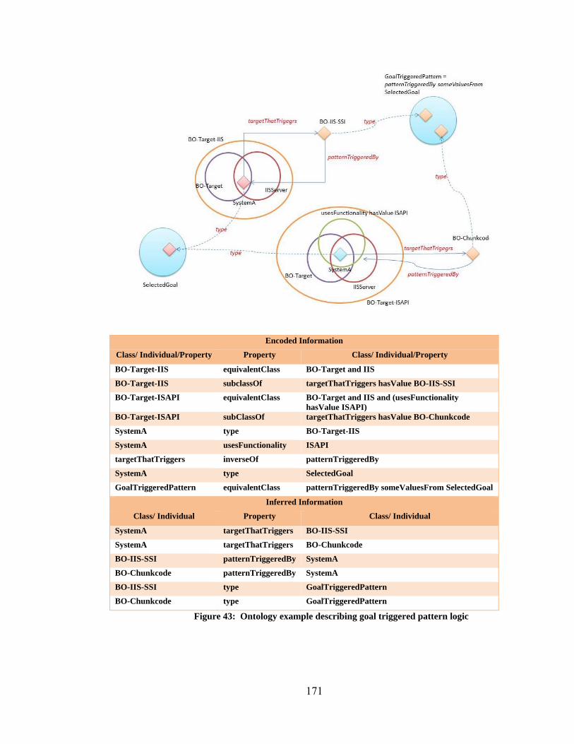
171
Figure 43: Ontology example describing goal triggered pattern logic
Encoded Information
Class/ Individual/Property Property Class/ Individual/Property
BO-Target-IIS equivalentClass BO-Target and IIS
BO-Target-IIS subclassOf targetThatTriggers hasValue BO-IIS-SSI
BO-Target-ISAPI equivalentClass BO-Target and IIS and (usesFunctionality hasValue ISAPI)
BO-Target-ISAPI subClassOf targetThatTriggers hasValue BO-Chunkcode
SystemA type BO-Target-IIS
SystemA usesFunctionality ISAPI
targetThatTriggers inverseOf patternTriggeredBy
SystemA type SelectedGoal
GoalTriggeredPattern equivalentClass patternTriggeredBy someValuesFrom SelectedGoal
Inferred Information
Class/ Individual Property Class/ Individual
SystemA targetThatTriggers BO-IIS-SSI
SystemA targetThatTriggers BO-Chunkcode
BO-IIS-SSI patternTriggeredBy SystemA
BO-Chunkcode patternTriggeredBy SystemA
BO-IIS-SSI type GoalTriggeredPattern
BO-Chunkcode type GoalTriggeredPattern

172
6.5.3.4 Trigger the Threat Pattern
This section describes an example of how the attack patterns are triggered given the
goal or sub-goal information with the example shown below. For ease of presentation,
this logic is described in two Figures. Figure 44 displays steps 1-6 and Figure 45 displays
the steps 7-9
The numbered steps in Figure 44 are explained below.
1. Section 6.4.2.2 described how the target of a pattern is triggered. This section
builds on that logic. The targetThatTriggers property has an inverse property
called patternHasTarget.
2. Section 6.4.2.1 described the structure of the pattern. This structure encodes
information about the effect of the pattern. This information is reproduced here as
BO-IIS-SSI hasEffect PrivillegeEscalation.

173
Figure 44: Example logic for triggering attack pattern – part 1
Encoded Information
Class/ Individual/Property Property Class/ Individual/Property
IISServer targetThatTriggers BO-IIS-SSI
targetThatTriggers inverseOf patternHasTarget
BO-IIS-SSI hasEffect PrivillEscalation
ConnectedHostToWhichAccess-IsNeeded
subclassOf providedByEffect hasValue PrivilEscalation
WindowsServer type ConnectedHostToWhichAccess-IsNeeded
effectProvides inverseOf providedByEffect
patternProvides propertyChainAxiom hasEffect, effectProvides
providedByPattern inverseOf patternProvides
targetThatProvides propertyChainAxiom targetThatTriggers, patternProvides
Inferred Information
Class/Individual Property Class/Individual
PrivillEscalation effectProvides WindowsServer
WindowsServer providedByEffect PrivillEscalation
BO-IIS-SSI patternProvides WindowsServer
WindowsServer providedByPattern BO-IIS-SSI
IIS-Server targetThatProvides WindowsSever

174
3. Conceptually, if an application is hosted on an operating system, one of the ways
to gain access to this host is to execute a privilege escalation10 attack on the
application. This conceptual information is encoded by:
a. Defining an anonymous class as a collection of all individual sub-goals
that are achieved by the privilege escalation effect. This is done by
defining a class using the property restriction providedByEffect to the
value PrivillegeEscalation.
b. Making the class describing the host (for example, the
ConnectedHostToWhichAccessIsNeeded class) a sub-class of this
anonymous superclass.
4. In this example, when an individual, WindowsServer becomes a member of this
ConnectedHostToWhichAccessIsNeeded class, the following can be inferred:
a. WindowsServer is member of the
ConnectedHostToWhichAccessIsNeeded, which is declared as a sub-
class of the anonymous class defined by restriction providedByEffect
hasValue PrivillegeEscalation. Given this, it can be inferred that
WindowsServer meets the membership criteria of the anonymous
superclass. Hence, WindowsServer has to satisfy the property
relationship defined in the membership criteria. From this it can be
inferred that WindowsServer providedByEffect PrivillegeEscalation.
10 The privilege escalation attack exploits any vulnerability on application or software running on an
underlying host machine to gain an elevated access to this host which otherwise is protected from this application or software.

175
b. The property effectProvides is defined as the inverse property of
providedByEffect; it can be inferred that ‘PrivillegeEscalation
effectProvides WindowsServer’
5. The property patternProvides is defined as a chain of property combining
‘hasEffect’ and ‘effectProvides’.
a. This leads to the inference that BO-IIS-SSI patternProvides
WindowsServer.
b. The providedByPattern property is defined as an inverse of
patternProvides. Therefore it can be inferred that WindowsServer
providedByPattern BO-IIS-SSI
6. Finally, the targetThatProvides is defined as a chain of property combining
targetThatTriggers and patternProvides so it can be inferred that IISServer
targetThatProvides WindowsServer.
For ease of presentation, steps 7-12 are described in Figure 45. This shows the
inference of step 5, that BO-IIS-SSI patternProvides WindowsServer.

176
Figure 45: Example logic for triggering attack pattern – part 2
7. The patternTargetHostedOn is defined as a property chain combining the
paternHasTarget and isHostedOn property. It can be inferred that BO-IIS-SSI
pattenTargetHostedOn WindowsServer.
8. hostOfPatternTarget is defined as the inverse property of patternTargetHosteOn,
so it can be inferred that WindowsServer hostOfPatternTarget BO-IIS-SSI.
9. Finally, all these inferences can be combined to define the triggered pattern as.
TriggeredPatternLocToWhichAccessIsNeeded is defined as:
TriggeredPatternLocToWhichAccessIsNeeded =
( (patternHasTarget someValuesFrom TriggeredSubgoal)
and (patternProvides someValuesFrom
(ConnectedHostLocToWhichAccessIsNeeded
Encoded Information
Class/ Individual/Property
Property Class/ Individual/Property
patternTargetHostedOn propertyChainAxiom patternHasTarget, isHostedOn
hostOfPatternTarget inverseOf patternTargetHostedOn

177
and (hostOfThePatternTarget
someValuesFrom Pattern))))
This is equivalent to saying that the pattern (BO-IIS-SSI) can be used to
compromise the “connected host location to which is access is needed”
(WindowsServer) is triggered, if: 1) it targets a “triggered sub-goal” , 2) the IIS
Server is hosted on the Windows Server, and 3) the pattern’s execution can
achieve (provide) this sub-goal.
This example shows how the basic constructs can come together in a specific
situation. The complexity of the attack plan is driven by the interplay of these otherwise
simple constructs. Logic patterns similar to this one are used to define how other attack
patterns could be triggered when information is available.
This Chapter described how Flux triggers the information that can be used for
generating risk scenarios. Next chapter describes CieKI’s centralized algorithms and
attacker behavior ontology.

178
7 Framework Component: CieKI
CieKI (pronounced as psyche) stands for Cognition Induced Kinetic Intelligence. It
consists of centralized algorithms and the attacker behavior ontology. The attacker
behavior ontology encodes the attacker strategy and preferences.
The main purpose of CieKI is to:
1. Insert the attacker decisions in the distributed planning logic (Flux) that triggers
the sub-goals, fingerprinting actions, and the available attacks.
2. Graphically generate the attack plan by querying the triggered information from
Flux, and attacker behavior ontology.
3. Build the attacker’s knowledge state for generating the attack-scenarios. This
knowledge state is used to control what knowledge is triggered by Flux.
CieKI represents the attacker’s decisions points, during the attack process, using a
situational dynamic decision tree. The attacker preferences for these decision points are
encoded using the attacker behavior ontology. CieKI uses this situational decision tree
and attacker preferences to determine the order in which the distributed planning logic
(Flux) is queried.
This chapter describes the situational dynamic decision tree and the attacker behavior
ontology.
7.1 Situational Dynamic Decision Tree
It is important to study how and when the attacker makes decisions during the attack
process, in order to replicate this behavior for automated plan generation. These attacker
decision points are represented using a situational dynamic decision tree. The options

179
available at these decision points depend on the attack situation. The logic flow for the
situational dynamic decision tree is shown in Figure 46 below.
Figure 46: Situational Dynamic Decisison Tree
In Figure 46, the trapezoids refer to the anchor set classes in Flux. If there are any
members in the anchor set, then the corresponding decision point is enabled. Otherwise,
the decision point is blocked until Flux discovers such members. The members of the
1
2
2a
4
5
3
3a
6
7
4a
4b
5
7
7
4c

180
anchor sets become the decision options available to the attacker. The decision point is
shown as the diamond-shaped decision box in Figure 46. This box is the same color as
the trapezoidal anchor set that enables it.
This decision tree logic is explained below. The numbers in this explanation refer to
the component marked with the same number in Figure 46. Note that this numbering does
not indicate the flow of decision sequences. The actual sequence in which the decisions
are made depends on attacker preferences and the attack situation.
1. The decision tree starts with the attacker’s (or red-team’s) selection of a goal,
represented by the decision point “selected goal”. This selected goal may trigger
the “goal triggered FP (fingerprinting) goal”11, “goal triggered subgoal”, or
“goal triggered pattern”.
2. If initially no information is available, only the fingerprinting goals may be
triggered.
a. In this case, the attacker (or red-team) may choose a fingerprinting goal
from the triggered options. The information gathered by executing the
selected fingerprinting option may further trigger the sub-goals and/or
patterns as indicated in Figure 46 above. Note that the effect of
fingerprinting goals is global, since they are used to learn about the
system. The information that can be uncovered, by executing the
fingerprinting goals, can trigger any sub-goals, patterns, or attacks even
though the executed fingerprinting goal is classified as the “goal trigger
fingerprint goal”. CieKI builds the attacker’s knowledge state using the
information discovered by executing fingerprinting goals. 11 In the Figure 48 Fingerprinting is abbreviated to FP for ease of graphical presentation

181
3. The selected goal may trigger potential sub-goals if information about how to
decompose the goal is available, either by executing the fingerprinting goals, or
from a priori knowledge.
a. These triggered sub-goals are available as options for the attacker (or red-
team). When the attacker (or red-team) selects a sub-goal, the “subGoal
triggered FP (fingerprint) goal” is triggered. If the information about how
to decompose the selected sub-goal, or to accomplish them is available,
then “subgoal triggered subgoal” and “subgoal triggered Pattern” are also
triggered.
4. If patterns that may accomplish the selected goal are available, then “goal
triggered patterns” are triggered.
a. The attacker (or red-team) may select a triggered pattern to accomplish the
selected goal based on his/her preference.
b. If a pattern is selected, then the corresponding available attacks are
triggered. The attacker (or red-team) then may select one of the triggered
attacks.
c. If the selected attack accomplishes the goal, then the goal is marked as
accomplished. When this happens, the logic of the tree moves to the
beginning of the decision tree if any more goals or fingerprinting actions
(that may trigger new goals) are available. Note that the attacker (or red-
team) may choose not to use any triggered attacks, if these attacks do not
satisfy his/her preferences.

182
5. A selected sub-goal may further trigger more sub-goals, finger printing goals, or
patterns.
6. Selected fingerprinting goals may provide more information about the system,
which can further trigger sub-goals, patterns, and attacks. Again, note that the
effect of fingerprinting goals is global, since they are used to learn more about the
system.
7. Also similar to “goal triggered pattern”, the “sub-goal triggered pattern”
selection further triggers available attacks whose execution achieves the selected
sub-goal. The accomplishment of sub-goals in turn may achieve the selected goal.
In this case, the control returns to the top of the decision tree if any more goals, or
fingerprinting actions (that may trigger new goals), are available.
CieKI also provides an interface for the red-team to interact with the target network.
This interface is called CieKI Red-team Diary (RTD).This decision diagram is a core part
of CieKI RTD interface. Situational decision tree is used for developing the proposed
framework’s mode 2, 3, and 4 algorithms. Section 4.3.7 introduced these modes of
operation, and Chapter 8 describes them in detail.
7.2 Attacker Behavior Ontology
Attacker strategy and preferences influences the decisions made by the attacker.
Attacker strategy in turn is influenced by the attack’s environmental context and the
attacker’s motivation. This is shown in Figure 47 below.

183
Figure 47: Factors influencing attacker strategy
The same attacker may use a different attack strategy, for example, if the information
to be compromised is located in a military network as opposed to a University lab
network. The attacker strategy is also dependent on the attacker’s motivation. The
attacker may choose different types of attacks, for example, if the motivation was
learning as opposed to getting public attention.
Given the environmental context and attacker motivation, this dissertation encodes
four types of attacker strategies called direct, fastest, prudent, and stealth strategy. Note
that even though this dissertation initially focuses on these four strategies, the proposed
framework’s logic is scalable enough to encode new strategies, or new combinations of
current strategies if needed. This ontology can also be used to encode technological
preferences (for example it can encode if attacker prefers compromising Linux to
Windows).

184
These four strategies are described as:
1. Direct Attack Strategy: In direct attack strategy, the attacker tries to
compromise the system directly, and avoids using other systems as a launching
point of the attack.
2. Fastest Attack Strategy: In fastest strategy, the attacker tries to launch the attack
as soon as possible. An attacker with this strategy may not try to capture detailed
information about the system using fingerprinting, but will instead use only the
minimum amount of information that allows selection of an attack as “good
enough” information. The leap-before-you-look attacker is an example of this
type of attacker. Apart from shortening the information-gathering phase, the
fastest attack strategy may also prefer faster attacks given the option. The fastest
attack strategy is a more constrained direct attack strategy.
3. Prudent Attack Strategy: This strategy is the opposite of the fastest attack
strategy. In this strategy, the attacker tries to gather as much information as
possible before selecting and launching the attack. Given the option, the attacker
using this strategy may select attacks that are more accurate (or reliable).
4. Stealth Attack Strategy: This strategy can be used with any of the above-
mentioned strategies. In this strategy, the attacker prefers stealthy attacks given
the option.
7.2.1 Encoding Attacker Strategy
In order to encode the attacker preference, the attacker’s decision points are first
identified using the situational dynamic decision tree. The attacker’s preferences are then
encoded at these decision points, using the attacker behavior ontology.

185
7.2.1.1 Attacker Decision Points
The attacker’s decision points are shown in Figure 48 below. The decisions made at
these points are driven by the attacker’s strategy. Figure 48 illustrates the decision points
as 11 blocks after removing the successor flow of logic from the decision tree shown in
Figure 46.
Decision points 1 and 7 allow the red-team to select the goal and sub-goal. At
decision points 2 and 8, the red-team may select either the fingerprinting goal, or a
pattern that accomplishes the selected goal or sub-goal, or they may choose to decompose
the goal or sub-goal further. Decision point 6 shows that the selected goal or sub-goal can
be further decomposed into exploiting functionality, connectivity, or attribute sub-goal
types. The decision points 3 and 9 allow the selection of triggered fingerprinting goals.
Decision points 4 and 10 allow the selection of triggered patterns, and decision points 5
and 11 allow the selection of the triggered attacks.

186
Figure 48 : Attacker descision points
1
2
3 4
5
6
7
8
9
10
11

187
7.2.1.2 Attacker Behavior Ontology
Attacker preferences are applicable at these decision points. These preferences are
encoded using attacker behavior ontology. This ontology is created by encoding the
following three logic types.
1. The first type of logic describes the conceptual relationship among the decision
points (or among the options within a decision point), using properties. For
example, the information that exploiting a triggered pattern is faster than
decomposing a goal is encoded as (GoalTriggeredPattern isFasterThan
GoalTriggeredSubgoal). This is shown in Figure 49.
2. The second type of logic associates the properties with a strategy. For example,
the ‘isFasterThan’ property can be used to implement the fastest attack strategy.
The other three strategies have corresponding properties ‘isDirectThan’,
‘isPrudentThan’ and ‘isStealthyThan’.
3. The third type of logic involves defining an abstract anchor property
‘isPreferedThan’ and making one of the properties defined in step 2 a sub-
property of this anchor property, according to the selected strategy. For example,
if the fastest attack strategy is the selected strategy, then the isFasterThan
property is made the sub-property of the isPreferedThan property. If it is stated
that “AttackA isFasterThan AttackB” then using the property relation and
strategy information, it can be inferred that “AttackA isPreferedThan AttackB”.
This ‘isPreferedThan’ property is called an anchor property (conceptually
similar to the anchor class ) because it allows the CieKI algorithms to query this

188
fixed property every time, but the meaning of this property can be changed in real
time to reflect the attacker strategy.
For example, if the strategy is changed from fastest attack to stealthy attack,
then the isStelthierThan property is made the sub-property of the isPreferedThan
property. If it is stated that “AttackB isStelthierThan AttackA”, then it can be
inferred that “AttackB isPreferedThan AttackA”.
This is shown in the Figure 50 below. The blank decision option trapezoid is
filled in real time based on the strategy chosen by the red-team or attacker.
Technological preferences are also encoded using isPreferredThan property.
Figure 49: Attacker strategy driven properties between the decsions points
Figure 50: isPreferredThan property
Note that there is one active strategy for each decision point, but the algorithm
supports choosing hybrid strategies (appropriate combination of the four strategies, or
any new strategies) for different decision points.

189
7.3 Centralized Algorithms
The centralized algorithm inserts the attacker decisions in Flux, and queries its
outcome from Flux. The order of this query is determined by evaluating the attacker
preferences at each decision point represented in the situational decision tree. The
centralized algorithms generate the four types of graphical outputs. These centralized
algorithms and the modes of operations are described in detail in Chapter 8.

190
8 Framework Modes of operation
The proposed framework has five modes of operations. This chapter describes these
modes in detail.
Mode 1: Attack Tree Generation without Attacker Preference: This mode
generates attack trees. It displays all possible ways the attacker can compromise the
information’s confidentiality, integrity, and availability given perfect knowledge of
the system (i.e., it is assumed that the system has been fingerprinted perfectly.) This
mode assumes that all triggered sub-goals are selected by the attacker (i.e., it is
assumed that all possible ways of achieving the goals are selected.)
Mode 2 Attack Scenario Generation Using Red-team: This mode generates the
attack-scenario using red-team. It displays the actual steps taken by the red-team,
given no knowledge of the system (i.e., it is assumed that the red-team has to
fingerprint the system.) This mode provides the available goals, and triggered
fingerprinting goals, sub-goals, patterns, and attacks, as options to the red-team. It
observes the decisions made by red-team, and elicits their theories about attacker
preferences. This mode builds the red-team’s knowledge state, and uses it to trigger
the options available to the red-team.
Mode 3- Automated Attack-scenario Generation: This mode automates
generation of the attack-scenario. It displays the actual steps taken by the attacker,
given no knowledge of the system (i.e., assuming that the attacker has to fingerprint
the system.) This mode uses information about attack goal, and the attacker
preference encoded in attacker behavior ontology to automate the generation of

191
attack-scenarios. This mode builds the attacker’s knowledge state, and uses it to
trigger the options available to the attacker.
Mode 4- Ranked Attack Tree Generation Using Attacker Preferences: This
mode generates ranked attack trees. It displays attack tree, whose branches are
ranked according to the attacker preferences encoded in attacker behavior ontology.
Mode 5- Direct Query: In this mode, Flux can be queried directly to generate
custom outputs.
8.1.1 Attack Tree Generation without Attacker Preference
This section describes the first mode of operation. This mode generates all possible
ways the attacker can compromise the system, given perfect knowledge of the system.
This mode of operation is implemented by:
1. Enabling all encoded system knowledge (i.e., assuming that the system has been
fingerprinted perfectly.)
2. Making all “triggered sub-goals” “selected sub-goals” (i.e., assuming all possible
ways of achieving the goals are selected.)
8.1.1.1 Pseudocode
The pseudocode used for generating the outputs is as shown below:
1. Read the ontology files 2. Retrieve class SelectedGoal 3. For each SelectedGoal 4. Add tree vertex SelectedGoal 5. Retrieve the GoalTriggeredSubGoal instances 6. Determine the SubGoal type for all GoalTriggeredSubGoal instances 7. Add nodes indicating the SubGoal types 8. Add tree edge from SelectedGoal to SubGoal types 9. Add nodes displaying the GoalTriggeredSubGoal instances 10. Add appropriate tree edge from SubGoal type to GoalTriggeredSubGoal 11. For each GoalTriggeredSubgoal instance

192
a. Retrieve the SubGoalTriggeredSubGoal instances b. Determine the SubGoal types for all SubGoalTriggeredSubGoal instances c. Add nodes indicating the SubGoal types d. Add tree edge from GoalTriggeredSubGoal to SubGoal type e. Add nodes displaying the SubGoalTriggeredSubGoal instances f. Add appropriate tree edge from SubGoal type to
SubGoalTriggeredSubGoal instances 12. Retrieve TriggeredPattern
a. For each TriggeredPattern i. Add nodes representing TriggeredPatterns
ii. Add appropriate edge between TriggeredPattern and the target (sub-goal or goal) triggering the pattern.
iii. Retrieve the TriggeredAttacks iv. Add nodes representing TriggeredAttacks v. Add appropriate edge between TriggeredPattern and the
TriggeredAttacks
8.1.1.2 Output
The first mode of operation generates the attack tree as shown in Figure 51. This
graphical output is generated by using a Java graphical software library (and its example),
called Java Universal Network/Graph Framework (JUNG) [140].
In Figure 51, the red nodes represent the goals and sub-goals, orange nodes represent
available patterns, black nodes represent available attacks, and white nodes represent the
type of sub-goals. In order to optimize screen space, the exploit functionality sub-goal is
called FunctionalSub-goal and ConnectedHostToWhichAccessIsNeeded is
summarized as ConnectedHost.
The tree-structure shown in Figure 51 can be collapsed into concentric circles
indicating the cluster of nodes. This is shown in Figure 52. This can be used as a visual
overview to determine which type of sub-goal provides the majority of attacks. Any part
of the tree or graph can be zoomed in and out. The tool also uses “lens” application from
JUNG software library [140], which allows magnification of a specific portion of the
tree. These different features of the output are displayed in Appendix V.

193
Finally, the progression of attacks can also be presented in the form of a radial
output, as shown in Figure 53. In Figure 53, each concentric circle represents how the
goal is broken down to executable attacks that can accomplish the goal. These different
graphical presentations are generated using Java Universal Network/Graph Framework’s
examples [140].

194
Figure 51: Flux Attack Tree Output

195
Figure 52: Flux Attack Tree Spiral Presentation

196
Figure 53: Flux radial output

197
8.1.2 Attack Scenario Generation Using Red-team
This section describes Mode 2 of the proposed framework. This mode provides the
red-team with a graphical interface that allows them to interact with the target network. It
records and displays the actual steps taken by the red-team, given no knowledge of the
system (i.e., assuming that the red-team has to fingerprint the system.) This interface is
part of CieKI and is called CieKI RTD (red team diary). It implements the situational
dynamic decision tree described in Section 7.1.This mode of operation is implemented
by:
1. Providing the red-team possible attack goals, triggered sub-goals, fingerprinting
goals, patterns, and attacks as options. When the red-team selects an action,
CieKI RTD inserts the decision in Flux, and provides the triggered outcome of
action back to the red-team.
2. Building the red-team’s knowledge state using the knowledge discovered
because of red-team’s selection (execution) of a triggered fingerprinting goal.
This knowledge state is used to trigger the sub-goals, patterns, and attacks
(available to the red team) using Flux.
3. Observing the decisions made by the red-team, and eliciting their theories about
attacker strategy and preferences.
8.1.2.1 CieKI RTD Input Interface
This section describes the input interface of the CieKI RTD shown in Figure 54. The
red-team interacts with this interface to make decisions and to view the options available
to them. This interface is divided into multiple input/output panels shown by different
colors. These panels correspond to the attacker decision points in the situational dynamic

198
decision trees. This section describes these panels and the red-team’s interaction with
them.

199
Figure 54: CieKI RTD Interface

200
Goal Selection Panel
The goal selection panel is the first panel that red-team interacts with. Using this
panel, the red-team can select the goal, change the selected goal, and re-activate an old
unaccomplished goal. This panel also displays the information about the systems
compromised by the red-team.
Figure 55 below shows two panels labeled “Available Goal” and “Attacker Access,”
shown in cyan and red.
The “Available Goal” panel displays the possible attack goals available to red-team.
The availability of the goal depends on red-team’s knowledge about the system. This
knowledge can be available a priori (a specific goal may be provided to red-team) or can
be collected by executing fingerprinting goals.
The red-team can select the goal by choosing an option from the "Available Goals"
list and pressing the select goal button. CieKI RTD classifies this selected option as a
member of SelectedGoal class in Flux. Flux uses this information to trigger the “goal
triggered sub-goals”, “goal triggered fingerprinting goals”, or “goal triggered patterns”.
This triggered information is displayed in the sub-goal selection panel (shown in Figure
56), the fingerprinting goal selection panel (shown in Figure 57), and the pattern panel
(displayed in Figure 58).

201
Figure 55 : CieKI RTD – Goal Panel
The panel displaying the “Available Goal” list also contains three more lists called
“Selected Goal”, “Goals Accomplished”, and “Back of your mind”. The goal, when
selected, is moved from the “Available Goal” list to the “Selected Goal” list, and the
“Select Goal” button is disabled. This is because there can be only one active goal in
current implementations of CieKI. However, there can be more than one active selected
sub-goal.
If the red-team decides to change the selected goal before it is accomplished (either
due to inability to accomplish the selected goal or to pursue another goal), by pressing the
“Change Goal” button, it is moved to the “Back of your mind” list. This “back of your
mind” goal can be reactivated by the red-team if needed. One of the objectives of red-
team elicitation is to capture when and why the red-team puts a selected goal on the
“back of your mind” list, and under what circumstances it is reactivated.

202
Goals that are accomplished are moved to the “Goal Accomplished” list. The
“Attacker Access” list shows the systems, applications, or information the red-team has
gained access to by executing actions. At the beginning of the attack scenario, this list
shows ‘None’, indicating attacker has not compromised any systems or information, and
it is updated as the red-team analyst accomplishes goals and sub-goals.
Sub-Goal Selection Panel
Figure 56: CieKI RTD –Sub-Goal Panel
There are two sub-goal selection panels in the CieKI RTD interface, the “goal
triggered sub-goal” and “sub-goal triggered sub-goal” panel. An example of this panel
template is shown in Figure 56. Flux’s triggered sub-goals are presented in the topmost
text box above the select button. These sub-goals are triggered either when a goal (or sub-
goal) is selected or when fingerprinting actions are executed (i.e. when new knowledge is
discovered by the red-team).
When the red-team selects a sub-goal, it is moved to the selected sub-goal text box,
and CieKI RTD classifies it as member of Flux’s “SelectedSubGoal” class. Flux uses this
information to triggers further “sub-goal triggered sub-goals”, “sub-Goal triggered FP

203
goals”, or “sub-goal triggered patterns”. This triggered information is displayed in the
sub-goal selection panel (shown in Figure 56), the fingerprinting goal selection panel
(shown in Figure 57), and the pattern panel (displayed in Figure 58).
If a sub-goal is accomplished by executing attacks, then it is moved to the
“Accomplished Sub-goal” list. Note that only selected sub-goals can trigger the available
patterns, but executing the attacks in the pattern can also accomplish the sub-goals that
are triggered but not selected.
Fingerprinting Goal Panel
The fingerprinting goal panel is shown in Figure 57. There are four such panels in
the CieKI input interface. The fingerprinting goals, triggered by Flux, are displayed in the
text box above the “Execute” button. The fingerprinting goals, when executed, are moved
to the “Accomplished FP Goal” list. The execution of fingerprinting goals provides
information about the target network. CieKI RTD uses this information to build the red-
team’s knowledge state. Flux triggers the available goals, sub-goals, patterns, or attacks,
given the red-team’s knowledge state.
Note that the effect of the fingerpriting goal is global (i..e., a “sub-goal triggered
fingerprining goal” can also trigger “goal triggered patterns”). This is because the
purpose of fingerpriting is to collect information about the target network, and the
usefulness of collected information may not be limilted to a specfic goal (even though the
information collection effort may be triggered by a specific goal).

204
Figure 57: CieKI RTD – Fingerprinting Goal Panel
Pattern and Attack Panel
The pattern panel is shown in Figure 58 below. The triggered patterns are displayed
in the top most textbox. These triggered patterns are further filtered by using the
information about attacker’s access. Once the patterns are triggered, the Threat Ontology
checks to see if the patterns are executable given the current access of the attacker. If the
patterns are executable, then the ontology classifies them as “Executable Patterns”.
These triggered patterns are displayed for information only and cannot be selected.
Only the executable pattern can be selected. This executable pattern is displayed in the
second text box in Figure 58. Once the red-team selects an executable pattern, it is moved
to the selected pattern list, and is classified as a member of Flux’s “SelectedPattern”
class. This classification triggers the corresponding attacks encoded in the pattern. The
triggered attacks and vulnerabilities are shown in Figure 59.

205
Figure 58: CieKI RTD – Pattern Panel
The triggered vulnerabilities are also displayed for information purpose only. Attacks
can be selected to exploit these vulnerabilities. When the triggered attacks are executed,
they are moved to the “Accomplished Attack” list, and the vulnerability exploited by this
attack is moved to the “Exploited Vulnerability” list. The sub-goals and goals
accomplished by executing attacks are also moved to the “Goals Accomplished” and
“Accomplished Sub-Goals” lists. The “Attacker Access” list is also updated to reflect the
accomplished goals and sub-goals. The attack panel is displayed below the vulnerability
panel in Figure 59.

206
Figure 59: CieKI RTD – Attack and Vulnerability Panel
Red-team’s decisions are recorded by the CieKI-RTD as they are made. CieKI RTD
then graphically generates the attack-scenario based on these decisions. The red-team’s
theories about attacker preference and strategies are elicited manually at each decision
points. This elicited information is recorded in the attacker behavior ontology. This
elicited information can be used to automatically generate the attack-scenarios in mode 3
and to rank the attack tree’s branches in mode 4.
8.1.2.2 RTD Pseudocode
The algorithm in the form of a pseudo code is shown below.
I. SELECT: Goal A. ASSERT: Selected Goal in Flux
1. Disable select goal option B. Selected Goal may TRIGGER GoalTriggeredFingerprintGoal or TriggeredPattern or GoalTriggeredSubgoal given the information in Flux

207
1. IF (GoalTriggeredFingerPrintGoal) THEN enable this as the decision to be made ELSE declare no goal triggered fingerprint goal 2. IF (TriggeredPattern) THEN enable this as decision to be made ELSE declare no goal triggered pattern 3. IF (TriggeredSubGoal) THEN enable this as decision to be made ELSE declare no triggered subgoals
II. Repeat A. IF (enabled goal triggered decisions to be made)
1. THEN a) DISPLAY the enabled decisions to be made b) IF Selected (GoalTriggeredFingerPrintGoal) THEN
(1) EXECUTE the goal (2) ASSERT the outcome in Flux
(a) The fingerprint outcome may TRIGGER TriggeredPattern or TriggeredSubgoal given the information in Flux (b) Enable appropriate goal and sub-goal triggered decisions to be made
c) IF Selected (GoalTriggeredSubGoal) THEN (1) ASSERT: Selected Sub-Goal in Flux (2) Selected SubGoal may TRIGGER SubgoalTriggeredFingerprintGoal or TriggeredPattern or SubgoalTriggeredSubgoal given the information in Flux (3) Enable appropriate goal and sub-goal triggered decisions to be made
d) IF selected (ExecutableTriggeredPattern) THEN (1) ASSERT: Selected Pattern in Flux (2) EXECUTE pattern (3) IF (SelectedPattern provides selected Goal) THEN
(a) Declare goal is achieved (b) Updated Attacker Access
B. IF (enabled subgoal triggered decisions to be made) 1. THEN
a) DISPLAY the enabled decisions to be made b) IF selected (SubGoalTriggeredFingerPrintGoal) THEN
(1) EXECUTE the goal (2) ASSERT the outcome in Flux

208
(a) The fingerprint outcome may TRIGGER TriggeredPattern or TriggeredSubgoal given the information in Flux (b) Enable appropriate goal and sub-goal triggered decisions to be made
c) IF selected (SubGoalTriggeredSubGoal) THEN (1) ASSERT: Selected Sub-Goal in Flux (2) Selected SubGoal may TRIGGER SubgoalTriggeredFingerprintGoal or TriggeredPattern or SubgoalTriggeredSubgoal given the information in Flux (3) Enable appropriate goal and sub-goal triggered decisions to be made
d) IF selected (ExecutableTriggeredPattern) THEN (1) ASSERT: Selected Pattern in Flux (2) EXECUTE pattern (3) IF (SelctedPattern provides selected SubGoal or Goal) THEN
(a) Declare goal or sub-goal is achieved (b) Updated Attacker Access
C. IF selected (change Selected Goal) THEN 1. Put current Selected Goal on Back of your Mind Buffer 2. Enable select goal option 3. IF selected (new available goal or Back of your Mind Buffer goal)
a) ASSERT: Selected Goal in Flux (1) Disable select goal option
b) Selected Goal may TRIGGER GoalTriggeredFingerprintGoal or TriggeredPattern or GoalTriggeredSubgoal given the information in Flux
(1) IF (GoalTriggeredFingerPrintGoal) THEN enable this as the decision to be made ELSE declare no goal triggered fingerprint goal (2) IF (TriggeredPattern) THEN enable this as decision to be made ELSE declare no goal triggered pattern (3) IF (TriggeredSubGoal) THEN enable this as decision to be made ELSE declare no triggered subgoals
Until (Red-team terminates execution)

209
8.1.2.3 CieKI RTD Output
RTD generates the attacker scenario representing the actual red-team steps. An
example of this for the case study described in Section 5.4 is as shown in Figure 60
below. These steps are numbered according to the sequence in which they were executed.
The loop shown in Figure 60 indicates that the initial goal was put on the back of your
mind buffer and was reactivated later. This change and re-activation of goals and
backtracking are important aspects of the attacker behavior that are not captured by the
attack tree.
In Figure 60, the red nodes indicate the goals and sub-goals, yellow nodes indicate
fingerprinting action, orange node indicates selection of a pattern, and the black node
indicates execution of attack.
In the scenario displayed in Figure 60, the attacker selects “compromising trade
secret” as the goal. The steps taken by red-team are explained below:
1. The goal has a functional relationship with the MySQLserver, and it is selected
as the sub-goal by the red-team.
2. Because no other information is available, the red-team executes a network scan.
However, because the server hosting the MySQL is in the private network and
protected by a firewall, no information about this selected sub-goal
MySQLServer is available. The network scan however returns information about
a Windows Server, and the applications executing on this server.
3. Since no information about selected sub-goal is available, the red-team analyst
puts the TradeSecret on the “back of your mind buffer” and makes
compromising the discovered WindowsServer a new goal.

210
4. There are executable patterns available to compromise the WindowsServer.
From these patterns, a buffer overflow pattern called BO-SMB, targeting the
implementation of server message block protocol, is selected by the red-team.
5. The BO-SMB pattern and the WindowsServer goal are accomplished by
executing a new (hypothetical) variant of Sasser attack called SasserEq.
6. The red-team then performs a fingerprinting action again from the new locations
they now have access to. The Windows Server in the given example has visibility
into the internal network and provides the information that MySQL Server is
hosted on a Linux Server.
7. The red-team uses this newly discovered information to reactivate the
“compromise trade secret” from the “back of your mind buffer”, making it the
new selected goal.
8. The MySQL Server again becomes the new selected sub-goal to achieve the
“compromise trade secret” goal.
9. The Linux Server hosting this MySQL Server is also triggered and further
selected as a sub-goal.
10. An executable pattern providing unauthorized access to Linux Server is triggered
and selected.
11. This pattern is achieved by executing the “LICQ attack”. Having access to the
Linux Server accomplishes the sub-goal of compromising “MySQL Server”, and
accomplishes the goal of compromising the trade secret stored in it.

211
Figure 60: CieKI RTD Output – Attack-scenario
8.1.2.4 Benefits of CieKI RTD
Traditionally, the red-team has to discover system information as part of the red-
teaming exercise. The red team then uses their attack launching tools to execute proof of
concept attacks12 to achieve a pre-determined goal. The red-team may spend a significant
amount of time discovering system information by executing fingerprinting actions, and
executing attacks to compromise the discovered vulnerabilities.
The main value of using the red-team, however, lies in their theories about attacker
behavior and not in their ability to execute the fingerprinting actions and attacks.
In the proposed framework, the red-team interacts with the target network to be
compromised using the CieKI RTD interface. This interface isolates the underlying target
network from the red-team.
CieKI RTD provides the red-team available goals, and triggered sub-goals,
fingerprinting actions, patterns, and attacks as options. When the red-team selects an
action, it inserts the decision in Flux, and provides the triggered outcome of action back
12 Note that the red team carries out an attack only if it is asked to do so.

212
to the red-team. CieKI RTD can also be integrated with scanning and attack launching
tool like Metasploit [131] .
The advantage of this tool is:
1. It eliminates the red-team’s burden of executing fingerprinting actions, and
launching attacks. This allows red-teams more time to develop and test attacker
behavior theories.
2. CieKI RTD facilitates expert theory elicitation. Using this interface, the
elicitation analyst can observe and ask questions about the red-team’s selection of
actions. This allows the elicitation analyst to develop the attacker preference
ontology. The elicited ontology can be used for automatically generating the
attack plans.
3. In secured facilities, it may not be possible to give the red-team access to the
actual target network. The proposed framework’s red-team interface allows
abstracting the actual system information, thus giving the red-team only the need-
to-know information.
4. New proof-of-concept attacks generated by the red-team can be added to the
threat ontology as new actions.
8.1.3 Attack Scenario Generation Using Encoded Attacker Behavior Theory
This mode automates generation of the attack-scenario. It displays the actual steps
taken by the attacker, given no knowledge of the system (i.e., assuming that the attacker
has to fingerprint the system.) This mode uses information about attack goal, and the
attacker preference encoded in attacker behavior ontology to automate the generation of
attack-scenarios.

213
This mode of operation is implemented by:
1. Querying the triggered information from Flux using the attacker’s goal and
knowledge state. The order of query itself is determined by querying the attacker
behavior ontology to evaluate the attacker’s preferred decisions at each decision
point in the situational dynamic decision tree.
2. Building the attacker’s knowledge state using the knowledge discovered because
of attacker’s selection (execution) of a triggered fingerprinting action. Similar to
Mode 2, the attacker’s knowledge state is used to control the information that can
be triggered by the distributed logic. Unlike Mode 2, the attacker’s fingerprinting
actions are chosen by the Mode 3 algorithm based on encoded attacker’s
preferences and need for information.
This mode generates the attack-scenario similar to the one generated by CieKI RTD.
However, each time a goal is changed, the scenario leading to this goal change is
displayed in a new scenario graph window. The example scenario is displayed in three
windows, shown in Figure 61-63, indicating that the attack goal was changed two times
in this example. The scenario within each window (or within each goal) continues until
either the goal is changed, or until it is accomplished, or until the algorithm declares that
the goal cannot be accomplished. Figure 61 shows the scenario fragment in which the
available fingerprinting goals were tried, but the information available could not
decompose or accomplish the sub-goal “MySQL Server”. Figure 62 shows the
continuation of this scenario after putting the “compromise trade secret” goal on the
“back of your mind” buffer and making WindowsServer the new selected goal. This
ends when the WindowsServer goal is accomplished. Figure 63 shows the continuation

214
of this scenario after the Windows Server is compromised, and the “compromise trade
secret” goal is reactivated.
Figure 61: Automated scenario generation output showing that selected goal cannot be
achieved
Figure 62: Automated scenario generation output after changing goal

215
Figure 63: Automated scenario generation output after reactivating initial goal
8.1.4 Attack Tree Generation Using Attacker Behavior
This mode of operation ranks the attack tree generated in the mode described in 5.5.1
using the attacker preference. This is shown in Figure 64. It shows which branch of the
attack tree is preferred by the attacker. The Flux’s graphical algorithm is modified to
query the preferences of the attacker encoded in attacker behavior ontology to rank the
branches of the tree.

216
Figure 64 Ranked attack tree
8.1.5 Direct Query
Another way to retrieve information from Flux is to use query tools to extract
specific information directly. This is shown with an example of querying the Flux sets
directly using an ontology query tool called the “DL Query”[141]. Figure 65 (a) below
shows the output of querying the selected goal class and (b) shows an example of
querying a restriction class.

217
(a)
(b)
Figure 65: Direct query of Flux knowledgebase
Figure 65 section (a) describes the members of the class SelectedGoal. In this tool,
the individuals are called instances. Section (b) displays the outcome of the intersection
of restriction classes encoded as (patternHasTarget hasValue IISServer), and the
TriggeredPattern class.
Direct queries can be used to create custom graphical presentations. One possible
custom graphical representation allows monitoring the size of the anchor sets. The size of

218
the anchor sets increases or decreases based on the situation and information availability.
The system administrators currently monitor the availability of new vulnerabilities or
attacks almost on the daily basis. Using Flux, the system administrators can monitor how
these vulnerabilities and attacks may be used in the attack plans targeting the information
they are trying to protect.

219
9 Framework Evaluation and Comparison
This chapter compares the proposed framework with manual attack tree and
automated vulnerability graph generation frameworks. This comparison is done using the
cyber-security domain requirements identified in Section 3.4, and by using the case study
described in Section 5.4.
9.1 Cyber-security Domain Requirements Comparison
This section compares the proposed framework with the manual attack tree and
automated vulnerability graph generation frameworks using the cyber-security domain
requirements.
9.1.1 Domain Dynamicity
These dynamicity requirements suggest that the risk scenario generation framework
should assume that information is incomplete and update the risk scenarios when new
information is available. The proposed framework generates the risk scenarios using open
world reasoning assuming that information is incomplete. The proposed framework also
uses real-time information as it becomes available to generate these risk scenarios.
The distributed planning logic also meets the following three knowledge
representation requirements:
1. Dispersed Information Sources: The cyber-security domain information (For
example, information about software systems characteristics, vulnerabilities, and
attacks, attack theories etc.) may be generated by multiple sources dispersed in
space and time. The ontology language[110, 114] used in this dissertation can
capture and combine the information from these dispersed sources.

220
The vulnerability graph frameworks capture and use limited information
(primarily about the presence of vulnerability, connectivity between software
systems, attacker’s initial privileges, and the privileges gained by exploiting the
vulnerabilities). Some vulnerability graph generation frameworks [81, 82, 87, 89]
can capture information about known vulnerabilities using vulnerability scanning
tools, and/or vulnerability databases.
2. Dynamic Knowledgebase: One of the challenges of the vulnerability graph
generation methods is that they require an explicit encoding of the information a
priori (before executing the planning algorithm). Any change in information as
well as availability of new information is incorporated by re-capturing and re-
encoding the information, and re-executing the planning algorithm. The proposed
framework overcomes this by using the information, as it becomes available, to
trigger the information relevant (for example, sub-goals, the fingerprinting
actions, the available attacks etc.) for generating the risk scenarios.
3. Incomplete Information: Current vulnerability graph generation methods using
traditional knowledgebase and planning algorithms assumes that information is
complete, there are no unknowns, and whatever information is not explicitly
stated is false. For example, if information about vulnerability is not stored in the
knowledgebase, then it is assumed that such vulnerability does not exist. This
assumption may not valid in the cyber-security domain.
The proposed framework’s logic overcomes this limitation by assuming that
information is incomplete and new information may be available. The proposed

221
framework uses only the information that is explicitly stated without making any
assumption about the information that is not encoded.
In summary, the proposed framework assumes that information is incomplete, when
new information is available or if the encoded information changes, the proposed
framework captures, combines and uses it to generate the risk scenarios in real time.
9.1.2 Attacker Behavior
The proposed framework captures the logic behind why the attacker may exploit any
available opportunities. The proposed framework generates attack plans by capturing
attacker behavior. The distributed logic captures and emulates the attacker thought
process for decomposing goals (and sub-goals) and for discovering and exploiting
opportunities provided by the target network. The proposed framework captures and uses
the attacker’s motivation, strategy, and preferences for generating the risk scenarios. In
accordance with the attacker’s exploratory nature, the proposed framework assumes that
the attacker may discover knowledge during the attack process. This knowledge
discovery not only guides the attack plan but it also may change attacker’s initial goal.
The proposed framework builds the attacker’s knowledge state for controlling the
knowledge that can be triggered by the distributed logic for generating risk scenarios.
Current automated vulnerability graph generation methods describe how the known
vulnerabilities may be exploited, but they do not capture why the attacker may exploit
these vulnerabilities, apart from the fact that they are available. These methods do not
consider attacker behavior (attacker’s motivation, strategy, preferences, thought process,
exploratory nature) for generating risk scenarios.

222
9.1.3 Expert Theory
The proposed framework allows eliciting and encoding expert theories about attack
and attacker behavior. It generates the risk scenarios using these theories. This explicit
encoding of expert theories allows communicating and validating these theories. The
proposed framework also allows experts to test the impact of their theories, and it can be
used to calibrate the experts. This is described in detail in Section 10.2.3.
The main value of using the red team is in their theories about attacker behavior.
Current manual attack risk scenarios are generated by red teams using their theories of
attacker behavior. This output (in the form of risk scenarios) abstracts the expert’s
attacker behavior theories, while summarizing only the actions that the attacker may take
in the risk scenario. If the risk scenarios are generated without explicitly stated
underlying theories, then the opportunity to validate and re-use accurate theories, or to
update inaccurate theories is lost. The vulnerability graph generation methods does not
elicit, use, or validate expert theories.
9.1.4 Automation
Today’s technology infrastructure consists of a large number of software systems. In
addition, a large number of attacks and vulnerabilities exist. Consequently, the
vulnerability graph may have hundreds of nodes. To capture this vast amount of
information, the cyber-security risk scenario generation needs to be automated.
Automation is not only required because of the scale of the risk scenario, but it is also
needed to capture the domain dynamicity. This section compares the frameworks using
these automation requirements.

223
1. Completeness: The vulnerability graph represents all possible ways the
attacker can gain restricted privileges (or circumvent a security property). In
the case of manual attack tree generation, the completeness of the attack tree
is limited to the analyst's ability to identify the attack-scenarios. The
proposed framework’s attack tree generates all possible ways the attack goal
of compromising information can be achieved.
2. Repeatability: The automated vulnerability graph generation framework
and the proposed framework generate repeatable output given the same
information as input. The outcome of manual attack tree generation may vary
even with the same input information, depending on the skills and knowledge
of the analyst generating the output.
3. Scalability: The scalability of an algorithm is limited by increase in run time
(the time it takes for the algorithm to execute) as more inputs are added.
According to [1], most of the vulnerability graph generation frameworks have
exponential run time growth (run time grows exponentially). The algorithm
described by Ammann et al [85] has the polynomial run time.
The OWL language used in this dissertation (OWL DL) has the worst-case
exponential complexity [142]. However, new versions of OWL languages
have already reduced this worst-case complexity to the polynomial
time[142]. The main difference between the proposed framework and
vulnerability graph algorithm is in how they handle new knowledge. Current
vulnerability graph generation framework has to re-capture and re-encode the
knowledge and re-execute the algorithm when knowledge changes. This is a

224
time consuming process. In the proposed framework, new knowledge can be
incrementally classified into appropriate classes. This incremental reasoning
may decrease the classification time significantly.
The proposed framework’s logic is also scalable i.e. new logic can be added
when new domain understanding is available.
4. Analyst Dependence: The manual attack tree generation’s quality,
completeness, and repeatability are dependent on the analyst. The automated
vulnerability graph and attack plan generation framework have limited
analyst dependence for generating the tree.
These comparisons are summarized in Table 10.

225
Table 10: Comparison of risk scenario generation frameworks
Comparison Criteria Vulnerability Graph Red team Flux CieKI
Domain Dynamicity
Distributed Information
Can capture information from automated tools like vulnerability scanners and vulnerability database.
Yes Can capture diverse information from distributed sources. Supports information fusion to combine information.
Dynamic Knowledgebase
Requires re-capturing and re-encoding information, and re-executing algorithm when information changes.
Requires manually updating the attack tree
Captures dynamic information when it becomes available. Uses this captured information to trigger the information relevant for generating risk scenarios.
Incomplete Information
Assumes information is complete, and available a priori.
Yes Assumes information is incomplete and is not available a priori
Attacker Behavior
Does not capture or use attacker behavior theories.
Yes Emulates attacker thought process for decomposing goals and sub-goals, and discovering and exploiting opportunities.
Captures and uses the attacker’s motivation, strategy, and preferences. Assumes that the attacker discovers knowledge during the attack process. This knowledge discovery may also change attacker’s initial goal. It builds and uses the attacker’s knowledge state for generating attack-scenarios.
Expert Theories Does not capture or use expert theories
Yes Captures and uses expert theories about attacker behavior. Supports expert theory validation and calibration.
Automation Completeness Displays all possible ways the vulnerabilities can be exploited.
Limited to analyst's abilities.
Displays all possible ways the attacker goal can be achieved.
Displays all possible ways the attacker goal can be achieved given attacker preferences.
Repeatability Yes No Yes Yes Scalability Best case polynomial runtime.
New knowledge requires re-capturing, re-encoding and re-executing algorithms.
Yes Best case polynomial runtime. New knowledge is captured incrementally. The risk scenario generation logic of the proposed framework is also scalable.
Analyst Dependence
No Yes No

226
9.2 Case Study Comparison
The algorithms of vulnerability graph generation frameworks and the proposed
framework were compared in detail in Chapter 3 and 4. This section compares the
proposed framework with the manual attack tree and automated vulnerability graph
generation frameworks by their, input, and outputs, using the case study described in
Section 5.4.
The input and output encoding described in Sheyner [81] is used as an example to
illustrate the vulnerability graph generation framework’s input and output. This
framework was selected because:
1. Even though the current vulnerability graph generation framework uses
different algorithm or different encoding language, at high level the structure
of their input (using prerequisites and effects) and outputs (in the form of
attack graph) are similar.
2. Sheyner’s [81] approach encodes attacker’s fingerprinting actions (using
system state, pre-requisites, and effects). This allows comparing this
approach with the proposed framework’s encoding of the attacker’s
knowledge acquisition.
3. Sheyner [81] describes input encoding of all actions and output using a
detailed case study that can be used for comparison. This case study is reused
in this dissertation.

227
9.2.1 Comparison of Input
This section compares the frameworks by the type of information used as the input,
and the process used to encode these inputs.
9.2.1.1 Vulnerability Graph Generation Framework Input
The vulnerability graph frameworks primarily uses information about the presence of
vulnerability, privilege gained by exploiting these vulnerabilities, connectivity between
software systems, actions that can exploit these vulnerabilities, and the initial system state
(including attacker’s initial privileges). The actions are encoded using prerequisites and
effects[1]. The action prerequisites are used to identify the system in which they are
applicable. Action effects encode the state that the system will be in after the action
execution.
The challenges of encoding input in this manner are:
Hard coding of fingerprinting action using pre-requisite and system state is
susceptible to errors.
Input encoding of current vulnerability graph generation frameworks cannot
semantically differentiate the effects of a multi-effect action. Capturing the
semantics of multi-effect action, and the attacker behavior associated with it
is important to generate the real-life risk scenarios.
The vulnerability graph generation frameworks often make simplifying
assumption to decrease the search space or to increase the scalability of
algorithm. These assumptions may not reflect the real life scenario.
Manual input encoding might be susceptible to cognitive errors.

228
This section illustrates an example of the input and output encoding using the
encoding described in Sheyner [81]. It then details the challenge of input encoding.
Example of Input Encoding
Encoding Presence of Vulnerability
Sheyner’s framework [81] captures the presence of vulnerabilities by encoding
whether a vulnerable application is executing on the software system or not. This
information is captured using a Boolean variable, as indicated in the Table 11 below.
Pre-requisite Variable
Description
w3svch Indicates that IIS web service running on host ‘h’[81]
squidh Indicates that Squid proxy running on host ‘h’[81]
licqh Indicates that LICQ running on host ‘h’[81]
scriptingh Indicates that HTML scripting is enabled on host ‘h’[81]
vul-ath Indicates that “at” program is vulnerable to buffer overflow on host ‘h’[81]
Table 11: Vulnerabilty graph geenration method’s encoding of vulnerability information - source of
data [81, 82]
Encoding Connectivity between Software Systems
The connectivity between software systems is represented using connectivity matrix.
The connectivity matrix is shown in Table 12 below. The Table shows three type of
connectivity between two software systems encoded using Boolean variables. These
Boolean variables are in “x,x,x” format. In this, ‘x’ is substituted with ‘y’ (yes) if the two

229
software systems are connected and is substituted with ‘n’ if they are not. The three
variables capture whether the two software systems are connected by 1) a physical link,
2) port number13 80, and 3) port number 5190. In real life, the two software systems can
be connected using more than two ports. In theory, two software systems can be
interconnected using any of the 65,536 ports. The technology infrastructure also has
hundreds of software systems. As a result, the connectivity matrix can grow very rapidly.
Host Intruder IIS Web Server Windows Linux
Intruder y,y,y y,y,n n,n,n n,n,n
IIS Web Server y,n,n y,y,y y,y,y y,y,y
Windows n,n,n y,y,n y,y,y y,y,y
Linux n,n,n y,y,n y,y,y y,y,y
Table 12: Vulnerability graph connectivity matrix - source of data [81, 82]
Encoding Actions that Exploit the Vulnerability
This section describes how the actions are encoded using prerequisites and effects.
These actions have four components intruder prerequisites, network prerequisites,
intruder effects, and network effects.
The intruder prerequisites capture the necessary privileges that the intruder must
have in order to execute this action. This is encoded by function plvl(x), which captures
the intruder’s privilege level (plvl) on host x.
13 In transmission protocols, a port is an endpoint to a logical connection between two computers.
These ports are numbered from 0 to 65536. Many well-known applications use a predetermined port number to accept connections from clients. For example, web serves uses port number 80 to accept connections from clients.

230
The network prerequisites encode the presence (or absence) of a vulnerable
application, and reachability of this vulnerable application (or software system) from the
source of attack, or any other specific conditions on target network. This reachability is
encoded by function R(S; T; p) which captures that host ‘T’ (target) is reachable from
host ‘S’ on port ‘p’. Some vulnerability graph generation framework calculates this
reachability using firewall and router rules [89, 143], or by using [87] vulnerability
scanning tools .
Intruder and network effects are encoded by a change in system state (Example of
system states are “scanning done”, “vulnerable service not executing”, etc.).
Sheyner [81] requires the actions to be encoded in the format shown in Figure 66
below.
Figure 66: Action Template
The encoding of four actions described in the case study used in this dissertation is
shown in the Table 13 below. These action encoding is adapted from [81].

231
Action Name IIS-buffer-overflow
Squid-port-scan LICQ-remote-to-use
Local-setuid-buffer-overflow
Description Gives the attacker root privilege on target.
Exploits vulnerability in Squid web proxy to conduct a port scan
Gives a remote user a user level privilege on the target machine.
Exploits buffer overflow vulnerability on a setuid root file to gain root access
Intruder preconditions
plvl(S) ≥ user plvl(S) = user plvl(S) ≥ user plvl(T) = user
plvl(T) < root ⌐scan plvl(T) = none
scan
Network preconditions
w3svcT squidT licqT vul-atT
R(S; T; 80) R(S; T; 80) R(S; T; 5190)
Intruder effects plvl(T) = root scan plvl(T) = user plvl(T) = root
Network effects ⌐w3svcT Table 13: Action encoding - source of data [81]
Sheyner [81] uses a binary state variable to represent the system state before
fingerprinting (represented as “⌐ scan”) and after fingerprinting (represented as “scan”).
This state variable is encoded as a prerequisite to action LICQ-remote-to-use shown in
Table 13.
Encoding Initial System State
The initial state is encoded as the system state in which 1) vulnerable applications,
shown in Table 11, are executing, 2) the intruder has “root” access only on his own
machine, and 3) initially no fingerprinting was performed so the ‘scan’ variable is set to
false (⌐ scan).
Challenges of Input Information encoding
The challenges of encoding information in this manner are explained below.

232
Encoding Fingerprinting Actions
Hard coding of fingerprinting action using pre-requisite and system state is
susceptible to errors. An example of this action encoding is shown in Table 13. This
encoding has a hidden assumption, which if removed may not generate any attack plans.
This is explained by an example taken from [81] that is described below.
In this example, it is assumed that no fingerprinting (⌐scan) was performed initially,
and the attacker has user level access to the web server. The only action available in this
situation is “action IIS-Buffer-Overflow” shown in Table 13. Since this is the only action
available the vulnerability graph generation algorithm selects this action (exploits the
buffer overflow vulnerability to gain root access on this web server). The system state
after executing this action is still (⌐scan) and the only other action available to the
attacker in this state is called “action squid-port-scan”. This action is available because
its pre-requisites system state is encoded as (⌐scan). Execution of this action changes the
state to ‘scan’. This new system state enables the execution of actions whose pre-requisite
requires the system to be in ‘scan’ state.
The vulnerability graph using this encoding may select the SQUID scan vulnerability
using the above-described logic. However, in real life if the attacker was in similar
situation, how would he/she know to target the machine running the SQUID Proxy Server
(located in the private network protected by firewall) if he/she does not know that this
machine exists (because no scans are done yet)? In real life, either the attacker cannot do
anything (as he/she does not have the knowledge), or he/she will have to use some other
scanning action to discover this SQUID proxy in first place. If the attacker uses any other
scanning action to discover the SQUID Proxy Server may also discover other

233
opportunities for executing action (by potentially changing the state of the system to
‘scan’), and therefore making exploiting the SQUID vulnerability unnecessary.
The hard coding of fingerprint actions also implicitly links the action with a specific
network configuration (i.e., the reason Linux vulnerability was hard-coded with ‘scan’
because they were inside the private network). This will require re-encoding the actions
whenever the network configuration changes. For example, if the IIS Server is relocated
to the private network from the DMZ , the actions exploiting its vulnerabilities will
require re-encoding by adding a ‘scan’ to their prerequisites.
Multi-effect Actions
It is challenging to encode the actions with multiple effects in current vulnerability
graph generation methods. For example, buffer overflow vulnerability can be used to gain
unauthorized access to the system as well as to crash the program against which it is
executed. These two are separate effects that can be used differently in different attacker
goals. In the current vulnerability graph generation framework, a single action encoding
is used to capture both effects of multi-effect actions. An example of this is shown in
Table 13. This is true syntactically as the action can produce both the effects. However,
in real life the attacker trying to gain remote access to the machine is doing so to use it as
a precursor to some form of follow up activity (for example, to launch further attacks or
to gain access to trade secret information). Crashing the program and simultaneously
gaining access to it may counter this goal of the attacker.
The attacker’s next applicable actions may be encoded with the pre-requisites
requiring the service to be available and compromised. Both of these conditions may not
be met by executing (selecting) the multi-effect action as it is currently encoded.
234
The attacker may also select both the effects when needed, but this selection is
optional and it is driven by the goal of the attacker. Furthermore, gaining access to a
target using buffer overflow may require higher attacker skills than crashing the service.
The input encoding of current vulnerability graph generation framework cannot
semantically differentiate the effects of a multi-effect action. The current syntactic model
does not allow selecting only the appropriate effect based on the attacker’s goal and
situation. Capturing the semantics of multi-effect action, and the attacker behavior
associated with it is important to generate the real-life risk scenarios.
Simplifying Assumptions
The vulnerability graph generation frameworks often make simplifying assumptions
to decrease the search space or to increase the scalability of algorithm. These assumptions
may not reflect the real life scenario.
One such assumption called monotonicty was described in Table 7. Under this
assumption [85] , 1) the precondition of an exploit, once satisfied, never becomes
unsatisfied, and 2) the negation operator cannot used to express the precondition. Simply
put monotonicity assumes that the attacker never backtracks [85]. This assumption may
not reflect the real-life attacker behavior.
Another simplifying assumption is made for grouping information together to
decrease the search space of the algorithm. One of the challenges of the cyber-security
domain is that a large number of attacks and vulnerabilities exist. Sheyner addresses this
concern by [81] assuming that multiple instances of vulnerabilities can be captured by
using a single generic action. For example, under this assumption all buffer overflow
vulnerabilities in an IIS Server can be captured by a single action. This assumption does

235
not reflect reality, where different types of vulnerabilities are available to attackers in
different situations. These vulnerabilities can have different impacts and can be exploited
using different attacks.
This can be explained with an example of three buffer overflow vulnerabilities in the
IIS Server called CAN-2002-0147[144], CAN-2001-0506 [145], and CVE-2002-0364
[146]. CAN-2002-0147 is only applicable if the IIS Server is using ASP extensions, and
it generates a denial of service (DoS) impact when executed. CAN-2001-0506 and CVE-
2002-0364 may lead to the same effect of privilege escalation, but are available to the
attacker in different situations. CAN-2001-0506 is only available to the attacker when the
IIS is using the Server Side Include (SSI) directives. It may not be possible to use these
vulnerabilities interchangeably.
That being said, it is possible to group together vulnerabilities and attacks, but not as
substitutes for each other. This grouping can be done to categorize similar vulnerabilities
and attacks in order to study and encode how they differ. Attack patterns often group
similar vulnerabilities and attacks. These patterns describe the template of an attack and
identify the basic steps the attacker may have to carry out to execute these types of attack.
In summary, it is possible to group together attacks and vulnerabilities, but this
grouping may not support the inference that the members of the group are
interchangeable in an attack plan.

236
Encoding the Actions Manually
The manual encoding of actions in vulnerability graphs is susceptible to the
following types of errors.
1. The analyst may accidently encode situation specific knowledge (or inferences)
using his/her general cyber-security knowledge. For example, it is well known that web
servers (especially the ones hosting the organization’s websites) in DMZ are easy to find
(may not require much fingerprinting to locate them). Consequently, the actions attacking
these servers in DMZ may be encoded using the pre-requisite of system state assuming
no fingerprinting is required (described by system state ‘⌐scan’). This knowledge may
remain hard coded even if the situation changes (for example if the web server is moved
to the internal private network from the DMZ). This accidental encoding of situation
specific knowledge may not reflect the reality or may limit the scope of hard-coded the
action.
2. The analyst may assume the algorithm to know what is commonly known in the
cyber-security domain. This also may limit the application of the algorithm.
3. The analyst, while making the modeling decision of what to include in the
prerequisites, may subconsciously think through the attack plan to be generated (i.e.,
instead of encoding each action independently, the analyst may think through how these
actions interplay with each other). This may lead to encoding hidden assumptions in
action prerequisites and effects that may not hold true in all scenarios.
These issues are exacerbated in real life, where the analyst or defender has to model
hundreds of actions. Also in real world situations, the action models will be generated by

237
different analysts over a period. Hence, these actions modeled should be flexible enough
to be accurately integrated together in any (appropriate) risk scenarios.
9.2.1.2 Proposed Framework Input
The proposed framework’s input encoding was explained in detail in Chapter 6. The
proposed framework does not encode the actions by prerequisites and effects; instead, it
encodes the logic of cyber-security domain.
Encoding Fingerprinting Actions
The proposed framework also captures the attacker’s exploratory more accurately. In
accordance with this exploratory nature, the proposed framework assumes that the
attacker may discover knowledge during the attack process. This knowledge discovery
not only guides the risk scenario but it also may change attacker’s initial goal. The
proposed framework builds this attacker’s knowledge state for controlling the knowledge
that can be used for generating attack-scenarios. Fingerprinting (or knowledge
acquisition) is also modeled as a situational sub-goal. This fingerprinting goal is triggered
based on the attacker strategy, the decisions made by the attacker and the attacker’s
knowledge state.
Multi-effect Actions
The proposed framework captures the semantics of multi-effect actions and triggers
the action with appropriate effects based on the attacker’s goal and situation. This allows
attacker (or red-team) to choose the effect that is needed to reflect his/her goal, strategy,
and preferences. The example logic of triggering multi-effect buffer overflow action is
explained in Section 6.5.3.

238
Simplifying Assumptions
The proposed framework does not make simplifying assumptions that may restrict
the applicability of the framework. The proposed framework assumes that the attacker
may backtrack, abandon the scenario, or change the goals in accordance with the
available opportunities. The proposed framework encodes the detailed logic of the
vulnerability without grouping them together. This logic can capture how different
vulnerabilities are available to the attacker in different situations. This encoding is
described in detail in section 6.4.2.2, using the example of the IIS server vulnerabilities.
Encoding the Actions Manually
The proposed framework can captures the cyber-security domain knowledge from
diverse sources. These sources can provide the information without having to think (or
know) about how it will be used in the risk scenario generation. This knowledge is also
encoded independent of the risk scenario generation logic. The risk scenarios are
generated by dynamically combining the encoded information in accordance with the
attacker behavior (i.e. by emulating the attacker’s interaction with the target
environment). This avoids the challenges of encoding actions manually.
9.2.2 Comparison of Output
This section compares the output generated by different frameworks using the case
study described in Section 5.4. Note that the case study described in Section 5.4 slightly
modifies the case study described in [81]. For example, given the challenges of using the
SQUID proxy action described in Section 9.2.1.1, this action was removed from the case
study.

239
9.2.2.1 Manual Attack Tree Output
A manually generated attack tree for the case study described in Chapter 5 is shown
in Figure 67 below. This tree was drawn manually using the guidelines provided by
Schneier [72], described in Section 3.5.2.1. This tree shows the different ways of stealing
the “trade secret” information.
Figure 67: Case Study - Manual Attack Tree Output
9.2.2.2 Vulnerability Graph Generation Framework Output
The output of the vulnerability graph is manually constructed using the graph
generation algorithm and is represented in Figure 68 below. In this tree, the attacker first
exploits vulnerabilities in the IIS Server and the Windows Server. The attacker then

240
exploits vulnerability in the LICQ application, or exploits buffer overflow vulnerability in
a Linux Server to gain the root privileges on the Linux Server.
Figure 68: Case study - vulnerability graph
The vulnerability graph framework also generates a set of critical actions, whose
elimination will isolate the end state from the initial state. However, this critical set of
actions is generated assuming that there are no unknowns. This assumption along with
the attacker’s adaptability may produce counter intuitive results. To explain this, SQUID
action is added back to the scenarios. The vulnerability graph, with the addition of the
SQUID action, is shown in Figure 69.
Sheyner’s critical set analysis[81] of this vulnerability graph identifies SQUID
scanning action as the single critical action to eliminate. There is “known unknown”
knowledge in the cyber-security community that the attacker can fingerprint some
software systems using unknown (or unknowable) methods (for example, social
engineering, dumpster diving, network packet sniffing).This means that the conclusion

241
drawn assuming that the only fingerprinting action available to the attacker is the SQUID
scanning action, may not be true. In reality, given this known unknown, the system
administrators (or defenders) would prefer patching the Linux Server and LICQ
vulnerabilities before patching the SQUID scanning action vulnerability. Hence, the
vulnerability graph framework may produce counter-intuitive results assuming that there
are no unknowns in cyber-security domain.
Figure 69: Vulnerability graph after adding SQUID scan action
The proposed framework generates the attack plans assuming that there are
unknowns in the cyber-security domain. The proposed framework’s reasoning assuming
incomplete knowledge (open world reasoning) does not conclude that SQUID scanning
action is the only action available to the attacker. It however, can use this knowledge to
generate the risk scenario showing how this action can be used, if the attacker chooses to
use this action.

242
9.2.2.3 Proposed Framework Output
The proposed framework’s modes of operations and outputs were described in detail
in Chapter 8. These outputs are reproduced here.
The attack tree generated by the first mode of operation is shown in Figure 70 below.
This attack tree shows the goal at the top. This goal is decomposed into a functional sub-
goal compromising the MySQL Server. This MySQL Server can be attacked by using the
trusted hosts (WindowsServer-Archie), connected applications (IIS Server, LICQ, and
SQUID Proxy), or the connected hosts (Windows Server and the Linux Server). The red
nodes represent the goals and sub-goals, orange nodes represent the availability of
patterns to accomplish the goal or sub-goals, and black nodes represent the availability of
attack to execute the patterns. The white nodes represent the type of sub-goal.
Figure 70: Case study- attack tree
Note that the proposed framework does not prune the branches of the tree if
complete information is not available. For example, the WindowsServer-Archie does not

243
have a threat pattern associated with it but this branch is not pruned, because such threat
pattern may become available in future, or it may already exist without the knowledge of
the framework (i.e., there may be a known unknown pattern). Also note that the pattern is
attached to the sub-goal node that of interest to the attacker. For example, the BO-IIS-SSI
pattern technically targets the IIS Server, but it is used to achieve the attacker’s sub-goal
of gaining unauthorized access to the Windows Server. Hence, the pattern node BO-IIS-
SSI is attached to the sub-goal Windows Server in this example. The information that
BO-IIS-SSI technically attacks the IIS Server is not lost and can be used for patching the
IIS server, or can also be displayed in the attack tree if needed.
The attack scenarios showing the actual steps taken by the red-team (or attacker), are
shown in Figure 71 below. This output is generated by modes two and three of the
proposed framework.
Figure 71: Case study - attack-scenario
Attacker preferences are used to rank the attack tree. This output is generated by
mode four of the operation, and is shown in Figure 72 below.

244
Figure 72: Case study - Ranked attack tree
Adding Actions
The advantage of the attack tree format is that when new attacks or opportunities are
discovered, they are simply added as new branches of the tree. In the case of the
vulnerability graph, however, discovery of a new action requires either regenerating the
tree or using a node insertion algorithm, because the nodes are interconnected. This may
be a computationally expensive task, depending on the size of the tree and the
connectivity of the node.
Changing Branch Definitions
Proposed framework also allows changing the definition of branches of the tree if
needed. This can be used for combining or splitting the branches. For example, the
connected host in Figure 72 shows the Windows Server as well as the Linux Server. The
Linux Server hosts the MySQL Server application, while the Windows Server is
connected using a communication port to the MySQL Server. Due to this difference in

245
the type of connection, compromising the Linux Server provides direct access to the
MySQL Server. Compromising the Windows Server, however, may not provide direct
access to the MySQL Server but the Windows Server can be used for fingerprinting
MySQL Server. This differentiation can be made by defining a new class “visible host”
and classifying all the software systems that are indirectly connected (for example using
communication ports) to the MySQL Server, as members of this class. This “visible host”
can be added as a new branch to the tree. This is shown in Figure 73 below.
Figure 73: Attack Tree- Adding New Branch
Represents all Possible Ways the Attacker’s Goal can be achieved
The attack tree represents all possible ways the attacker’s goal of compromising the
information can be achieved in a single tree. For example, if it was discovered that the
MySQL Server has an information disclosure vulnerability that allows the attacker to
view the trade secret directly, then it can be added as a new branch in the tree. This new
vulnerability may be exploited by an attack called MySQL Injection attack and it is
represented by a new branch in the attack tree, shown in Figure 74 below.

246
The vulnerability graphs on the other hand only display how the attacker can gain
restricted (root) privileges on the Linux Server. Gaining root privilege on the Linux
Server (or MySQL Server) is only one of the ways of compromising the trade secret. As
shown in the Figure 74 the attacker can use the MySQL Injection attack to compromise
the trade secret without compromising the Linux server. The proposed framework can
display all the possible ways the attack goal of stealing the Trade Secret can be achieved
on the same attack tree. The vulnerability graph generation methods may require
generating two separate trees in this case.
Figure 74: Attack Tee - Adding New Attack
Potential Attacks
Proposed framework’s attack tree can also display potential attacks. This is done by
using the encoded logic of vulnerability. For example, it can be stated that if the software
using a data structure called a buffer, does not use a boundary protection, then it is
potentially susceptible to buffer overflow attacks. When it is discovered that a certain

247
system matches this class membership criteria, the system is classified as a potential
target of a buffer overflow attack. This inference is true even if specific buffer overflow
vulnerability has not yet been discovered in the system, or if an attack to exploit a
discovered vulnerability currently does not exist. Figure 75, shows this potential attack
encoded as BO-Generic.
Figure 75: Attack Tree Showing Potential Attacks
Does not Assume Attacker’s Initial Location
The vulnerability graph and the attack tree outcomes are compared in Figure 76
below. The vulnerability graph progresses from initial state to goal state, and the attack
tree decomposes from goals to attacks. One of the differences in the outputs is that the
attack tree does not assume the initial location of the attacker. The same attack tree can
be used whether the attacker is launching the attack from outside or from inside the

248
private network of the organization. However, the vulnerability graph reduces to two
nodes (LICQ and Local-SetUID-BO) if the attacker’s initial location is assumed to be
inside the private network of the organization.
Figure 76: Attack Tree and Vulnerability Graph Comparison
Directly Querying the Triggered Information
Apart from these graphical output modes, the triggered information can also be
directly queried from Flux to create custom graphical outputs or to use it directly to
create automated defensive methods.

249
10 Research Contribution, Application and Extension
This chapter explains the research contributions, applications, and extension of the
proposed framework.
10.1 Research Contributions
The research contributions of this dissertation are summarized in this section. These
contributions focus in five areas: generating risk scenarios, assisting the red team,
simplifying risk scenarios generation, identifying the cyber-security domain
characteristics and requirements, and providing the core framework to enable defensive
and expert validation applications.
10.1.1 Generating Risk Scenarios by Incorporating the Cyber-security
Domain Requirements
The proposed framework overcomes the limitation of current manual and automated
risk scenario generation frameworks. The benefits of the proposed frameworks are
summarized below:
1. Compromising Information is the Goal: The proposed framework generates
the risk scenario using the attacker’s goal of compromising the confidentiality,
integrity, or availability of information. The current vulnerability graph
generation methods generate risk scenarios only for attacker gaining restricted
privilege on the targeted software or for violating a security property. This
represents only one of the ways the attacker can achieve his/her goal of
compromising information.
2. Uses Diverse Knowledge: The proposed framework uses diverse cyber-security
knowledge (for example, the knowledge about software systems’ usage, the

250
software’s design leading to potential vulnerabilities, availability of known
vulnerabilities and attacks, the attacker behavior etc.) for generating risk
scenarios. This knowledge can be generated by sources dispersed in time and
space. In proposed framework, these sources can provide the knowledge without
having to think about how it may be used for generating for risk scenarios.
Manual attack trees are generated by experts using their attacker behavior
theories and diverse type of knowledge. The automated vulnerability graph
generation frameworks primarily uses the information about presence of
vulnerability, connectivity between software systems, attacker’s initial privilege,
and privilege gained by exploiting vulnerabilities. The automated vulnerability
graph generation frameworks do not use attacker behavior or expert theories to
generate risk scenarios.
3. Assumes Incomplete Knowledge: The proposed framework generates risk
scenarios by assuming that the information is incomplete, there are unknowns in
the cyber-security domain, and new knowledge is available frequently.
4. Uses Attacker Behavior: Proposed framework’s distributed logic classifies the
knowledge as it becomes available by emulating the attacker thought process for
decomposing goals, and for discovering and exploiting opportunities provided by
the target network. The proposed framework also captures the attacker’s
motivation, strategy, and preferences for generating risk scenarios. In accordance
with the attacker’s exploratory nature, the proposed framework assumes that the
attacker may discover knowledge during the attack process. This knowledge
discovery not only guides the attack plan but it also may change attacker’s initial

251
goal. The proposed framework builds this attacker’s knowledge state for
controlling the knowledge that can be classified using the distributed logic.
5. Uses Expert Theories: The proposed framework also uses the red-team’s expert
theories about the attacker’s thought process and preferences for generating risk
scenarios. This explicit encoding of expert theories allows communicating and
validating these theories.
10.1.2 Assisting the Red Teaming Process
The proposed framework generates the risk scenarios automatically using red-team
theories. This decreases the frequency but does not eliminate the need of using red-teams.
Red-teams can provide important insights, especially for generating risk scenarios for a
new type of system software. The proposed framework can also be used for assisting the
red-teaming process.
The red-team’s tasks include, 1) continuously updating knowledge about new
vulnerabilities and attacks, 2) discovering knowledge of target network as part of the red-
team exercise, and 3) executing proof of concept attacks. The red-team currently spends a
significant amount of time executing knowledge discovery and attack tools. However, the
main value of using the red-team is in their theories about the attacker behavior and not in
their ability to use these tools. The proposed framework provides an interface for red-
team to interact with the target network. This interface is used to observe and collect red-
team’s theories about attacker behavior. The advantages of this red-team interaction tool
are summarized below:

252
1. It eliminates the red-team’s burden of executing knowledge discovery and attack
tools. This allows red-team more time to develop and test attacker behavior
theories.
2. In secured facilities, it may not be possible to give the red-team access to the
actual target network. The proposed framework’s red-team interface allows
abstracting the actual system information, thus giving the red-team only the need-
to-know information.
3. New proof-of-concept attacks generated by the red-team can be added to the
threat ontology.
10.1.3 Simplifying Risk Scenarios Generation, and Increasing Traceability
and Reuse
The proposed framework’s distributed planning logic simplifies the risk scenario
generation without limiting the type of knowledge that can be used. The proposed
framework automates the risk scenario generation by using the knowledge as it becomes
available (or changes).
According to the OMB, cyber-security risk assessment is a complex process and it
does not improve the state of security [3]. The lack of improvement in security can also
be attributed to lack of consideration of unique cyber-security domain requirements. An
example of this is the assumption made by current risk scenario generation methods that
the knowledge is completely known a priori. This assumption however produces counter-
intuitive results. This is illustrated in Section 9.2.2.2 using the case study described in
Section 5.4. In this case study, the “SQUID Proxy Server” has a vulnerability that can be
used to fingerprint the network. Current vulnerability graph method, assuming complete

253
knowledge, concludes that this is the only fingerprinting method available to the attacker,
and eliminating it would secure the network. There is “known unknown” knowledge in
the cyber-security community that the attacker can fingerprint some software systems
using unknown (or unknowable) methods (for example, social engineering, dumpster
diving, network packet sniffing). Hence, in real life eliminating the SQUID vulnerability
may not secure the network. This analysis assuming the complete knowledge produces
counter intuitive recommendations that may not improve state of security. The proposed
framework assumes that there are unknowns in the cyber-security domain. The proposed
framework’s reasoning assuming incomplete knowledge (open world reasoning) cannot
conclude that SQUID proxy server’s vulnerability is the only fingerprinting action
available to the attacker. However, it provides the defender the knowledge of how this
vulnerability can be used for generating the risk scenario if the attacker chooses to exploit
it.
The distributed logic also provides traceability of why certain sub-goals and
attacks were displayed in the risk scenarios. The distributed logic is developed using a
language that the cyber-security and information technology community is already
familiar with. This improves the communication of outcome, and the logic used for
generating risk scenarios. The outcome defined in logical language, also provides
information about why the software may have vulnerability and how it can be used to
achieve the attacker goal. This logical definition provides information about how to
eliminate the vulnerability or to change its use in risk scenario.
The use of familiar ontology language also allows validation and extension of the
distributed logic. This community participation not only may improve the accuracy of the

254
risk scenarios generated, but it may also increase the use of proposed framework for
generating real world scenarios.
10.1.4 Identifying the Cyber-security Domain Characteristics
This dissertation identifies the cyber-security domain characteristics and
requirements. Cyber-security assessment tools should be able to 1) capture domain
dynamicity, 2) incorporate attacker behavior, and 3) elicit, encode and use expert
theories. Cyber-security assessment techniques are often adopted from domains in which
quantitative risk assessment is used. However, the risk assessment methods used in one
domain may not be directly applicable to another domain.
Currently not all cyber-security domain requirements are addressed equally. The
intelligent nature of attacker behavior has been the focus of current research. However,
the dynamicity of the domain often does not get much attention. These cyber-security
assessments are driven by expert theories; little research has been done to elicit, validate,
and calibrate these theories.
10.1.5 Providing the Core Framework to Enable Potential Defensive and
Expert Validation Applications
The proposed framework’s ranked attack tree and encoded attacker behavior theories
can be used for prioritizing vulnerability remediation based on attacker behavior. The
proposed framework is currently being extended to develop an automate defense
mechanism called TARA (Threat Auto Response Analysis). This is described in Section
10.2.2. Proposed framework’s logical encoding of red-team’s attacker behavior theories
can be used to identify the conflicts among these theories. These conflicting theories can

255
be validated and/or calibrated by analyzing their logic, and/or by collecting empirical
attack data. This is explained in detail in Section 10.2.3 and 10.2.4.
Finally, one of the contributions this research is trying achieve is to develop a
framework that unifies the efforts of current cyber-security research domains. More
specifically, it combines the efforts of attacker behavior, vulnerability assessment, attack
analysis, and expert theory elicitation research. Traditionally, these cyber-security
research domains are not integrated well enough to meet the need for cyber-security risk
assessment. The proposed framework combines the outcome of these different domains.
The lessons learned by using the proposed framework may provide the necessary
feedback for effectively unifying these research disciplines. This unification is needed for
performing more efficient cyber-security risk assessments.
10.2 Applications and Extensions
This section describes the applications and extensions of the proposed framework.
10.2.1 Cyber-security Risk Assessment
The current cyber-security risk assessment is nine-step process. The risk scenarios
generated may become outdated with availability of new information by the time all risk
assessment steps are executed. The proposed framework automates the risk scenario
generation by using the knowledge as it becomes available (or changes).
The proposed framework also supports current risk assessment process more
comprehensively than the vulnerability graph frameworks. Table 14 compares how the
NIST recommended methods [68], vulnerability graph, and proposed framework can be
used for risk assessment.

256
This section describes how the proposed framework can be used for cyber-security
risk assessment in detail.
Step 1- System Characterization: The proposed framework encodes information about
software systems logically. This logical encoding and reasoning supports the system
characterizations and familiarization step. The proposed framework can capture and
combine the information about software systems in the target network, as it becomes
available. This information can be queried by the risk analyst. The proposed framework
supports specific as well as abstract queries. For example, to support the risk analyst’s
specific query- “Query A: List all the systems that are not physically connected to the
MySQL Server”, the asset ontology may use its logical relationships hierarchy to infer
this information in real time. The proposed framework also allows abstract queries such
as “Query B: List all systems susceptible to the buffer overflow attack”. This type of
query can be answered by using encoded information about the software system and the
logical definition of buffer overflow vulnerability. Note that Query B would provide the
systems susceptible to the attack even though specific buffer overflow vulnerability may
not yet exist.
Federal guidance, FIPS 199 [69], mandates classifying the software systems based
on their criticality. Instead of subjectively assigning a criticality level (high, medium, or
low), the proposed framework can be used to define the logic of why the software system
should be classified in these categories. Once this logic is encoded, the distributed logic
automates this classification whenever information about software system becomes
available (or changes). The explicit encoding of classification logic can also be used to
communicate, validate, and update this (classification) logic. Currently FIPS

257
classification is used for recommending security controls. The proposed framework’s
logic can be extended for more objective (and automated) impact assessment and control
recommendations.
Step 2- Threat Identification: This step identifies threats, their motivations, and actions.
The proposed framework’s ability to capture attacker behavior (attacker’s exploratory
nature, thought process, motivation, strategy, and preferences), and goals supports this
step effectively.
Step 3- Vulnerability Identification: The proposed framework’s ontology language
allows capturing diverse and dispersed information. This also allows capturing the
vulnerability information more effectively than the current manual and automated
methods of collecting this information.
Step 4- Control Analysis: The proposed framework can also be used to capture and
encode the information about implemented controls.
Step 5- Likelihood determination: The proposed framework’s risk scenarios, ranked
using attacker preferences, and encoded logic can be used to assist risk analyst generating
qualitative assessment of the likelihood levels. These risk scenarios can also be extended
to create probabilistic network for quantitative likelihood calculation.
Step 6- Impact Analysis: NIST’s cyber-security risk management [68] guidance
describes the impact as loss in confidentiality, integrity, and availability of information.
The proposed framework generates risk scenarios for compromising the confidentiality,
integrity, and availability of information. Hence, the proposed framework is better suited
for supporting impact analysis of the risk assessment process.

258
Step 7- Risk Determination: Proposed framework’s current focus is to generate the risk
scenarios. These risk scenarios can be extended for quantitative risk assessment.
Step 8- Control Recommendations: The proposed framework’s logical classification
provides information about why the software may have vulnerability and how it can be
used in given goal. The criteria defining the whys and how’s can be used for control
recommendations. One of the proposed framework’s extensions is to develop a module
called Threat Auto Response Assessment (TARA), to analyze and recommend
countermeasures using information generated by FLUX and CieKI. In this module, the
countermeasures (or controls) are treated as changes in the situation. The attacker’s
situational behavior is used to determine how the attacker adapts to these changes. The
output of FLUX, CieKI, and TARA can be used for the risk determination, and control
recommendation steps.
Step 9- Results Documentation: The objective of the proposed framework is to update
the risk scenarios continuously with availability of information, which provides near real-
time risk assessment and documentation.

259
Risk Assessment Step
NIST recommended methods
Vulnerability Graph Proposed Framework
Step 1: System Characterization
Uses a combination of manual and automated tools to collect system information; classifies the software systems using FIPS 199 guidance.
Encodes the connectivity between system software computers and presence of vulnerable applications
Logically encodes the knowledge about software systems. Supports automated classification of software systems in accordance with FIPS 199.
Step 2: Threat Identification
Captures threat sources, motivation, and actions
N/A Captures attacker’s motivation, strategy, thought processes, and actions
Step 3: Vulnerability Identification
- Identifies vulnerabilities in the system. -Captures information from published vulnerability sources, cyber-security testing, and cyber-security requirements checklist. .
- Identifies critical vulnerabilities allowing attacker to gain restricted privilege. - Captures information from published vulnerability sources, and vulnerability scanning tools.
-Identifies attacker’s preferred vulnerabilities and attacks for compromising the information. -Captures information from cyber-security testing, published vulnerability sources, and vulnerability scanning tools.
Step 4: Control Analysis
Generates a list of implemented controls.
N/A Proposed framework can be used to captures the implemented controls.
Step 5: Likelihood determination
Assigns likelihood levels (high, medium, low) using expert judgment.
Vulnerability tree information can be used by expert for qualitatively assessing likelihood of threat.
Risk scenarios ranked using attacker preferences, and encoded information can be used by expert for qualitatively assessing likelihood of threat.
Step 6: Impact Analysis
Assigns impact levels (high, medium, low) against the loss in confidentiality, integrity and availability of information.
Indicates different ways attacker can gain restricted privileges (or violate a security property).
Generates risk scenarios for compromising the confidentiality, integrity and availability of information, and stores detailed logic of systems, which can be used for impact analysis.
Step 7: Risk Determination
Risk is calculated using a risk matrix of likelihood vs. impact.
N/A Proposed framework can be extended for quantitative risk determination.
Step 8: Control Recommendation
Identifies appropriate controls. Uses NIST 800-53 guidance for control recommendations.
Supports vulnerability remediation by identifying critical vulnerabilities, assuming complete knowledge.
Proposed framework’s output and encoding provides logical insights that can be used to identify controls.
Step 9: Results Documentation
NIST recommends frequently updating risk assessment and documentation; OMB recommends evaluating controls once at least every three years.
Vulnerability tree can be frequently updated and critical vulnerabilities can be documented.
Updates the risk scenarios continuously with information availability, which provides near real-time assessment and documentation.
Table 14: Framework’s use for cyber security risk assessment

260
10.2.2 Countermeasure Development
The proposed framework can be used for developing countermeasures.
10.2.2.1 Prioritizing Vulnerability Remediation using Attacker Behavior
Due to the large number of available vulnerabilities and limited resources, it may not
be possible to patch all vulnerabilities. Hence, this patching effort needs to be prioritized.
Attacker behavior research [18, 19] suggests that just because vulnerability is present it
does not necessarily mean that it will be exploited. This research also shows that
attackers may prefer certain types of vulnerabilities to others. Thus, the prioritization of
vulnerability remediation should be driven by attacker behavior.
The proposed framework logically encodes the attacker behavior and uses it to
trigger the information relevant for risk scenarios. The proposed framework also
generates attack trees ranked according to attacker preference and the preferred attack
scenarios. This information can be used for prioritizing vulnerability remediation using
attacker behavior.
10.2.2.2 Behavior Driven Countermeasure
Apart from prioritizing the vulnerability remediation, the knowledge about attacker
behavior can also be used to create behavior driven countermeasures, which leads the
attacker away from the system to be protected.
One of the challenges faced by the defender is the complex interconnectivity of the
technology infrastructure with internet. These interconnections allow the attacker to
launch attacks from any geographic location. However, this can be used in favor of the
defender. Due to their geographic separation, the attackers have to rely on digital
fingerprinting to locate the target and to perceive the opportunities. This is the reason

261
why the defender often tries to prevent the fingerprinting. Instead of preventing
fingerprinting, the information provided can be controlled as a new defense strategy. In
this strategy, controlled information can be used to lead the attacker away from the
system to be protected, and to observe the attacker behavior in process.
This behavior-driven countermeasure strategy is explained by expanding the case
study example illustrated in this research. In this example, the attacker is trying to
compromise the trade secret stored in the MySQL database, hosted on Linux Server but
he/she does not know where this server is located. As described in the attack-scenario
shown in Figure 60, the attacker has to launch fingerprinting action to locate the Linux
Server. The attacker launches the initial fingerprinting action from outside the network,
and only discovers the Windows Server. The fingerprinting is executed again after
compromising the Windows Server. This second fingerprinting action discovers the
Linux Server. Hence, exploiting the Linux Server requires a multi-step attack (i.e.,
Windows Server needs to be compromised as the first step). The attacker behavior
determines if the attacker prefers single-step or multi-step attacks. In addition, the types
of fingerprinting and attack actions chosen are dependent on the attacker behavior.
When the defender tries to prevent fingerprinting efforts, the attacker may react by
developing new types of fingerprinting actions. Instead of preventing fingerprinting
actions, the defender can allow them while modifying the network by adding “dummy”
Linux Servers as shown in Figure 77.

262
Figure 77: Example of behavior driven countermeasure
These “dummy” Linux Servers are similar to the specialized computers known as
honeypots [130]. These honeypots do not serve any real users in the network. Hence, any
traffic seen by them can be assumed as unintended traffic. This traffic can be captured
and analyzed to determine if it is from an attacker. This captured attack traffic is used to
study the attacker behavior.
Figure 77 shows “dummy” Linux Servers inside and outside the network. The
attacker launching a fingerprinting action from outside the network will discover the
dummy “Linux Server D1”. After compromising this server, the attacker may discover
that it does not contain the trade secret. At this point, the attacker can either abandon
his/her goal or compromise the Windows Server to launch a second fingerprinting scan.
Some of these second fingerprinting methods can be controlled so that instead of
discovering the actual target of the attack, the attacker may discover the “Linux Server
D2” instead. The fingerprinting of the actual Linux Server can be constrained so that only
the trusted computers or users can locate this server.

263
This defense mechanism will not thwart all types of attackers, but will make it
difficult for them to locate the actual machine. Meanwhile the dummy Linux Server
acting as honeypots can be used to observe the attacker behavior and to determine
attacker skill sets.
In this behavior driven countermeasure strategy, the information about attacker
preferences can be used to determine what fingerprinting information should be provided
and what should be constrained.
The research described in this dissertation is currently being extended to develop a
third module TARA (Threat Auto Response Analysis) to automate the defense
mechanisms. TARA uses the attack plans to generate the game tree and game theoretical
models in order to select the optimal defense mechanism.
10.2.3 Security Expert Theory Validation
Expert theories are one of the main inputs to the current security risk assessment
process. Expert’s experiential knowledge influences the formation of these theories. As a
result, different security experts tend to form new theories differently, even when they are
based on the same evidence. The subjectivity of these concepts and theories makes the
present risk assessment output inconsistent and non-repeatable. This also gives expert
elicitation and calibration a different meaning. Expert elicitation traditionally focuses on
eliciting the expert probabilities, and calibration focuses on alignment of elicited
probabilities with observed relative frequencies. In the case of the security domain,
elicitation entails extracting 1) the expert belief in the form of concepts and theories, and
2) the assumptions, evidence and logic behind the formation of these concepts and
theories. Once elicited, the consistency and accuracy of these concepts and theories has to

264
be validated and calibrated. This section discusses the psychological foundation of how
the concepts and theories are formed by experts, how they are used for human reasoning,
and how they can be updated. This section also, describes examples of the expert theory
validation using the proposed framework.
10.2.3.1 Psychological Foundations of Human Concepts, Theories and Reasoning
This section describes the psychological foundation of expert concepts and theories.
It also describes how to update these concepts and theories.
Concepts
In cognitive science, the concepts are defined as basic constituents of thoughts. Our
understanding and interaction with the world is driven by concepts[147]. According to
[147], we rely on our concepts of the world to help us understand what is happening.
Concepts are related to categorization. According to [148], a concept is a mental
representation that picks out a set of entities, or a category. In this case the concept
“refers” and what it “refer” are categories[148]. Categorization is defined as the process
by which the concepts determine whether some entity is a member of a category [148].
According to [148], “…classifying something as a category member allows people to
bring their knowledge of the category to bear on the new instance. Once people
categorize some novel entity, for example, they can use relevant knowledge for
understanding and prediction.” An example of this is that if we see a new chair, [147]
using our concept of chairs, we can draw the inference that it is appropriate to sit on that
object. This inference is made even if we may not have seen anyone sit in this specific
chair.

265
Experience and evidence are used to form concepts in order to categorize and
generalize the observed objects [76]. The important thing to note in this case is that these
generalizations, categorizations, and consequent predictions are limited to the realm of
evidence and use the same vocabulary as the evidence. For example, [76]based on the
observed phenomenon that on many occasions moldy bread relieves infected wounds,
one could make the generalization that the mold relieves infection. However, this
generalization is limited to the realm and vocabulary of the evidence.
Theories
The latest and wide spread development in the field of cognitive science suggests
that these concepts are not formed in isolation, but that they depend on knowledge about
the world [149]. According to [76] these concepts are embedded in domain-specific
theories. This idea is represented under different titles such as “theory view” [147],
“theory theory” [76] etc. According to this [76] our everyday conception of the mind as
well as children’s early conceptions of the mind are implicit naïve theories and changes
in those conceptions are theory changes. According to [76], there are deep similarities
between the scientific theory change and conceptual change in child’s theory.
According to [76], theories are always constructed with reference to evidence and
experience, which is different from theory itself. However, the relationship between
evidence and theory is what distinguishes “the theory theory” from concepts [76].
Theories, unlike concepts, are designed to explain, and not to categorize and generalize,
the empirical phenomenon.
The core characteristic of theory is its abstractness. Theories postulate abstract
entities[76] and rules that explain the data, but are not limited to the realm and

266
vocabulary of the evidence. This abstraction not only gives the theories their explanatory
power, but can also be used for prediction. For example, Kepler’s theory of planets
allowed prediction of behavior of new celestial objects that were quite unknown at the
time when the theory was formulated [76]. According to [76], a theory makes predictions
about a wide range of evidence, including the evidence that played no role in the
construction of the theory. This can lead to a wide variety of unexpected predictions.
Consequently, some theories will accurately predict future events based on the observed
evidence in a manner that no concept, developed using generalization, could capture. On
the other hand, some theories would be incorrect [76]. These predictions are closely tied
to the explanation provided by the theory.
Updating Concepts and Theories
The knowledge of how concepts and theories are formed can be used to update them.
Updating Concepts
According to [147], we rely on categories to direct our behavior despite more
reliable information that may be directly observable. In this case, human reasoning may
ignore this new information in favor of using already formed concept. The proposed
framework allows encoding of the concepts logically. In this case, the machine reasoning
is used to identify the information (which could have been ignored by human reasoning)
that conflicts with encoded concepts and categories. This conflict analysis can be used to
incorporate information that is more reliable and to validate or calibrate the experts.
Updating Theories Using Ontological Commitment
Theories can be updated by using the understanding of how the domain knowledge is
formed by a collection of theories. According to[148], the domain knowledge may be

267
formed by the theories and their ontological commitment. Ontological commitment
means that by believing in a theory, the human agent commits not only to the logical
meaning of this theory, but also to the logical inferences drawn from this theory. In other
words, the human agent is committed to these inferences even though he intended to only
assert the base theory. The proposed framework’s logic is also built by using this
ontological commitment principle. The expert can use the logical inferences generated by
the proposed framework to verify if they are consistent with his/her belief. This allows
experts to validate and calibrate their theories by doing what-if analysis on the logical
inferences of their original theories. Apart from calibrating experts, the proposed
framework allows experts to determine the impact of their new theories before they are
committed to it. This is important feature because updating human theories after they are
formed is more challenging. This is described in next section.
Updating Theories Using Counter-evidence
The theories provide an interpretation of the observed evidence, as opposed to simple
description and classification[76]. In theories driven (formed, updated, falsified) by
evidence, the collected evidence directly and completely influences the theory. In the
case of theories, instead of gradually incorporating evidence, the evidence has to be
accumulated [76],to a certain extent before the theory can be changed. Part of the reason
is that the main purpose of the theory is to explain the observed evidence. Hence, some of
the counter evidence, unlike in the case of concepts, is explained away in terms of
theories. Other counter evidence, similar to the case of concepts, is sometimes ignored as
noise. According to [76], “It is notoriously true that theoretical preconceptions may lead a
scientist to dismiss some kinds of evidence as simply noise, or to reinterpret others as

268
suspect or the results of methodical failures.” This is conceptually similar to Richard
Heuer’s suggestion that[150], “Patterns of expectation tell analysts, subconsciously, what
to look for, what is important and how to interpret what is seen”. In this case, one can
suggest that these theories form the patterns of expectations.
According to [76], the theory modification goes through following phases.
1. Denial: Any counterevidence to the theory is treated as noise, something “not
worth attending to” [76].
2. Auxiliary Hypothesis: At later stages, the theory may call on ad hoc auxiliary
hypotheses designed to account specifically for observed counterevidence [76].
These auxiliary hypotheses are generated to explain the cases of the
counterevidence in specific case and are not used generically.
3. Alternate model: This requires availability or formulation of alternate models to
the theory[76]. Even in this case the potential alternatives are not considered
immediately. At first, the new theory appears in the form of small modifications
of an earlier theory. According to [76], “only later may it become clear that the
new idea also provides an alternative explanation for the evidence that was central
to the earlier theory”.
The proposed framework can be used to update these theories in the following
manner:
1. The proposed framework can be used to update the expert theory by identifying
the conflict due to observed counter-evidence. It also provides a framework in
which the experts can form and test the logic of auxiliary hypothesis.

269
2. The proposed framework is currently being extended to generate models that
incorporate the evidence gradually as it becomes available. These models will
allow calibrating and updating the encoded theory. This calibrated theory, the
observed evidence, and the model used to update the theory can be used to
calibrate the expert.
10.2.3.2 Examples Expert Theory Validation using Proposed Framework
The proposed framework supports elicitation of the attacker behavior theories from
the red-teams. These theories are generated by experts dispersed in time and space.
Hence, there may be conflict among the theories provided by different experts. The
proposed framework can identify the logical conflict among these theories. This
knowledge of conflict can be used either to correct the encoded logic or to calibrate
experts.
In some cases, experts may be able to use this conflict information and the inferences
drawn (using their theories) to examine the premises and conclusion of their theories.
This understanding may lead to expert’s improving their theories.
The empirical approach can be used when the expert theories cannot be validated or
calibrated by analyzing their inferences and conflicts. In this empirical approach, the
theories can be tested as hypothesis by collecting the real attack data. Such empirical
validation has been used by [18, 19, 151]to test the prevalent security hypotheses. One of
the challenges in this approach lies in identifying the theories that need empirical
validation. The proposed framework can be used to generate the concepts and theories
that need empirical validation.

270
The examples of empirical validation, conflict identification, and adaptation of
theories are shown below.
Example of Empirical Validation
According to the Certified Ethical Hacker (CEH) training guide [15] and SANS
security training guide [152], the first step of an attack is fingerprinting the system. One
of the fundamental techniques for fingerprinting is called port scan. In this method, the
attacker is trying to fingerprint which applications are executing on the target system by
scanning the system’s ports. The ports are application end-points, which are used to
communicate with other systems. One of the old myths of the security community is that
port scans are the first step of the attack. Moreover, these port scans are sometimes
considered difficult to protect because many court rulings have determined port scanning
to be a legal activity [153, 154].
Panjwani et al [151] used the empirical approach to validate if the port scans are
precursors to the attack. According to this study, it was found that over 50% of the
attacks were not preceded by any scans performed directly on the system to be
compromised and only a 3.68% of the observed attacks were preceded by a port scan.
These statistics are based on 6,203 observed attacker actions (fingerprinting and attacks).
One of the challenges of performing the empirical validation of theories is the
identification of the hypothesis that needs validation. The authors of this study were able
to select this hypothesis for validation because it is a well-known theory in the security
community, it is explicitly mentioned in the security literature, and preventing the port
scans is used as a frequent countermeasure.

271
The proposed framework can be used for identifying the concepts and theories that
may need validation. The proposed framework can also be extended to help collect better
attack data. This is described in Section 10.2.4.
Example of Theory Conflict
In this example, the definition of buffer overflow target described in Section 6.4.2.2
is extended. This logic is shown in Figure 38, which is reproduced below.
Figure 78: Target of the pattern logic fragment -reproduced Figure 38
The buffer overflow vulnerability allows overloading a predefined amount of space
in a buffer (a data structure used by the software), which can potentially overwrite and
corrupt data in memory [120]. The buffer overflow attack can use this vulnerability to
overwrite the location in memory that allows him to gain unauthorized access or it can
corrupt data to crash the software. Buffer overflow vulnerability can be prevented by
method called boundary protection that checks the bounds of buffers to prevent
overloading.
Encoded Information
Class Property Class
BO-Target equivalentClass ((softThatsLacking someValuesFrom BoundaryProtection) and (softUsesDataStructure someValuesFrom Buffer))
BO-Target subclassOf targetThatTriggers hasValue BO-Pattern

272
Given this logic, when a system “System A” is known to have the properties
“softThatsLacking BoundaryProtection” and “softUsesDataStructure Buffer”, then
System A can be classified as the buffer overflow target “BO-Target”. This
classification in turn infers that “System A” triggers the attack pattern “BO-Pattern”.
It is known that programming languages like Java provides the ability of checking
the buffer bounds. Hence, Java can be called a “buffer overflow safe” language (BO-
Safe-Language). This can be encoded as shown in Figure 79 below.
In Figure 79, the definition of “buffer overflow protected system” is defined as a
system developed using a “buffer overflow safe” language. This is encoded as BO-
ProtectedSystem equivalentClass (developedUsing someValuesFrom BO-Safe-
Language).
Furthermore, it can be said that all “buffer overflow protected” systems have some
type of boundary protection. This is encoded as BO-ProtectedSystem subclassOf
(softThatHas hasValue BoundaryProtection). Finally, the information that Java is a
“buffer overflow safe” language is encoded as Java type BO-Safe-Language.
Now if it is known that System A mentioned above is developed in Java encoded as
SystemA developedUsing Java, it can be inferred that
1. SystemA type BO-ProtectedSystem
2. SystemA softThatHas BoundaryProtection

273
Figure 79: Example of conflict between concepts
In the logic shown in Figure 79, the softThatHas is defined as a disjoint property of
softThatsLacking. This is because any software can have only one of these two relations
with any security protection.
When the three following statements are made at the same time, SystemA
developedUsing Java, SystemA softThatsLacking BoundaryProtection, and SystemA
softUsesDataStructure Buffer, the logical reasoning used in this framework will generate
a conflict. This is because the logic framework is trying to infer that SystemA
Encoded Information
Class/Individual/Property Property Class/Individual/Property
BO-ProtectedSystem equivalentClass developedUsing someValuesFrom BO-Safe-Language
BO-ProtectedSystem subclassOf softThatHas hasValue BoundaryProtection
System A developedUsing Java
Java type BO-Safe-Language
softThatHas propertyDisjointWith softThatLacks
Inferred Information
Individual Property Class/Individual
System A type BO-ProtectedSystem
System A softThatHas BoundaryProtection

274
softThatHas BoundaryProtection, which conflicts with the asserted statement SystemA
softThatLacks BoundaryProtection.
In this example, these three encoded statements represent the accurate information.
The reason behind the conflict is that even though SystemA is developed using a buffer
overflow safe language, the Java application14 version executing this SystemA is
vulnerable to the buffer overflow attack. This is also a good example of attacker
adaptability. In this instead of targeting the application developed using the protected
language, the attacker targets the Java application executing the developed application.
In this case, the conflict can be resolved by updating the encoded logic and providing
feedback to the red-team, who may have assumed that buffer overflow is not an
applicable vulnerability for this “safe” application.
Example of Appropriate Adaptation of Theories:
Another extension of the proposed framework can be used to determine if the
theories are appropriately adapted for the specific technology infrastructure. This is
explained by a real-life example of theory adopted by security experts of a University. To
protect the identity of the experts this University is referred to as ABC in this dissertation.
One of the adopted theories used to identify compromised system is shown in Figure 80.
In Figure 80, IRC stands for Internet Chat Relay, which is an online chat program.
14 Here the application refers to the Java virtual machine

275
Figure 80: Example of Expert Theory
This source of theory could be attributed to the articles depicting Romania as
“cybercrime central” and “global center of Internet and credit card fraud” [155, 156].
This theory of the security expert can be encoded as shown below.
Figure 81: Security Expert Theory Encoding
The security expert in this case has taken the evidence that attacks originating from
Romania were observed in security breaches, and made the conclusion that all IRC
conversations with Romanians are malicious.
One way to calibrate or validate this theory is to calculate the strength of this type of
reasoning. However, theories like these can also be calibrated by providing counter
evidence. In this case, the counter evidence can be the fact that the University in question
does have many international students, including students from Romania. Moreover, the
276
University also has a Romanian Student Organization. The presence of students from
Romania on campus could be potential reason behind the chat connection to computers in
Romania.
The logical encoding helps the security expert explicitly separate the premise and
conclusion of their theories. This allows adding new evidence premises. This information
can be used for qualitatively updating expert’s strength of logical reasoning. In cases
when quantitative information is needed, this encoding of premises and conclusion can be
extended for creating probabilistic network models.
10.2.4 Attack Data Collection
Honeypots are used to collect the empirical attack data. The configuration of
honeypots can be changed to do controlled experiments. The information about conflict
between theories can be used to identify what types of experiments can be done, or what
hypothesis can be proved by using honeypots.
CieKI RTD acts as an interface between the red-team and the technology
infrastructure. The concept of this interface can be extended to create an attacker data
collection tool to act as the interface between the attacker and honeypots. This attack data
collection tool can be used to control the information provided back to the attacker
through honeypots. This allows the creation of an interactive framework that can be used
to study how the attacker may behave in different situations.
The information encoded and generated by the proposed framework can be used to
identify the cyber-security theories as hypothesis to be tested, and determine what type of
system configuration may be used as honeypots to collect relevant information.

277
10.2.5 Unifying Security Assessment Efforts
One of the contributions of this research is that it creates a framework that unifies the
efforts of different cyber-security research domains. Current major cyber-security
research domains are attacker behavior, attack data collection, vulnerability discovery,
defensive mechanisms research, and expert theory elicitation research. Traditionally,
these research domains are not as well integrated, as the cyber-security risk assessment
process requires them to be.
The proposed framework combines the outcome of these different security research
domains to generate the risk scenarios. The lessons learned from this research may
provide the necessary feedback for effectively unifying these research disciplines.
The domains that need to be integrated are described below:
Attacker Behavior Research
The study of attacker behavior has been of interest in the cyber-security community.
This study serves the “think like the hacker” defensive strategy. The main tool for
understanding attacker behavior has been interviewing the hackers[157-159]. The
questions these interviews try to study are: Who are the attackers? What makes an
attacker attack? How do they attack? etc.
These interviews are often used for profiling the attackers. One of the recent attempts
in achieving this has been the “hackers profiling project” [158], which classifies the
hackers into 11 different categories. This project collects data by using an online
questionnaire about attacker behavior.

278
This attacker behavior research using attacker interviews has provided a varied
outcome, and some interesting insights, but this outcome (and insights) are at a higher
philosophical level.
There also has been some research conducted to study attacker behavior using
honeypots. The primary focus of this research has been to uncover new technical attacks.
This method has also been used successfully used to study the attacker decisions.
Currently honeypots are static in nature, i.e., they are made of computers that do not
respond to the choices made by the attacker. As a result, it is difficult to understand the
goal or the context in which these decisions were made.
This dissertation introduces a framework that allows capturing the thought process
and reasoning used by the red-team. This provides an insight into decision-making
techniques used by the red-team acting as attackers. The proposed framework can also be
extended to collect more situational attacker behavior using honeypots.
Vulnerability and Attack Research
Vulnerability and attack research has been traditionally devoted to developing new
ways of discovering vulnerabilities and identifying how they can be exploited.
Consequently, current risk scenario generation mainly focuses on vulnerability
identification. Often these scenarios are reduced to capturing only the presence of a single
vulnerability and how it can be exploited.
The knowledge of existing vulnerabilities is also used to develop more secure
software and to new patching methods. This knowledge is often encoded in the form of
the attack patterns. This attack pattern describes the typical steps taken by the attacker to

279
exploit the vulnerability. The proposed framework uses the knowledge about
vulnerability, attack pattern, and attack to develop the threat ontology.
Attack Data Collection and Analysis
This focus of this research has been identification of new types of attacks. Honeypots
are often used to collect the attack data and to develop attack signature. The attack data is
one of the main sources of information used to develop the threat ontology.
Expert Elicitation and Calibration
Expert elicitation traditionally focuses on eliciting the expert probabilities, and
calibration focuses on alignment of elicited probabilities with observed relative
frequencies. In the case of the security domain, elicitation entails extracting 1) the expert
belief in the form of concepts and theories, and 2) the assumptions, evidence and logic
behind the formation of these concepts and theories. In cyber-security domain the expert
theories are rarely validated or calibrated. The proposed framework elicits and explicitly
encodes the expert’s theories and uses them to generate the risk scenarios. The proposed
framework also supports validation and calibration of these theories.
The proposed framework creates a framework that unifies the efforts of these cyber-
security research domains for generating risk scenarios.

280
11 Conclusion
This dissertation describes a framework for automatically generating cyber-security
risk scenarios. The proposed framework is designed by using the unique cyber-security
domain requirements identified in this dissertation and by overcoming the limitations of
current risk scenario generation frameworks.
The proposed framework generates risk scenarios by:
Capturing diverse cyber-security domain knowledge dispersed in space and time.
Assuming that there are unknowns in the cyber-security domain, and new
knowledge is available frequently
Emulating the attacker’s exploratory nature, thought process, motivation,
strategy, preferences, and his/her interaction with the target environment.
Building the attacker’s knowledge state using knowledge discovered during the
attack process
Encoding and using the red-team expert’s theories about attacker’s strategy and
preferences
The proposed framework’s distributed logic simplifies the risk scenario generation
without limiting the type of knowledge that can be used. The proposed framework also
generates risk scenarios assuming that knowledge is incomplete and there are unknowns
in cyber-security domain. This incomplete knowledge assumption overcomes limitation
of current methods producing counter-intuitive results. The proposed framework
automates the risk scenario generation by using the knowledge as it becomes available
(or changes).

281
The distributed logic is developed using a language that the cyber-security and
information technology community is already familiar with. This improves the
communication of outcome, and logic used for generating risk scenarios. The use of
familiar ontology language also allows validation, extension, and re-use of the current
distributed logic.
The proposed framework can also be used for assisting red-teaming process. The
proposed framework provides an interface for red-team to interact with the target
network. This interface is used to observe and collect red-team’s theories about attacker
thought process, and behavior. This interface eliminates the red-team’s burden of
executing knowledge discovery and attack tools, allowing red-team more time to develop
and test attacker behavior theories. In secured facilities, it may not be possible to give the
red-team access to the actual target network. The proposed framework’s red-team
interface allows abstracting the actual system information, thus giving the red-team only
the need-to-know information.
The proposed framework’s ranked attack tree and encoded attacker behavior theories
can be used for can be used for prioritizing vulnerability remediation based on attacker
behavior. Proposed framework’s logical encoding of red-team’s attacker behavior
theories can be used to identify the conflicts among these theories. These conflicting
theories can be validated and/or calibrated by analyzing the logic of these encoded
theories and their inferences, and/or by collecting empirical attack data. The proposed
framework unifies the efforts of different cyber-security research domains. More
specifically, it combines the efforts of attacker behavior, vulnerability assessment, attack
analysis, and expert theory elicitation research. Traditionally, these cyber-security

282
research domains are not integrated well enough to meet the need for cyber-security risk
assessment.
One of the proposed framework’s extensions is to develop a module, Threat Auto
Response Assessment (TARA), to analyze and recommend countermeasures using
information generated by FLUX and CieKI. TARA also contains a behavior driven
countermeasures, which uses attacker behavior knowledge to lead the attacker away from
the system to be protected. The proposed framework acts as an interface between the red-
team and the target network. The interface can be extended to create an attacker data
collection tool to act as the interface between the attacker and honeypots. This attack data
collection tool can be used to control the information provided back to the attacker
through honeypots. This allows the creation of an interactive framework that can be used
to study how the attacker may behave in different situations.
Cyber-security risk assessment processes and methods are adapted from other
domains. In these domains, the risk assessment methods were applied more rigorously
after major incidents.
Before the Apollo incident, NASA relied on its contractors to apply good
engineering practices [23]. According to [23], NASA’s initiative to use more rigorous
quantitative safety goals were not adopted because managers would not have appreciated
the uncertainty in risk calculations. Later it was discovered that the main reason was,
“initial estimates of catastrophic failure probabilities were so high that their publication
would have threatened the political viability of the entire space program” [23]. Since the
Challenger accident, NASA has instituted more robust quantitative risk analysis
programs. According to [23], basic risk assessment methods developed by the aerospace
283
program in the 1960s were used in the 1975 Reactor Safety Study[24], published by the
Nuclear Regulatory Commission (NRC). According to [23], “Shortly after the Three Mile
Island accident, a new generation of PRAs appeared in which some of the methodological
defects of the Reactor Safety Study were avoided.”
Apart from adapting risk assessment methods from these domains, the cyber-security
domain can use the lessons learned to improve its risk assessment methodology before an
equivalent incident may occur.

284
Appendix I: Attacker Behavior
This dissertation describes and uses three core characteristics of attacker
behavior as follow:
1. Attackers treat attack goal as an intellectually stimulating problem to be solved.
2. The method used in compromising a system is exploratory in nature and often
does not follow a predetermined guideline. In other words, the attack is not
necessarily a pre-planned activity.
3. The goal of the attack may be determined or changed based on the information
gathered during this exploratory phase.
This appendix describes attacker interviews to illustrate this behavior.
“Well, it's power at your fingertips. You can control all these computers from the
government, from the military, from large corporations. And if you know what you're
doing, you can travel through the internet at your will, with no restrictions. That's power;
it's a power trip.” This was the answer [157] of a 16 year old hacker to the question
“What is it about the computer that makes it become such an obsession for young guys?”
asked by PBS frontline team [157]. Further Q&A between this young hacker who was
caught breaking into NASA's computers and sentenced to six months in jail for taking
possession of $1.7 million in software is as indicated below. These are direct transcript
taken from the interview[157].
“Why is that so important?
Well, everybody likes to feel in control.
In my time, they did it by playing hockey or football. How does the computer compare?
It's intellectual. It stimulates my mind. It's a challenge.
How hard was it for you to get into some blue-chip locations?

285
The government didn't take too many measures for security on most of their computers. They lack
some serious computer security, and the hard part is learning it. I know Unix and C like the back
of my hand, because I studied all these books, and I was on the computer for so long. But the hard
part isn't getting in. It's learning to know what it is that you're doing.
When you start out, you sort of poke at various cyberfences and walls. You're just looking for the
soft spots. You don't target a place because it's got something that you want--it's just that it's a
challenge?
I would target a place because it looks like a challenge. Like, if I say, "The navy has a
computer network in Jacksonville, maybe that would be fun to poke around." And then I'd target
them. I'd look at their computers and I'd see what I can do there.” [157]
Another interview done by Computer Crime Research Center [159] with a hacker called
“Mazez Ghost” describes the dynamic interaction between the opportunities and attack
tools.
“Is it hard to penetrate into the "closed" computer systems?” [159]
“Not always. It is a rather specific work. It depends on hacking tools. Sometimes break in
demands application of special software, sometimes examination of protection flaws, several
standard flaws that are widely mentioned in hacking howto's. More often it is pure chance,
hacker's intuition and examination of system administrator's psychology.” [159]
These interviews were used in this appendix to demonstrate the attacker behavior
definition used in this dissertation.

286
Appendix II: Ontology
This dissertation uses the concept of ontology extensively. This appendix provides
more background on ontology and describes how they are used currently in cyber-
security domain.
Background
Ontology is a structured, logical representation of the domain being modeled in
terms of its core concepts, properties, and relationships. It also provides the reasoning
support to determine the consistency of the represented concepts.
The concept of ontology has its roots in philosophy, which was later adopted by the
field of mathematical logic and computer science. In all its application and adoptions, the
word Ontology, still retains its basic concept of representing the things that exist.
According to Sowa [160], in logic, the existential quantifier is a notation for asserting that
something exists. However, logic itself has no vocabulary for describing the things that
exist. Ontology fills this gap. It is the study of existence, of all the kinds of entities,
abstract and concrete that makes up the world.
This ontology has been used in the computer science for representing the domain
knowledge- its core concepts and relationships among them. One of the well-known
definitions of ontology in computer science is [161], “An ontology is an explicit
specification of conceptualization.” According to [161], the “conceptualization” means
an abstract model of the world, taking the form of a definition of the properties of
important concepts and relations and “explicit specification” [161] means that model
should be specified in an “unambiguous language” [161] which can be processed by

287
machines as well as humans. In summary, ontology facilitates modeling the knowledge of
domain in a machine understandable manner.
The focus in this case is on modeling the representation of world in a machine-
understandable manner that can be used for logical reasoning. In addition, ontology
provides a mean to model the multi-dimensional relation between the entities. This
allows capturing the human understanding of the world in a more expressive manner.
This century old concept of ontology has gained popularity in computer science in
last twenty years [162]. According to [162], “This popularity is likely because the
promise of ontologies targets one of the core difficulties of using computers for human
purposes: Achieving interoperability between multiple representations of reality (e.g. data
or business process models) residing inside computer systems, and between such
representations and reality, namely human users and their perception of reality.” The
ontology achieves this by providing expressive language to represent the domain, means
to map the concepts across domain, and to define the relation among the entities across
domains. One of the most popular applications of this is in the field of information fusion
in which ontologies are used for combining diverse knowledgebase.
The popular reasons of using ontologies are their ability to represent domain
information and their information fusion capability. Apart from this, this dissertation uses
the ontology language for the open world reasoning. This open world reasoning is used to
generate the attack plans.
In summary, ontology allow representing the domain knowledge in a structured,
formal, and machine understandable form. This formalization of shareable domain

288
concepts provides communication, reusability and organization of knowledge [135], as
well as a better computational inference.
Ontology and Security
In cyber-security domain too much terminology is vaguely defined [163]. As a
result, it is difficult to communicate clearly about cyber-security incidents, not only with
non-expert people but also between experts [118]. This becomes a bigger challenge if this
communication has to occur in the midst of a cyber-security incident. Current cyber-
security ontology focus on improving the communication and knowledge sharing.
Ontology research in cyber-security domain has been focused developing applied
and general cyber-security ontology. Most of the ontologies in cyber-security are applied.
The goal of general ontology development has been to define a global ontology capturing
all cyber-security concepts.
The proposed framework can be considered as an applied ontology. The focus of
this dissertation is on using the open world reasoning capabilities and the distributed
nature of the ontologies to generate the attack plan. Its goal is to use the cyber-security
knowledge generated from diverse source (including the knowledge generated from other
ontologies). Other ontologies described in this appendix can be used as information
source to the proposed framework. The proposed framework’s ontologies also can be
integrated (or map) in broader cyber-security domain ontology.
This appendix introduces the cyber-security domain ontologies. The purpose of this
appendix is not to do a comprehensive review but to give an overview of how ontologies
are being used in cyber-security domain.

289
Applied Security Ontology
Gomes et al [118] classifies current cyber-security ontologies in four categories
described below:
Application Development:
A significant amount of ontology development has been in the requirements
engineering field. Dobson and Sawyer introduces the use of ontologies for Requirements
Engineering and develops ontology for Dependability Requirements Engineering[164].
Karyda et al addresses [165] the issue of incorporating cyber-security requirements in the
development of secure applications using ontology. This ontology captures and cyber-
security knowledge from cyber-security experts to support and improve communication
between cyber-security experts, users, and developers[165] [118]. Firesmith [166]
developed reusable safety requirements ontology. Lee [167] used ontology to identify
cyber-security requirements for certification and accreditation activities defined in
regulatory documents.
Semantic Web Services:
A significant amount of research has been done to develop ontology for web
services. According to W3C [168], the internet is more and more used for application-to-
application communication. This communication is enabled by programmatic interfaces
called web services. These interfaces are defined using web service descriptions, which
are encoded in a pre-determined language for providing common understanding of
features of the web services.
Denker et al [169]proposed using ontology to annotate the service descriptions
with information about their cyber-security requirements and capabilities. Kagal et al

290
[170]and Denker et al [171] extended this proposal by adding cyber-security and privacy
policies [118]. Ashri, et al. [172], further extended the web service security descriptions
by capturing the cyber-security implications that arise due to interactions between web
service providers and clients that may have different cyber-security policies [118]. Ashri,
et al [172]proposed a “Semantic Firewall”, a device that reasons about whether the
interacting entities are able to support the required cyber-security policies.
Security Attacks:
Vorobiev, et al. [173] used cyber-security ontologies for providing common
vocabulary for a distributed system’s components to talk to each other for detecting
attacks and devising countermeasures.
Undercoffer et al [174] developed ontology of intrusion detection system for
communicating the information about attacks intelligibly.
Inter-organizational Database Access:
According to [118], ontology are used for preserving privacy of databases
belonging to different organizations that must provide access to users from the other
organizations. Mitra et al [175] developed Privacy Access Control Toolkit, which enables
privacy-preserving secure semantic access control and allows sharing of data among
heterogeneous databases without sharing metadata. Pan et al. [176] used ontology to
address access control challenge by creating a role-mapping table that maps one
organization role hierarchy into the other organization role hierarchy[118].
General Security Ontology
The goal of general ontology development has been to define a global ontology
capturing all cyber-security concepts.

291
Tsoumas and Gritzalis [177] proposed general cyber-security ontology by
extending the Distributed Management Task Force’s (DMTF) Common Information
Model (CIM). DMTF is an industry organization that develops, maintains, and promotes
standards for systems management in enterprise IT environments [178]. CIM is an open
standard that defines how managed elements in an IT environment are represented [179].
Blanco et al [135] did a comprehensive review of current cyber-security
ontologies, and concluded that it is impossible to formalize all existing cyber-security
concepts. Blanco et al [135] suggested that the definition of a complete security ontology
is not an isolated task, and recommended using community effort for joining and
improving the developed ontologies.

292
Appendix III: Technologies used in this dissertation
Web Ontology Language (OWL)[110] is a family of languages, which provides
different levels of expressiveness that can be used for describing ontologies. OWL
version 1 family includes three languages called OWL Full, OWL Lite and OWL DL
[110]. This dissertation uses OWL DL. OWL DL was designed to provide the maximum
expressiveness possible while retaining computational completeness, decidability, and the
availability of practical reasoning algorithms[110].
Software called Protégé [180] was used as a graphical user interface for encoding the
ontologies. Flux was designed using Protégé.
CieKI was developed in Java programming language using a Java framework, for
building ontology driven semantic web applications, called Jena [181].
An open source Java based OWL DL reasoner [141] DL Query. Pellet [182] was
used for making inferences using open world reasoning. Pellet was used for reasoning in
Flux (using Protégé) as well as in CieKI (using Jena)
The graphical output of the proposed framework were generated using a Java
software library (and its examples) that can be used for visualization of data represented
as a graph or network, called Java Universal Network/Graph Framework (JUNG)[140].

293
Appendix IV: Annualized Loss Expectancy
A risk-based loss model that is often published in cyber-security books [73] is called
annualized loss expectancy (ALE) model. This model is very similar to EPA’s exposure
based assessment model. Annualized loss expectancy calculates [73] the expected
monetary loss for the asset over one year period. It is calculated [73] as:
ALE = SLE * ARO
Where SLE is the Single Loss Expectancy and ARO is the Annualized Rate of
Occurrence. The SLE is calculated as multiplication of the Asset Value (AV) and the
exposure factor (EF) [73] . Exposure factor is defined as the % of loss a realized threat
would have on asset[73]. This exposure factor is usually calculated using expert
judgment.
SLE = AV * EF

294
Appendix V: Output of proposed framework
This appendix show some features of the graphical outputs. These outputs are
generated using JUNG graphical libraries and its examples [140].
The output of can be manipulated with the command panel shown at the bottom of
the window. This panel is shown in the Figure 82 below.
.
Figure 82: Command Panel - Graphical Output
Mode 1 and 4 command panel has a “Collapse Tree” button adapted from JUNG
examples [140], which can be used to collapse the attack tree into concentric class view.
This concentric class view is shown in Figure 84. The command panel has a zoom utility
adapted from JUNG examples [140], which can be used to focus in and out as needed.
The graphical output’s nodes can be individually selected and moved by selecting the
“PICKING” option from the drop-down menu shown in Figure 82. The
“TRANSFORMING” option allows shifting the entire output (attack tree or scenarios).
Finally, “My Lens” utility can be used to inspect a specific portion of the output without
zooming in. The “PICKING”, “TRANSFORMING” and “My Lens” utilities are adapted
from JUNG examples [140]. This lens utility is shown in Figure 83 below.

295
Figure 83: Lens Utility
Figure 84: Concentric Class View

296
Appendix VI: Cognitive Security Metrics
According to[183] , “Security research is sometimes referred to as the ‘Humanities
of Computer Science’ because, too frequently, ‘secure’ systems are built using equal
measures of folklore and black arts. Despite the humorous intention, there is a kernel of
truth in this jest. Computer security, at least ‘security in the large’, is not currently a
science. This claim may seem unfair, given the progress made in security over the past
decades. However, our present tools and methodologies are at most adequate for
understanding systems security on a small scale.”
The two main critiques of why security is considered unscientific are 1) lack of
reliable metrics and 2) inability to use scientific method to study security.
How this research can be used to identify the hypothesis to be tested, and how the
attack data can be collected to evaluate this hypothesis, was explained in Section 10.2.
This section focuses on discussing the current state of security metrics and proposed use
of cognitive security metrics.
Current security metrics can be classified into two categories 1) metrics that denote
the maturity level of processes contributing to the security of a system [74] and 2) metrics
that denote the extent to which security characteristics are present in a system [74]. These
metrics are system focused. The purpose of these metrics is, directly or indirectly, to
characterize the security enforcing mechanisms implemented in the system [74]. This is
in accordance with one of the primary goal of the security industry, to produce more
secure software.
One of the shortcomings of current security metrics is their narrow focus on
measuring only the system point of view of security. The measurability, accuracy, and

297
usefulness of the security metrics are also driven by the characteristics of security domain
identified in Chapter 3. These security domain characteristics influence the security
metrics in following manner:
Dynamicity: Due to the dynamicity of the security domain, it becomes difficult to
determine if the past statistics about security mechanisms, vulnerabilities, or
attacks are useful in predicting the present or future state of the system. However,
past statistics are frequently used to portray the system security.
Attacker Behavior: Since some statistics about vulnerabilities and attacks (for
example, the number and type of vulnerabilities discovered and exploited the
number and types of attacks launched etc.) are dependent on the human attacker,
it is challenging to determine the validity and usefulness of such statistics. For
example, the attacker can possibly distort such statistics by launching a large
number of attacks towards the system that is not his/her primary target. This may
mislead the defender and may shift the focus of defensive allocation of resources
away from the primary target.
Expert Theories: According to NIST, [74] while effort is being made to develop
and use quantitative security metrics, current measurements are driven by expert
judgment. In this effort, expert opinion is used to rank security characteristics
quantified as (for example, 1=low, 2=medium, 3=high) [74]. According to [74],
“Because of the subjectivity involved, some of the attributes sought in a good
metric are not readily obtainable. For example, results in penetration testing or
other methods of assessment that involve specialized skills are sometimes not
repeatable, since they rely on the knowledge, talent, and experience of an

298
individual evaluator, which can differ from other evaluators with respect to a
property being measured.”
There has been an attempt to determine the severity of vulnerability and the
vulnerabilities published by leading software companies[122] and reporting agencies
[124]. This provides some information needed for risk assessment, but it does not give
much insight into how the attacker may discover or exploit these vulnerabilities.
This dissertation proposes the use of cognitive metrics of measurement of security.
In other words, instead of measuring the outcome of the decisions made by the attacker,
the research suggests focusing on determining how the attacker makes the decisions and
measuring the critical parameters that influence such decisions. Apart from measuring the
temporal statics about vulnerabilities and the improvement of security features on
software, it suggests measuring the temporal difficulty of discovering or exploiting
vulnerabilities as a function of cognitive workload. Examples of workload related metrics
include difficulty in discovering or exploiting specific types of vulnerabilities, difficulty
in launching existing or developing new types of attacks, etc. These types of metrics will
help quantitatively answer the question such as, even though the number of
vulnerabilities is increasing and we still have not eradicated a single type of vulnerability,
have we made it more difficult to discover and exploit these vulnerabilities?
The proposed framework facilitates elicitation of the attacker preferences for
generating the attack tree. This framework can be used/extended to evaluate the cognitive
workload required by the red-team. Furthermore, the proposed research also provides a
framework of using such cognitive workload related metrics in generating the attack plan.

299
Appendix VII: Automated Event Sequence Diagram Generation
A related work in the engineering risk assessment domain has been done by [35,
184]. This work develops a tool called SimPRA, for identifying the risks associated with
complex systems (such as nuclear power plants, space missions, chemical plants, and
military systems) [35].
The SimPRA framework has three major components: 1) a simulator that generates
detailed scenarios, 2) a scheduler that controls the timing and occurrence of the events,
and 3) a planner that is responsible for guiding the simulation by generating high-level
scenarios [35].
This section describes the planning module of SimPRA. This planning module offers
a new method for capturing different types of engineering knowledge. The method is
used for automatically generating generalized event sequence diagrams. In this planning
framework, the engineering system hierarchy (consisting of the system, sub-systems, and
sub-elements) is defined as a structure tree [35]. The system and sub-system functional
requirements are presented by a functionality tree [35]. State transition rules are defined
for each element of the system hierarchy [35]. SimPRA also defines how the states of the
system (and sub-systems) may change by changing the states of their sub-elements [35].
SimPRA uses transition graph to show how each system structure provides the expected
functionality [35].
SimPRA uses a modified Hierarchical Task Network (HTN) [80] planning algorithm
. Both the HTN algorithm and the proposed framework’s planning logic use the concept
of hierarchical task analysis. In hierarchical task analysis, tasks are systematically
decomposed into sub-tasks.

300
SimPRA’s planning algorithm uses the knowledge of how the engineering systems
are decomposed into sub-systems and sub-elements [35]. This hierarchical system
decomposition is used by the planning algorithm to understand how to change the state of
sub-elements to lead the system (and sub-systems) to the goal state [35].
SimPRA also uses qualitative knowledge to prune the branches of the event
sequence diagrams that are not interesting to the end user [35].

301
Glossary
Access Level: “A category within a given security classification limiting entry or system
connectivity to only authorized persons.” [120]
Administrative Account: “A user account with full privileges on a computer.” [120]
Advisory: “Notification of significant new trends or developments regarding the threat to the
information systems of an organization. This notification may include analytical insights into trends,
intentions, technologies, or tactics of an adversary targeting information systems.” [120]
Alert: Notification that a specific attack has been directed at an organization’s information systems.
[120]
Application: “A software program hosted by an information system.” [120]
Asset: “A major application, general support system, high impact program, physical plant, mission
critical system, personnel, equipment, or a logically related group of systems.” [120]
Attack: “Any kind of malicious activity that attempts to collect, disrupt, deny, degrade, or destroy
information system resources or the information itself.” [120]
Attacker Behavior: Attacker behavior is characterized by attacker’s exploratory nature, thought
process, motivation, strategy, and preferences.
Attack Graph/Vulnerability Graph: The attack graph represents how the available vulnerabilities
can be exploited in sequence to take the system from a secure to an unsecure state. Unsecure state is
defined as the system state in which attacker has gained restricted privileges[1].
Attack Pattern: This attack pattern describes the typical steps taken by the attacker to exploit the
vulnerability
Attack Scenario: A graph representing exact steps taken by red-team or attacker.
Audit: “Independent review and examination of records and activities to assess the adequacy of
system controls, to ensure compliance with established policies and operational procedures, and to
recommend necessary changes in controls, policies, or procedures” [120]
Automated Planning: Automated planning is a branch of artificial intelligence[78] and is defined as
the task of coming up with a sequence of actions that will achieve a defined goal.

302
Baseline: “Hardware, software, databases, and relevant documentation for an information system at a
given point in time.” [120]
Buffer Overflow Attack: A method of overloading a predefined amount of space in a buffer, which
can potentially overwrite and corrupt data in memory [120].
Closed World Reasoning: Reasoning assuming that the knowledge about domain being modeled is
complete. It also assumes that whatever knowledge that is not encoded is false [117].
Client (Application): “A system entity, usually a computer process acting on behalf of a human user,
that makes use of a service provided by a server.” [120]
Common Vulnerabilities and Exposures (CVE): “A dictionary of common names for publicly
known information system vulnerabilities.” [120]
Compromise: “Disclosure of information to unauthorized persons, or a violation of the security
policy of a system in which unauthorized intentional or unintentional disclosure, modification, destruction,
or loss of an object may have occurred.” [120]
Confidentiality: “Preserving authorized restrictions on information access and disclosure, including
means for protecting personal privacy and proprietary information.” [120]
Countermeasure: “Actions, devices, procedures, or techniques that meet or oppose (i.e., counters) a
threat, a vulnerability, or an attack by eliminating or preventing it, by minimizing the harm it can cause, or
by discovering and reporting it so that corrective action can be taken.” [120]
Demilitarized Zone (DMZ): “A host or network segment inserted as a “neutral zone” between an
organization’s private network and the Internet.” [120]
Denial of Service (DoS): “An attack that prevents or impairs the authorized use of networks, systems,
or applications by exhausting resources.” [120]
Domain-specific: Specific information about a domain.
Expert Theories: Theories of experts. In this dissertation expert theories refer to theories of security
experts.
Firewall: “A gateway that limits access between networks in accordance with local security policy.”
[120]
Fingerprinting: The act of making digital observations about software.

303
Goals: Attacker’s primary goal is to compromise confidentiality, integrity and availability of
information.
Hacker: “Unauthorized user who attempts to or gains access to an information system.” [120]
Honeypot: “A system (e.g., a Web server) or system resource (e.g., a file on a server) that is designed
to be attractive to potential crackers and intruders and has no authorized users other than its
administrators.” [120]
Information: “An instance of an information type.” [120]
Integrity: “Guarding against improper information modification or destruction, and includes ensuring
information non-repudiation and authenticity.” [120]
Internal Network: “A network where: (i) the establishment, maintenance, and provisioning of
security controls are under the direct control of organizational employees or contractors; or (ii)
cryptographic encapsulation or similar security technology provides the same effect. An internal network is
typically organization-owned, yet may be organization-controlled while not being organization-owned.”
[120]
Intrusion Detection Systems (IDS): “Hardware or software product that gathers and analyzes
information from various areas within a computer or a network to identify possible security breaches,
which include both intrusions (attacks from outside the organizations) and misuse (attacks from within the
organizations.)” [120]
National Vulnerability Database – (NVD): “The U.S. government repository of standards-based
vulnerability management data. This data enables automation of vulnerability management, security
measurement, and compliance (e.g., FISMA).” [120]
Network: “Information system(s) implemented with a collection of interconnected components. Such
components may include routers, hubs, cabling, telecommunications controllers, key distribution centers,
and technical control devices.” [120]
Open World Reasoning: Reasoning assuming that the knowledge about domain being modeled is
incomplete. It does not make any assumption about knowledge that is not encoded [117].

304
Port: “A physical entry or exit point of a cryptographic module that provides access to the module for
physical signals, represented by logical information flows (physically separated ports do not share the same
physical pin or wire).” [120]
Port Scanning: “Using a program to remotely determine which ports on a system are open (e.g.,
whether systems allow connections through those ports).” [120]
Privilege: “A right granted to an individual, a program, or a process.” [120]
Proxy: “A proxy is an application that “breaks” the connection between client and server. The proxy
accepts certain types of traffic entering or leaving a network and processes it and forwards it. This
effectively closes the straight path between the internal and external networks making it more difficult for
an attacker to obtain internal addresses and other details of the organization’s internal network. Proxy
servers are available for common Internet services; for example, a Hyper Text Transfer Protocol (HTTP)
proxy used for Web access, and a Simple Mail Transfer Protocol (SMTP) proxy used for email.” [120]
Red Team: “A group of people authorized and organized to emulate a potential adversary’s attack or
exploitation capabilities against an enterprise’s security posture. The Red Team’s objective is to improve
enterprise Information Assurance by demonstrating the impacts of successful attacks and by demonstrating
what works for the defenders (i.e., the Blue Team) in an operational environment.” [120]
Red Team Exercise: “An exercise, reflecting real-world conditions, that is conducted as a simulated
adversarial attempt to compromise organizational missions and/or business processes to provide a
comprehensive assessment of the security capability of the information system and organization.” [120]
Remediation: “The act of correcting a vulnerability or eliminating a threat. Three possible types of
remediation are installing a patch, adjusting configuration settings, or uninstalling a software application.”
[120]
Run Time: The time it takes for the algorithm to execute.
Scanning: “Sending packets or requests to another system to gain information to be used in a
subsequent attack.” [120]
Secure State: “Condition in which no subject can access any object in an unauthorized manner.”
[120]

305
Security Categorization: “The process of determining the security category for information or an
information system. See Security Category.” [120]
Security Category: “The characterization of information or an information system based on an
assessment of the potential impact that a loss of confidentiality, integrity, or availability of such
information or information system would have on organizational operations, organizational assets, or
individuals.” [120]
Security Controls: “The management, operational, and technical controls (i.e., safeguards or
countermeasures) prescribed for an information system to protect the confidentiality, integrity, and
availability of the system and its information.” [120]
Social Engineering: “An attempt to trick someone into revealing information (e.g., a password) that
can be used to attack systems or networks.” [120]
Sub-goals: Represents attacker’s cognitive domain specific tasks to achieve his/her intended goal of
compromising information.
Threat Pattern: A template encoding logical information about how the attack may exploit
vulnerabilities, the effect of exploiting vulnerability, and presence of a known vulnerability and attack.
Trigger: The act of classification by distributed logic is called trigger. In this dissertation when any
individuals are classified as members of sets then they are considered as “triggered”.
Vulnerability: “Weakness in an information system, system security procedures, internal controls, or
implementation that could be exploited or triggered by a threat source.” [120]
Vulnerability Scanner: An automated tool for determining presence of vulnerabilities in software.

306
References
[1] R. P. Lippmann and K. W. Ingols, "An Annotated Review of Past Papers on Attack Graphs," Lincoln Laboratory, Massachusetts Institute of Technology, Cambridge, MA ESC-TR-2005-054, 2005.
[2] J. M. Wing, "Scenario Graphs Applied to Security - Extended Abstract," in Proceedings of the NATO Workshop on Verification of Infinite State Systems with Applications to Security, Timisoara, Romania, 2005, pp. 229-234.
[3] OMB. (February 8, 1996). The Office of Management and Budget, Circular A130 [online]. Available: http://www.whitehouse.gov/omb/circulars_a130
[4] S. Berinato, "The Global State of Information Security," CIO Magazine, vol. 20, pp. 51-64, September 2007.
[5] National Vulnerability Database [online]. Available: http://nvd.nist.gov/ [6] M. Ranum. Blog: Vulnerability Research [online]. Available:
http://www.ranum.com/security/computer_security/editorials/point-counterpoint/vulnpimps.html
[7] J. H. Allen, "Information Security as an Institutional Priority," Carnegie Mellon Software Engineering Institute2005.
[8] D. Dittrich, "Beyond the Noise: More Complex Issues with Network Defense," presented at the presented at the IFIP WG Meeting, Annapolis, Maryland, USA, 2006.
[9] PWC. 2011, Respected—but still restrained [online]. Global State of Information Security Survey. Available: http://www.pwc.com/gx/en/information-security-survey
[10] D. B. Parker, "Risks of risk-based security," Communications of the ACM - Emergency response information systems: emerging trends and technologies, vol. 50 p. 120, March 2007.
[11] D. B. Parker, "Failed Risk-Based Security and How to Fix It," presented at the RSA Conference, San Francisco, 2010.
[12] M. Willoughby. May 28, 2003, Bridging the divide: Information security meets physical security [online]. Computer World. Available: http://www.computerworld.com/s/article/81589/Bridging_the_divide_Information_security_meets_physical_security?taxonomyId=17&pageNumber=2
[13] J. King. April 27, 2009, The New Ground Zero in Internet warfare [online]. Computer World. Available: http://www.computerworld.com/s/article/9131043/The_new_ground_zero_in_Internet_warfare_
[14] S. Gorman. April 8, 2009, Electricity Grid in U.S. Penetrated By Spies [online]. Wall Street Journal. Available: http://online.wsj.com/article/SB123914805204099085.html
[15] EC-Council, Ethical Hacking and Countermeasures: Attack Phases vol. 1. Clifton Park, NY, USA: Course Technology Publication, September 22, 2009.
[16] R. R. Schaller, "Moore's law: past, present and future," IEEE Spectrum, vol. 34, pp. 52 - 59 June 1997.
[17] M. Pecht and A. Dasgupta, "Physics-of-Failure: An Approach to Reliable Product Development," Journal of the Institute of Environmental Sciences vol. 38, pp. 1 - 4, October 1995
[18] W. A. Arbaugh, W. L. Fithen, and J. McHugh, "Windows of vulnerability: a case study analysis," Computer vol. 33, pp. 52 - 59 December 2000.
[19] M. Cukier and S. Panjwani, "Prioritizing Vulnerability Remediation by Determining Attacker-Targeted Vulnerabilities," IEEE Security & Privacy vol. 7, pp. 42-48, Jan.-Feb. 2009.
[20] NRC. (2011). About NRC [online]. Available: http://www.nrc.gov/about-nrc.html

307
[21] NRC. NRC: How We Regulate [online]. Available: http://www.nrc.gov/about-nrc/regulatory.html
[22] NRC. NRC: History of the NRC's Risk-Informed Regulatory Programs [online]. Available: http://www.nrc.gov/about-nrc/regulatory/risk-informed/history.html
[23] R. M. Cooke, "A Brief History of Quantitative Risk Assessment," Resources, vol. 172, 2009.
[24] "Reactor Safety Study: An Assessment of Accident Risks in U.S. Commercial Nuclear Power Plants (WASH-1400)," NUREG-75/014 (WASH-1400), 1975.
[25] NRC. NRC: Probabilistic Risk Assessment (PRA) Explained [online]. Available: http://www.nrc.gov/about-nrc/regulatory/risk-informed/pra.html
[26] NRC. Fact Sheet on Probabilistic Risk Assessment [online]. Available: http://www.nrc.gov/reading-rm/doc-collections/fact-sheets/probabilistic-risk-asses.html
[27] M. E. Pate-Cornell and R. L. Dillon, "Probabilistic Risk Analysis for the NASA Space Shuttle: A Brief History and Current Work," Reliability Engineering and System Safety, vol. 74, pp. 345-352., 2001.
[28] M. G. Stamatelatos, "NASA Perspective on Risk Assessment," presented at the Panel on Risk Aversion-Flying in the Face of Uncertainty NRC Workshop on Stepping Stones in Space, 2004.
[29] Post-Challenger Evaluation of Space Shuttle Risk Assessment and Management. Washington DC, USA: The National Academies Press, 1988.
[30] "Investigation of the Challenger accident : report of the Committee on Science and Technology," House report / 99th Congress, 2d session, U.S. G.P.O 99-1016, 1986.
[31] M. Stamatelatos, G. Apostolakis, H. Dezfuli, C. Everline, S. Guarro, P. Moieni, A. Mosleh, T. Paulos, and R. Youngblood, "Probabilistic risk assessment procedures guide for NASA managers and practitioners," NASA, Washington DCAugust 2002.
[32] M. Modarres, Risk Analysis in Engineering. Boca Raton, FL, USA: Taylor & Francis, 2006.
[33] "Scientific Law," in Dictionary.com's 21st Century Lexicon, ed: Dictionary.com, LLC. [34] N. Siu, "Dynamic Approaches- Issues and Methods: An Overview " in Reliability and
Safety Assessment of Dynamic Process Systems, NATO ASI Series. vol. 120, T. Aldemir, N. S. Siu, A. Mosleh, P. C. Cacciabue, and B. G. Goktepe, Eds., ed New York: Springer-Verlag Berlin Heidelerg, 1991, pp. 3-7.
[35] S. H. Nejad-Hosseinian, "Automatic Generation Of Generalized Event Sequence Diagrams For Guiding Simulation Based Dynamic Probabilistic Risk Assessment Of Complex Systems,," Ph.D. Dissertation, Department of Mechanical Engineering, University of Maryland, College Park, 2007.
[36] "An Examination of EPA Risk Assessment Principles and Practices," U.S. Environmental Protection Agency, Washington DC EPA/100/B-04/001, 2004.
[37] L. J. Schierow, "Risk Analysis and Cost-Benefit Analysis of Environmental Regulations," Congressional Research Service, Washington DC 94-961 ENR, 1994.
[38] Risk Assessment in the Federal Government: Managing the Process. Washington DC, USA: The National Academies Press, 1983.
[39] "Risk Assessment and Management: Framework for Decision Making," United States Enviornmental Protection Agency, Washington DC 600/9-85-002, 1984.
[40] Science and Judgment in Risk Assessment. Washington DC, USA: The National Academies Press, 1994.
[41] P. C. Stern and H. V. Fineberg, Understanding Risk: Informing Decisions in a Democratic Society. Washington, D.C, USA: The National Academies Press, 1996.
[42] EPA. The History of Risk at EPA [online]. Available: http://www.epa.gov/risk_assessment/history.htm

308
[43] "Policy for Risk Characterization," U.S. Environmental Protection Agency, Washington DC1995.
[44] "Guidance on cumulative risk assessment. Part 1: Planning and scoping," Science Policy Council, U.S. Environmental Protection Agency, Washington DC1997.
[45] "Ecological Risk Assessment Guidance for Superfund: Process for Designing and Conducting Ecological Risk Assessments - Interim Final," Office of Solid Waste and Emergency Response, U.S. Environmental Protection Agency, Washington DC EPA 540-R-97-006, 1997.
[46] "Guidelines for ensuring and maximizing the quality, objectivity, utility, and integrity, of information disseminated by the Environmental Protection Agency," U.S. Environmental Protection Agency, Washington DC EPA/260R-02-008, 2002.
[47] "A summary of general assessment factors for evaluating the quality of scientific and technical information," Science Policy Council, U.S.Environmental Protection Agency, Washington DC2003.
[48] EPA. EPA Risk Assessment Portal: Basic Information [online]. Available: http://www.epa.gov/risk/basicinformation.htm
[49] EPA. EPA Risk Assessment Portal: Human Health Risk Assessment [online]. Available: http://www.epa.gov/risk/health-risk.htm
[50] EPA. Step 1 - Hazard Identification [online]. Available: http://www.epa.gov/risk/hazardous-identification.htm
[51] EPA. Step 2 - Dose-Response Assessment [online]. Available: http://www.epa.gov/risk/dose-response.htm
[52] EPA. Step 3 - Exposure Assessment [online]. Available: http://www.epa.gov/risk/exposure.htm
[53] EPA. Step 4 - Risk Characterization [online]. Available: http://www.epa.gov/risk_assessment/risk-characterization.htm
[54] EPA. EPA Risk Assessment Portal: Ecological Risk Assessment [online]. Available: http://www.epa.gov/risk/ecological-risk.htm
[55] "Scientific Theory," in WordNet® 3.0, ed: Dictionary.com, LLC. [56] Review of the Department of Homeland Security's Approach to Risk Analysis.
Washington DC, USA: The National Academies Press, 2010. [57] T. Masse, S. O’Neil, and J. Rollins, "The Department of Homeland Security’s Risk
Assessment Methodology: Evolution, Issues, and Options for Congress," Congressional Research Service, Washington DC2007.
[58] "DHS Risk-Based Grant Methodology Is Reasonable, But Current Version’s Measure of Vulnerability is Limited," United States Government Accountability Office, Washington DC GAO-08-852, 2008.
[59] "Combating Terrorism: Presidential Decision Directive 62," ed: The White House, Office of the Press Secretary, 1998.
[60] "Presidential Decision Directive/NSC-63," ed: The White House, Washington, 1998. [61] "Executive Order 13231, Critical Infrastructure Protection in the Information Age," ed:
The White House, Office of the Press Secretary, 2001. [62] "Homeland Security Act of 2002, " 107th United States Congress, Public Law 107–296,
2002. [63] "Sarbanes-Oxley Act of 2002," 107th United States Congress, Public Law 107–204,
2002. [64] "Federal Information Security Management Act Title III of the E-Government Act of
2002," 107th United States Congress, Public Law 107 - 347 2002. [65] NIST. 2010, FISMA: Detailed Overview [online]. Available:
http://csrc.nist.gov/groups/SMA/fisma/overview.html

309
[66] G. C. Wilshusen, "Information Security," United States Government Accountability Office GAO-07-935T, 2007.
[67] NIST. Special Publications (800 Series) [online]. Available: http://csrc.nist.gov/publications/PubsSPs.html
[68] G. Stoneburner, A. Goguen, and A. Feringa, "Risk Management Guide for Information Technology Systems," National Institute of Standards and Technology, Washington DC 800-30, 2002.
[69] "Standards for Security Categorization of Federal Information and Information Systems," National Institute of Standards and Technology, Gaithersburg, MD FIPS 199, 2004.
[70] C. M. Gutierrez and W. Jeffrey, "Minimum Security Requirements for Federal Information and Information Systems," National Institute of Standards and Technology, Gaithersburg, MD FIPS PUB 200, 2006.
[71] "Recommended Security Controls for Federal Information Systems and Organizations," National Institute of Standards and Technology, Gaithersburg, MD NIST 800-53, 2009.
[72] B. Schneier, "Attack Trees," Dr. Dobb's Journal of Software Tools, vol. 24, pp. 21-29, December 1999.
[73] S. Harris, CISSP All-in-One Exam Guide. New York, USA: McGraw-Hill Osborne Media, 2010.
[74] W. Jansen, "Directions in Security Metrics Research," National Institute of Standards and Technology, Gaithersburg, MD2009.
[75] R. Reiter, "On closed world data bases," in Readings in artificial intelligence and databases, ed California, USA: Morgan Kaufmann, 1987, pp. 248-259.
[76] A. Gopkin and H. M. Wellman, "The theory theory," in Mapping the Mind: Domain Specificity in Cognition and Culture, L. A. Hirschfeld and S. A. Gelman, Eds., ed New York, NY, USA: Cambridge University Press, 1994, pp. 257-293.
[77] W. A. Arbaugh. Vulnerability Research [online]. Available: http://www.cs.umd.edu/~waa/vulnerability.html
[78] M. Ghallab, D. S. Nau, G. Malik, and P. Traverso, Automated Planning: Theory and Practice. Amsterdam, Netherlands: Elsevier Morgan Kaufmann, 2004.
[79] M. Ghallab, D. S. Nau, G. Malik, and P. Traverso, "Representations for Classical Planning," in Automated Planning: Theory and Practice, ed Amsterdam, Netherlands: Elsevier Morgan Kaufmann, 2004, pp. 19-53.
[80] D. S. Nau, "Current trends in automated planning," AI Magazine, vol. 28, pp. 43–58, Winter 2007.
[81] O. M. Sheyner, "Scenario Graphs and Attack Graphs," Ph.D. Dissertation, School of Computer Science, Carnegie Mellon University, 2004.
[82] O. Sheyner and J. Wing, "Tools for Generating and Analyzing Attack Graphs," in Proceedings of the Second International Symposium on Formal Methods for Components and Objects, Leiden, Netherlands, 2003, pp. 344-371.
[83] R. W. Ritchey and P. Ammann, "Using model checking to analyze network vulnerabilities," in Proceedings of the IEEE Symposium on Security and Privacy, Oakland, California, USA, May 2001, pp. 156–165.
[84] L. P. Swiler, C. Phillips, D. Ellis, and S. Chakerian, "Computer-attack graph generation tool " in Proceedings of DARPA Information Survivability Conference & Exposition II, DISCEX '01. , Anaheim, CA , USA 2001, pp. 307 - 321.
[85] P. Ammann, D. Wijesekera, and S. Kaushik, "Scalable, graph-based network vulnerability analysis," in 9th ACM Conference on Computer and Communications Security, Washington, DC, USA, 2002, pp. 217–224.
[86] P. Ammann, J. Pamula, R. Ritchey, and J. Street, "A host-based approach to network attack chaining analysis " in 21st Annual Computer Security Applications Conference, Tucson, AZ, 2005, p. 10.

310
[87] S. Jajodia, S. Noel, B. O’Berry, V. Kumar, J. Srivastava, and A.Lazarevic, "Topological Analysis of Network Attack Vulnerability," in Managing Cyber Threats: Issues, Approaches and Challenges, ed New York, USA: Kluwer Academic Publisher, 2003, pp. 247-266.
[88] J. Dawkins and J. Hale, "A Systematic Approach to Multi-Stage Network Attack Analysis," in Proceedings of the Second IEEE International Information Assurance Workshop Charlotte, NC, USA, 2004, pp. 48 - 56
[89] M. Artz, "NETspa, A Network Security Planning Architecture," M.S. Thesis, Department of Electrical Engineering and Computer Science, Massachusetts Institute of Technology, Cambridge, MA, May 2002.
[90] R. Dantu, K. Loper, and P. Kolan, "Risk Management using Behavior based Attack Graphs," in Proceedings of International Conference on Information Technology: Coding and Computing, Las Vegas, Nevada, USA, 2004, pp. 445-449.
[91] M. Dacier, Y. Deswartes, and M. Kaaniche, "Quantitative assessment of operational security models and tools," LAASMay 1996.
[92] M. Dacier, "Towards Quantitative Evaluation of Computer Security," Ph.D. Dissertation, Institut National Polytechnique de Toulouse, Toulouse, France, December 1994.
[93] R. Ortalo, Y. Deswarte, and M. Kaaniche, "Experimenting with Quantitative Evaluation Tools for Monitoring Operational Security," IEEE Transactions on Software Engineering, vol. 25, pp. 633–650, Sep/Oct 1999.
[94] Z. Li, J. Lei, L. Wang, and D. Li, "A Data Mining Approach to Generating Network Attack Graph for Intrusion Prediction," in Fourth International Conference on Fuzzy Systems and Knowledge Discovery, Haikou, Hainan, China, 2007, pp. 307 - 311
[95] B. Zhang, K. Lu, X. Pan, and Z. Wu, "Reverse Search Based Network Attack Graph Generation " in International Conference on Computational Intelligence and Software Engineering, Wuhan, China, 2009, pp. 1 - 4
[96] X. Xiao, T. Zhang, and G. Zhang, "An Improved Approach to Access Graph Generation " in International Conference on Computational Intelligence and Security, Suzhou, China, 2008, pp. 447-452
[97] J. Lee, H. Lee, and H. In, "Scalable attack graph for risk assessment," in Proceedings of the 23rd international conference on Information Networking, Bradford, UK, 2009, pp. 78-82.
[98] A. Xie, G. Chen, Y. Wang, Z. Chen, and J. Hu, "A New Method to Generate Attack Graphs," in Third IEEE International Conference on Secure Software Integration and Reliability Improvement, Shanghai, China, 2009, pp. 401 - 406
[99] J. Ma, Y. Wang, J. Sun, and X. Hu, "A Scalable, Bidirectional-Based Search Strategy to Generate Attack Graphs " in IEEE 10th International Conference on Computer and Information Technology (CIT), Bradford, UK, 2010, pp. 2976 - 2981
[100] L. A. Suchman, "Situated Actions," in Plans and Situated Actions: The Problem of Human-Machine Communication, ed New York, USA: Cambridge University Press, 1987, pp. 49-67.
[101] L. A. Suchman, "Situated Actions," in Human-Machine Reconfigurations: Plans and Situated Actions, ed New York, USA: Cambridge University Press, 2006, pp. 69-84.
[102] L. A. Suchman, "Plans; Situated Actions," in Plans and Situated Actions: The Problem of Human-Machine Communication, ed New York, USA: Cambridge University Press, 1987, pp. 27-67.
[103] L. A. Suchman, "Plans; Situated Actions," in Human-Machine Reconfigurations: Plans and Situated Actions, ed New York, USA: Cambridge University Press, 2006, pp. 51-84.
[104] L. A. Suchman, "Preface to the 1st edition," in Human-Machine Reconfigurations: Plans and Situated Actions, ed New York, USA: Cambridge University Press, 2006, pp. 24-28.

311
[105] P. Robbins and M. Aydede, The Cambridge Handbook of Situated Cognition. New York, USA: Cambridge University Press, 2008.
[106] D. Kirsh, "Problem Solving and Situated Cognition," in The Cambridge Handbook of Situated Cognition, P. Robbins and M. Aydede, Eds., ed New York, USA: Cambridge University Press, 2008, pp. 264-306.
[107] D. Chapman, "Penguins Can Make Cake," AI Magazine, vol. 10, pp. 45-50, 1989. [108] D. Chapman, Vision, Instruction, and Action. Cambridge, MA, USA: The MIT Press,
1991. [109] D. Chapman, "The concrete-situated approach," in Vision, Instruction, and Action, ed
Cambridge, MA, USA: The MIT Press, 1991, pp. 17-33. [110] W3C. 2004, OWL Web Ontology Language [online]. W3C Recommendation Available:
http://www.w3.org/TR/owl-guide/ [111] M. Horridge. 2011, A Practical Guide To Building OWL Ontologies Using Protege 4 and
CO-ODE Tools Edition 1.3 [online]. Available: http://owl.cs.manchester.ac.uk/tutorials/protegeowltutorial/
[112] W3C. New Features and Rationale [online]. Available: http://www.w3.org/2007/OWL/wiki/New_Features_and_Rationale
[113] W3C. 2009, OWL 2 Web Ontology Language [online]. Available: http://www.w3.org/TR/owl2-overview/
[114] W3C. 2009, W3C Semantic Web Frequently Asked Questions [online]. Available: http://www.w3.org/2001/sw/SW-FAQ
[115] W3C. About W3C [online]. Available: http://www.w3.org/Consortium/ [116] D. Allemang and J. Hendler, "What Is the Semantic Web?," in Semantic Web for the
Working Ontologist: Effective Modeling in RDFS and OWL, ed Burlington, MA, USA: Morgan Kaufmann, 2008, pp. 1-14.
[117] R. Reiter, "On closed world data bases," in Readings in nonmonotonic reasoning, ed California, USA, 1987, pp. 300 - 310.
[118] H. Gomes, A. Zúquete, and G. P. Dias, "An Overview of Security Ontologies," presented at the Conferência da Associação Portuguesa de Sistemas de Informação (CAPSI 2009), Viseu, Portugal 2009.
[119] D. Allemang and J. Hendler, "Basic OWL," in Semantic Web for the Working Ontologist: Effective Modeling in RDFS and OWL, ed Burlington, MA, USA: Morgan Kaufmann, 2008, pp. 179-212.
[120] R. Kissel, "Glossary of Key Information Security Terms," 2011. [121] D. Allemang and J. Hendler, Semantic Web for the Working Ontologist: Effective
Modeling in RDFS and OWL. Burlington, MA, USA: Morgan Kaufmann, 2008. [122] Microsoft Security Advisories [online]. Available:
http://www.microsoft.com/technet/security/advisory/default.mspx [123] The Open Source Vulnerability Database [online]. Available: http://osvdb.org/ [124] US-CERT Vulnerability Notes Database [online]. Available: http://www.kb.cert.org/vuls [125] CERIAS Vulnerability Database [online]. Available:
http://www.cerias.purdue.edu/about/history/coast/projects/vdb.html [126] Secunia Advisories [online]. Available: http://secunia.com/ [127] G. Hoglund and G. McGraw, Exploiting Software: How to Break Code. Boston, MA,
USA: Addison-Wesley, 2004. [128] Common Attack Pattern Enumeration and Classification [online]. Available:
http://capec.mitre.org/ [129] The Honeynet Project, Know Your Enemy: Revealing the Security Tools, Tactics, and
Motives of the Blackhat Community. Boston, MA, USA: Addison-Wesley Professional, 2001.

312
[130] L. Spitzner, Honeypots: Tracking Hackers. Boston, MA, , USA: Addison-Wesley Professional, 2002.
[131] Metasploit - Penetration Testing Resources [online]. Available: http://www.metasploit.com/
[132] S. Hansman and R. Hunt, "A taxonomy of network and computer attacks," Computers & Security, vol. 24, pp. 31-43 February 2005.
[133] C. Simmons, C. Ellis, S. Shiva, D. Dasgupta, and Q. Wu, "AVOIDIT: A Cyber Attack Taxonomy," University of Memphis, Memphis Technical Report: CS-09-003, 2009.
[134] J. Mirkovic and P. Reiher, "A Taxonomy of DDoS Attack and DDoS Defense Mechanisms," ACM SIGCOMM Computer Communication Review vol. 34, pp. 39 - 53, April 2004.
[135] C. Blanco, J. Lasheras, R. Valencia-Garcia, E. Fernandez-Medina, A. Toval, and M. Piattini, "A Systematic Review and Comparison of Security Ontologies," in Proceedings of the 2008 Third International Conference on Availability, Reliability and Security, Barcelona , Spain, 2008, pp. 813-820.
[136] S. J. Templeton and K. Levitt, "A Requires/Provides Model for Computer Attacks," in Proceedings of the 2000 workshop on New security paradigms Cork, Ireland, 2000, pp. 31-38.
[137] F. Cuppens and R. Ortalo, "LAMBDA: A Language to Model a Database for Detection of Attacks," in Lecture Notes in Computer Science vol. 1907/2000, H. Debar, L. Me, and F. Wu, Eds., ed. Berlin: Springer Verlag, 2001.
[138] S. Cheung, U. Lindqvist, and M. W. Fong, "Modeling Multistep Cyber Attacks for Scenario Recognition," in Proceedings of DARPA Information Survivability Conference and Exposition, Washington, DC, USA, 2003, pp. 284 - 292.
[139] C. B. Chhaya. 2007, CAPEC-100: Overflow Buffers [online]. Available: http://capec.mitre.org/data/definitions/100.html
[140] Java Universal Network/Graph Framework [online]. Available: http://jung.sourceforge.net/
[141] M. Horridge and N. Drummond. DL Query [online]. Available: http://protegewiki.stanford.edu/wiki/DL_Query
[142] W3C. 2009, OWL 2 Web Ontology Language Profiles [online]. Available: http://www.w3.org/TR/owl2-profiles/
[143] K. Ingols, M. Chu, R. Lippmann, S. Webster, and S. Boyer, "Modeling Modern Network Attacks and Countermeasures Using Attack Graphs," in Computer Security Applications Conference, Honolulu, HI Dec. 2009, pp. 117-126.
[144] CVE. Vulnerability: Common Vulnerabilities and Exposures CVE-2002-0147 [online]. Available: http://cve.mitre.org/cgi-bin/cvename.cgi?name=CAN-2002-0147
[145] CVE. Vulnerability: Common Vulnerabilities and Exposures CVE-2001-0506 [online]. Available: http://cve.mitre.org/cgi-bin/cvename.cgi?name=CAN-2001-0506
[146] CVE. Vulnerability: Common Vulnerabilities and Exposures CVE-2002-0364 [online]. Available: http://cve.mitre.org/cgi-bin/cvename.cgi?name=CVE-2002-0364
[147] G. L. Murphy, "Introduction," in The Big Book of Concepts, ed Cambridge, MA, USA: The MIT Press, 2004, pp. 1-9.
[148] D. L. Medin and L. J. Rips, "Concepts and categories: memory, meaning, and metaphysics," in The Cambridge Handbook of Thinking and Reasoning, K. J. Holyoak and R. G. Morrison, Eds., ed New York, USA: Cambridge University Press, 2004, pp. 37-72.
[149] G. L. Murphy, "Theories," in The Big Book of Concepts, ed Cambridge, MA, USA: The MIT Press, 2004, pp. 41-71.
[150] R. J. Heuer, Psychology of Intelligence Analysis. Washington, D.C, USA: Government Printing Office, 1999.

313
[151] S. Panjwani, S. Tan, K. M. Jarrin, and M. Cukier, "An Experimental Evaluation to Determine if Port Scans are Precursors to an Attack," in Proceedings of the 2005 International Conference on Dependable Systems and Networks Yokohama, Japan, 2005, pp. 602-611.
[152] SANS Security Training [online]. Available: http://www.sans.org/security-training/courses.php
[153] K. Poulsen. 2000, Port scans legal, judge says [online]. Security Focus. Available: http://www.securityfocus.com/news/126
[154] A. N. Tennenbaum. 2004, Verdict in the case Avi Mizrahi vs. Israeli Police Department of Prosecution [online]. Available: http://www.law.co.il/media/computer-law/mizrachi_en.pdf
[155] I. Wylie. 2007, Romania home base for EBay scammers [online]. Los Angeles Times. Available: http://articles.latimes.com/2007/dec/26/business/fi-ebay26
[156] Y. Bhattacharjee. 2011, How a Remote Town in Romania Has Become Cybercrime Central [online]. Wired Magazine. Available: http://www.wired.com/magazine/2011/01/ff_hackerville_romania/
[157] PBS. Hackers Interview [online] Available: http://www.pbs.org/wgbh/pages/frontline/shows/hackers/
[158] R. Chiesa, S. Ducci, and S. Ciappi, Profiling Hackers: The Science of Criminal Profiling as Applied to the World of Hacking. Boca Raton, FL, USA: Auerbach Publications, 2008.
[159] L. Goroshko. 2004, Hackers: interview with a "Ghost" [online]. Available: http://www.crime-research.org/news/17.03.2004/138/
[160] J. Sowa, "Ontology," in Knowledge Representation: Logical, Philosophical, and Computational Foundations, ed California, USA: Brooks / Cole, August 17, 1999, pp. 51-109.
[161] F. Baader, I. Horrocks, and U. Sattler, "Description Logics," in Handbook on Ontology, S. Staab and R. Studer, Eds., ed New York, USA: Springer, 2004, pp. 3-28.
[162] M. Hepp, "Ontologies: State of the Art, Business Potential, and Grand Challenges," in Ontology Management: Semantic Web, Semantic Web Services, and Business Applications, M. Hepp, P. D. Leenheer, A. d. Moor, and Y. Sure, Eds., ed New York, USA: Springer, 2007, pp. 3-22.
[163] M. Donner, "Toward a Security Ontology," IEEE Security and Privacy, vol. 1, pp. 6-7, May 2003.
[164] G. Dobson and P. Sawyer, "Revisiting Ontology-Based Requirements Engineering in the Age of the Semantic Web," presented at the International Seminar on "Dependable Requirements Engineering of Computerised Systems at NPPs", Halden, Norway, 2006.
[165] M. Karyda, T. Balopoulos, L. Gymnopoulos, S. Kokolakis, C. Lambrinoudakis, S. Gritzalis, and S. Dritsas, "An Ontology for Secure E-Government Applications," in Proceedings of the First International Conference on Availability, Reliability and Security, Vienna, 2006, pp. 1033 - 1037.
[166] D. Firesmith, "A Taxonomy of safety-related requirements," in Engineering safety-related requirements for software-intensive systems, in Proceedings of the 27th international conference on Software engineering, St. Louis, MO, USA., 2005.
[167] S. W. Lee, "Building problem domain ontology from security requirements in regulatory documents," in Proceedings of the 2006 international workshop on Software engineering for secure systems, Shanghai, China, 2006, pp. 43 - 50.
[168] W3C. Web Services Activity [online]. Available: http://www.w3.org/2002/ws/ [169] G. Denker, L. Kagal, T. Finin, M. Paolucci, and K. Sycara, "Security for Daml Web
Services: Annotation and Matchmaking," in Proceedings of International Semantic Web Conference, Florida, USA, 2003, pp. 335-50.

314
[170] K. Lalana, M. Paolucci, N. Srinivasan, G. Denker, T. Finin, and K. Sycara, "Authorization and Privacy for Semantic Web Services," IEEE Intelligent Systems, vol. 19, pp. 50-56, July/August 2004.
[171] G. Denker, L. Kagal, and T. Finin, "Security in the Semantic Web Using Owl," Information Security Technical Report, vol. 10, pp. 51-58, April 2005.
[172] R. Ashri, T. Payne, D. Marvin, M. Surridge, and S. Taylor, "Towards a Semantic Web Security Infrastructure," in Semantic Web Services, Stanford University, Stanford California, 2004, pp. 22 - 26.
[173] A. Vorobiev, H. Jun, and N. Bekmamedova, "An Ontology Framework for Managing Security Attacks and Defences in Component Based Software Systems," in Proceedings of 19th Australian Conference onSoftware Engineering, Perth, 2008, pp. 552-561.
[174] J. Undercoffer, A. Joshi, and J. Pinkston, "Modeling Computer Attacks: An Ontology for Intrusion Detection," in The Sixth International Symposium on Recent Advances in Intrusion Detection, Pittsburgh, PA, USA, 2003, pp. 113--135.
[175] P. Mitra, C. Pan, P. Liu, and V. Atluri, "Privacy-Preserving Semantic Interoperation and Access Control of Heterogeneous Databases," in Proceedings of the 2006 ACM Symposium on Information, Computer and Communications Security, Taipei, Taiwan, 2006, pp. 66-77.
[176] C. Pan, P. Mitra, and P. Liu., "Semantic Access Control for Information Interoperation," in Proceedings of the eleventh ACM symposium on Access control models and technologies, Lake Tahoe, California, USA, 2006, pp. 237 - 246.
[177] B. Tsoumas and D. Gritzalis, "Towards an Ontology-Based Security Management," in 20th International Conference on Advanced Information Networking and Applications, Vienna, Austria, 2006, pp. 985 - 992.
[178] Distributed Management Task Force [online]. Wikipedia. Available: http://en.wikipedia.org/wiki/Distributed_Management_Task_Force
[179] Common Information Model (computing) [online]. Wikipedia. Available: http://en.wikipedia.org/wiki/Common_Information_Model_%28computing%29
[180] Stanford. Protege [online]. Available: http://protege.stanford.edu/ [181] Jena – A Semantic Web Framework for Java [online]. Available:
http://jena.sourceforge.net/ [182] C. Parsia. Pellet: OWL 2 Reasoner for Java [online]. Available:
http://clarkparsia.com/pellet/ [183] M. Greenwald, C. A. Gunter, B. Knutsson, A. Scedrov, J. M. Smith, and S. Zdancewic,
"Computer Security is Not a Science (but it should be)," presented at the Large-Scale Network Security Workshop, Landsdowne, VA, USA, 2003.
[184] H. S. Nejad, D. Zhu, and A. Mosleh, "Hierarchical planning and multi-level scheduling for simulation-based probabilistic risk assessment," in Proceedings of the 39th conference on Winter simulation, Washington, DC, USA, 2007, pp. 1189-1197.