abstract - web.cs.ucla.edu
TRANSCRIPT

to appear in IEEE Personal Communications Magazine , December 1998
����������� � ������������� ����� ������� ���������������� !������ ����"#����$���%����&'��(�� ) ��*���(,+�����-� �� ���
Richard Han, Pravin Bhagwat, Richard LaMaire,Todd Mummert, Veronique Perret, and Jim Rubas
Contact: {rhan,pravin}@watson.ibm.com
AbstractTranscoding proxies are used as intermediaries between generic World-Wide-Web (WWW) servers and a variety ofclient devices in order to adapt to the greatly varying bandwidths of different client communication links and tohandle the heterogeneity of possibly small-screened client devices. Such transcoding proxies can adaptivelyadjust the amount by which a data stream is reduced, using an aggressive lossy compression method (e.g., animage becomes less clear, text is summarized, etc.) We present an analytical framework for determining whetherto transcode and how much to transcode an image for the two cases of store-and-forward transcoding as well asstreamed transcoding. These methods require prediction of transcoding delay, prediction of transcoded imagesize (in bytes), and the estimation of network bandwidth. We discuss methods of adaptation based on fixed qualityas well as fixed delay (automated/dynamic transcoding). We conclude with a description of the practicaladaptation policies that have been implemented in our adaptive image transcoding proxy.
.�/�0 1�24365�7�8�9�24: 5�1
Transcoding is the process by which a data object in one representation is converted into anotherrepresentation. Typical examples include conversion within media types (e.g. an image encodedin one standard is transcoded into an image encoded in a second standard), as well as conversionbetween media types (e.g. speech to text). In addition to format conversion, transcoding alsoallows a data object to be compressed. Transcoding controls both the output number oftranscoded bits as well as the semantic meaning of those transcoded bits.
Recently, transcoding of images and/or text has been integrated into an HTTP proxy [1][2][3].As shown in Figure 1, transcoding proxies act as intermediaries between World-Wide-Web(WWW) servers and a variety of Web-enabled client devices that are connected overcommunication links with widely varying characteristics. Without requiring modifications to Webservers and browsers, an HTTP transcoding proxy enables the following:
; dramatic reduction in Web download times over low-bandwidth links via data compression< reduction of per-byte costs over tariffed links via data compression= tailoring of Web data to a variety of client devices via format conversion
Mobile devices are frequently connected via low-bandwidth wireless or medium bandwidthwireline modem links that make the viewing of rich Web content, such as images, verycumbersome due to the very long download times that result. In addition, over tariffed wide-areawireless networks the cost of such downloads can be prohibitive. A transcoding Web proxy cangreatly reduce the size (in bytes) of Web data while maintaining most of its semantic value.

to appear in IEEE Personal Communications Magazine , December 1998
Download time reductions of six to ten times can be achieved using lossy compression techniquesfor typical Web images without losing their intelligibility.
As a second important benefit, such an intermediate proxy is also capable of tailoring text andimages for the multitude of small, weakly connected, but Web-enabled, mobile devices that arenow available. The capabilities of these mobile devices to receive, process, store and display Webcontent varies widely. An active Web proxy can transcode/change the Web content to best fit theresolution, color-depth, and dimension constraints of a small-screened device and to reduce thebyte size of the stored data to a fraction of its original byte size.
The basic architecture of the transcoding proxy is described and shown in Figure 2. Thetranscoding Web proxy is built by integrating a transcoding subsystem into an HTTP proxy. Thetranscoding subsystem can be separated into two primary components: the policy module and thetransformation modules. The transformation modules modify the downstream data (i.e., HTMLpages and GIF [4] and JPEG images [5]) that are being returned as responses to the client Webbrowser. The decision concerning what transcoding policy (i.e., the transcoding algorithm alongwith its parameters) to use is made by the policy module based on a number of criteria, including:1) the characteristics of the data (e.g., byte size of the images, current encoding efficiency,structural role in the HTML page) as determined by the content analysis portion of the figure, 2)the current estimate of the bandwidths on the client-to-proxy and proxy-to-server links, 3) thecharacteristics of the client, particularly the client display capabilities, and 4) the user preferencesconcerning the preferred rendering of the data.
An example of the user preferences interface that we, and others [6], have implemented is shownin Figure 3. The user preference slide bar is a means for the user to interact with the transcodingproxy to dynamically change the tradeoff between image quality and download time. The user
Figure 1: System environment for transcoding, consisting of a heterogeneous set ofclients and a variety of network access links.
Transcoding
Proxy
Server
Clients
CDPD
ISDN
Cellular
Wirelinemodem
Wireless LANHigh Bandwidth
Low Bandwidth

to appear in IEEE Personal Communications Magazine , December 1998
sets a level or index value on the slider bar, which is then fed back to the transcoding proxy’spolicy module. Ultimately, this index value maps onto a set of transcoding parameters that arepassed to the data transformation modules. We discuss two types of mapping in Section 3: astatic fixed-quality mapping; or a dynamically varying mapping based on adjusting the parametervector to keep the response time fixed.
The policy module generates a set of transcoding parameters, or transcoding vector, that controlsthe extent and types of compression performed by the transformation modules. The scaling
Figure 2: Internal architecture of the image transcoding proxy.
Figure 3: User preferences in terms of quality and response time are specified using aslide bar and then communicated to the proxy.
HTTP
Internet InternetTranscodingHTTP Proxy
WebServer
WebBrowser
ContentAnalysis
Adaptive Transcoding Policies: When and how
much to transcode
TextModification
Decode CompressImages
TextModified
Text/HTML
Transcoded Image
Client/Device Capabilities
Proxy-to-Client Bandwidth
User PreferencesServer-to-Proxy
Bandwidth
Transformation Modules
Policy Module
Auto
Faster DownloadMore Distillation
Slower DownloadLess Distillation
to appear in IEEE Personal Communications Magazine , December 1998
parameter determines how much an image is downsampled. Quantization parameters control howan image is quantized in the pixel domain and/or the frequency domain. The number of colors in acolormapped image can be reduced, or a 24-bit color image may be converted to 8-bit grayscale,or even a monochrome representation. Given N parametrizable compression options, then the N-
tuple space of possible combinations becomes quite large, which poses a problem for optimizedtranscoding, as we shall see in Section 3.
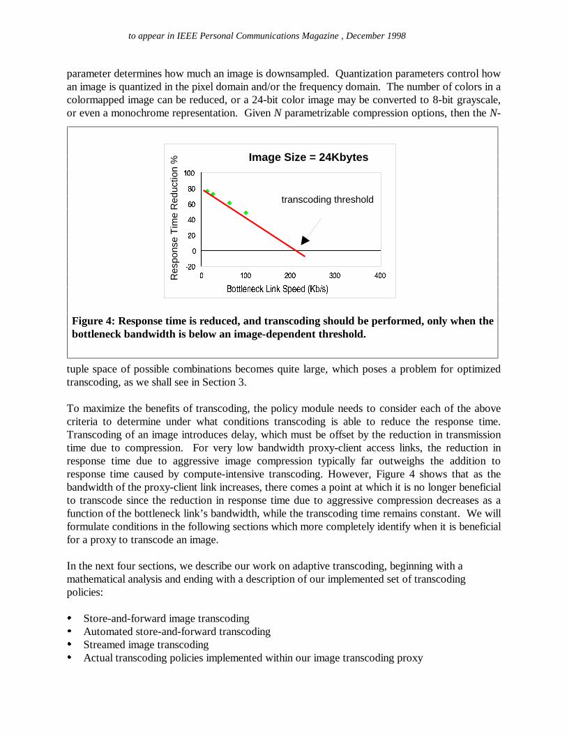
To maximize the benefits of transcoding, the policy module needs to consider each of the abovecriteria to determine under what conditions transcoding is able to reduce the response time.Transcoding of an image introduces delay, which must be offset by the reduction in transmissiontime due to compression. For very low bandwidth proxy-client access links, the reduction inresponse time due to aggressive image compression typically far outweighs the addition toresponse time caused by compute-intensive transcoding. However, Figure 4 shows that as thebandwidth of the proxy-client link increases, there comes a point at which it is no longer beneficialto transcode since the reduction in response time due to aggressive compression decreases as afunction of the bottleneck link’s bandwidth, while the transcoding time remains constant. We willformulate conditions in the following sections which more completely identify when it is beneficialfor a proxy to transcode an image.
In the next four sections, we describe our work on adaptive transcoding, beginning with amathematical analysis and ending with a description of our implemented set of transcodingpolicies:
> Store-and-forward image transcoding? Automated store-and-forward transcoding@ Streamed image transcodingA Actual transcoding policies implemented within our image transcoding proxy
Figure 4: Response time is reduced, and transcoding should be performed, only when thebottleneck bandwidth is below an image-dependent threshold.
B C B B D B B E B B F B BG H I I J K L K M N4O P L N�Q6R K K SUT V6W X Y Z
[ D BBD BF B\ B] BC B B
Res
pons
e T
ime
Red
uctio
n % Image Size = 24Kbytes
transcoding threshold

to appear in IEEE Personal Communications Magazine , December 1998
^�_a`cb�d�egf4h igj�k�fml�n6j�o d�p�b�o qgl�n r�d�n6b�s tud�v�j�wxn6d�p�y{z�l�b�h p�v
In this section, we develop an analytical framework determining when it is beneficial to transcodefor a class of proxies that store and forward images. We define a store-and-forward imagetranscoder as an image transcoder which must wait to accumulate an entire input image beforetranscoding can begin on this image and then must wait to generate a transcoded image in itsentirety before it is made available to be output, i.e. the input image cannot be read partially norcan the output image be written partially by the transcoder. Typical command-line interfaces toimage conversion libraries are store-and-forward transcoders that require the input image in itsentirety before image processing can commence, and internally generate a transcoded image in itsentirety before making it available as output.
Consider the analytical model of the system shown in Figure 5. The original image of size S(bytes) is downloaded into the store-and-forward proxy over the server-proxy connection witheffective bandwidth Bsp (bits/sec). The transcoder introduces a delay Dp(S) and generates anoutput image of size Sp(S). Both the transcoding delay and output image’s byte size are denotedto be dependent upon the input image’s byte size S, though in fact they are dependent upon manyother factors, including the image’s content, its dimensions, the set of transcoding parametersapplied, the compression algorithms used, the efficiency of the algorithm’s implementation, andthe desired user preferences (quality and response time). The transcoded image is thentransmitted over a proxy-client connection having effective bandwidth Bpc.
2.1 To transcode or not to transcode
Suppose Ro is the response time of fetching a Web object of byte size S from the Web server withtranscoding turned off. Similarly, let Rp denote the response time of fetching the transcodedversion of the same Web object through the transcoding proxy. For the purpose of the followingdiscussion we assume that caching is not supported at the proxy.
Figure 5: Model of store-and-forward image transcoding proxy.
Image Transcoding
Proxy
Web client
Image size S (in bytes)
Bandwidth Bsp
Image size Sp(S)
Bandwidth Bpc
Transcoding Delay Dp(S)
Web server

to appear in IEEE Personal Communications Magazine , December 1998
The client perceived response time with transcoding turned off is the sum of the following threeterms:
Ro = 2 | RTTpc + 2 } RTTsp ~ + Smin(Bpc,Bsp) (1)
RTTpc is the network roundtrip time latency between the client and the proxy and, similarly, RTTsp
is the latency between the proxy and the server. Fetching the Web object requires a TCPSYN/ACK exchange as well as an HTTP request/response, thereby contributing2 � RTTpc + 2 � RTTsp to the delay term. In addition, a Web image incurs a transmission delay equalto the spread in time between arrival of its first and last bits. Let min(Bpc,Bsp) denote thebottleneck bandwidth between the client and the server. In the absence of a proxy, the first and
last bits of an image will be spread in time by S
min(Bpc,Bsp) . This spread corresponds to the effectivetransmission time of the image over the concatenated server-to-proxy-to-client connection.
When transcoding is turned on, the proxy operates in a store and forward mode.2 � RTTpc + 2 � RTTsp is again the fixed component of the response time. Dp(S) is the additionalterm that represents the transcoding delay. The object download time is the sum of the transfertime over the server-proxy link and the proxy-client link. The exact relationship can be expressedas:
Rp = 2 � RTTpc + 2 � RTTsp � +Dp(S) + SBsp
+Sp(S)Bpc (2)
Transcoding will reduce response time if Rp < Ro. That is,
Dp(S) + SBsp
+Sp(S)Bpc
< Smin(Bpc,Bsp) (3)
The above inequality precisely characterizes the regime for which transcoding reduces responsetime. We can also use the same inequality to define an objective policy for making transcodingdecisions. The proxy can then use this policy to decide on an image-by-image basis whethertranscoding should be applied or not. Except for S, the byte size of the original image, which canbe determined from the content-length header of HTTP response message, the rest of theparameters in the above inequality need to be estimated.
Clearly, when Bpc > Bsp, it is always the case that Rp > Ro. Thus, when the Internet backbone’sserver-proxy connection is the bottleneck, then a store-and-forward image transcoder shouldnever transcode.
The more typical case occurs when the proxy-client access link is the bottleneck, i.e. whenBpc < Bsp. In this case, transcoding is useful if and only if

to appear in IEEE Personal Communications Magazine , December 1998
Dp(S) + SBsp
<S−Sp(S)
Bpc (4)
2.2 Prediction of the transcoded image’s output size in bytes
In order to determine whether response time can be decreased by transcoding, we need to be ableto predict the transcoded image’s byte size Sp(S) in Inequality 3. The output byte size depends ona variety of factors, including the content of the image (i.e. whether it is a natural image, or anartificially rendered text/graphic image), the image dimensions, the input byte size S, the outputcompression format, the transcoding parameters (e.g. depth of quantization and/or scaling), andthe implementation efficiency of the compression algorithm.
Prediction must be performed in advance of transcoding. This requires that we infer as muchinformation as possible from such sources as the image header and prior image statistics. Theimage header typically provides the input byte size S and image dimensions. In addition, weassume that the transcoding parameters and output compression format are chosen in advance andgiven to the output byte size prediction module. Images that share the same input byte size S anddimensions, and that are transcoded with the same parameters to the same output format, willnevertheless exhibit a variation in transcoded output byte size due to inherent variation of imagecontent across images. Consequently, output byte size prediction requires an analysis of thestatistical distribution of output sizes for previously transcoded images. Extracting correlationpatterns between output byte size and the various input parameters is the objective of the rest ofthis section.
In the following, we confine our analysis of output byte size prediction to transcoding of colorGIF and color JPEG images to the grayscale JPEG output format. We do not analyze imagetranscoding to the GIF output format in this paper. Also, we consider only the influence of theJPEG quality factor q on the output byte size. The JPEG quality factor q ranges from 0 to 100, asdefined in the Independent JPEG group’s code [7], where high quality values correspond to lowcompression, while low quality values correspond to aggressive compression. Though scaling isanother useful transcoding parameter for compression, we do not consider its influence on outputbyte size here.
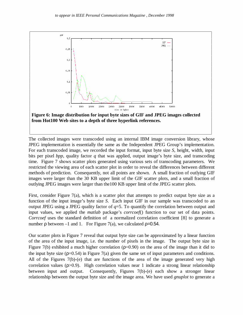
We collected images from the Hot100.com list of most visited Web sites, to a recursive searchdepth of three levels. In Figure 6, we illustrate the probability distribution of the collected inputimages as a function of their input byte size. The collected set of images consists of 2616 GIFimages, and 108 JPEG images. The bias towards GIF images is presumably because most Websites (e.g. CNN.com) are filled with artificially-rendered advertisements, logos, and navigationbars that compress well under GIF, rather than natural images that compress well using JPEG.The average byte size of a GIF was 3.6 KB, and the average byte size of a JPEG was 10.9 KB.
to appear in IEEE Personal Communications Magazine , December 1998
The collected images were transcoded using an internal IBM image conversion library, whoseJPEG implementation is essentially the same as the Independent JPEG Group’s implementation.For each transcoded image, we recorded the input format, input byte size S, height, width, inputbits per pixel bpp, quality factor q that was applied, output image’s byte size, and transcodingtime. Figure 7 shows scatter plots generated using various sets of transcoding parameters. Werestricted the viewing area of each scatter plot in order to reveal the differences between differentmethods of prediction. Consequently, not all points are shown. A small fraction of outlying GIFimages were larger than the 30 KB upper limit of the GIF scatter plots, and a small fraction ofoutlying JPEG images were larger than the100 KB upper limit of the JPEG scatter plots.
First, consider Figure 7(a), which is a scatter plot that attempts to predict output byte size as afunction of the input image’s byte size S. Each input GIF in our sample was transcoded to anoutput JPEG using a JPEG quality factor of q=5. To quantify the correlation between output andinput values, we applied the matlab package’s corrcoef() function to our set of data points.Corrcoef uses the standard definition of a normalized correlation coefficient [8] to generate anumber ρ between –1 and 1. For Figure 7(a), we calculated ρ=0.54.
Our scatter plots in Figure 7 reveal that output byte size can be approximated by a linear functionof the area of the input image, i.e. the number of pixels in the image. The output byte size inFigure 7(b) exhibited a much higher correlation (ρ=0.90) on the area of the image than it did tothe input byte size (ρ=0.54) in Figure 7(a) given the same set of input parameters and conditions.All of the Figures 7(b)-(e) that are functions of the area of the image generated very highcorrelation values (ρ>0.9). High correlation values near 1 indicate a strong linear relationshipbetween input and output. Consequently, Figures 7(b)-(e) each show a stronger linearrelationship between the output byte size and the image area. We have used gnuplot to generate a
Figure 6: Image distribution for input byte sizes of GIF and JPEG images collectedfrom Hot100 Web sites to a depth of three hyperlink references.
to appear in IEEE Personal Communications Magazine , December 1998
lines that have been curve-fitted to these sets of data points to emphasize the approximately linearrelationship between output and input.
The strong linear correlation between the number of output bytes and the area in Figure 7(b)explains the relative lack of correlation between the output byte size and the input byte size inFigure 7(a). A large-dimension image and a small-dimension image may share the same input bytesize S, yet produce vastly different output byte sizes based on the linear prediction obtained fromFigure 7(b). This results in a wide spread around each value S and lower correlation in Figure7(a). A topic of ongoing research is trying to explain the general linear dependency of the numberof output bytes on the image area, which seems to be independent of input format and qualityfactor.
We have several final remarks on our data. The JPEG scatter plots had many fewer images thanthe GIF input plots due to the skew of the Hot100 sites towards GIF encoding. Also, we notethat several vertical lines appear in Figure 7(b). These are due to a concentration of images in ourcollected sample which all share the same input area. It is a possible that a standard byte size orset of dimensions exist on the Web that would cause this phenomenon, though we haven’t yetverified this. Finally, it appears at first glance in Figure 7(b) that zero input pixels fail to producezero output bytes, as one would normally expect. In fact, a small input GIF (whose header takesabout 120 bytes for a 32-color image) may occupy less than 200 bytes total and appear to be azero input given that the scale of the x-axis is in thousands of bytes. In addition, a typical JPEGgrayscale header incurs about 300 bytes in overhead due to quantization and Huffman tabledefinitions. Given the different scales of the x and y axes, a small JPEG generated from a smallinput GIF may appear to cause a sudden jump to hundreds of output bytes starting from a smallernumber of input bytes that look deceptively close to zero.

to appear in IEEE Personal Communications Magazine , December 1998
(a) O=f(bytes), GIF input, q=5, ρ=0.54 (b) O=f(pixels), GIF input, q=5, ρ=0.90
(c) O=f(pixels), GIF input, q=50, ρ=0.91 (d) O=f(pixels), JPEG input, q=5, ρ=0.94
(e) O=f(pixels), JPEG input, q=50, ρ=0.92
Figure 7: Prediction of the output size O (in bytes) of a transcoded image.

to appear in IEEE Personal Communications Magazine , December 1998
2.3 Prediction of the transcoding delay
In order to evaluate Inequality 3, we also need to be able to accurately predict the transcodingdelay Dp(S) of each image. The transcoding time is more difficult to predict than the output bytesize because Dp(S) depends not only on image processing time, but also on queuing delay causedby the operating system’s sharing of the CPU among multiple processes and threads. The variabledelay introduced by the operating system is especially difficult to predict in non-real-timeoperating systems.
Suppose we desire only to predict the time due to image processing. Dp(S) will depend upon thespeed of the processor, and the implementation efficiency of both decoders and encoders in theimage conversion library, in addition to the factors from Section 2.2 that influenced the outputbyte size, namely the content of the image, the image dimensions, the input byte size S, the outputformat, and the transcoding parameters. Similar to the case of output byte size prediction,transcoding time prediction will require an analysis of the statistical distribution of previouslytranscoded images, so that correlation patterns between output delay and input parameters can beextracted.
We assume the same conditions for transcoding as the previous section. In addition, thetranscoding time measurements of this section were performed on an internal IBM imageconversion library on a 200 MHz Pentium Pro running NT 4.0.
Our scatter plots in Figure 8 reveal that transcoding time can also be approximated by a linearfunction of the area of the input image. We hypothesize that Figure 8(d)’s linear dependency isdue to the fact that the largest component of time in JPEG encoding and decoding is the DCT.The number of DCT’s invoked per image is a direct linear function of the number of blocks, hencethe area, of the image. Thus, for JPEG-to-JPEG conversions, there should be a strong linearrelationship between transcoding time and area. Figure 8(d) (ρ=0.98) and Figure 8(e) (ρ=0.98)exhibit this strong linear relationship for different values of q. For GIF-to-JPEG conversions, wewould expect GIF decoding times to be highly image-dependent, so that the overall transcodingtime would exhibit less linear correlation than the JPEG-to-JPEG cases. In fact, the correlationvalues of Figure 8(b) (ρ=0.82) and Figure 8(c) (ρ=0.60) are both lower than their JPEG-to-JPEGcounterparts at the same value q. This hypothesis would also explain the relative lack of linearcorrelation between the transcoding time and the input byte size in Figure 8(a). The linearcorrelation between area and output transcoding delay in Figure 8(b) would predict that large andsmall images sharing similar input byte sizes will have a wide spread in transcoding times.

to appear in IEEE Personal Communications Magazine , December 1998
(a) T=f(bytes), GIF input, q=5, ρ=0.65 (b) T=f(pixels), GIF input, q=5, ρ=0.82
(c) T=f(pixels), GIF input, q=50, ρ=0.60 (d) T=f(pixels), JPEG input, q=5, ρ=0.98
(e) T=f(pixels), JPEG input, q=50, ρ=0.98
Figure 8: Prediction of the image transcoding time T (in ms) for a transcoded image.

to appear in IEEE Personal Communications Magazine , December 1998
2.4 Connection monitoring and download time estimation
The automated policy decisions depend to a large extent on the accuracy of image download timeestimates. To evaluate Inequality 3, we require accurate estimation of the download time of imageobjects, as represented by the terms Sp(S)/Bpc and S/Bsp. Our method of performance predictioninvolves monitoring the ongoing connections and estimating image download times by performingstatistical analysis on the collected traces. These functions are split into two modules: viz.,Connection Monitor and Statistical Analyzer. The connection monitor is a transparent shim layer(a winsock style dll on windows platform) which is inserted between the application and thesocket layer. It records every send and receive event at the proxy. Whenever an application (e.g.,Web browser, or proxy server) makes a socket layer call, a stub routine inside the shim layer isexecuted, which, after creating a log entry, passes control to the requested function inside thesocket layer. The overhead of monitoring is minimized by keeping the code path through theshim layer short and moving all computation to the statistical analyzer module. For eachmonitored connection we record the following information:
� time when a new connection is established� source address, source port number & destination address, destination port number of eachnetwork connection� number of bytes sent and received on each connection and the respective timestamp of everysend and receive event� time when connections are closed
The statistical analyzer maintains a database of all past and all current active connections. Basedon the history of collected samples the statistical analyzer is able to make predictions about thedownload time of image objects. This approach is similar to the passive monitoring method, calledSPAND that was originally proposed in [9]. In fact, SPAND’s monitor and statistical analyzer canalternatively be used in conjunction with our proxy. The modular architecture of the proxy allowsus to flexibly place the monitor and analyzer function anywhere in the network, though co-locating the two functions at the proxy minimizes the overhead of communication between them.
For predicting the server-to-proxy download time and the proxy-to-client download time we usedifferent heuristics. From server to proxy traces we estimate the download time, rather than thebandwidth directly. This is because throughput of small sized wide-area TCP connections istypically a non-liner function of object sizes. The non-linear behavior is clearly visible in Figure 9,which is a typical example of a sequence number vs. time plot for a set of http connections to afixed Web server1. To predict the download time of an object of a given size, we look at thehistory of connections to the chosen destination and compute the distribution function of thedownload time for all objects that have roughly the same size. The median, or some otherappropriate statistical function of this distribution, is returned as the download time estimate.
In contrast, proxy-to-client TCP behavior is dominated by the effects of having a bandwidthconstrained link, which is typically the last hop. Because there is a bottleneck link, the aggregateof all active TCP connections to a client typically saturate the bottleneck link. Thus, for providing 1 Based on wide area TCP traces provided to us by Srinivasan Seshan.

to appear in IEEE Personal Communications Magazine , December 1998
proxy-to-client download time estimates, we aggregate all active connections to a client into asingle group. For each group of connections we plot a time vs. number of bytes plot and thenperform a linear curve-fit on the data. This gives us a reasonably accurate estimate of the currentavailable bandwidth between the proxy and the client. Although this value changes with time, theoscillations in most cases are bounded. For example, we can easily detect whether we areconnected by a 14.4 Kb modem, 28.8 Kb modem, or 56 Kb modem by looking at the output ofour curve fitting algorithm. The predicted values are not exact (20 - 30% deviation from thecorrect values), but we expect the policy decisions based on these estimates to outperform anyadaptation methods solely dependent on user selected preferences.
���a� ���m���u���m�������m���6��� � ����� �g��� �����6��� �u�������x�6�����{������� ���
Two classes of transcoding policies that incorporate the test condition of Inequality 3, namelyfixed-quality and fixed-delay (automated) adaptation, are discussed in this section. The distinctionbetween the two classes is based on whether the user preference index value fed back by the slidebar in Figure 3 is interpreted as a quality specification or as an upper bound on tolerable delay.
The simplest case results from interpreting the slide bar’s index value as a fixed-qualityspecification. In this scenario, the user is manually choosing the set of transcoding parameterswith which to transcode an image. A fixed-quality store-and-forward transcoder would evaluateInequality 3 exactly once using the prespecified vector of parameters, which affect the prediction
Figure 9: TCP sequence numbers vs. time for several connections to a destination.
to appear in IEEE Personal Communications Magazine , December 1998
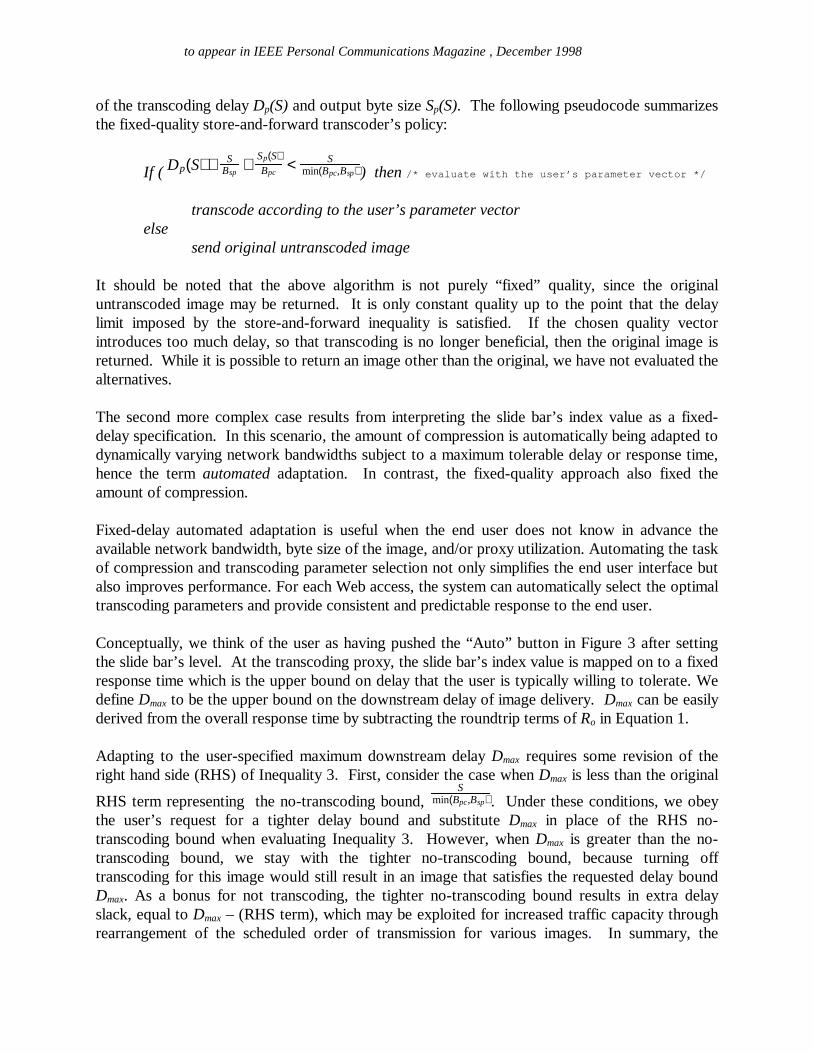
of the transcoding delay Dp(S) and output byte size Sp(S). The following pseudocode summarizesthe fixed-quality store-and-forward transcoder’s policy:
If ( Dp(S) + SBsp
+Sp(S)Bpc
< Smin(Bpc,Bsp) ) then / * eval uat e wi t h t he user ’ s par amet er vect or * /
transcode according to the user’s parameter vectorelse
send original untranscoded image
It should be noted that the above algorithm is not purely “fixed” quality, since the originaluntranscoded image may be returned. It is only constant quality up to the point that the delaylimit imposed by the store-and-forward inequality is satisfied. If the chosen quality vectorintroduces too much delay, so that transcoding is no longer beneficial, then the original image isreturned. While it is possible to return an image other than the original, we have not evaluated thealternatives.
The second more complex case results from interpreting the slide bar’s index value as a fixed-delay specification. In this scenario, the amount of compression is automatically being adapted todynamically varying network bandwidths subject to a maximum tolerable delay or response time,hence the term automated adaptation. In contrast, the fixed-quality approach also fixed theamount of compression.
Fixed-delay automated adaptation is useful when the end user does not know in advance theavailable network bandwidth, byte size of the image, and/or proxy utilization. Automating the taskof compression and transcoding parameter selection not only simplifies the end user interface butalso improves performance. For each Web access, the system can automatically select the optimaltranscoding parameters and provide consistent and predictable response to the end user.
Conceptually, we think of the user as having pushed the “Auto” button in Figure 3 after settingthe slide bar’s level. At the transcoding proxy, the slide bar’s index value is mapped on to a fixedresponse time which is the upper bound on delay that the user is typically willing to tolerate. Wedefine Dmax to be the upper bound on the downstream delay of image delivery. Dmax can be easilyderived from the overall response time by subtracting the roundtrip terms of Ro in Equation 1.
Adapting to the user-specified maximum downstream delay Dmax requires some revision of theright hand side (RHS) of Inequality 3. First, consider the case when Dmax is less than the original
RHS term representing the no-transcoding bound, S
min(Bpc,Bsp) . Under these conditions, we obeythe user’s request for a tighter delay bound and substitute Dmax in place of the RHS no-transcoding bound when evaluating Inequality 3. However, when Dmax is greater than the no-transcoding bound, we stay with the tighter no-transcoding bound, because turning offtranscoding for this image would still result in an image that satisfies the requested delay boundDmax. As a bonus for not transcoding, the tighter no-transcoding bound results in extra delayslack, equal to Dmax – (RHS term), which may be exploited for increased traffic capacity throughrearrangement of the scheduled order of transmission for various images. In summary, the
to appear in IEEE Personal Communications Magazine , December 1998
transcoding proxy replaces the RHS term S
min(Bpc,Bsp) of Inequality 3 with the expressionmin(Dmax,
Smin(Bpc,Bsp) ), i.e.
Dp(S) + SBsp
+Sp(S)Bpc
< min(Dmax,S
min(Bpc,Bsp) ) (5)
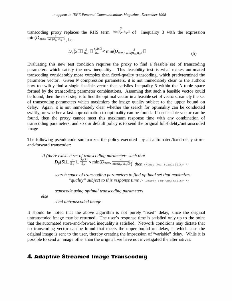
Evaluating this new test condition requires the proxy to find a feasible set of transcodingparameters which satisfy the new inequality. This feasibility test is what makes automatedtranscoding considerably more complex than fixed-quality transcoding, which predetermined theparameter vector. Given N compression parameters, it is not immediately clear to the authorshow to swiftly find a single feasible vector that satisfies Inequality 5 within the N-tuple spaceformed by the transcoding parameter combinations. Assuming that such a feasible vector couldbe found, then the next step is to find the optimal vector in a feasible set of vectors, namely the setof transcoding parameters which maximizes the image quality subject to the upper bound ondelay. Again, it is not immediately clear whether the search for optimality can be conductedswiftly, or whether a fast approximation to optimality can be found. If no feasible vector can befound, then the proxy cannot meet this maximum response time with any combination oftranscoding parameters, and so our default policy is to send the original full-fidelity/untranscodedimage.
The following pseudocode summarizes the policy executed by an automated/fixed-delay store-and-forward transcoder:
If (there exists a set of transcoding parameters such thatDp(S) + S
Bsp+
Sp(S)Bpc
< min(Dmax,S
min(Bpc,Bsp) )) then / * Test For Feasi bi l i t y * /
search space of transcoding parameters to find optimal set that maximizes“ quality” subject to this response time / * Sear ch For Opt i mal i t y * /
transcode using optimal transcoding parameterselse
send untranscoded image
It should be noted that the above algorithm is not purely “fixed” delay, since the originaluntranscoded image may be returned. The user’s response time is satisfied only up to the pointthat the automated store-and-forward inequality is satisfied. Network conditions may dictate thatno transcoding vector can be found that meets the upper bound on delay, in which case theoriginal image is sent to the user, thereby creating the impression of “variable” delay. While it ispossible to send an image other than the original, we have not investigated the alternatives.
�¡a¢c£�¤�¥g¦4§ ¨g©�ª�¦4«6©�¤�¬u©�£� ¬u¤�®�©�¯x«6¤�°�±{²�³�£�§ °�®
to appear in IEEE Personal Communications Magazine , December 1998
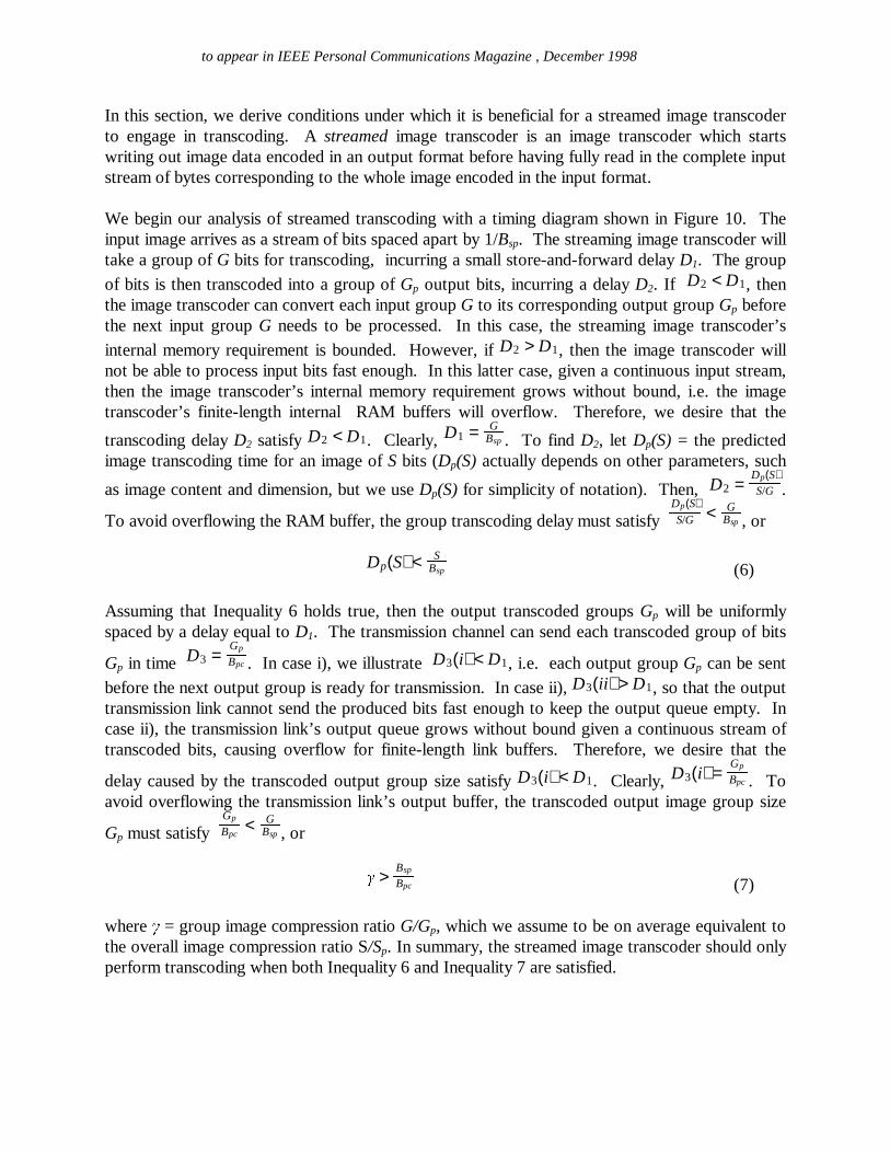
In this section, we derive conditions under which it is beneficial for a streamed image transcoderto engage in transcoding. A streamed image transcoder is an image transcoder which startswriting out image data encoded in an output format before having fully read in the complete inputstream of bytes corresponding to the whole image encoded in the input format.
We begin our analysis of streamed transcoding with a timing diagram shown in Figure 10. Theinput image arrives as a stream of bits spaced apart by 1/Bsp. The streaming image transcoder willtake a group of G bits for transcoding, incurring a small store-and-forward delay D1. The group
of bits is then transcoded into a group of Gp output bits, incurring a delay D2. If D2 < D1, thenthe image transcoder can convert each input group G to its corresponding output group Gp beforethe next input group G needs to be processed. In this case, the streaming image transcoder’s
internal memory requirement is bounded. However, if D2 > D1, then the image transcoder willnot be able to process input bits fast enough. In this latter case, given a continuous input stream,then the image transcoder’s internal memory requirement grows without bound, i.e. the imagetranscoder’s finite-length internal RAM buffers will overflow. Therefore, we desire that the
transcoding delay D2 satisfy D2 < D1. Clearly, D1 = GBsp . To find D2, let Dp(S) = the predicted
image transcoding time for an image of S bits (Dp(S) actually depends on other parameters, such
as image content and dimension, but we use Dp(S) for simplicity of notation). Then, D2 =Dp(S)S/G .
To avoid overflowing the RAM buffer, the group transcoding delay must satisfy Dp(S)S/G < G
Bsp , or
Dp(S) < SBsp (6)
Assuming that Inequality 6 holds true, then the output transcoded groups Gp will be uniformlyspaced by a delay equal to D1. The transmission channel can send each transcoded group of bits
Gp in time D3 =Gp
Bpc . In case i), we illustrate D3(i) < D1, i.e. each output group Gp can be sent
before the next output group is ready for transmission. In case ii), D3(ii) > D1, so that the outputtransmission link cannot send the produced bits fast enough to keep the output queue empty. Incase ii), the transmission link’s output queue grows without bound given a continuous stream oftranscoded bits, causing overflow for finite-length link buffers. Therefore, we desire that the
delay caused by the transcoded output group size satisfy D3(i) < D1. Clearly, D3(i) =Gp
Bpc . Toavoid overflowing the transmission link’s output buffer, the transcoded output image group size
Gp must satisfy Gp
Bpc< G
Bsp , or
´ > Bsp
Bpc (7)
where µ = group image compression ratio G/Gp, which we assume to be on average equivalent tothe overall image compression ratio S/Sp. In summary, the streamed image transcoder should onlyperform transcoding when both Inequality 6 and Inequality 7 are satisfied.

to appear in IEEE Personal Communications Magazine , December 1998
If the server-proxy link is the bottleneck, i.e. Bsp < Bpc, then Inequality 7 reduces to ¶ > N, whereN is a number less than 1. Normally, the compression ratio is always greater than 1, so Inequality7 will always be satisfied. In this case, only Inequality 6 must be satisfied in order for transcodingto not be disadvantageous. In fact, when the server-proxy link is the bottleneck, Inequality 7could be interpreted as providing an upper bound on the ratio of expansion allowed for a
transcoded image, namely 1· < Bpc
Bsp . Expansion of an image may occasionally be necessary whenformat conversion is mandatory, e.g. GIF->2-bit grayscale (Palm PDA format). The aboveinequality allows us to determine when such a format conversion will increase the chances ofbuffer overflow, and when format conversion will not cause buffer overflow. For example, if wehave Bsp = 1 bps, Bpc = 2 bps, and G = 1 bit, then Inequality 7 says that the output group Gp canexpand to a maximum of 2 bits.
If the proxy-client link is the bottleneck, i.e. Bsp > Bpc, then Inequality 7 says that the imagecompression ratio ¸ must be greater than the ratio of server-proxy to proxy-client bandwidths inorder for transcoding to be worthwhile. In addition, Inequality 6 must also be satisfied.
G
Transcoded Output GroupsAre Uniformly Spaced
Time
Time
Time
Timei)
ii)
Input Bit Stream
D1
D2D
3(i)
D3(ii)
Gp
1/Bsp
1/Bpc
Gp
Figure 10: Timing diagram for streamed image transcoding.

to appear in IEEE Personal Communications Magazine , December 1998
Note that Inequality 6 and Inequality 7 are tight bounds that assume that the buffer must never beallowed to overflow. Looser constraints may be derived given that images are of finite-length,rather than the continuous stream assumed in the analysis. More relaxed constraints would permitmore time for transcoding and/or allow less aggressive compression.
¹�º�»#¼�½�¾�¿�À ¾�½�Á�»�Â�Á À ¾�À Ã�ÄÆÅ�Â�¼x½�Ç�È É�½�Ê�Ã�Ë�¼�½�Ç�Ä!¾�Â�Ì�À Ç�Ê�»#¼�Â�Í�Î
In previous sections, we developed an analytical framework for determining the conditions underwhich it is beneficial to transcode for store-and-forward as well as streaming proxies. In thissection, we discuss the set of practical transcoding policies that we have implemented in ourstore-and-forward transcoding proxy. These policies were developed incrementally by feedingback the lessons we learned throughout the development and evaluation of our transcoding proxy.The implemented policies adapt the transcoding to the client’s device type, user qualitypreferences, and image content, but do not currently adapt to network bandwidth, and do notcurrently perform prediction of the image transcoding delay and output byte size.
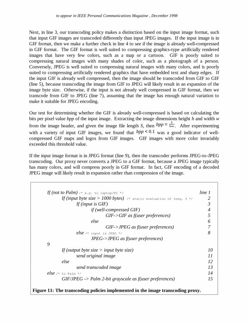
Our current set of transcoding policies is summarized in pseudocode in Figure 11. Ourtranscoding proxy first makes a distinction in line 1 between transcoding to a laptop andtranscoding to a Palm Pilot PDA. Unless otherwise notified, the proxy assumes that it istranscoding to a PC laptop, namely a client device that supports GIF and JPEG decoding.
Given a PC/laptop, the proxy next checks in line 2 to see if the image is sufficiently large fortranscoding. Images smaller than a threshold of 1000 bytes are deemed to be not worth thesavings in download time brought about by compression and hence are not transcoded. Thisthreshold is obtained by applying Inequality 3’s test condition, except that we assume that Bpc and
Bsp are fixed, and that the common case is where Bpc < Bsp. Rearranging terms in Inequality 3, wefind that the input byte size must satisfy the following in order for transcoding to be worthwhile:
S>Dp(S)+
Sp(S)Bpc
1Bpc − 1
Bsp (8)Let Bpc = 50 kbit/s, Bsp = 1 Mbit/s. For small images of input length about 500 bytes, we havemeasured average transcoding times of approximately 40 ms through our transcoding routines.We assume that it is typically hard to squeeze significant compression out of small images, say nomore than 2 to 1, so that input and output sizes are closely related, and that the transcoding timedoes not vary much within this small range. Consequently, producing Sp(S) = 500 output bytesstarting from a small image will take about Dp(Sp(S)) = 40 ms of processing delay. Substitutingvalues, Inequality 8 shows that the input byte size S must exceed about 800 bytes in order fortranscoding to reduce response time, hence our threshold of 1000 bytes.
to appear in IEEE Personal Communications Magazine , December 1998
Next, in line 3, our transcoding policy makes a distinction based on the input image format, suchthat input GIF images are transcoded differently than input JPEG images. If the input image is inGIF format, then we make a further check in line 4 to see if the image is already well-compressedin GIF format. The GIF format is well suited to compressing graphics-type artificially renderedimages that have very few colors, such as a map or a cartoon. GIF is poorly suited tocompressing natural images with many shades of color, such as a photograph of a person.Conversely, JPEG is well suited to compressing natural images with many colors, and is poorlysuited to compressing artificially rendered graphics that have embedded text and sharp edges. Ifthe input GIF is already well compressed, then the image should be transcoded from GIF to GIF(line 5), because transcoding the image from GIF to JPEG will likely result in an expansion of theimage byte size. Otherwise, if the input is not already well compressed in GIF format, then wetranscode from GIF to JPEG (line 7), assuming that the image has enough natural variation tomake it suitable for JPEG encoding.
Our test for determining whether the GIF is already well-compressed is based on calculating thebits per pixel value bpp of the input image. Extracting the image dimensions height h and width w
from the image header, and given the image file length S, then bpp = Sh Ïw . After experimenting
with a variety of input GIF images, we found that bpp < 0.1 was a good indicator of well-compressed GIF maps and logos from GIF images. GIF images with more color invariablyexceeded this threshold value.
If the input image format is in JPEG format (line 9), then the transcoder performs JPEG-to-JPEGtranscoding. Our proxy never converts a JPEG to a GIF format, because a JPEG image typicallyhas many colors, and will compress poorly in GIF format. In fact, GIF encoding of a decodedJPEG image will likely result in expansion rather than compression of the image.
If (not to Palm) / * e. g. t o l apt op/ PC * / line 1If (input byte size > 1000 bytes) / * s t at i c eval uat i on of I neq. 3 * / 2
If (input is GIF) 3if (well-compressed GIF) 4
GIF->GIF as f(user preferences) 5else 6
GIF->JPEG as f(user preferences) 7else / * i nput i s JPEG * / 8
JPEG->JPEG as f(user preferences) 9
If (output byte size > input byte size) 10send original image 11
else 12send transcoded image 13
else / * t o Pal m * / 14GIF/JPEG -> Palm 2-bit grayscale as f(user preferences) 15
Figure 11: The transcoding policies implemented in the image transcoding proxy.
to appear in IEEE Personal Communications Magazine , December 1998
In lines 5, 7, and 9, once the output format has been determined, the image is transcodedaccording to the user preferences (e.g. slide bar value) received from the user. The same sliderindex value can be mapped onto different transcoding vectors depending on the output format.Transcoding to GIF format limits us to scaling and colormap reduction to achieve compression.Transcoding to JPEG format allows us to specify quantization of frequency coefficients, as well asscaling. Occasionally, the choice of transcoding vector may actually result in expansion of theimage. In this case, we send the original image (line 11), rather than the transcoded image.
For the case of transcoding to the Palm PDA, we transcode GIF images and JPEG images to theoutput format, namely a 2-bit grayscale bitmap [10], applying a degree of compression that isagain a function of the user’s preference (line 15). The HTTP Palm client informs the HTTPtranscoding proxy that this is a Palm device by modifying the Accept field in the HTTP getrequest to say “image/palm”.
Ð�ÑgÒÔÓ�Õ�Ö�× Ø�ÙgÚ Ó�Õ
We presented an analytical framework describing when to transcode and when not transcode forstreaming and store-and-forward proxies under certain idealized assumptions. Transcoding isgenerally performed only when response time is reduced. While this idealized analysis providedinsight that we later incorporated into our actual adaptation policies, it had practical limitations,such as requiring accurate prediction of image transcoding times and image output sizes, as wellas accurate network bandwidth estimation of proxy-client and server-proxy links. We alsodescribed automated transcoding, a process by which the transcoding proxy adapts its imagecoding to network variability while trying to meet an upper bound on the delay tolerated by theend user. Automated adaptation requires a feasibility test to find transcoding vectors that satisfythe test for response time reduction, as well as an optimality search. Finally, we described ourexperience developing a practical set of policies that have been implemented within a transcodingHTTP proxy. These policies adapt to client heterogeneity, image content, and user preferences.These policies are largely motivated by the behavior of the GIF and JPEG image compressionalgorithms. They also incorporate a static evaluation of the store-and-forward test condition forreduced response time, thereby avoiding most of the test’s practical limitations.
ÛcÜ�Ý�Þ�ßgà�á â�ã�ä�â�åuâ�Þ�æmç
We wish to thank John R. Smith of IBM T.J. Watson for providing us with the set of images thathe collected from the Hot100 Web sites using his Web spider. We also wish to thank SrinivasaRao of IBM T.J. Watson for generating the matlab correlation statistics and for his proofreadinghelp.

to appear in IEEE Personal Communications Magazine , December 1998
è�é�êxë ì�í ë î�ï�ð6ñ�ò�ó!ô[1] A. Fox, E. Brewer, “Reducing WWW Latency and Bandwidth Requirements by Real-Time Distillation” , FifthInternational World Wide Web Conference, Computer Networks and ISDN Systems, vol. 28, no. 7-11, May 1996,pp. 1445-56.[2] A. Joshi, S. Weerawarana, and E. Houstis, ``On Disconnected Browsing of Distributed Information", Proc.IEEE RIDE ’97 , 1997, pp 101-107.[3] J. Smith; R. Mohan; C. Li, “Content-based Transcoding of Images in the Internet,” Proceedings of theInternational Conference on Image Processing (ICIP), 1998.[4] M. Nelson, J. Gailly, The Data Compression Book, Second Edition, M&T Books, 1996.[5] W. Pennebaker, J. Mitchell, JPEG Still Image Data Compression Standard, Chapman & Hall, 1993.[6] M. McIlhagga, A. Lightm and I. Wakeman, “Towards a Design Methodology for Adaptive Applications,”Proceedings of the International Conference on Mobile Computing and Networking (MobiCom), 1998.[7] http://www.ijg.org/.[8] A. Papoulis, Probability, Random Variables, and Stochastic Processes, third edition, McGraw Hill, 1991.[9] S. Seshan, M. Stemm, R. Katz, “SPAND: Shared Passive Network Performance Discovery,” Proc 1st UsenixSymposium on Internet Technologies and Systems (USITS '97) Monterey, CA, December 1997, pp. 135-46.[10] A. Fox, S. Gribble, Y. Chawathe, E. Brewer, “Adapting to Network and Client Variation Using InfrastructuralProxies: Lessons and Perspectives” , IEEE Personal Communications, vol. 5, no. 4, Aug. 1998, pp. 10-19.