ac 2007-447: verilog hdl controlled robot … hdl controlled robot for teaching complex systems...
TRANSCRIPT
AC 2007-447: VERILOG HDL CONTROLLED ROBOT FOR TEACHINGCOMPLEX SYSTEMS DESIGN
Austin Griffith, University of WyomingAustin Griffith completed the Bachelor of Science degree in Electrical Engineering in 2004 andthe Masters of Science degree in Electrical Engineering in 2006 at the University of Wyoming.He is a member of IEEE and Tau Beta Pi -- the Engineering Honor Society. He is projectengineer with Plasma Cam of Colorado City, Colorado.
Steven Barrett, University of WyomingSteven F. Barrett received the BS Electronic Engineering Technology from the University ofNebraska at Omaha in 1979, the M.E.E.E. from the University of Idaho at Moscow in 1986, andthe Ph.D. from The University of Texas at Austin in 1993. He was formally an active duty facultymember with the United States Air Force Academy, Colorado and is now an Associate Professorof Electrical and Computer Engineering, University of Wyoming. He is a member of IEEE(senior) and Tau Beta Pi (chief faculty advisor). His research interests include digital and analogimage processing, computer-assisted laser surgery, and embedded controller systems. He is aregistered Professional Engineer in Wyoming and Colorado. He co-wrote with Dr. Daniel Pack“68HC12 Microprocessor: Theory and Application,” Prentice-Hall, 2002; “Embedded SystemsDesign and Applications with the 68HC12 and HS12,” Prentice-Hall, 2005; and “MicrocontrollerFundamentals for Engineers and Scientists,” Morgan-Claypool Publishers, 2006. In 2004, Barrettwas named “Wyoming Professor of the Year” by the Carnegie Foundation for the Advancementof Teaching. Email: [email protected]
Daniel Pack, U.S. Air Force AcademyDaniel J. Pack is a Professor in the Department of Electrical Engineering at the United States AirForce Academy, CO. He received the Bachelor of Science degree in Electrical Engineering in1988, the Master of Science degree in Engineering Sciences in 1990, and the Ph.D. degree inElectrical Engineering in 1995 from Arizona State University, Harvard University, and PurdueUniversity, respectively. He was a visiting scholar at Massachusetts Institute ofTechnology-Lincoln Laboratory. He co-authored two textbooks on microcontrollers andembedded systems and authored over 70 journal and conference papers. He is a member of EtaKappa Nu, Tau Beta Pi (faculty advisor), IEEE (senior), and ASEE. He is a registeredProfessional Engineer in Colorado. In 2005, Pack was named “Colorado Professor of the Year”by the Carnegie Foundation for the Advancement of Teaching. His research interests includecooperative UAVs, intelligent control, automatic target recognition, and robotics. Email:[email protected]
© American Society for Engineering Education, 2007
Verilog HDL Controlled Robot
For Teaching Complex Systems Design
Abstract
Verilog Hardware Descriptive Language (HDL) design tools are a valuable tool for the
digital systems designer. Many undergraduate programs in electrical and computer engineering and computer science provide basic and advanced coursework on this topic. In an effort to provide a motivating (fun) atmosphere to teach HDL, we have developed an autonomous maze navigating robot. This robot was originally developed for use in a microcontroller-based Real Time Embedded Systems course to teach complex concepts such as Real Time Operating Systems (RTOS) and also fuzzy logic control. We have equipped the robot with an off-the-shelf CPLD development board. In this paper we will discuss the design of the robot modifications, the laboratory assignments to support use of the robot in a senior level, advanced digital design course, and the results of using the robot in the classroom. We will also discuss the valuable lessons learned by students in comparing a Verilog HDL system solution versus a microcontroller based solution to the same design challenge.
Overview
Verilog HDL techniques are a valuable tool for the digital systems designer. Many departments of electrical engineering, computer engineering, and computer science offer fundamental and advanced coursework in the state-of-the-art digital design technique. At our university we use Verilog HDL design concepts in our first digital design course as well as an advanced course devoted to digital system design. The advanced system design course is three semester hours and meets for three 50 minute lectures per week. During the course of the semester students practice theory of HDL learned in the lectures through ten different homework assignments. The homework assignments are completed using the Xilinx Project Navigator. Students must demonstrate the proper execution of their design using the ModelSim XE Simulator. Proper test procedures and test bench development are emphasized throughout the course. Students are required to develop a test bench for each homework exercise.
The course culminates in a team design project. The purpose of the project is for students to choose a project of moderate difficulty involving the interaction of several systems. The students work in teams of two. Once they select a project, they then perform a background investigation of the project, determine a list of project requirements, design the project, and develop a testbench to demonstrate the proper operation of the project. Students provide a ten minute oral summary of the project to the class and also provide a ten page written report. The
report contains a project abstract, requirements, design, testing, and results. In the Fall 2006 offering of the course, the following final projects were completed:
• Contra Code Relay Switch • Eight Character Marquee Display
• Arithmetic Logic Unit • Autonomous Robot Control
• Combinational Lock • 4-wire Stepper Motor Controller
• Frequency Counter • USB Controller
• Pulse Width Modulator • Four-channel Stepper Motor Controller
• Time Measurement of Robot Travel
• Digital Rate Multiplier
• Reconfigurable Johnson Counter • Cyclic Redundancy Check Generator
• Pipeline Processor • Floating Point Arithmetic Unit
• Encryption/Decryption • Garage Door Opener
• Random Number Generator with Linear Feedback Shift Registers
• Synchronous Communication System
In an effort to move the system design component earlier in the course and also provide
students the opportunity to take their designs to hardware, we investigated the use of a low cost Complex Programmable Logic Device (CPLD) board for use in the course. Our goal was to equip an educational robot with the CPLD board such that students could equip the robot with various subsystems. The overriding scenario was to have the robot navigate autonomously within an unknown maze. The robot was to proceed from a given start position within the maze to a designated stop position. Student teams would compete with one another to obtain the shortest maze traversal time while not bumping into maze walls.
We have used a maze-navigating robot in our advanced microcontroller systems design
course with great success [1]. The use of robots provide a high level of student excitement and buy-in while they learn complex digital system design concepts and techniques. Using robots as a motivational, educational tool in a laboratory environment is not a new idea. This idea has been used at many institutions [2, 3] with great success including Trinity College in Hartford, CT [4, 5]; the Massachusetts Institute of Technology [6], and the US Air Force Academy [7-9]. We have extended this idea to teach advanced Verilog HDL techniques, real time embedded system concepts, and the comparison of the two approaches.
In the following sections we provide background information on the project including information on Verilog HDL, our advanced Verilog HDL course, and observed difficulties students demonstrate in learning Verilog HDL design techniques. We then discuss methods employed for the project including the hardware and software developed and the laboratory exercises to guide the students in project development. We then provide results and a discussion of the results in placing the robots in the classroom. We conclude with future plans for this project.
Background
HDL devices consist of CPLDs or Field Programmable Gate Arrays (FPGAs). These devices consist of a “sea” of basic unconnected digital design components such as combinational

gates and flip-flops. The primary difference between the CPLD and the FPGA is the number of gates present within a given device. A sound design practice is to properly size a given digital design to the smallest capacity HDL. This provides for efficient and economical design implementation.
Hardware Descriptive Language (HDL) techniques allow a complex digital system to be designed in a programming-like environment. There are two primary types of software design tools: HDL software tools that look like the Ada programming language and Verilog HDL that has a “C” language appearing syntax. These programming environments are quite powerful and flexible. They allow the custom design of complex digital designs at a variety of abstraction levels. The software environment also allows the development of software testbenches to exhaustively test a design before it is actually synthesized in an HDL device. The actual synthesis step consists of downloading connection information between the “sea” of components on the HDL chip. The HDL process allows very complex digital designs to be completed in a timely manner. Many undergraduate programs in electrical and computer engineering and computer science provide basic and advanced coursework on this topic. Also some programs have used the HDL technique as a vehicle to teach advanced coursework in computer architecture. At our university we provide students their first exposure to HDL concepts in our sophomore level digital design course. In this course students complete a series of laboratory experiments of increasing difficulty. We also provide a senior elective course in Hardware Descriptive Language. Currently the course consists of a series of ten challenging but unrelated homework exercises. These ten exercises are summarized in Table 1.
Table 1. Current Homework Assignments
Homework
Assignment
Description
1
Skills review covering concepts from first digital design course
2 Introduction to Xilinx design tools
3 Six-bit ripple carry counter with set
4 Module construction, implementation alternatives
5 Test fixture development, primitives, modeling propagation delay
6 Gate level implementation
7 Synchronous counter design and test fixture development
8 Behavioral level implementation
9 Irrigation System Design, Development, Testing
10 Final Design Project
Students who take this course are senior-level and graduate students in electrical engineering, computer engineering, and computer science. The pre-requisite for this course is a first course in digital design. This mixed body of students provides a challenge to the instructor. For example, since a basic circuits course is not a pre-requisite for the course, some students may not have the necessary background to understand the basic electrical interfacing concepts such as voltage and current and capacitance concepts.

The course has been very successful in equipping students with solid HDL design skills. However, we wanted to improve the course by interjecting a series of related laboratory exercises to emphasize system development earlier in the course. Our ultimate goal is to provide a standalone laboratory session for this course.
Methods
In this section we briefly describe the hardware, software, and laboratory courseware to incorporate the use of robots in the senior-level HDL course. The Hardware
PROFBOT Robot. The PROFBOT robot prototype was developed with the goal of designing a low cost robot, using off-the-shelf components that would be easy to initially fabricate, maintain, and enjoy a long lifetime. We initially developed the robot for use in an advanced microcontroller-based embedded system design course. We expect to use this platform for digital design based projects for at least the next five years. Early attempts at developing a prototype included a completely in house design [10, 11]. However, the fabrication costs rendered this design cost prohibitive. We elected to use an off-the-shelf approach when a student-developed prototype proved to be a sound, low cost alternative to early in house attempts [12]. The prototype PROFBOT robot is illustrated in Figures 1 and 2 [1].
The design is a two-platform robot equipped with servo motor driven wheels. This basic platform configuration equipped with motors and wheels is available as a low cost (US $50) kit from Budget Robotics. The leading edge of the robot is equipped with four infrared emitter-detector pairs (Sharp GP2D12, US $12.95 each). Power is provided to the robot from one of two sources: 1) a rechargeable NiCad battery pack (Tower Hobbies, US $25 per battery pair) or a 2) 7.5 VDC, 1.1 A power supply (Jameco, US $10). The sensor and power subsystem are interfaced to the host microcontroller via an in house designed and produced printed circuit board (PCB). The cost to fabricate and populate the PCB is approximately US $30 per board [1].

Figure 1. PROFBOT Educational Robot equipped with a Digilent XCR Plus board. The board hosts a Xilinx CoolRunner XC3064CPLD [14].
Far LeftIR Sensor
Left IRSensor
Right IRSensor
Far RightIR Sensor
+-
Ba
tt1
+
Ba
tt2
+
Ba
tt1
-
Ba
tt2
-
PS
-
PS
+
BattSupply
PS
CenterOff
BOR
BOR
rightmotor
leftmotor
LM324op
amp
BYR
IR sensorinput block
FL
L SP
R FR
XilinxCoolRunner
XC3064CPLD
Figure 2. PROFBOT robot layout with Digilent XCR Plus board.
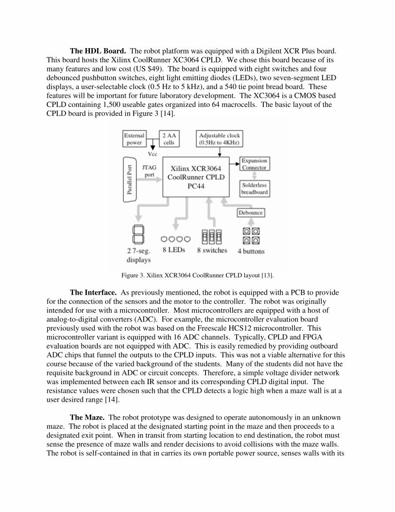
The HDL Board. The robot platform was equipped with a Digilent XCR Plus board. This board hosts the Xilinx CoolRunner XC3064 CPLD. We chose this board because of its many features and low cost (US $49). The board is equipped with eight switches and four debounced pushbutton switches, eight light emitting diodes (LEDs), two seven-segment LED displays, a user-selectable clock (0.5 Hz to 5 kHz), and a 540 tie point bread board. These features will be important for future laboratory development. The XC3064 is a CMOS based CPLD containing 1,500 useable gates organized into 64 macrocells. The basic layout of the CPLD board is provided in Figure 3 [14].
Figure 3. Xilinx XCR3064 CoolRunner CPLD layout [13].
The Interface. As previously mentioned, the robot is equipped with a PCB to provide for the connection of the sensors and the motor to the controller. The robot was originally intended for use with a microcontroller. Most microcontrollers are equipped with a host of analog-to-digital converters (ADC). For example, the microcontroller evaluation board previously used with the robot was based on the Freescale HCS12 microcontroller. This microcontroller variant is equipped with 16 ADC channels. Typically, CPLD and FPGA evaluation boards are not equipped with ADC. This is easily remedied by providing outboard ADC chips that funnel the outputs to the CPLD inputs. This was not a viable alternative for this course because of the varied background of the students. Many of the students did not have the requisite background in ADC or circuit concepts. Therefore, a simple voltage divider network was implemented between each IR sensor and its corresponding CPLD digital input. The resistance values were chosen such that the CPLD detects a logic high when a maze wall is at a user desired range [14].
The Maze. The robot prototype was designed to operate autonomously in an unknown maze. The robot is placed at the designated starting point in the maze and then proceeds to a designated exit point. When in transit from starting location to end destination, the robot must sense the presence of maze walls and render decisions to avoid collisions with the maze walls. The robot is self-contained in that in carries its own portable power source, senses walls with its
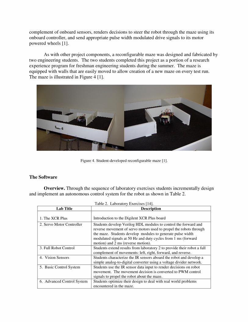
complement of onboard sensors, renders decisions to steer the robot through the maze using its onboard controller, and send appropriate pulse width modulated drive signals to its motor powered wheels [1].
As with other project components, a reconfigurable maze was designed and fabricated by two engineering students. The two students completed this project as a portion of a research experience program for freshman engineering students during the summer. The maze is equipped with walls that are easily moved to allow creation of a new maze on every test run. The maze is illustrated in Figure 4 [1].
Figure 4. Student-developed reconfigurable maze [1].
The Software
Overview. Through the sequence of laboratory exercises students incrementally design and implement an autonomous control system for the robot as shown in Table 2.
Table 2. Laboratory Exercises [14].
Lab Title Description
1. The XCR Plus
Introduction to the Digilent XCR Plus board
2. Servo Motor Controller Students develop Verilog HDL modules to control the forward and reverse movement of servo motors used to propel the robots through the maze. Students develop modules to generate pulse width modulated signals at 50 Hz and duty cycles from 1 ms (forward motion) and 2 ms (reverse motion).
3. Full Robot Control Students extend results from laboratory 2 to provide their robot a full complement of movements: left, right, forward, and reverse.
4. Vision Sensors Students characterize the IR sensors aboard the robot and develop a simple analog-to-digital converter using a voltage divider network.
5. Basic Control System Students use the IR sensor data input to render decisions on robot movement. The movement decision is converted to PWM control signals to propel the robot about the maze.
6. Advanced Control System Students optimize their design to deal with real world problems encountered in the maze.
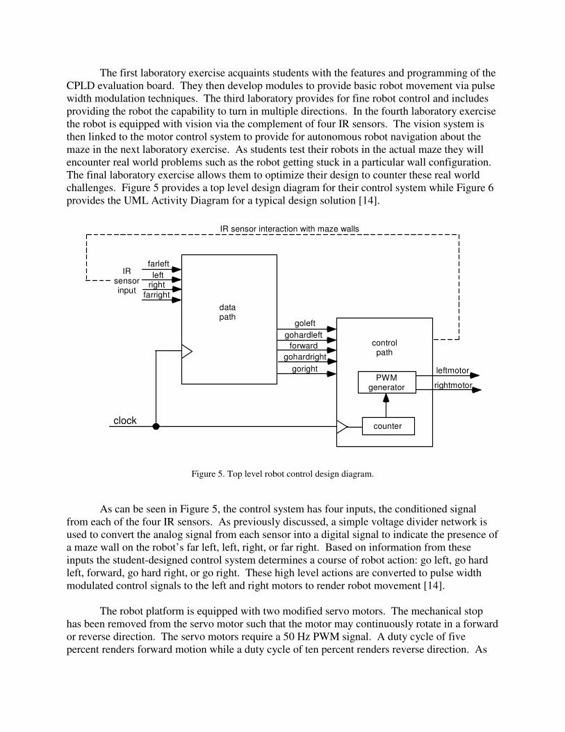
The first laboratory exercise acquaints students with the features and programming of the CPLD evaluation board. They then develop modules to provide basic robot movement via pulse width modulation techniques. The third laboratory provides for fine robot control and includes providing the robot the capability to turn in multiple directions. In the fourth laboratory exercise the robot is equipped with vision via the complement of four IR sensors. The vision system is then linked to the motor control system to provide for autonomous robot navigation about the maze in the next laboratory exercise. As students test their robots in the actual maze they will encounter real world problems such as the robot getting stuck in a particular wall configuration. The final laboratory exercise allows them to optimize their design to counter these real world challenges. Figure 5 provides a top level design diagram for their control system while Figure 6 provides the UML Activity Diagram for a typical design solution [14].
clock
farleft
leftright
farright
IRsensorinput
datapath
goleft
gohardleft
gohardright
goright leftmotor
rightmotorPWM
generator
controlpath
counter
IR sensor interaction with maze walls
forward
Figure 5. Top level robot control design diagram.
As can be seen in Figure 5, the control system has four inputs, the conditioned signal from each of the four IR sensors. As previously discussed, a simple voltage divider network is used to convert the analog signal from each sensor into a digital signal to indicate the presence of a maze wall on the robot’s far left, left, right, or far right. Based on information from these inputs the student-designed control system determines a course of robot action: go left, go hard left, forward, go hard right, or go right. These high level actions are converted to pulse width modulated control signals to the left and right motors to render robot movement [14]. The robot platform is equipped with two modified servo motors. The mechanical stop has been removed from the servo motor such that the motor may continuously rotate in a forward or reverse direction. The servo motors require a 50 Hz PWM signal. A duty cycle of five percent renders forward motion while a duty cycle of ten percent renders reverse direction. As

part of a laboratory exercise, students develop HDL modules to convert the high level desired robot action into low level PWM signals to render robot movement [1]. A 50 Hz signal may be derived from the CoolRunner CPLD’s onboard oscillator.
Figure 6. Typical robot control system design solution [14].

Results and Discussion
Adding a laboratory section to an existing course requires considerable financial resources. The HDL course currently enjoys an enrollment of approximately 50 students per offering. This would require the addition of four laboratory sections to support the course and the additional overhead of two teaching assistants. Since the robot platforms were already available from use in another course [1], the only additional hardware cost would be 25 of the Xilinx XCR3064 CoolRunner CPLD evaluation boards. Current department funding would not allow for the teaching assistant support or the evaluation boards at this time [14]. Instead we investigated lower-cost alternatives. Since this will be used in a senior/graduate level course, we felt we did not need the support of a teaching assistant to monitor the laboratory session. Senior and graduate level students have the requisite independence, knowledge, and sophisticated troubleshooting skills which minimizes the need for a laboratory teaching assistant. We have not used a teaching assistant for other senior/graduate student level laboratory courses with great success [14]. To offset the cost of purchasing multiple CPLD evaluation boards on an ongoing basis, we considered the idea of having students purchase their own evaluation boards. In the Fall 2006 offering of the course, we formally polled students about their thoughts on adding a laboratory session to the course and also if they would be willing to purchase their own evaluation board to be used with the robot laboratory exercises as well as other homework assignments. Specifically, we asked the following questions with the associated results:
Question: Do you think it would be helpful to add a laboratory section to the course? Yes: 68% No: 16% Unsure: 16%
Question: Would you be willing to purchase a hardware HDL board (<$100) to take homework assignments to hardware?
Yes: 72% No: 28%
Summary and Conclusions
We are encouraged by the results of the poll and plan on formally introducing the HDL
control robots to the course in the Fall 2007 semester. We believe that this introduction of a laboratory session to the course will greatly enhance students’ design, implementation, testing, and troubleshooting skills. Furthermore, we believe student satisfaction will also increase because of the ability to take designs from conception to final implementation. Also, designing incrementally designing a system with several inter-related subsystems will greatly enhance student system design skills.
We also believe that this course enhancement will also strengthen our entire complement
of course in digital control systems. We believe the next step in program enhancement would be a digital control system course which integrates the use of a microcontroller and HDL into the same control system.
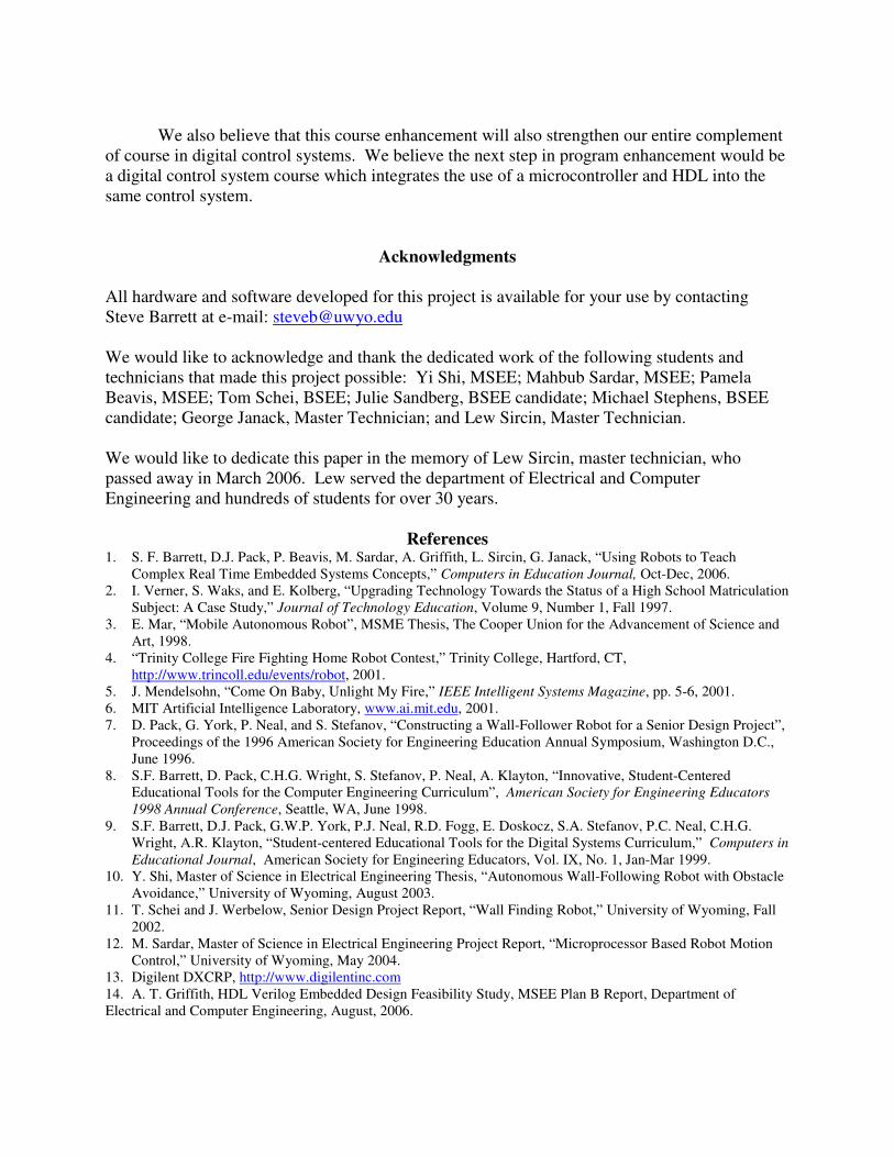
Acknowledgments
All hardware and software developed for this project is available for your use by contacting Steve Barrett at e-mail: [email protected] We would like to acknowledge and thank the dedicated work of the following students and technicians that made this project possible: Yi Shi, MSEE; Mahbub Sardar, MSEE; Pamela Beavis, MSEE; Tom Schei, BSEE; Julie Sandberg, BSEE candidate; Michael Stephens, BSEE candidate; George Janack, Master Technician; and Lew Sircin, Master Technician. We would like to dedicate this paper in the memory of Lew Sircin, master technician, who passed away in March 2006. Lew served the department of Electrical and Computer Engineering and hundreds of students for over 30 years.
References
1. S. F. Barrett, D.J. Pack, P. Beavis, M. Sardar, A. Griffith, L. Sircin, G. Janack, “Using Robots to Teach Complex Real Time Embedded Systems Concepts,” Computers in Education Journal, Oct-Dec, 2006.
2. I. Verner, S. Waks, and E. Kolberg, “Upgrading Technology Towards the Status of a High School Matriculation Subject: A Case Study,” Journal of Technology Education, Volume 9, Number 1, Fall 1997.
3. E. Mar, “Mobile Autonomous Robot”, MSME Thesis, The Cooper Union for the Advancement of Science and Art, 1998.
4. “Trinity College Fire Fighting Home Robot Contest,” Trinity College, Hartford, CT, http://www.trincoll.edu/events/robot, 2001.
5. J. Mendelsohn, “Come On Baby, Unlight My Fire,” IEEE Intelligent Systems Magazine, pp. 5-6, 2001. 6. MIT Artificial Intelligence Laboratory, www.ai.mit.edu, 2001. 7. D. Pack, G. York, P. Neal, and S. Stefanov, “Constructing a Wall-Follower Robot for a Senior Design Project”,
Proceedings of the 1996 American Society for Engineering Education Annual Symposium, Washington D.C., June 1996.
8. S.F. Barrett, D. Pack, C.H.G. Wright, S. Stefanov, P. Neal, A. Klayton, “Innovative, Student-Centered Educational Tools for the Computer Engineering Curriculum”, American Society for Engineering Educators
1998 Annual Conference, Seattle, WA, June 1998. 9. S.F. Barrett, D.J. Pack, G.W.P. York, P.J. Neal, R.D. Fogg, E. Doskocz, S.A. Stefanov, P.C. Neal, C.H.G.
Wright, A.R. Klayton, “Student-centered Educational Tools for the Digital Systems Curriculum,” Computers in
Educational Journal, American Society for Engineering Educators, Vol. IX, No. 1, Jan-Mar 1999. 10. Y. Shi, Master of Science in Electrical Engineering Thesis, “Autonomous Wall-Following Robot with Obstacle
Avoidance,” University of Wyoming, August 2003. 11. T. Schei and J. Werbelow, Senior Design Project Report, “Wall Finding Robot,” University of Wyoming, Fall
2002. 12. M. Sardar, Master of Science in Electrical Engineering Project Report, “Microprocessor Based Robot Motion
Control,” University of Wyoming, May 2004. 13. Digilent DXCRP, http://www.digilentinc.com 14. A. T. Griffith, HDL Verilog Embedded Design Feasibility Study, MSEE Plan B Report, Department of Electrical and Computer Engineering, August, 2006.