a/c-heater system - automatic article text 1989 chrysler...
TRANSCRIPT

A/C-HEATER SYSTEM - AUTOMATICArticle Text
1989 Chrysler LeBaron SedanFor m m m m m
Copyright © 1998 Mitchell Repair Information Company, LLCThursday, July 03, 2003 10:15AM
ARTICLE BEGINNING
1989 AUTOMATIC A/C-HEATER SYSTEMSChrysler Motors - Automatic Temperature Control (ATC)
Chrysler; LeBaron, New Yorker, New Yorker LandauDodge; Dynasty
* PLEASE READ THIS FIRST *
CAUTION: When discharging air conditioning system, use only approvedrefrigerant recovery/recycling equipment. Make every attemptto avoid discharging refrigerant into the atmosphere.
DESCRIPTION
The Automatic Temperature Control (ATC) system automaticallycontrols vehicle interior temperature according to temperaturesetting. The system regulates airflow direction, blower speed, freshair or recirculated air, and the amount of cool or warm air allowedinto system to achieve desired temperature.
The system consists of an ATC computer, blower motor, controlpanel, Power/Vacuum Module (PVM), in-car temperature sensor, andambient temperature sensor.
OPERATION
ATC COMPUTER
The Automatic Temperature Control (ATC) computer is part ofthe control panel. It manages all automatic temperature controlelectrical conponents. The automatic temperature control computerprovides power to the Power/Vacuum Module (PVM) and the blend-air dooractuator according to desired temperature setting and airflowdirection.
BLEND-AIR DOOR ACTUATOR
Blend-air door actuator is an electric servomotor located onbottom of A/C-heater housing. The ATC computer activates the blend-airdoor actuator to open or close to proper position according totemperature setting.
CONTROL PANEL
Control panel allows operator to control various functions ofthe automatic temperature computer control by pushing buttons tochange system modes. Blower speed, temperature selected, airflowdirection, and A/C mode is displayed on control panel.
To change temperature display from Fahrenheit reading toCelsius or back, depress "AUTO" and defrost buttons at the same time.See Fig. 1.
Blower Speed Selector SwitchBlower speed selector button is a rocker type switch. If

A/C-HEATER SYSTEM - AU
switch is pressed on top, blower speed increases. If switch is pressedon bottom, blower speed decreases. Control panel will display segmentshas blower speed is increased.
"A/C" ButtonWhen button is pushed, A/C compressor is turned on. A
snowflake is displayed on control panel when in this mode.
"OFF" ButtonDepressing button shuts the A/C-heater system off. The in-car
sensor and fan motor remain on.
Fig. 1: Automatic Temperature Control PanelCourtesy of Chrysler Motors.
"PANEL" ButtonWhen button is depressed, air is routed to instrument panel
registers. Control panel will display panel symbol (bi-level symbolwithout arrow pointing downward). See Fig. 1.
"AUTO" ButtonWith "AUTO" button depressed, air discharge and blower speed
are controlled automatically. Automatic temperature control range isfrom 65� F (18� C) to 85� F (29� C).
"FLOOR" ButtonWhen button is depressed, airflow is routed to floor outlets.
Control panel will display floor symbol (bi-level symbol without sidearrows). See Fig. 1.
Pressing "PANEL" and "FLOOR" buttons simultaneously willplace system in bi-level mode. Air is discharged through panel andfloor outlets in bi-level mode. Control panel will display bi-levelsymbol.
Defrost ButtonWhen button is depressed, airflow is routed to defroster
vents. Some airflow is routed to floor outlets. The A/C compressorwill operate when in this mode. Control panel will display defrost
A/C-HEATER SYSTEM - A
symbol. See Fig. 1.
Air Temperature Selector SwitchDepressing upper or lower end of air temperature selector
switch will raise or lower temperature setting. The range of comfortsettings are 65� F (18� C) to 85� F (29� C). At "65" and "85" the airtemperature doors lock in minimum or maximum heat positionsrepectively.
With air temperature and "AUTO" mode selected, control ofA/C-heater system is automatic. When vehicle is started, the systemadjusts to rapidly bring interior temperature to desired setting.
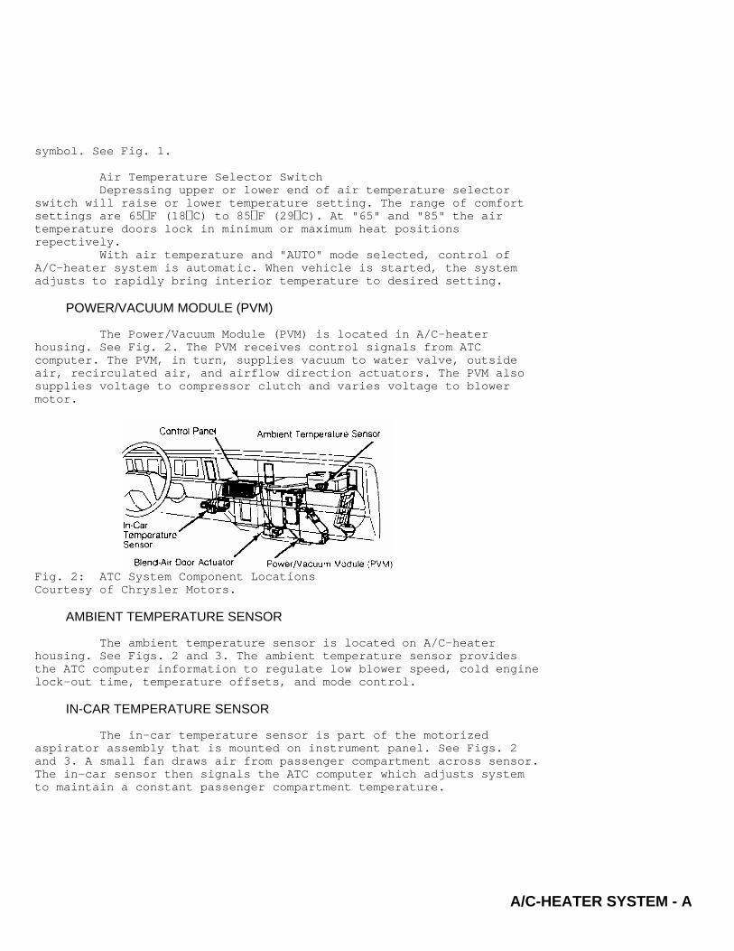
POWER/VACUUM MODULE (PVM)
The Power/Vacuum Module (PVM) is located in A/C-heaterhousing. See Fig. 2. The PVM receives control signals from ATCcomputer. The PVM, in turn, supplies vacuum to water valve, outsideair, recirculated air, and airflow direction actuators. The PVM alsosupplies voltage to compressor clutch and varies voltage to blowermotor.
Fig. 2: ATC System Component LocationsCourtesy of Chrysler Motors.
AMBIENT TEMPERATURE SENSOR
The ambient temperature sensor is located on A/C-heaterhousing. See Figs. 2 and 3. The ambient temperature sensor providesthe ATC computer information to regulate low blower speed, cold enginelock-out time, temperature offsets, and mode control.
IN-CAR TEMPERATURE SENSOR
The in-car temperature sensor is part of the motorizedaspirator assembly that is mounted on instrument panel. See Figs. 2and 3. A small fan draws air from passenger compartment across sensor.The in-car sensor then signals the ATC computer which adjusts systemto maintain a constant passenger compartment temperature.

A/C-HEATER SYSTEM - AUTOMATICArticle Text (p. 4)1989 Chrysler LeBaron SedanFor m m m m mCopyrigh
Fig. 3: Ambient Temperature & In-Car Temperature SensorsCourtesy of Chrysler Motors.
TESTING
ENTERING SELF-TEST & DIAGNOSTIC MODE
Pre-Test Preparation1) Determine if customer complaint is due to system failure
or improper operation of A/C-heater system. System may go into maximumheating or cooling mode if driver rapidly changes temperature settingby four or more digits.
2) Check coolant level, refrigerant charge, compressor drivebelt tension, vacuum hose connections, radiator airflow, radiator fanoperation, and in car-temperature sensor air suction before enteringself-test and diagnostic mode.
3) Bring engine to normal operating temperature and enterself-test and diagnostic mode. Always test the entire system afterrepairs have been performed (if necessary).
Entering Self-Test & Diagnostic ModeA self-test and diagnostic mode has been programmed into the
ATC computer. By depressing "AUTO", "FLOOR" and defrost buttons at thesame time, the computer will flash a failure code on control paneltemperature display. See Figs. 1 and 4.
The system will flash "75" on the control panel if system isokay. A full no failure test will take approximately 1 1/2 minutes.After each failure code is recorded (if any), depress the "PANEL"button to resume test cycle. At end of test cycle, the display willreturn to the selected temperature setting.

A/C-HEATER SYSTEM - AUTOMATICArticle Text (p. 5)1989 Chrysler LeBaron SedanFor m m m m mCopyrigh
Fig. 4: Automatic Temperature Control Diagnostic Flow ChartCourtesy of Chrysler Motors.
NON-COMPUTER AIDED DIAGNOSTICS
Computer Display Does Not Dim With Headlights On1) If computer display does not dim, but other instruments
do, remove automatic temperature control panel and leave wiringharness connected. Check for 4.5 volts between pin No. 10 of 21-pinconnector and body ground. See Fig. 5.
2) Turn instrument illumination dimmer in headlight switch.Voltage should vary from 2 to 12 volts at pins No. 10 and 21 of 21-pinconnector. If voltage is okay, and other electronic displays arenormal, replace ATC computer. If voltage is not okay, repair wiring.
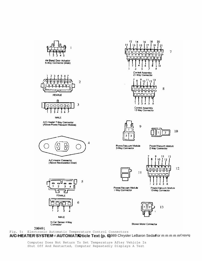
A/C-HEATER SYSTEM - AUTOMATICArticle Text (p. 6)1989 Chrysler LeBaron SedanFor m m m m mCopyrighFig. 5: Electronic Automatic Temperature Control ConnectorsCourtesy of Chrysler Motors.
Computer Does Not Return To Set Temperature After Vehicle IsShut Off And Restarted, Computer Repeatedly Displays A Test

A/C-HEATER SYSTEM -
Complete DisplayReplace automatic temperature control panel. See AUTOMATIC
TEMPERATURE CONTROL PANEL removal and installation in this article.
Push Buttons Stick, Do Not Function Properly, Or PanelDisplay Figures Are Partly IlluminatedPerform a functional/visual inspection to confirm complaint.
If malfuction exists, replace automatic temperature control panel. SeeAUTOMATIC TEMPERATURE CONTROL PANEL removal and installation in thisarticle.
Insufficient Cooling Or Heating With No Failure Code1) Check blend-air door shaft-to-actuator engagement. If
necessary, remove actuator and install properly. With system running,place a small piece of paper over in-car temperature sensor intake. Ifpaper sticks to grille, in-car temperature sensor aspirator is okay.
2) If paper does not stick, but aspirator motor is running,repair in-car temperature sensor foam gasket. If paper does not stick,and aspirator motor is not running, check for battery voltage betweenthe 2 center terminals of in-car temperature sensor connector. Ifvoltage is present, replace in-car temperature sensor.
Blower Motor Operates At High Speed Only And Cannot BeControlled With Blower Speed Selector Switch, No Failure CodeDisplayedSelect a one-bar indicated blower setting. Disconnect the 2-
pin connector from power/vacuum module. If blower stays on high speed,the Black/Tan wire is shorted. Locate and repair short. If blowerstops, replace power/vacuum module.
PRE-COMPUTER AIDED DIAGNOSTICS
Display Symbols And Indicators Do Not Illuminate, No FailureCode Displayed1) After self-test is completed, select a mode that will
display malfunction. If automatic temperature control system operatesproperly and the display does not, perform a visual inspection toconfirm complaint.
2) If malfunction exists, replace automatic temperaturecontrol panel. See AUTOMATIC TEMPERATURE CONTROL PANEL removal andinstallation in this article.
Inoperative Blower Motor, No Failure Code Displayed1) Check all PVM and blower motor wiring connections. Use a
test light to check for 12 volts on both ends of fuse No. 4. Replaceif necessary. If fuse is good, disconnect blower motor wiring harness.
2) Using a voltmeter, check for 12 volts between Green wireon wiring harness and body ground. If there is no voltage, repairwiring. If there is 12 volts, connect negative lead of voltmeter toBlack wire on wiring harness.
3) Using blower speed selector switch, raise and lower blowerspeed indicator on display and observe voltmeter. Reading should be 3volts when in low speed and 12 volts when in high speed.
4) If there is no voltage change, replace PVM and retestsystem. If there is a voltage change and blower is still operative,replace blower motor.
NOTE: Do not run ATC system for more than 10 minutes with PVM

A/C-HEATER SYSTEM - AUT
removed from A/C unit. Stay clear of blower motor and PVMheat sink.
No Airflow To Panel Outlets, No Failure Code Displayed1) With engine running, unplug vacuum connector from PVM.
Using a vacuum gauge, check Black line of vacuum harness for enginemanifold vacuum. Shut engine off. Vacuum should be held by check valvefor 2 minutes.
2) If vacuum is not present or does hold for 2 minutes,repair vacuum hose or replace check valve located over A/C-heaterhousing. If vacuum is present and held for 2 minutes, replacePower/Vacuum Module (PVM) and retest system.
Outlet Air Temperature Does Not Become Hot Then Cycle TooCold During Self-Test, No Failure Code DisplayedSee PRE-TEST PREPARATION and refer to INSUFICIENT COOLING OR
HEATING WITH NO FAILURE CODE in NON-COMPUTER AIDED DIAGNOSTICS portionof this article.
COMPUTER AIDED DIAGNOSTICS
Preliminary Test Steps & Failure Code Information1) See NON-COMPUTER AIDED DIAGNOSTICS before computer aided
diagnostic tests. Hood of vehicle should be closed during diagnostictests to keep engine heat from affecting ambient temperature sensor.
2) Failure Codes No. 1, 2, 3, 11 and 12 involve wiringharness, blend-air door actuator, and ATC computer. Failure Code No. 4involves ATC computer, PVM, and A/C logic circuit. Failure Code No. 5involves wiring harness, A/C switches, ATC computer, and enginecontroller.
3) Failure Codes No. 6, 7, 8 , 9, 10 and 11 involve wiringharness, PVM, and ATC computer. Failure Code No. 15 involve in-cartemperature sensor, wiring harness, and ATC computer. Failure CodesNo. 16, 17 and 18 involve ATC computer.
4) Multiple failure Codes No. 2 or 3, 6, 7, 8, 9, 10, 11, 12and/or 13 indicate that a connector is unplugged or that the ignitionfeed is open to blend-air door actuator or PVM.
5) All voltage tests should be performed with ignition switchin the "RUN" position and voltmeter connected to a known good bodyground.
Failure Codes Involving PVM1) If multiple failure codes involve PVM, check wiring
harness and connections at Power/Vacuum Module (PVM). If okay, go tonext step. If not, correct problem and retest system.
2) Connect voltmeter between pin No. 7 of PVM and bodyground. See Fig. 5. If battery voltage is indicated, replace PVM. Ifnot, connect voltmeter to pin No. 12 of ATC computer.
3) If battery voltage is not found, replace ATC computer. Ifbattery voltage is indicated, repair wiring between pin No. 12 of ATCcomputer and pin No. 7 of PVM.
Failure Codes No. 1, 2 Or 3 Test1) If failure Codes No. 12 or 13 occur with any of these
codes, repair Codes No. 12 or 13 first, and then retest system. Withfailure Codes No. 1 or 2, remove blend-air door actuator. With wiringharness still connected to actuator, retest system.
2) If failure code goes away, check for blend-air door
A/C-HEATER SYSTEM - AUTO
binding inside A/C-heater housing. If failure (code) is still presentor Code No. 3 is present, disconnect and check continuity betweenactuator 5-pin connector and ATC computer 21-pin connector. SeeFAILURE CODES NO. 1, 2 OR 3 TEST table.
FAILURE CODES NO. 1, 2 OR 3 TEST TABLE� � � � � � � � � � � � � � � � � � � � � � � � � � � � � � � � � � � � � � � � � � � � � � � � � � � � � � � � � � � �
ATC Computer 16-Pin Connector Blend-Air DoorPin No. Pin No. Actuator Pin No.
17 ..................... 11 .......................... 318 ..................... 13 .......................... 18 ...................... 15 .......................... 47 ...................... 14 .......................... 5� � � � � � � � � � � � � � � � � � � � � � � � � � � � � � � � � � � � � � � � � � � � � � � � � � � � � � � � � � � �
3) If any circuit is open, repair wiring and retest. Ifcontinuity exists, plug connectors back in. If testing for failureCode No. 1, go to next step. If testing for failure Code No. 2, go tostep 6).
4) Set ATC control panel to "65" and wait 30 seconds. Connecta voltmeter to pin No. 8 of ATC computer. See Fig. 5. Adjusttemperature setting to "85" and monitor voltage. Voltage shouldincrease from its present value to a value greater than 4 volts andthen stop.
5) If value is as indicated and failure Code No. 1 is issued,replace ATC computer. If value is incorrect, replace blend-air dooractuator and retest system. If error code still exists, replace ATCcomputer.
6) Set ATC control panel to "85" and wait 30 seconds. Connecta voltmeter to pin No. 8 of ATC computer. Adjust temperature settingto "65" and monitor voltage. Voltage should decrease from its presentvalue to a value less than one volt.
7) If value is as indicated and failure Code No. 2 is issued,replace ATC computer. If value is incorrect, replace blend-air dooractuator and retest system. If error code still exists, replace ATCcomputer.
Failure Code No. 4 Test1) Manually increase blower speed from one to 8 segments (as
indicated by blower speed symbol). If blower motor goes to high speed,go to step 4). If not, remove ATC computer.
2) Disconnect wiring harness and measure resistance betweenpins No. 2 and 12. See Fig. 5. Resistance should be 2600-2800 ohms. Ifcorrect, replace ATC computer. If not, go to next step.
3) Check continuity between connector pin No. 2 of ATCcomputer and pin No. 13 of Power/Vacuum Module (PVM). If continuity isokay, replace PVM. If no continuity exists, repair wiring and retest.
4) Check to see if A/C compressor cycles on and off bypushing "A/C" button on and off while NOT in defrost mode. Ifcompressor cycles on and off, replace ATC computer. If not, go to nextstep.
5) Unplug low pressure cut-out switch (New Yorker) orelectronic cycling switch (LeBaron) and run self-test again. If CodeNo. 4 DOES NOT appear, problem is between A/C switch and enginecontroller.
6) If Code No. 4 appears again, check continuity betweencycling switch and connector pin No. 13 of ATC computer. If continuity

A/C-HEATER SYSTEM
exists, replace ATC computer. If no continuity exists, repair wiringand retest system.
Failure Code No. 5 Test1) Unplug low pressure cut-out switch (New Yorker) or
electronic cycling switch (LeBaron) and run self-test again. If CodeNo. 5 DOES NOT appear, problem is between A/C switch and enginecontroller.
2) If Code No. 5 appears again, check continuity betweencycling switch and connector pin No. 13 of ATC computer. If continuityexists, replace ATC computer. If no continuity exists, repair wiringand retest system.
Failure Code No. 6 Test1) Remove ATC computer. Disconnect wiring harness and measure
resistance between pins No. 2 and 12. See Fig. 5. Resistance should be2600-2800 ohms. If correct, replace ATC computer. If not, go to nextstep.
2) Check continuity between connector pin No. 2 of ATCcomputer and pin No. 13 of Power/Vacuum Module (PVM). If continuity isokay, replace PVM. If no continuity exists, repair wiring and retest.
Failure Code No. 7 Test1) Depress "OFF" button on control panel. Remove ATC
computer. Measure voltage at pin No. 4 of ATC computer. Reading shouldbe greater than 4 volts. If reading is correct, replace ATC computer.If reading is less than 4 volts, go to next step.
2) If reading is between .4-.8 volts, replace ATC computer.If reading is NOT between .4-.8 volts, unplug 13-pin connector fromPVM. See Fig. 5. Check continuity between connector pin No. 4 of ATCcomputer and pin No. 6 of PVM. If continuity exists, replace PVM. Ifno continuity exists, repair wiring and retest system.
Failure Code No. 8 Test1) Depress defrost button on control panel to set ATC
computer in defrost mode. Remove ATC computer. Measure voltage at pinNo. 5 of ATC computer. Reading should be greater than 4 volts. Ifreading is correct, replace ATC computer. If reading is less than 4volts, go to next step.
2) If reading is between .4-.8 volts, replace ATC computer.If reading is NOT between .4-.8 volts, unplug 13-pin connector fromPVM. See Fig. 5. Check continuity between connector pin No. 5 of ATCcomputer and pin No. 5 of PVM. If continuity exists, replace PVM. Ifno continuity exists, repair wiring and retest system.
Failure Code No. 9 Test1) Depress "OFF" button on control panel. Remove ATC
computer. Measure voltage at pin No. 6 of ATC computer. Reading shouldbe greater than 4 volts. If reading is correct, replace ATC computer.If reading is less than 4 volts, go to next step.
2) If reading is between .4-.8 volts, replace ATC computer.If reading is NOT between .4-.8 volts, unplug 13-pin connector fromPVM. See Fig. 5. Check continuity between connector pin No. 6 of ATCcomputer and pin No. 4 of PVM. If continuity exists, replace PVM. Ifno continuity exists, repair wiring and retest system.
Failure Code No. 10 Test1) Depress "OFF" button on control panel. Remove ATC

A/C-HEATER SYSTEM - AUTOM
computer. Measure voltage at pin No. 15 of ATC computer. Readingshould be greater than 4 volts. If reading is correct, replace ATCcomputer. If reading is less than 4 volts, go to next step.
2) If reading is between .4-.8 volts, replace ATC computer.If reading is NOT between .4-.8 volts, unplug 13-pin connector fromPVM. See Fig. 5. Check continuity between connector pin No. 15 of ATCcomputer and pin No. 2 of PVM. If continuity exists, replace PVM. Ifno continuity exists, repair wiring and retest system.
Failure Code No. 11 Test1) Depress "OFF" button on control panel. Remove ATC
computer. Measure voltage at pin No. 16 of ATC computer. See Fig. 5.Reading should be greater than 4 volts. If reading is correct, replaceATC computer. If reading is less than 4 volts, go to next step.
2) If reading is between .4-.8 volts, replace ATC computer.If reading is NOT between .4-.8 volts, unplug 13-pin connector fromPower Vacuum Module (PVM). Check continuity between connector pin No.16 of ATC computer and pin No. 1 of PVM. If continuity exists, replacePVM. If no continuity exists, repair wiring and retest system.
Failure Codes No. 12 & 13 Test1) Remove ATC computer and disconnect wiring harness. Unplug
connector from blend-air door actuator. Check continuity betweenblend-air door actuator 5-pin connector and ATC computer 21-pinconnector. See FAILURE CODE NO. 12 & 13 TEST table.
2) If any circuits are open, repair wiring and retest. Ifcontinuity exists, plug connectors back in, replace blend-air dooractuator, and retest system. If failure (code) still exists, replaceATC computer.
FAILURE CODE NO. 12 & 13 TEST TABLE� � � � � � � � � � � � � � � � � � � � � � � � � � � � � � � � � � � � � � � � � � � � � � � � � � � � � � � � � � � �
ATC Computer Blend-Air DoorPin No. Actuator Pin No.
12 ..................................................... 217 ..................................................... 318 ..................................................... 1� � � � � � � � � � � � � � � � � � � � � � � � � � � � � � � � � � � � � � � � � � � � � � � � � � � � � � � � � � � �
Failure Code No. 14 Test1) Remove ATC computer and disconnect wiring harness. Check
resistance between connector pins No. 7 and 9 of ATC computer. Withtemperature between 30� F (-1� C) and 120� F (49� C), resistance readingshould be 3000-41,000 ohms. If reading is correct, replace ATCcomputer.
2) If reading is incorrect, unplug 16-pin connector at A/C-heater housing (located above PVM). Check resistance between pins No.10 and 14 on female connector held by metal bracket.
3) If reading is 3000-41,000 ohms, repair wiring between ATCcomputer and 16-pin male connector. If reading is incorrect, removeambient temperature sensor and check its resistance.
4) If resistance is incorrect, replace ambient temperaturesensor. If reading is correct, repair wiring between ambienttemperature sensor and 16-pin female connector.
Failure Code No. 15 Test1) Remove ATC computer and disconnect wiring harness. Check
A/C-HEATER SYSTEM -
resistance between connector pins No. 7 and 20 of ATC computer. Withtemperature between 30� F (-1� C) and 90� F (32� C), resistance readingshould be 5000-41,000 ohms. If reading is correct, replace ATCcomputer.
2) If reading is incorrect, remove in-car temperature sensorand test its resistance across terminals No. 1 and 4. If reading isincorrect, replace in-car temperature sensor. If resistance iscorrect, go to next step.
3) Check continuity between connector pin No. 20 of ATCcomputer and pin No. 1 of in-car temperature sensor connector, andbetween connector pin No. 7 of ATC computer and pin No. 4 of in-cartemperature sensor connector. Repair wiring if necessary.
Failure Codes No. 16, 17 & 18 TestReplace ATC computer and retest system.
REMOVAL & INSTALLATION
AMBIENT TEMPERATURE SENSOR
Removal & InstallationRemove glove box assembly. Remove 2 ambient temperature
sensor mounting screws. Carefully remove sensor from A/C-heaterhousing. Unplug electrical connector from sensor. To install, reverseremoval procedure.
CONTROL PANEL
Removal & InstallationRemove cluster bezel. Remove control panel mounting screws.
Pull control panel out slightly. Unplug electrical and vacuumconnectors. Remove control panel from vehicle. To install, reverseremoval procedure.
BLEND-AIR DOOR ACTUATOR
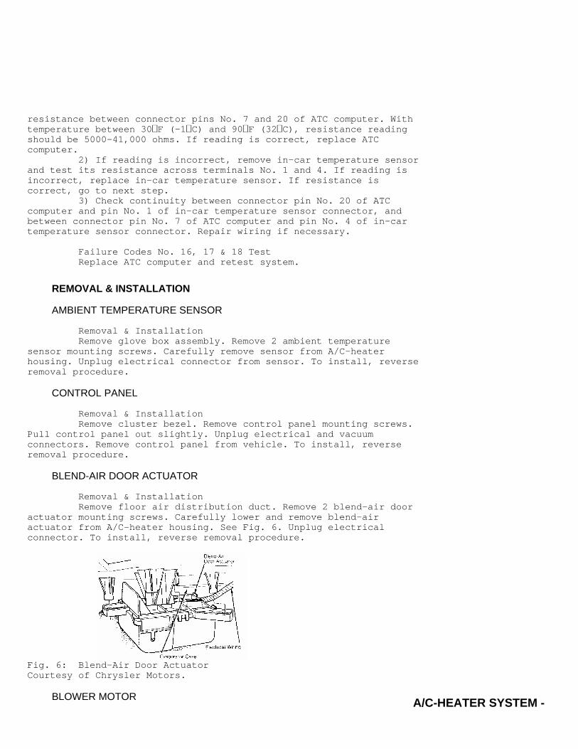
Removal & InstallationRemove floor air distribution duct. Remove 2 blend-air door
actuator mounting screws. Carefully lower and remove blend-airactuator from A/C-heater housing. See Fig. 6. Unplug electricalconnector. To install, reverse removal procedure.
Fig. 6: Blend-Air Door ActuatorCourtesy of Chrysler Motors.
BLOWER MOTOR
A/C-HEATER SYSTEM - AUTOMATICArticle Text (p. 13)1989 Chrysler LeBaron SedanFor m m m m mCopyri
Removal & Installation1) Remove glove box assembly. Disconnect blower motor
electrical connector. Disconnect vent tube from A/C-heater housing.Remove recirculation door actuator from housing with vacuum linesconnected.
2) Remove 7 screws attaching recirculating air housing toA/C-heater housing. Remove recirculating air housing. Remove 3 blowermotor mounting screws. Remove blower motor from A/C-heater housing. Toinstall, reverse removal procedure.
EVAPORATOR & HEATER CORE
Removal & Installation1) Disconnect negative battery cable. Discharge refrigerant
A/C system using approved refrigerant recovery/recycling equipment.Drain coolant from radiator. Remove heater hoses from heater core.Plug heater core tubes to prevent spillage during removal. Disconnectvacuum lines from intake manifold and water valve.
2) Remove right scuff plate from upper quarter trim panel.Remove right cowl side trim panel. Remove glove box assembly. Removeautomatic temperature control panel. Remove upper instrument panelpad.
3) Remove instrument panel mounting screws along windshield.If equipped, remove console assembly and mounting bracket. Remove 2center duct assembly mounting screws. Remove center duct assembly.Remove floor air duct from A/C-heater housing.
4) Remove defroster adapter duct. Remove drain tube fromevaporator. Disconnect electrical connectors. Remove right side cowl-to-plenum brace. Pull carpet away from A/C-heater housing. Removehanger-to-housing mounting screws.
5) Remove 4 A/C-heater mounting nuts from inside enginecompartment. Lift up on dash assembly and pull A/C-heater housing outuntil mounting studs clear dash liner. Remove A/C-heater housing fromvehicle. To install, reverse removal procedure.
IN-CAR TEMPERATURE SENSOR
Removal & Installation1) On LeBaron, remove lower steering column cover. Remove
screws and sensor/aspirator assembly from instrument panel. Unplugelectrical connector. To install, reverse removal procedure.
2) On New Yorker, remove instrument cluster. Remove screwsand sensor/aspirator assembly from instrument cluster opening. Unplugelectrical connector. To install, reverse removal procedure.
POWER/VACUUM MODULE (PVM)
Removal & Installation1) Remove glove box assembly. Remove lower center console
mounting screws. Remove tray mounting screws. Remove lower centerconsole and tray. Unplug electrical connector from ashtray.
2) Remove lower floor and panel air distribution ducts.Remove 4 PVM mounting screws. Unplug electrical and vacuum connectorsfrom module. See Fig. 7. Carefully remove PVM from under instrumentpanel. To install, reverse removal procedure.

A/C-HEATER SYSTEM - AUTOMATICArticle Text (p. 14)1989 Chrysler LeBaron SedanFor m m m m mCopyri
Fig. 7: Power/Vacuum Module (PVM)Courtesy of Chrysler Motors.
MAIN VACUUM DIAGRAM

A/C-HEATER SYSTEM - AUTOMATICArticle Text (p. 15)1989 Chrysler LeBaron SedanFor m m m m mCopyri
Fig. 8: Main Vacuum Diagram
MODE VACUUM DIAGRAM

A/C-HEATER SYSTEM - AUTOMATICArticle Text (p. 16)1989 Chrysler LeBaron SedanFor m m m m mCopyri
Fig. 9: Off Mode Vacuum Diagram

A/C-HEATER SYSTEM - AUTOMATICArticle Text (p. 17)1989 Chrysler LeBaron SedanFor m m m m mCopyri
Fig. 10: Panel Mode Vacuum Diagram
A/C-HEATER SYSTEM - AUTOMATICArticle Text (p. 18)1989 Chrysler LeBaron SedanFor m m m m mCopyri
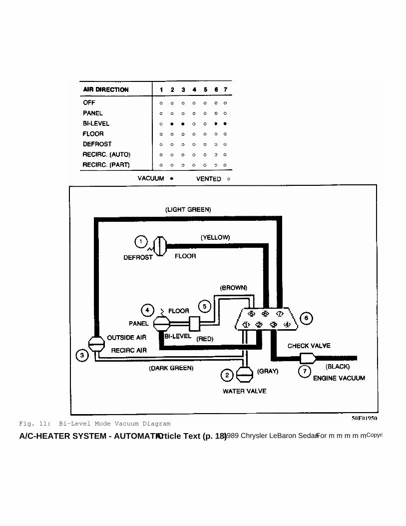
Fig. 11: Bi-Level Mode Vacuum Diagram
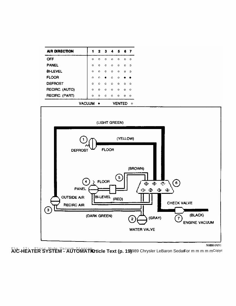
A/C-HEATER SYSTEM - AUTOMATICArticle Text (p. 19)1989 Chrysler LeBaron SedanFor m m m m mCopyriFig. 12: Floor Mode Vacuum Diagram

A/C-HEATER SYSTEM - AUTOMATICArticle Text (p. 20)1989 Chrysler LeBaron SedanFor m m m m mCopyriFig. 13: Defrost Mode Vacuum Diagram

A/C-HEATER SYSTEM - AUTOMATICArticle Text (p. 21)1989 Chrysler LeBaron SedanFor m m m m mCopyriFig. 14: Recirc. (Auto) Mode Vacuum Diagram
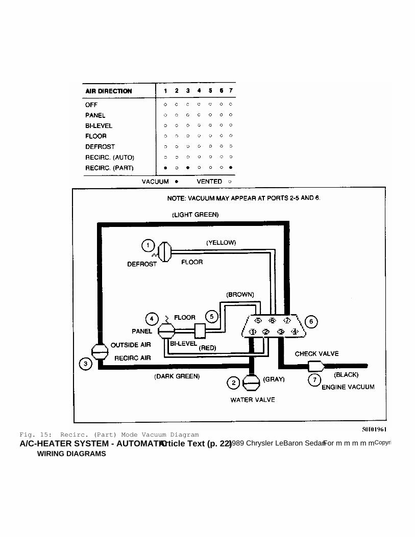
A/C-HEATER SYSTEM - AUTOMATICArticle Text (p. 22)1989 Chrysler LeBaron SedanFor m m m m mCopyriFig. 15: Recirc. (Part) Mode Vacuum Diagram
WIRING DIAGRAMS

A/C-HEATER SYSTEM - AUTOMATICArticle Text (p. 23)1989 Chrysler LeBaron SedanFor m m m m mCopyri
Fig. 16: Automatic A/C-Heater Wiring Diagram - LeBaron

A/C-HEATER SYSTEM - AUTOMATICArticle Text (p. 24)1989 Chrysler LeBaron SedanFor m m m m mCopyri
Fig. 17: Automatic A/C-Heater Wiring Diagram - Dynasty, NewYorker & New Yorker Landau
END OF ARTICLE