ac input as - spinet.biz.pl filestepping motors intro duction as asc 5-phase rk 5-phase crk ac input...
TRANSCRIPT

Step
pin
g M
oto
rsIn
tro d
uctio
nA
SA
SC5-P
hase
RK
5-Ph
aseCR
KA
C In
pu
tA
C In
pu
tD
C In
pu
t
2-Ph
aseCM
K2-P
hase
CSK
2-Ph
aseS
tepp
ing
Mo
tors
5-Ph
aseS
tepp
ing
Mo
tors
Co
ntro
llersA
ccessories
Installatio
n
DC
Inp
ut
C-187
Page
2-Phase Stepping Motors ······································· C-1885-Phase Stepping Motors ······································· C-242
Stepping Motors
2-Phase Stepping Motors
5-Phase Stepping Motors
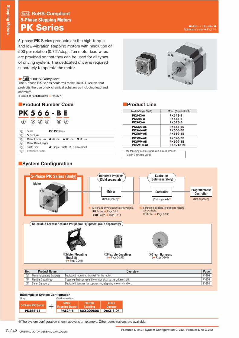
System Configuration
(Sold separately)
PK566-BE
�Example of System Configuration(Body)
5-Phase PK SeriesClean
DamperD6CL-8.0F
FlexibleCoupling
MCS200808
MotorMounting Bracket
PAL2P-5
No. Product Name Overview PageC-266C-258C-264
�
�
�
Motor Mounting BracketsFlexible CouplingsClean Dampers
Dedicated mounting bracket for the motor.Coupling that connects the motor shaft to the driven shaft.Dedicated damper for suppressing stepping motor vibration.
5-Phase PK Series (Body)
Motor
Driver
(Not supplied)✽1
Required Products(Sold separately)
✽1 Motor and driver packages are available. RK Series ➜ Page C-82 CRK Series ➜ Page C-114
✽2 Controllers suitable for stepping motors are available.
Controller ➜ Page C-248
Controller(Sold separately)
Controller
(Not supplied)✽2
ProgrammableController
(Not supplied)
Selectable Accessories and Peripheral Equipment (Sold separately)
�Motor Mounting Brackets
(➜ Page C-266)
�Flexible Couplings (➜ Page C-258)
�Clean Dampers(➜ Page C-264)
�The system configuration shown above is an example. Other combinations are available.
�
5-phase PK Series products are the high-torque and low-vibration stepping motors with resolution of 500 per rotation (0.72°/step). Ten motor lead wires are provided so that they can be used for all types of driving system. The dedicated driver is required separately to operate the motor.
RoHS-CompliantThe 5-phase PK Series conforms to the RoHS Directive that prohibits the use of six chemical substances including lead and cadmium.
Details of RoHS Directive ➜ Page G-23
�
�
Product Number Code
� � � � ��
PK 5 6 6 - B E
� Series PK: PK Series� 5: 5-Phase� Motor Frame Size 4: 42 mm 6: 60 mm 9: 85 mm� Motor Case Length� Shaft Type A: Single Shaft B: Double Shaft� Reference Code
� Product LineModel (Single Shaft) Model (Double Shaft)
PK543-APK544-APK545-A
PK543-BPK544-BPK545-B
PK564-AEPK566-AEPK569-AE
PK564-BEPK566-BEPK569-BE
PK596-AEPK599-AEPK5913-AE
PK596-BEPK599-BEPK5913-BE
Motor, Operating ManualThe following items are included in each product.
�
5-Phase Stepping Motors
PK Series
RoHS-Compliant
�Additional Information�Technical reference ➜ Page F-1
ORIENTAL MOTOR GENERAL CATALOGUE
Step
pin
g M
oto
rs
Features C-242 / System Configuration C-242 / Product Line C-242C-242

Specifications
Frame Sizemm
Model MaximumHolding Torque
N·m
Rotor Inertia
J: kg·m2
Currentper Phase A/Phase
Resistanceper Phase
/Phase
Basic Step Angle
Mass
kg
Corresponding Motor and Driver Package/Page with Speed – Torque
Characteristics
DimensionNo.
Single Shaft Double Shaft
�42PK543-A PK543-B 0.13 35�10-7
0.75
1.7
0.72˚
0.21 CRK543�P C-123�1PK544-A PK544-B 0.18 54�10-7
2.20.27 CRK544�P C-123
PK545-A PK545-B 0.24 68�10-7 0.35 CRK545�P C-123
�60
PK564-AE PK564-BE 0.42 175�10-7 2.3 0.6 � �
�2PK566-AE PK566-BE 0.83 280�10-7 3.4 0.8 � �
PK569-AE PK569-BE 1.66 560�10-7
1.41.7 1.3 RK569�CE
CRK569�PC-89C-123
�85PK596-AE PK596-BE 2.1 1400�10-7 1.5 1.7 RK596�CE C-89
�3PK599-AE PK599-BE 4.1 2700�10-7 2.3 2.8 RK599�CE C-89PK5913-AE PK5913-BE 6.3 4000�10-7 2.8 0.75 3.8 � �
How to read specifications table ➜ Page C-10For the speed – torque characteristics of the motors in the table above, see the characteristics of the corresponding motor and driver package. If there is no corresponding model, refer to the following characteristics.Enter the shaft type A or B in the box (�) within the model name.
Speed – Torque Characteristics How to read speed – torque characteristics ➜ Page C-10
�
�
�
�
Pulse Speed [kHz]0 15 20105 Full Step
1500 250020001000500Speed [r/min]
Torq
ue [N
�m]
0
0.6
0.2
0.1
0.3
0.4
0.5
0
Constant Current Driver Power Input: 24 VDCCurrent: 0.75 A/Phase (4 Phases ON)With Damper D6CL-8.0F: JL=140�10�7 kg�m2
fs
Pullout Torque
Full Step 0.72°/step
PK564-AE/PK564-BE
Pulse Speed [kHz]0 6 842 Full Step
1000500Speed [r/min]
Torq
ue [N
�m]
0
1.2
0.4
0.2
0.6
0.8
1.0
0
Constant Current Driver Power Input: 24 VDCCurrent: 0.75 A/Phase (4 Phases ON)With Damper D6CL-8.0F: JL=140�10�7 kg�m2
fs
Pullout Torque
Full Step 0.72°/step
PK566-AE/PK566-BE
Note:Pay attention to heat dissipation from motor as there will be a considerable amount of heat under certain conditions. Be sure to keep the temperature of the motor case under 100˚C.�
100 15050 250 300200 350
0 1 2
0
2
4
6
8
10
fs0
Constant Current Driver Power Input: 24 VDCCurrent: 2.8 A/Phase (4 Phases ON)With Damper D9CL-14F: JL=870�10�7 kg�m2
Full Step 0.72°/step
Pullout Torque
Pulse Speed [kHz]Full Step
Speed [r/min]
Torq
ue [N
�m]
PK5913-AE/PK5913-BE
Step
pin
g M
oto
rsIn
tro d
uctio
nA
SA
SC5-P
hase
RK
5-Ph
aseCR
KA
C In
pu
tA
C In
pu
tD
C In
pu
t
2-Ph
aseCM
K2-P
hase
CSK
2-Ph
aseS
tepp
ing
Mo
tors
5-Ph
aseS
tepp
ing
Mo
tors
Co
ntro
llersA
ccessories
Installatio
n
DC
Inp
ut
Specifications, Characteristics C-243 / Dimensions C-245 C-243

Permissible Overhung Load and Permissible Thrust LoadUnit � N
ModelPermissible Overhung Load
Distance from Shaft End (mm) PermissibleThrust Load
0 5 10 15 20
PK54��-� 20 25 34 52 � The permissible thrust load shall be no greater than the motor mass.
PK56��-�E 63 75 95 130 190
PK59��-�E 260 290 340 390 480
Enter the shaft type A or B in the box (�) within the model name.Enter the motor case length in the box (��) within the model name.
Inner Connection Diagram for MotorGreen Blue
Red
White
Yellow
Brown
Orange
Gray
Black
Violet
A-PhaseE-Phase
B-Phase
C-Phase
D-Phase
General SpecificationsSpecifications Motor
Insulation Class Class B (130˚C)
Insulation Resistance100 M� or more when 500 VDC megger is applied between the windings and the case under normal ambient temperature and humidity.
Dielectric StrengthSufficient to withstand 1.0 kV at 50 Hz or 60 Hz applied between the windings and the case for 1 minute under normal ambient temperature and humidity. (0.5 kV for PK54�)
Operating Environment(In operation)
Ambient Temperature �10��50˚C (non-freezing)Ambient Humidity 85% or less (non-condensing)Atmosphere No corrosive gases, dust, water or oil
Temperature RiseTemperature rise of the windings are 80˚C or less measured by the resistance change method.
(at rated current, at standstill, five phases energized)
Stop Position Accuracy✽1 �3 arc minutes (�0.05˚)Shaft Runout 0.05 T.I.R. (mm)✽4
Radial Play✽2 0.025 mm max. of 5 N
Axial Play✽3 0.075 mm max. of 10 NConcentricity 0.075 T.I.R. (mm)✽4
Perpendicularity 0.075 T.I.R. (mm)✽4
1 This value is for full step under no load. (The value changes with the size of the load.)2 Radial Play: Displacement in shaft position in the radial direction, when a 5 N load is applied in the vertical direction to the tip of the motor's shaft. 3 Axial Play: Displacement in shaft position in the axial direction, when a 10 N load is applied to the motor's shaft in the axial direction.4 T.I.R. (Total Indicator Reading): The total dial gauge reading when the measurement section is rotated one revolution centered on the reference axis center.
Note:Do not measure insulation resistance or perform the dielectric strength test while the motor and driver are connected.
�
�
�
�
✽
✽
✽
✽
�
A
A0.075
A�0.075
0.05
ORIENTAL MOTOR GENERAL CATALOGUE
Step
pin
g M
oto
rs
Features C-242 / System Configuration C-242 / Product Line C-242C-244

Dimensions (Unit = mm)
�1 �42 mm
Model L1 L2 Masskg
PK543-A33
�0.21
PK543-B 48PK544-A
39�
0.27PK544-B 54PK545-A
47�
0.35PK545-B 62
�
UL Style 3265, AWG26
4�M3�4.5 Deep10 Motor Leads 300 mm Length
2
4.5�
0.15
4231�0.2
31�
0.2
✽15�1 L1L2 20�1
15�0.25
4.5�
0.15
425�
0.01
2(h7
)0 5�
0.01
2(h7
)0
22
�0.
033(
h8)
0
✽ The length of machining on double shaft model is 15�0.25.
�2 �60 mm
Model L1 L2 Masskg
PK564-AE46.5
�0.6
PK564-BE 69.5PK566-AE
57.5�
0.8PK566-BE 80.5PK569-AE
87�
1.3PK569-BE 110
L17 1.5
23�1
UL Style 3266, AWG2610 Motor Leads 300 mm Length
20�0.25
4�4.5 Thru60
50�
0.35
50�0.35
60
20�0.25
L2 24�1
8�
0.01
5(h7
)0
8�
0.01
5(h7
)0
36
�0.
039(
h8)
0
�3 �85 mm
Model L1 L2 Masskg
PK596-AE66
�1.7
PK596-BE 100PK599-AE
96�
2.8PK599-BE 130PK5913-AE
126�
3.8PK5913-BE 160
L137�1L2
10 234�1
70�
0.35
70�0.35
4�6.5 Thru
10 Motor Leads 300 mm LengthUL Style 3265, AWG22
25�0.25 25�0.25
85
14
�0.
018(
h7)
0
14
�0.
018(
h7)
0
60
�0.
046(
h8)
0 85
These dimensions are for double shaft models. For single shaft models, ignore the orange (��) areas.�
Step
pin
g M
oto
rsIn
tro d
uctio
nA
SA
SC5-P
hase
RK
5-Ph
aseCR
KA
C In
pu
tA
C In
pu
tD
C In
pu
t
2-Ph
aseCM
K2-P
hase
CSK
2-Ph
aseS
tepp
ing
Mo
tors
5-Ph
aseS
tepp
ing
Mo
tors
Co
ntro
llersA
ccessories
Installatio
n
DC
Inp
ut
Specifications, Characteristics C-243 / Dimensions C-245 C-245
Step
pin
g M
oto
rsIn
tro d
uctio
nA
SA
SC5-P
hase
RK
5-Ph
aseCR
KA
C In
pu
tA
C In
pu
tD
C In
pu
t
2-Ph
aseCM
K2-P
hase
CSK
2-Ph
aseS
tepp
ing
Mo
tors
5-Ph
aseS
tepp
ing
Mo
tors
Co
ntro
llersA
ccessories
Installatio
n
DC
Inp
ut
C-251
Page
Cables ··································································· C-252Flexible Couplings ················································· C-258Clean Dampers ······················································ C-264Motor Mounting Brackets ······································· C-266DIN Rail Mounting Plate ········································ C-270
Stepping Motors
Accessories
Accessories

CablesVarious cables provide convenient connection between a motor, driver and controller.
Type of Cables
Motor Cable
Stepping Motor
Driver Driver Cable
Communication Cable
Controllers
Personal Computer
General-Purpose Typeor
Connector--Terminal BlockConversion Unit
or
�
Motor Cables
These cables are available to extend the distance between the motor and the driver for and RK Series, or connect a high-torque type motor to a driver.
Cable Name Page Applicable Product
Extension CablesExtension Cables for Electromagnetic Brake Motor
C-253 �1
Flexible Extension CablesFlexible Extension Cables for Electromagnetic Brake Motor
C-253 �2
Motor Cables for IP65 Rated MotorFlexible Motor Cables for IP65 Rated Motor
C-254 �3
Extension Cables C-254 �4 RK Series
Motor Cable C-254 �5RK Series2-Phase PK Series
Motor Lead Wire/Connector Assembly✽ C-255 �6CRK Series
CMK Series2-Phase PK Series
Motor Connector Set✽ C-255 �7CRK Series
CMK Series2-Phase PK Series
Only for connector-coupled motors
Communication Cable
This cable is used to connect personal computer and the AS Series built-in controller (stored program) package through an RS-232C connection.
Cable Name Page Applicable Product
Communicaiton Cable C-257 �4AS Series Built-In Controller
(Stored Program) Package
✽
Driver Cables
Use these cables to connect the driver of the or RKSeries to a controller.Choose the general-purpose type to be combined with a connector appropriate for the specific controller used, or the connector-terminal block conversion unit that permits connection between the driver and host controller using a terminal block.
Cable Name Page Applicable Product
Driver Cables General-Purpose Type C-256 �1RK Series
Connector–Terminal Block Conversion Unit C-256 �2RK Series
Lead wire set is available for connection between DC input driver and motor, controller, and power supply. As driver side of the cable is crimped with connector, easy connection is possible.
Cable Name Page Applicable Product
Driver Lead Wire Set C-257 �3CRK SeriesCMK Series
The driver lead wire set includes three lead wire/connector assemblies (for motor, input/output signal and power supply).
Stepping Motor
Driver Controllers
For Motor
For Power Supply Power
Supply
For Input/Output Signal
ORIENTAL MOTOR GENERAL CATALOGUE
Step
pin
g M
oto
rs
C-252

�1 Extension Cables Extension Cables for Electromagnetic Brake Motor (For )
These cables are used to connect motors and drivers.
Product LineExtension Cables
Model Length L (m)
CC01AIP 1
CC02AIP 2
CC03AIP 3
CC05AIP 5
CC07AIP 7
CC10AIP 10
CC15AIP 15
CC20AIP 20
� Extension Cables for Electromagnetic Brake Motor
Model Length L (m)
CC01AIPM 1
CC02AIPM 2
CC03AIPM 3
CC05AIPM 5
CC07AIPM 7
CC10AIPM 10
CC15AIPM 15
CC20AIPM 20
�
Notes:Electromagnetic brake models must use an extension cable for an electromagnetic brake motor. But for electromagnetic brake motor with motor frame size �42 mm, use an extension cable for standard motor.ASC Series cannot use extension cables of 15 m and 20 m.
Dimensions (Unit = mm)
For Standard Motor
24.3
22.2
L12
�8
(30)
(14.5)11.6
Motor Side Driver Side
For Electromagnetic Brake Motor
22.2
(30)
(14.5)11.6L12
24.3
�8
Driver SideMotor SideElectromagnetic Brake Leads 60 mm Length (Orange/Black, Gray AWG24)
�
�
�
��
�
�2 Flexible Extension Cables Flexible Extension Cables for Electromagnetic Brake Motor (For )
Theses flexible extension cables are used between motors and drivers. We recommend this cable when the motor is installed on a moving section and the cable is bent and flexed.
Product LineFlexible Extension Cables
Model Length L (m)
CC01SAR 1
CC02SAR 2
CC03SAR 3
CC05SAR 5
CC07SAR 7
CC10SAR 10
� Flexible Extension Cables for Electromagnetic Brake Motor
Model Length L (m)
CC01SARM2 1
CC02SARM2 2
CC03SARM2 3
CC05SARM2 5
CC07SARM2 7
CC10SARM2 10
�
Note:For electromagnetic brake motor with motor frame size �42 mm, use a flexible extension cable for standard motor.
Dimensions (Unit = mm)
For Standard Motor
24.3
22.2
L12
�9.5
(30)
(14.5)11.6
Motor Side Driver Side
For Electromagnetic Brake Motor
24.3
22.2
L12
�9.5
(30)
(14.5)11.6
Motor Side Driver Side
Electromagnetic Brake Leads 60 mm Length (Orange, Gray AWG22)
Notes on Use of a Flexible Extension Cable� Do not allow the cable to bend at the
cable connector.� Keep the bending radius to 60 mm or
more.
� The motor cable is not a flexible cable. If the motor cable is to be bent, bend it at the flexible extension cable.
Motor
DriverMotor Cable (Affix the cable.)
Flexible Extension Cable (Possible to bend)
�
�
��
�
�
Motor Cables
Step
pin
g M
oto
rsIn
tro d
uctio
nA
SA
SC5-P
hase
RK
5-Ph
aseCR
KA
C In
pu
tA
C In
pu
tD
C In
pu
t
2-Ph
aseCM
K2-P
hase
CSK
2-Ph
aseS
tepp
ing
Mo
tors
5-Ph
aseS
tepp
ing
Mo
tors
Co
ntro
llersA
ccessories
Installatio
n
DC
Inp
ut
C-253

�3 Motor Cables for IP65 Rated Motor Flexible Motor Cables for IP65 Rated Motor (For )
These motor cables must be used for connection between the AS Series IP65 rated motor and the driver.
Any IP65 rated motor cannot be driven without these cables.One end of the cable connects to the metal connector on the motor, while the other end connects to the driver.Use a flexible motor cable if the motor is installed on a moving part and its cable will be flexed.
Product LineMotor Cables for IP65 Rated Motor
Model Length L (m)
CC01AST 1
CC02AST 2
CC03AST 3
CC05AST 5
CC07AST 7
CC10AST 10
CC15AST 15
CC20AST 20
� Flexible Motor Cables for IP65 Rated Motor
Model Length L (m)
CC01SAR2 1
CC02SAR2 2
CC03SAR2 3
CC05SAR2 5
CC07SAR2 7
CC10SAR2 10
�
Dimensions (Unit = mm)
Motor Cables for IP65 Rated Motor
11.614.5 L
19.626
51.1�8
RC�09S1N1280S1(CONINVERS)
Motor SideDriver Side
22.2
5557�10R(MOLEX)
Flexible Motor Cables for IP65 Rated Motor
11.614.5 L
19.626
51.1�9.5
RC�09S1N1280U1(CONINVERS)
22.2
5557�10R(MOLEX)
Motor SideDriver Side
�
��
�
�4 Extension Cables (For RK Series)
These extension cables are used between RK Series motors and dedicated drivers (except for electromagnetic brake type). They come in three lengths: 5 m, 10 m and 20 m.
Product LineModel Length (m) Conductors
CC05PK5 55CC10PK5 10
CC20PK5 20
Conductor configuration: 5Conductor size: AWG22 (0.3 mm2)Finished outer diameter: �7.2 mmCable rating: 105˚COuter casing: Oil-resistant, heat-resistant, non-migrating vinyl
Note:These extension cables are only for the RK Series. Do not use them on other stepping motor and driver packages (such as CRK Series or CMK Series).
�5 Motor Cable (For IP65 Rated Motor of RK Series and 2-Phase PK Series)
A cable for connection between the IP65 rated motor and driver (with protective earth wire)
Product LineModel Length (m) Conductors
CC03PKT 3 6
Conductor configuration: 6Conductor size: Motor wire AWG18 (0.75 mm2), protective earth wire AWG14 (2.0 mm2)Finished outer diameter: �12 mmCable rating: 105˚C 600 VOuter casing: Heat-resistant, oil-resistant vinyl chloride resinApplicable standards: UL 758 (AWM) VW-1, UL Style 2586
15
23
4
Motor Wire (Black) AWG18 (0.75 mm2)Each core is designated by a number (White).
Inclusion
Securing Tape
Heat-Resistant, Oil-Resistant Vinyl Chloride Resin (Black)
Protective Earth Wire (Green/Yellow) AWG14 (2.0 mm2)
�
�����
�
�
������
ORIENTAL MOTOR GENERAL CATALOGUE
Step
pin
g M
oto
rs
C-254

�6 Motor Lead Wire/Connector AssemblyThese lead wires with connectors are available for connection with the connector-coupled motor, eliminating the need for assembling a connector. (A motor lead wire/connector assembly of 0.6 m is included with the connector-coupled motor packages.)
Product Line
Model Applicable Product Applicable Motor ModelLength
(m)
LC5N06ACRK513P��PCRK513P��P-H��
CRK52�P��PCRK52�PM��PCRK523P��P-T��
CRK523P��P-N��
PK513P��
PK513P��-H��SPK52�P��
PK52�PM��
PK523P��-T��
PK523P��-N��
0.6
LC5N10A 1
LC5N06B CRK54�P��PCRK54�PM��P
PK54�P��
PK54�PM��
0.6
LC5N10B 1
LC5N06CCRK56�PM��P PK56�PM��
0.6
LC5N10C 1
LC2U06A CMK22�P��PCMK223��P-SG��
PK22�P��
PK223P��-SG��
0.6
LC2U10A 1
LC2U06B CMK23�P��PCMK24�P��P
PK23�P��
PK24�P��
0.6
LC2U10B 1
Enter the motor case length in the box (�) within the model name.Enter A (single shaft) or B (double shaft) in the box (��) within the model name.Enter the gear ratio in the box (��) within the model name.
�
�
�7 Motor Connector Set
This photograph shows CS5N30B.
A set of connector housings and contacts for use with connector-coupled motors.Each package contains enough housings and contacts for 30 motors.
Product LineModel Applicable Product Applicable Motor Model
CS5N30A
CRK513P��PCRK513P��P-H��
CRK52�P��PCRK52�PM��PCRK523P��P-T��
CRK523P��P-N��
PK513P��
PK513P��-H��SPK52�P��
PK52�PM��
PK523P��-T��
PK523P��-N��
CS5N30B CRK54�P��PCRK54�PM��P
PK54�P��
PK54�PM��
CS5N30C CRK56�PM��P PK56�PM��
CS2U30A CMK22�P��PCMK223��P-SG��
PK22�P��
PK223P��-SG��
CS2U30B CMK23�P��PCMK24�P��P
PK23�P��
PK24�P��
Enter the motor case length in the box (�) within the model name.Enter A (single shaft) or B (double shaft) in the box (��) within the model name.Enter the gear ratio in the box (��) within the model name.
�
�
Specifications
ModelConnectorHousing
ContactApplicable Crimp Tool
Manufacturer Applicable Cable
CS5N30A 51065-0500 50212-8100 57176-5000
MOLEX
AWG30�24 (0.05�0.2 mm2)Outer Sheath Diameter: �1.4 mm max.Strip Length: 1.3�1.8 mm
CS5N30B 51103-0500 50351-8100 57295-5000AWG28�22 (0.08�0.3 mm2)Outer Sheath Diameter: �1.15�1.8 mmStrip Length: 2.3�2.8 mm
CS5N30C 51144-0500 50539-8100 57189-5000AWG24�18 (0.2�0.75 mm2)Outer Sheath Diameter: �1.4�3 mmStrip Length: 3�3.5 mm
CS2U30A 51065-0600 50212-8100 57176-5000AWG30�24 (0.05�0.2 mm2)Outer Sheath Diameter: �1.4 mm max.Strip Length: 1.3�1.8 mm
CS2U30B 51103-0600 50351-8100 57295-5000AWG28�22 (0.08�0.3 mm2)Outer Sheath Diameter: �1.15�1.8 mmStrip Length: 2.3�2.8 mm
Note:The crimp tool is not provided with the package. It must be purchased separately.
�
�
Step
pin
g M
oto
rsIn
tro d
uctio
nA
SA
SC5-P
hase
RK
5-Ph
aseCR
KA
C In
pu
tA
C In
pu
tD
C In
pu
t
2-Ph
aseCM
K2-P
hase
CSK
2-Ph
aseS
tepp
ing
Mo
tors
5-Ph
aseS
tepp
ing
Mo
tors
Co
ntro
llersA
ccessories
Installatio
n
DC
Inp
ut
C-255

Driver Cables�1 General-Purpose Type
This is a shielded cable equipped with, at one end of the cable, the half-pitch connector that snaps into the driver for and RKSeries.
Notes:Note that as the length of the pulse signal line between the driver and controller increases, the maximum transmission frequency decreases.Technical reference ➜ Page F-46Install a connector that matches the controller you are using to the other end of the cable.
Product LineModel Length L (m) Applicable Connector
CC20D1-1 1 AS Series Built-In Controller (Stored Program) Package CN5 (20 Pins), RK Series CN1 (20 Pins) CC20D2-1 2
CC36D1-1 1 AS Series Pulse Input Package CN4 (36 Pins), AS Series Built-In Controller (Stored Program) Package CN4 (36 Pins), ASC Series CN3 (36 Pins) CC36D2-1 2
Dimensions (Unit = mm)
CC20D1-1, CC20D2-1Conductor: AWG28 (0.08 mm2)
L
1.27
Laminate12.7
33.3
10�3
10�3
60�
15
�6.4
30�100
Shield
10�3
Driver Side Controller Side
CC36D1-1, CC36D2-1Conductor: AWG28 (0.08 mm2)
L
1.27
Laminate12.7
43.4
6
10�3
10�310�360
�15
�7.5
Shield
30�100
Driver Side Controller Side
�
�
�
�
�2 Connector – Terminal Block Conversion Unit
A conversion unit that connects a driver to a host controller using a terminal block. � With a signal name plate for easy, one-glance identification of driver signal names
� DIN-rail mountable� Cable length: 1 m
CC20T1 CC36T1
Product LineModel Length (m) Applicable Connector
CC20T1
1
AS Series Built-In Controller (Stored Program) Package CN5 (20 Pins), RK Series CN1 (20 Pins)
CC36T1
AS Series Pulse Input Package CN4 (36 Pins), AS Series Built-In Controller (Stored Program) Package CN4 (36 Pins), ASC Series CN3 (36 Pins)
Dimensions (Unit = mm)
CC20T1
31 2 4 5 6 7 8 9 1011 12 13 14 15 16 17 18 19 20
1426
36
6.35 1.27 7.62
6586
433
61
54
40
Terminal Block Pin No.
2��4.5 Mounting Holes2��8 Countersink�3.5 Deep
DIN Rail
1000
33.3
33.3
39883912.7 12.7
�
�
ORIENTAL MOTOR GENERAL CATALOGUE
Step
pin
g M
oto
rs
C-256

CC36T1
326 27 28 29 30
1 2 4 5 631 32 33 34 35
7 8 9 10 11 12 13 14 15 16 17 1819 3620 21 22 23 24 25
816.35 1.27 7.62
120162
1426
36
3
61
54
40
Terminal Block Pin No.
2��4.5 Mounting Holes2��8 Countersink�3.5 Deep
DIN Rail
1000
43.4
6
43.4
6398839
12.7 12.7
Recommended Crimp Terminals� Terminal screw size: M3� Tightening torque: 1.2 N�m� Applicable minimum lead wire: AWG22 (0.3 mm2)
3.2 mm min.
6.2
mm
max
.
5.8 mm min.4.2 mm max.
�3 Driver Lead Wire Set As an accessory for DC input drivers, lead wires with a connector are available. Crimping is not necessary, and the connection with the motor, power supply, input/output signal is also easy. The driver lead wire set includes three lead wire/connector assemblies (for motor, power supply and input/output signal).
Product LineModel Applicable Product Applicable Driver Length (m)
LCS04SD5 CRK SeriesCRD5103PCRD5107PCRD5114P
0.6
LCS01CMK2 CMK SeriesCMD2109PCMD2112PCMD2120P
�4 Communication Cable FC04W5This cable is used to connect personal computer and the AS Series built-in controller (stored program) driver through an RS-232C connection.
Cable Length: 5 m
�
�
Step
pin
g M
oto
rsIn
tro d
uctio
nA
SA
SC5-P
hase
RK
5-Ph
aseCR
KA
C In
pu
tA
C In
pu
tD
C In
pu
t
2-Ph
aseCM
K2-P
hase
CSK
2-Ph
aseS
tepp
ing
Mo
tors
5-Ph
aseS
tepp
ing
Mo
tors
Co
ntro
llersA
ccessories
Installatio
n
DC
Inp
ut
C-257

Coupling Selection Table
ModelGear Ratio Motor Shaft
Diameter (mm) TypeDriven Shaft Diameter (mm)
AS ASC �4 �5 �6 �6.35 �8 �10 �12 �14 �15 �16 �18 �20 �25
�ASC34AKASC36AKASC46�K
��5 MCS14 � � �
� ASC34AK-T�� 7.2, 10, 20, 30� ASC46�K-T�� 3.6, 7.2, 10 �6
MCS20� � � � �
� ASC34AK-N�� 5, 7.2, 10 �8 � � � � �
� ASC46�K-T�� 20, 30 �6
MCS30
� � � �
AS66�CEAS66ACTAS66�CEPAS66ACTPAS69�CEAS69ACTAS69�CEPAS69ACTP
ASC66�K �
�8 � � � � �
AS66�CE-T��
AS66�CEP-T��ASC66�K-T�� 3.6, 7.2
� ASC34AK-H�� 50, 100� ASC46�K-N�� 7.2, 10 �10 � � � � � �
AS98�CEAS98ACTAS98�CEPAS98ACTPAS911ACEAS911ACTAS911ACEPAS911ACTP
� � �14 � � � �
AS66�CE-T��
AS66�CEP-T��ASC66�K-T�� 10, 20, 30 �8
MCS40
� � � �
� ASC46�K-H�� 50, 100 �10 � � � �
AS66�CE-P�� � 5, 7.2�12 � � � �AS66�CE-N��
AS66�CEP-N��ASC66�K-N�� 5, 7.2
AS98�CE-T��
AS98�CEP-T���
3.6, 7.2, 10,20, 30
�12 MCS55 � � � �
AS66�CE-P�� � 10, 25, 36, 50AS66�CE-N��
AS66�CEP-N��ASC66�K-N�� 10, 25, 36, 50
AS66�CE-H��
AS66�CEP-H��ASC66�K-H�� 50, 100
Enter A (standard) or M (electromagnetic brake) in the box (�) within the model name.Enter the gear ratio in the box (��) within the model name.
�
�
�
Flexible Couplings A flexible coupling ideal for your motor is available. Once you have decided on a motor and gear, you can select the recommended coupling easily.
Features of MCS CouplingsThis three-piece coupling adopts an aluminum alloy hub and a resin spider. The simple construction ensures that the high torque generated by a geared motor can be transmitted reliably. The proper elasticity of the spider suppresses motor vibration.Technical reference ➜ Page F-46
High strength (usable for geared motor) has been realized.A spider (material: polyurethane) controls the vibration generated by the motor.No backlash
�
���
Product Number Code
MCS 30 08 12� � � �
� MCS Couplings� Outer Diameter of Coupling� Inner Diameter d1 (Smaller Side) (F04 represents �6.35 mm) � Inner Diameter d2 (Larger Side) (F04 represents �6.35 mm)
�
Product LineModel
MCS14�
MCS20�
MCS30�
MCS40�
MCS55�
MCS65�
Enter the inner diameter of coupling in the box (�)within the model name.
�
�
ORIENTAL MOTOR GENERAL CATALOGUE
Step
pin
g M
oto
rs
C-258

ModelGear Ratio
Motor Shaft Diameter (mm)
TypeDriven Shaft Diameter (mm)
AS ASC �4 �5 �6 �6.35 �8 �10 �12 �14 �15 �16 �18 �20 �25
AS98�CE-P�� �5, 7.2, 10,25, 36, 50
�18 MCS65 � � � �AS98�CE-N��
AS98�CEP-N���
5, 7.2, 10,25, 36, 50
AS98�CE-H��
AS98�CEP-H��� 50, 100
Enter A (standard) or M (electromagnetic brake) in the box (�) within the model name.Enter the gear ratio in the box (��) within the model name.
5-Phase PackagesModel
Gear RatioMotor Shaft
Diameter (mm) Type
Driven Shaft Diameter (mm)
RK CRK �4 �5 �6 �6.35 �8 �10 �12 �14 �15 �16 �18 �20 �25
� CRK513P�P � �4
MCS14
� � �
� CRK513P�P-H�� 50, 100
�5 � � ��
CRK523PM�PCRK524PM�PCRK525PM�PCRK544PM�PCRK546PM�PCRK523P�PCRK525P�PCRK544P�PCRK546P�PCRK543�PCRK544�PCRK545�P
�
� CRK523P�P-T�� 7.2, 10, 20, 30� CRK543�P-T3.6 3.6 �6 � � �
� CRK543�P-T�� 7.2, 10 �6
MCS20
� � � � �
RK564�CERK566�CERK564ACTRK566ACTRK564AMCERK566AMCE
CRK564�PCRK566�P �
�8 � � � � �
� CRK523P�P-N�� 5, 7.2, 10� CRK545�P-P5 5� CRK544�P-N�� 5, 7.2 �10 � � � �
� CRK543�P-T�� 20, 30 �6
MCS30
� � � �
RK569�CERK569ACTRK569AMCE
CRK564PM�PCRK566PM�PCRK569�P
�
�8 � � � � �RK564�CE-T�� CRK564�P-T�� 3.6, 7.2
� CRK543�P-P25 25� CRK545�P-P�� 7.2, 10� CRK569PM�P �
�10 � � � � � �� CRK544�P-N10 10
RK596�CERK596ACTRK596AMCE
� � �14 � � � �
� CRK543�P-P�� 36, 50�8
MCS40
� � � �RK564�CE-T�� CRK564�P-T�� 10, 20, 30
� CRK543�P-H�� 50, 100 �10 � � � �
RK566�CE-P�� CRK566�P-P��5, 7.2 �12 � � � �
RK566�CE-N�� CRK566�P-N��
RK596�CE-T�� �3.6, 7.2,
10, 20, 30
�12
MCS55
� � � �
RK564�CE-P�� CRK564�P-P�� 25, 36, 50RK566�CE-P10 CRK566�P-P10 10RK564�CE-N�� CRK564�P-N�� 25, 36, 50RK566�CE-N10 CRK566�P-N10 10RK564�CE-H�� CRK564�P-H�� 50, 100RK599�CERK5913�CERK599ACTRK5913ACTRK599AMCERK5913AMCE
� � �14 � � � �
RK599�CE-P5� 5 �18 � � � �
RK599�CE-N5RK596�CE-P��
�
25, 36, 50
�18 MCS65 � � � �
RK599�CE-P�� 7.2, 10RK596�CE-N�� 25, 36, 50RK599�CE-N�� 7.2, 10RK596�CE-H�� 50, 100Enter A (single shaft) or B (double shaft) in the box (�) within the model name. Enter the gear ratio in the box (��) within the model name.
�
�
�
Step
pin
g M
oto
rsIn
tro d
uctio
nA
SA
SC5-P
hase
RK
5-Ph
aseCR
KA
C In
pu
tA
C In
pu
tD
C In
pu
t
2-Ph
aseCM
K2-P
hase
CSK
2-Ph
aseS
tepp
ing
Mo
tors
5-Ph
aseS
tepp
ing
Mo
tors
Co
ntro
llersA
ccessories
Installatio
n
DC
Inp
ut
C-259

5-Phase Stepping Motors5-Phase Stepping Motors
PK Gear RatioMotor Shaft
Diameter (mm) Type
Driven Shaft Diameter (mm)
�4 �5 �6 �6.35 �8 �10 �12 �14 �15 �16
PK543-�, PK544-�, PK545-� � �5 MCS14 � � �
PK564-�E, PK566-�E � �8 MCS20 � � � � �
PK569-�E � �8MCS30
� � � � �
PK596-�E � �14 � � � �
PK599-�E, PK5913-�E � �14 MCS55 � � � �
Enter A (single shaft) or B (double shaft) in the box (�) within the model name.
2-Phase Packages, 2-Phase Stepping Motors
Model 2-Phase Stepping MotorsPK
Gear RatioMotor Shaft
Diameter (mm) Type
Driven Shaft Diameter (mm)
CMK CSK �4 �5 �6 �6.35 �8 �10 �12 �14 �15 �16
CMK22��P�PCMK23��P�PCMK244P�PCMK24��M�PCMK24���P
CSK24��-�TCSK24��M�T
PK22��P�
PK23��P�
PK24��-01�
PK24��-02�
PK24��-03�
PK24��M-01�
PK24��M-02�
PK24��M-03�
�
�5 MCS14 � � �
CMK223�P-SG�� � PK223P�-SG��7.2, 9, 10,
18, 36
CMK243�P-SG�� � �3.6, 7.2,9, 10, 18,
36, 50, 100
� CSK243�T-SG�� PK243�1-SG��3.6, 7.2, 9,10, 18, 36
CMK246P�P � PK24��P� � �5
MCS20
� � � �
CMK264M�PCMK266M�PCMK256�PCMK264�PCMK266�P
CSK264-�TCSK266-�TCSK264M�TCSK266M�T
PK256-02�
PK264-01�
PK264-02�
PK264-03�
PK264-E2.0�
PK266-01�
PK266-02�
PK266-03�
PK266-E2.0�
PK264M-01�
PK264M-02�
PK264M-03�
PK264M-E2.0�
PK266M-01�
PK266M-02�
PK266M-03�
PK266M-E2.0�
PK264DATPK266DAT
� �6.35 � � � � �
� �PK264JD�
PK264J��
�8 � � � � �
CMK264�P-SG�� CSK264�T-SG�� PK264�E-SG�� 3.6, 7.2
CMK268M�PCMK258�PCMK268�P
CSK268-�TCSK268M�T
PK258-02�
PK268-01�
PK268-02�
PK268-03�
PK268-E2.0�
PK268M-01�
PK268M-02�
PK268M-03�
PK268M-E2.0�
PK268DAT
� �6.35
MCS30
� � � �
� �
PK266JD�
PK266J�
PK267JD�
PK267J�
�
�8 � � � � �
CMK264�P-SG�� � �9, 10, 18,
36, 50, 100� CSK264�T-SG�� PK264�E-SG�� 9, 10, 18, 36
� �PK269JD�
PK269J�� �8
MCS40� � � �
� � PK296�E-SG�� 3.6, 7.2, 9 �12 � � � �
� � PK296�E-SG�� 10, 18, 36 �12
MCS55
� � � �
� �
PK299-E4.5�
PK2913-E4.0�
PK299EATPK2913EAT
� �14 � � � �
Enter A (single shaft) or B (double shaft) in the box (�) within the model name. Enter the motor case length in the box (��) within the model name.Enter the gear ratio in the box (��) within the model name.
�
�
�
�
ORIENTAL MOTOR GENERAL CATALOGUE
Step
pin
g M
oto
rs
C-260

Specifications
Model
DimensionsNormalTorque
N�m
Mass
g
Inertia
kg�m2
Static TorsionSpring
ConstantN�m/rad
PermissibleEccentricity
mm
PermissibleDeclination
deg
PermissibleEnd Play
mm
OuterDiameter
mm
Length
mm
Axis Hole Diameter
d1 H7mm
Axis Hole Diameter
d2 H7mm
Key Slot Tolerance
b/tmm
MCS140404MCS140405MCS140406MCS140505MCS140506MCS140606
14 22
444556
456566
� 2.0 6.7 0.184�10-6 22.9 0.06 0.9�0.6
0
MCS200505MCS200506MCS2005F04MCS200508MCS200606MCS2006F04MCS200608MCS200610MCS20F04F04MCS20F0408MCS20F0410MCS200808MCS200810MCS201010
20 30
55556666
6.356.356.35
88
10
56
6.3586
6.358
106.35
8108
1010
� 5.0 19.8 1.059�10-6 51.6 0.08 0.9�0.8
0
MCS300606MCS3006F04MCS300608MCS300610MCS30F04F04MCS30F0408MCS30F0410MCS300808MCS300810MCS300812MCS301010MCS301012MCS301014MCS301212MCS301214MCS301414MCS301416
30 35
6666
6.356.356.35
888
10101012121414
66.35
810
6.358
108
101210121412141416
� 12.5 44.6 6.057�10-6 171.9 0.09 0.9�1.0
0
MCS400808MCS400810MCS400812MCS400815MCS401010MCS401012MCS401015MCS401212MCS401215
40 66
8888
1010101212
81012151012151215
�8 b: 2�0.0125 t: 1�0.1
0
�10 b: 3�0.0125 t: 1.4�0.1
0
�12 b: 4�0.015 t: 1.8�0.1
0
�14 b: 5�0.015 t: 2.3�0.1
0
�15 b: 5�0.015 t: 2.3�0.1
0
�16 b: 5�0.015 t: 2.3�0.1
0
�18 b: 6�0.015 t: 2.8�0.1
0
�20 b: 6�0.015 t: 2.8�0.1
0
�25 b: 8�0.018 t: 3.3�0.2
0
17.0 139 42.29�10-6 859.5 0.06 0.9�1.2
0
MCS551212MCS551214MCS551215MCS551216MCS551414MCS551415MCS551416MCS551518MCS551618MCS551818MCS551820
55 78
1212121214141415161818
1214151614151618181820
60.0 282 109.1�10-6 2063 0.10 0.9�1.4
0
MCS651618MCS651818MCS651820MCS651825
65 90
16181818
18182025
160.0 535 417.1�10-6 3438 0.11 0.9�1.5
0
�
Step
pin
g M
oto
rsIn
tro d
uctio
nA
SA
SC5-P
hase
RK
5-Ph
aseCR
KA
C In
pu
tA
C In
pu
tD
C In
pu
t
2-Ph
aseCM
K2-P
hase
CSK
2-Ph
aseS
tepp
ing
Mo
tors
5-Ph
aseS
tepp
ing
Mo
tors
Co
ntro
llersA
ccessories
Installatio
n
DC
Inp
ut
C-261

Dimensions (Unit = mm)
MCS14Mass: 6.7 g
3.5
227 7
�14
�d2
�d1
2�M2 Allen-Head Bolt3.5
16.5
MCS20Mass: 19.8 g
23.4
2�M2.5 Allen-Head Bolt
�d2
�20
�d1
30105
105
MCS30Mass: 44.6 g
5 51111
35
�30
�d1
�d2
2�M3 Allen-Head Bolt
32.2
MCS40Mass: 139 g
46
b
12 1225
t
2566
�d2
�40
�d1
b
2�M6 Allen-Head Bolt
t
�
ORIENTAL MOTOR GENERAL CATALOGUE
Step
pin
g M
oto
rs
C-262

MCS55Mass: 282 g
10.530
78
�d2
�d1
�55
2�M6 Allen-Head Bolt10.5
57
30
b
t
b
t
MCS65Mass: 535 g
�65
b
2�M8 Allen-Head Bolt
73
t
b
t
11.511.535 35
90
�d1
�d2
Mounting to a Shaft
Clamp TypeClamp couplings use the tightening force of the screw to compress the shaft hole diameter and thereby fasten the coupling to the shaft. This does not damage the shaft and is easy to mount and remove.
The following table shows the screw tightening torque. We recommend use of a torque wrench to fasten the coupling.
Type MCS14 MCS20 MCS30 MCS40 MCS55 MCS65Tightening Torque N�m 0.37 0.76 1.34 10.5 10.5 25.0
Alignment AdjustmentFlexible couplings tolerate misalignment of the axis center and transfer rotational angle and torque, but produce vibration when the permissible value for misalignment is exceeded. This can dramatically shorten the coupling's service life. This requires alignmentadjustment.Misalignment of the axis center includes eccentricity (parallel error of both centers), declination (angular error of both centers) and end play (shaft movement in the axial direction). To keep misalignment within the permissible value, always check and adjust the alignment.To increase the service life of the coupling, we recommend keeping misalignment below 1/3 of the permissible value.
Straight EdgeEccentricity
End Play
Declination
Notes:When misalignment exceeds the permissible value or excessive torque is applied, the coupling's shape will deform, and service life is shortened.When the coupling emits a metallic sound during operation, stop operation immediately and ensure there is no misalignment, axis interference or loose screws.When load changes are large, apply an adhesive to the coupling set screw to prevent it from loosening.
��
�
���
Step
pin
g M
oto
rsIn
tro d
uctio
nA
SA
SC5-P
hase
RK
5-Ph
aseCR
KA
C In
pu
tA
C In
pu
tD
C In
pu
t
2-Ph
aseCM
K2-P
hase
CSK
2-Ph
aseS
tepp
ing
Mo
tors
5-Ph
aseS
tepp
ing
Mo
tors
Co
ntro
llersA
ccessories
Installatio
n
DC
Inp
ut
C-263

Mechanical dampers suppress stepping motor vibration and improve high-speed performance. An inertia body and silicon gel are hermetically sealed in a plastic case.
Dimensions (Unit = mm)
�d1
�d1
�B
CD
�A
2�E
�Model �d1 �A �B C D E
D4CL-5.0F �0.018 5 0 �36�0.5 �13�0.5 9�0.3 15�0.5 M3
D6CL-6.3F �0.022 6.35 0
�44.5�0.5 �20�0.5 15�0.3 22�0.5 M4
D6CL-8.0F �0.022 8 0
D9CL-14F �0.027 14 0 �79.5�0.5 �26�0.5 11�0.3 19�0.5 M4
Installation of the Clean Damper�Point the mounting screws of the clean damper toward the motor case, fasten to the shaft and tighten the damper's mounting screws (two places) with an allen wrench to secure it to the shaft.
Model D4CL-5.0F D6CL-6.3F D6CL-8.0F D9CL-14FTightening Torque N�m 0.4 1.5
Notes:There are mounting screws with hexagonal holes in two damper locations, so tighten them both before running the motor.The damper rotates at the same speed as the motor shaft, so do not touch it while the motor is running.
�
�
Clean Dampers
FeaturesExcellent vibration absorptionThe doughnut-shaped internal inertia body and silicon gel absorb vibration. This feature enables a stable damping effect.Since there is no frictional dust as in conventional magnetic dampers, it can be used in environments where higher degrees of cleanness is needed.High reliabilityIt holds up well in harsh environments and changes little with age because the silicon gel and plastic case used are heat resistant.Machine part is sealed hermetically in a plastic case. This ensures safety and doesn't generate noise.This clean damper is an accessory for double shaft types. It can be used with various geared motors of double shaft type.
��
�
��
�
�
VEXTA
VEXTA
VEXTA
VEXTA
Ring
Silicon Gel
Inertia Body
CaseShaft Holes
<Clean Damper Structure>
Product LineModel
D4CL-5.0FD6CL-6.3FD6CL-8.0FD9CL-14F
�
ORIENTAL MOTOR GENERAL CATALOGUE
Step
pin
g M
oto
rs
C-264

Clean Damper Selection Table
ModelInertiakg�m2
Massg
Applicable Product
RK 5-Phase Stepping Motors 2-Phase Stepping Motors
D4CL-5.0F 34�10-7 24 �
CRK52�PBPCRK52�PMBPCRK523PBP-T��
CRK523PBP-N��
CRK54�BPCRK54�PBPCRK54�PMBPCRK543BP-T��
CRK54�BP-P��
CRK544BP-N��
CRK543BP-H��
PK54�-B
CMK22�PBPCMK23�PBPCMK24�PBPCMK24�MBPCMK24�BPCMK223BP-SG��
CMK243BP-SG��
CSK243BT-SG��
CSK24�-BTCSK24�MBTPK22�PBPK23�PBPK223PB-SG��
PK243B1-SG��
PK24�PBPK24�-01BPK24�-02BPK24�-03BPK24�M-01BPK24�M-02BPK24�M-03B
D6CL-6.3F 140�10-7 62 � �
CMK26�MBPCMK25�BPCMK26�BPCMK264BP-SG��
CSK26�-BTCSK26�MBTCSK264BT-SG��
PK25�-02BPK26�-01BPK26�-02BPK26�-03BPK26�-E2.0BPK26�M-01BPK26�M-02BPK26�M-03BPK26�M-E2.0BPK264BE-SG��
D6CL-8.0F 140�10-7 61
RK56�BCERK564BCE-T��
RK56�BCE-P��
RK56�BCE-N��
RK564BCE-H��
CRK56�BPCRK56�PMBPCRK564BP-T��
CRK56�BP-P��
CRK56�BP-N��
CRK564BP-H��
PK56�-BE
PK26�JBPK26�JDB
D9CL-14F 870�10-7 105
RK59�BCERK596BCE-T��
RK59�BCE-P��
RK59�BCE-N��
RK596BCE-H��
PK59�-BEPK29�-E4.5BPK2913-E4.0BPK296BE-SG��
Ambient Temperature: �20 to�80˚CEnter the motor case length in the box (�) within the model name.Enter the gear ratio in the box (��) within the model name.
�
�
Step
pin
g M
oto
rsIn
tro d
uctio
nA
SA
SC5-P
hase
RK
5-Ph
aseCR
KA
C In
pu
tA
C In
pu
tD
C In
pu
t
2-Ph
aseCM
K2-P
hase
CSK
2-Ph
aseS
tepp
ing
Mo
tors
5-Ph
aseS
tepp
ing
Mo
tors
Co
ntro
llersA
ccessories
Installatio
n
DC
Inp
ut
C-265

Motor Mounting Brackets Mounting brackets are convenient for installation and securing a stepping motor and geared stepping motor.
Product Line
Standard Type, High-Torque Type, High-Speed Type, High-Resolution TypeMaterial: Aluminum alloy
ModelApplicable Product
RK CRK 5-Phase Stepping Motors 2-Phase Stepping Motors
PAL0P ASC46�K �CRK54���PCRK54��P�PCRK54��PM�P
PK54��-�
CMK24��P�PCMK24��M�PCMK24���PCSK24��-�TCSK24��M�TPK24��P�
PK24��-01�
PK24��-02�
PK24��-03�
PK24��M-01�
PK24��M-02�
PK24��M-03�
PAL2P-5
AS66�CEAS66ACTAS66�CEPAS66ACTPASC66�KAS69�CEAS69ACTAS69�CEPAS69ACTP
RK56���CERK56��AMCERK56��ACT
CRK56���PCRK56��PM�P PK56��-�E �
PAL2P-2 � � � �
CMK26��MP�
CMK26���PCSK26��-�TCSK26��M�TPK26��J�
PK26��JD�
PK26��-01�
PK26��-02�
PK26��-03�
PK26��M-01�
PK26��M-02�
PK26��M-03�
PK26��DATPK26��-E2.0�
PK26��M-E2.0�
PAL4P-5
AS98�CEAS98ACTAS98�CEPAS98ACTPAS911ACEAS911ACTAS911ACEPAS911ACTP
RK59���CERK59��AMCERK59��ACT
� PK59��-�E �
PAL4P-2 � � � �PK29��EATPK29��-E4.5�
PK2913-E4.0�
Enter A (single shaft), B (double shaft) or M (electromagnetic brake) in the box (�) within the model name. Enter the motor case length in the box (��) within the model name.The mounting bracket base is built with holes large enough to allow for alignment adjustments in the horizontal direction.These mounting brackets can be perfectly fitted to the pilot of the stepping motors. (Except for PAL0P)
Note:They cannot be used with geared stepping motors.
��
�
��
�
ORIENTAL MOTOR GENERAL CATALOGUE
Step
pin
g M
oto
rs
C-266

Motor Installation DirectionThe motor cable comes out at right angles to the motor. Orientate the motor so that the cable faces either upwards or sideways.
�
Cable Facing Upward Cable Facing Sideways
Mounting the Motor
�1 PAL2P-5, PAL2P-2,PAL4P-5, PAL4P-2
B
� Use the screws to secure the motor to the mounting bracket.
� Attach the motor from the direction shown by the arrow (B).
�
�2 PAL0P, SOL0A, SOL0B,SOL2A, SOL2B, SOL5A, SOL5B
B
� Use the screws to secure the motor to the mounting bracket.
� Attach the motor from the direction shown by the arrow (B).
Geared TypeMaterial: Aluminum alloy
ModelApplicable Product
RK CRK 2-Phase Stepping Motors
SOL0A � � �CMK243�P-SG��
CSK243�T-SG��
PK243�1-SG��
SOL0B ASC46�K-T�� �CRK543�P-T��
CRK545�P-P��
CRK543�P-P���
SOL2AAS66�CE-T��
AS66�CEP-T��
ASC66�K-T��RK564�CE-T�� CRK564�P-T��
CMK264�P-SG��
CSK264�T-SG��
PK264�E-SG��
SOL2B AS66�CE-P��RK566�CE-P��
RK564�CE-P��CRK566�P-P��
CRK564�P-P���
SOL5A � � � PK296�E-SG��
SOL5BAS98�CE-T��
AS98�CEP-T��
AS98�CE-P��
RK596�CE-T��
RK599�CE-P��
RK596�CE-P��� �
Enter A (single shaft), B (double shaft) or M (electromagnetic brake) in the box (�) within the model name. Enter the gear ratio in the box (��) within the model name.Install SOL2A and SOL2B using the supplied screws.No screws are supplied for installing SOL0A, SOL0B, SOL5A and SOL5B. Appropriate screws must be purchased separately.
�
�
�
Step
pin
g M
oto
rsIn
tro d
uctio
nA
SA
SC5-P
hase
RK
5-Ph
aseCR
KA
C In
pu
tA
C In
pu
tD
C In
pu
t
2-Ph
aseCM
K2-P
hase
CSK
2-Ph
aseS
tepp
ing
Mo
tors
5-Ph
aseS
tepp
ing
Mo
tors
Co
ntro
llersA
ccessories
Installatio
n
DC
Inp
ut
C-267

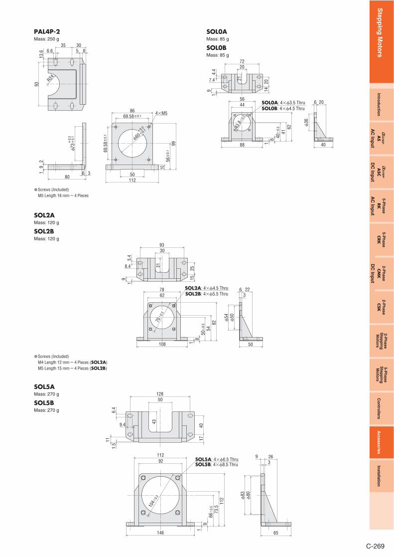
Dimensions (Unit = mm)
PAL0PMass: 35 g
31�0.34��3.5穴
23
8
23 153.5 5.5
453 2
42
60
6
50 31�
0.3
2448
29�
0.3
37.6 0�0.5
Screws (Included) M3 Length 10 mm ��� 4 Pieces
�
�
PAL2P-5Mass: 110 g
4 2
1
6
68
4.4
11
2025
R15
6.5
1.5
55
4�M4
7.5
40�
0.1 70
32
83
6250�0.1
50�
0.1
3.5
�36
�0.
1�
0.3
Screws (Included) M4 Length 12 mm ��� 4 Pieces
�
PAL2P-2Mass: 110 g
4�M4
7.5
40±
0.1 70
3283
47.14±0.162
�38
.1+
0.1
+0.
3
4 2168 R15
6.5
1.5
55
47.14±
0.1
114.4
253.5
206
Screws (Included) M4 Length 12 mm ��� 4 Pieces
�
Screws (Included) M5 Length 16 mm ��� 4 Pieces
�
PAL4P-5Mass: 250 g
9
4�M5
R24
13.66.6
35 30
1 6
2
8050
112
10 56�
0.1
99
70�0.1
86
70�
0.1
3
93
5 8
60�0.1�0.3
ORIENTAL MOTOR GENERAL CATALOGUE
Step
pin
g M
oto
rs
C-268
PAL4P-2Mass: 250 g
R246.6
35 309
1 36
2
80 50112
1056±
0.1
99
86
�60+0.1+0.3
69.5
8±0.
1
69.58±0.1
13.6
93
5 8
�73+
0.1
+0.
3
4�M5
Screws (Included) M5 Length 16 mm ��� 4 Pieces
�
SOL0AMass: 85 g
SOL0BMass: 85 g
206
�36
4088
56
94.
4
7.4
1
44
18
4162
40�
0.5
SOL0A: 4��3.5 ThruSOL0B: 4��4.5 Thru
7220
2014
2143
.8�
0.3
SOL2AMass: 120 g
SOL2BMass: 120 g
2263
�54
�50
50108
5.4
2515
8.4
91
18
5482
50�
0.5
SOL2A: 4��4.5 ThruSOL2B: 4��5.5 Thru
9330
7862
3170
�0.
3
Screws (Included) M4 Length 12 mm ��� 4 Pieces (SOL2A)M5 Length 15 mm ��� 4 Pieces (SOL2B)
SOL5AMass: 270 g
SOL5BMass: 270 g
2693
�83
�80
65146
92
116.
4
9.4
1.5
112
19
73.5
112
66�
0.5
SOL5A: 4��6.5 ThruSOL5B: 4��8.5 Thru
12850
4017
104�
0.3
43
�
Step
pin
g M
oto
rsIn
tro d
uctio
nA
SA
SC5-P
hase
RK
5-Ph
aseCR
KA
C In
pu
tA
C In
pu
tD
C In
pu
t
2-Ph
aseCM
K2-P
hase
CSK
2-Ph
aseS
tepp
ing
Mo
tors
5-Ph
aseS
tepp
ing
Mo
tors
Co
ntro
llersA
ccessories
Installatio
n
DC
Inp
ut
C-269

DIN Rail Mounting Plate This installation plate is convenient for installing the driver of AS Series on DIN rails with ease.
Product LineModel Applicable Product
PADP01 AS Series driver
Dimensions (Unit = mm)
PADP01Mass: 20 g
Screws (Included) M3 Length 8 mm ��� 3 Pieces
34
16.8
145.
5
11
89
49
8
4.518
120
DIN Rail Center
�
�
�
DIN Rail Mounting Plate
ORIENTAL MOTOR GENERAL CATALOGUE
Step
pin
g M
oto
rs
C-270