a/c manifold gauge set
TRANSCRIPT

LIMITED WARRANTYPERFORMANCE TOOL® extends only the following warranties, and only to original retail purchasers. These warranties give specific legal rights. Except where prohibited by local law, the law of the State of Washington governs all warranties and all exclusions and limitations of warranties and remedies. There may be other rights which vary from state to state.PERFORMANCE TOOL® warrants the product to be free from defects in materials and workmanship under normal use and service. A defective prod-uct may be returned for a free replacement within 90 days from the date of purchase, provided that product is returned to place of purchase immedi-ately after discovery of defect. After 90 days and up to one year from date of purchase, PERFORMANCE TOOL® will replace at no charge any parts which our examination shall disclose to be defective and under warranty. These warranties shall be valid only when a sales receipt showing the date of purchase accompanies the defective product or defective part (s) being returned. For part (s) after 90 days, please remit your request, postage prepaid to: PERFORMANCE TOOL, P.O. Box 88259 Tukwila, WA 98138These warranties exclude blades, bits, punches, dies, bulbs, fuses, hoses, and other consumables which must be replaced under normal use and service. These warranties shall not apply to any product or part which is used for a purpose for which it is not designed, or which has been repaired or altered in any way so as to affect adversely its performance or reliability, nor shall these warranties apply to any product or part which has been subject to misuse, neglect, accident or wear and tear incident to normal use and service. PERFORMANCE TOOL® does not authorize any other person to make any warranty or to assume any liability in connection with its products.Except for warranties of title and the limited express warranties set forth above, PERFORMANCE TOOL® makes no express or implied warranties of any kind with respect to its products. In particular, PERFORMANCE TOOL® makes no implied warranty of merchantability and no implied warranty of fitness for any particular purpose, except that for goods purchased primarily for personal, family or household use and not for commercial or business use, PERFORMANCE TOOL® makes an implied warranty of merchantability (and, if otherwise applicable, an implied warranty of fitness for a particu-lar purpose), but only for the particular qualities or characteristics, and for the duration, expressly warranted above.The laws on limitation of implied warranties may differ from state to state, so the above limitations may not apply in all cases.PERFORMANCE TOOL® shall not be liable for consequential, incidental or special damages resulting from or in any manner related to any product, or to the design, use, or any inability to use the product. The sole and exclusive remedy for a defective product or part shall be the repair, or replacement thereof as provided above. The laws on limitation of remedies or on consequential, incidental or special damages may vary from state to state, so the above limitations may not apply in all cases. © Copyright 2012 WILMAR CORPORATION, P.O. Box 88259 Tukwila, WA 98138
A/C Manifold Gauge Set
OWNER'S MANUALStock Number W89730
IMPORTANT SAFETY INSTRUCTIONS, READ AND UNDERSTAND ALL INSTRUCTIONSFailure to follow all instructions detailed in this manual may result in serious personal injury. SAVE THESE INSTRUCTIONS
WARNINGTO PREVENT EXPLOSION, SERIOUS IN-
JURY, AND DEATH:
• Service of air conditioning systems must be done only by trained and experienced techni-cian to avoid overfilling. • Technicians opening refrigeration circuit in automotive air conditioning systems MUST be certified in refrigerant recovery and recycling procedures in compliance with section 609 of Clean Air Act Amendments of 1990.For additional information regarding ozone depletion and air conditioning service regula-tions, visit EPA’s website: www.epa.gov/ozone
WARNING: USE ONLY R-134A REFRIGERANT WITH THE A/C MANIFOLD GAUGE SET

PRODUCT SPECIFICATIONS
Blue (Low) Gauge 0-120psiBlue Hose ¼ in. FFL x 50 in.Red (High) Gauge 0-500psiRed Hose ¼ in. FFL x 50 in.Yellow Hose ½ in. ACME x 50 in.Gauge Accuracy +/-2%
1. Keep work area clean and well lit. 2. Keep children away. Children must never be allowed in the work area. Do not let them handle the A/C Mani-fold Gauge Set. 3. There are certain applications for which this A/C Manifold Gauge Set was designed. It will do the job bet-ter and more safely at the rate for which it was intended. Do not modify this A/C Manifold Gauge Set and do not use this A/C Manifold Gauge Set for a purpose for which it was not intended. 4. Dress properly. Do not wear loose clothing or jewelry as they can be caught in moving engine parts. Protec-tive clothes and nonskid footwear are recommended when working. Wear restrictive hair covering to contain long hair. 5. Wear ANSI-approved impact safety goggles and heavy-duty work gloves at all times during setup and use. 6. Do not overreach. Keep proper footing and balance at all times. 7. Maintain gauge with care. Keep the A/C Manifold Gauge Set clean for better and safer performance. Inspect hoses periodically, and if damaged, have them repaired by a qualified technician.8. Stay alert. Watch what you are doing, use common sense. Do not operate gauge when you are tired. 9. Check for damaged parts. Before using any gauge, any part that appears damaged should be carefully checked to determine that it will operate properly and perform its intended function. Check for alignment and binding of moving parts; any broken parts or mounting fixtures; and any other condition that may affect proper operation. Any part that is damaged should be properly repaired or replaced by a qualified technician. 10. Replacement parts and accessories. When servic-ing, use only identical replacement parts. Use of any other parts will void the warranty. Only use accessories intended for use with this gauge. 11. Do not operate gauge if under the influence of alco-hol or drugs. Read warning labels if taking prescription medicine to determine if your judgment or reflexes are impaired while taking drugs. If there is any doubt, do not operate the gauge. 12. Maintenance. For your safety, service and maintenance should be performed regularly by a qualified technician.
13. Industrial applications must follow OSHA requirements.14. People with pacemakers should consult their physician(s) before using this product. Electromagnetic fields in close proximity to a heart pacemaker could cause interference to or failure of the pacemaker. In addition, people with pacemakers should observe the following: Caution is necessary when near the coil, spark plug cables, or distributor of a running engine.16. The warnings, cautions, and instructions discussed in this instruction manual cannot cover all possible condi-tions and situations that may occur. It must be under-stood by the operator that common sense and caution are factors, which cannot be built into this product, but must be supplied by the operator.17. ONLY USE REFRIGERANT R-134a WITH THIS A/C MANIFOLD GAUGE SET.18. Do not start an engine in an enclosed area (like a garage). A running gasoline engine generates carbon monoxide; carbon monoxide is a colorless, odorless gas that can cause serious injury and death, if inhaled.19. Keep hands away from the moving parts and hot parts of vehicle’s engine.20. Read and understand all instructions and safety precautions as outlined in the vehicle manufacturer’s manual for air condition servicing. Only qualified me-chanics that are trained in servicing air conditioning systems should use this product.21. When warming up an engine in preparation for checking of the A/C system, make sure the vehicle’s transmission is placed in “Park” and the emergency brake is applied.22. Refrigerant can cause severe frostbite if it comes in contact with skin.Follow the safety warnings and instruc-tions provided by the refrigerant manufacturer.23. Do not disconnect any pressurized hose. Pressur-ized refrigerant can cause severe injury.24. Use caution when opening an air conditioning sys-tem line or can of refrigerant. When checking, always place a towel around the service valves of the air condi-tioning unit and Red and Blue Couplers (22 and 23).25. Keep refrigerant away from excessive heat as pressure in the container could increase enough to rupture the can.26. Do not discharge refrigerant into the atmosphere. Capture refrigerant into an approved recovery container (not included), and then dispose of properly. Contact your local Hazardous Waste Authority for disposal guidelines. 27. Only use refrigerant in a manner consistent with the air conditioning system’s repair manual.
SAVE THESEINSTRUCTIONS

APPLICATIONS
1. The Red HP Gauge (3) is used to measure high pressure compressor discharge side pressure.
2. The Blue LP Gauge (5) is used to measure low-pressure side suction or pressure.
3. The Manifold Valves (11) control the flow of refrigerant to and from the Yellow Hose (18), also called the Charge Hose.
4. The Coupler Valves (22,23) control the flow to the Gauges (3, 5) from the Red and Blue Hoses (17,19).
5. The Sight Glass (13) allows checking the appearance of the refrigerant.
6. The Yellow Hose (18), also called Charge Hose can be used three ways: a. Refrigerant recovery/evacuation. b. Charging (filling) the system. c. For checking, attach the Yellow Hose (18) to both branches of the T-fitting (16) to reduce the risk of leaks.7. The charge valve allows for simultaneous connection of a refrigerant recovery system.
8. General instructions for A/C service are outlined in this manual. Specific procedures for each individual system type and model should be referenced in the vehicle manufacturer’s specific A/C system service manual.
9. See Operation instructions that follow.
COMPONENTS AND FUNCTIONS
LOW-PRESSURE HIGH-PRESSURE (LP) BLUE SIDE (HP) RED SIDE
Charge Valve
Blue Coupler Storage Plug (6)
Blue Coupler (23)
Red Coupler (22)
Red Coupler Storage Plug (7)
Red HP Gauge (3)
Blue LP Gauge (5)
Red HP Manifold Valve
Blue LP Manifold Valve
Yellow Charge Hose Connector (16)
Red HP Hose Connector
Blue LP Hose Connector
Sight Glass (13)
OPERATION
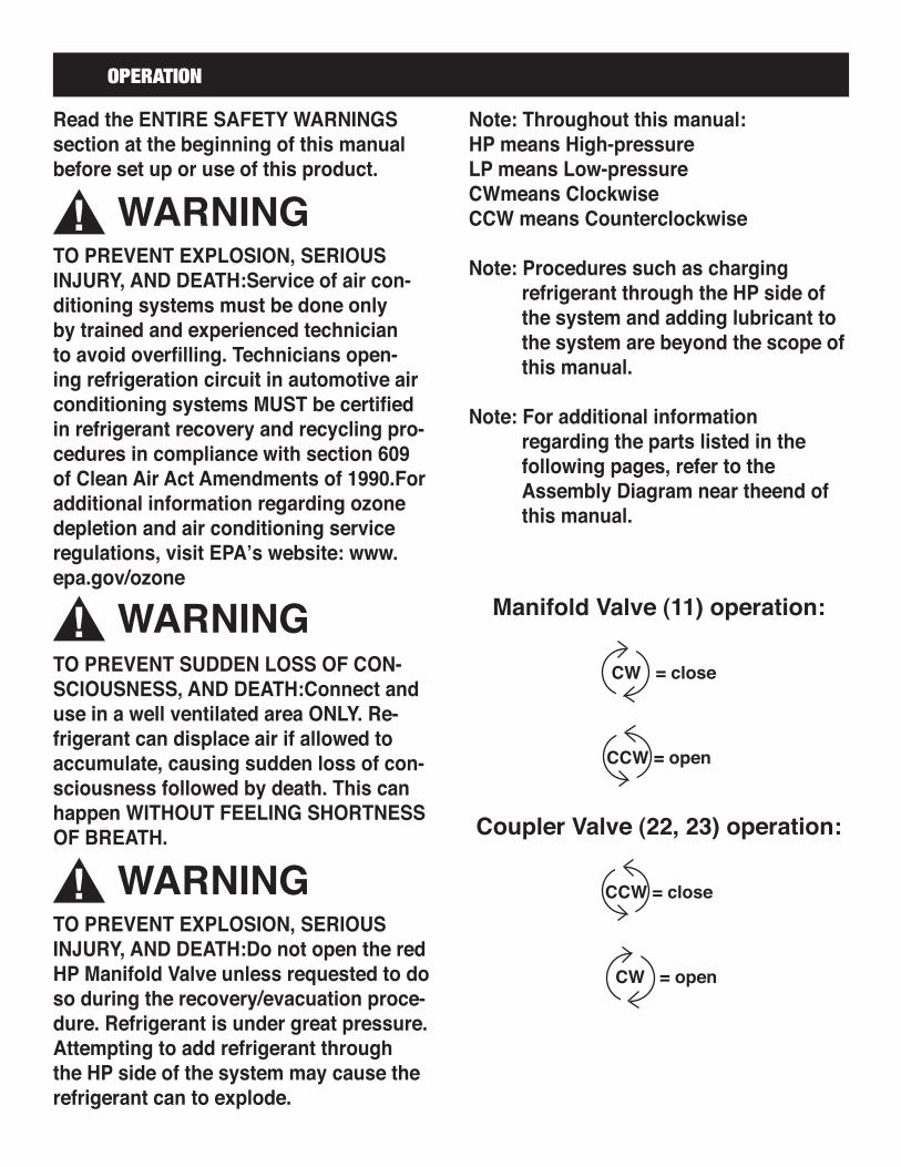
Read the ENTIRE SAFETY WARNINGS section at the beginning of this manual before set up or use of this product.
TO PREVENT EXPLOSION, SERIOUS INJURY, AND DEATH:Service of air con-ditioning systems must be done only by trained and experienced technician to avoid overfilling. Technicians open-ing refrigeration circuit in automotive air conditioning systems MUST be certified in refrigerant recovery and recycling pro-cedures in compliance with section 609 of Clean Air Act Amendments of 1990.For additional information regarding ozone depletion and air conditioning service regulations, visit EPA’s website: www.epa.gov/ozone
TO PREVENT SUDDEN LOSS OF CON-SCIOUSNESS, AND DEATH:Connect and use in a well ventilated area ONLY. Re-frigerant can displace air if allowed to accumulate, causing sudden loss of con-sciousness followed by death. This can happen WITHOUT FEELING SHORTNESS OF BREATH.
TO PREVENT EXPLOSION, SERIOUS INJURY, AND DEATH:Do not open the red HP Manifold Valve unless requested to do so during the recovery/evacuation proce-dure. Refrigerant is under great pressure.Attempting to add refrigerant through the HP side of the system may cause the refrigerant can to explode.
WARNING
WARNING
WARNING
Note: Throughout this manual:HP means High-pressureLP means Low-pressureCWmeans ClockwiseCCW means Counterclockwise
Note: Procedures such as charging refrigerant through the HP side of the system and adding lubricant to the system are beyond the scope of this manual.
Note: For additional information regarding the parts listed in the following pages, refer to the Assembly Diagram near theend of this manual.
Manifold Valve (11) operation:
CW = close
CCW = open
Coupler Valve (22, 23) operation:
CCW = close
CW = open

WARNINGTo prevent SERIOUS INJURY and DEATH:1. Wear ANSI-approved safety goggles and heavy-duty work gloves during setup and use.2. DO NOT OPEN either Manifold Valve (11) un-less directed to do so; otherwise, refrigerant leaks, A/C system contamination, and hazardous expulsion of pressurized refrigerant may occur.
3. Use in well-ventilated area only.4. Keep gauge and hoses away from moving engine parts.5. Turn off vehicle’s engine and A/C system before attaching gauge.6. The following procedure is to be per-formed only by a technician certified in re-frigerant recovery and recycling procedures, as explained previously.
DIAGNOSTIC CHECK
1. Close both Manifold Valves (11) by turning CW. Close both Coupler Valves (22, 23) by turning CCW.
2. CONNECT HOSES: a. Connect one end of the Blue Hose (19) to the Blue LP Hose Connector and the other end to the Blue Coupler (23). b. Connect one end of the Red Hose (17) to the Red LP Hose Connector and the other end to the Red Coupler (22). c. Connect one end of the Yellow Hose (18) to the Yellow Charge Hose Connec tor (16) and the other end to the Charge Valve on that Connector.
3. ATTACH COUPLERS: a. Attach the Blue Coupler (22) to the suction LP port on the A/C system. b. Attach the Red Coupler (23) to the discharge HP port on the A/C system.
4. PERFORM CHECK: a. To do a dynamic check: Turn on the vehicle and allow it to reach normal operating temperature. Then, turn on the A/C system. b. Open both Coupler Valves (22, 23) by turning CW. c. Read the pressure on both of the Gauges (3, 5) and compare to the manufacturer’s recommended readings.
5. AFTER: a. Close both Coupler Valves (22, 23) by turning CCW. b. Turn off the vehicle and the A/C system if dynamic check was done. c. Carefully disconnect the Couplers (22, 23), the hoses may contain residual refrig-erant. Pull back the knurled ring on each Coupler (22, 23) and store it on its Coupler Storage Plug (6, 7).
CW
KEEP CLOSED
KEEP CLOSED
CW
CWCW
REDBLUE
YELLOWTo charge
valve
To discharge HP port
To suction LP port

WARNINGTo prevent SERIOUS INJURY and DEATH:1. Wear ANSI-approved safety goggles and heavy-duty work gloves during setup and use.2. DO NOT OPEN either Manifold Valve (11) un-less directed to do so; otherwise, refrigerant leaks, A/C system contamination, and hazardous expulsion of pressurized refrigerant may occur.
3. Use in well-ventilated area only.4. Keep gauge and hoses away from moving engine parts.5. Turn off vehicle’s engine and A/C system before attaching gauge.6. The following procedure is to be performed only by a technician certified in refrigerant recovery and recycling procedures, as explained previously.
RECOVERY / EVACUATION
1. Close both Manifold Valves (11) by turning CW. Close both Coupler Valves (22, 23) by turning CCW.2. CONNECT HOSES: a. Connect one end of the Blue Hose (19) to the Blue LP Hose Connector and the other end to the Blue Coupler (23). b. Connect one end of the Red Hose (17) to the Red LP Hose Connector and the other end to the Red Coupler (22). c. Connect one end of the Yellow Hose (18) to the Yellow Charge Hose Connector (16) and the other end to the refrigerant recovery system / vacuum pump.3. ATTACH COUPLERS: a. Attach the Blue Coupler (22) to the suction LP port on the A/C system. b. Attach the Red Coupler (23) to the discharge HP port on the A/C system.4. PERFORM RECOVERY / EVACUATION: a. Turn on the refrigerant recovery system / vacuum pump. b. Open both Coupler Valves (22, 23) by turning CW and both Manifold Valves (11), turning them CCW. c. Read the amount of vacuum on the Blue LP Gauge (5).
5. AFTER: a. Shut off the refrigerant recovery system / vacuum pump when the vacuum level reaches the manufacturer’s recommended level. b. Close both Coupler Valves (22, 23) by turning CCW. c. Disconnect the Couplers (22, 23) from the A/C system. Pull back the knurled ring on each Coupler (22, 23) and store it on its Coupler Storage Plug (7 & 6, respectively).TURN VALVES AS SHOWN ONLY AFTER MAKING ALL CONNECTIONS AND TURNING ON REFRIG-ERANT RECOVERY SYSTEM / VACUUM PUMP
CCW
CWCW
REDBLUE
YELLOWTo refrigerant recovery system / vacuum pump
To discharge HP port
To suction LP port
CCW

WARNINGTo prevent SERIOUS INJURY and DEATH:1. Wear ANSI-approved safety goggles and heavy-duty work gloves during setup and use.2. DO NOT OPEN either Manifold Valve (11) un-less directed to do so; otherwise, refrigerant leaks, A/C system contamination, and hazardous expulsion of pressurized refrigerant may occur.
3. Use in well-ventilated area only.4. Keep gauge and hoses away from moving engine parts.5. Turn off vehicle’s engine and A/C system be-fore attaching gauge.6. The following procedure is to be performed only by a technician certified in refrigerant re-covery and recycling procedures, as explained previously.
CHARGING
1. Close both Manifold Valves (11) by turning CW. Close both Coupler Valves (22, 23) by turn-ing CCW.2. CONNECT HOSES: a. Connect one end of the Blue Hose (19) to the Blue LP Hose Connector and the other end to the Blue Coupler (23). b. Connect one end of the Red Hose (17) to the Red LP Hose Connector and the other end to the Red Coupler (22). c. Connect one end of the Yellow Hose (18) to the Yellow Charge Hose Connector (16) and the other end to refrigerant supply. KEEP THE CAN/CYLINDER UPRIGHT.3. ATTACH COUPLERS: a. Attach the Blue Coupler (23) to the suction LP port on the A/C system.
b. Attach the Red Coupler (23) to the dis charge HP port on the A/C system.4. PERFORM CHARGING: a. Turn on the vehicle and allow it to come up to normal operating temperature. Then, turn on the A/C system. b. Open the Blue Coupler Valve (23) only by turning CW and Blue Manifold Valve (11), turning it CCW.
5. AFTER: a. After charging manufacturer recommended amount of R-134a, close both Coupler Valves (22, 23) by turning CCW. b. Turn off the vehicle and the A/C system. c. Carefully disconnect the Couplers (22, 23) from the A/C system, the hoses may contain residual refrigerant. Pull back the knurled ring on each Coupler (22, 23) and store it on its Coupler Storage Plug (7 & 6, respectively).TURN VALVES AS SHOWN ONLY AFTER MAKING
ALL CONNECTIONS
CCW
CWCW
REDBLUE
YELLOWTo R-134a refrigerant
supply
To discharge HP port
To suction LP port
KEEP CLOSED
CW

WARNINGTO PREVENT SERIOUS INJURY FROM TOOL FAIL-URE: Do not use damaged equipment. If abnormal noise, vibration, or leaking air occurs, have the prob-lem corrected before further use.
1. Before each use, inspect the general condition of the A/C Manifold Set. Check for cracked or broken parts, damaged Hoses (17,18,19), and
any other condition that may affect safe operation. If a problem with the Set occurs, have it corrected before further use. Do not use damaged equipment.
2. Periodically, clean with a damp cloth using a mild detergent or solvent.3. When storing, keep the set clean and dry. Also, connect the Red Coupler (22) and the Blue Coupler (23) to its corresponding Coupler Storage Plug (7 or 6 respectively) to prevent contamination.
INSPECTION, MAINTENANCE AND CLEANING
Part Description Qty.
1 Rubber Cover 12 Manifold Body 13 Red HP Gauge 14 Hook 15 Blue LP Gauge 16 Blue Coupler Storage Plug 17 Red Coupler Storage Plug 18 Valve Seat 29 Valve Stem 210 Valve Nut 211 Manifold Valve 212 O-Ring 1
Part Description Qty.
13 Sight Glass 114 Ring Nut 115 Connector 216 T Connector 117 Red Hose (HP Refrigerant) 118 Yellow Hose (HP Refrigerant) 119 Blue Hose (LP Refrigerant) 120 Connector 221 O-Ring 222 Red Coupler (HP) 123 Blue Coupler (LP) 1
PARTS LIST AND ASSEMBLY DIAGRAM HP means High-Pressure LP means Low-Pressure
PLEASE READ THE FOLLOWING CAREFULLYTHE MANUFACTURER AND/OR DISTRIBUTOR HAS PROVIDED THE PARTS LIST AND ASSEMBLY DIAGRAM IN THIS MANUAL AS A REFERENCE TOOL ONLY. NEITHER THE MANUFACTURER OR DISTRIBUTOR MAKES ANY REPRESENTATION OR WARRANTY OF ANY KIND TO THE BUYER THAT HE OR SHE IS QUALIFIED TO REPLACE ANY PARTS OF THE PRODUCT. IN FACT, THE MANUFACTURER AND/OR DISTRIBUTOR EXPRESSLY STATES THAT ALL REPAIRS AND PARTS REPLACEMENTS SHOULD BE UNDERTAKEN BY CERTIFIED AND LICENSED TECHNICIANS, AND NOT BY THE BUYER. THE BUYER ASSUMES ALL RISKS AND LIABILITY ARISING OUT OF HIS OR HER REPAIRS TO THE ORIGINAL PRODUCT OR REPLACEMENT PARTS THERETO, OR ARISING OUT OF HIS OR HER INSTALLATION OF REPLACEMENT PARTS THERETO.